

Page 1
JVE
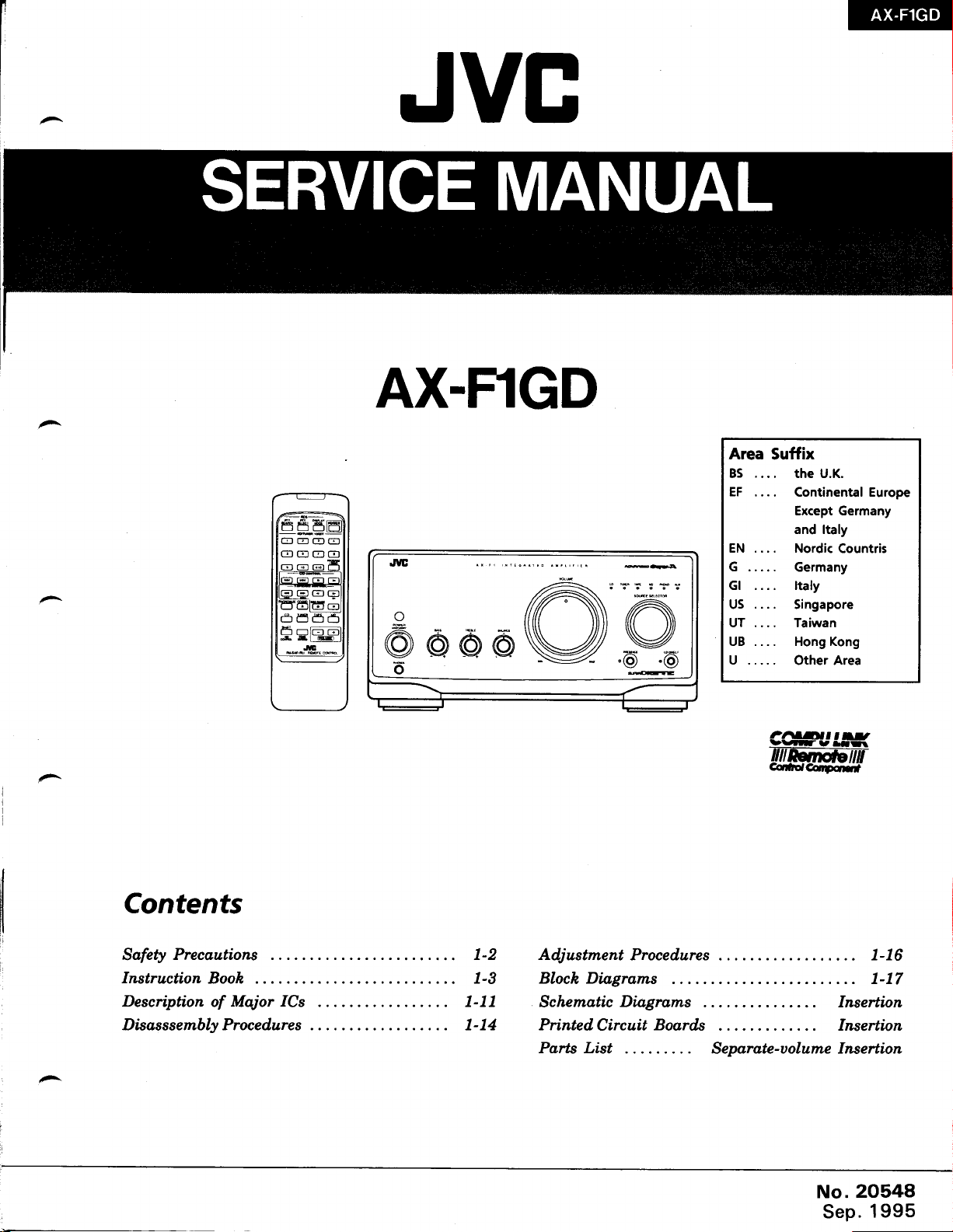
AX.FlGD
Area
Suffix
...
BS
. the U.K.
EF
.... Continental Europe
Except Germany
and ltaly
EN.... NordicCountris
G .....
Gl ltaly
US
UT .... Taiwan
UB .... Hong Kong
U . ... .
....
Germany
Singapore
Other Area
Contents
Sofety
Instruction
Description
Disas
Precoutions
Booh
of Major
s sembly
Proce dure s
ICs
1-2
1-3
1-11
1-14
Adjustment
Bloch Diagroms
Schematic
Printed.
Parts List
Procedures ... . 1-16
Di.ogroms
Circuit
Boords
Seporate-uolume
No.2O548
Sep.1995
1-17
Insertion
Inseftion
Insertion
Page 2
AX-FIGD
Safety Precautions
1.
The design
specially
original design
be identical
qualified persorlnel
2. Alterations
alterations
of this
for safety
purposes.
unless authorized in writing
to those used in
only.
of the
of
design or circuitry
product
the
void the manufacturer's
perconal
for
3. Many
injury
electrical
or
and mechanical
characteristics. These
protection
the
rated
for higher voltage,
characteristics
having
such
List in the
same
safety characteristics
Service
4.
The leads in
the like
Manual may
to
edges for the
afforded by them necessarily
are identified
features
Service Manual. The
products
the
be separated from
prevention
original lead routing
have
been returned to
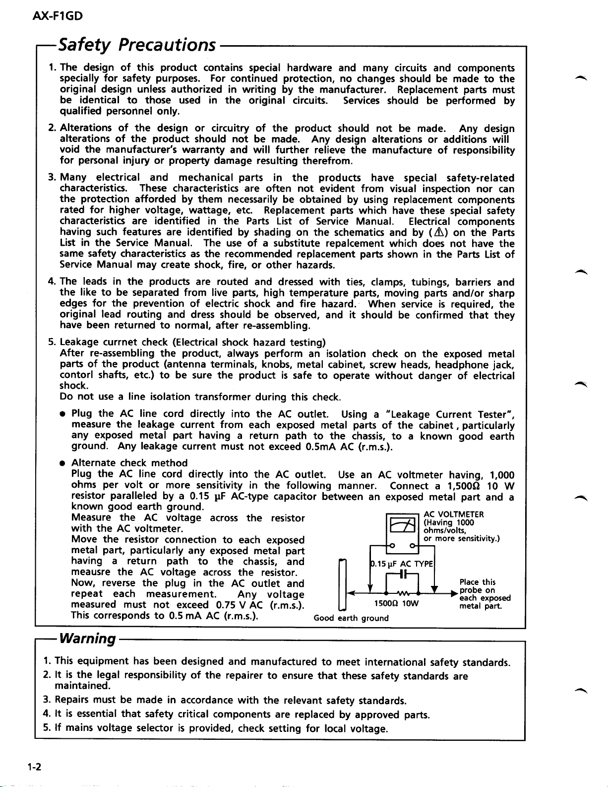
5. Leakage
After
parts
contorl
currnet
check
re-assembling
product
the
of
shafts, etc.) to be
shock.
Do
not use a line
o Plug
the AC line
measure
any
exposed metal
ground.
o Alternate
Plug
the AC
ohms
resistor
known
per
paralleled
good
Measure
with
the AC
Move the
metal
having
part,
a return
meausre
Now,
repeat
reverse
each measurement.
measured
This
corresponds
the leakage
Any leakage
the
the AC voltage
isolation
check method
line cord
volt
or more
earth
AC voltage
voltmeter.
resistor
particularly
the
must
not
to
product
contains special hardware and many
For
continued
protection,
by
the original
the
of
should
warranty
property
characteristics
not
be made. Any
and will further
damage resulting therefrom.
parts
in the
are often not
be
wattage,
Replacement
etc.
in the Parts List
are identified
by shading on the schematics
use
of a substitute repalcement
as the recommended
create shock, fire,
are routed
live
of electric shock
and
dress should
or other hazards.
and dressed with ties,
parts,
high
and
be observed, and it
normal, after re-assembling.
(Electrical
product,
the
(antenna
sure the
cord
directly into the
current from
part
current must
directly into
by
a 0.15
shock hazard testing)
always
terminals,
perform
knobs, metal
product
transformer
during this
each
having
a return
not
the AC
sensitivity in
pF
AC-type
the following
is
AC outlet.
exposed metal
path
exceed 0.5mA AC
capacitor
ground.
across the resistor
connection
any
path
to
each exposed
exposed metal
to
the
chassis, and
part
across the resistor.
plug
in the
AC
outlet and
Any voltage
exceed
0.75 V AC
0.5 mA AC
(r.m.s.).
(r.m.s.).
circuits and components
no
changes should be made to the
the manufacturer.
Replacement
circuits. Services should be
product
should not be made.
design alterations
or additions will
relieve the manufacture
products
evident
have
from
special safety-related
visual inspection nor
obtained by using replacement
parts
which have these
of Service Manual.
Electrical
and by
(A)
which does not have the
replacement
parts
shown in the Parts
clamps, tubings,
temperature
fire
hazard. When
isolation
an
parts,
moving
should be
check
parts
service is required,
confirmed that they
on the exposed metal
cabinet, screw heads,
safe to
operate without
danger of electrical
check.
Using a
parts
to
the chassis, to
"Leakage
of the cabinet,
a known
(r.m.s.).
outlet. Use an
manner.
between
Good
earth
AC voltmeter having,
Connect a 1,500Q
an exposed metal
AC VOLTMETER
(Having
ohms/volts,
or
lspF
AC TY
1s000
10w
ground
parts
must
performed
by
Any design
of responsibility
can
components
special safety
components
on the Parts
List of
barrierc and
and/or sharp
the
headphone
jack,
Current Tester",
particularly
good
earth
I,OOO
10 W
part
and a
1000
more
sensitivity.)
Place this
probe
on
each exposed
part.
metal
Warning
1.
This
equipment has
2. lt is
3. Repairs must
4. lt is
5. lf mains
1-2
the legal
maintained.
essential that
responsibility
be made
voltage
selector is
been
designed and
of the repairer
in accordance
safety
critical
provided,
manufactured
to
ensure that
with
the relevant
to meet
safety
components are replaced
check setting
for local voltage.
international
these
safety standards
standards.
by approved
parts.
safety
are
standards.
Page 3
N(-FlGD
lCs
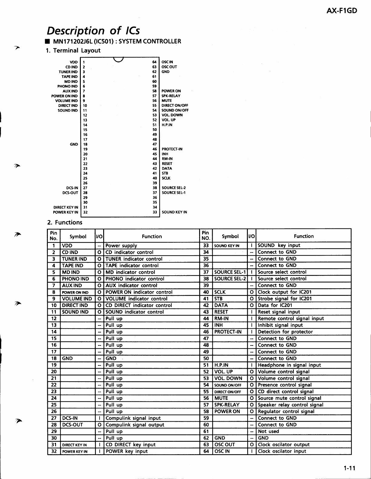
Description
MN171ZO2JGL(lCs01)
7
T
I
1. Terminal Layout
VDD
1
CD IND
IND
IND
DCSIN
KEYIN
2
3
4
5
5
7
8
9
10
11
l2
13
t4
l5
16
17
18
r9
20
21
22
23
24
25
26
27
28
29
30
IN
31
32
TUNER IND
TAPE IND
MDIND
PHONO IND
AUXIND
POWER ON
VOTUME IND
DIRECTIND
SOUND
DCS.OUT
DIRECT KEY
POWER
of
: SYSTEM CONTROLLER
osc tN
u
oscour
63
62
GNO
6l
60
s9
POWERON
58
s7
SPK.RELAY
MUTE
56
DIRECTON/OFF
55
54
s3
52
51
50
49
48
47
46
45
4
43
42
41
/O
39
38
37
36
35
34
33
ON/OFF
SOUND
VOL. DOWN
VOL UP
H.P.IN
PROTECT-IN
INH
RM.IN
RESET
DATA
SIB
SCLK
SOURCE 5EL-2
SOURCE SEL-1
SOUND KEY
IN
2. Functions
v
Pin
No.
1 VDD
Symbol r/o
Power
2 CD IND o CD
TUNER IND
3
4 TAPE IND o TAPE
o TUNER
Function
supply
indicator
control
indicatorcontrol 3s
indicator
control
5 MD IND o MD indicator control 37
6 PHONO IND o
7
AUX IND o AUX indicator control
PHONO indicator
control
8 PC'WER OI{ IND o POWER ON indicator control
up
indicator
control
v
10 DIRECT IND
11 SOUND IND
CD DIRECT indicator control 42 DATA o Data
o
SOUND indicator control 43 RESET I Reset siqnal
o
12 Pull
9 VOLUME IND o VOLUME
13
14
Pull up
Pull up 46 PROTECT-IN I Detection for
15 Pull up 47 Connect to GND
16
17 Pull
18
GND GND 50 Connect to GND
Pull up 48 Connect to GND
up 49 Connect
19 Pull up
20 Pull
21
22 Pull
23
up 52 VOL. UP o Volume control siqnal
Pull up s3 VOL. DOWN
up 54 SOUND ON/OFF
Pull up 55 DIRECTON/OFF o CD direct control siqnal
24 Pull up s6 MUTE
25 Pull
26 Pull
up 57
up 58
27 DCS-|N I Compulink signal input 59 Connect
28 DCS-OUT o Compulink siqnal output
29 Pull
30
31 DIRECT KEY
IN I
up
Pull
up 62
CD DIRECT
key input 63
32 POWER KEY IN I POWER key input u osc rN I Clock oscilator
Pin
NO.
33
34
Symbol t/o
SOUND KEY
IN SOUND key input
Connect
Function
to GND
Connect to GND
36
SOURCE SEL-I
38 SOURCE SEL-z
Connect
I Source
I Source
39 Connect
40 SCLK o Clock output
41 STB o Strobe siqnal
to
select
select
to GND
GND
control
control
for 1C201
for 1C201
for 1C201
input
M RM.IN I Remote control siqnal
45
INH
I Inhibit
siqnal
input
protector
to GND
H.P.IN I Headphone in
51
SPK.RELAY
POWER
Volume
o
Presence control siqnal
o
Source mute
o
o Speaker
ON o Requlator control siqnal
siqnal
control siqnal
control siqnal
relav
control siqnal
to GND
60 Connect to GND
61 Not used
GND GND
osc our o
Clock oscilator output
input
input
input
Page 4

A)(-FlGD
t GPlU501X(1C502)
181639-CV(1C351) : Motor
I
1.
Terminal Layout
tNl
GND
Vcont
tN2
: Receiver for remote
OUT
Vcc
NC
OUT2
controller
Limiter
Driver
f
2. Block Diagram
tNl
1
-l
f
Functions
3.
1-12
tNl
H
L
H H
L
rN2
L
H
L
OUT 1
H
L
OFF
OFF
OUT 2
L cLocKwtsE
H COUNTER.CLOCKWISE
OFF WAITING
OFF
MOTOR
WAITING
s
-J
cc
Page 5

N(-FlGD
I VCs022-2(tC7s1)
1. Terminal
Layout
: SUPER
Block Diagram
2.
v
r----
123456789
Thermal
Compensation
7
Super-A
!
Thermal
Compensation
VC4580DD
F
^
NJM4558
A
OUT
A
A +IN
-vcc
(lCl
(1C352,363)
_IN
01,231,361,301)
:
Dual
: Dual
OP amp.
+Vcc
B
OUT
-IN
B
B
+IN
OP amp.
v
1-13
Page 6

AX.FIGD
Disass embly
Proced
u
res
(1)
Removing
t. Remove
of top
the rear side.
2. Remove
(2)
Removing
1. Remove the top cover.
2. Disconnect the connector
Pull out the
3.
4.
Remove
5. Disconnect the connectors
6. Remove 3
the top cover
2 screws
cover, and
the top cover.
the Front
Master volume
the nut
fastening the Master
screws @ and 3
@
4 screws
fastening
Panel Assembly
both sides
fastening
@
PA360.
knob, Tleble
(PA790,P202,P203,BC500)
hook
O
f
@xz
knob, Bass knob and
volume,
fastening bottom of the
Bass
and
Balance.
Balance
front
panel
knob.
assembly.
@x4
,(s
(3)
Removing the
1. Remove the top cover.
2. Remove the front
Pull
3.
4.
out the source selector
nut fastening
the
Remove 8 screws
remove it.
to
Control
(ENH-272-3)
PCB
panel
the source selector.
@
assembly.
fastening
knob
and
the control
remove
PCB
Mastervolume
%
Bass, Treble
Balance konb
$
konb
&
@
1-14
sDsG3008N
@
GBSG3008CC
@
SDSF2508Z
Page 7
A)(.F1GD
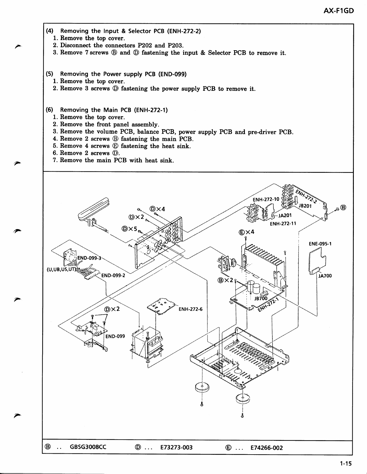
(4)
Removing
1.
Remove
2.
v
v
Disconnect
3. Remove
(5)
Removing
1.
Remove the
2.
Remove
(5)
Removing
1
Remove
2
Remove
3
Remove
4
Remove
5
Remove
6
Remove 2
7
Remove
the Input
the top cover.
the
7 screws
the Power
top eover.
3 screws
the Main
the top cover.
front
the
the volume
2 screws
4
screws @ fastening
screws
the main PCB
& Selector PCB
connectors P2O2
and @ fastening
@
supply PCB
fastening
@
PCB
panel
@
@.
assembly.
PCB,
fastening
with heat
(ENH-272-1)
balance PCB,
(ENH-272-2)
and P203.
the input
(END-099)
power
the
the main
heat
the
sink.
&
supply PCB
power
PCB.
sink.
supply PCB
Selector PCB
remove
to
and
to remove it.
it
pre-driver
ENH-272-10
PCB
@x+
(DX
2
F
END-099-2
@xs*
---___,,/
@x2
@x4
\
ENE-095-1
\
--).
lA>
IBTOO z
7
@x2
ENH-272-6
'w
T-1
END-099
;'"*:-78
i
@
&
E74266-oo2
1-1
5
7
@
GBsc3ooscc
@
E732n-ao3
Page 8

A)(-FlGD
ADJUSTMENT PROCEDURES
ldling
I
(1)
Current
Set the volume control to minimum during this adjustment.
(2)
T\En R?51 anil R?52 fully counterclockwise before the
(3)
Always
If the hegtsink is already warm fiom
(4)
Connect a DC voltmeter to R771 resietor's leads for left channel,
(5)
Adjust R751 for Ieft channel,
mV
start fmm cold, and allow 5 minutes to warm up before adjustment.
-
15mV.
or R752
previous
for right
use
channel, so that the
power
the conect adjustuent can not be made.
ie switch on.
F"772 for right channel.
or ta
DC
voltneter becomes
4.5
1-16
Page 9

AX-FIGD
Block Diagram
F
F
v
5v
l'rtF
r/!o
ulU.!
z
-i
{e
vq gq
e8
>.9
I rl
+(tl
O)t
5P
r.fr
F
<l
U@
aB
z6
ar.)
.o
>57
v2*
-
cr
utL
|
-;--t
3;Hi
<rsr
9
k!8$
ri-i
t I
=5EH
o
r3
-l
=]uF-
+F|'n
rf(r.l
3=ff
at1
-
o
xSEn
co-
E.
ur
=o
:1t\
o-
*E'i
gaa
a
sf
Or
I
Ctt
q
F
ul
u
z
ul
rrJ
pag$
E
A
tct
;=fn
1l
(
tlt
lO
uJ
rE
U
-
<*
aE
s
BSt
AG
F
lj.l
++
5e
F
C'T
(J)
lri ;
68
ro
sEi
REg
JO
-N
fRK
frqq
*;fi
;DD
,
frF
H>l
'5R
o
c
t
L!
3
o
o-
a
ug
Hff;
-rtLN
9eg
uF-
dno
3EA
r./r
H
&,o
2R=552.5252
Pvi
Fo-Holu
s=h
r--3
lu
Lr!!m
c.ts t
=fi
9>A
(n
lft
o
eEiF
dGt
1-17
Page 10

AX.FIGD
^
^
JVE
VICTOR
AUDIO DIVISION,
(No.20548)
COMPANY
OF JAPAN, LIMITED
YAMATO PLANT,
1644, SHIMOTSURUMA,
YAMATO.
SHI , KANAGAWA. KEN , 242, JAPAN
Printed in
9509(S)
Japan
 Loading...