

Page 1

SERVICE MANUAL
COLOUR TELEVISION
AV-T2912
Supplement
/ZAR
AV-T2912
BASIC CHASSIS
GA
The following item for the AV-T2912
Therefore, this service man ual describe s only the items which differ from those of the AV-T2922
service manual.
For details other than those described in this manual, please refer to the AV-T2922
manual (No.51917 Mar. 2002) .
■ OUTLINE
Since the picture tube was c hanged, we have issued the SERVICE MANUAL for AV-T292/ZAR.
Since the picture tube was c hanged, we have issued the SERVICE MANUAL for AV-T2912/ZAR.
■ HOW TO IDENTIFY MODELS
Identify that the model name “AV-T2912Z” is printed on the margin of the rating label affi xed
to the rear cover.
model was changed partly from AV-T2922
/ZAR
(AR)
(AR)
service
model.
(AR)
1
COPYRIGHT © 2001 VICTOR COMPANY OF JAPAN, LTD.
Page 2
A
V-T292
2
PARTS LIST
CAUTION
! The parts identified by the ! sym bol are impor tant for t he s afety. Whene ver r eplaci ng these parts, be s ure t o use s pec if ied o nes to secur e
the safet y .
!
The parts not ind ic ated in this Parts L ist and tho se whi ch are filled wi th lines in the Parts No. columns will not be supplied.
! P. W. Board Ass'y will not be supplied, but those which are filled with the Parts No. in the Parts No. columns will be s upplied.
ABBREVIATIONS OF R ESISTOR S, CAPACITORS AND TOLERANCES
RESISTORS CAPACITORS
C R Carbon Resistor C CAP. Ceramic Capacitor
F R Fusible Resistor E CAP. Electrolyt ic Capacitor
P R Plate Res istor M CAP. Mylar Capacitor
V R Variable Resisto
HV R High Voltage Resistor MF CAP. Metalized Film Capacitor
MF R Metal Film Resistor MM CAP. Metalized Mylar Capacitor
MG R Metal Glazed Resistor MP CAP. Metalized Polystyrol Capacitor
MP R Metal Plate Resi sto r PP CAP. Po lyp ropylen e Ca pa citor
OM R M etal Oxide Film Resistor PS CAP. Polystyrol Capacitor
CMF R Coating Metal Film Resistor TF CAP. Thin Film Capacitor
UNF R Non-F lammabl e Resi stor MPP CAP. Metalize d P olypr op ylene Cap acitor
CH V R Chip Variable Resistor TAN. CAP. Tantalum Capacitor
CH MG R Chip Metal Glazed Resistor CH C CAP. Chip Ceramic Capacitor
COMP. R Composition Resist or BP E CAP . Bi-Pola r El ectrolytic C a pacit or
LP TC R
Linear P ositive T emperat ure C o efficient
Resistor
r
HV CAP. High Voltage Capacitor
CH AL E CAP. Chip Aluminum Electrolytic Capacitor
CH AL BP CA P.
CH TAN. E CAP.
Chip A luminum B i-Po lar Cap acitor
Chip T ant alum Elec tr olytic Capacitor
CH AL BP E CAP.
Chip T ant alum Bi-Polar Electrolyt ic C a pac itor
TOLERANCES
FGJ KMNRHZ P
±1% ±2% ±5% ±10% ±20% ±30%
+30%
-10%
No.51917
+50%
-10%
+80%
-20%
+100%
-0%
31
Page 3
A
V-T2922
CONTENTS
!
USING PW BOARD & REMOT E CONTROL UNIT
・・・・・・・ ・・・・・・・・・・・・・ ・・・・・・・・・・・・ ・・・・・・・ ・・・・・・・・・・・・・ ・・
! EXPLODED VIEW PARTS LIST・・・・・・・ ・・・・・・・・・・・・・ ・・・・・・・・・・・・・・・・・・・ ・・・・・・・・・・・・・ ・・・・・・・・・・・・ ・・・・・・・ ・・・ 32
!
EXPLODED VIEW
!
PRINTED WIRING BOARD PARTS LIST
"
MAIN PW BOARD ASS’Y (With CRT SOCKET PW BOARD)・・・・・・・ ・・・・・・・・・・・・・ ・・・・・・・・・・・・・・・・・・・ ・・・・・・・・・・・ 34
"
FRONT CONTRO L PW BOARD ASS’Y
!
REMOTE CONTROL UNIT PARTS LIST ・・・・・・・ ・・・・・・・・・・・・・ ・・・・・・・・・・・・ ・・・・・・・・・・・・・・・・・・・・ ・・・・・・・・・・・・ 39
!
PACKING
!
PACKI NG PARTS LIST
・・・・・・・ ・・・・・・・・・・・・・ ・・・・・・・・・・・・・・・・・・・ ・・・・・・・・・・・・・ ・・・・・・・・・・・・ ・・・・・・・ ・・・・・・・・・・・・・ ・・・・・・・・・・・・・
・・・・・・・ ・・・・・・・・・・・・・ ・・・・・・・・・・・・ ・・・・・・・ ・・・・・・・・・・・・・ ・・・・・・・・・・・・ ・・・・・・・ ・・・・・・・・・・・・・ ・・・・
・・・・・・・ ・・・・・・・・・・・・・ ・・・・・・・・・・・・ ・・・・・・・ ・・・・・・・・・・・・・ ・・・・・・・・・・・・・・
・・・・・・・ ・・・・・・・・・・・・・ ・・・・・・・・・・・・・・・・・・・ ・・・・・・・・・・・・・ ・・・・・・・・・・・・ ・・・・・・・ ・・・・・・・・・・・・
USING P.W. BOARD & REMOTE CONTROL UNIT
Model
P.W.B AS S’Y
MAIN P.W.B
(W ith in CRT SOCKET PW B )
FRONT CO NTROL PWB SGA-4005A-R2
AV-T2922
SGA-1020A-R2
/AR
32
33
38
39
39
REMOTE CONTROL UNIT RM-C363-1H
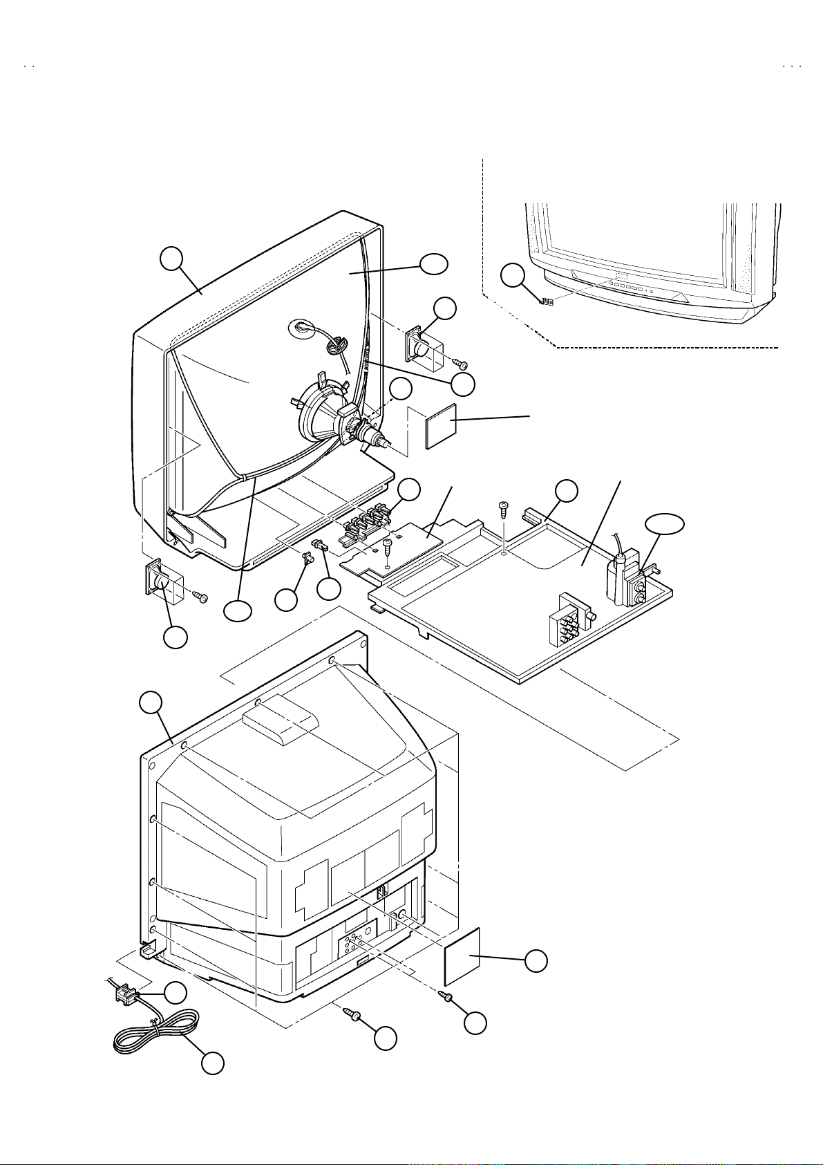
EXPLODED VIEW PARTS LIST
!
Ref.No. Part No. Part Name Description
V01 A68AJB82X02 PICTURE TUBE(C) Inc.DY,PC MAGNET, WEDGE
!
!
L01 CELD058-001J3 DEG.COIL
!
T1522 QQH0115-001 H.V.TRANSF. (Within MAIN PWB)
1 LC10571-002A-D FRONT CABINET
!
2 CHGB0015-0B BRAIDED WIRE
3 CHGB0016-0C BRAIDED WIRE(SUB)
6 CEBSS12D-04KJ2 SPEAKER (×2)SP01,SP02
7 LC20217-004B-A CONTROL KNOB
!
8 LC30856-002A-A POWER KNOB
!
!
9 CM12985-003-VA CHASSIS BASE
!
10 QMPR150-200-JC POWER CORD
!
11 CM23169-001-A POWER CORD CLAMP
12 LC10572-001B-D REAR COVER
!
13 QYSBSFG4016Z TAPPING SCREW (×11)
14 QYSBSB3010Z TAPPING SCREW (×2)
!
15 LC30462-008A-D RATING LABEL
16 LC30191-002A-A REMOCON LENS
!
17 CM48006-007-C JVC MARK
32
No.51917
Page 4
A
2
EXPLODED VIEW
(
)
V-T292
!
1
!
V01
3
FRONT
!
C ONT RO L PW B
7
17
6
2
CRT SOCKET PWB
W ith in MAIN PWB
!
MAIN PWB
9
!
T1522
!
!
!
L01
6
16
8
!
12
!
15
!
11
14
(×2)
10
!
(×11)
13
No.51917
33
Page 5

A
V-T2922
PRINTED WIRING BOARD PARTS LIST
MAIN PW BOARD ASS’Y (SGA-1020A-R2)
!
Symbol No. Part No. Part Name Description
RESISTOR
R1001 NRSA02J-563X MG R 56kΩ 1/10W J
R1003-04 NRSA02J-561X MG R 560Ω 1/10W J
R1006 NRSA02J-820X MG R 82Ω 1/10W J
R1101 NRSA02J-562X MG R 5.6kΩ 1/10W J
R1102 NRSA02J-182X MG R 1.8kΩ 1/10W J
R1103 QRE121J-101Y C R 100Ω 1/2W J
R1104 NRSA02J-180X MG R 18Ω 1/10W J
R1105 NRSA02J-270X MG R 27Ω 1/10W J
R1111 NRSA02J-394X MG R 390kΩ 1/10W J
R1112 NRSA02J-334X MG R 330kΩ 1/10W J
R1113 NRSA02J-101X MG R 100Ω 1/10W J
R1116 NRSA02J-680X MG R 68Ω 1/10W J
R1131 NRSA02J-102X MG R 1kΩ 1/10W J
R1132 NRSA02J-331X MG R 330Ω 1/10W J
R1133 NRSA02J-102X MG R 1kΩ 1/10W J
R1134 NRSA02J-271X MG R 270Ω 1/10W J
R1135 NRSA02J-471X MG R 470Ω 1/10W J
R1161 NRSA02J-332X MG R 3.3kΩ 1/10W J
R1162 NRSA02J-0R0X MG R 0.0Ω 1/10W J
R1163 NRSA02J-103X MG R 10kΩ 1/10W J
R1164 NRSA02J-102X MG R 1kΩ 1/10W J
R1165 NRSA02J-273X MG R 27kΩ 1/10W J
R1166 NRSA02J-103X MG R 10kΩ 1/10W J
R1167 NRSA02J-102X MG R 1kΩ 1/10W J
R1168 NRSA02J-101X MG R 100Ω 1/10W J
R1169 NRSA02J-561X MG R 560Ω 1/10W J
R1170 NRSA02J-683X MG R 68kΩ 1/10W J
R1201 NRSA02J-821X MG R 820Ω 1/10W J
R1202 NRSA02J-102X MG R 1kΩ 1/10W J
R1203 NRSA02J-821X MG R 820Ω 1/10W J
R1204 NRSA02J-681X MG R 680Ω 1/10W J
R1205 NRSA02J-152X MG R 1.5kΩ 1/10W J
R1213 NRSA02J-391X MG R 390Ω 1/10W J
R1215 NRSA02J-824X MG R 820kΩ 1/10W J
R1216 NRSA02J-0R0X MG R 0.0Ω 1/10W J
R1217 NRSA02J-563X MG R 56kΩ 1/10W J
R1220 NRSA02J-471X MG R 470Ω 1/10W J
R1251-52 NRSA02J-750X MG R 75Ω 1/10W J
R1301 NRSA02J-102X MG R 1kΩ 1/10W J
R1303-04 NRSA02J-562X MG R 5.6kΩ 1/10W J
R1307 NRSA02J-472X MG R 4.7kΩ 1/10W J
R1308 NRSA02J-682X MG R 6.8kΩ 1/10W J
R1309 NRSA02J-103X MG R 10kΩ 1/10W J
R1311 NRSA02J-273X MG R 27kΩ 1/10W J
R1312 NRSA02J-0R0X MG R 0.0Ω 1/10W J
R1314 NRSA02J-0R0X MG R 0.0Ω 1/10W J
R1341 NRSA02J-121X MG R 120Ω 1/10W J
R1342-43 NRSA02J-333X MG R 33kΩ 1/10W J
R1351-53 NRSA02J-151X MG R 150Ω 1/10W J
R1354-56 NRSA02J-331X MG R 330Ω 1/10W J
R1357-59 NRSA02J-101X MG R 100Ω 1/10W J
R1360-62 QRZ0111-152 C R 1.5kΩ 1/2W K
R1363-65 QRG029J-123 OM R 12kΩ 2W J
R1366-68 NRSA02J-272X MG R 2.7kΩ 1/10W J
R1401 NRSA02J-103X MG R 10kΩ 1/10W J
R1402 NRSA02J-682X MG R 6.8kΩ 1/10W J
R1403 NRSA02J-0R0X MG R 0.0Ω 1/10W J
R1404 NRSA02J-102X MG R 1kΩ 1/10W J
R1405 NRSA02J-221X MG R 220Ω 1/10W J
R1406-08 NRSA02J-472X MG R 4.7kΩ 1/10W J
R1410 NRSA02J-0R0X MG R 0.0Ω 1/10W J
R1412 QRE121J-3R9Y C R 3.9Ω 1/2W J
R1413 QRE121J-561Y C R 560Ω 1/2W J
R1414 QRX01GJ-R68 MF R 0.68Ω 1W J
R1415 QRE121J-102Y C R 1kΩ 1/2W J
R1416 NRSA02J-563X MG R 56kΩ 1/10W J
R1418 NRSA02J-563X MG R 56kΩ 1/10W J
R1419 NRSA02J-183X MG R 18kΩ 1/10W J
!
Symbol No. Part No. Part Name Description
RESISTOR
R1421 NRSA02J-0R0X MG R 0.0Ω 1/10W J
R1422 NRSA02J-0R0X MG R 0.0Ω 1/10W J
R1423 NRSA02J-103X MG R 10kΩ 1/10W J
R1501 NRSA02J-0R0X MG R 0.0Ω 1/10W J
R1503 NRSA02J-103X MG R 10kΩ 1/10W J
R1504 NRSA02J-104X MG R 100kΩ 1/10W J
R1505 NRSA02J-822X MG R 8.2kΩ 1/10W J
R1506 NRSA02J-102X MG R 1kΩ 1/10W J
R1510 NRSA02J-0R0X MG R 0.0Ω 1/10W J
R1512 NRSA02J-103X MG R 10kΩ 1/10W J
R1513 NRSA02J-0R0X MG R 0.0Ω 1/10W J
R1514 NRSA02J-333X MG R 33kΩ 1/10W J
R1521 QRL039J-182 OM R 1.8kΩ 3W J
R1523 NRSA02J-222X MG R 2.2kΩ 1/10W J
R1524 QRE121J-103Y C R 10kΩ 1/2W J
R1525 QRG01GJ-561 OM R 560Ω 1W J
R1526 QRL029J-152 OM R 1.5kΩ 2W J
R1529 NRSA02J-621X MG R 620Ω 1/10W J
R1532 QRL039J-182 OM R 1.8kΩ 3W J
R1533 QRE121J-220Y C R 22Ω 1/2W J
R1544 QRL029J-223 OM R 22kΩ 2W J
R1562 QRA14CF-6341Y MF R 6.34kΩ 1/4W F
!
!
R1563 QRA14CF-3241Y MF R 3.24kΩ 1/4W F
R1581 QRE121J-273Y C R 27kΩ 1/2W J
R1582 QRE121J-393Y C R 39kΩ 1/2W J
R1584 QRE121J-223Y C R 22kΩ 1/2W J
R1603 NRSA02J-682X MG R 6.8kΩ 1/10W J
R1605 NRSA02J-821X MG R 820Ω 1/10W J
R1607 NRSA02J-682X MG R 6.8kΩ 1/10W J
R1609 NRSA02J-821X MG R 820Ω 1/10W J
R1611 NRSA02J-223X MG R 22kΩ 1/10W J
R1613 NRSA02J-333X MG R 33kΩ 1/10W J
R1620 NRSA02J-183X MG R 18kΩ 1/10W J
R1621 QRT039J-2R2 MF R 2.2Ω 3W J
R1622 NRSA02J-183X MG R 18kΩ 1/10W J
R1626 NRSA02J-822X MG R 8.2kΩ 1/10W J
R1631 NRSA02J-473X MG R 47kΩ 1/10W J
R1651 NRSA02J-102X MG R 1kΩ 1/10W J
R1652 NRSA02J-561X MG R 560Ω 1/10W J
R1653 NRSA02J-272X MG R 2.7kΩ 1/10W J
R1654 NRSA02J-333X MG R 33kΩ 1/10W J
R1655 NRSA02J-332X MG R 3.3kΩ 1/10W J
R1656 NRVA02D-152X MF R 1.5kΩ 1/10W D
R1658 NRVA02D-153X MF R 15kΩ 1/10W D
R1660 NRSA02J-512X MG R 5.1kΩ 1/10W J
R1661 NRSA02J-473X MG R 47kΩ 1/10W J
R1662-65 NRSA02J-123X MG R 12kΩ 1/10W J
R1666-67 NRSA02J-562X MG R 5.6kΩ 1/10W J
R1668 NRSA02J-473X MG R 47kΩ 1/10W J
R1669-70 NRSA02J-471X MG R 470Ω 1/10W J
R1671 NRSA02J-102X MG R 1kΩ 1/10W J
R1672 NRSA02J-102X MG R 1kΩ 1/10W J
R1673-74 NRSA02J-823X MG R 82kΩ 1/10W J
R1675-76 NRSA02J-181X MG R 180Ω 1/10W J
R1677 NRSA02J-682X MG R 6.8kΩ 1/10W J
R1678 NRSA02J-223X MG R 22kΩ 1/10W J
R1679 NRSA02J-223X MG R 22kΩ 1/10W J
R1680 NRSA02J-223X MG R 22kΩ 1/10W J
R1681 NRSA02J-223X MG R 22kΩ 1/10W J
R1682 NRSA02J-683X MG R 68kΩ 1/10W J
R1685 NRSA02J-0R0X MG R 0.0Ω 1/10W J
R1686 NRSA02J-0R0X MG R 0.0Ω 1/10W J
R1687 NRSA02J-0R0X MG R 0.0Ω 1/10W J
R1688 NRSA02J-0R0X MG R 0.0Ω 1/10W J
R1691 NRSA02J-102X MG R 1kΩ 1/10W J
R1692 NRSA02J-102X MG R 1kΩ 1/10W J
R1701 NRSA02J-563X MG R 56kΩ 1/10W J
R1702 NRSA02J-223X MG R 22kΩ 1/10W J
34
No. 51917
Page 6

A
V-T292
2
Symbol No. Part No. Part Name Description
!
RESISTOR
R1703 NRSA02J-0R0X MG R 0.0Ω 1/10W J
R1704 NRSA02J-103X MG R 10kΩ 1/10W J
R1705 NRSA02J-102X MG R 1kΩ 1/10W J
R1706 NRSA02J-563X MG R 56kΩ 1/10W J
R1707 NRSA02J-103X MG R 10kΩ 1/10W J
R1708 NRSA02J-0R0X MG R 0.0Ω 1/10W J
R1709 NRSA02J-103X MG R 10kΩ 1/10W J
R1710 NRSA02J-102X MG R 1kΩ 1/10W J
R1711 NRSA02J-124X MG R 120kΩ 1/10W J
R1712 NRSA02J-184X MG R 180kΩ 1/10W J
R1713 NRSA02J-102X MG R 1kΩ 1/10W J
R1714 NRSA02J-103X MG R 10kΩ 1/10W J
R1715 NRSA02J-224X MG R 220kΩ 1/10W J
R1716 NRSA02J-102X MG R 1kΩ 1/10W J
R1717 NRSA02J-102X MG R 1kΩ 1/10W J
R1721 NRSA02J-102X MG R 1kΩ 1/10W J
R1722 NRSA02J-561X MG R 560Ω 1/10W J
R1724 NRSA02J-221X MG R 220Ω 1/10W J
R1725 NRSA02J-682X MG R 6.8kΩ 1/10W J
R1726 NRSA02J-221X MG R 220Ω 1/10W J
R1727 NRSA02J-682X MG R 6.8kΩ 1/10W J
R1728 NRSA02J-221X MG R 220Ω 1/10W J
R1729 NRSA02J-682X MG R 6.8kΩ 1/10W J
R1730 NRSA02J-221X MG R 220Ω 1/10W J
R1731 NRSA02J-682X MG R 6.8kΩ 1/10W J
R1732 NRSA02J-682X MG R 6.8kΩ 1/10W J
R1734 NRSA02J-102X MG R 1kΩ 1/10W J
R1735-36 NRSA02J-473X MG R 47kΩ 1/10W J
R1737 NRSA02J-683X MG R 68kΩ 1/10W J
R1738 NRSA02J-562X MG R 5.6kΩ 1/10W J
R1740 NRSA02J-101X MG R 100Ω 1/10W J
R1741 NRSA02J-103X MG R 10kΩ 1/10W J
R1742 NRSA02J-102X MG R 1kΩ 1/10W J
R1743 NRSA02J-392X MG R 3.9kΩ 1/10W J
R1744 NRSA02J-102X MG R 1kΩ 1/10W J
R1745 NRSA02J-392X MG R 3.9kΩ 1/10W J
R1746 NRSA02J-102X MG R 1kΩ 1/10W J
R1747 NRSA02J-392X MG R 3.9kΩ 1/10W J
R1748 NRSA02J-102X MG R 1kΩ 1/10W J
R1749 NRSA02J-102X MG R 1kΩ 1/10W J
R1754-55 NRSA02J-222X MG R 2.2kΩ 1/10W J
R1756 NRSA02J-103X MG R 10kΩ 1/10W J
R1761 NRSA02J-102X MG R 1kΩ 1/10W J
R1762 NRSA02J-153X MG R 15kΩ 1/10W J
R1764 NRSA02J-105X MG R 1MΩ 1/10W J
R1765 NRSA02J-122X MG R 1.2kΩ 1/10W J
R1766 NRSA02J-102X MG R 1kΩ 1/10W J
R1771-72 NRSA02J-221X MG R 220Ω 1/10W J
R1773 NRSA02J-0R0X MG R 0.0Ω 1/10W J
R1774 NRSA02J-102X MG R 1kΩ 1/10W J
R1775 NRSA02J-102X MG R 1kΩ 1/10W J
R1799 NRSA02J-333X MG R 33kΩ 1/10W J
R1801-03 NRSA02J-221X MG R 220Ω 1/10W J
R1811 NRSA02J-0R0X MG R 0.0Ω 1/10W J
R1812 NRSA02J-0R0X MG R 0.0Ω 1/10W J
R1813 NRSA02J-0R0X MG R 0.0Ω 1/10W J
R1815 NRSA02J-0R0X MG R 0.0Ω 1/10W J
R1901 QRF154K-4R7 UNF R 4.7Ω 15W K
!
R1902 QRL039J-393 OM R 39kΩ 3W J
!
R1905 QRF154J-680 UNF R 68 Ω 15W J
R1910 QRE121J-564Y C R 560kΩ 1/2W J
R1911 QRN141J-183Y C R 18kΩ 1/4W J
R1921 QRE121J-681Y C R 680Ω 1/2W J
R1922-23 QRT029J-R22 MF R 0.22Ω 2W J
R1924 QRE121J-103Y C R 10kΩ 1/2W J
R1925 QRE121J-102Y C R 1kΩ 1/2W J
R1926 QRE121J-152Y C R 1.5kΩ 1/2W J
R1929 QRE121J-332Y C R 3.3kΩ 1/2W J
R1932 QRE121J-4R7Y C R 4.7Ω 1/2W J
R1941 QRK129J-150 C R 15Ω 1/2W J
Symbol No. Part No. Part Name Description
!
RESISTOR
R1942 NRSA02J-223X MG R 22kΩ 1/10W J
R1943 QRE121J-152Y C R 1.5kΩ 1/2W J
R1944 NRSA02J-103X MG R 10kΩ 1/10W J
R1945 NRSA02J-332X MG R 3.3kΩ 1/10W J
R1946 NRSA02J-123X MG R 12kΩ 1/10W J
R1948 NRSA02J-152X MG R 1.5kΩ 1/10W J
R1949 NRSA02J-153X MG R 15kΩ 1/10W J
R1950 NRSA02J-103X MG R 10kΩ 1/10W J
R1951 NRSA02J-332X MG R 3.3kΩ 1/10W J
R1952 NRSA02J-472X MG R 4.7kΩ 1/10W J
R1959 NRSA02J-0R0X MG R 0.0Ω 1/10W J
R1961 QRT029J-1R2 MF R 1.2Ω 2W J
R1962 QRT029J-1R2 MF R 1.2Ω 2W J
R1964 QRE121J-272Y C R 2.7kΩ 1/2W J
R1965 QRE121J-473Y C R 47kΩ 1/2W J
R1966 QRE121J-223Y C R 22kΩ 1/2W J
R1981 QRZ0057-825 C R 8.2MΩ 1W J
!
CAPACITOR
C1001 QETN1HM-106Z E CAP. 10µF 50V M
C1007 QETN1CM-477Z E CAP. 470µF 16V M
C1008-09 QETN1EM-476Z E CAP. 47µF 25V M
C1011 NCB21HK-103X C CAP. 0.01µF 50V K
C1101-02 NCB21HK-103X C CAP. 0.01µF 50V K
C1104-05 NCB21HK-103X C CAP. 0.01µF 50V K
C1111 QETN1EM-476Z E CAP. 47µF 25V M
C1112-14 NCB21HK-103X C CAP. 0.01µF 50V K
C1116 QFV71HJ-224Z MF CAP. 0.22µF 50V J
C1117 QETN1EM-476Z E CAP. 47µF 25V M
C1118 NCB21HK-103X C CAP. 0.01µF 50V K
C1119 NDC21HJ-681X C CAP. 680pF 50V J
C1120 QETN1HM-474Z E CAP. 0.47µF 50V M
C1123-24 NCB21HK-103X C CAP. 0.01µF 50V K
C1161 QETN1HM-106Z E CAP. 10µF 50V M
C1163-64 NDC21HJ-470X C CAP. 47pF 50V J
C1165-66 NCB21HK-103X C CAP. 0.01µF 50V K
C1202 QETN1CM-107Z E CAP. 100µF 16V M
C1205 NDC21HJ-680X C CAP. 68pF 50V J
C1207 QFLC1HJ-104Z M CAP. 0.1µF 50V J
C1208 QETN1HM-475Z E CAP. 4.7µF 50V M
C1209 QETN1CM-227Z E CAP. 220µF 16V M
C1210 NCB21HK-103X C CAP. 0.01µF 50V K
C1211 NDC21HJ-681X C CAP. 680pF 50V J
C1212 QFLC1HJ-104Z M CAP. 0.1µF 50V J
C1213 QETN1HM-105Z E CAP. 1µF 50V M
C1214 QFLC1HJ-104Z M CAP. 0.1µF 50V J
C1215 QETN1HM-106Z E CAP. 10µF 50V M
C1251-52 QETN1HM-106Z E CAP. 10µF 50V M
C1255 QETN1HM-106Z E CAP. 10µF 50V M
C1256 QETN1CM-107Z E CAP. 100µF 16V M
C1291-92 QETN1CM-107Z E CAP. 100µF 16V M
C1294 QETN1CM-107Z E CAP. 100µF 16V M
C1296 QETN1CM-107Z E CAP. 100µF 16V M
C1301-02 NDC21HJ-150X C CAP. 15pF 50V J
C1303 NDC21HJ-120X C CAP. 12pF 50V J
C1304 NCB21HK-103X C CAP. 0.01µF 50V K
C1305 NDC21HJ-120X C CAP. 12pF 50V J
C1306 QETN1EM-476Z E CAP. 47µF 25V M
C1307 NCB21HK-103X C CAP. 0.01µF 50V K
C1308-09 QFLC1HJ-104Z M CAP. 0.1µF 50V J
C1311 QFV71HJ-334Z MF CAP. 0.33µF 50V J
C1312 QFLC1HJ-103Z M CAP. 0.01µF 50V J
C1313 QETN1HM-475Z E CAP. 4.7µF 50V M
C1342 QETN1HM-335Z E CAP. 3.3µF 50V M
C1354-55 NDC21HJ-271X C CAP. 270pF 50V J
C1356 NDC21HJ-331X C CAP. 330pF 50V J
C1357 QETN1CM-107Z E CAP. 100µF 16V M
C1382 QCZ0121-102 C CAP. 1000pF 3kV Z
!
C1401-02 QETN1HM-105Z E CAP. 1µF 50V M
No. 51917
35
Page 7

A
V-T2922
Symbol No. Part No. Part Name Description
!
CAPACITOR
C1403 QEM61EK-225Z E CAP. 2.2µF 25V K
C1405 QFLC1HJ-104Z M CAP. 0.1µF 50V J
C1406 QFLC1HJ-103Z M CAP. 0.01µF 50V J
C1410 QETN1VM-107Z E CAP. 100µF 35V M
C1411 QETN1VM-477Z E CAP. 470µF 35V M
C1412 QFLC2AK-393Z M CAP. 0.039µF 100V K
C1413 QETM1VM-228 E CAP. 2200µF 35V M
C1414 QETN1HM-105Z E CAP. 1µF 50V M
C1415 QFN31HJ-152Z M CAP. 1500pF 50V J
C1501 QETN1CM-107Z E CAP. 100µF 16V M
C1503 NCB21HK-103X C CAP. 0.01µF 50V K
C1505-06 NCB21HK-103X C CAP. 0.01µF 50V K
C1507 QETN1HM-105Z E CAP. 1µF 50V M
C1511 QETN1HM-106Z E CAP. 10µF 50V M
C1521 QCB32HK-151Z C CAP. 150pF 500V K
C1522 QCB32HK-331Z C CAP. 330pF 500V K
C1523 QETN2CM-105Z E CAP. 1µF 160V M
C1524 QFZ0198-133 MPP CAP. 0.013 µF1.5kVH±3%
!
C1525 QFZ0119-474 MPP CAP. 0.47µF 200V ±3%
!
!
C1526 QEZ0203-107 E CAP. 100µF 160V M
C1541 QETM2EM-336 E CAP. 33µF 250V M
C1542 QCB32HK-821Z C CAP. 820pF 500V K
C1543 QETM1VM-108 E CAP. 1000 µF 35V M
C1544 QCB32HK-821Z C CAP. 820pF 500V K
C1546 QETN1CM-227Z E CAP. 220µF 16V M
C1547 QETN1CM-108Z E CAP. 1000µF 16V M
C1548 QCZ0122-821 C CAP.
C1561 QETN1VM-107Z E CAP. 100µF 35V M
C1581 QFLC1HJ-473Z M CAP. 0.047µF 50V J
C1583 QFLC1HJ-104Z M CAP. 0.1µF 50V J
C1584 QFLC2AJ-104Z M CAP. 0.1µF 100V J
C1604 QENC1HM-474Z BP E CAP. 0.47 µF 50V M
C1607 QENC1HM-474Z BP E CAP. 0.47 µF 50V M
C1609 QETN1CM-107Z E CAP. 100µF 16V M
C1613 QETM1EM-108 E CAP. 1000 µF 25V M
C1615 QETM1EM-108 E CAP. 1000µF 25V M
C1617 QETM1EM-108 E CAP. 1000µF 25V M
C1618 QFV71HJ-224Z MF CAP. 0.22µF 50V J
C1622 QETN1HM-105Z E CAP. 1µF 50V M
C1623-24 QENC1HM-474Z BP E CAP. 0.47 µF 50V M
C1631 QETN1EM-476Z E CAP. 47µF 25V M
C1637-38 NCB21HK-392X C CAP. 3900pF 50V K
C1651 NCB21HK-103X C CAP. 0.01µF 50V K
C1652 QETN1CM-107Z E CAP. 100µF 16V M
C1653 QETN1EM-476Z E CAP. 47µF 25V M
C1654 QFLC1HJ-104Z M CAP. 0.1µF 50V J
C1655 QENC1HM-475Z BP E CAP. 4.7µF 50V M
C1656 QENC1HM-105Z E CAP. 1µF 50V M
C1657 QETN1HM-225Z E CAP. 2.2µF 50V M
C1658 NCB21HK-473X C CAP. 0.047 µF 50V K
C1659 QETN1HM-474Z E CAP. 0.47µF 50V M
C1660-61 QFLC1HJ-104Z M CAP. 0.1µF 50V J
C1662 QBTC1CK-335Z TAN.CAP. 3.3µF 16V K
C1663 QETN1HM-105Z E CAP. 1µF 50V M
C1664 QBTC1CK-106Z TAN.CAP. 10µF 16V K
C1665-66 QETN1HM-105Z E CAP. 1µF 50V M
C1667 QETN1HM-336Z E CAP. 33µF 50V M
C1668 QETN1HM-105Z E CAP. 1µF 50V M
C1669-70 QENC1HM-105Z E CAP. 1µF 50V M
C1671 QETN1HM-225Z E CAP. 2.2µF 50V M
C1672 NCB21HK-222X C CAP. 2200pF 50V K
C1673 QFLC1HJ-104Z M CAP. 0.1µF 50V J
C1674 QETN1HM-225Z E CAP. 2.2µF 50V M
C1675 NCB21HK-222X C CAP. 2200pF 50V K
C1676 QFLC1HJ-104Z M CAP. 0.1µF 50V J
C1677 NCB21HK-223X C CAP. 0.022µF 50V K
C1679 QETN1HM-105Z E CAP. 1µF 50V M
C1680 QETN1EM-476Z E CAP. 47µF 25V M
C1682-83 QETN1HM-475Z E CAP. 4.7µF 50V M
C1684-86 QETN1HM-106Z E CAP. 10µF 50V M
Symbol No. Part No. Part Name Description
!
CAPACITOR
C1691-92 QETN1HM-106Z E CAP. 10µF 50V M
C1693-94 NCB21HK-392X C CAP. 3900pF 50V K
C1701 NDC21HJ-102X C CAP. 1000pF 50V J
C1703 NCB21HK-102X C CAP. 1000pF 50V K
C1704 NCB21HK-103X C CAP. 0.01µF 50V K
C1705 NDC21HJ-471X C CAP. 470pF 50V J
C1706 QFLC1HJ-104Z M CAP. 0.1µF 50V J
C1707 NDC21HJ-180X C CAP. 18pF 50V J
C1708 NDC21HJ-220X C CAP. 22pF 50V J
C1709 QETN1EM-476Z E CAP. 47µF 25V M
C1710 QFLC1HJ-104Z M CAP. 0.1µF 50V J
C1711 NCB21HK-103X C CAP. 0.01µF 50V K
C1712-13 QETN1CM-107Z E CAP. 100µF 16V M
C1714 QFLC1HJ-104Z M CAP. 0.1µF 50V J
C1715 NDC21HJ-150X C CAP. 15pF 50V J
C1716 NDC21HJ-390X C CAP. 39pF 50V J
C1717 NDC21HJ-151X C CAP. 150pF 50V J
C1718 NRSA02J-0R0X MG R 0.0Ω 1/10W J
C1719 QETN1HM-106Z E CAP. 10µF 50V M
C1720 NDC21HJ-151X C CAP. 150pF 50V J
C1722 NCB21HK-103X C CAP. 0.01µF 50V K
C1761 QETN1HM-105Z E CAP. 1µF 50V M
C1762 NDC21HJ-221X C CAP. 220pF 50V J
C1763 NCB21HK-102X C CAP. 1000pF 50V K
C1765 NDC21HJ-101X C CAP. 100pF 50V J
C1766 QENC1HM-474Z BP E CAP. 0.47 µF 50V M
C1771 QETN1EM-476Z E CAP. 47µF 25V M
C1772 NCB21HK-103X C CAP. 0.01µF 50V K
C1773 QETN1HM-105Z E CAP. 1µF 50V M
C1779 NDC21HJ-100X C CAP. 10pF 50V J
C1780 NRSA02J-0R0X MG R 0.0Ω 1/10W J
C1781 NRSA02J-0R0X MG R 0.0Ω 1/10W J
C1805 QETN1CM-227Z E CAP. 220µF 16V M
C1806 NCB21HK-103X C CAP. 0.01µF 50V K
C1811-13 NCB21HK-103X C CAP. 0.01µF 50V K
C1901 QFZ9072-104 MF CAP. 0.1µFAC275V K
!
C1902 QFZ9072-104 MF CAP. 0.1µFAC275V K
!
C1903 QCZ9074-472 C CAP. 4700pFAC250V M
!
C1904 QCZ9074-472 C CAP. 4700pFAC250V M
!
!
C1905 QCZ9074-472 C CAP. 4700pFAC250V M
!
C1906 QEZ0371-337 E CAP. 330μF 400V M
C1921 QCZ0325-222 C CAP. 2200pF 2kV K
C1924 QETN1VM-477Z E CAP. 470µF 35V M
C1925 QFN31HJ-102Z M CAP. 1000pF 50V J
C1926 QFN31HJ-222Z M CAP. 2200pF 50V J
C1928 QFLC1HJ-104Z M CAP. 0.1µF 50V J
C1931 QCZ0122-391 C CAP . 390pF 2kV K
C1941 QCZ0325-561 C CAP. 560pF 2kV K
!
C1942 QEZ0203-107 E CAP. 100µF 160V M
C1943 QCB32HK-561Z C CAP. 560pF 500V K
C1944 QETN1CM-477Z E CAP. 470µF 16V M
C1945 QETN1CM-108Z E CAP. 1000µF 16V M
C1946 QETN1EM-107Z E CAP. 100µF 25V M
C1947 QETN1HM-106Z E CAP. 10µF 50V M
C1952 QETN1EM-108Z E CAP. 1000µF 25V M
C1953 QCZ0122-561 C CAP. 560pF 2kV K
C1957 QCB31HK-471Z C CAP. 470pF 50V K
C1961 QETN1CM-107Z E CAP. 100µF 16V M
C1962 QETN1HM-476Z E CAP. 47µF 50V M
!
C1981 QCZ9075-471 C CAP. 470pFAC250V K
!
C1982 QCZ9075-222 C CAP. 2200pFAC250V M
C1983 QCZ9075-471 C CAP. 470pFAC250V K
!
TRANSFORMER
T1111 CELT001-209J3 C.WAVE TRANSF.
T1521 CE42034-002 H.DRIVE TRANSF.
!
T1522 QQH0115-001 H.V.TRANSF.
T1921 CETS090-001J8 SWITCH.TRANSF.
!
36
No. 51917
Page 8

A
V-T292
2
Symbol No. Part No. Part Name Description
!
COIL
L1001 QQL244J-150Z PEAKING COIL
L1003 QQL244J-4R7Z PEAKING COIL
L1101 QQLZ014-R22 PEAKING COIL
L1131 QQL244J-220Z PEAKING COIL
L1161 QQL244J-220Z PEAKING COIL
L1205 QQL244J-4R7Z PEAKING COIL
L1301 QQL244J-390Z PEAKING COIL
L1381 QQL244J-390Z PEAKING COIL
L1501 QQL244J-4R7Z PEAKING COIL
!
L1521 QQR1137-002 LINEARITY COIL
L1701-02 QQL244J-4R7Z PEAKING COIL
L1704 QQL39BK-8R2Z COIL 8.2µH K
L1771 QQL244J-4R7Z PEAKING COIL
L1941-42 QQL26AK-820Z COIL 82µH K
DIODE
D1001 MTZJ33A-T2 ZENER DIODE
D1201 1SS133-T2 SI.DIODE
D1202 MTZJ7.5B-T2 ZENER DIODE
D1253-56 MTZJ9.1C-T2 ZENER DIODE
D1341 1SS133-T2 SI.DIODE
D1401 1N4003-T2 SI.DIODE
D1402 MTZJ75-T2 ZENER DIODE
D1510 1SS133-T2 SI.DIODE
D1512 RH3G-F1 SI.DIODE
D1541 RH1S-T3 SI.DIODE
!
D1542 RU3AM-LFC4 SI.DIODE
!
D1543 RGP10J-5025-T3 SI.DIODE
D1544 RH1S-T3 SI.DIODE
D1561 1SS81-T2 SI.DIODE
!
D1562 MTZJ7.5S-T2 ZENER DIODE
!
D1581 RGP10J-5025-T3 SI.DIODE
D1582 MTZJ9.1B-T2 ZENER DIODE
D1631 1SS133-T2 SI.DIODE
D1632 1SS133-T2 SI.DIODE
D1633 1SS133-T2 SI.DIODE
D1634 1SS133-T2 SI.DIODE
D1656-57 MTZJ9.1C-T2 ZENER DIODE
D1691-92 MTZJ9.1C-T2 ZENER DIODE
D1701 1SS133-T2 SI.DIODE
D1703 1SS133-T2 SI.DIODE
D1704 1SS133-T2 SI.DIODE
D1710 MTZJ5.6A-T2 ZENER DIODE
D1712 1SS133-T2 SI.DIODE
D1713 1SS133-T2 SI.DIODE
D1771-72 MTZJ5.6A-T2 ZENER DIODE
D1801-03 MTZJ15B-T2 ZENER DIODE
D1805 MTZJ15B-T2 ZENER DIODE
!
D1901 GSIB460 DIODE
!
D1903 RGP10J-5025-T3 SI.DIODE
D1905 MTZJ6.8A-T2 ZENER DIODE
D1921 RGP10J-5025-T3 SI.DIODE
!
D1922 RGP10J-5025-T3 SI.DIODE
!
D1923 MTZJ15A-T2 ZENER DIODE
D1924 1SS133-T2 SI.DIODE
D1927 1SS133-T2 SI.DIODE
D1928 1SS133-T2 SI.DIODE
D1929 MTZJ15A-T2 ZENER DIODE
D1941 RU3AM-LFC4 SI.DIODE
!
D1942 RGP10J-5025-T3 SI.DIODE
D1943 1SS133-T2 SI.DIODE
D1945 MTZJ5.1B-T2 ZENER DIODE
D1948 RU3YX-LFC4 SI.DIODE
D1961 MTZJ7.5A-T2 ZENER DIODE
D1962 1SS133-T2 SI.DIODE
TRANSISTOR
Q1101 2SC5083/L-P/-T SI.TRANSISTOR
Q1131 2SC2412K/QR/-X SI.TRANSISTOR
Q1161 2SC2412K/QR/-X SI.TRANSISTOR
Q1201-02 2SC2412K/QR/-X SI.TRANSISTOR
Q1301-02 2SC2412K/QR/-X SI.TRANSISTOR
Q1341-42 2SC2412K/QR/-X SI.TRANSISTOR
Q1351-53 2SC4544-LB SI.TRANSISTOR
Symbol No. Part No. Part Name Description
!
TRANSISTOR
Q1401 2SC2412K/QR/-X SI.TRANSISTOR
!
Q1511 2SC2785/JH/-T SI.TRANSISTOR
Q1521 BSN304-T F.E.T.
Q1522 2SD2499-LB SI.TRANSISTOR H.OUT
!
Q1601 2SC2412K/QR/-X SI.TRANSISTOR
Q1603 DTC124EKA-X DIGI.TRANSISTOR
Q1604-05 DTC323TK-X DIGI.TRANSISTOR
Q1631 2SA1037AK/QR/-X SI.TRANSISTOR
Q1651-54 DTC323TK-X DIGI.TRANSISTOR
Q1701-02 2SC2412K/QR/-X SI.TRANSISTOR
Q1703 DTC124EKA-X DIGI.TRANSISTOR
Q1761 2SC2412K/QR/-X SI.TRANSISTOR
Q1921 2SA933AS/QR/-T SI.TRANSISTOR
Q1941 2SA966/OY/-T SI.TRANSISTOR
Q1942-44 2SC2412K/QR/-X SI.TRANSISTOR
Q1961 2SA949/Y/Z1-T SI.TRANSISTOR
IC
IC1001 AN7805F I.C(MONO-ANA)
IC1101 M52342SP I.C(MONO-ANA)
IC1201 TB1230N I.C(D IGI-OTHER)
IC1251 BA7612N I.C(MONO-ANA)
IC1291 AN78N05 I.C.(M)
IC1292 AN78L09-T I.C(MONO-ANA)
IC1293 AN78L05-T I.C(MONO-ANA)
IC1401 LA7840 I.C(MONO-ANA)
IC1541 AN7809F I.C(MONO-ANA)
!
IC1601 LA4485 I.C(MONO-ANA)
IC1651 UPC1851BCU I.C(MONO-ANA)
IC1652 BA15218N I.C(MONO-ANA)
IC1701 M37267M8-100SP I C
IC1702 AT24C02-T2922AR I.C. (SERVICE)
IC1703 L78LR05E-MA I.C(MONO-ANA)
!
IC1921 STR-F6654 I.C(HYBRID)
IC1941 SE130N I.C(H)
!
OTHERS
CF1001 QAX0349-001 CERAMIC FILTER
CF1131 QAX0339-001 CERAMIC FILTER
CF1161 SFSH4.5MCB CERAMIC FILTER
CL1002 QZW0028-002 WIRE CLAMP
!
CP1941 ICP-N75-Y I.C.PROTECT
CP1942 ICP-N50-Y I.C.PROTECT
!
EF1301 CE42142-222Z EMI FILTER
!
F1901 QMF51E2-3R15J4 FUSE 3.15A
FC1901 CEMG002-001Z FUSE CLIP
FC1902 CEMG002-001Z FUSE CLIP
!
FR1542 QRZ9024-R56 F R 0.56 Ω 2W K
!
FR1543 QRZ9023-2R2 F R 2.2 Ω 2W J
FR1561 QRZ9017-4R7 F R 4.7 Ω 1/4W J
!
!
FR1585 QRZ9021-2R2 F R 2.2 Ω 1W J
FR1586 QRE121J-682Y C R 6.8kΩ 1/2W J
J1001 QNN0086-001 PIN JACK
K1401 QQR0621-001Z BEADS CORE
K1921 QQR0582-001Z BEADS CORE
K1923 QQR0582-001Z BEADS CORE
K1941-43 QQR0582-001Z BEADS CORE
LF1901 QQR0676-001 LINE FILTER
!
!
PC1921 TLP621/GR/ I.C(PH.COUPLER)
SF1101 QAX0324-002 SAW FILTER
SK1351 CE42535-001J1 C.R.T.SOCKET
!
TH1901 QAD0101-9R0 P.THERMISTOR
!
!
TH1902 QAD0101-9R0 P.THERMISTOR
!
TU1001 QAU0229-001 TUNER
!
VA1901 ERZV10V621CS VARISTOR
X1301 QAX0305-001Z CRYSTAL
X1701 QAX0468-001Z CRYSTAL
No. 51917
37
Page 9

A
V-T2922
FRONT CONTROL PW BOARD AS S’Y
(SG A-4 005A-R2)
!
Symbol No. Part No. Part Name Description
RESISTOR
R4701 QRE121J-103Y C R 10kΩ 1/2W J
R4702 QRE121J-562Y C R 5.6kΩ 1/2W J
R4703-04 QRE121J-103Y C R 10kΩ 1/2W J
R4705 QRE121J-562Y C R 5.6kΩ 1/2W J
R4706 QRE121J-103Y C R 10kΩ 1/2W J
R4707-08 QRE121J-223Y C R 22kΩ 1/2W J
R4709 QRE121J-561Y C R 560Ω 1/2W J
R4710-11 QRE121J-223Y C R 22kΩ 1/2W J
R4712 QRE121J-561Y C R 560Ω 1/2W J
R4713 QRE121J-103Y C R 10kΩ 1/2W J
CAPACITOR
C4701 QETN1EM-476Z E CAP. 47µF 25V M
C4702 QCB32HK-561Z C CAP. 560pF 500V K
COIL
L4701 QQL03BJ-560Z COIL 56µH J
DIODE
D4702 SPR-39MVWF L.E.D.
TRANSISTOR
Q4701 2SA933S(QR)-T SI.TRANSISTOR
Q4702 2SC1740S/QR/-T SI.TRANSISTOR
IC
IC4701 PIC-37243SR IR DETECT UNIT
OTHERS
S4701 QSW0619-003Z PUSH SWITCH VOL+
S4702 QSW0619-003Z PUSH SWITCH VOL-
S4703 QSW0619-003Z PUSH SWITCH CH+
S4704 QSW0619-003Z PUSH SWITCH CHS4705 QSW0619-003Z PUSH SWITCH MENU
S4901 QSP4K21-C01 PUSH SWITCH POWER
!
LC30190-001B-A L.E.D.HOLDER
38
No. 51917
Page 10
A
2
REMOTE CONTROL UNIT PARTS LIST (RM-C363-1H)
Ref.No. Part No. Part Name Description
!
25-1168 B BATTARY COVER (RM-C363-1H)
V-T292
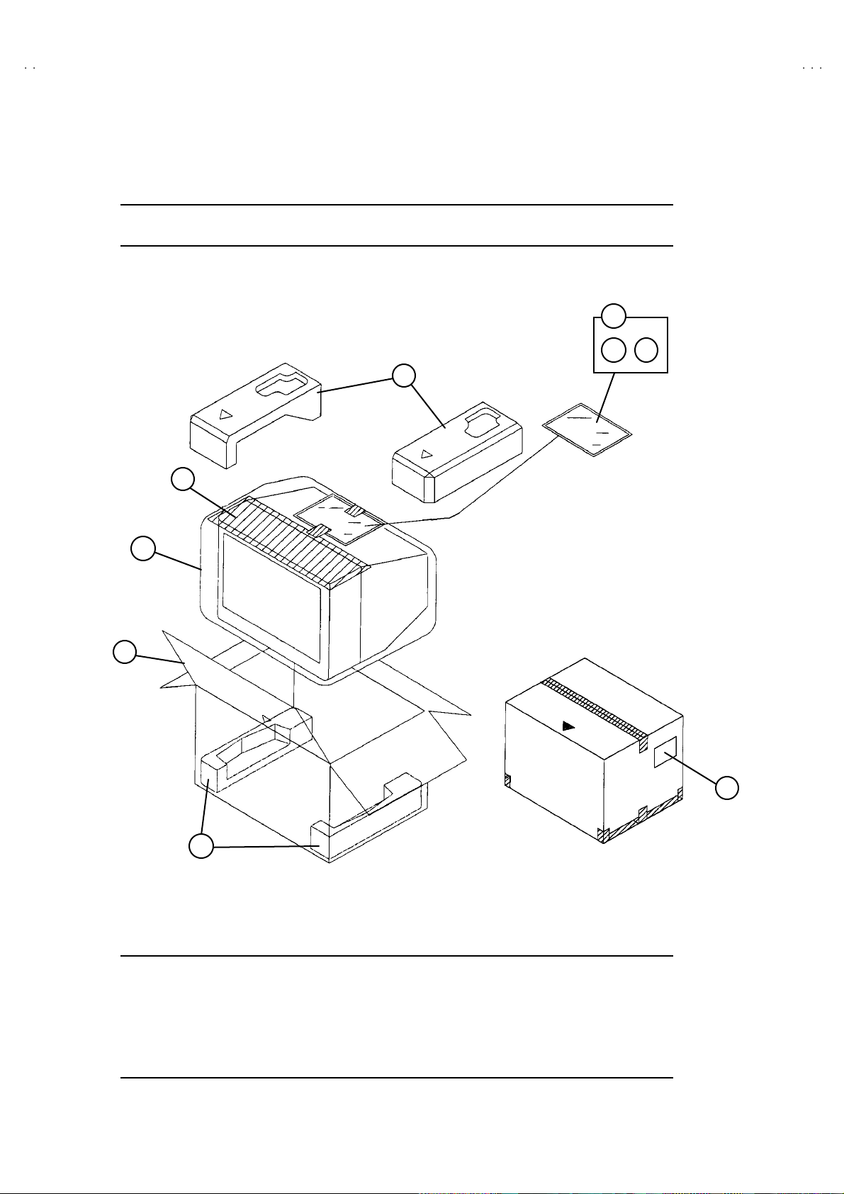
PACKING
4
1
5
!
6 7
2
3
8
2
PACKING PARTS LIST
Ref.No. Part No. Part Name Description
!
1 LC10058-017A PACKING CASE
2 LC10774-002A-D CUSHION ASSY 4pcs in 1set
3 CP30899-001-R TOP COVER
4 CP30897-004-R POLY BAG
5 CP30897-001-R POLY BAG
6 RM-C363-1H REMOCON UNIT
!
7 LCT1100-001A-D INST BOOK
8 CM36242-012-R POS LABEL
No. 51917
39
Page 11

VICTOR COMPANY OF J APAN, LIMITED
HOME AV NETWORK BUSINESS UNIT 12, 3-chome, Moriya-cho, Kanagawa-ku, Yokohama, Kanagawa-prefecture, 221-8528, Japan
4
T2922AR-CK #3
Printed in Japan
VP 0203
DP3051
Page 12
AV-T2922
STANDARD CIRCUIT DIAGRAM
NOTE ON USING CIRCUIT DIAGRAMS
1.SAFETY
The components identified by the symbol and shading are
critical for safety. For continued safety replace safety critical
components only with manufactures recommended parts.
2.SPECIFIED VOLTAGE AND WAVEFORM VALUES
The voltage and waveform values have been measured under the
following condition s.
(1)Input signal : Colour bar signal
(2)Setting positions of
each knob/button and
variable resistor
(3)Internal resistance of tester
:DC 20k
/V
(4)Oscilloscope sweeping time
:H
20µS/div
:V
5mS/div
:Others
Sweeping time is
specified
(5)Voltage values
:All DC voltage values
Since the voltage values of signal circuit vary to some extent
according to adjustments, use them as reference values.
3.INDICATION OF PARTS SYMBOL [EXAMPLE]
In the PW board
:R1209
R209
4.INDICATIONS ON THE CIRCUIT DIAGRAM
(1)Resistors
Resistance value
No unit :[
]
K
:[K
]
M
Rated allowable power
No indication :1/ 16 [W]
Others :As specified
Type
No indication
:Carbon resistor
OMR
:Oxide metal film resistor
MFR
:Metal film r esistor
MPR
:Metal plate resistor
UNFR
:Uninflammable resistor
FR
:Fusible resistor
Composition resistor 1/2 [W] is specified as 1/2S or Comp.
(2)Capacitors
: Original setting position
when shipped
5.NOT E FOR REPAIR ING SERVI CE
This mod el's power cir cuit is pa rtly diffe rent in th e GND. The
difference of the GND is shown by the LIVE : ( ) side GND and the
ISOLATED(NEUTRAL) : ( ) side GND.Therefore, care must be
taken for the following points.
(1)Do not touch the LIVE side GND or the LIVE side GND and the
ISOLATED(NEUTRAL) side GND simultaneously. If the above
caution is not respected, an electric shock may be caused.
Therefore, make sure that the power cord is surely removed from
the receptacle when, for example, the chassis is pulled out.
(2)Do not short between the LIVE side GND and ISOLATED(NEUTRAL)
side GND or never measure with a measuring apparatus measure
with a measuring apparatus ( oscilloscope, etc.) the LIVE side GND
and ISOLATED(NEUTRAL) side GND at the same time.
If the above precaution is not respected , a fuse or any parts will be broken.
Since the circuit diagram is a standard one, the ci rcuit and
circuit constants may be subject to change for improvement
without any not ice.
NOTE
Due improvement in performance, some part numbers show
in th e ci rcui t diag ram may not agre e wi th th ose i ndica ted i n
the part list.
When ordering parts, pl ease use t he numbers t hat appear
in the Par ts List.
Type
MM
:Metalized mylar capacitor
PP
:Polypropylene capacitor
MPP
:Metalized polypropylene capacitor
MF
:Metalized film capacitor
TF
:Thin film capacitor
BP
:Bipolar electrolytic capacitor
TAN
:Tantalum capacitor
(3)Coils
No unit
:[
µ
H]
Others
:As specified
(4)Power Supply
:B1
:9V
:5V
Respective voltage values are indicated
(5)Test point
:T est point
:Only test point display
(6)Conne cting method
:Connector
:Wrapping or solder ing
:Receptacle
(7)Ground symbol
:LIVE side ground
:ISOLATED(NEUTRAL) side ground
:EARTH ground
:DIGITAL ground
:[M ]
Capacitance value
1 or higher :[pF]
less than 1
:[µF]
Withstand voltage
No indication :DC50[V]
Others :DC withstand voltage [V]
AC indicated
:AC withstand voltage [V]
Electrolytic Capacitors
47/50[Example]:Capacitance value [µF]/withstand voltage[V]
No indication
:Ceramic capacitor
:B2 (12V)
AV-T2922
/AR
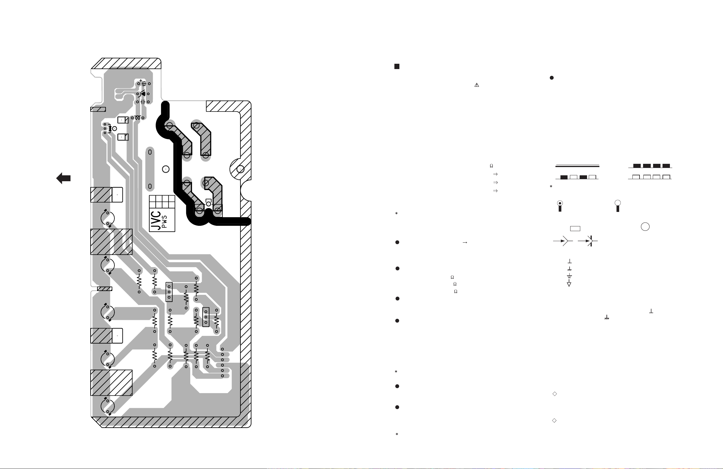
FRONT CONTROL PWB PATTERN
AV-T2922
FRONT
31
IC701
D702
S701S702S703S704S705
C701
D701
C702
L701
-1
Group No.
UL MARK
CKF1269-
PW
12
S901
1
NOZAKI
00.01.28
LIVE
2
P
2-12
MENU CH - CH + VOL - VOL +
R712
R706
R703
R702
Q701
BE
R710
R713
R705
R709
R711
R707
EB
R704
Q702
R701
R708
61
No.51917
ISOLATED
N
VP0203
DP6060
Mar. 2002 No. 51917
Page 13
AV-T2922
CONTENTS
AV-T2922
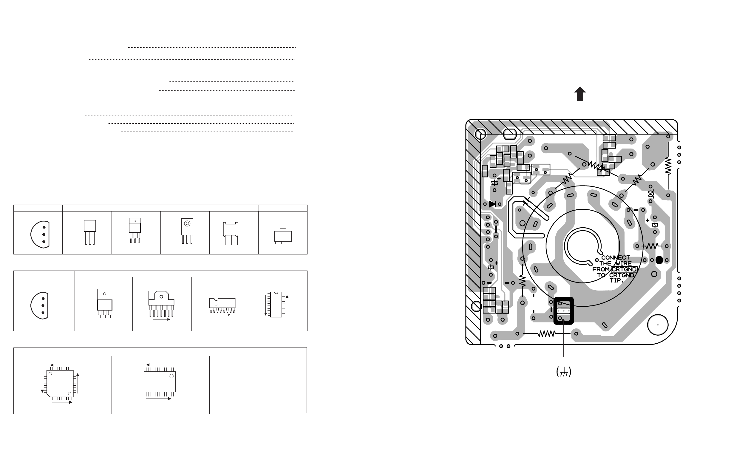
CRT SOCKET PWB PATTERN
SEMICONDUCTOR SHAPES
BLOCK DIAGRA M
CIRCUIT DIAGRAMS
MAIN & FRONT CONTROL PWB CIRCUIT DIAGRAM
MAIN & CRT SOCKET PWB CIRCUIT DIAGRAM
P ATTERN DIAGRAMS
MAIN PWB PATTERN
CRT SOCKET PWB PATTERN
FRONT CONTROL PWB PATTERN
SEMICONDUCTOR SHAPES
TRANSISTOR
BOTTOM VIEW
E
C
B
ECB
(G)(D)(S)
IC
B O TT OM VI EW F R O NT V IEW TO P VI EW
BCE
FRONT VIEW
ECB
ECB
TO P VI EW
CHIP TR
C
BE
2-2
2-3
2-5
2-7
2-9
2-11
2-12
R367
R358
W412
C342
D341
5
C357
R352
C355
1
C3
R342
MARK
W049
SCREEN
T
R357
C354
R354
R366
52
R355
R341
E
Q341
R343
TP-R
C382
GK
B
G2
G1
C
Q352
Q342
RK
TOP
R361
HE
R364
R353
C353
H
R359
R368
BK
C356
R356
B
C
E
Q353
R362
R365
L381
Y003
E
4
C381
R381
U
MARK
1
E1
CHIP IC
OUT
E
IN
IN OUTE
1 N
1 N
W050
1
N
E
C
C351
Q351
R351
B
R360
Y001
Y002
R363
SK351
TP-E
UL MARK
CKF0866-
Group No.
/2!
-1
TOP VIEW
N
N
N
1
N
1
N
TP-E
2-2
No.51917No.51917
2-11
Page 14
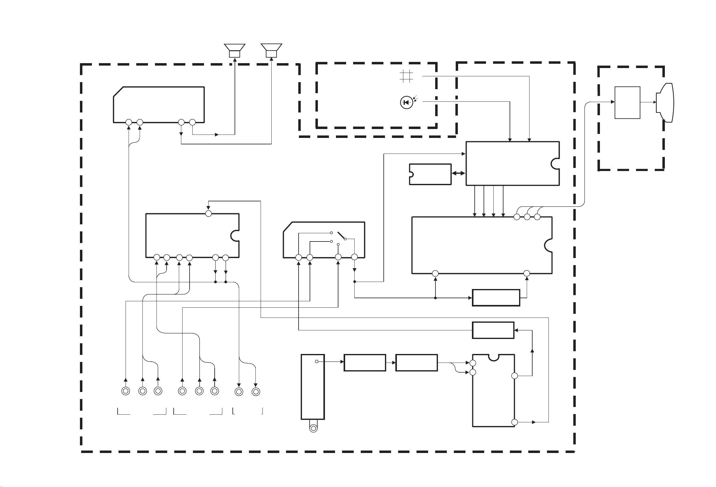
R.G.B.
OUT
V01
CRT
SP(L)
CONTROL PWB
IC702
MEMORY
IC701
MICRO COMPUTER
IC201
V/C & DEF
15 1614
CRT SOCKET
PWB
42
45
C
VIDEO
REMOCON
Q201, Q202
BUFFER
Q131
BUFFER
IC101
18
10
4
5
SF101
SAW F.
Q101
AMP
IF
IC701
KEY
R
G
B
OUT
C V IN
V. OUT
FM. OUT
SP(R)
IC601
AUDIO AMP
1 2 11 13
RL
LR
IN OUT
IC251
VIDEO SW
1 4
6 8
R2
V2
L2R1
V1
L1
RL
INPUT 1
INPUT 2
OUT PUT
(VARIABLE)
IC651
MTS & TONE/VOL CONT.
36
37 38
39
25
26
7
R
L
OUT
R1 L1
IN
R2 L2
IN
V1
V TV V2
YS.
R. G. B.
ANT INPUT
TU001
TUNER
MAIN PWB
BLOCK DIAGRAM
AV-T2922
AV-T2922
No.51917
2-3 2-4
No.51917
Page 15
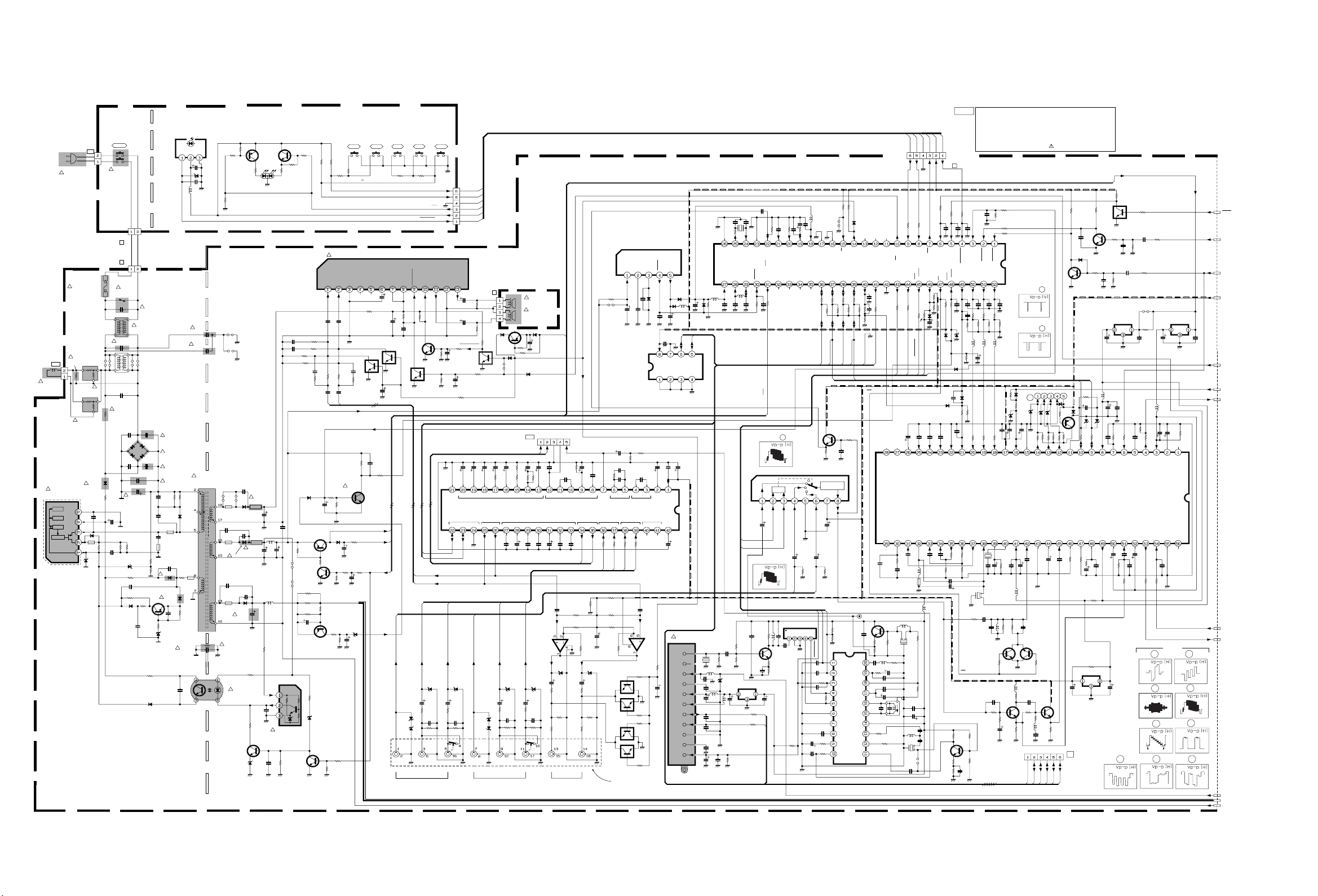
CIRCUIT DIAGRAMS MAIN & FRONT CONTROL PWB CIRCUIT DIAGRAM
FRONT CONTROL PWB
Q701
2SA933AS/QR/-T
4.2V
R712
560
1/2W
C953
QCZ0122-561
Y910
D948
RU3YX-LFC4
QCB32HK-561Z
C943
560p
ICP-N50-Y
D942
QCZ0325-561
C941
560p 2KV
D941
!
C942
100/160
PC921
R959
0
11.2V
D945
560p
! CP942
470/16
R948
1.5k
4.9V
4.8V
(RED) (GREEN)
:POWER :TIMER
SPR-39MVWFD702
!
CP941
ICP-N75-Y
C952
1000/25
QETN1EM
-108Z
C957
470p
QQL26AK-820Z
L942
C944
1000/16
L941
QQL26AK-820Z
R941
15
1/2W
129.4V
11.2V
C949
OPT
Q944
*2
0V
C954
OPT
Q702
2SC1740S/QR/-T
0V
R709
560
1/2W
A-Vcc
C945
82
!
IC941
SE130N
ERROR AMP
R952
4.7k
C606
A-GND
R707
22k
1/2W
0V
R708
22k
1/2W
OPT
C603
OPT
R605
820
2SA966/OY/-T
R942
22k
Y945
BW
Y943
BW
1.2 2WMFR
100/16
2SA949/Y/Z1-T
.47/50
820R609
C621
OPT
R615
C624
.47/50
D962
*5
C511
10/50
Q941
LOW-B SW
12.8V
12V
Q942
*2
R961
1.2 2WMFR
R962
R963
OPT
(1/2W)
C961
129.4V
Q961
B1-GND
R951
3.3k
D944
BW
Q943
0V
SGA-4005A-R2
IN
CH2
1.2V
C604
BP
R603
6.8k
C623
.47/50
STB12V
!
Q511
0.1V
R512
10k
C946
100/25
R945
3.3k
R944
10k
C947
10/50
MTZJ7.5A-T2
R706
10k
1/2W
S701
S705 : QSW0619-003Z
BTL IN
GND
NC
NC
QRT039J-2R2
.47/50
C620
OPT
R614OPT
OPT
BP
R514
33k
4.4V
0V
R947
BW
R946
12k
B1
D961
C962
47/50
R621
2.2
Q605
3W
*10
VOL-VOL+
OUT
BTL
NC
0V
P_ON/OFF
C512
OPT
C609
100/16
C613
1000/25
Q604
0V
R513
0
HD_VCC
H_VCC
R704
R701
10k
10k
1/2W
1/2W
R705
5.6k
1/2W
!
IC601
CH1 IN
1.2V
C607
BP
OPTR608
OPTR604
R607
6.8k
BP
RL
2SC2785/JH/-T
R510
0
12.7V
D943
*5
R943
1.5k
1/2W
0.1V
0.5V
R964
2.7k
1/2W
129V
R965
47k
1/2W
0V
R966
22k
1/2W
*2
R949
15k
0.5V
R950
10k
CH-CH+
MENU
S705
S704S703S702S701
R702
R703
5.6k 1/2W
10k 1/2W
KEY1
KEY2
T-ON/OFF
STB5V
REMOCON
CN00N
AUDIO AMPLA4485
OUT
CH2
GND
MUTE
STAND-BY
Vcc
Vcc
FILTER
10.7V
21.5V
C618
0.22
TF
*10
-0.1V
C622
1/50
OCP
V1
D255
*6
D256
*6
V1 V2L1 L2 L RR2
VIDEO
10V
2.1V
0V
C615
R620
18k
(L/MONO)
INPUT 1 INPUT 2
1000/25
R611
22k
C617
1000/25
Q601
0V
*2
0V
R613
33k
R612
C610
OPT
OPT
Q602
OPT
R624
OPT
R626
8.2K
C668
1/50
A-GND
SDA
2.4V 2.5V
SDA1
SCL1
L
R
R1
L1
D692
D691
*6
*6
C692
C691
10/50
10/50
R691
R692
1k
1k
C693
C694
3900p
3900p
R693
R694
OPT
OPT
R1
CN0PW
PW
POWER CORD
!
QMPR150-200-JC
FUSE
F901
QMF51E2-3R15J4!
Y905
!
R905
68 15W UNFR
QRF154J-680
QAD0101-9R0
!
RGP10J-5025-T3
GND
Vcc
D929
TH902
QAD0101-9R0
! D903
0V
18.5V
158.4V
0V
K923
QQR0582
-001Z
2.3V
R921
1/2W
*9
BW
Y906
BW
!TH901
D928
*5
680
!
L01
CNDEG
DEG
DEG-COIL
CELD058
-001J3
!
IC921
STR-F6654
OVP
TSD
OSC
DRIVE
MAIN PWB
SGA-1020A-R2
POWER
!
S901
QSP4K21-C01
CN00P
P
P
CN00P
!
VA901
ERZV10V621CS
! C902
0.1 275VAC QFZ9072-104
C907
OPT
!
4.7 15W
R901
QRF154K-4R7
C908
OPT
C909
OPT
!
R902
39k
C906
3WOMR
QEZ0371-337
QCZ0122-391C931
C924
470/35
R922
0.15 2WMFR
C922
470p
QCS31HJ-471Z
D905
MTZJ6.8A-T2
D924
C926
0.0022
LIVE
! LF901
QQR0676-001
330/400
R923
0.15 2WMFR
BWR928
OPTC927
OPTR927
*5
MY
! C901
.1 AC275V
QFZ9072-104
Y907
BW
Y908
BW
R911
18k
1/4W
R926
1.5k
1/2W
ISOLATED
LF902
OPT
R910
560k
1/2W
RGP10J-5025-T3
RGP10J-5025-T3
8.7V
8.4V
R925
1k
1/2W
R929
3.3k 1/2W
D927
*5
C702
QCB32HK
-561Z
! C903
.0047 AC250V
QCZ9074-472
! D901
GSIB460
! C904
.0047 AC250V
QCZ9074-472
!
C905
.0047 AC250V
QCZ9074-472
C929
OPT
R933
OPT
C930
OPT
K921
QQR0582-001Z
C921
2200p 2KV
QCZ0325-222
K922
BW
C923
OPT
! D921
! D922
8.9V
C925
MY
0.001
Q921
2SA933AS/QR/-T
D923
*9
.0022 AC250V
QCZ9075-222
C928
0.1
MY
OUT Vcc GND
4.9V
C981
470p AC250V
QCZ9075-471
C983
470p AC250V
QCZ9075-471
R932
4.7 1/2W
!
C982
IC701
PIC-37243SR
REMOCON
RECEIVER
C701
4.9V
47/16
D701
OPT
L701
QQL03BJ
-560Z
R713
LIVE ISOLATED
!
!
R930
OPT
D926
OPT
K924
BW
R924
10k
1/2W
17.4V
2.1V
! T921
SW TRANSF
CETS090-001J8
Y912
Y913
OPT
Y911
BW
K943
QQR0582
-001Z
C955
OPT
K942
QQR0582
-001Z
RGP10J-5025-T3
C956
OPT
K941
QQR0582
-001Z
RU3AM-LFC4
QEZ0203-107
R981
!
8.2M 1W
QRZ0057-825
12.2V
TLP621/GR/
MTZJ5.1B-T2
R711
22k
1/2W
R710
22k
1/2W
10k
BW
!
!
AV-T2922
OUT
CH1
CN00S
9.8V
MUTE-MIX1
C619
OPT
SCL
S
R617
(1K)
OPT
R619
(1K)
OPT
R622
18k
14.1V 4.9V
Q603
*4
R623
OPT
!
SP01
R
CEBSS12D-04KJ2
!
SP02
L
CEBSS12D-04KJ2
-3.1V
12.5V
HD_VCC
D632
*5
Q631
*1
0V
Y601
D634
BW
*5
D631
*5
R632
C631
47/25
OPT
R631
47k
D633
*5
FR720
Y704
OPT
BW
MUTE-MIX1
MPX
TVL
TVR
GND
SOA
NRVA02D-152X
NRVA02D-153X
C664
10/16
TAN
R658
15k
5.2V
CNMPX
R656
C663
1.5k
1/50
TAN
R655
3.3k
1.1V
4.6V
R656
R658
C665
C667
1/50
33/50
C666
R660
1/50
5.1k
4.5V
2.8V
4.6V 4.6V
IC651
VARIABLE
LINEIIC BUS
4.6V
4.6V
4.6V 4.6V 4.6V
4.6V
C677
0.022
V2
L2
D253
*6
D254
*6
(L/MONO)
VIDEOAUDIO AUDIO AUDIO
C671
2.2/50
D657*6D656
*6
C686
10/50
R672
1k
C638
3900p
R684
OPT
C672
0.0022
R2
C673
IC652
BA15218N
AMP
C685
10/50
R671
1k
C637
3900p
R683
OPT
COM
TVL
TVR
C661
0.1
MY
4.5V
SAP DEMODULATIONdbx NR
UPC1851BCU
4.6V
0.0022
C674
4.5V
C683
4.7/50
R670
R674
R676
180
4.5V
SI1SOASTISRBITIWTIWRBdo2VO F
4.6V
C675
C669
1/50
BP
4.5V
D655
OPT
470
82k
OUTPUT
(VARIABLE)
.47/50
R682
68k
C660
0.1 MY
3.1V
4.6V 4.6V 4.6V
C676
0.1 MY
R662
12k
R663
12k
4.5V
C659
TVR
R666
5.6k
R661
47k
D653
C682
4.7/50
R669
470
R673
R675
C662
3.3/16
R654
33k
5.2V
MTS & TONE/VOL CONTROL
0.1 MY
2.2/50
(1/2)
C658
0.047
R651
1k
4.6V
TVL
R688
0
R2
R667
5.6k
R664
12k
R665
12k
C680
47/25
R668
47k
OPT
Q651
*10
Q652
*10
82k
Q653
180
C709
47/25
C657
2.2/50
PILOT
4.6V
R687
0
L2
0V
*10
0V
Q654
*10
J001
QNN0086-001
REAR AV JACK
IC703
L78LR05E-MA
5V REG & RESET
CD
INPUT
5.9V
12.7V
C730
C710
OPT
0.1
MY
R652
560
R653
2.7k
C655
47/25
4.7/50
BP
C656
1/50
DET
PHASE
ER1EL2ER2TVLTVRLBCLTCTLORBCRTCTROSURLOTROTD-GND
4.6V 4.6V
R6860R685
0
R1
L1
C670
1/50
BP
4.5V
4.5V
IC652
AMP
(2/2)
4.5V
R678
0V
22k
R679
22k
0V
0V
R680
22k
0V
R681
22k
AV-T2922
GND
RESET5VOUTPUT
0V
D709
BW
D702
BW
C711
0.01
C722
0.01
DD
V
A0A1A2
IC702
AT24C02-T2922AR
MEMORY
C651
0.01
C653
C654
0.1 MY
VRE
PD1PD2d01 PHD1PHD2COMSDTNDTSOT
Vcc
9V
1/2
DET
Vcc
FIXED
LINE OUTEXT1 ININEXT2TV OUTOUT TONE/SURROUND
MOAFOLFOREL1
4.4V
NCNC
TU001
R677
6.8k
C684
10/50
IF2
TU
4.9V4.9V
D706
BW
L703
BW
C712
100/16
SCL2
4.9V
NP
SCL
C652
100/16
C679
1/50
!
TUNER QAU0229-001
IF1
NC
33V
BT
NC
BP
BM
SDA
SCL
SAS
NC
AGC
ANT INPUT
100/16
C713
SDA2
4.9V
SDA
Vss
0V
32.2V
10/50
STB5V
SP-ON/OFF
A-MUTE
AVCC
CV-IN
X701
QAX0468-001Z
CRYSTRL
L702
D708
4.7
OPT
R758
L704 ;
CELP055-8R2Z
CF001
QAX0349-001
47.25MHz
0.01
C011
C010
OPT
L001
15
C007
470/16
C006
OPT
C005
OPT
C003
OPT
C001
:
NOTE
*1
:
2SA1037AK/QR/-X
*2
:
2SC2412K/QR/-X
*3
:
DTA124EKA-X
*4
:
DTC124EKA-X
*5
:
1SS133-T2
*6
:
MTZJ9.1C-T2
*7 :
MTZJ5.6A-T2
MTZJ7.5B-T2
*8 :
CN00N
N
R718
R776
OPT
C766
.47/50
C761
C707
18p
CH
C708
22p
CH
R773
0
2.1V
2.2V
Vss
X IN
X OUT
DD
OSC1
OSC2
V
4.9V
4.9V
4.9V
L704
8.2
C714
OPT
R721
0.1
MY
C715
C716
15p
47p
CH
CH
C762
BP
1/50
220p CH
L701
4.7
C763
C706
0.1
0.001
R764
1M
2.2V
CV IN
CNVss
RESET
PW_ON/OFF
4.9V
4.8V
R722
1k
560
C717
150p
CH
MY
R761
R762
1k
15k
2.2V
2.2V
0.7V
4.9V
HLF
AVcc
RVCO
VHOLDNC
NC
NC
NC
R724
220
SDA2
3.3k
Y701
0
D703
*5
NC
NC
NC
0V
0V
H/S
IIC
A-MUTE
SDA2
SDA1
SCL2
SCL1
2.4V
2.4V
4.9V
4.9V
R726
R728
R730
R731
220
220
220
6.8k
R729
R727
R725
6.8k
6.8k
6.8k
SDA1
SCL2
SCL1
CTL_GND
Ym
0V
TV/EXT
BUS
FREE
0V
C728
OPT
R732
6.8k
OPTC729
2.2kR754
2.2kR755
BUS_FREE
0V
SP-ON/OFF
SEL1
0V
R774
1k
SEL1
SEL2
P_ON/OFF
9.1V
R765
3.4V
VIDEO SW
3.8V
V2
AGC_MUTE
C113
C114
R113
C124
R114
OPT
C116
0.22
R161
3.3k
6dB AMP &
75Ω DRIVE
IN3
100/16
C251
10/50
AGC_ADJ.
0.01
0.01
100
0.01
R162
0
C256
4.2V
9.1V
R251
RF_AFC
2.8V
1.5V
R766
1k
Vcc
75
OUT
4V
R111
390k
R112
330k
IC101
M52342SP
2.1V
RF AGC
DELAY
4.7V
AFT
OUT
1.6V
RFAGC
OUT
VIF
1.4V
IN
VIF
1.4V
IN
INTER
SW
IF AGC
FILTER
FM F/B
FM OUT
1.2k
C765
100p
CH
TP-12B
C123
0.01
EQ
APC
V.OUT
VCC.F
VCO
VCOGND
VCC
SIF
OUT
SIF
SW
SIF
IN
IC251 8
2.3
IN1AB
3.6V
C255
10/50
SEL2
SEL1
TP126
1.2
VTV
L101
0.22
R103
100
C105
1/2W
0.01
R101
C101
0.01
R006
82
4.7L003
D001
MTZJ33A-T2
L002
OPT
C002
OPT
9.1V
5.6k
1.7V
Q101
R102
1.8k
4.9V
C008
47/25
SDA1
SCL1
R001
56k
2SC5083/L-P/-T
1V
R104
C102
R105
0.01
AN7805FIC001
9.1V
INOUT
C009
47/25
560R004
R003
560
CTRL
0V
18
27
C103
OPT
BA7612NIC251
IN2
0V 3.8V
V1
SF101
QAX0324-002
C104
0.01
R170
68k
Q761
*2
MUTE
GND
C252
10/50
R252
75
C161
10/50
C162
OPT
9.1V
0.9V
1.5V
3.4V
4.9V
C312
0.01
2.1V
4V
OPT
4V
9.1V
2.2V
0V
2.1V
MY
Q131
*2
R1341kR133
R135
C121
OPT
R116
68
C122
R164
1k
T111
4.7/50
NC
DACVM OUT
IC201
TB1230N
V/C&DEF IC
NC
R311
27k
C311
0.33
TF
L131
22
1.5V
270
470
L112
OPT
C120
.47/50
680p CHC119
0.01C118
C117
47/25
CELT001-209J3
10kR163
CF161
SFSH4.5MCB
C313
NC
Color
FSC OUT
Filter
APC
2..9V 2..1V0V2..3V
C214
0.1
MY
L302
K301
CF131
QAX0339-001
CF131
R117
OPT
R131
C163
47p
L161
22
C164
47p
Y161
C166
0.01
R7161kR717
1k
4.9V 4.9V 0V
KEY-1
KEY-2
MUTE
SEL2
AGC
0V
R736
47k
R775
R737
1k
68k
R734
1k
R735
47k
D704
C719
10/50
AGC_MUTE
AGC_ADJ.
C813
0.01
2.5V
4.5V
B-IN
Limiter
Analog
GND
Y-I N
Fsc
C308
0.1
MY
BW
BW
L113
BW
R132
330
1k
C112
0.01
C111
47/25
CH
CH
OPT
R733
OPT
R749
1k
C718
0
0V 0V
SD
T-ON/OFF
ADJ.
AGC
TV/EXT
X-RAY
0.8V1.7V
1kR748
5.6kR738
*5
D705
OPT
C779
10p
CH
D712
*5
C812
C811
0.01
0.01
4.5V 4.6V 0V0V
R-IN
G-IN
Analog
Analog
B-Y IN
R-Y IN
2..3V
C309
0.1 MY
R315
OPT
R167
1k
6.4V
R168
100
R169
560
R713
1k
C705
C723
470p
OPT
CH
2.3V 4.5V
4.9V
NECK
RF AFC
REMOCON
/OCP
BGR
Ys
0V
0V0V
4.4V
C724
C725
C720
OPT
OPT
150p
CH
R7421kR7441kR746
R740
1k
100
C721
OPT
R743
R741
3.9k
10k
D710
*7
L706BWL707
R799
BW
33K
D510
*5
D713
*5
R756
10k
R815
0
R8130R812
0
C815
OPT
0V 0V 0V
Ys
B-IN
Ys/Ym
Digital
Analog
Digital
R-Y OUT
B-Y OUT
Y-O UT
2.2V
1.7V
1.7V
R312
X301
0
R314
*
0
C305
12p
R313
CH
OPT
0.01C307
47/25C306
R301
1K
TV/EXT
R165
27k
Q161
*2
2.3V
1.7V
R166
10K
C165
0.01
C301
CH
C303
12p
CH
C704
0.01
V-SYNC
0V
C726
OPT
R745
3.9k
C773
1/50
R811
0
G-IN
Digital
Vdd
Fsc
5V 2.7V
C213
1/50
X301;
QAX0305-001Z
EF301
CE42142-222Z
L301
39
Q302
*2
R303
5.6k
C201
OPT
R201
820
R202
1k
C202
100/16
R711
120k
R712
180k
R710
1k
R705
4.5V
1k
H-SYNC
IC701
M37267M8-100SP
MICRO COMPUTER
0V
C727
OPT
R747
3.9k
L708
BW
RF_AFC
R217
56k
R216
0
C806
0.01
C805
9.1V 6.5V
Digital R-IN
RGB-Vcc(9V)
(TEXT)
Stretch
Black
16.2MHz CRYSTAL
4V
R215
C210
820k
0.01
L205
4.7
R307
4.7k
R308
6.8k
0V
L201
0
R220
470
Q201
*2
4V
3.4V
R203
820
D201
*5
D202
*8
220/16
ABCL
Y/C-Vcc(5V)
4.8V
C304
0.01
0V
7.1V
IC701 1
5
IC701 2
5
CN00T
D801
*11
C215
C209
220/16
C205
68p CH
R204
R221
L202
C206
10/50
680
OPT
OPT
OPT
CTL_GND
CRT SOCKET PWB
T
R801
220
(TEXT)
GND
Chroma IN
2.3V
C30215p
15p
CH
Q301
SCL1
*9
*10 :
*11
BW
0 : QRSA08J-0R0YL
OPT::
G
RB
GND
*11D802
*11D803
R816
R817
OPT
OPT
220
R802
2.5V
2.3V
R-OUT
G-OUT
(Y/C)
APL
GND
2.2V
C207
0.1
MY
C208
4.7/50
*2
0V
R304
5.6k
Q202
*2
9.1V
3.4V
2.8V
R205
1.5k
CONTROLEXT
SDA1
SCL2
SDA2
MTZJ15A-T2
DTC323TK-X
: MTZJ15B-T2
:
BUS WIRE
NON-MOUNT(OPEN)
SAFETY PARTS
R704
10k
C703
1000p
D701
*5
4.5V
Q701
*2
9V
D805
OPTD804
*11
R819
OPT
OPT
R818
OPT
Q801
220
R803
0V
2.2V
B-OUT
(Digital)
GND
Video-IN
Composite
S-Inhibit
2.1V
1.5V
R309
R401
10k
10k
9.1V
C291
100/16
C CN00C
BUS_FREE
R709
10k
Q702
4.5V
R703
0
0.1V
C701
0.001
CH
SCL1
SDA1
R820
OPT
C814
OPT
D772
*7
D771
*7
R772
R771
220
220
2.4V
2.5V5V4.4V 1.3V
SCL
SDA
V Center
AFC1-filter
5.1V
2.6V
R505
C506
8.2k
0.01
C507
1/50
R218
OPT
R291
OPT
(2W)
IN OUT
C292
100/16
IC291
AN78N05
5V REG.
H_VCC
R714
10k
Q703
0V
*4
R715
220K
1.9V
*2
47/25
0.1V
L771
4.7
C771
C505
(Digital)
Vdd(5V)
Sync-OUT
0.7V
C402
1/50
R708
0
C702
OPT
R702
22k
IC293
AN78L05-T
5V REG.
5V
C296
100/16
R504
0.01
100k
Coinsident Det
V-Sepa
5.3V
C212
0.1
R214
OPT
R213
390
C780
0
INOUT
C772
0.01
R503
FBP-IN
Sync-IN
2.3V
C211
680p
C781
0
R707
10k
R701
56k
Y201
NRSA02J-0R0X
11.9V
R940
OPT
C295
OPT
R502
OPT
10k
R501
0
C503
0.01
1.9V
4.5V
Curve
H-OUT
Correction
V-ram p
V-OUT
0.5V
4.5V
C404
C403
OPT
2.2/50 HF
QEM61EK-225Z
CH
R403
R402
6.8k
0.6
4.9V
0.8 1.5
1
12 13 14
3.2
3.4 4
R706
0
34
42
31
56k
100/16
8.9V 2.5V
H Vcc
V-NF
4.4V
8.9V
L501
4.7
C501
IC292
AN78L09-T
9V REG.
OUT IN
C294
100/16
C401
VAGC-filter
(DEF)
GND
IC201
1/50
NC
SCP OUT
V-BLK OUT
NC
0.7
NECK
VP
HP
9V
11.9V
C293
OPT
X_RAY
ABL
HD
R506
1K
NFB
VD
33
45
4
5
BT
B1
B1_GND
No.51917 No.51917
2-5 2-6
Page 16

MAIN & CRT SOCKET PWB CIRCUIT DIAGRAM
Q521 D
200
3.8
IC401
2 3 7
50 25 1
R410
0
C405
R411
0.1
OPT
MY
0.4V
R404
1K
NECK
VP
R529
620
R521
2.2K
3WOMR
BSN304-T
H-DRIVE
1.5V
R523
2.2K
4 5
R406
4.7K
R408
4.7K
R407
R405
3.9K
220
4.3V
Q401
*2
VD
NFB
R532
2.2K 3WOMR
T521
CE42034-002
H-DRIVE TRANSF
C523
1/160
Q521
QCB32HK-151Z
72.2V
R423
10K
-0.1V
R533
22
1/2W
C521
150P
500V
10K
THERMAL
PROTECTION
OUT PUT
GND OUT IN
C406
0.01
MY
C407
OPT
D402
MTZJ75-T2
R419
18K
!
Q522
2SD2499-LB
H.OUT
K521
BW
D512
RH3G-F1
C522
330P
500V
QCB32HK-331Z
R524
1/2W
LA7840IC401
DRIVE PUMP UP
16.1V 27.2V
2.1V 2.1V
K401
QQR0621-001Z
OPTR420
R418
56K
R422
0
C414
1/50
HP
ABL
X_RAY
C524
1.5k MPP
QFZ0198-133
QFLC2AK-333Z
R421
0
R417
OPT
!
.013
!
C525
0.47
QFZ0119-474
2
OSC STOP
Vcc
26.2V
C415
0.0015
MY
100V MY
56kR416
V-LIN
2200/35
QETM1VM-228
200VMPP
Q522 B
2.7V
C410
100/35
D401
1N4003-T2
C411
470/35
C412
0.33
C413
R414
0.68
1W
R525
560 1W OMR
!
L521
QQR1137-002
R526
1.5k 2W
QRL029J-152
R415
R412
2.7
1/2W
R545
OPT
VH
H-LIN
OMR
R413
560
1/2W
Y401
1K 1/2W
BW
Y402
OPT
S401
OPT
V.CENTER
DOWN
UP
SW
CENT
NCNC
!
DY001
(ITC)
DEF YOKE
HV
CN0HV
1200
1000/35
QETM1VM-108
MTZJ9.1B-T2
D583
OPT
C545
1000/35
QETM1VM-108
C543
R581
1/2w
R584
1/2W
27k
22k
! FR542
.56 2W
QRZ9024-R56
D582
FR543
!
2.2 2W
QRZ9023-2R2
! D562
MTZJ7.5S-T2
AV-T2922
QCB32HK-821Z
QRE121J-682Y
C584
0.1 MY100V
QFLC2AJ-104Z
QCB32HK-821Z
RGP10J-5025-T3
R582
39k
1/2w
R583
OPT
C583
0.1
MY
C561
100/35
!D542
RU3AM-LFC4
FR586
6.8K
C544
820p
!D543
T522
QQH0115-001
C542
820p
500V
135 23
80
D561
1SS81-T2
!
FR561
4.7
QRZ9017-4R7
!
R562
MFR 1/4W
6.34K
QRA14CF-6341Y
!
R563
3.24K
MFR 1/4W
QRA14CF-3241Y
!
4
6
FR585 2.2 1W
!
L581
OPT
1/4W
X-RAY
HVT
AV-T2922
!
C526
100/160
QEZ0203-107
T522
250
QRZ9021-2R2
CN00X
X
ANODE
FOCUS
SCREEN
C581
0.047
MY
!D581
RGP10J-5025-T3
C548
820p
QCZ0122-821
D544
D541
RH1S-T3
33/250
QETM2EM-336
5
8
2WOMR
RH1S-T3
C541
R544
22K
BT
R546
OPT
TP-91(B1)
TP-E
B1
NC
GND
B1
CN0B1
R343
R342
33K
R341
120
33K
R353
150
C352
*1
:
*2
:
*3
:
*4
:
*5
:
*6
:
C342
3.3/50
D341
*5
CN10T
T
GND
CN00U
U
HB
NC
GND
HEATER
C357
100/16
9V
B
G
R
NOTE
Q341
*2
2.2V
C353
OPT
R368
2.7k
2WOMR
R352
150
2.4V
OPT
R366
2WOMR
2.7k
R351
150
2.3V
C351
OPT
Y001
OPT
Q353 C
80
2SA1037AK/QR/-X
2SC2412K/QR/-X
DTA124EKA-X
DTC124EKA-X
1SS133-T2
MTZJ9.1C-T2
Q342
*2
R364
R367
2.7k
R363
1.8V
12k
2V
12k
1.9V
R365
12k
2W OMR
146.5V
Q353
2SC4544-LB
C356
330p CH
R356
330
139.6V
Q352
2SC4544-LB
C355
270p CH
R355
330
143V
Q351
2SC4544-LB
C354
270p CH
R354
330
(10/250)
Q352 C
110
CRT SOCKET
! SK351
CE42535-001J1
R362
1.5k
1/2W
B.OUT
R359
TP-R
100
R361
1.5k
1/2W
R.OUT
R358
100
R360
1.5k
1/2W
L381
G.OUT
39
R381
OPT
R357
100
OPTC381
NC
80
BW
::BUS WIRE
0 : NRSA02J-0R0X
NON-MOUNT(OPEN)
OPT
: SAFETY PARTS
!
V01
Y002
TP-E
OPT
A68AJB82X02
R
G
B
G1 G2 G3
Y003
OPT
!
C382
.001
QCZ0121-102
BK
RK
GK
H
H
CRT SOCKET
PWB
(Within MAIN PWB)
SGA-1020A-R2
CN10U
U
Q351 C
E1
FOCUS
SCREEN
3KV
(2/2)
9.1V
C547
1000/16
VP
NECK
HP
ABL
NFB
X_RAY
HD
9V
VD
No.51917
12.4V
INOUT
IC541
AN7809F
9V REGULATOR
C546
220/16
MAIN PWB
SAG-1020A-R2
2-7 2-8
(1/2)
B1
BT
B1_GND
MAIN PWB
No.51917
Page 17

AV-T2922
AV-T2922
PATTERN DIAGRAMS MAIN PWB PATTERN
R929
W313
K922
43
C905
C908
R910
W312
C921
C931
W307
L
PC921
W306
2
R933
R948
R951
R928
1
K921
C929
C930
C923
D921
R932
K924
R949
C903
W331
R981
R950
D926
D901
R930
Q943
W330
T921
W320
8
7
5
4
3
2
C904
R952
M
9
D923
C926
8
D924
C924
4
7
R921
2
K923
C922
D929
W308 W310
6
5
4
C927
D928
R926
R925
D927
R927
R924
R922
R923
C906
W314
C928
BCE
Q921
C925
D922
IC921
531
D905
R911
POWER
SHOCK HAZARD
W309
H005
FRONT
C909
TH902
3
LIVE
W305
Y905
Y906
R905
F901
2
TH901
1
DEG
P
21
T3.15AL 250V
M
2
1
0
R901
C907
LF902
W376
C902
LF901
VA901
LK
C901
C954
D944
R902
D903
C942
C983
Q944
Y907
R959
Y908
C981
C982
Y912
D945
Y913
C949
TP-E
R684
C638
R675
R673
R672
14
W0
64
9
R678
Q651
R679 R680 R681
Q652
R6
77
R668
C684
W060
R664
W391
C676
4025
W070
W071
R685
R686
R687
R688
C658
C654
R651
C653
R652
W033
W352
W369
R220
1
W074
TVL
Q201
R203
R304
W024
R201
C201
R204
R202
C202
W343
L205
R218
C209
C207
C208
W086
R401
45
R309
W202
R504
C505
C772
10
R771
R772
R820
W028
5
W409
D713
C779
W378
D708
L702
R721
R758
D706
C713
W333
W030
GH
W055
R669
R674
W054
R670
R676
13
W061
R003
Q654
R004
Q653
C682
C683
D655
8
R6
67
R665
50 55
C506
C814
D712
D653
C679
W390
42
W389
W069
W052
C651
W066
C205
C507
R505
C212
W399
W347
W051
L201
520
C715
W706
C652
W119
R502
L704
W396
R221
C716
R214
D772
C708
IC201
C503
W375
27
C717
L771
26
C707
Q202
W201
R501
C771
W702
C211
CF131
VCO
R135
R205
C206
C402
56
1
C113
W388
L131
W058
W382
W114
W400
R764
C761
W329
1
W075
R503
D771
D804
C714
R773
X701
GF
IJK
12
615
C670
22
21 20
C667
W205
C813
R813
C766
5
C691
25
W365
R756
1
C665
W403
W342
R301
W413
Y704
R694
R660
C668
R315
R314
D201
FR720
D253
W067
C664
8
W715
C812
C709
J001
8
11
C694
R692
4
C637
3
W065
C685
W712
D254
D691
C680
R666
W056
R6
63
IC652
C671
C673
C672
C677
W348
15 10 5
R658
R655
R656
C663
C661
C662
R682
W009
5
MPX
SOA
COM
C301
L301
R308
Q302
C303
W417
R765
W076
W120
Q761
EF301
C306
X301
C210
35
40
C307
C811
C815
C806
R216
C805
D202
R801
R802
C215
1
MARK
D805
W703
1
IC702
8
C722
C711
W707
C710
IC703
2
4
1
3
C730
MICOM
W379
10
R683
7
R671
86
C6
D656
W344
D657
R661
15
R662
35
C674
C675
IC651
R654
C656
C660
C655
C657
R653
C659
TVR
GND
C302
R307
Q301
R303
W116
R215
C213
C304
C305
W204
W203
15
R816
R817
R803
R818
R819
Q801
T
D801
D802
D803
4
5
W708
L703
D702
5
C712
D709
E
IC941
C621
W359
D941
K942
C955
Y910
W355
R961
C624
H004
W300
C511
R615
J
R512
R607
R619
C952
W303
D942
D948
W370
R608
W304
EB
W716
C606
R611
K941
R945
R614
C620
IC601
W324
R510
W323
C957
W353
W363
1
51013
C
IN
R962
R941
L941
10
11
12
13
14
15
16
17
18
K943
Y911
C953
CP941
R621
R513
ISOLATED
R609
C613
C617
W301
D943
W360
Q605
C941
R943
C512
Q511
R603
R605
C615
W325
Q961
Y943
C956
C943
Q601
W321
R946
R947
E
C623
R620
C962
C945
R942
R514
D962
Q604
C622
C607
R612
C961
W328
C944
CP942
Q942
C609
C631
R9
44
W383
R626
R964
R963
E
B
C946
W415
C610
R613
D631
C
W319
W326
IC251
W364
W717
W367
AUDIO
S
L942
Q941
C603
4
AV
R693
C693
R691
W053
2
W713
B
R966
W317
Q602
W354
R965
W318
C308
C214
C311
W121
W356
R622
R632
D255
D256
C692
D692
W394
C669
W327
W073
Y945
W397
W072
W057
W068
D961
W038
W387
MTS
W340
C312
C313
C604
Q603
R631
C666
TP-12B
C256
C255
5
C
252
C765
R252
C251
R766
R251
K301
C309
R313
L302
30
R312
29
W416
28
R812
R815
R811
R217
W401
R624
D633
R623
Y601
D634
Q631
D632
1
C947
1
R311
R604
C618
C619
R617
IH
SAS
R117
W386
R133
W048
L202
R722
C763
C706
NC
BM
BP
NC
BT
NC
L112
R134
L701
R213
C404
W372
R724
AGC
W005
W373
IF1
C114
W349
R726
F
R001
C002
C001
C120
C762
W097
L002
L003
W414
CF001
R725
R727
R729
W368
W096
5
L001
C007
B
W041
CW
C118
R111
E
W107
VIDEO/
CHROMA
W095
C7
Y701
15
D703
C104
5
T111
W705
W704
28
OUT
R114
IC101
W385
W022
W103
W102
W336
W034
R754
40
R737
W395
W341
R733
R717
D001
R101
C117
W362
W036
W088
C729
C718
R716
R163
W046
R112
OUT
R291
R731
L101
C166
L113
W106
W108
W105
R755
C723
10
R749
W035
C
C008
C
Q101
C292
C705
R713
C003
C005
SCL
C006
SDA
TU001
C010
C011
R006
C101
R102
R113
C124
1
C121
20
R132
R116
Q131
W044
C123
W007
R170
IC291
C291
IN
W113
W111
W112
C403
R402
R403
W110
C401
W059
L501
R506
C501
W098
R728
R730
35
R762
20
R718
R776
R761
W334
6
N
R103
R774
R164
45
R712
C704
W040
C103
SF101
11
C163
R775
W094
R710
TUNER
6
E
R161
10
L161
1
E
1
5
W039
C583
R583
R582
R581
R544
C105
C541
R105
C102
IF
R545
C116
C296
R732
R162
C111
W020
W081
W083
W037
C295
W093
R736
D701
Q703
W043
R131
C122
C162
C119
C112
W045
H006
R169
OUT
R168
C165
Q161
R166
Y161
R165
CF161
C164
W026
W032
W381
W015
W021
W335
W019
W082
W384
R406
R407
R405
R404
W405
W025
S401
V.CENTER
W104
IC293
C294
OUTEIN
W398
W351
Y201
W361
C719
W089
D704
R735
R738
W411
52
R747
R745
R711
R743
R741
C703
1
R705
R701
Q701
ED
C009
W092
W0
90
IN
IC001
E
R104
C161
R167
W084
W091
IC701
5
W078
D
B
C526
R584
D544
IC541
E
C547
C561
W014
X-1
GND
X-3
3
R4
8
C410
W410
Q401
C405
R417
R410
R422
R411
C415
14
R419
Y401
Y402
W406
IC292
OUT
C293
E
R940
IN
W087
W332
W374
W380
W404
R734
R799
L708
L707
Q702
L706
R703
R702
R714
C701
C780
W079
W080
3
1
B1
B1
NC
GND
C581
W001
C548
D541
14
MARK
U
FR543
Y501
IN
D562
G
R529
W408
W316
W338
R709
R523
W339
R704
D561
1
R415
V.L IN
C546
R562
R563
D705
C720
R715
FR561
X
C411
W371
R423
D401
W358
D
Q521
B
D510
D710
C773
C721
R740
R748
C724
C725
C726
R707
C702
C781
R706 R708
L581
W714
CL002
S
R744
R742
R746
C543
W718
2
C727
FR585
H001
R532
1
0
C414
C544
W006
R521
R546
R420
W013
D583
R418
D581
D543
D582
W008
C407
7
51
IC401
R416
TP-91 (B1)
C
CKF0866-
/2!
W002
6
C406
D402
C
C584
R414
FR542
K401
C413
R412
R524
D542
C412
6
R526
C522
FR586
W004
R421
AB
Group No.
UL MARK
3
4
E160
E15
5
HEATER
HP
T522
V-GN D
7
E26
8
C542
5
R413
L521
C521
B1
9
DEF
3
R525
H002
C523
W017
B
-1
1
2
ABL
GND
ITOH
01.11.02
COL
10
D512
C524
1
HV
Q522
C
T521
E
R533
B
W003
C525
9
8
7
6
5
K521
4
3
W719
A
No.51917 No.51917
2-9 2-10
Page 18

■ DIFFERENCE LIST
●
USING PW BOARD (Page 30)
Model
PWB A’SSY
AV-T2912(AR)
AV-T2912/ZAR Remark
MAIN PWB SGA-1009A-R2 SGA-1018A-R2
●
EXPLODED VIE W PARTS LIST (page 30)
!!!!
Ref.
No.
AV-T2912(AR)
! V01
!
!
●
PACKING PARTS LIST (page38)
●
MAIN PWB BOARD ASS’Y ( Page 32-35)
!!!!
DY01
15
Symbol
No.
A68KRQ58X(D)
CE20255-00F DEF YOKE Delete
4
CE40764-00A
5
A75034-B
LC30462-005A-D
2
CM36242-009-R
SGA-1009A-R2
(AV-T2912(AR))
! R1412 QRE121J-3R9Y
R1413
R1414
QRE121J-391Y
QRX01GJ-R82
R1415 QRE121J-102Y
C1412
QFLC2AK-563Z
Parts No.
AV-T2912/ZAR
A68AJB82X02
LC30462-006A-D
CM36242-010-R
Parts No.
SGA-1018A-R2
(AV-T2912/ZAR)
QRE121J-561Y
QRX01GJ-R68
QFLC2AK-393Z
Not interchangeable
Parts Name Remark
PICTURETUBE(ITC) Not interchangeable
PC MAGNET
WEDGE ASSY
↑
↑
RATING LABEL Not interchangeable
POSS LABEL Not interchangeable
Parts Name Description
CR
3.9Ω 1/2W J
CR 560Ω 1/2W J
MFR 0.68Ω 1W J
CR
M CAP
1KΩ 1/2W J
0.039µF 100V K
!
!
!
!
VICTOR COMPANY OF JAPAN, LIMITED
HOME AV NETWORK BUSINESS UNIT 12, 3-chome, Moriya-cho, Kanagawa-ku, Yokohama, Kanagawa-prefecture, 221-8528, Japan
C1524
C1525
D1542
FR1542
FR1585
QFZ0117-9701
QFZ0119-474
RGP10J-5025-T3
QRZ9023-1R0
QRZ9022-R33
2
QFZ0117-1002
QFZ0119-434
RU3AM-LFC4
QRZ9024-R56
QRZ9022-R68
MPP CAP
0.01µF 1.4KV ±2.5%
MPP CAP
SI DIODE
F R 0.56Ω 2W K
F R
T2912ZAR-CK #999
0.43µF 200V ±3%
0.68Ω 1W K
Printed in Japan
VP 0109
DP2058
Page 19

SERVICE MANUAL
COLOR TELEVISION
AV-T2922
BAS IC CHASSIS
GA
AV-T2922
/AR
CONTENTS
! SPECIFICATIONS ・・・・・・・・・・・・・・・・・・・・・・・・・・・・・・・・
!
SAFETY PRECAUT IONS
!
FEATURES・・・・・・・・・・・・・・・・・・・・・・・・・・・・・・・・
! FUNCTIONS ・・・・・・・・・・・・・・・・・・・・・・・・・・・・・・・・
!
SPECIFIC SERVICE INSTRUCTIONS
! SERVICE ADJUSTMENTS ・・・・・・・・・・・・・・・・・・・・・・・・・・・・・・・・
★ STAND ARD CIRCUIT DIAGRAM (APPENDIX) ・・・・・・・・・・・・・・・・・・・・・・・・・・・・・・・・
! PARTS LIST ・・・・・・・・・・・・・・・・・・・・・・・・・・・・・・・・
1
・・・・・・・・・・・・・・・・・・・・・・・・・・・・・・・・・・・・・・・・・・・・・・・・・・・・・・・・・・・・・・・・
・・・・・・・・・・・・・・・・・・・・・・・・・・・・・・・・・・・・・・・・・・・・・・・・・・・・・・・・・・・・・・・・
・・・・・・・・・・・・・・・・・・・・・・・・・・・・・・・・・・・・・・・・・・・・・・・・・・・・・・・・・・・・・
・・・・・・・・・・・・・・・・・・・・・・・・・・・・・・・・・・・・・・・・・・・・・・・・・・・・・・・・・・・・・・・・
・・・・・・・・・・・・・・・・・・・・・・・・・・・・・・・・
・・・・・・・・・・・・・・・・・・・・・・・・・・・・・・・・・・・・・・・・・・・・・・・・・・・・・・・
・・・・・・・・・・・・・・・・・・・・・・・・・・・・・・・・・・・・・・・・・・・・・・・・・・・・・・・・・・・・・・・・
・・・・・・・・・・・・・・・・・・・・・・・・・・・・・・・・・・・
・・・・・・・・・・・・・・・・・・・・・・・・・・・・・・・・・・・・・・・・・・・・・・・・・・・・・・・・・・・・・・・・
・・・・・・・・・・・・・・・・・・・・・・・・・・・・・・・・・・・・・・・・・・・・・・・・・・・・・・・・・・・・・・・・
・・・・・・・・・・・・・・・・・・・・・・・・・・・・・・・・・・・・・・・・・・・・・・・・・・・・・・・・・・・・・・・・
・・・・・・・・・・・・・・・・・・・・・・・・・・・・・・・・
・・・・・・・・・・・・・・・・・・・・・・・・・・・・・・・・・・・・・・・・・・・・・
・・・・・・・・・・・・・・・・・・・・・・・・・・・・・・・・・・・・・・・・・・・・・・・・・・・・・・・・・・・・・・・・
・・・・・・・・・・・・・・・・・・・・・・・・・・・・・・・・・・・・・・・・・・・・・・・・・・・・・
・・・・・・・・・・・・・・・・・・・・・・・・・・・・・・・・・・・・・・・・・・・・・・・・・・・・・・・・・・・・・・・・
・・・・・・・・・・・・・・・・・・・・・・・・・・・・・・・・・・・・・
・・・・・・・・・・・・・・・・・・・・・・・・・・・・・・・・・・・・・・・・・・・・・・・・・・・・・・・・・・・・・・・・
・・・・・・・・・・・・・・・・・・・・・・・・・・・・・・・・・・・・・・・・・・・・・・・・・・・・・・・・・・・・・・・・
・・・・・・・・・・・・・・・・・・・・・・・・・・・・・・・・・・・・・・・・・・・・・・・・・・・・・・・・・・・・・・・・
COPYRIGHT © 2002 VICTOR COMPANY OF JAPAN, LTD.
・・・・・・・・・・・・・・・・・・・・・・・・・・・・・ 2
・・・・・・・・・・・・・・・・・・・・・・・・・・・・・・・・・・・・・・・・・・・・・・・・・・・・・・・・・・
・・・・・・・・・・・・・・・・・・・・・・・
・・・・・・・・・・・・・・・・・・・・・・・・・・・・・・・・・・・・・・・・・・・・・・
・・・・・・・・・・・・・・・・・・・・・・・・・・・・・・・・・・
・・・・・・・・・・・・・・・・・・・・・・・・・・・・・・・・・・・・・・・・・・・・・・・・・・・・・・・・・・・・・・・・
・・・・・・・・・・・・・
・・・・・・・・・・・・・・・・・・・・・・・・・・
・・・・・・・・・・・・・・・・・・・・・ 11
・・・・・・・・・・・・・・・・・・・・・・・・・・・・・・・・・・・・・・・・・・
・・・・・・・・・・・・・・・・・・・・・・・・・・・・・・・・・・・・ 31
・・・・・・・・・・・・・・・・・・・・・・・・・・・・・・・・・・・・・・・・・・・・・・・・・・・・・・・・・・・・・・・・
・・・ 4
・・・・・ ・
・・ 5
・・・・
・・・・・2- 1
・・・・・・・・・・
3
6
No.519 17
Mar. 2002
Page 20

A
V-T2922
)
SPECIFICATIONS
Items Content
Di mensions (W××××H××××D) 29- 5/8 ×23-1/4 ×20-5/8 / 75.2cm×59.0cm×52 .2cm
Mass 90.9Ibs / 41.3kg
TV System and Color syste m
TV RF System CCIR(M), CCT R(N)
Color System PA L-M / P AL- N / NTSC
Sound System BTS C (Mul ti Channel Sound )
Picture Tube 29 ( 74cm) measured diagonal ly, Full Square
Hi gh V ol ta ge 29kV±1.3kV ( at zero beam cur rent)
TV Receiving Frequency
VL B and (02~06) 55.25 MHz~83.2 5MHz
VH Ba nd (07~13 ) 175. 25MHz~21 1.25MHz
UH F Ba nd (14~69 ) 471. 25MHz~80 1.25MHz
CATV Receiving Frequency
Low Band (02 ~06)
Hi gh B and (07 ~13 )
Mid Band (14 ~22)
Super Band (23 ~36 )
Hy per Band (37 ~64)
Ul tra Ba n d (65 ~94 , 10 0~125)
Sub Mid Band (01 , 96~99)
Intermediate Frequency
Video IF Carrier
Sound IF Carrier 41 .25MHz (4.5MHz)
Color Sub Carrier
PAL-M 3.57561149MHz
PAL-N 3.5 8205625MHz
NT S C 3.579545MHz
Power I nput
Opera ting Voltage 90 V~260V A C, 50Hz/ 60Hz
Rated Voltage
Power Consumption 115W(max.), 8 5W(avg.)
PICTURE : 45.75MHz
CHROMA : 42.17MHz
120V~24 0V AC , 50Hz/60Hz
(55.25MHz ~799.25 MHz)
Speaker 2×4-3/4” / 5×12cm Oval type×2
Audio Power Output 5W+5W
Input / Output termi nals
Input 1, 2 (V, L/R
Variable Audio Output
Antenna terminal 75Ω(VHF/ UH F) Terminal, F-Type Con necto r
Remote contr ol unit RM-C363-1H (AA/R03/UM-4 dry cell battery×2)
Video : 1Vp -p , 75 Ω (RCA pin jack)
Au dio : 50 0mVrms ( -4dBs), Hi gh Impedance (RC A p in jack)
More then 0~1550mVrms (+6dBs )
Low Impedance ( 400 Hz w hen mod ulated 100%) ( RCA pin j ack)
Design & sp ecifications are subject t o change without n otice.
2
No.51917
Page 21

A
2
SAFETY PRECAUTIONS
V-T292
1. T he desi gn of this product con ta ins sp eci al hardware, many
circuits and components spe cially for safety purposes. For
con tinu ed pr ot ection, n o changes sh ou ld be made to the orig inal
desi gn un less auth orized in writi n g by th e manu fact ur er.
Replacement p ar ts must b e id ent ic al to thos e used in th e original
ci rcu it s. S ervi ce sho uld b e performed by qu al if ied pers on nel
only.
2. Alte rati on s of t he desig n or cir cuitry of t he prod ucts sh ould not be
made. Any design alterations or additions will void the
manufact urer 's warr a nt y and w ill f urth er r elieve t he ma nu factu r er
of resp onsibility for perso na l injur y or p r op er ty damage result ing
th erefr om.
3. M an y electr ical an d m echanic a l parts i n the products ha ve
special safety-related characteristics. T hese characteristics are
oft en no t evi den t from visua l insp ecti on n or can t he pr o tect io n
aff or de d by th em necessaril y be ob tained by using rep lacement
com po ne nts rated for hig he r voltage, watt ag e, etc. Rep l acement
parts wh ic h have th ese speci al s afet y ch aract erist ics are
identified in the parts list of Service manual. El ec tric al
components having su ch features are identified by shading
on the sche mat ic s an d b y (!!!! ) on the parts list in Service
manual. The us e of a sub sti tu te replacement which do es not
have the sam e saf ety ch ar act er ist ics as t he r ecommen de d
replac ement par t shown in the parts list of S ervice m an ual may
cause shock, fire, or other hazards.
4. Do n't short between the LIVE s ide ground and ISOLATE D
(NEUTRAL) s ide ground or EARTH side ground when
repairing.
Some model's power circuit is partly different in the GND. The
diff erenc e of th e G ND is sho wn by the LIV E : (") side GND, the
ISO LATE D(NEUTRAL) : (#) side G ND and EART H : ($) side
GND. Do n't sh ort bet ween th e LIVE sid e GND an d
ISO LATE D(NEUTRAL) side GND or EARTH side GND an d
never m ea sure wit h a mea suring apparatus (oscil loscope etc.)
th e LI VE sid e GN D and IS OLATED(NE UTR AL ) side G ND or
EARTH sid e GND at the same tim e.
If above note will not be kept, a fuse or any parts will be broken.
5. If any repair has been made to the chassis, it is recommended
th at t he B1 set ting shou ld b e ch ecke d or adjusted (See
ADJUSTMENT OF B 1 POWE R SUPPL Y).
6. The high vol ta ge applie d t o the pictu re tube must con for m with
th at speci fi ed i n S er vice manual. E xcessive h i gh voltage ca n
cau se an incr e ase in X-Ray emissi on , ar cing and possible
component damage, therefore operation under excessive high
voltage conditions should be kept to a minimum, or should be
preve nt ed. If s evere arc ing occurs, remove t he AC pow er
immed iate l y and determine the ca use by visua l insp ect ion
(incorrect in stallat ion, cr acke d or melted high voltage harness,
poor so ld ering, et c.) . To maintain the p r ope r minimu m level of
sof t X-R ay emissi on, c omponen ts in the high voltag e circuitry
including the pict ure tube must b e t he exact replacem e nts or
alternat ives approve d b y th e ma nuf act urer of th e c omplet e
product.
7. Do n ot c hec k high volt age by dr awing an arc. U se a high volt age
meter or a high v ol tag e pr ob e wit h a V TVM . Di scha rg e th e
picture tube before attempting meter connection, by connecting
a cl ip lead to th e gr ou nd frame and conn ectin g th e oth er end of
the lead through a 10kΩ 2W resisto r to the anode b utt on .
8. W hen service i s require d, ob serve the origi na l lead dress. Extra
prec aut ion shou ld be g iven t o assure cor rect lea d dress in the
high voltag e cir cuit area. W her e a s hort ci rcui t h as occu rred,
th ose co mp on ent s tha t indi cate evide nce of overheating sho uld
be r e pl aced. A lways u se th e ma nuf act ur er 's r ep l acement
components.
9. Isol ation Check
(Safety for Electrical Shock Hazard)
Af ter re- ass emb ling the p rodu ct, alw ays perf orm an isolat ion
ch eck on the expo sed metal parts of t he cabinet (ante nn a
termina ls, video/au dio input and outpu t termin als, Con trol knobs,
metal cab ine t, screw h eads , ear p ho ne jac k, cont rol sh aft s, etc .)
to be sure th e p r odu ct is s af e t o o perate without d an ger of
elect rical shoc k.
(1) Dielectric Strength Test
The isolation between the AC prima ry ci rcu i t an d all metal p arts
exp osed t o th e user, p articul ar ly an y expos ed metal part havi ng a
return path to the chass is sho ul d withs tand a volt age of 3 000 V
AC (r.m.s.) for a period of one second.
(. . . . Withstand a vo lt ag e of 1 10 0V A C (r .m. s.) t o an ap plianc e
rated up to 12 0V, an d 3 00 0V AC ( r .m. s.) to an applian ce rat ed
200V or more, for a period of one second.)
This method of test requires a test equipment not generally found
in the ser vice trad e.
(2) Leakage Current Check
Plug th e A C line c ord direct ly in to the AC outlet (do not use a lin e
isolation transf ormer dur in g thi s ch eck.) . Usi n g a "Leakag e
Curr ent T ester", measure th e leakag e current f rom each exp osed
metal part of the ca bine t, particu larly any e xpos ed metal part
havi ng a return path to the ch assis , t o a known good earth
ground (wa ter pip e, etc.). An y leakage curr en t mus t n ot exceed
0.5mA AC (r.m.s.).
However, in tropic al area, th is must no t exceed 0.2 mA AC
(r.m.s.).
"""" Alternate Che ck M et hod
Plug th e A C line c ord direct ly in to the AC outlet (do not use a lin e
isolation tran sformer dur i ng t his check.) . Use an AC v o lt meter
havi ng 1 00 0 oh ms per volt or more sens itivity in th e following
manner. Connec t a 1500Ω 10W res ist or para lle led by a 0 .15µF
AC-type capacit or bet ween an expo sed met al part and a known
good earth gro un d ( water pipe, etc.). Meas ure the A C voltag e
acr oss th e res ist or with th e AC vo l tm eter . M ove th e resi stor
con nec ti on to e ach exp ose d metal part, part i cular l y a ny exp osed
metal part havi n g a r etu rn pat h to t he chassis, an d m easure the
AC voltag e ac ross the res ist or. N o w , re verse th e pl u g in th e AC
outlet and re pe at eac h measur emen t. Any volt age measu re d
must not exc eed 0 .7 5V AC (r.m.s.). This c orresponds to 0.5mA
AC (r.m.s.).
Howeve r, in tropical area, this must n ot exce ed 0 .3V AC ( r.m.s.).
This corresponds to 0.2mA AC (r.m.s.).
AC VOLTMETER
(HAVING 1000 Ω/V,
OR MOR E SENSITIVITY)
0.15μF AC-TYPE
PLACE THIS PROBE
1500 Ω 10W
GOOD EARTH GROUND
ON E A C H EX PO SE D
ME T AL PA R T
No.51917
3
Page 22

A
V-T2922
FEATURES
" The stable image p roces sing ci r cuit whic h is alread y acknowled ged en ables p ower ful image expr ession by the 29 inch b ig screen.
"
Mu lt if unct ional remote con trol permits pi cture adjustm ent.
"
With A UDIO / VIDEO input termina l.
" Var iable audio output ter minal.
" Ad option of the VIDEO STATUS f unc tion .
"
Ad option of the SLE EP TIM ER f unction.
"
With 75ΩV/U in c ommon ( F-Type) ant enna terminal .
"
W ide range volt age (12 0V~24 0V) AC p ower inpu t.
"
I2C bus control utilizes single chip ICs.
" Bu ilt- in HYPER SURROUND system.
"
CLOS ED CAPTION broadcasts c an be viewed.
MICR O C OMPUTER PORT ASSIGNM ENT (IC701)
PORT NUMBER PORT FUNCTION PORT NUMBER PORT FUNCTION
1 H SYNC 27 Vcc
2 V SYNC 28 OSC1
3 RF AFC 29 OSC2
4 REMOCO N 30 RESE T
5 NECK 31 POW ER ON/OFF
6 SD 32 ENAB LE
7 T ON/O FF 33 CLOCK
8 KEY2 34 DATA
9 KEY1 35 LO CK
10 SP ON/OFF 36 SDA2
11 NC 37 SDA1
12 NC 38 SCL2
13 NC 39 SCL1
14 AUDIO MUTE 40 Ym
15 I2C H/S 41 BUS FREE
16 NC 42 NC
17 NC 43 SELECT1
18 A Vcc 44 SE LECT2
19 HLF 45 AGC MUTE
20 RVCO 46 AGC ADJUST
21 V HOLD 47 TV / EXT
22 Composite VID EO IN 48 X-RAY / OCP
23 CN Vss 49 Ys
24 X IN 50 B
25 X OUT 51 G
26 Vss 52 R
4
No.51917
Page 23

A
2
FUNCTIONS
FRONT CONTROL KEYS
①①①①②
②③
②②
① MENU / OPERATE ▼ key
②
③
④
⑤
③④
③③
④⑤
⑤
④④
⑤⑤
REAR TERMINALREMOTE CONT ROL UNIT (RM-C363)
CHANN EL ― /+ or
OPERATE / keys
VOLUME ― /+ keys
POWER button
LED (indicator)
・・・・
Red
Green・・On Timer indication
Power indication
V-T292
①①①①
②②②②
③③③③
④④④④
⑤⑤⑤⑤
⑥⑥⑥⑥
⑦⑦⑦⑦
⑫⑫⑫⑫
⑧⑧⑧⑧
⑨⑨⑨⑨
⑩⑩⑩⑩
⑪⑪⑪⑪
⑬⑬⑬⑬
⑭⑭⑭⑭
③③③③②②②②①①①①
①
INPUT 1 (V, L/R ) terminal
②
INPUT 2 (V, L/R ) terminal
③
VARIABLE AUDIO OUT (L/R) terminal
④
Aerial socket (F-type connector)
① DISPLAY key ⑧ CHANN EL ▲/▼ key
②
TV / VIDEO key
③
CLOSED CAPTION key
④
SLEEP TIMER key
⑤
VIDEO STATUS key
⑥
COLOR SYSTEM key
⑦ EXIT key ⑭ VOLUME -/+ key
⑨
POWER button
⑩
CHANN EL NUMBER key
⑪
HYPER SURROUND key
⑫
ME NU ▲/▼ key
⑬
MENU - / + key
④④④④
No.51917
5
Page 24

A
V-T2922
SPECIFIC SERVICE INSTRUCTIONS
DISASSEMBLY PROCEDURE
REMOVING THE REAR COVER
1. U np lug t he po we r plu g f rom A C outlet.
2. As sh own in Fig.1, r em ove the 11 screws marked
screws marked "
Note:
When reinstalling the rear c over, carefully push it inward after
inserting the chassis in to the rear cover groove.
".
""
!!!!
and 2
REMOVING THE CHASSIS
" After removing the rear cover.
1. Sl ight ly raise t he bot h side s of th e ch assis by han d an d r emove
th e 2 claw s unde r the b oth sid es of the chassis f rom the front
cab inet .
2. Draw the c hassis backwa rd along t he ch assi s rail in the ar ro w
direction marked #
(If necessary, remove t he wire clamp, connectors etc.)
Note:
When con ducting a c heck with p ower su pplied, be s ure t o conf ir m
th at the CRT earth wire is certainly co nn ected.
# as s hown in the Fi g. 1.
##
CHECKING THE MAIN PW BOARD
To check the backside of t he MA IN PW Bo ard.
1) Pull out the ch assis. (Refer to RE MOV ING THE CHAS SIS ).
2) Erect the chassis vertically so that you can easily check the
backside of the MAIN PW Board.
[CAUTION]
"
When erecting the chassis, be careful so that there will be no
con tact in g with other PWB .
" Before turning on power, make sure that the CRT earth wire
and oth er con nector s are prop erly con n ected.
WIRE CLAMPING AND CABLE TYING
1. Be sure to cl amp the wire .
2. Never r emo ve the c able ti e used for tying the wi res togethe r.
Should it be inadvertently removed, b e sure to tie the wires with a
new cable tie.
REMOVING THE SPEAKER
" After removing the rear cover and chassis.
1. As s hown in Fi g.1 , rem ove th e 4 screws marked $
2. F ollow th e same st eps when removing th e other ha nd spe aker.
$.
$$
6
No. 51917
Page 25

A
2
FRONT CABINET
V-T292
CRT
SP EAKE R
D
CRT SOCKET PWB
(W ithin MAIN PWB)
MAIN PWB
FRONT CO NTROL PWB
CLAW
SP EAKE R
REAR COVER
D
CLAW
C
B
A
POWER CORD
Fig. 1
No. 51917
7
Page 26

A
V-T2922
SYS
S
O
G
S
CC
S
O
S
U
S
O
SOU
US
O
S
)
VIDEO
MEMORY IC REPLACEMENT
1. Memory IC
This model uses a memory IC.
The memory IC stores data for proper operation of video/chroma and deflection circuits.
When replacing, be sure to use the IC c ont aining ini ti a l setti ng d ata.
2. Memory IC replacement procedure
PROCE DURE
(1) Power off
Switch off the p ower and disconnec t the power pl u g f rom t he out let.
(2) Replace the memory IC.
Be sur e to use th e m em ory IC w r itt en with t he initial set ti ng values.
(3) Power on
Connect the power plug t o the outlet and sw it ch on t he po we r.
(4) System constant check and setting
It must not adjus t withou t s ignal.
1) Sim ul ta neo usly pr ess th e DISPL AY key and VIDEO ST ATUS key
of th e rem ot e control unit.
2) The SERV ICE M ENU screen is disp layed as sh own in Fig.1.
3) W hile t he SERVICE MENU is di splayed, ag ai n simu ltan eo usly
press the DISPLAY and VI DEO ST ATUS keys to display t he
SY STEM CONSTAN T screen as shown in Fig. 2.
4) Refe r t o the S YSTEM CONSTAN T t able and check th e s etting
items. W her e th ese diff er, select the sett ing item wi th t he MENU
▼▼▼▼
/
keys an d a dj ust the sett ing w ith t he MENU
(The l e tters of t he s elect ed item ar e displ a yed in yellow .)
5) When a dj ust ment has completed, pr es s the MENU ―――― / ++++ key to
store the setting value.
6) Press the EXIT key twic e to return to the normal screen.
――――
/
++++
▲▲▲▲
keys.
ERVICE MEN
PICTURE
VID EO STA T
RF AFC CHK VCO (CW
I2C BUS CTRL
ELECT BY
PERATE BY
TEM CONSTANT
AM E : Y E
D: YE
VID E
ELECT BY
PERATE BY
ND
THER
EX IT BY
Fig.1
: 2
EX IT BY
Fig.2
EXIT
EXIT
IT
IT
(5) Receiv ing channel setting
Refer to th e OPERATING INS TRUCTIONS (USER’S GUIDE) and
set the rece ive ch ann els ( Chann els Pr eset) as desc ribed.
(6) User se tt ings
Check th e user s etting items according to th e Table 2 gi ven p ag e
later.
Where thes e do n ot agree, refer t o the OPERA TING
INSTRUCT IONS (USER’S GU ID E) an d s et t he it ems as desc rib ed.
(7) SERVICE ME NU s etting
Verif y what to set in t he S ERVICE MENU, and set whatever is
necessary. (Fig.1) ref er to the SERVICE ADJUSTMENT f or setting.
8
DISPLAY
STATUS
EXIT
MENU
UP/DOWN
MENU
LEFT/RIGHT
No. 51917
Page 27

A
2
VALUES OF SYSTEM CONSTANT (TABLE1)
Setting item Setting content Setting value
V-T292
GAME YES
HYPE R S CAN YES
SURROUND YES
CCD YES
VIDEO 2
YES N O
YES N O
YES N O
YES N O
210
VALUES OF USER SETTING ITEMS (TABLE2)
Setting item Setting value
Settings of switches on front panel and remote control unit
MAIN POWE R OFF
SUB P OWER ON
CHA N NE L CH 02
CHA NNEL PRESET Refe r to OPERATING INSTRUCTI ONS
VOLUME 10
TV/V IDEO TV
DISPLA Y OFF
SLEEP TIME R 0
VIDEO STATUS ES TANDA R
CLOSED CAPTIO N NO (CC1/T1)
HYPER SURROUND NO
Settings of MENU screen
TINTE ESTANDER
COLOR ESTANDER
CONTRASTE ESTANDER
BRILLO ESTANDER
DETALLE ESTANDER
GRAVES CENTER
AGUDOS CEN TER
BALANCE CENTER
MTS ESTEREO
ALTAVOCES SI
AJU STE DEL RELOJ Unn ecess ary to set
TEMPORIZADOR NO
LIS TA DE CANAL ES Unn ecess ary to set
ADJUSTECÓ DIGO DE ACCESO Unnecess ary to set
PROGRAMACIÓN AUTOMÁTICA Unnecessary to set
MO DE TV
PANTALLA AZUL NO
SUBT ÍTULOS OCUILTOS SUBT ÍTULOS : CC1 TEXT0 : T1
IDIOMA ES P.
No. 51917
9
Page 28

A
V-T2922
REPLACEMENT OF CHIP COMPONENT
CAUTIONS
1. Avoid heating for more than 3 seconds.
2. D o n ot ru b the electrodes and t he resist p arts of th e patt ern.
3. W hen r em oving a chip part, melt th e solder ad equate ly.
4. D o n ot r euse a ch ip part after remo ving it .
SOLDERING IRON
1. U se a hig h ins ulatio n solder ing iron with a thin poin ted end of it.
2. A 30w soldering iron is rec omm end ed for easil y rem oving par ts.
REPLACEMENT ST EPS
1. How to remove the Chip p arts
Resi stors, ca pacit or s , etc
(1) As shown in t he fig ur e, pu sh th e pa rt with tweezer s and
alternat ely melt th e solde r at each end.
(2) Shift with tweeze rs and r emo ve the ch ip p ar t.
Trans isto rs, dio des, va ria ble r es istor s, etc
(1) Apply e xtra so ld er to each lead.
SOLDE R
SOLDE R
2. How to install Chip parts
Resi stors, ca pacit or s , etc
(1) Apply sold er to th e p attern as ind icated in the figure.
(2) Grasp the ch ip part with tweezer s and plac e it on the s older.
The n hea t and melt the so lder at b oth ends of t he chip part.
Trans isto rs, dio des, va ria ble r es istor s, etc
(1) Apply sold er to th e p attern as ind icated in the figure.
(2) Grasp th e chip part with tweeze rs an d p lace it on th e solder.
(3) First solder lead A as indicated in the figu re.
A
(2) As shown in t he fig ur e, pu sh th e pa rt with tweezer s and
alternat ely melt th e solder a t each lead . Shi ft and remove t he
chip part.
Note : A fter removing the part, r emove remain ing so lder fro m the
pattern.
10
C
(4) The n solder leads B and C.
A
C
No.51917
B
B
Page 29

A
2
SERVICE ADJUSTMENT
BEFORE STARTING SERVICE ADJUSTMENT
1. There ar e 2 w ay of ad jus ti ng t hi s TV: One i s wi th t he
REMOTE CONTROL UNI T and the other is the conventional
method using adjustment pa rts and components.
2. The adj ustment with the REMOTE CONTROL UNIT is made
on the bas is of the in itia l setting v alue s. The setting values
which adjust the scre en to its optimum condition may differ
from the initia l setti ng val ues.
3. M ake s ur e th at conn ect i on is c orrect ly made t o AC p ower
source.
4. Turn on t he power of the se t an d eq uipm en t before us e, an d
start the ad justment proc edure s after waiting at least 30 min ute s.
5. U nless ot her wis e spec if ied, pr ep ar e th e mo st suitable r ec eption
or inp ut signal for adjust ment.
6. Nev er to uch a ny adjus tme nt p art s, whi ch ar e no t specif ied
in t he li st for thi s adjust me nt VR s , tra n sf or ms, conde n ser s,
etc.
7. Prep arati o n for adjustment
Unless otherwise specified in the adjustment instructions, preset
the following functions with the REMOTE CONTROL UNIT.
User menu preset val ue
VIDEO STATUS ES TANDAR
TINTE, COLOR, CONTRASTE,
BRILLO, DETAL LE
GRAVES, AUGD OS , BALANCE
HYPE R SURR OUND
V-T292
MENU ITEM PRES ET V ALUE
ESTANDAR
CENTER
NO
MEASURING INSTRUMENT AND FIXTURES
1. DC voltmeter (or digital voltmeter)
2. Oscilloscop e
3. Signal g ener ator (Patt ern g en erat or) [PAL - M / PA L-N / NTS C]
4. Remote control unit
5. TV a udi o m ultiplex si gn al ge ne r ator
6. F requ enc y cou nte r
ADJUSTMENT ITEMS
BAS IC ADJUSTMENT
! Check of B1 power supply
!
IF VCO adjustment
! FOCUS adjustment
!
RF AGC ad justment
DE FLECTION CIRCUI T ADJ USTMENT
!
V. HEIGHT
! V. POSI TION
!
V. LINEARITY
! V S CORRECTION
!
H. PO SITION
VIDE O / CHROMA CIRCUIT ADJUSTMENT
! WHITE BA LANCE ~LOW LIGHT~
! WHITE BA LANCE ~HIGH LIGHT~
! SUB BRI GHT
!
SUB CONTRAST
! SUB COL OR
!
SUB TI NT
MTS CIRCUIT ADJUSTMENT
!
INPUT LE VE L
! STEREO VCO
! SAP VC O
!
FILTE R
! SEPARATIO N
No. 51917
11
Page 30

A
V-T2922
(
)
ADJUSTMENT LOCATIONS
FRONT
F 901
FRONT CONTROL PWB
TOP
CRT SOCKET PWB
(Wi thi n MAIN P WB)
++--
VO LU ME CHANNE L
P
PW
POWER
SW
MAIN PWB
S
IC 702
MEMORY
P
T
MENU
TP-R
T
N
FRONT
N
IC 701
SOLDER SI DE
TP-E( )
U
E1
CR T EAR TH
(BRAIDED ASS'Y)
DEG
MPX
TUNER
T111
CW
1Pin : B1 (TP-91)
2Pin : NC
3Pin : TP-E ( )
HV
HVT
HVT
U
B1
13
HVTHVT
UPPER : FOCUS
LOWER : SCREEN
12
No. 51917
Page 31

A
2
BASIC OPERATION SERVICE MENU
C C
)
1. TOOL OF SERVICE M ENU OPE RATION
Operate the SERVICE MENU with the REMOTE CONTROL UNIT.
2. SE RVICE MENU ITEMS
With the SERVICE MENU, various settings (adjustments) can be made, and they are broadly classified in the following items of
adjustments.
(1) PICTURE ・・・・・・・ ・・・・・・・・・This mode adjusts the VIDEO / CHROMA and DEFLECTION circuits.
(2) SOUND・・・・・・・ ・・・・・・・・・・・ T his m od e adjust s th e AUDIO circuits.
(3) VI DE O STATUS・・・・・・・・・・・Thi s mode adjus t s the THEATE R an d G AME m od e.
(4) OTHERS・・・・・・・・・・・・・・・・・Thi s mod e adj ust s the OTHERS mode .
(5) LOW LIGHT ・・・・・・・ ・・・・・・・ This m ode adjust s th e white b alance ( low li gh t) m ode .
(6) HIGH LIGHT・・・・・・・ ・・・・・・・Thi s mod e adj ust s the whit e balan ce (hig h light) mode.
(7) RF AFC CHK
(8) VC O(CW) ・・・・・・・ ・・・・・・・・・ This mode adjusts the IF VCO mo de.
(9) I2C BUS CTRL
・・・・・・・ ・・・・・・
・・・・・・・ ・・・・・
This mode adjusts the IF VCO mo de. [Do not adjust]
This mode is u sed when necessary to adjust the on/off of the I2C bus control. [Do not adjust. Fixed on]
V-T292
3. BASIC OPERATION OF SERVICE MENU
(1) Ho w to enter SERVICE MENU
Press the DISPL AY key and th e VI DEO S TATUS key of the
REMOTE C ON TROL UNIT simu lt an eou sly, and th e
SERVICE MENU screen will be displayed (Fig.1).
(2) Selection of SUB MENU SCREE N
In SERVICE MENU, pr ess th e MENU ▲▲▲▲ /▼▼▼▼ key to select
any of the fo llowin g i tem s. (The le tters of the sel ected items
are displayed in yellow)
●PICTURE ●SOUND
●VIDEO STATUS ●OTHERS
●LOW LIGHT ●HIGH LIGHT
●RF AFC CHK ●VCO(CW )
2
●I
C BUS CTRL
SE RVICE M ENU
SERVICE MENU
PIC TURE S OUN D
VID EO STAT US OTHERS
LOW LIGHT HIGH LIGHT
HK VCO (CW
RF AF
I2C BUS CT RL
SELECT BY
O PE RATE BY
Fig.1
KEY ASSIGNMENT OF REMOTE CONTROL UNIT
DISPLAY
VIDEO
STATUS
EXIT
EXIT BY
EX IT
IT
MENU
UP/DOWN
MENU
LEFT/RIGHT
No. 51917
13
Page 32

A
V-T2922
A
CU
(3) Method of Setting
1) MENU ▲▲▲▲ / ▼▼▼▼ key
Se lect t he se tting ite m.
2) MENU ―――― / ++++ key
Se tti ng the set ting valu e of th e setting item.
When ch ange the v a lues, automatic ally store d in the mem ory.
3) EX IT key
Return t o th e pr evious screen .
NOTE
In PICTURE MODE, hhile the color of letters displayed yellow, you can
adjust the values. If letters displayed red, you cannot adjust.
(4) Release of SERVICE MENU
After completing t he adjustment, return to the main SERVICE MENU by
pressin g the EXIT key. Th en ag ain pr ess the EXIT key, retur n to the normal
screen.
Select it em
1. PI CT URE
**** ****
**** ****
**** ******** ****
SELECT BY
OPERAT E B Y
1. NOI SE
STANTUS
STANTUS
STANTUSSTANTUS
SELECT BY
OPERAT E B Y
djustment value
PICTURE MODE
***
***
******
****
****
********
EXIT BY
EX IT
***
***
******
****
****
********
EXIT BY
EX IT
IT
IT
The letter of the selected
Items are displayed in yellow.
TINT G DRI V E
COLO R B DRI VE
PIC TURE R CUT.
BRI GHT G CUT.
DETA IL B CUT.
SELECT BY
OPERAT E B Y
THEA TER
***
***
******
***
***
******
***
***
******
***
***
******
***
***
******
***
***
******
***
***
******
***
***
******
***
***
******
***
***
******
EXIT BY
EX IT
IT
VIDEO
STA TUS
VIDEO STA TUS MODE
Press
Key
SOUND MODE
1. OSD POS.
**** ****
**** ******** ****
SELECT BY
OPERAT E B Y
OTHERS MODE
TINT G DRI V E
COLO R B DRI VE
PIC TURE R CUT.
BRI GHT G CUT.
DETA IL B
SELECT BY
OPERAT E B Y
***
***
******
***
***
******
***
***
******
***
***
******
***
***
******
GAME
T.
***
***
******
****
******** ****
********
EXIT BY
EX IT
***
***
******
***
***
******
***
***
******
***
***
******
***
***
******
EXIT BY
EX IT
IT
IT
14
No. 51917
Page 33

A
V-T292
2
SERVICE MENU (MAIN MENU)
SE RV ICE M EN U
PICTURE SOUND
VIDEO STATUS OTHERS
LOW L IGH T H IGH LIG HT
RF AFC CHK VCO (CW)
I2C BUS CTRL
SE LEC T BY
OPERATE BY
EX IT BY
EXIT
IT
HIG H LIGHT MOD E
HIGH LIGHT
** *
** *
** *** *
** *
** *
** *** *
EX IT BY
EXIT
IT
RF AFC CHK MODE [D O NOT ADJUS T]
SE LEC T BY
EX IT BY
EXIT
PICTURE MODE
1. PI CTURE
** ** *** *
** ** *** *
** ** *** *** ** *** *
IT
SE LEC T BY
OPERATE BY
** *
** *
** *** *
** **
** **
** **** **
EX IT BY
EXIT
IT
OTHERS MODE
** *
1.OSD POS .
** ** *** *
** ** *** *
** ** *** *** ** *** *
SE LEC T BY
OPERATE BY
** *
** *** *
** **
** **
** **** **
EX IT BY
EXIT
IT
SOU ND MOD E
RF AFC
FINE
STATUS
SE LEC T BY
OPERATE BY
** *** ***
** *** ***
** *** ******** ***
** *** ***
** *** ***
** *** ******** ***
EX IT BY
VOC (CW) M ODE
V CO ( CW )
TOO HI GH
ABOVE REFERENCE
BELOW REFERENCE
TOO LOW
SY NC : YE S
EX IT BY
I2C BU S CTRL MO DE [FIXED ON]
I 2C B US O N
OPERATE BY
EX IT BY
** *
** *
** *** *
EXIT
EXIT
EXIT
ON
1. NOISE
STATUS
IT
SE LEC T BY
OPERATE BY
** *
** *
** *** *
** *** ***
** *** ***
** *** ******** ***
EX IT BY
EXIT
IT
VIDEO STATUS MOD E
THEATER
** *
TINT G DRIVE
COLOR B DRIVE
PICTURE R CUT.
BRI GHT G CUT.
DETAIL B CUT.
IT
SE LEC T BY
OPERATE BY
** *
** *** *
** *
** *
** *** *
** *
** *
** *** *
** *
** *
** *** *
** *
** *
** *** *
** *
** *
** *** *
** *
** *
** *** *
** *
** *
** *** *
** *
** *
** *** *
** *
** *
** *** *
EX IT BY
EXIT
TINT G DRIVE
COLOR B DRIVE
PICTURE R CUT.
Press
VIDEO
STATUS
IT
Ke y
BRI GHT G CUT.
DETAIL B CUT.
SE LEC T BY
OPERATE BY
** *
** *
** *** *
** *
** *
** *** *
** *
** *
** *** *
** *
** *
** *** *
** *
** *
** *** *
GAME
** *
** *
** *** *
** *
** *
** *** *
** *
** *
** *** *
** *
** *
** *** *
** *
** *
** *** *
EX IT BY
EXIT
IT
LOW LIGHT MODE
** *
BRIG H T
IT
BRIGHT
** *
** *** *
** * *** * **
** * *** * **
** * *** * **** * *** * **
EX IT BY
EXIT
IT
No. 51917
15
Page 34

A
V-T2922
INITIAL SETTING VALUE OF SERVICE MENU
1. Ad justment of the SE RVIC E MEN U is ma de on the ba sis of the initial setting v alu es. Howe ver, the new setting values whic h se t the
scree n in its optimum condition may differ from the initial setting.
2. Do not change the initial sett ing values of the adjustment ite ms not lis ted in “ADJUSTMENT” page s.
PICTURE MODE
The four settin g items in the video mode No.8 EXT PIC., No.9 EXT BRI., No.1 0 EX T COL., and No.11 EXIT TINT are link ed to the ite ms in the
TV MODE No.1 PICTURE, No. 2 BRIG HT, No .5 C OL.NTSC and No.6 TINT, resp ectively. When the sett ing ite ms in the T V mo de are adjust ed,
th e values in th e set ti ng items i n t he video mode are revis ed au tomat ic ally to the sam e va lues in th e TV mode.( The in itial sett ing values given
in ( ) are off -set valu es. )
When th e f our ite ms (N o. 8, 9, 1 0 a nd 11) are ad justed in t he vide o mod e, the set ting valu es in each item are revise d in dep en dently.
No . Se tting (Adjustment) item Variabl e range Initial setting v alue
1. PICTURE 0~127 60
2. BRIGHT 0~127 64
3. COL. PALM 0~127 80
4. COL. PALN 0~127 80
5. COL. N TSC 0~127 95
6. TINT 0~127 65
7. TV DTL 0~63 33
8. EXT PI C. ±25 (0)
9. EXT BR I. ±25 (0)
10. EXT CO L. ±25 (+4)
11. EXT T INT
12. EXT D TL 0~63 30
13. P/N K ILL 0 / 1 0
14. Y S CONT 0~31 31
15. TV Y- DL 0~41
16. EXT Y-DL 0~41
17. WPL SW 0 / 1 0
18. Y GAMMA 0 / 1 0
19. P/N G P. 0 / 1 0
20. C OL. L SW 0 / 1 1
21. COL. LMT. 0~31
22. PN C. ATT 0~31
23. OFST. SW 0 / 1 0
24. OFST. B-Y 0~15 8
25. OFST. R-Y 0~15 8
26. C-TOF SW 0 / 1 1
27. TV T FO 0~31
28. TV T Q 0~30
29. EXT T FO 0~30
30. EXT T Q 0~30
31. C-TRAP 0 / 1 0
32. C -TR . F O 0~32
33. C-TRAP Q 0~31
34. FIX B/W 0 / 1 0
35. AP A P. FO 0~32
36. D C TR AN. 0~74
37. B. ST. SW 0 / 1 0
38. B. ST. PO . 0~70
39. ABL GA IN 0~74
40. AB L PO. 0~70
41. HALF T.
42. D RV G S W 0 / 1 0
43. N T. COMB 0 / 1 1
44. COIN DET 0~33
45. N OISE L.
46. VCD MODE 0 / 1 0
47. V AGC SP 0 / 1 0
48. H POS . 50 0~31 6
49. H BLK. 50
50. V POS. 50 0~72
±25
0~2
0~3
0~7
(+3)
1
3
0
16
No. 51917
Page 35

A
2
PICTURE MODE
G
No . Setting (Adjustment) item Variable range Initial setting v alue
51. V SIZE50 0~127 71
52. V S CR50 0~127 83
53. V LIN. 50 0~31 4
54. H POS. 60 0~31 10
55. H BLK. 60 0~70
56. V POS. 60 0~70
57. V SIZE60 0~127 72
58. V S CR60 0~127 99
59. V LIN. 60 0~31 3
60. R F AGC 0~255 160
SOUND MODE
No . Setting (Adjustment) item Variable range Initial setting v alue
1. NOISE 0 / 1 1
2. IN LE VEL 0~63 50
3. FH MON. 0 / 1 0
4. ST VC O 0~63 25
5. PILOT 0 / 1 0
6. FILTER 0~63 30
7. LOW SEP. 0~63 22
8. HI SEP. 0~63 23
9. 5FH MON. 0 / 1 0
10. SA P VCO 0~63 26
11. IN GAIN 0 / 1 0
12. FIL. OFF. 0~10 0
V-T292
VI DEO STA TUS MODE
Setting (Adj ustment) item Variable range
TINT ±20 0 0
COLOR
PICTURE -30~+20 -10 -10
BRIGHT
DETAIL ±15 0 -5
G DRIVE -99~+50 -22 0
B DR IVE -99~+50 -54 0
R CUT.
G CUT. ±10 0 0
B CUT.
Initial set ting v alue
THEATER
±
20 -3 -3
±
20 0 0
±
10 0 0
±
10 0 0
AME
No. 51917
17
Page 36

A
V-T2922
OTHERS MODE
No . Setting (Adjustment) item Variabl e range Initial setting v alue
1. OSD P OS. 0~31 7
2. LO CK DET 0 / 1 0
3. SD SEL. 0~20
4. H-CK SW 0 / 1 0
LOW LIGHT MODE
Setting ( Adj ustment) item Variabl e range Initial setting v alue
R CUTOFF 0~255 20
G CUTOFF 0~255 20
B CUTOFF 0~255 20
HIGH LIGHT MODE
Setting ( Adj ustment) item Variabl e range Initial setting v alue
G DRIVE 0~255 128
B DR IVE 0~255 128
RF AFC CHK MODE
Setting ( Adj ustment) item Variabl e range Initial setting v alue
RF AFC ON / OFF ON
FINE -77~+77 ±××
I2C BUS CTRL MODE
Setting ( Adj ustment) item Variabl e range Initial setting v alue
I2C BUS ON / OFF [ Fi xed ON]
DO N OT
AD JUST
18
No. 51917
Page 37

A
2
ADJUSTMENTS
)
)
BASIC ADJUSTMENT
Item
Check o f
B1 POWER
SUPP LY
Measuring
instrume nt
DC Voltmeter T P-91
Test point Ad justment item Description
(B1 connector
1 p i n )
TP-E(#)
(B1 connector
3 pi n )
1. R eceive a black an d white si g nal (col o r off ). (N TSC)
2. Con nect the DC vo lt me ter to B 1 c onn ecto r 1 pin (TP- 91 ) an d
TP-E(#) (B1 c onnect or 3 pi n) .
3. C onf irm that the voltage is DC129.5 V V .
+2
-2.5
V-T292
IF VCO
adjus tment
Signal
generator
Remote
control unit
VCO (CW
TOO HIGH
TOO LOW
EX IT BY
EXIT
CW TRANSF. (T111
VCO (CW) mode
YE LLOW
IT
"
Under normal conditions, no adjustment is required. And it must
not a djust wit hout signal.
1. R eceive th e NTSC b roadc ast.
2. Select t he VCO( CW ) m od e f rom t he SERV ICE M ENU.
3. It c hecks that turn the CW TRANSF and the character of “TOO
HIGH” changes to yellow.
4. Next, it chec ks th at tu rn the CW TR AN SF on th e cont rary and
“TOO LOW” ch anges to yellow.
5. At this time, it checks that “SYNC” is “YES” .
6. T urn t he C W TRANSF a nd i t is m ad e f or th e charact er of
“BELOW REFERENCE” to bec ome yellow. Again, it checks
that “SYNC” is “YES”.
FOCUS
adjus tment
Signal
gener ator
FOCUS VR
[In HV T]
1. Receive a crosshatch signal.
2. W hi le lookin g at the sc reen, adjust FOC US VR so that th e
3. Make sur e t hat th e p ict ure is in f ocus even when t he scr ee n
No. 51917
vertical and horizontal lines will be clear and fine in a det ail.
gets darken ed.
19
Page 38

A
V-T2922
Item
RF AG C
Ad j ust men t
Measuring
instrume nt
Remote
control unit
Test point Ad justment part Description
No .60 R F AG C 1. Recei ve any br o adc ast..
2. Select “No.60 RF AGC” of the PICTURE MODE in SERVICE
ME NU.
3. Pr ess the MUTI NG ke y and t urn of f the col o r.
4. Wi th th e MENU ―――― key, g et nois e in t he scr een picture. (Zer o
si de of sett in g value)
5. Pr ess the MENU ++++ key and stop when noise dis app ea rs from
th e scre en.
6. C ha nge to oth er cha nn els and make sure th at there is no
irregularity.
7. Pr ess the MUTI NG key and get color out.
Setting It e m Variabl e ra nge Initial set ting v alue
No .60 R F AG C
0~255
160
20
No. 51917
Page 39

A
2
DEFLECTION CIRCUIT ADJ USTMENT
The setting (adjustment) using the remote contr ol unit is made on the bas is of the initial setting values.
The setting v alues which adj ust the screen to the optimum condition can be different from the initial setting values.
V-T292
Item
60 Hz
PAL -M or
NT SC signa l
adjus tment
V. HEIGHT
V. POSI TION
V. LIN
V. S C R
adjus tment
Screen
size
92%
Measuring
instrume nt
Signal
gener ator
Remote
control unit
Picture size 100%
Test point Ad justment part Description
No .56 V POS. 60
No .57 V S IZE 60
No .58 V S CR60
No.59 V. LIN. 60
Screen size
Picture
size
100%
1. Receive a crosshatch signal.(NTSC or PAL-M)
2. Conf irm t hat the value of PICTURE MODE “No. 56 V PO S. 60 ”
is 0.
3. Conf ir m th e initial sett ing val ue of the “No.57 V SI ZE 6 0”, No. 58
V S CR60” an d “ No. 59 V L IN. 60” .
4. Ad just the ver tical screen s ize to 92% with the PICTURE
MODE “No. 57 V SIZE60”.
5. Ad ju st t he PI CTUR E MO DE “No. 59 V LIN. 6 0” and “No.5 8 V S
CR60” to get the best vertical linearity.
NOTE :
"
The PICTURE MODE “No.56 V POS. 60” is fixed on value 0.
"
Bo ttom of screen is t o be located within th e 8 5%~95% range.
ADJU STM ENT ITEM INITIAL SETTING VALUE
No .56 V POS. 60 00 (Fixed o n)
No .57 V S IZE 60 72
No .58 V S C R 60 99
No.59 V. LIN . 6 0 03
50 Hz
PAL-N signal
adjus tment
V. HEIGHT
V. POSI TION
V. LIN
V. S C R
adjus tment
Signal
gener ator
Remote
control unit
No .50 V POS. 50
No .51 V S IZE 50
No .52 V S CR50
No .53 V LI N.50
1. Recei ve a cr oss hat ch si g na l. (PAL-N)
2. C onf irm th e initial s ettin g value of t he “ N o.5 0 V POS. 50”,
“No.51 V SI ZE 50” , “No. 52 V S CR 50” and “No. 53 V LIN.50 ”.
3. Adju st the vertical screen siz e to 92 % with the PICTURE
MODE “No. 51 V SIZE50”.
4. Ad just the PICTUR E MO DE “No. 53 V LIN.50” and “No.5 2 V S
CR50” to get the best vertical linearity.
5. Adjust t he PICTUR E M OD E “No. 50 V POS .50 ” s o t ha t the
ver ti cal center c om es clos e to the C RT vertical ce nter as much
as possi b le.
6. Readjust V SIZE, V LIN . and V S CR if ne cess ary.
NOTE :
"
Bottom of screen is t o be located within the 8 5%~95% range.
ADJU STM ENT ITEM INITIAL SETTING VALUE
No .50 V POS. 50 02
No .51 V S IZE 50 71
No .52 V S C R 50 83
No.53 V. LIN . 5 0 04
No. 51917
21
Page 40

A
V-T2922
Item
60 Hz
PAL -M or
NT SC signa l
adjus tment
H. P OS ITIO N
adjus tment
Measuring
instrume nt
Signal
gener ator
Remote
control unit
HH"
Test point Ad justment part Description
No .54 H POS .60 1. Recei ve a cr ossh atch si gn al. ( NTSC or P AL-M )
2. Se lect th e “N o. 54 H POS. 60 ” of th e PICTURE mode in
SERVICE MENU.
3. C onf irm the initia l sett ing val ue of the "N o. 54 H PO S. 60".
4. Ad ju st th e “No. 54 H P OS. 60” u nt il th e scr een will be
horizont ally c entered.
ADJU STM ENT ITEM IN ITIAL SE TTING VALUE
No .54 H POS . 6 0 10
50 Hz
PAL-N signal
adjus tment
H. P OS ITIO N
adjus tment
Signal
gener ator
Remote
control unit
No .48 H POS .50 1. Receive a crosshatch signal. (PAL-N)
2. Se lect th e “N o. 48 H POS. 50 ” of th e PICTURE mode in
SERVICE MENU.
3. C onf irm the initia l sett ing val ue of the "N o. 48 H PO S. 50".
4. Ad ju st th e “No. 48 H P OS. 50” u nt il th e scr een will be
horizont ally c entered.
ADJU STM ENT ITEM IN ITIAL SE TTING VALUE
No .48 H POS . 5 0 06
22
No. 51917
Page 41

A
2
VIDEO / CHROMA CIR CUIT ADJUSTMENT
The adjustment using the remote control unit i s made on the basis of the initial setti ng values.
The setting v alues which adj ust the screen to the optimum condition can be different from the initial setting values.
Do no t change the init ial setting v alue s of th e setting items n ot liste d in “ADJUSTM ENT”.
V-T292
Item
WHITE
BALANCE
(Low Light)
adjus tment
R CUTOFF
Signal
generator
Remote
control unit
Measuring
instrume nt
LOW LIGHT MODE
BRIGHT
*** *** ***
*** *** ***
*** *** ****** *** ***
BRI GHT
Test point Ad justment item Description
BR IG HT
1. Receive a black-and-whi t e sign al.( Color off)
2. Select t he LOW LIGHT MODE from the SERVI CE MENU.
R CUTOFF
G CUTOFF
B CUTOFF
3. Se t t he ini ti a l se tting value of B RIG HT with the MENU ―――― / ++++
key of the remote control unit.
4. Se t th e initial sett ing value of R CUTO FF, G CUT OFF and B
SCREEN VR
CUT OFF with the ④④④④ to ⑨⑨⑨⑨ key of the remote control unit.
5. D isp lay a sing le h orizont al lin e by pressing th e ①①①① key of the
remote control unit.
6. Turn t he scr een VR a ll the way t o the left.
7. Turn the screen VR gradually to th e r ig ht f rom the left un ti l
either one of the r ed, bl u e or g reen colors appears f aintly.
8. Use ke ys ④~⑨ of th e r e mo te con tr ol un it an d adj us t th e
oth er 2 colors which except the appeared c ol or to w h er e the
G CUT OF F
si ng le horiz ont al line appea rs whi te.
9. Turn t he scr een VR to w here the single hor izon tal li ne gl o ws
BRIGHT
faintly.
10. Press the ②②②② key t o r eleas e the single horizont al line.
***
***
******
EXIT BY
EX IT
B C U TO FF
IT
11 . Adjust the BRIGHT level to bec om e the black co mp on ent
shines white slightly.
12 . Conf irm that whether the color ingredient of R, G or B i s visi ble
to th e bl ack component which shines whi te slig htly.
13 . When the c olor ingredi en t can be seen, tw o color s oth er th an a
visible color are adjusted, and it is made to look white.
14. Return th e value of BRIGHT to initial s etting value.
15. Press the EX IT key to exit the WHITE BALANCE MODE.
KEY ASSIGNMENT OF REMOTE CONTROL UNIT
SIN GLE LINE ON
123
SIN GLE LINE OFF
9
G .CU TOFF ( )
B. CUT OFF( )
B. DRI VE( )
B. CUT OFF( )
B. DRI VE(
G .CU TO FF ( )
R. CU TOF F( )
R. CU TOF F( )
△
R. DR IVE ( )
△△
R. DR IVE (
4
7
△
△
)
R
56
8
GB
△
△
△
△
)
△
No. 51917
C UT O FF AD J USTME NT
R
G
B0
Variabl e
range
0 ~255
0 ~255
~
255 20
Initial set ting
value
20
20
23
Page 42

A
V-T2922
Item
WHITE
BALANCE
(High Light)
adjus tment
SUB BRIGHT
adjus tment
Measuring
instrume nt
Signal
Generator
Remote
control unit
HIGH LIGHT MODE
Remote
control unit
Test point Ad justment item Description
G DRIVE
B DR I VE
1. R eceive th e NTSC b lack a nd white s ignal (c olor of f) .
2. Select t he HI GH LIG HT mode in the SER VI CE MENU.
3. Confirm the initial setting value of “G DRIVE” and “B DRIVE”.
4. Adjust t he scre en color to white with t he ⑤⑤⑤⑤ , ⑥⑥⑥⑥, ⑧⑧⑧⑧ and ⑨⑨⑨⑨
keys of the remote control unit.
B DRIVEG DRIVE
HIGH LIGHT
***
*** ***
******
***
******
EXIT BY
EX IT
IT
DR I VE ADJ USTM E NT
G
B
No.2 BRIG HT 1. Receive a N TSC broa dcast.
2. Select “ No.2 BR IGHT” of th e PICTURE mode in SE RVICE
ME NU.
3. C onf irm the initia l sett ing val ue of the “No.2 BRIGHT” .
4. If the brightn ess is not th e best with the initial setting value,
make f in e adj us tment of t he “No. 2 B RI GH T” until you get th e
optimum bri ght ness .
Variabl e
range
0 ~ 25 5
0 ~ 25 5
Initial set ting
value
128
128
SUB
CONT RAST
adjus tment
Remote
control unit
BR IG HT A DJ US T M ENT
No.2 BRIGHT
No .1 P I C T UR E 1. Receive a NTSC br oa dcast.
2. Select “No. 1 PIC TURE” of the P ICT URE mode i n SER VICE
ME NU.
3. C onf irm the initia l sett ing val ue of the “No.1 PICTURE”.
4. If the contr ast is not the best with the initial sett ing value, make
fine adjustm ent of t he “No. 1 PICT URE” un til you ge t the
optimum contrast.
PICTURE
ADJUSTMENT
No.1 PICTURE
Variabl e
range
0 ~ 12 7
Variabl e
range
0 ~ 12 7
Initial set ting
value
64
Initial set ting
value
60
24
No. 51917
Page 43

A
V-T292
2
Item
SUB COLOR
adjus tment
Measuring
instrume nt
Remote
control unit No .3 COL. PALM
Test point Ad justment item Description
No.4 COL . PALN
No .5 COL . NT SC
[PAL-M]
1. Receive a PAL-M broa dca st.
2. Select “No.3 C OL . PA LM ” of th e P ICT URE mod e i n SER VICE
ME NU.
3. C onf irm the initia l sett ing val ue of the “No. 3 COL . PAL M”.
4. If the color is not the bes t with the initial setting value, mak e
fine adjustment until you get the best color.
[PAL-N]
1. Receive a PAL-N bro adc ast.
2. Select “No.4 COL. PA LN ” of the PICTU RE mode in SE RVICE
ME NU.
3. C onf irm the initia l sett ing val ue of the “No. 4 COL . PALN”.
4. If the color is not the bes t with the initial setting value, mak e
fine adjustment until you get the best color.
[NTSC]
1. R eceive a NTSC br oa dcast.
2. Select “No.5 C OL . NTSC ” of th e P ICT URE mod e in SER VICE
ME NU.
3. C onf irm the initia l sett ing val ue of the “No. 5 COL . NTS C”.
4. If the color is not the bes t with the initial setting value, mak e
fine adjustment until you get the best color.
SUB TINT
adjus tment
Remote
control unit
COLOR ADJUSTMENT
No.3 COL. PAL-M
No.4 COL. PAL-N 0 ~ 127 80
No.5 COL. NTSC
No . 6 TINT 1. Receive a NTS C co lor bar signal.
2. Select “No. 6 TINT” of the PICTURE mode in SERVICE
ME NU.
3. C onf irm the initia l sett ing val ue of the “No. 6 TI NT”.
4. If the tint is not th e bes t with the initial se tting value, m ake fin e
adjustment until you get the best tint.
TINT ADJUSTMENT
No.6 TINT
Variabl e
range
0 ~ 12 7
0 ~ 12 7
Variabl e
range
0 ~ 12 7
Initial set ting
value
80
95
Initial set ting
value
65
No. 51917
25
Page 44

A
V-T2922
[
]
[
]
[
]
[
]
cycle
MTS CIRCUIT ADJUSTMENT
Item
MTS INPUT
LEVE L
che ck
MTS
STEREO VCO
adjus tment
Measuring
instrume nt
Remote
control unit
Signal
gener ator
Frequency
counter
Remote
control unit
R OUT
Test point Ad justment part Description
No.2 IN LE VEL 1. Se lect t he “ No.2 IN LEVE L” of the S OUND mod e in S ERVICE
ME NU.
2. Verify that the “No.2 IN LEVEL” is set at its initial setting
value.
AUDIO OUT
No.3 FH MON
No.4 ST VCO
1. R eceive a NTSC R F sign al (non modula ted sou nd sign al) fr om
th e a nte nna t ermi n al.
2. Select the “No.3 FH MON” of SOUND mode in SERVICE
MENU, cha nge the setting va lue from 0 to 1.
3. C on nect th e frequency con nect or t o R O UT RCA p i n of the
AUDIO OUT.
4. Select t he “ No.4 ST VCO”.
5. C onf irm the initia l sett ing val ue of the “No. 4 ST VC O” .
6. Adjust t he “ N o.4 ST VC O ” so th at t he fr eq ue ncy coun ter will
display 15.73kHz±0.1 kHz.
7. Select t he “ No.3 FH M ON” of the SOUN D mode, and rese t the
set ting value from 1 to 0.
MTS SAP
VCO
adjus tment
MTS FILTER
che ck
MTS
SE PAR ATIO N
adjus tment
-
Signal
gener ator
Frequency
counter
Remote
control unit
Remote
control unit
TV audi o
Multiplex
signa l
gener ator
Oscillo scope
Remote
control unit
MPX
Connector
4 pi n SDA
3 pi n GN D
MAIN PW B
R OUT
AUDIO OUT
L OUT
R OUT
AUDIO OUT
No .9 5 F H M ON.
No.10 SAP VCO.
No .6 FILTER
No.7 LOW S EP.
No.8 HI S EP.
-
1. R eceive a NTSC R F sign al (non modula ted sou nd sign al) fr om
th e a nte nna t ermi n al.
2. Con nect b et we en pin 4 of MP X co nn ector and GND (pin 3 of
MPX co nnecto r) t hr ou gh 1MΩ resistor.
3. Select t he “ No.9 5 FH MON.” of the S OUND mode in SERVICE
MENU, and r eset t he sett in g value from 0 to 1.
4. C on nect th e frequency con nect or t o R O UT RCA p i n of the
AUDIO OUT.
5. Se lect t he “No.1 0 SA P VCO”.
6. C onf irm the initia l sett ing val ue of “No. 10 SAP VCO”.
7. Adjust th e “ N o.1 0 SAP VCO” so t hat th e f re qu enc y c onn ect or
will display 78.67kHz±0. 5kHz.
8. Select the “No. 9 5FH MON.” of the SOUND mode, and res et
the setting value from 1 t o 0.
1. Select the “No.6 FLTER” of the SOUND mode in SERVICE
ME NU.
2. Verify that the “No.6 FLTER” is set at its initial s etting value.
1. Input a stereo L signal (300Hz) from the TV Audio multiplex
si gn al gene rator t o the ant en na ter minal. (N TSC)
2. C on nect an oscillosc op e to L O UT RC A pi n o f the A UDI O
OUT, and display one cycle portion of t he 300Hz signal.
3. C ha nge t he con n ection of t he os cillosc ope t o R O UT RCA p in
of th e AUDIO O UT, and enlarge th e volt age axis.
4. Se lect t he “No.7 L OW SE P.” of th e SO UND m od e in SERVI CE
ME NU.
5. C onf irm the initia l sett ing val ue of the “No. 7 LOW SE P.”.
6. Adjust t he “No. 7 LOW SEP.” so that th e st roke el e me nt of t he
300Hz signal will bec ome minimum.
7. Cha nge the signal t o 3 kHz, an d s imi larly ad just the “No.8 HI
SEP.”.
Mi nimum
1
26
No. 51917
Page 45

A
2
PURITY, CONVERGENCE
PURITY ADJUST MENT
1. Demagnetize C RT wit h the dema gneti zer.
V-T292
2. Loosen th e r e tai n er screw of th e defl ec tion yoke.
3. Remove th e wedges.
4. Input a g reen rast er sign al fr om the sign al ge ner at or, and tur n
th e scre en t o gr een raster.
5. Move the deflection yoke backward.
6. Br i ng t he long lug of th e purity magn ets on the short lug and
posit ion t hem horizon tal ly. (Fig. 2)
7. Adju st t he gap betw een two lug s so th at th e G RE EN R AS TER
will come into the c enter of the screen. (Fig.3)
8. Move the d eflect i on yoke forward, a nd fix th e pos itio n of th e
deflection yoke so that the whole screen will bec ome green.
9. Ins ert th e we dg e t o the t op side of the def lect ion yoke so th at it
will not move.
CR T
WEDGE
#
P/ C MA GNETS
DEFLECTION
YOKE
P
46
P / C
MAGNET S
P : PURITY MAGNE T
4 : 4 P OLES (con vergence m agn ets)
6 : 6 P OLES (con vergence m agn ets)
Fig. 1
PURITY MAGNETS
10. Inp ut a cross hat ch sig nal.
11. Ve rif y that the scr e en is hor i zontal.
12. Inp ut red and b l ue r aster sign als, and mak e su r e tha t purity is
properly adjuste d.
Long lug
Short lug
(FRO NT VIEW )
Bring the long lug over the short lug
and position them horizontally.
Fig. 2
GREEN RASTER
CEN TER
Fig. 3
No.51917
27
Page 46

A
V-T2922
STAT IC CONVERGENCE ADJUSTMENT
1. Input a cr oss hatch si g nal.
2. U sing 4 - po le conver ge nce magnets , ove rl a p t he r e d a nd blu e
lines in the cen ter of th e scr een (Fi g. 1) and tu rn them to
magent a (red/ blue ).
3. U sing 6- p ole con verge nce magnets, ove r lap th e m age nta
(red/blue) an d gree n li nes i n the c ent er of the screen and tu rn
them to white.
4. Rep eat 2 and 3 ab ove, an d ma ke best c onver gence.
DYNAMIC CONVERGENCE ADJU STMENT
1. M ove th e def lec tion yok e up an d down and o verlap the l ines in
the peripher y. (Fig. 2)
2. Move the def lection yoke left to ri gh t a nd overlap t he lin es i n the
perip her y. (Fi g. 3)
3. Rep eat 1 and 2 ab ove, an d ma ke best c onver gence.
(FRO NT VIEW )
(FRO NT VIEW )
BLUE
GREEN
RED
Fig.1
GREEN
BLUERED
RED
GREEN
BLUE
●
After adjustment, f ix the wedge at the origin al position.
Fast en t he r etain er screw of th e def lection yoke.
Fi x the 6 m agn ets wi th g lue.
[Adjustment for the models equipped with
di ff erenti al co il. ]
If the lin es are n ot alig ne d, as sh own in Fig . 4 , correct them with the
diff erent ial coil attached t o the deflection yoke.
(FRO NT VIEW )
B(R)
G
R(B)
(FRO NT VIEW )
GREEN
RED
BLUE
GREEN REDBLUE
Fig.2
Fig.3
GREEN
BLUE RED
RED
GREEN
BLUE
BLUE
GREEN
RED
Fig.4
28
No.51917
Page 47

A
2
HOW TO CHECK THE HIGH VOLTAGE HOLD DOWN CIRCUIT
Q9
3
8
Q5
3
Q5
Q5
cc
C5613
1. HI GH VOLT AGE HOLD DOWN CIRCUIT
Af ter r ep airin g the high voltage h old d own c ir cuit as sh own in Fig. 1.
Thi s circuit shall b e checked to oper at e correct ly.
2. CHE CKING OF THE HIGH VOLTAGE HOLD DOWN CIRCUIT
(1) Turn the power switch on.
(2) As s hown in Fi g.2 , s et the res is tor (between X conn ect or 1 & 3 ).
(3) M ake sur e t hat the screen p ic ture disap pear s.
(4) Temporarily unplug the power plug.
(5) R em ove th e resi sto r (b et ween X con nec tor 1 & 3 ) .
(6) Again plug th e pow er plug, ma ke su re th at the no rmal picture is displ ay ed on th e sc reen.
B1
V-T292
42
IC701
1 4
H-V
4
21
2 1
R562
D562
11
Fig. 1
RE SIS TOR
RE SIS TOR
RE SIS TORRE SIS TOR
14 .2kΩ±1% 1/4 W
14 .2kΩ±1% 1/4 W
14 .2kΩ±1% 1/4 W14 .2kΩ±1% 1/4 W
T521
FR561
22
HEATER
2 1 X
FR561 D561
Fig. 2
No. 51917
29
Page 48

A
V-T2922
g
SELF CHECK FUNCTIONS
1. Outline
Thi s mod el ha s sel f ch eck fu nctio ns gi ven below. When a malfunctio n h as b een d etec ted , t he SU B- POWER is tu rned off and t he LED
flash es t o inf orm of the failu re . Th e malfunction is det ected b y the si gn al input stat e of the con trol line c onn ected t o the micr ocomput er.
2. Se lf ch ec k i tems
Check it em Det ec te d con tent s D et ec tion meth od Ab norma lity state
Over- curr ent pr otecto r Operation of over -cu rren t
protection circuit
X-ray p rotect or Operation of X-ray pr ot ecti o n
circuit
CRT NECK prot ector W hen the vertical cir cuit S-
cor r ection c apac itor C4 13 is
sh ort ed, d etect th e po ten tial
drop of t he C4 13 , and preven t
th e bu rn da ma ge to the CRT
NECK.
The mi cr ocomputer d ete cts at 1
second intervals.
If NG is detected f or more than 1
ms , a malf un ction is interpreted .
The mi cr ocomputer d ete cts at 1
second intervals.
If NG is detected f or more than 1
ms , a malf un ction is interpreted
The mi cr ocomputer d ete cts at 1
second intervals.
If NG is detected f or more than 1
ms , a malf un ction is interpreted
Duri ng an abnor mality th e subpower is cutoff. The remote
controller power key operation is
not reco gni zed and sub -powe r
off is maintained until the power
cor d is unpl ug ged and
reinsert ed.
Duri ng an abn or m ality the su bpower is cutoff. The remote
controller power key operation is
not re cognized a nd s ub-power
off is maintained until the power
cor d is un pl ug ge d an d
reinsert ed.
Duri ng an abn or m ality the su bpower is cutoff. The remote
controller power key operation is
not re cognized a nd s ub-power
off is maintained until the power
cor d is un pl ug ge d an d
reinsert ed.
3. Se lf chec k indi ca ti n g funct ion
The self ch eck funct ion be gi ns detection about 5
seconds after power is supplied.
In the event a malfunction is detected, the sub-power is
cutoff immediately.
At this time, the P OWER/ON TIMER LED flas hes to
inform of th e malfunc tion.
Item LED flashing intervals Priority of detection
OCP/ X-ra y At 0.5-s econd intervals 1
NECK At 0.5-second intervals 2
"
Because OCP and X-ray protectors are inputted to the same pin in the microcomputer, the judgement will be logic al sum (OR).
30
POW ER
supplied
No. 51917
About 5 second s
aft er
Detection
start
Malf uction is
det ect ed
SUB- POWER OFF
Flashin
POW ER /
ON TIMER LE D
 Loading...