

Page 1
52163200310
SERVICE MANUAL
REAR PROJECTION TELEVISION
AV-65WP84/HA
BASIC CHASSIS
SB3
TABLE OF CONTENTS
1 PRECAUTION. . . . . . . . . . . . . . . . . . . . . . . . . . . . . . . . . . . . . . . . . . . . . . . . . . . . . . . . . . . . . . . . . . . . . . . . . 1-3
2 SPECIFIC SERVICE INSTRUCTIONS. . . . . . . . . . . . . . . . . . . . . . . . . . . . . . . . . . . . . . . . . . . . . . . . . . . . . . 1-8
3 DISASSEMBLY . . . . . . . . . . . . . . . . . . . . . . . . . . . . . . . . . . . . . . . . . . . . . . . . . . . . . . . . . . . . . . . . . . . . . . 1-13
4 ADJUSTMENT . . . . . . . . . . . . . . . . . . . . . . . . . . . . . . . . . . . . . . . . . . . . . . . . . . . . . . . . . . . . . . . . . . . . . . . 1-23
5 TROUBLESHOOTING . . . . . . . . . . . . . . . . . . . . . . . . . . . . . . . . . . . . . . . . . . . . . . . . . . . . . . . . . . . . . . . . . 1-71
COPYRIGHT © 2003 VICTOR COMPANY OF JAPAN, LIMITED
No.52163
2003/10
Page 2
SPECIFICATION
Items Contents
Dimensions ( W × H × D ) 156.6cm × 149.5cm × 72.8cm (61-3/4" × 58-7/8" × 28-3/4")
Mass 115 kg (253 lbs)
TV RF System CCIR (M)
Color System NTSC
Sound System BTSC (Multi Channel Sound)
TV Receiving Channels
and Frequency
TV / CATV Total Channel 180 Chann els
Intermediate Frequency Video IF
Color Sub Carrier 3.58 MHz
Power Input AC120V , 60Hz
Power Consumption 299W (Max)
Screen Transparent screen (unitized fresnel lens / double lenticular lens)
Screen Size 65" (165cm) Measured diagonally, 16:9 ratio (W:143.9 cm, H:81.0 cm)
Projection Tube 17cm (6.7") tube x 3 ( R/G/B )
High Voltage 31kV ±0.15kV (at zero beam current)
Speaker 16cm round x 2 (Woofer), 5.5cm round x 2 (Tweeter)
Audio Power Output 10W+10W
Antenna Terminal (VHF/UHF) 75Ω unbalanced coaxial, F-type connector
External Input (1/2/3) Video
Component Video
Digital Input Video
Audio Output (VARI/FIX) VARI : More than 0 to 1000mV (rms) (+2.2dBs)
Subwoofer Output More than 0 to 1000mV (rms) (+2.2dBs) (RCA pin jack x1)
Speaker Input 60W 16ohm (maximum inpu t)
AV Compulink lll Ø3.5mm mini jack
Remote Control Unit RM-C11G (AA/R6/UM-3 battery x 2)
Design & specifications are subject to change without notice.
VHF Low
VHF High
Sound IF
S-Video
[INPUT-1/3]
[INPUT-1/2]
02ch~06ch : 54MHz~88MHz
07ch~13ch : 174MHz~216MHz
UHF
14ch~69ch : 470MHz~806MHz
CATV 54MHz~804MHz
Low Band : 02~06, A-8 by 02~06&01
High Band : 07~13 by 07~13
Mid Band : A~I by 14~22
Super Band : J~W by 23~36
Hyper Band : W+1~W+28 by 37~64
Ultra Band : W+29~W+84 by 65~94, 100~125
Sub Mid Band : A4~A1 by 96~99
45.75 MHz
41.25 MHz (4.5MHz)
1V (p-p), 75ohm (RCA pin jack x 4)
Audio
500mV(rms) (-4dBs), high impedance (RCA pin jack x 8)
Y: 1V (p-p) positive, 75ohm negative sync provided
C: 0.286V(p-p) (burst signal)
Mini-DIN 4pin connector x 2
Y: 1V (p-p), 75ohm (RCA pin jack x 2)
Pb: ±0.35V(p-p), 75ohm (RCA pin jack x 2)
Pr: ±0.35V(p-p), 75ohm (RCA pin jack x 2)
1080i DTV (digital broadcast) ready
DVI-D 24-pin connector x 1
(Digital-input terminal is not compatible with computer signal)
Audio
500mV(rms) (-4dBs), high impedance (RCA pin jack x 2)
FIX : 500mV(rms) (-4dBs), low impedance (1kHz when modulated 100%)
(RCA pin jack × 2)
1-2 (No.52163)
Page 3
SECTION 1
PRECAUTION
1.1 SAFETY PRECAUTIONS
(1) The design of this product contains special hardware, many
circuits and components specially for safety purposes. For
continued protection, no changes should be made to the original
design unless authorized in writing by the manufacturer.
Replacement parts must be identical to those used in the original
circuits. Service should be performed by qualified personnel only.
(2) Alterations of the design or cir cuitry of the pr oducts shou ld n ot be
made. Any design alterations or additions will void the
manufacturer's warranty and will further relieve the manufacturer
of responsibility for personal injury or property damage resulting
therefrom.
(3) Many electrical and me chanical parts in the products have special
safety-related characteristics. These characteristics are often not
evident from visual inspection nor can the protection afforded by them
necessarily be obtained by using replacement components rated for
higher voltage, wattage, etc. Replacement parts w hich have these
special safety characteristics are identified in the parts list of Service
manual. Electrical components having such features are
identified by shading on the schematics and by ( ) on the
parts list in Service manual. The use of a substitute replacement
which does not have the same safety characteristics as the
recommended replacement part shown in the part s list of Service
manual may cause shock, fire, or other hazards.
(4) Use isolation transformer when hot chassis.
The chassis and any sub-chassis contained in some products are
connected to one side of the AC power line. An isolation
transformer of adequate capacity should be inserted between the
product and the AC power supply point while performing any
service on some products when the HOT chassis is exposed.
(5) Don't short between the LIVE side ground and ISOLATED (NEU-
TRAL) side ground or EARTH side ground when repairing.
Some model's power circuit is partly different in the GND. The difference of the GND is shown by the L IVE : ( ) side GND, the ISOLATED (NEUTRAL) : ( ) side GND and EARTH : ( ) side GND.
Don't short between the LIVE side GND and ISOLATED (NEUTRAL)
side GND or EARTH side GND and never measu re the LIVE side
GND and ISOLATED (NEUTRAL) side GND or EARTH side GND at
the same time with a measuring apparatus (oscilloscope etc.). If
above note will not be kept, a fuse or any parts will be broken.
(6) If any repair has been made to the chassis, it is recommended that
the B1 setting should be checked or adjusted (See B1 POWER
SUPPLY check).
(7) The high voltage applied to the picture tube must conform with that
specified in Service manual. Excessive high voltage can cause an
increase in X-Ray emission, arcing and possible component
damage, therefore operation under excessive high voltage
conditions should be kept to a minimum, or should be prevented.
If severe arcing occurs, remove the AC power immediately and
determine the cause by visual inspection (incorrect installation,
cracked or melted high voltage harness, poor soldering, etc.). To
maintain the proper minimum level of soft X-Ray emission,
components in the high voltage circuitry including the picture tube
must be the exact replacements or alternatives approved by the
manufacturer of the complete product.
(8) Do not check high voltage by drawing an arc. Use a high voltage
meter or a high voltage probe with a VTVM. Discharge the picture
tube before attempting meter connection, by connecting a clip lead
to the ground frame and connecting the other end of the lead
through a 10k
(9) When service is required, observe the original lead dress. Extra
precaution should be given to assure correct lead dress in the high
voltage circuit area. Where a short circuit has occurred, those
components that indicate evidence of overheating should be
replaced. Always use the manufacturer's replacement
components.
Ω 2W resistor to the anode button.
(10) Isolation Check (Safety fo r Electrical Shock Hazard)
After re-assembling the product, always perform an isolation
check on the exposed metal parts of the cabinet (antenna
terminals, video/audio input and output terminals, Control knobs,
metal cabinet, screw heads, earphone jack, control shafts, etc.) to
be sure the product is safe to operate without danger of electrical
shock.
a) Dielectric Strength Test
The isolation between the AC primary circuit and all metal parts
exposed to the user, particularly any exposed metal part having a
return path to the chassis should withstand a voltage of 1100V AC
(r.m.s.) for a period of one second.
(. . . . Withstand a voltage of 1100V AC (r.m.s.) to an appliance rat-
ed up to 120V, and 3000V AC (r.m.s.) to an appliance rated 200V
or more, for a period of one second.) This method of test requires
a test equipment not generally found in the service trade.
b) Leakage Current Check
Plug the AC line cord directly into the AC outlet (do not use a line
isolation transformer during this check.). Using a "Leakage
Current Tester", measure the leakage current from each exposed
metal part of the cabinet, particularly any exposed metal part
having a return path to the chassis, to a known good earth ground
(water pipe, etc.). Any leakage current must not exceed 0.5mA AC
(r.m.s.).
However, in tropical area, this must not exceed 0.2mA AC (r.m.s.).
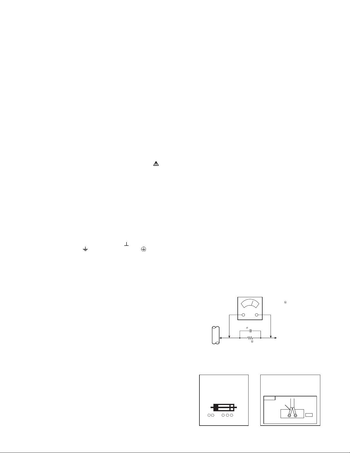
Alternate Check Method
Plug the AC line cord directly into the AC outlet (do not use a
line isolation transformer during this check.). Use an AC
voltmeter having 1000
following manner. Connect a 1500
a 0.15
µF AC-type capacitor between an exposed metal part
Ω per volt or more sensitivity in the
Ω 10W resistor paralleled by
and a known good earth ground (water pipe, etc.). Measure the
AC voltage across the resistor with the AC voltmeter. Move the
resistor connection to each exposed metal part, particularly any
exposed metal part having a return path to the chassis, and
measure the AC voltage across the resistor. Now, reverse the
plug in the AC outlet and repeat each measurement. Any
voltage measured must not exceed 0.75V AC (r.m.s.). This
corresponds to 0.5mA AC (r.m.s.).
However, in tropical area, this must not exceed 0.3V AC
(r.m.s.). This corresponds to 0.2mA AC (r.m.s.).
AC VOLTMETER
(HAVING 1000 /V,
OR MORE SENSITIVITY)
0.15 F AC-TYPE
PLACE THIS PROBE
1500 10W
(11) High voltage hold down circuit check.
GOOD EARTH GROUND
ON EACH EXPOSED
ME TAL PAR T
After repair of the high voltage hold down circuit, this circuit shall
be checked to operate correctly.See item "How to check the high
voltage hold down circuit".
This mark shows a fast
operating fuse, the
letters indicated below
show the rating.
A V
POWER CORD
REPLACEMENT WARNING.
Connecting the white line side of power
cord to "WHT" character side.
PWB
White line side
WHT
PW
(No.52163)1-3
Page 4
1.2 INSTALLATION
1.2.1 REMOVING THE UPPER UNIT FROM THE LOWER UNIT
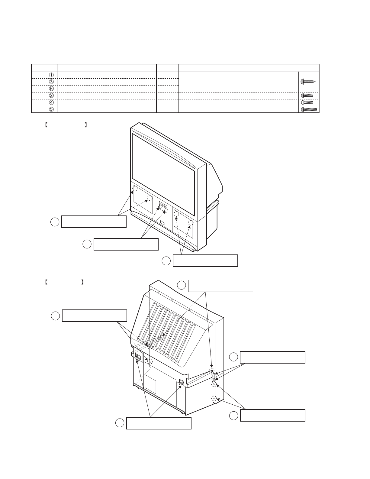
1.2.1.1 TYPES AND PLACES OF SCREWS
• Be careful not to confuse the following four types of screws.
Type
Ref. Place for attaching screws Quantity Color Shape
A
A
A
B
C
D
Front panel bracket
Rear cover bracket
Rear cover (for attaching the body)
Inside the Front door (in the jack part)
Rear cover (for attaching the body bracket)
Rear cover (for attaching the speaker panel)
4
2
2
2
2
4
FRONT SIDE
Black
Black
Gold
Black
diameter of 4mm-length of 18mm, acute tip
diameter of 3mm-length of 12mm, flat tip
diameter of 4mm-length of 12mm, flat tip
diameter of 4mm-length of 20mm, flat tip
A : diameter of 4mm - length
1
of 18mm, black, acute tip
2
REAR SIDE
D : diameter of 4mm - length
5
of 20mm, black, flat tip
B : diameter of 3mm - length
of 12mm, black, flat tip
A : diameter of 4mm - length
1
of 18mm, black, acute tip
C : diameter of 4mm - length
4
of 12mm, gold, flat tip
A : diameter of 4mm - length
3
of 18mm, black, acute tip
1-4 (No.52163)
A : diameter of 4mm - length
6
of 18mm, black, acute tip
D : diameter of 4mm - length
5
of 20mm, black, flat tip
Page 5
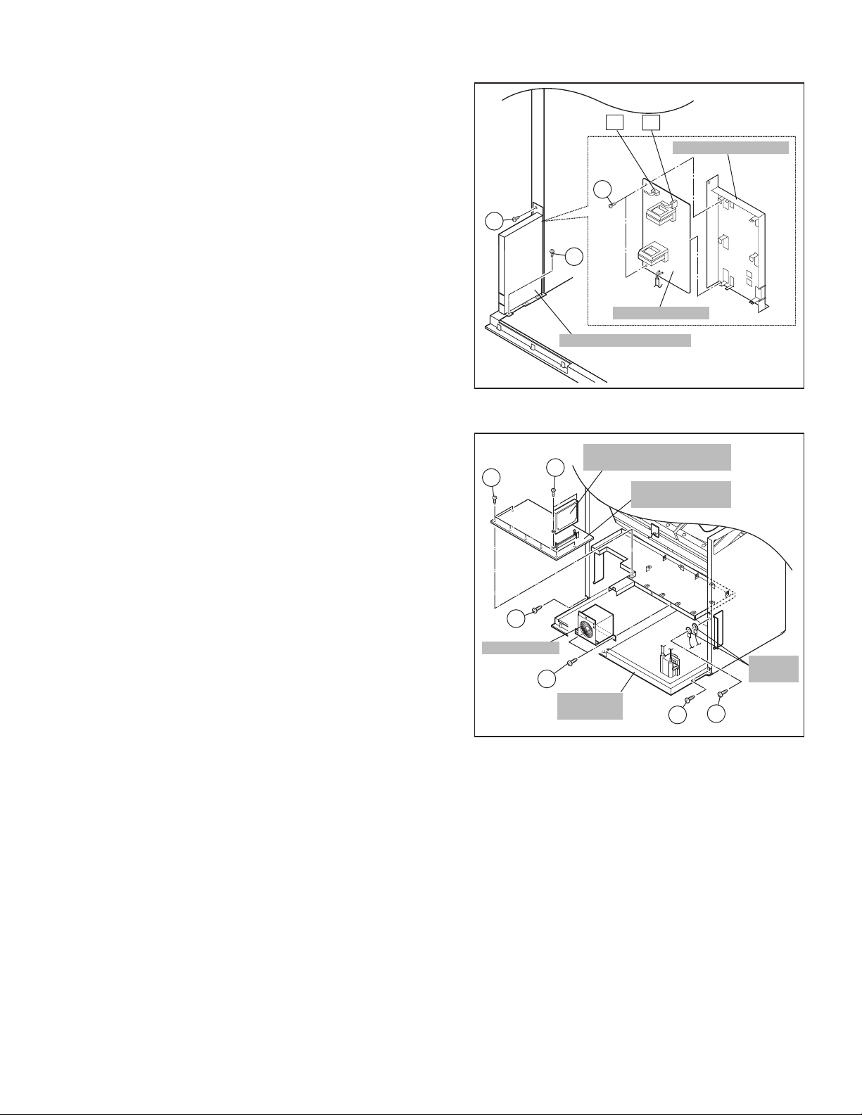
1.2.1.2 DISASSEMBLY PROCEDURE
• Make sure that the power cord is pulled out from the AC wall
socket.
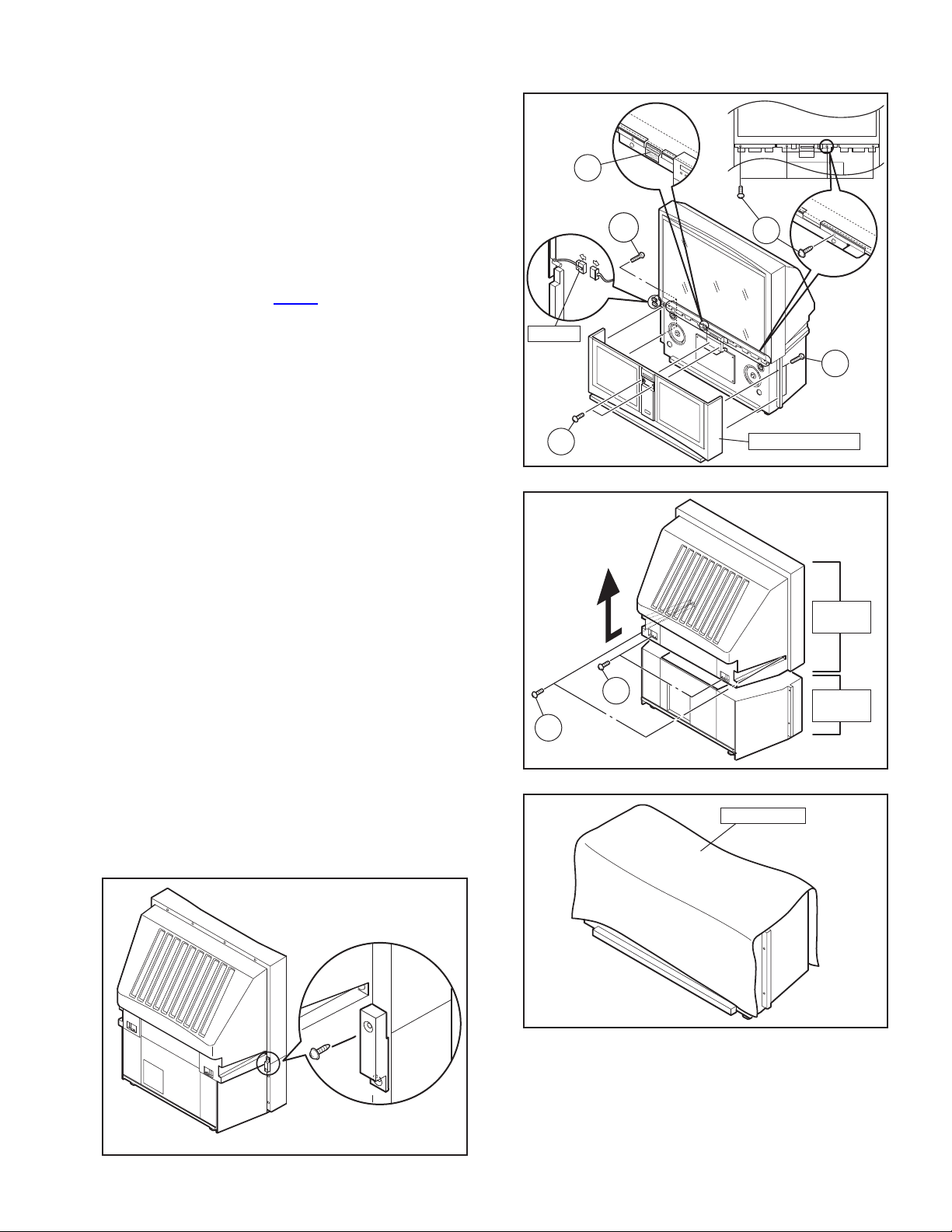
(1) Remove the 2 screws [ A ] on the left rear sid e of the set,
and then remove the rear cover bracket. [Fig.1]
(2) Remove the 2 screws [ B ] inside of the front door. [Fig.2]
* The screws attach the speaker grill.
(3) Remove the 2 screws [ D ] on the left edge of the rear
cover, and remove the 2 screws [ D ] on the right edge of
the rear cover. [Fig.2]
* The screws attach the speaker grill.
(4) Pull the speaker grill in front direction, and remove the
speaker grill. [Fig.2]
(5) Remove the connector [CN00Z
sensor on the left side of the set, and the clamp fixing the
wire. [Fig.2]
(6) Remove the 2 screws [ A ] on the left front panel bracket,
and remove the 2 screws [ A ] on the right front panel
bracket. [Fig.2]
(7) Remove 1 screw C on th e left edge of the rear cover, a nd
1 screw C on the right edge of the rear cover. [Fig.3]
(8) Remove 1 screw [ A ] on the left side of the rear cover, and
remove 1 screw [ A ] on the right side of the rear cover.
[Fig.3]
(9) Move the rear cover approx. 3cm in rear direction. Then,
remove the upper unit from the lower unit by lifting the
upper unit slowly. [Fig.3]
•VOID seal [ a ] attached to the left front panel bracket in
order to confirm that a person except JVC installation
workers has disassembled the set. This seal is removed
when the upper unit is removed, and the letters of "VOID"
appears in the place where the seal. [Fig.2]
• Two or more people are required to move the upper unit.
• Reflecting mirror is attached to the upper unit. So, handle
it carefully so as to protect it from shocks.
• In placing the upper unit on the ground, be careful not to
insert the connector for the auto-convergence on the
right side of the upper unit between the upper unit and
the ground.
• In placing the upper unit on the ground, be careful not to
insert dust inside the upper unit.
• Be careful not to hurt yourself because metal brackets for
attaching the front panel are on the ceiling part of the
lower unit.
(10) Cover the lower unit with the Top Sheet in order not to
insert dust in the lower unit. Top Sheet is the one used for
package. [Fig.4]
] for the auto-convergence
CN00Z
B
C
a
D
A
D
SPEAKER GRILL
Fig.2
UPPER
UNIT
A
Fig.3
TOP SHEET
LOWER
UNIT
Fig.1
Fig.4
(No.52163)1-5
Page 6
1.2.1.3 REASSEMBLY PROCEDURE
• Make sure that power cord is pulled out from the AC wall
socket.
• Remove the Top Sheet which covers the lower unit.
(1) Lift the upper unit slowly, and then place the upper unit on
the lower unit.
• In placing the upper unit on the lower unit, be careful not
to insert the connector for the auto-convergence on the
left side of the upper unit between the upper unit and the
lower unit.
(2) Adjust the front side of the upper unit to the brackets on the
lower unit for attaching the upper unit.
(3) Attach 2 screws [ A ] to the both side of the rear cover.
[Fig.2]
(4) Attach 2 screws [ A ] to the both edg e of the rear cover.
[Fig.2]
(5) Attach the 4 screws [ A ] to the front panel bracket. [Fig.2]
(6) Attach the VOID seal [ b ] on the front right side of the set
to the right front panel bracket. [Fig.5]
(7) Attach the speaker grill to the front side.
(8) Attach 4 screws [ D ] to the both edg e of the rear cover.
[Fig.2]
(9) Attach the 2 screws [ B ] to the front door. [Fig.2]
(10) Attach the connector for the auto-convergence sensor.
• Make sure that all the screws are attached certainly in
order to fix the upper unit.
• After assembly procedure is completed, make sure that
there is no dust in the inner side of the screen.
b
Fig.5
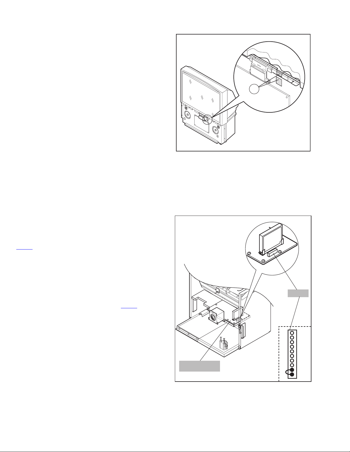
1.2.1.4 SPLIT PROTECTION
A protection circuit, which stops the power supply to the upper
and lower parts of the unit, is added from this set.
Thanks to the protection circuit, the power supply is turned off
automatically when you try to turn the power on while the unit is
broken out into the upper and lower parts and the connector
is disconnected.
CN00Z
When the power is turned off by the protection circuit, POWER
LED will flash on and off at intervals of three seconds. This is
counted at SPRT of the self-diagnostic mode.
Because of this protection circuit, you cannot turn the power on
when you try to check the functions and the signal waveform of
the unit during servicing. It is necessary to invalidate the
functions of protection circuit for turning the power on.
Method to invalidate the functions of protection circuit
Cause short circuit the pins 9 and 10 of the CN00Z
connector
on the CONVERGENSE OUT PWB ASS'Y.
CONVERGENCE
OUT PWB
CN00Z
1
2
3
4
5
6
7
8
9
10pin
1-6 (No.52163)
Page 7
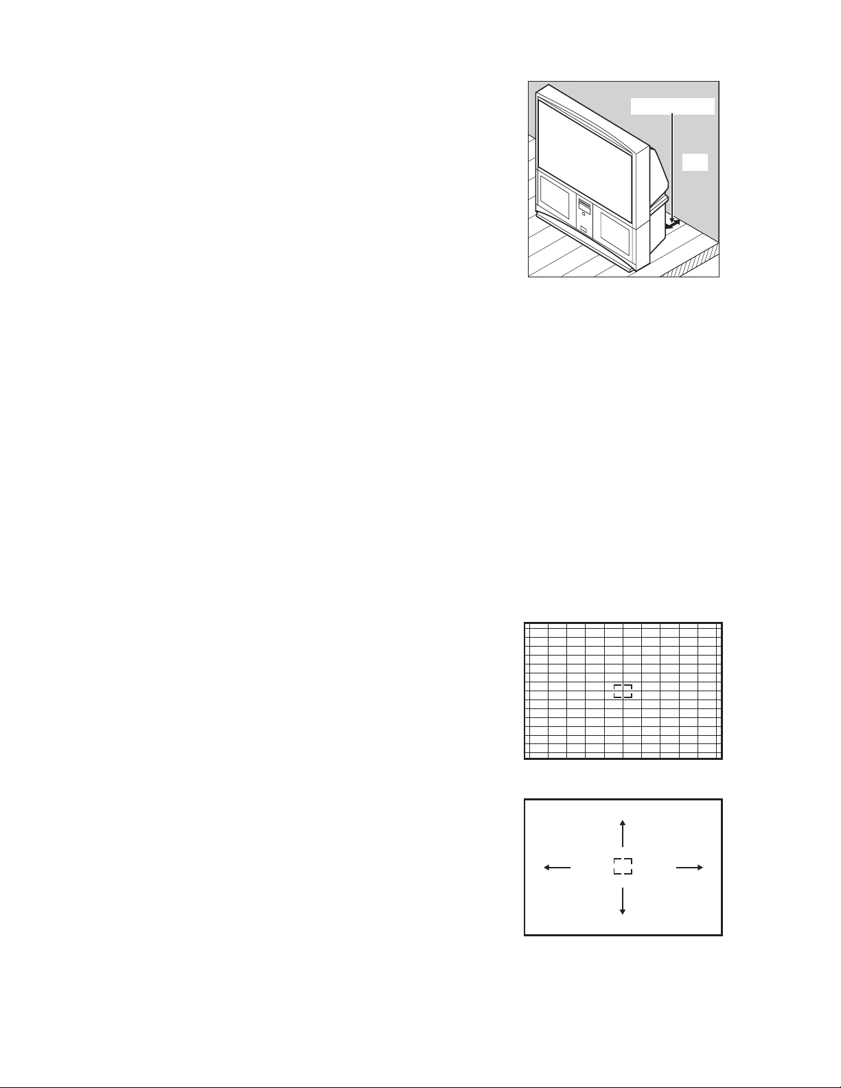
1.2.2 INSTALLATION SITE
(1) The rear of this set is provided with ventilation ope nings.
Install the set more than 5 cm from a wall and in a location
with good ventilation.
(2) Avoid the following types of locations.
a) Unstable locations (location must be able to
withstand heavy weight).
b) Locations subjected to direct sunlight.
c) Near stoves or other heating devices.
d) Locations subjected to humidity or oily smoke.
e) Dusty locations.
f) Locations with strong vibration.
1.2.3 INSTALLATION ADJUSTMENT
When installing, moving or changing the o rientation of the set,
perform static convergence adjustment according to the
following procedure.
Adjusting CRT color convergence have two method, AUTO,
MANUAL and RESET. It adjust on the MENU screen.
NOTE :
Please have you TV on for at least 20 minutes before sing this
feature.
This adjustment will be needed only when the colors of the
characters/lines are separated and lack in distinction. If not,
please don't perform the adjustment.
AUTO
(1) Press the [MENU] key, and select the
"CONVERGENCE" in the INITIAL SETUP menu with
[function up/down] key.
(2) Press the [function left/right] key, then CONVERGENCE
menu appear.
(3) Press the [function up/down] key, and select the
"AUTO".
(4) Press the [function left/right] key.
(5) The convergence adjustment will start. It will take about
50 seconds.
MANUAL
(1) Press the [MENU] key, and select the
"CONVERGENCE" in the INITIAL SETUP menu with
[function up/down] key.
(2) Press the [function le ft/right] key, the CONVERGENCE
menu appears.
(3) Press the [function up/down] key, and select the
"MANUAL".
(4) Press the [function left/right] key, then CONVERGENCE
adjustment screen appear. [Fig.1]
• If all the crosses are white, no convergence
adjustment is needed.
(5) Select the location you want to adjust by using the
[number (2/4/5/6/8)] keys on the remote control unit.
[Fig.2]
(6) Press the [SELECT] key to change the color of the box
to the color of the cross you want to adjust (red or blue).
• You cannot adjust the green cross.
(7) Use the [function up/down] key and the [function left/
right] keys to adjust the position of the cross.
(8) Adjust the three colors crosses until they overlap and
appear as a single white cross.
(9) Press the [OK] key.
(more than 5cm)
Wall
VENTILATION OPENING
NOTE :
• When you adjust the convergence, make sure you
start with the center position (position 5), and work
your way around radial for best results.
• When you make the adjustment in the center
(positions 5), you are making the adjustment for the
whale screen. In other positions, you are making the
adjustment only in that area.
• You can reset the adjustment if you do not like the
results, See below.
• If you perform AUTO CONVERGENCE after
performing MANUAL CONVERGENCE, your
manual convergence you performed will be
cancelled.
(10) Press the [menu] key to end the convergence
adjustment procedure.
RESET
RESET in the CONVERGENCE menu resets all convergence
adjustments to the factory default setting.
Fig.1
2
46
5
8
Fig.2
(No.52163)1-7
Page 8
SECTION 2
/ MONO
SPECIFIC SERVICE INSTRUCTIONS
2.1 FEATURES
• New chassis design enable use of an interactive on screen control.
• 2-3 PULL DOWN : You can enjoy DVD movies at the highest picture quality.
• MOTION COMPENSATION : With this function, the seamless reproduction of dynamic motion on the screen has been realized.
• Bullet-in DSD (Digital Supper Detail) circuit and 3 dimension Y/C separate circuit.
• Receive DTV broadcast (1080i / 720p / 480p / 480i)
• Built-in HDCP / Component (Y / Pb / Pr) input.
• Built-in Hyper Sound, BBE circuit.
• D.I.S.T. 1500i : D.I.S.T. 1500i is the function to change a input visual signal into the high definition 1500 inte rlace signal.
2.2 FUNCTIONS
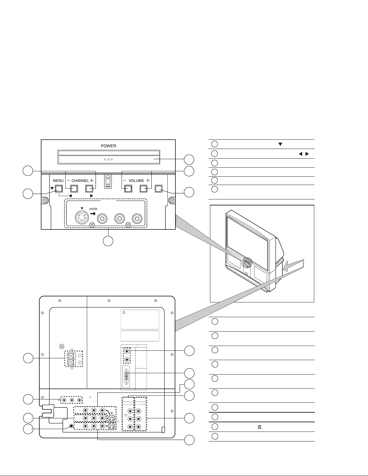
FRONT CONTROL KEY & TERMINAL
1
MENU button ( OPERATE )
2
5
2
SUPER
FOCUS
1
OPERATE
S-VIDEO
INPUT-4
VIDEO AUDIO
L / MONO
R
3
4
CHANNERL -/+ buttons ( OPERATE / )
3
VOLUME -/+ buttons
4
SUPER FOCUS button
5
MAIN POWER button
6
INPUT4
( AUDIO / VIDEO / S-VIDEO )
REAR TERMINAL
( VHF/UHF )
7
SUBWOOFER
OUT
8
3
9
75
SPEAKER INPUT
16 60W MAX
AUDIO OUT
AV COMPULINK III
R L
INPUT 3
INPUT 2
INPUT 1
AUDIO
R L
6
VIDEO S-VIDEO
OVER
OVER
UNPLUG THE POWER CORD FROM AC OUTLET
BEFORE REMOVING THE REAR COVER
When the rear cover is removed, follow "CAUTION AT DISASSEMBLY"
procedure in the service manual before plugging the TV’s power
cord into an AC outlet. Failure to follow the procedure will result
in PERMANENT damage to some of the television features.
DBRANCHEZ LE CORDON DE LA PRISE DE COURANT
C. A. AVANT DE RETIRER LE COUVERCLE ARRI¨RE.
Une fois le couvercle arriŁre dØposØ suivez l procØdure
« ATTENTION LORS DU DMONTAGE » dØcrite dans une
prise c.a. L’omission de suivre la procØdure causera des
dommages PERMANENTS certaines fonctions du tØlØviseur.
Licensed from BBE Sound, Inc. under USP4638258, 4482866
and 5510752.
BBE is a registered trademark of BBE Sound, Inc.
Sous licence de BBE Sound, Inc.
BBE est une marque de fabrique dØposØe de BBE Sound, Inc.
Autorizado con licencia de BBE Sound, Inc.
BBE es une marca comercial registrada de BBE Sound, Inc.
DIGITAL IN
R
AUDIO
L
VIDEO
COMPONENT VIDEO
INPUT 1INPUT 2
Y
b
P
Pr
Y
b
P
Pr
10
1
4
6
5
2
1
DIGITAL IN
( DVI signal link 24pin )
2
INPUT 1
( AUDIO / VIDEO / S-VIDEO )
3
INPUT 2
( AUDIO / VIDEO )
4
INPUT 3
( AUDIO / VIDEO / S-VIDEO )
5
COMPONENT VIDEO INPUT 1
( Y / Pb / Pr )
6
COMPONENT VIDEO INPUT 2
( Y / Pb / Pr )
7
SPEAKER INPUT
8
SUBWOOFER / AUDIO OUT
9
AV COMPULINK
10
AUDIO INPUT (For DIGITAL IN)
1-8 (No.52163)
Page 9
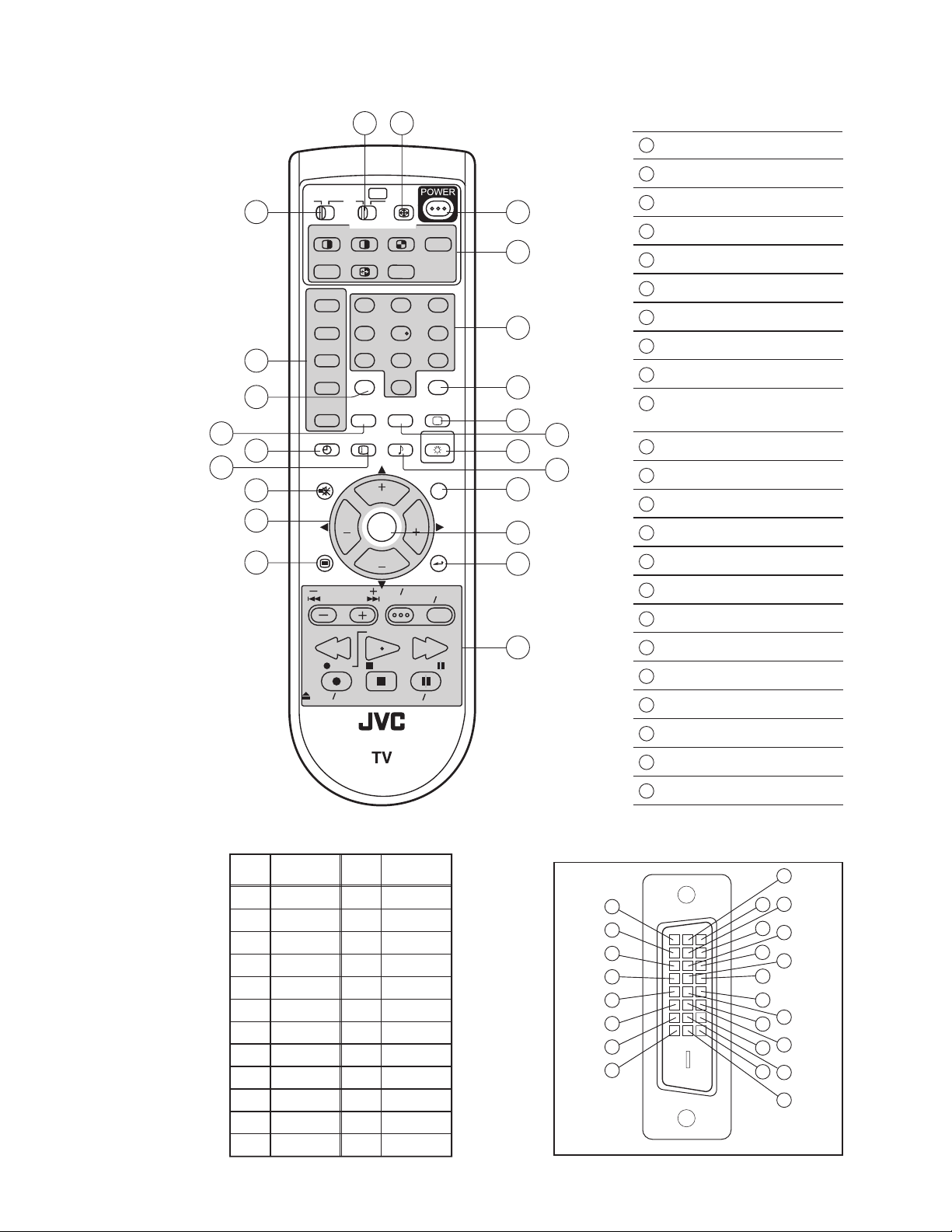
REMOTE CONTROL UNIT [RM-C11G]
TV
CATV VCR DVD
MULTI SCREEN
SPLIT POP
FREEZE
SWAP SELECT
INPUT 1
V1
INPUT 2
5
14
6
INPUT 3
INPUT 4
DIGITAL-IN
SLEEP TIMER
7
8
MUTING
9
10
11
MENU
OPEN CLOSE
123
V2
456
V3
789
100+
V4
THEATER
PRO
D-IN
DISPLAY SOUND
+
VOL VOL
VCR CHANNEL
PREV NEXT
REW
REC PAUSE
ASPECT
INDEX
NATURAL
CINEMA
CH
OK
CH
VCR DVD
POWER
STOP
23
EZ SURF
RETURN+
0
VIDEO
STATUS
LIGHT
C.C.
BACK
TV VCR
FFPLAY
STILL PAUSE
1
POWER key
2
ASPECT key
3
14
12
13
TV
15
16
17
18
19
C.C.
20
21
22
23
VCR / DVD Switch
4
TV / CATV Switch
5
Input select keys
6
THEATER PRO key
7
SLEEP TIMER key
8
DISPLAY key
9
MUTING key (memory key)
10
CH + / CH - / VOL + / VOL - keys
(Function up / down / right / left keys)
11
MENU key
12
MULTI SCREEN operation keys
13
Number (1~0) keys
14
100+ key
15
RETURN+ / TV key
16
VIDEO STATUS key
17
NATURAL CINEMA key
18
LIGHT key
19
SOUND key
20
C.C.(Closed Caption) key
DIGITAL-IN TERMINAL FUNCTIONS
Pin
Pin name
No.
1 RX2-
2 RX2+
3 GND2/ 4
4 RX4-
5 RX4+
6 SCL
7 SDA
8NC
9 RX1-
10 RX1+
11 GND1/3
12 RX3-
Pin
No.
13 RX3+
14 5V
15 GND
16 HTPLG
17 RX0-
18
19 GND0/5
20 RX5-
21 RX5+
22 GNDC
23 TXC+
24 TXC-
RM-C11G
Pin name
RX0+
PIN ASSIGNMENT
17
18
19
20
21
22
23
24
21
OK key
22
BACK key
23
VCR / DVD operation keys
9
10
1
2
11
3
12
4
5
13
6
14
7
8
15
16
(No.52163)1-9
Page 10
2.3 TECHNICAL INFORMATION
2.3.1 MAIN MICRO COMPUTER (CPU) FUNCTION (MN102H75K)
Pin No. Pin name I/O Function
1 CONV.SW O -------2 /MICON_V I V.sync for OSD
3 LB_PRO I Low B protection detection
4 NC - -------5 /RST I Main CPU reset [Reset:L]
6 NC - -------7 /TEST I +3.3V
8 OSD_YS O OSD Ys output
9 NC - -------10 NC - -------11 A_MU O Audio muting [Muting:H]
12 /MICON_H I H sync for OSD
13 M_MU O -------14 P46,OSDXI - -------15 P45,OSDXO - --------
2
16 SDA2 I/O I
C bus (CLK) for MTS
17 AC_IN I AC (60Hz) input
2
18 SCL2 O I
C bus (DATA) for MTS
19 TU_POW O Tuner power control
20 VCOI I LPF input
21 PDO O LPF output
22 /IP_RESET O Reset
23 OSD_YM O OSD Ym output
24 OSD_B O OSD blue output
25 POWER_LED O Lighting for POWER LED
26 OSD_G O OSD green output
27 OSD_R O OSD red output
28 VREF I Reference voltage for OSD
29 IP_ERR I AMDP program load detect.
30 IREF I Reference current for OSD
31 COMP I Phase adjust for OSD
32 AVDD I +3.3V
33 CLL I Closed caption decoder for SUB
34 VREFLS I Standard voltage input for SUB
35 SUB_CCD I Closed caption decoder for SUB
36 NC - -------37 VSS I GND
38 MAIN_CCD I Closed caption decorder for MAIN
39 VREFHS I Standard voltage input for MAIN
40 CLH I For sub CCD
41 VDD/VPP I +3.3V
42 CLK SW1 O IP clock switch
Pin No. Pin name I/O Function
43 CLK SW2 O IP clock switch
44 ON_TIM O Lighting for on timer operating
45 SBO 0 O Convergence control
46 SBD 0 I Convergence control
47 SBT1 I -------48 AP_DATA - -------49 BS_RST - -------50 SQR - -------51 BS1.5CTL - -------52 ABL/ACL O ABL/ACL control
53 CHROMA O Chroma/Gamma control
54 DC_COTL O Black level DC reproduce control
55 BS_POW - -------56 I2C_STOP - -------57 TU2_AID I Main AFT voltage
58 /LOB_POW O LowB power control [Power on:L]
59 COMPULINK I AV COMPULIN III control
60 /POWERGOOD I Power condition check
61 MECA_ON I Machine SW interrupt [Pushing:L]
62 /MAIN_POW O Main power control [Power on :L]
63 NC - -------64 /B1 POW O B1 power control [Power on:L]
65 C/N - -------66 X_RAY I X-ray protection detection
[Protect 0.7V]
67 NC - -------68 KEY2 I Front key input 2 (CH+ Vol-/+)
69 KEY1 I Front key input 1 (Menu CH-)
2
70 SCL1 O I
71 SDA1 I/O I
C bus (CLK) for EEP-ROM
2
C bus (SDA) for EEP-ROM
72 REMO I Remote control input
73 AP_REQ - -------74 VSS I GND
75 OSC2 O 4MHz oscillation for system clock
76 OSC1 I 4MHz oscillation for system clock
77 VDD I +3.3V
2
78 SCL0 O I
C bus (CLK) for general
79 AP_CLK - --------
2
80 SDA0 I/O I
C bus (SDA) for general
81 NC - -------82 BS_TXD - -------83 NC - -------84 P_MU O Picture muting
1-10 (No.52163)
Page 11
2.4 MAIN PARTS LOCATION
2.4.1 PWB ASS'Y ARRANGEMENT
The PWB ASS'Y is indicated below.
• MAIN PWB ASS'Y (SSB-1077A-M2)
• RECEIVER PWB ASS'Y (SSB0R377A-M2)
• MI-COM & DIST MODULE PWB ASS'Y (SSB0D077A-M2)
• POWER & DEF PWB ASS'Y (SSB-2077A-M2)
• DEF OSC PWB ASS'Y (SSB0H077A-M2)
• LINE FILTER PWB ASS'Y (SSB-9077A-M2)
• FRONT RELAY PWB ASS'Y (SSB0L268A-M2)
• CONVERGENCE OUT PWB ASS'Y (SSB-5077A-M2)
FRONT CONTROL ASS'Y
• DIGITAL CONVERGENCE MODULE PWB ASS'Y
(SSB0K077A-M2)
• DIGITAL INPUT MODULE PWB ASS'Y
• REMOCON SENSOR PWB ASS'Y (SSB-8068A-M2)
• R CRT SOCKET PWB ASS'Y (SSB-3177A-M2)
• G CRT SOCKET PWB ASS'Y (SSB-3277A-M2)
• B CRT SOCKET PWB ASS'Y (SSB-3377A-M2)
• G VM PWB ASS'Y (SSB-7277A-M2)
• FRONT CONTROL PWB ASS'Y (SSB0L077A-M2)
PROJECTION UNIT
FRONT CONTROL
PWB
FRONT RELAY
PWB
MI-COM & DIST
MODULE PWB
LINE FILTER
PWB
RECEIVER PWB
MAIN PWB
CRT SOCKET
PWB (R/G/B)VMPWB (G only)
REMOCON SENSOR
PWB
DIGITAL CONVERGENCE
MODULE PWB
POWER & DEF
PWB
DEF OSC
PWB
AV TERMANEL BOARD
(This figure is only MAIN UNIT)
CONVERGENCE OUT
PWB
DIGITAL INPUT
MODULE PWB
(No.52163)1-11
Page 12
2.5 SCREEN HANDLING CAUTIONS
2.5.1 SCREEN STOR AGE
Store the SCREEN ASS'Y in a standing position in order to avoid deformation. If the screen is stored horizontally, there is risk of
deforming the screen face.
When necessary to place the SCREEN ASS'Y horizontally, position the screen side upwards and sure to place spacers between the
screen and resting site (floor or stand etc.) to prevent the screen from sagging.
2.5.2 SCREEN SURFAC E
Since the screen surface is easily scratched or soiled, use ample care when handling.
DISASSEMBLY PROCEDURE
FRONT CABINET
If the screen or screen panel need to
be replaced, remove the 24 screws A.
SCREEN BRACKET
(TOP)
SCREEN BRACKET
(RIGHT)
SENSOR
SENSOR
A( x 7)
Leave the screen with protector fresnel
lens and double lenticular lens attached.
If cannot be disassembled further.
SCREEN
SENSOR
SCREEN BRACKET
(LEFT)
A( x 5)
A( x 7)
A( x 5)
SENSOR
SCREEN BRACKET
(BOTTOM)
2.6 PROJECTION UNIT REPLACEMENT
2.6.1 ADJUSTMENT DURING REPLACEMENT
When replacing the three R, G and B projection units, first replace the R and B units and perform focus / scre en / raster centering
adjustments with reference to the G unit. Then replace the G unit and pe rform G focus / screen / convergence adjustment. Finally
perform R & B . Convergence adjustments. Use care to simultaneously removes all three-projection units.
2.6.2 DISASSEMBLY CAUTION
The projection units include locations that are not to be disassembled during service. When replacing projection unit parts,
disassemble to the state indicated in the figure below.
The figure indicates screws and wires that are not to be removed. Use care not to remove these.
Deflection yoke wires : to connector on POWER & DEF. PWB ASS'Y.
[R="RHV", G="GHV", B="BHV"]
Convergence yoke wires : to connector on CONVERGENCE PWB ASS'Y.
[R="R", G="G", B="B"]
LENS ASS'Y SCREW ( x 4)
1-12 (No.52163)
Check that tape is applied to the CRT neck.
If absent, the deflection yoke can dislodge.
Do not remove screws
LENS ASS'Y
R CRT SOCKET PWB ASS'Y
G CRT SOCKET PWB ASS'Y
B CRT SOCKET PWB ASS'Y
PC MAGNET
PC MAGNET
TAP E
VM PWB (G only)
ANODE wires : to DIVIDER
DEF. / CONVER. YOKE
CRT ASS'Y (COUPLER ASS'Y)
Do not disassembly
Page 13
SECTION 3
DISASSEMBLY
3.1 DISASSEMBLY PROCEDURE
• Make sure that the power cord is pulled out from the AC wall
socket.
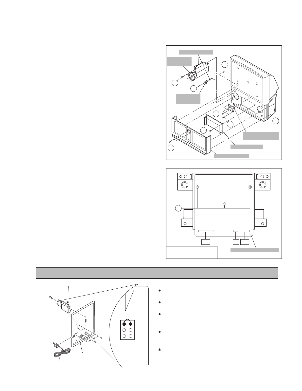
3.1.1 SPEAKER GRILLE
(1) Remove 4 screws [ A ] from rear side.
(2) Open the door of the FRONT CONTROL BOX and remove
2 screws [ B ] from front side.
(3) Take out the SPEAKER GRILLE.
3.1.2 SPEAKER (WOOFER)
• Take out the SPEAKER GRILLE.
(1) Remove 4 screws [ C ].
(2) Take out the WOOFER.
(3) Disconnect the speaker wire from speaker terminal.
*Remove the both side speaker same manner.
3.1.3 SPEAKER (TWEETER)
• Take out the SPEAKER GRILLE.
(1) Remove 2 screws [ D ].
(2) Take out the TWEETER.
(3) Disconnect the speaker wire from speaker terminal.
*Remove the both side speaker same manner.
3.1.4 FRONT BOARD
• Take out the SPEAKER GRILLE.
(1) Remove 4 screws [ E ].
(2) Take out the FRONT BOARD.
3.1.5 FRONT CONTROL BOX
• Take out the SPEAKER GRILLE.
(1) Remove 2 screws [ F ] and 2 screws [ G ] attaching the
FRONT CONTROL BOX.
(2) Disconnect the connector [BH], [R], [BG] on the FRONT
CONTROL PWB.
(3) Take out the FRONT CONTROL BOX.
3.1.6 FRONT CONTROL PWB
• Take out the SPEAKER GRILLE.
• Take out the FRONT CONTROL BOX.
(1) Remove 3 screws [ H ] from rear side of FRONT
CONTROL BOX.
(2) Take out the FRONT CONTROL PWB.
SPEAKER WIRE
SPEAKER
(WOOFER)
C
D
SPEAKER
(TWEETER)
E
B
H
BH BGR
FRONT CONTROL BOX
REAR SIDE
A
F
G
FRONT BOARD
SPEAKER GRILL
Fig.1
FRONT CONTROL PWB
Fig.2
A
FRONT CONTROL
BOX
CAUTION AT DISASSEMBLY
65WP84CP-S : DIGITAL INPUT MODULE
AV TERMINAL
POWER CORD
BOARD
1
3
5
SB
connector
Prior to disassembly, unplug the power code from the AC
outlet without fail. (Turn the power "off".)
Short the SB connector [1] pin and [2] pin of the DIGITAL
INPUT MODULE. (At the time of assembling)
Before the rear panel is inserted into the cabinet, release
2
4
6
the short-circuit between the SB connector [1] pin and [2]
pin of the DIGITAL INPUT MODULE.
After releasing the short-circuit between the SB
connectors, do not turn the power on until the rear panel
is inserted into the cabinet.
Negligence in carrying out the above steps may cause
the inactivation of the TV.
(No.52163)1-13
Page 14
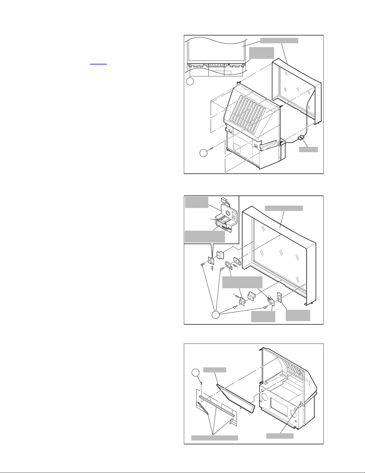
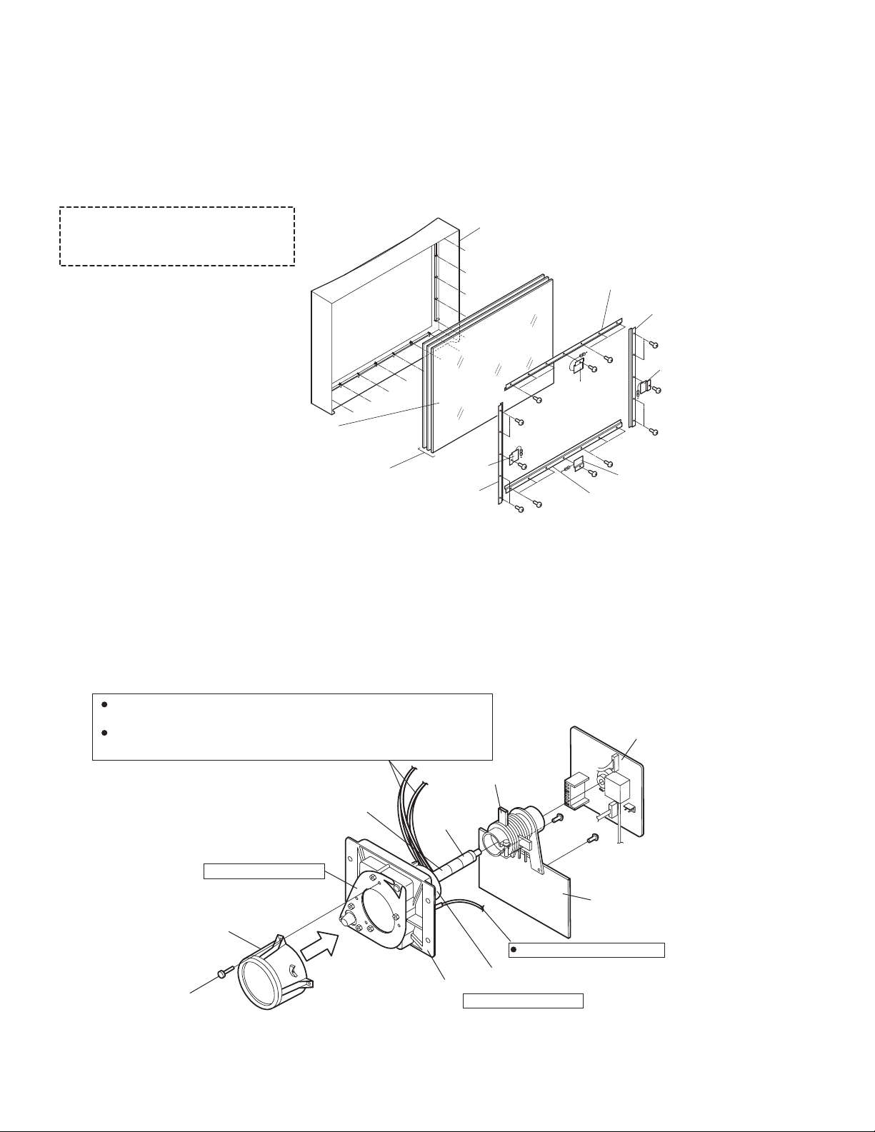
3.1.7 SCREEN ASS'Y
• Take out the SPEAKER GRILLE.
• Take out the FRONT CONTROL BOX.
(1) Remove the 4 screws [ I ] attaching the FRONT BRACKET.
(2) Remove 10 screws [ J ] from rear side.
(3) Take out the connector [ CN00Z
].
(4) Take out the SCREEN ASS'Y.
NOTE :
• Please place the SCREEN ASS'Y on a flat table without fail.
• Because of the large size, at least two parsons are
recommended for removal and reassemble.
• Use core not to scratch the screen during work.
• During assembly, be sure to engage the left and right tabs
with the cabinet mounting positions.
• When than sporting the SCREEN ASS'Y, avoid grasping the
top of the screen panel, instead grasp the left and right
areas.
SCREEN ASS'Y
FRONT
BRACKET
I
3.1.8 CONVERGENCE SENSOR
• Take out the SPEAKER GRILLE.
• Take out the FRONT CONTROL BOX.
(1) Remove the 4 screws [ K ] attaching the each SENSOR
HOLDER.
(2) Remove the claw of the SENSOR HOLDER to remove the
CONVERGENCE SENSOR.
3.1.9 MIRROR
• Take out the SPEAKER GRILLE.
• Take out the FRONT CONTROL BOX.
• Take out the SCREEN ASS'Y.
(1) Remove 10 screws [ L ] attaching the mirror brackets of the
upper, left and right side.
(2) Raise slightly to disengage of the mirror from th e bottom
bracket.(If necessary, loosen the screws attaching the
bottom bracket)
(3) Take out the MIRROR.
NOTE :
• The MIRROR is front-coated. Do not touch the front of
the MIRROR.
(4) At least 2 persons are recommended for removable and
reassemble.
J
SENSOR
HOLDER
CLAW
CONVERGENCE
SENSOR
K
MIRROR
L
MIRROR BRACKET
Fig.3
CONVERGENCE
SENSOR
SENSOR
HOLDER1
Fig.4
Fig.5
CN00Z
SCREEN ASS'Y
SENSOR
HOLDER2
BRACKET
1-14 (No.52163)
Page 15
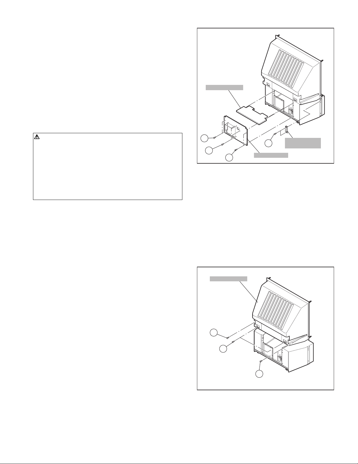
3.1.10 REAR PANEL
(1) Loosen 4 screws [ M ].
(2) Remove 4 screws [ N ].
(3) Raise slightly REAR PANEL upward.
(4) Take out the REAR PANEL.
NOTE :
• Before the rear panel is inserted into the cabinet, release the
short-circuit between the [SB] connector (1) pin and (2) pin
of the DIGITAL INPUT UNIT. (Refer to "CAUTION AT
DISASSEMBLY" on Page 14).
• After releasing the short-circuit between the [SB]
connectors, do not turn the power on until the rear pa nel is
inserted into the cabinet.
• Prior to starting the work, be sure to read the following
written instructions on the CAUTION LABEL attached to the
REAR PANEL.
PARTITION
Prior to starting the work, be sure to read the following
written instructions on the CAUTION LABEL attached to
the REAR PANEL.
UNPLUG THE POWER CORD FROM AC OUTLET BEFORE
OPEN THE REAR COVER (PANEL).
When the rear cover (panel) is removed, follow "CAUTION AT
DISASSEMBLY" procedure in the service manual before
plugging the TV's power cord into an AC outlet.
Failure to follow the procedure will result in PERMANENT
damage to some of the television features.
3.1.11 REAR COVER BRACKET
(1) Remove 2 screws [ O ].
(2) Take out the REAR COVER BRACKET.
3.1.12 PARTITION
• Take out the REAR PANEL.
(1) Pull out the PARTITION back ward.
3.1.13 REAR COVER
• Take out the SPEAKER GRILLE.
• Take out the FRONT CONTROL BOX.
• Take out the SCREEN ASS'Y.
(1) Remove 2 screws [ P ].
(2) Remove 2 screws [ Q ] from front side.
(3) Slightly pull for backside to disengage of the REAR
COVER from hooks.
(4) Take out the REAR COVER.
NOTE :
• Because of the large size, at least two persons are
recommended for removal and reassemble.
M
N
REAR COVER
Q
O
M
REAR PANEL
REAR COVER
BRACKET
Fig.6
P
Q
Fig.7
(No.52163)1-15
Page 16
3.1.14 MAIN UNIT
• Take out the SPEAKER GRILLE.
• Take out the connector [BH], [R], [BG] on the FRONT
CONTROL PWB.
• Take out the REAR PANEL.
(1) Remove 4 screws [ Q ] from front side.
(2) Remove 1 screw [ R ] attaching the MAIN CHASSIS and
BODY.
(3) Pull out the MAIN UNIT rear side.
NOTE :
• Except for confirmation of projection of images on the
screen and audio output through the speakers, the
removed MAIN UNIT is still workable in the same state
as if it is still built in the TV set. Therefore, the MAIN
UNIT can be removed, if necessary, for board
diagnosis, electric testing, etc. apart from confirmation
of screen images and audio output.
• When wire clamps are removed during work, use care
to restore them precisely to their original positions.
Performance can be affected if these are not returned
to the original positions.
• Because of the large size, at least two persons are
recommended for removal and reassemble.
• When carrying the MAIN UNIT, use care not to dr op,
shock or shake it.
• Do not stain or damage the lens of the PROJECTION
UNIT.
• Do not look through the PROJECTION UNIT.
3.1.14.1 CHECKING THE P.W. BOARD
When checking the MAIN PWB, POWER & DEF PWB, etc., raise
the MAIN UNIT with the HV DIVIDER side down for the sake of
convenience. You can checking the POWER & DEF PWB and
CONVERGENCE OUT PWB.
REAR SIDE
R
S
T
MAIN UNIT
BODY
Fig.8
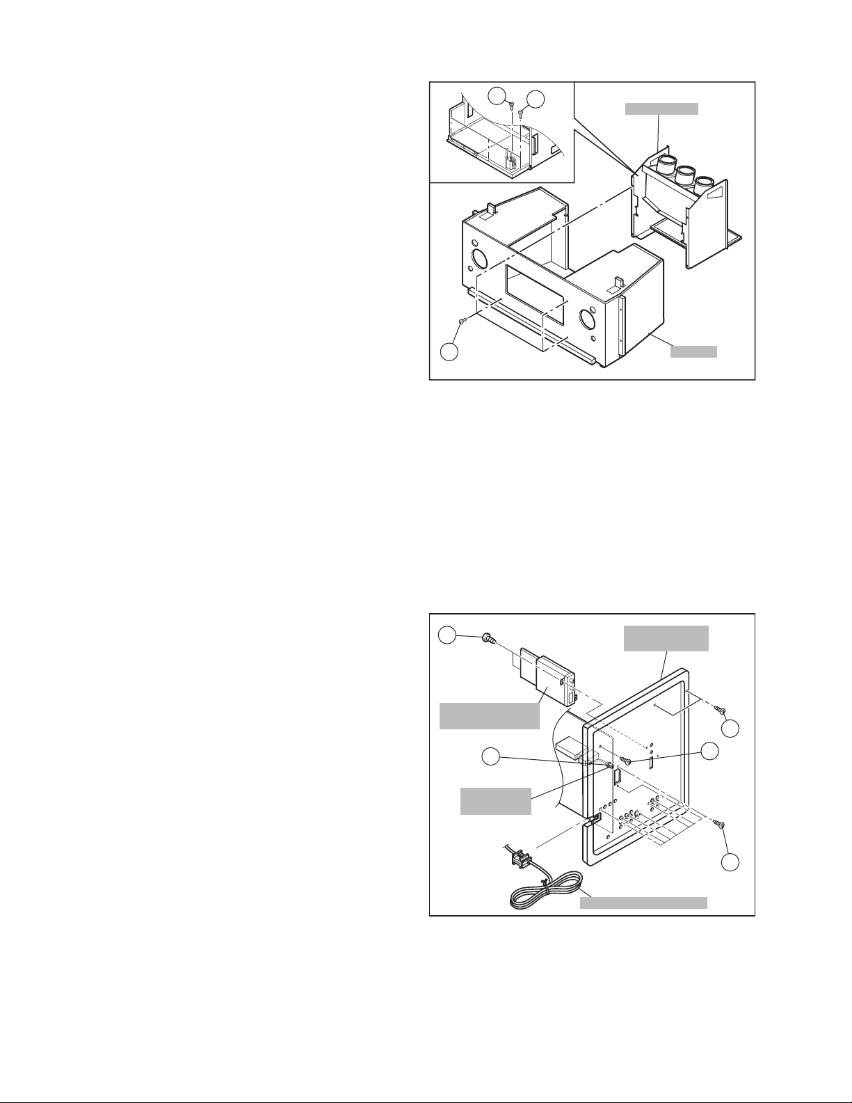
3.1.15 AV TERMINAL BOARD
• Take out the REAR PANEL.
(1) Remove 9 screws [ W ].
(2) Remove 1 screw [ X ].
(3) Remove 2 screws [ Y ].
(4) Pull out the POWER CORD CLAMP from AV TERMINAL
BOARD left side.
(5) Remove the nut [ Z ] attaching the ANTENNA TERMINAL.
(6) Take out the AV TERMINAL BOARD.
3.1.16 DIGITAL INPUT MODULE
• Take out the REAR PANEL.
(1) Remove 2 screws [ a ] from rear side of the AV TERMINAL
BOARD.
(2) Take out the DIGITAL INPUT MODULE.
NOTE :
• When removing the DIGITAL INPUT MODULE, refer
to the "CAUTION AT DISASSEMBLY" section on page
14.
a
DIGITAL INPUT
MODULE
Z
ANTENNA
TERMINAL
AV TERMINAL
BOARD
Y
X
W
POWER CORD CLAMP
Fig.9
1-16 (No.52163)
Page 17
3.1.17 LINE FILTER PWB
• Take out the REAR PANEL.
• Take out the AV JACK BOARD.
(1) Disconnect the connector [ B ], [ F ] on the LINE FILTER
PWB.
(2) Remove 3 screws [ U ] attaching the LINE FILTER
BRACKET and earth wire.
(3) Remove 2 screws [ V ] attaching LINE FILTER PWB.
(4) Take out the LINE FILTER PWB.
3.1.18 COOLING FAN
• Take out the REAR PANEL.
(1) Remove 2 screws [ b ].
(2) Take out the COOLING FAN.
3.1.19 CONVERGENCE OUT PWB AND DIGITAL
CONVERGENCE MODULE PWB
• Take out the REAR PANEL.
• Take out the AV TERMINAL BOARD.
(1) Remove 7 screws [ c ].
(2) Take out the CONVERGENCE OUT PWB and DIGITAL
CONVERGENCE MODULE PWB.
(3) Remove 2 screws [ d ].
(4) Take out the DIGITAL CONVERGENCE MODULE PWB.
NOTE :
• If necessary, remove the anode wires, connectors,
respectively.
3.1.20 MAIN CHASSIS
• Take out the REAR PANEL.
• Take out the AV TERMINAL BOARD.
• Take out the LINE FILTER BRACKET.
(1) Remove 2 screws [ e ] both side of the MAIN CHASSIS.
(2) Remove 1 screw [ f ] attaching the earth wire.
(3) Remove 3 screws [ T ] attaching the MAIN CHASSIS and
BODY. (See Fig. 8)
(4) Pull out the MAIN CHASSIS for back side.
NOTE :
• If necessary, remove the anode wires, connectors,
respectively.
U
c
e
COOLING FAN
b
BF
V
U
LINE FILTER PWB
LINE FILTER BRACKET
Fig.10
DIGITAL CONVERGENCE
d
MAIN
CHASSIS
MODULE PWB
CONVERGENCE
Fig.11
LINE FILTER BRACKET
OUT PWB
f
e
EARTH
WIRE
(No.52163)1-17
Page 18
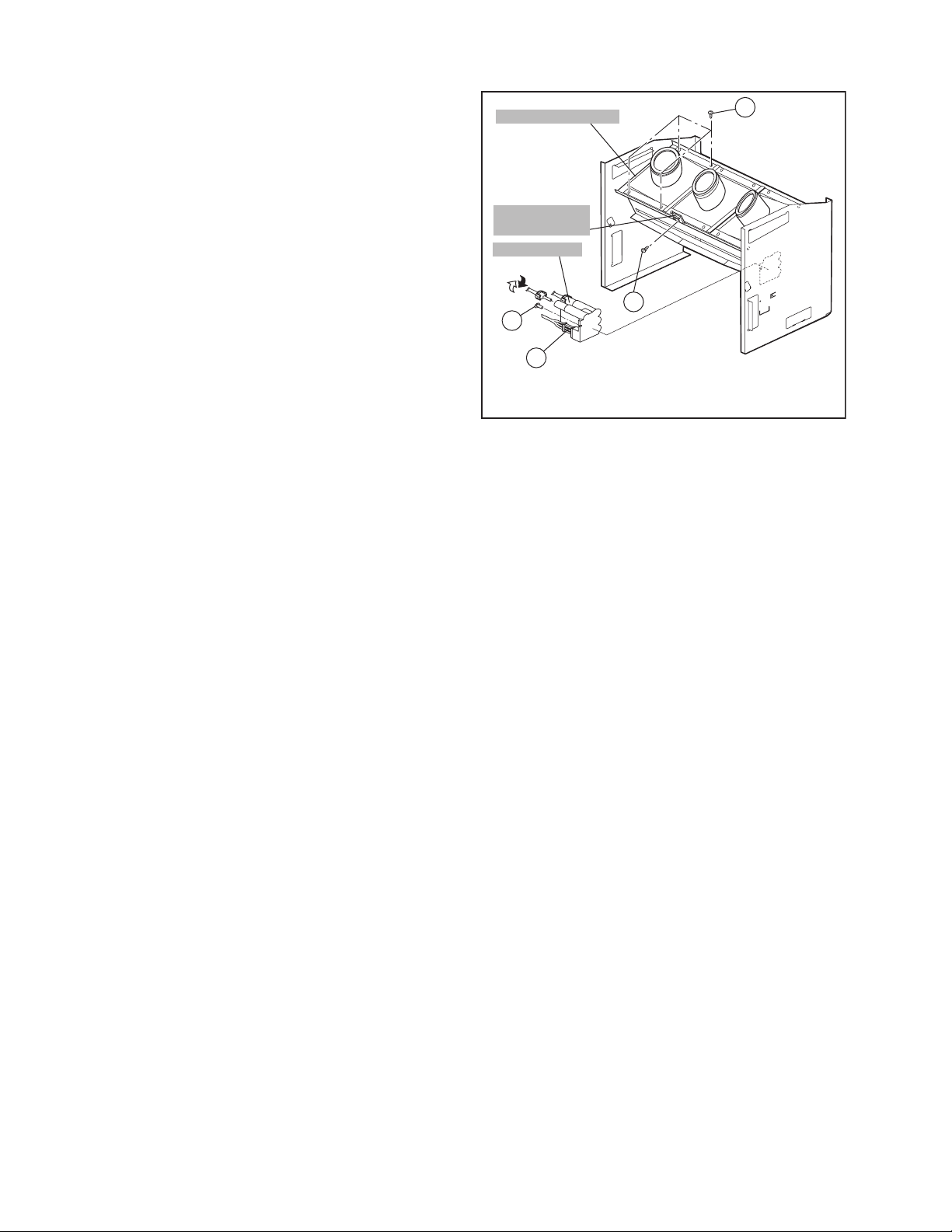
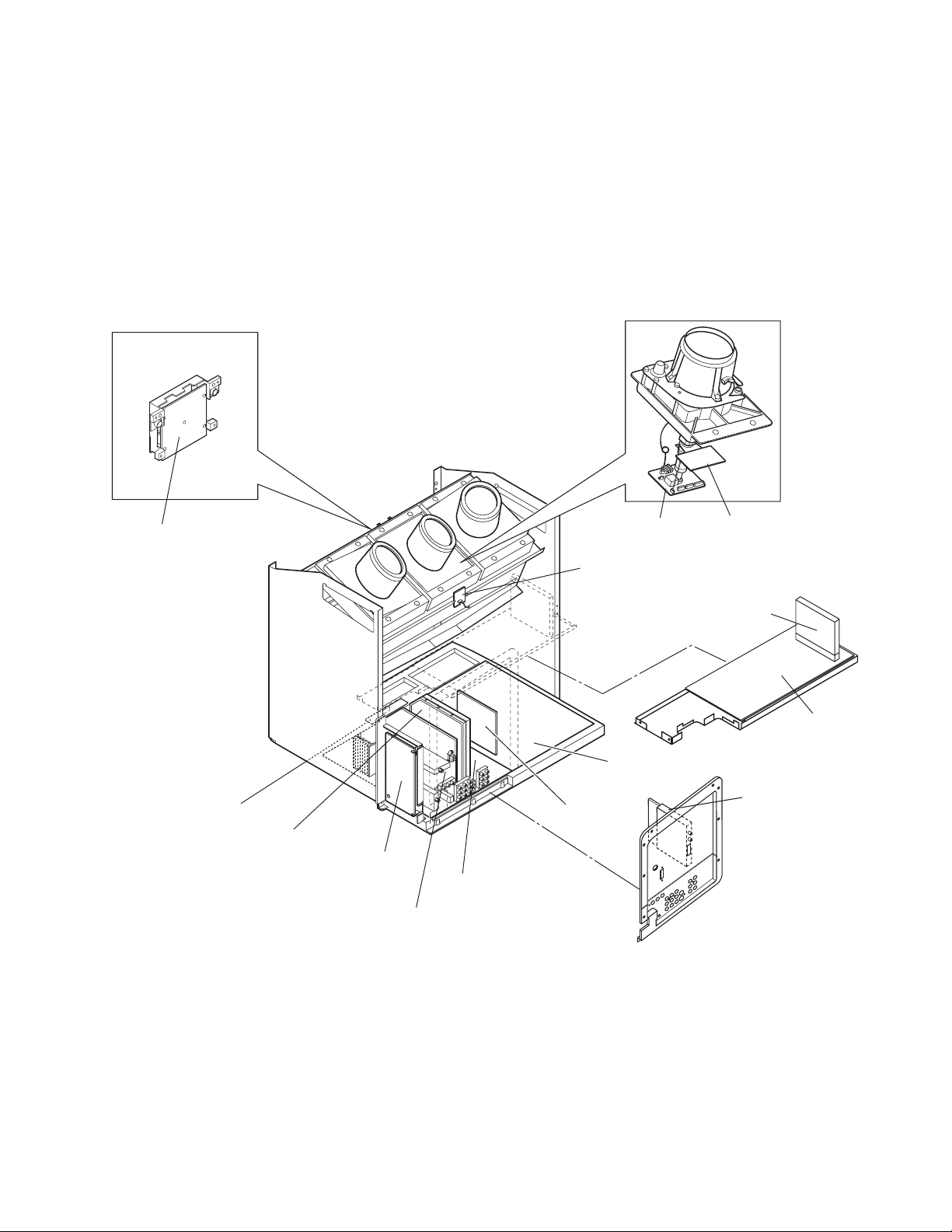
3.1.21 PROJECTION UNIT
• Take out the SPEAKER GRILLE.
• Take out the FRONT CONTROL BOX.
• Take out the REAR PANEL.
• Take out the MAIN UNIT.
(1) Take out the CRT SOCKET PWB.
(2) Remove 4 screws [ g ] attaching the PROJECTION UNIT.
(3) Pull out the PROJECTION UNIT, upward.
NOTE :
• Refer to "PROJECTION UNIT REPLACEMENT" on
page 13 when taking out and replacing the
PROJECTION UNIT.
• When wire clamps are removed during work, use care
to restore them precisely to their original positions.
Performance can be affected if these are not returned
to the original positions.
3.1.22 HV DIVIDER
• Take out the REAR PANEL.
(1) Remove 1 screw [ h ] attaching the HV DIVIDER.
(2) Take out the HV DIVIDER.
*Wires of the transformer (FBT) and CRT of each
PROJECTION UNIT can be removed by turning the
connector portions.
NOTE :
• If necessary, remove the anode wires, and replacing
the HV DIVIDER, take care to correctly engage the [ i ]
connector.
PROJECTION UNIT
REMOCON
SENSOR PWB
HV DIVIDER
Pull
Turn
h
i
g
j
Fig.12
3.1.23 REMOCON SENSOR PWB
• Take out the REAR PANEL.
(1) Remove 1 screw [ j ] attaching the REMOCON SENSOR
PWB.
(2) Take out the REMOCON SENSOR PWB.
1-18 (No.52163)
Page 19
3.2 REPLACEMENT OF CHIP COMPONENT
3.2.1 CAUTIONS
(1) Avoid heating for more than 3 seconds.
(2) Do not rub the electrodes and th e resist parts of the pattern.
(3) When removing a chip part, melt the solder adequately.
(4) Do not reuse a chip part after removing it.
3.2.2 SOLDERING IRON
(1) Use a high insulation soldering iron with a thin pointed end of it.
(2) A 30w soldering iron is recommended for easil y removing parts.
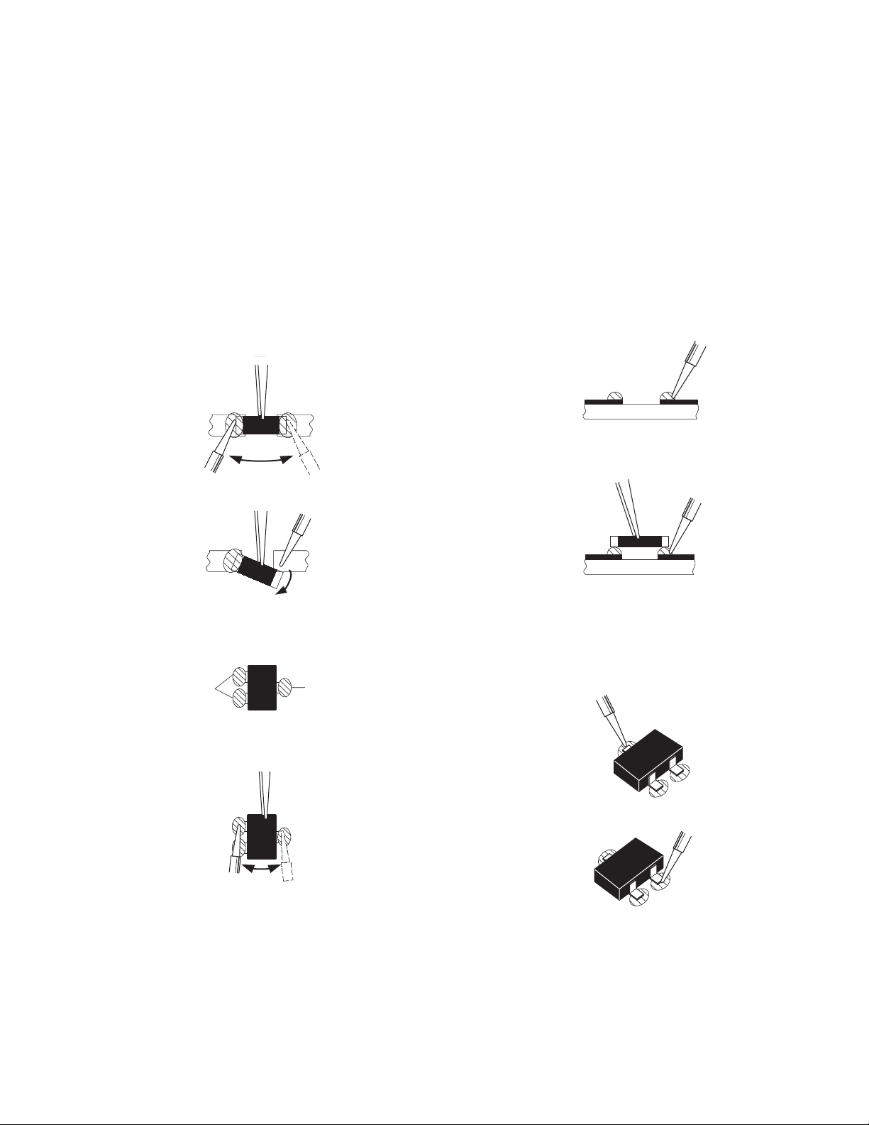
3.2.3 REPLACEMENT STEPS
1. How to remove Chip parts
2. How to install Chip parts
[Resistors, capacitors, etc.]
(1) As shown in the figure, push the part with tweezers and al-
ternately melt the solder at each end.
(2) Shift with the tweezers and remove the chip part.
[Transistors, diodes, variable resistors, etc.]
(1) Apply extra solder to each lead.
SOLDER
SOLDER
[Resistors, capacitors, etc.]
(1) Apply solder to the pattern as indicated in the figure.
(2) Grasp the chip part with tweezers and place it on the sol-
der. Then heat and melt the solder at both ends of the chip
part.
[Transistors, diodes, variable resistors, etc.]
(1) Apply solder to the pattern as indicated in the figure.
(2) Grasp the chip part with tweezers and place it on the sol-
der.
(3) First solder lead A as indicated in the figure.
(2) As shown in the figure, push the part with tweezers and al-
ternately melt the solder at each lead. Shift and remove the
chip part.
NOTE :
After removing the part, remove remaining solder from the pattern.
A
B
C
(4) Then solder leads B and C.
A
B
C
(No.52163)1-19
Page 20
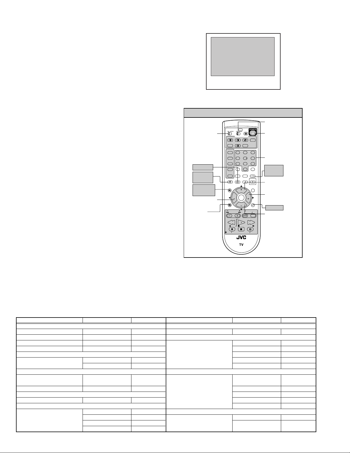
3.3 MEMORY IC REPLACEMENT
3.3.1 MEMORY IC
This memory IC stores data for proper operation of the video and
deflection circuits.
When replacing, be sure to use an IC containing this (initial
value) data.
SERVICE MENU
SERVICE MENU
1.PICTURE/SOUND
2.YC SEP
3.WHITE BALANCE
4.MEMORY SETUP
5.RF AFC
6.CONVER A
7.CONVER BD
8.PP
9.IP
0.HDMI
Fig.1
3.3.2 MEMORY IC REPLACEMENT PROCEDURE
(1) Power off
Switch off the power and disconnect the power cord from
the wall outlet.
(2) Replace the memory IC
Initial value must be entered into the new IC.
(3) Power on
Connect the power cord to the wall outlet and switch on the
power.
(4) SERVICE MENU setting
Before entering the SERVICE MENU, confirm that the setting
of TV/CATV SW of the REMOTE CONTROL UNIT is at the
"TV" side and the setting of VCR/DVD SW of the REMOTE
CONTROL UNIT is at the "VCR" side. If the switches have not
been properly set, you cannot enter the SERVICE MENU.
a) Press [SLEEP TIMER] key and, while the indication
of SLEEP TIMER 0 MIN is being displayed, press
[DISPLAY] key and [VIDEO STATUS] key on the
remote control unit (Fig.2) simultaneously.
b) The SERVICE MENU screen of Fig.1 is displayed.
c) Verify what to set in the SERVICE MENU, and set
whatever is necessary (Fig.1).
Refer to the SERVICE ADJUSTMENT for setting.
DISPLAY
SLEEP
TIMER
MEMORY
(MUTING)
FUNCTION
(LEFT)
MENU
SERVICE MENU SELECT KEY
TV
CATV VCR DVD
TV/CATV
switch
SLEEP TIMER
MULTI SCREEN
SPLIT POP
FREEZE
SWAP SELECT
INPUT 1
V1
123
INPUT 2
V2
456
INPUT 3
V3
789
INPUT 4
100+
V4
THEATER
DIGITAL-IN
PRO
D-IN
DISPLAY SOUND
+
MUTING
VOL VOL
MENU
VCR CHANNEL
PREV NEXT
REW
REC PAUSE
OPEN CLOSE
RM-C11G
CH
OK
CH
STOP
ASPECT
INDEX
0
NATURAL
CINEMA
VCR DVD
POWER
STILL PAUSE
EZ SURF
RETURN+
VIDEO
STATUS
LIGHT
C.C.
C.C.
BACK
TV VCR
FFPLAY
TV
VCR/DVD
switch
POWER
NUMBER
VIDEO
STATUS
FUNCTION
(UP)
FUNCTION
(RIGHT)
BACK
FUNCTION
(DOWN)
d) Press the [BACK] key twice to return normal screen.
(5) Receive channel setting
Refer to the OPERATING INSTRUCTIONS (USER'S
GUIDE) and set the receive channels (Channels Preset) as
Fig.2
described.
(6) User settings
Check the user setting items according to after page.
Where these do not agree, refer to the OPERATING
INSTRUCTIONS (USER'S GUIDE) and set the items as
described.
3.3.3 SERVICE ADJ USTMENT ITEM
Setting item Item No. Remark Setting item Item No. Remark
1.PICTURE/SOUND 7.CONVER B
AUDIO A01~A27 Convergence adjustment -----VIDEO S01~S99 8.PP
DEFLECTION D01~D32 Multi-picture adjustment and
FACTORY setting F01~F70 PPA001~PPA008 Do not adjust
setting
2.YC SEP PPB001~PPB036 Do not adjust
YC separation setting YCM001~YCM185 Do not adjust PPC001~PPC010 Do not adjust
YCS001~YCS114 Do not adjust PPD001~PPD025 Do not adjust
3.WHITE BALANCE 9.IP
LOW LIGHT/HIGH LIGHT adjustment
BR DRV R DRV B CUT
R CUT G CUT B
DIST process setting IPA001~IPA120 Do not adjust
4.MEMORY SETUP ------ Do not adjust IPB001~IPB079 Do not adjust
5.RF AFC IPC001~IPC044 Do not adjust
AFC of TUNER setting TUNER AFCFINE Do not adjust IPD001~IPD026 Do not adjust
6.CONVER A IPE001~IPE015 Do not adjust
Convergence adjustment CPA01~CPA08 Do not adjust 0.HDMI
CCA01~CCA11 Do not adjust Digital input setting HDM001~HDM080 Do not adjust
CDA01~CDA09 Do not adjust RHD001~RHD170 Do not adjust
CBA01~CBA94 Do not adjust
ADM001~ADM034
1-20 (No.52163)
Page 21
3.3.4 SHIPPING FACTORY SETTING
VIDEO STATUS MEMORY
(NTSC / 480p)
Item
STANDARD 0 0 0 0 0
THEATER 0 0 0 0 0
DYNAMIC 0 0 10 0 5
GAME 0 0 -10 0 0
(HD)
Item
STANDARD 0 0 0 0 0
THEATER 0 0 0 0 0
DYNAMIC 0 0 +5 0 +10
GAME 0 0 -10 0 0
CHANNEL SETTING (CHANNEL SUMMARY)
Band CH display Setting Band CH disp lay Setting
VHF LOW 2 USED SUPER N 2 7 NOT USED
VHF HIGH 7 USED S 32 USED
UHF 14 USED A-5 95 NOT USED
MID A 14 USED HYPER W+11 47 USED
B 15 USED W+12 48 USED
C 16 USED W+17 53 USED
D 17 USED W+23 59 USED
E 18 USED
F 19 NOT USED
G 20 NOT USED ULTRA W+29 65 NOT USED
H 21 USED W+51 NOT USED
I 22 NOT USED W+78 NOT USED
SUPER J 23 NOT USED W+84 NOT USED
K 24 USED
L 25 NOT USED
M 26 NOT USED
TINT COLOR PICTURE BRIGHT DETAIL
TINT COLOR PICTURE BRIGHT DETAIL
3 NOT USED O 28 USED
4 USED P 29 NOT USED
5 USED Q 30 NOT USED
6 USED R 31 USED
8 NOT USED T 33 NOT USED
9 USED U 34 NOT USED
10 NOT USED V 35 NOT USED
11 USED W 36 USED
12 NOT USED SUBMID A-7 93 NOT USED
13 USED A-6 94 NOT USED
36 USED A-4 96 USED
41 NOT USED A-3 97 USED
46 NOT USED A-2 98 USED
63 USED A-1 99 NOT USED
69 USED A-8 1 NOT USED
Setting value
Setting value
(No.52163)1-21
Page 22

USER SETTING (REMOTE CONTROL DIRECT / MENU)
Setting item Setting value Setting item Setting value
POWER
CHANNEL
VOLUME
INPUT
DISPLAY
NATURAL CINEMA
ASPECT
VIDEO STATUS
SOUND
SPLIT SOURCE
POP SOURCE
VERTICAL POSITION
CENTER CH INPUT
XDS ID
CONVERGENCE
POWER INDICATOR
Off
CABLE-02
10
TV
OFF
AUTO
REGULAR
DYNAMIC
A.H.S
Off
BBE
ON
LEFT SIDE : CA 02
RIGHT SIDE : CA 04
LEFT SIDE : CA 02
RIGHT UPPER : CA 04
RIGHT CENTER : CA 05
RIGHT BOTTOM : CA 07
Center
OFF
ON
AUTO
HIGH
TINT / COLOR / PICTURE/
BRIGHT / DETAIL
COLOR TEMPERATURE
DIG. NOISE CLEAR
VSM (Velocity Scan Modulation)
BASS / TREBLE / BALANCE
MTS
ON / OFF TIMER
LANGUAGE
NOISE MUTING
CLOSED CAPTION
FRONT PANEL LOCK
AUTO SHUT OFF
DIGITAL-IN
CHANNEL SUMMARY
V-CHIP
AUTO DEMO
Refer to setting of Video status
memory at shipping factory
setting
LOW
OFF
ON
Center
STEREO
NO
ENG
ON
OFF ( CC1 / T1 )
OFF
OFF
SIZE 1
Refer to Last memory
(CH. summary)
OFF
OFF
1-22 (No.52163)
Page 23

SECTION 4
ADJUSTMENT
4.1 ADJUSTMENT PREPARATION
(1) You can make the necessary adjustments for this unit with
either the Remote Control Unit or with the adjustment tools
and parts as given below.
(2) Adjustment with t he Remote Control Unit is made on the
basis of the initial setting values, however, the new setting
values which set the screen to its optimum condition may
differ from the initial settings.
(3) Make sure that AC power is turned on correctly.
(4) Turn on the power for set and test equipment before use,
and start the adjustment procedures after waiting at least
30 minutes.
(5) Unless otherwise specified, prepare the most suitable
reception or input signal for adjustment.
(6) Never touch any adjustment setting value which are no t
specified in the list for this adjustment.
(7) Presetting before adjustment
Unless otherwise specified in the adjustment instructions,
preset the following functions with the remote control unit:
SETTING POSITION
Setting item Setting position
VIDEO STATUS STANDARD
TINT / COLOR / PICTURE /
Center
BRIGHT / DETAIL
COLOR TEMPERATURE HIGH
DIGI. NOISE CLEAR OFF
NATURAL CINEMA Auto
BASS / TREBLE / BALANCE Center
A.H.S OFF
BBE OFF
ASPECT FULL
VERTICAL POSITION Center
ON/OFF TIMER OFF
AUTO SHUTOFF OFF
AUDIO OUT FIX
4.2 MEASURING INSTRUMENT AND FIXTURES
(1) DC voltmeter (or digital voltmeter)
(2) Oscilloscope
(3) Signal generator (Pattern generator)
[NTSC / 480i / 480p / 720p / 1080i / HDCP]
(4) TV audio multiplex signal generator
(5) Remote control unit
4.3 ADJUSTMENT FLOWCHART
WHEN REPLACING SCREEN AND PROJECTION UNIT
• Contains only the main adjustments. Also confirm other adjustments as required.
1 Projection unit
Install projection tube
LENS FOCUS
BEAM SPOT
CRT FOCUS
SCREEN & LOW LIGHT
DEFLECTION
CONVERGENCE
(match to unreplaced tube)
3 Projection unit
Install projection tube
LENS FOCUS
BEAM SPOT
CRT FOCUS
SCREEN & LOW LIGHT
DEFLECTION
G CONVERGENCE
SCREEN
LENS FOCUS
G convergence
disturbed
Y
G CONVERGENCE
R CONVERGENCE
B CONVERGENCE
N
HIGH LIGHT
END
R CONVERGENCE
B CONVERGENCE
HIGH LIGHT
END
END
(No.52163)1-23
Page 24

4.4 ADJUSTMENT LOCATION (1/2)
CONVERGENCE OUT PWB
DIGITAL CONVERGENCE
P
IC805
B G R
IC804
R/G/B CRT SOCKET PWB
MAIN PWB
F
FRONT
B
F
MODULE PWB
CNFAN
MI-COM & DIST PWB
FRONT RELAY PWB
FRONT
BG
G
M
RECEIVER
PWB
CONVERGENCE
CN00M
OUT PWB
Y
FRONT
CN00W
COOLING FAN
G
FRONT CONTROL PWB
TOP
H
POWER SW
MENU CH - CH +
BG
REMOCON SENSOR PWB
BH
H
CN001
CN002
INPUT 3
LED
P
J
POWER SW
SUPER
VOL - VOL +
FOCUS
BHR
POWER&DEF
PWB
B
G VM PWB
LINE FILTER
PWB
POWER CORD
SPEAKER
SUB TUNER
MAIN TUNER
DIGITAL INPUT
MODULE PWB
CN010
G CRT
SOCKET
PWB
S
DC
AUDIO / VIDEO S-VIDEO COMPONENT
MI-COM&DIST
MODULE PWB
CN003
CN000Y
CN000E
DIGITAL INPUT
MODULE PWB
Q
VIDEO-V
CN010
DEF OSC PWB
AU
1-24 (No.52163)
Page 25

4.5 ADJUSTMENT LOCATION (2/2)
DIGITAL INPUT MODULE PWB
TOP
FRONT
SB
CONNECTOR
DC
Q
SR
AU
FOCUS PACK
MAIN PWB
CONVERGENCE OUT PWB
LINE FILTER PWB
TOP
RRGGB
SCREEN
B
FOCUS
MAIN PWB
CRT SOCKET PWB
GBK
TP-E
GBN
B CRT SOCKET
PWB
TP-B TP-R
VM PWB
B
V
GBK
TP-E
GBN
V
RGK
A
J
M-I COM & DIST MODULE PWB
E
TP-G
RGN
G CRT SOCKET
PWB
POWER & DEF PWB
TP-E
RGN
R CRT SOCKET
PWB
TOP
RGK
FRONT
5Pin : TP-91(B1)
4Pin : NC
3Pin : X-ray1
2Pin : X-ray2
1Pin : TP-E ( )
5
S1
CN001
CN002
P
J
DEF OSC PWB
CN003
1
CN010
FOCUS PACK
AB
RHV
GHV
BHV
R DEF YORK
G DEF YORK
B DEF YORK
HV DIVIDER
FBT
AA
S1
1
A
R590
HV ADJ. VR
5
(No.52163)1-25
Page 26

4.6 BASIC OPERATION OF SERVICE MENU
SERVICE MENU
SERVICE MENU
1.PICTURE/SOUND
2.YC SEP
3.WHITE BALANCE
4.MEMORY SETUP
5.RF AFC
6.CONVER A
7.CONVER B
8.PP
9.IP
0.HDMI
Function
(Right / Left) key
Function
(Up / Down) key
1.PICTURE/SOUND
NTSC CINE ST L FL MUTE
A01 001
A01~A27
A01
S01~S99
S01
D01~D32
D01
F01~F70
F01
5.RF AFC
TUNER
AFC
FINE
6.CONVER A
CPA01 FINE
7.CONVER B
DO NOT ADJUST
CPA01~08
CCA01~11
CDA01~09
CDA01~94
DO NOT ADJUST
YCM001~185
YCS001~114
DO NOT ADJUST
2.YC SEP
NTSC CINE ST L FL MUTE
YC01
3. WHITE BALANCE
BR
DRV R069 B054
CUT R078 G079 B079
4.MEMORY SETUP
ADDR
5
4
3
2
1
0
00
55
AA
1
0
00
00
00
00
FF
00
5
4
3
2
00
00
00
8.PP
ADM001~034
PPA001~008
PPB001~036
PPC001~010
PPA001
9.IP
NTSC CINE ST L FL MUTE
IPA001
0.HDMI
NTSC CINE ST L FL MUTE
7
6
00
00
7
6
00
00
HDM001
PPD001~025
DO NOT ADJUST
IPA001~120
IPB001~079
IPC001~044
IPD001~026
IPE001~015
DO NOT ADJUST
HDM001~120
RHD001~170
1-26 (No.52163)
Page 27

4.6.1 TOO L OF SERVICE MENU OPERATION
Operate the SERVICE MENU with the REMOTE CONTROL UNIT.
4.6.2 SERVICE MENU ITEMS
In general, basic setting (adjustments) items or verifications are performed in the SERVICE MENU.
1.PICTURE / SOUND This sets the setting values of the VIDEO, AUDIO and DEFLECTION circuits.
2.YC SEP This is used when the YC separation circuit is adjusted. [Do not adjust]
3.WHITE BALANCE This sets the setting values of the WHITE BALANCE.
4.MEMORY SETUP This sets the setting values of the MEMORY ADDRESS. [Do not adjust]
5.RF AFC This is used when the IF VCO is adjusted. [Do not adjust]
6.CONVER A This is used when the CONVERGENCE is adjusted.
7.CONVER B This is used when the CONVERGENCE is adjusted.
8.PP This sets the setting value of the output of MULTI-PICTURE circuit.
9.IP This sets the setting value of the DIST circuit. [Do not adjust]
0.HDMI This sets the setting value of the DIGITAL INPUT MODULE circuit. [Do not adjust].
4.6.3 BASIC OPERATIONS OF THE SERVICE MENU
(1) How to enter the SERVICE MENU.
Before entering the SERVICE MENU, confirm that the setting of TV/CATV SW of the REMOTE CONTROL UNIT is at the "TV" side
and the setting of VCR/DVD SW of the REMOTE CONTROL UNIT is at the "VCR" side. If the switches have not been properly set,
you cannot enter the SERVICE MENU.
Press [SLEEP TIMER] key and, while the indication of "SLEEP TIMER 0 MIN." is being displayed, press [DISPLAY] key and [VIDEO
STATUS] key on the remote control unit simultaneously to enter the SERVICE MENU screen as shown in the fig.1.
(2) Releasing SERVICE MENU
After returning to the SERVICE MENU upon completion of the setting work, press the BACK key again.
4.6.4 DESCRIPTION OF STATUS DISPLAY
The status display on the upper part of the SERVICE MENU
screen is common (to all models).
(1) SIGNAL SYSTEM
NTSC : Composite, S-video (Y / C), RF, No signal.
DVD : 480i (component)
ED : 480p
HD : 1080i
720 : 720p
HED1 : DIGITAL 480p SIZE1
HED2 : DIGITAL 480p SIZE2
HHD : DIGITAL 1080i
H750 : DIGITAL 720p
(2) ASPECT / MULTI
ONE SCREEN
FULL : FULL
PANO : PANORAMA
CINE : CINEMA
REGU : REGULAR
MULTI SCREEN
M1 : One screen (for adjustment)
M2-1 : SPLIT (4 : 3)
M2-2 : SPLIT (16 : 9)
M4 : POP
M12 : INDEX
STATUS DISPLAY
NTSC CINE ST L FL MUTE
SIGNAL
SYSTEM
ASPECT/
MULTI
VIDEO
STATUS
A01 IN LEVEL 001
[SERVICE SCREEN]
MEMORY
MODE
IP CHANGIN
MODE
WHITE
BALANCE
(3) VIDEO STATUS
ST : STANDARD
DA : DYNAMIC
TH : THEATER
GA : GAME
(4) WHITE BALANCE
H : HIGH
L: LOW
(5) IP CHANGING MODE
FL : FRAME
L1 : LINE
23 : COMPULSORY NATURAL CINEMA IN
(6) MEMORY MODE
MUTE : Press [MUTING] key
DIR : Change data then memory at the same time.
(No.52163)1-27
Page 28

4.6.5 SERVICE MENU SETTING
1. PICTURE/SOUND
AUDIO, VIDEO, DEFLECTION data adjustment.
1. SETTING ITEM No.
A: AUDIO
S : SIGNAL
D : DEFLECTION
F : FACTORY SETTING
• Press [CH+] / [CH-] key
Item No. is up/down
• Press [SLEEP TIMER] key
Skip change
2. SETTING ITEM NAME
Describe setting item name
3. SETTING VALUE
Set the setting value.
• Press [VOL+] / [VOL-] key
Set the setting value.
• Press [MUTING] key
Memorize the data.
1.PICTURE/SOUND
NTSC CINE ST L FL MUTE
A01 IN LEVEL 001
SETTING ITEM No.
A01~A27 / S01~S99
D01~D32 / F01~F70
F01D01S01A01
F01D01S01A01
SETTING
VALUE
SETTING
ITEM NAME
3. WHITE BALANCE
Adjustment of LOW LIGHT / HIGH LIGHT
1. SELECT ITEM
• Press [CH+] / [CH-] key
2. SETTING VALUE
BRIGHT
• Press [VOL+] / [VOL-]
DRIVE
[2] key : DRIVE R is up
[4] key : DRIVE R is down
[3] key : DRIVE B is up
[6] key : DRIVE R is down
CUTOFF
[7] key : CUTOFF G is up
[100] key : CUTOFF G is down
[8] key : CUTOFF R is up
[0] key : CUTOFF R is down
[9] key : CUTOFF B is up
[TV] key : CUTOFF B is down
3. WHITE BALANCE
BR
DRV R069 B054
CUT R078 G079 B079
4. MEMORY SETUP
Main memory data edition
[Do not adjust]
4.MEMORY SETUP
ADDR
5
4
3
2
1
AA
0
00
55
2
1
0
00
00
00
00
FF
00
5
4
3
00
00
00
R.DRIVE VALUE
B.DRIVE VALUE
B.CUT OFF VALUE
G.CUT OFF VALUE
R.CUT OFF VALUE
7
6
00
00
7
6
00
00
2. YC SEP
YC separation circuit setting
[Do not adjust]
2.YC SEP
NTSC CINE ST L FL MUTE
YC001
1-28 (No.52163)
SETTING
ITEM No.
SETTING
VALUE
Page 29

5. RF AFC
Setting the IF VCO adjustment
[Do not adjust]
5.RF AFC
TOO HIGH GOOD TOO LOW
MAIN
TUNER
ON
AFC
FINE
(NOTE)
TUNER 1(MAIN) / 2(SUB)
AFC Select ON / OFF
FINE FineTuning(-77~+77)
AFC ON:Auto Setting
6. CONVER A
Setting the CONVERGENCE PHASE adjustment
• Setting for 6.CONVER A is described in the
CONVERGENCE adjustment page.
6.CONVER A
CPA01
FINE
SETTING ITEM No.
CPA01~08
CCA01~11
CDA01~09
CBA01~94
SETTING ITEM NAME
SETTING VALUE
7. CONVER B
Setting the CONVERGENCE POINT (fine)
• Setting for 7.CONVER B is described in the
CONVERGENCE adjustment page.
7.CONVER B
8. PP
MULTI-PICTURE circuit data setting
• Do not adjust (except ADM012~ADM014 : Refer to VIDEO
ADJUSTMENT page)
8.PP
PPA001
SETTING ITEM No.
PPA001~PPA008
PPB001~PPB036
PPC001~PPC010
PPD001~PPD025
ADM001~ADM034
SETTING VALUE
9. IP
DIST circuit data setting
[Do not adjust]
9.IP
NTSC PIP
IPA001
SETTING ITEM No.
IPA001~IPA120
IPB001~IPB079
IPC001~IPC044
IPD001~IPD026
IPE001~IPE015
SETTING VALUE
10. HDMI
DIGITAL INPUT MODULE circuit data setting
[Do not adjust]
0.HDMI
NTSC FULL DA H FL MUTE
HDM001
SETTING ITEM No.
HDM001~HDM080
RHD001~RHD170
SETTING VALUE
(No.52163)1-29
Page 30

4.7 INITIAL SETTING VALUE OF SERVICE MENU
(1) Adjustment of the SERVICE MENU is made on the basis of the initial setting values; however, the new setting values which set
the screen in its optimum condition may differ from the initial setting.
(2) Do not change the initial setting values of the setting items NOT LISTED IN ADJUSTMENT.
(3) "---" is not adjusted. Setting value is not displayed.
CAUTION:
Never change the initial setting value any adjustments except for tho s e that are designated in the adjustment procedures.
In case where you have made undesignated adjustments by mistake, never press the [MUTING] key on the remote control unit.
Whenever you had not pressed the [MUTING] key, you would be able to recover the initial value by switching the [POWER] key.
4.7.1 [1. PICTURE / SOUND]
AUDIO SYSTEM
Item
No.
A01 IN LEVEL 000~015 007
A02 LOW SEP 000~063 039
A03 HI SEP 000~063 019
A04 BBE BASS -128~+127 +005
A05 BBE TRE -128~+127 +003
A06 SURROUND 000 / 001 001
A07 BASS OFS -128~+127 -003
A08 TRE OFS -128~+127 -003
A09 AHS MVE - 128~+127 000
A10 AHS MSC -128~+127 000
A11 (Not display) 000 / 001 000
A12 (Not display) 000 / 001 000
A13 (Not display) 000 / 001 000
A14 (Not display) 000 / 001 000
A15 (Not display) 000 / 001 000
A16 (Not display) 000 / 001 000
A17 (Not display) 000 / 001 000
A18 (Not display) 000 / 001 000
A19 (Not display) 000 / 001 000
A20 (Not display) 000 / 001 000
A21 (Not display) 000 / 001 000
A22 (Not display) 000 / 001 000
A23 (Not display) 000 / 001 000
A24 (Not display) 000 / 001 000
A25 (Not display) 000 / 001 000
A26 (Not display) 000 / 001 000
A27 (Not display) 000 / 001 000
Item name Variable range Initial setting value
1-30 (No.52163)
Page 31

DEFLECTION SYSTEM
Item
No.
D01 V. SIZE 000~127 081 081
D02 EW 000~063 022 022
D03 H. SIZE 000~127 049 049
D04 V. SCORE 000~063 040 040
D05 V. LINE 000~031 013 013
D06 V. CENT 000~1 27 017 017
D07 EW.TRAP 000~127 032 032
D08 BOT.CORN 000~015 006 006
D09 TOP.CORN 000~015 006 006
D10 V. EHT 000~007 000 000
D11 H. EHT 000~007 003 003
D12 (Not display) 000~007 006 006
D13 (Not display) 000~015 000 000
D14 H. CENTER 000~255 089 089
D15 H. FREQ 000~255 136 136
D16 (Not display) 000~127 084 084
D17 (Not display) 000~003 000 000
D18 (Not display) 000 / 001 000 000
D19 (Not display) 000 / 001 000 000
D20 (Not display) 000 / 001 000 000
D21 (Not display) 000 / 001 000 000
D22 (Not display) 000 / 001 000 000
D23 (Not display) 000 / 001 000 000
D24 (Not display) 000 / 001 000 000
D25 (Not display) 000 / 001 000 000
D26 (Not display) 000 / 001 000 000
D27 (Not display) 000 / 001 000 000
D28 (Not display) 000 / 001 000 000
D29 (Not display) 000 / 001 000 000
D30 (Not display) 000 / 001 000 000
D31 (Not display) 000 / 001 000 000
D32 (Not display) 000 / 001 000 000
Item name Variable range
SINGLE PICTURE
(FULL)
SPRIT / POP / MULTI
(No.52163)1-31
Page 32

VIDEO SYSTEM
( NTSC / 480i / 480p )
Item
No.
S01 COLOR 000~255 096 083 085 075 079 076
S02 TINT 000~255 060 050 062 068 059 066
( 720p / 1080i / DIGITAL )
Item
No.
S01 COLOR 000~255 074 071 --- --- --- --S02 TINT 000~255 065 065 --- --- --- ---
( NTSC / 480i / 480p )
Item
No.
S03 BRIGHT 000~255 127 127 127 127
S04 CONTRAST 000~127 044 041 058 042
( 720p / 1080i / DIGITAL)
Item
No.
S03 BRIGHT 000~255 127 127 --- --S04 CONTRAST 000~127 058 039 --- ---
Item name Variable range
Item name Variable range
Item name Variable range
Item name Variable range
STANDARD THEATER STANDARD THEATER STANDARD THEATER
STANDARD THEATER
NTSC 480i 480p
720p / 1080i DIGITAL
480p 720p / 1080i
STANDARD THEATER STANDARD THEATER
NTSC 480i / 480p
STANDARD THEATER STANDARD THEATER
720p / 1080i DIGITAL
STANDARD THEATER STANDARD THEATER
( NTSC / 480i )
Item
No.
S05 0 MTX SW 000~003 000 000 000 000
S06 INPUT SW 000~003 001 001 001 001
S07 B-Y 000~063 017 027 012 024
S08 R-Y 000~015 007 000 007 000
S09 G-YMATRI 000~003 001 003 001 003
( 480p / 720p / 1080i )
Item
No.
S05 0 MTX SW 000~003 000 000 000 000
S06 INPUT SW 000~003 001 001 000 000
S07 B-Y 000~063 013 018 019 020
S08 R-Y 000~015 007 002 004 003
S09 G-YMATRI 000~003 001 003 002 002
Item name Variable range
Item name Variable range
STANDARD THEATER STANDARD THEATER
STANDARD THEATER STANDARD THEATER
NTSC 480i
480p 720p / 1080i
1-32 (No.52163)
Page 33

( NTSC / 480i )
Item
No.
S10 DRIVE R 000~255 --- 070 --- --- --- 072 --- --S11 (Not display) -128 ~ +127 +003 --- +006 +011 +006 --- +005 +008
S12 DRIVE B 000~255 --- 088 --- --- --- 092 --- --S13 (Not display) -128 ~ +127 +007 --- -011 -026 +005 --- -012 -018
( 480p / 720p / 1080i )
Item
No.
S10 DRIVE R 000~255 --- --- --- --- --- 070 --- --S11 (Not display) -128 ~ +127 +004 -001 +001 +002 +006 --- +006 +010
S12 DRIVE B 000~255 --- --- --- --- --- 095 --- --S13 (Not display) -128 ~ +127 +004 -005 -010 -018 +005 --- -008 -019
( DIGITAL )
Item
No.
S10 DRIVE R 000~255 --- --- --- --S11 (Not display) -128 ~ +127 +006 000 +006 +010
S12 DRIVE B 000~255 --- --- --- --S13 (Not display) -128 ~ +127 +005 000 -008 -019
Item name Variable range
Item name Variable range
Item name Variable range
STANDARD THEATER STANDARD THEATER
HIGH LOW HIGH LOW HIGH LOW HIGH LOW
STANDARD THEATER STANDARD THEATER
HIGH LOW HIGH LOW HIGH LOW HIGH LOW
STANDARD THEATER
HIGH LOW HIGH LOW
NTSC 480i
480p 720p / 1080i
DIGITAL
( NTSC / 480i )
Item
No.
S14 CUTOF R 000~255 085 --- 085 --S15 (Not display) -128 ~ +127 --- -002 --- 001
S16 CUTOF G 000~255 085 --- 085 --S17 (Not display) -128 ~ +127 --- 000 --- 000
S18 CUTOF B 000~255 085 --- 085 --S19 (Not display) -128 ~ +127 --- -002 --- 001
S20 CUTOF SW R 000~003 001 --- 001 --S21 CUTOF SW G 000~003 001 --- 001 --S22 CUTOF SW B 000~003 001 --- 001 ---
Item name Variable range
STANDARD THEATER STANDARD THEATER
NTSC 480i
(No.52163)1-33
Page 34

( 480p / 720p / 1080i / DIGITAL )
Item
No.
S14 CUTOF R 000~255 085 --- --- --S15 (Not display) -128 ~ +127 --- -004 --- 000
S16 CUTOF G 000~255 085 --- --- --S17 (Not display) -128 ~ +127 --- 000 --- 000
S18 CUTOF B 0 00~255 085 --- --- --S19 (Not display) -128 ~ +127 --- -003 --- 000
S20 CUTOF SW R 000~003 001 --- --- --S21 CUTOF SW G 000~003 001 --- --- --S22 CUTOF SW B 000~003 001 --- --- ---
( NTSC / 480i / OTHERS SIGNAL )
Item
No.
S23 DC CTL 000~255 255 255 255 255 255 255
Item name Variable range
Item name Variable range
STANDARD THEATER STANDARD THEATER
STANDARD THEATER STANDARD THEATER STANDARD THEATER
480p / 720p / 1080i DIGITAL
NTSC 480i OTHERS SIGNAL
Item
No.
S24 RGBLIMT 000~015 000
( NTSC / 480i / 480p / 720p / 1080i )
Item
No.
S25 BL STRT 000~015 015 015 015
S26 BL GAIN 000~015 008 008 008
S27 YGM LVL 000~015 000 000 000
S28 YGM GAIN 000~015 015 015 015
S29 YWD START 000~015 002 000 000
S30 YWD GAIN 000~015 005 002 000
( DIGITAL )
Item
No.
S31 COL OFST -128~+127 000 000 000 000 000 000
S32 TNT OFST -128~+127 000 000 000 000 000 000
Item name Variable range Initial setting value
Item name Variable rang e NTSC 480i 480p / 720p / 1080i
DIGITAL
Item name Variable range
STANDARD THEATER STANDARD THEATER STANDARD THEATER
480i 480p 720p / 1080i
1-34 (No.52163)
Page 35

( SPRIT / DIGITAL )
Item
No.
S33 BRT OFST -128~+12 7 -001 000 000 000 000 000
S34 CNT OFST -128~+127 -007 000 000 000 000 000
Item name Variable range
STANDARD THEATER STANDARD THEATER STANDARD THEATER
SPRIT
480i / 480p 720p / 1080i
DIGITAL
Item
No.
S35 DCTRN SW 000 / 001 000 000
S36 BL OFF 000 / 001 000 001
S37 YGM OFF 000 / 001 000 001
S38 ABL OFF 000 / 001 000 000
S39 ACL OFF 000 / 001 000 000
Item
No.
S40 BLCNT LK 000 / 001 000
S41 YGCNT LK 000 / 001 000
S42 DCTRN PL 000 / 001 000
S43 ABL GAIN 000~015 015
S44 ABL STRT 000~015 015
S45 ACL GAIN 000~015 015
S46 ACL STRT 000~015 000
( SPLIT / REGULER / THEATER / OTHERS )
Item
No.
S47 ACL EERG 000~255 255 255 255 255
Item name Variable range STANDARD THEATER
Item name Variable range Initial setting value
Item name Variable range
MULTI-SCREEN ASPECT VIDEO STATUS
SPLIT REGULAR THEATER
OTHERS
Item
No.
S48 CHRM GM 000~255 115
Item name Variable range Initial setting value
(No.52163)1-35
Page 36

Item
No.
S49 OSDR DC 000~127 064
S50 OSDB DC 000~127 064
S51 BLK OFF 000 / 001 000
Item name Variable range Initial setting value
Item
No.
S52 CNT UNDR -128~+127 -021 -025
S53 CNT UPPR -128~+127 +013 +013
S54 BRT UNDR -128~+127 -020 -023
Item
No.
S55 EETH BRT -128~+127 000
S56 EETH CNT 000~255 000
S57 BREE CNT 000~031 000
S58 DKEE CNT 000~031 000
S59 DREE BRT 000~127 000
S60 BREE ACL 000~255 000
S61 DKEE ACL 000~255 000
S62 VMOFF DE -128~+127 +005
S63 VM LOW -128~+127 -020
S64 VM MID -128~+127 -010
S65 VM HIGH -128~+127 +010
S66 VM L- -128~+127 -007
S67 VM LH -128~+127 -003
S68 VM MH -128~+127 000
S69 VM M+ -128~+127 +003
S70 (Not display) 000 / 001 000
S71 (Not display) 000 / 001 000
S72 (Not display) 000 / 001 000
S73 (Not display) 000 / 001 000
S74 (Not display) 000 / 001 000
S75 (Not display) 000 / 001 000
S76 (Not display) 000 / 001 000
S78 (Not display) 000 / 001 000
S79 (Not display) 000 / 001 000
S80 (Not display) 000 / 001 000
S81 (Not display) 000 / 001 000
S82 (Not display) 000 / 001 000
S83 (Not display) 000 / 001 000
S84 (Not display) 000 / 001 000
S85 (Not display) 000 / 001 000
S86 (Not display) 000 / 001 000
S87 (Not display) 000 / 001 000
Item name Variable range
Item name Variable range Initial setting value
VIDEO STATUS
THEATER
OTHERS
Item
No.
S88 (Not display) 000 / 001 000
S89 (Not display) 000 / 001 000
S90 (Not display) 000 / 001 000
S91 (Not display) 000 / 001 000
S92 (Not display) 000 / 001 000
S93 (Not display) 000 / 001 000
S94 (Not display) 000 / 001 000
S95 (Not display) 000 / 001 000
S96 (Not display) 000 / 001 000
S97 (Not display) 000 / 001 000
S98 (Not display) 000 / 001 000
S99 (Not display) 000 / 001 000
Item name Variable range Initial setting value
1-36 (No.52163)
Page 37

OTHERS
Item
No.
F01 (Not display) 000~255 077
F02 (Not display) 000~255 002
F03 (Not display) 000~255 150
F04 (Not display) 000~255 150
F05 CATVMAX 000 / 001 001
F06 (Not display) 000~255 000
F07 (Not display) 000~255 000
F08 (Not display) 000~255 008
Item name Variable range Initial setting value
Item
No.
F09 AUTO SCR 1 000~015 001 002
F10 AUTO SCR 2 000~015 002 004
F11 AUTO SCR 3 000~015 003 004
F12 AUTO SCR 4 000~015 004 005
F13 AUTO SCR 5 000~015 005 006
F14 AUTO SCR 6 000~015 006 007
F15 AUTO SCR 7 000~015 007 007
Item name Variable range
ASPECT
CINEMA OTHERS
Item
No.
F16 (Not display) 000~127 070
F17 (Not display) 000 / 001 000
F18 FIX DATA 000 / 001 000
F19 (Not display) 000 / 001 000
F20 (Not display) 000~255 005
F21 (Not display) 000~255 002
F22 (Not display) 000 / 001 000
F23 (Not display) 000~255 000
F24 (Not display) 000~255 141
F25 (Not display) 000~255 006
F26 (Not display) 000~255 040
F27 (Not display) 000~255 040
F28 (Not display) 000 /001 000
Item
No.
F41 (Not display) 000~003 002 002 002 002 002
F42 (Not display) 000 / 001 000 000 000 000 000
F43 (Not display) 000~063 039 037 025 024 024
Item name Variable range Initial setting value
Item name Variable range NTSC 480i 480p 720p 1080i
Item
No.
F29 (Not display) 000 / 001 000
F30 (Not display) 000 / 001 000
F31 (Not display) 000 / 001 000
F32 (Not display) 000 / 001 000
F33 (Not display) 000 / 001 000
F34 (Not display) 000 / 001 000
F35 (Not display) 000 / 001 000
F36 (Not display) 000 / 001 000
F37 (Not display) 000 / 001 000
F38 (Not display) 000 / 001 000
F39 (Not display) 000 / 001 000
F40 (Not display) 000 / 001 000
Item name Variable range Initial setting value
Item
No.
F44 (Not display) 000 / 001 000
F45 (Not display) 000~007 --F46 OUT LV. 000~255 090
F47 LMT BTM 000~255 --F48 LMT TOP 000~255 --F49 (Not display) 000 / 001 --F50 (Not display) 000 / 001 001
F51 (Not display) 000~007 003
F52 (Not display) 000~063 053
F53 (Not display) -128~+127 000
F54 (Not display) 000~255 015
F55 (Not display) 000~255 040
F56 (Not display) 000~255 207
F57 (Not display) 000~255 128
Item name Variable range Initial setting value
Item
No.
F58 (Not display) 000~255 047
F59 (Not display) 000 / 001 001
F60 AT T GAIN 000 / 001 000
F61 (Not display) 000 / 001 001
F62 (Not display) 000 / 001 000
F63 (Not display) -128~+127 +010
F64 (Not display) -128~+127 000
F65 (Not display) -128~+127 -010
F66 (Not display) 000~007 004
F67 (Not display) 000~003 003
F68 (Not display) 000~255 126
F69 (Not display) 000 / 001 000
F70 (Not display) 000 / 001 000
Item name Variable range Initial setting value
(No.52163)1-37
Page 38

4.7.2 [2.YC SEP] (All fixed)
NOTE :
Initial setting value is reference value at following condition.
INPUT SIGNAL : NTSC
ASPECT : FULL
MULTI : SINGLE
VIDEO STATUS : STANDARD
COLOR TEMPERATURE : LOW
Item No. Item name
YCM001 (Not disp la y) 000 / 001 000
YCM002 (Not disp la y) 000 / 001 000
YCM003 (Not disp la y) 000 / 001 000
YCM004 (Not disp la y) 000~003 001
YCM005 (Not disp la y) 000~255 239
YCM006 (Not disp la y) 000~003 001
YCM007 (Not disp la y) 000~255 239
YCM008 (Not disp la y) 000 / 001 000
YCM009 (Not disp la y) 000~003 000
YCM010 (Not disp la y) 000 / 001 000
YCM011 (Not disp la y) 000 / 001 000
YCM012 (Not disp la y) 000 / 001 000
YCM013 (Not disp la y) 000 / 001 000
YCM014 (Not disp la y) 000~003 000
YCM015 (Not disp la y) 000 / 001 000
YCM016 (Not disp la y) 000~003 001
YCM017 (Not disp la y) 000 / 001 001
YCM018 (Not disp la y) 000~003 000
YCM019 (Not disp la y) 000 / 001 000
YCM020 (Not disp la y) 000 / 001 000
YCM021 (Not disp la y) 000~003 002
YCM022 (Not disp la y) 000~007 004
YCM023 (Not disp la y) 000 / 001 001
YCM024 (Not disp la y) 000 / 001 000
YCM025 (Not disp la y) 000~015 005
YCM026 (Not disp la y) 000~015 003
YCM027 (Not disp la y) 000~003 000
YCM028 (Not disp la y) 000~007 003
YCM029 (Not disp la y) 000~007 002
YCM030 (Not disp la y) 000~003 003
YCM031 (Not disp la y) 000 / 001 000
YCM032 (Not disp la y) 000~003 003
YCM033 (Not disp la y) 000 / 001 001
YCM034 (Not disp la y) 000 / 001 000
YCM035 (Not disp la y) 000~255 096
YCM036 (Not disp la y) 000 / 001 001
YCM037 (Not disp la y) 000~003 001
YCM038 (Not disp la y) 000~127 062
YCM039 (Not disp la y) 000~127 073
Variable
range
Initial setting
value
Item No. Item name
YCM040 (Not disp la y) 000~003 002
YCM041 (Not disp la y) 000~063 016
YCM042 (Not disp la y) 000 / 001 000
YCM043 (Not disp la y) 000 / 001 000
YCM044 (Not disp la y) 000~255 207
YCM045 (Not disp la y) 000 / 001 000
YCM046 (Not disp la y) 000~255 152
YCM047 (Not disp la y) 000 / 001 001
YCM048 (Not disp la y) 000 / 001 001
YCM049 (Not disp la y) 000 / 001 001
YCM050 (Not disp la y) 000 / 001 001
YCM051 (Not disp la y) 000 / 001 001
YCM052 (Not disp la y) 000 / 001 000
YCM053 (Not disp la y) 000 / 001 001
YCM054 (Not disp la y) 000~003 003
YCM055 (Not disp la y) 000~003 003
YCM056 (Not disp la y) 000~003 000
YCM057 (Not disp la y) 000 / 001 000
YCM058 (Not disp la y) 000 / 001 001
YCM059 (Not disp la y) 000 / 001 001
YCM060 (Not disp la y) 000 / 001 000
YCM061 (Not disp la y) 000 / 001 001
YCM062 (Not disp la y) 000~015 001
YCM063 (Not disp la y) 000~015 004
YCM064 (Not disp la y) 000~003 000
YCM065 (Not disp la y) 000~063 060
YCM066 (Not disp la y) 000~063 040
YCM067 (Not disp la y) 000~063 025
YCM068 (Not disp la y) 000~063 012
YCM069 (Not disp la y) 000~063 036
YCM070 (Not disp la y) 000~063 031
YCM071 (Not disp la y) 000~255 031
YCM072 (Not disp la y) 000 / 001 001
YCM073 (Not disp la y) 000 / 001 001
YCM074 (Not disp la y) 000~063 024
YCM075 (Not disp la y) 000 / 001 000
YCM076 (Not disp la y) 000 / 001 001
YCM077 (Not disp la y) 000~063 010
YCM078 (Not disp la y) 000~063 001
YCM079 (Not disp la y) 000~255 000
YCM080 (Not disp la y) 000~255 000
YCM081 (Not disp la y) 000~255 000
YCM082 (Not disp la y) 000~255 000
YCM083 (Not disp la y) 000 / 001 001
YCM084 (Not disp la y) 000~063 012
Variable
range
Initial setting
value
1-38 (No.52163)
Page 39

Item No. Item name
YCM085 (Not display) 000 / 001 000
YCM086 (Not display) 000 / 001 000
YCM087 (Not display) 000~063 028
YCM088 (Not display) 000 / 001 001
YCM089 (Not display) 000~031 000
YCM090 (Not display) 000~003 000
YCM091 (Not display) 000~015 000
YCM092 (Not display) 000~015 000
YCM093 (Not display) 000~015 002
YCM094 (Not display) 000~063 000
YCM095 (Not display) 000~255 032
YCM096 (Not display) 000 / 001 001
YCM097 (Not display) 000~063 063
YCM098 (Not display) 000~015 008
YCM099 (Not display) 000~015 005
YCM100 (Not display) 000~015 008
YCM101 (Not display) 000~015 005
YCM102 (Not display) 000~015 000
YCM103 (Not display) 000~015 002
YCM104 (Not display) 000~015 008
YCM105 (Not display) 000~015 006
YCM106 (Not display) 000~255 010
YCM107 (Not display) 000~255 032
YCM108 (Not display) 000~255 031
YCM109 (Not display) 000~255 064
YCM110 (Not display) 000 / 001 000
YCM111 (Not display) 000 / 001 001
YCM112 (Not display) 000 / 001 001
YCM113 (Not display) 000 / 001 001
YCM114 (Not display) 000 / 001 000
YCM115 (Not display) 000 / 001 001
YCM116 (Not display) 000 / 001 000
YCM117 (Not display) 000 / 001 000
YCM118 (Not display) 000 / 001 001
YCM119 (Not display) 000 / 001 000
YCM120 (Not display) 000 / 001 000
YCM121 (Not display) 000~003 003
YCM122 (Not display) 000 / 001 000
YCM123 (Not display) 000~255 000
YCM124 (Not display) 000 / 001 000
YCM125 (Not display) 000~255 002
YCM126 (Not display) 000 / 001 000
YCM127 (Not display) 000 / 001 001
YCM128 (Not display) 000 / 001 001
YCM129 (Not display) 000 / 001 001
Variable
range
Initial setting
value
Item No. Item name
YCM130 (Not display) 000~003 001
YCM131 (Not display) 000~255 050
YCM132 (Not display) 000~255 131
YCM133 (Not display) 000~255 055
YCM134 (Not display) 000~007 001
YCM135 (Not display) 000~255 136
YCM136 (Not display) 000 / 001 000
YCM137 (Not display) 000 / 001 001
YCM138 (Not display) 000~007 003
YCM139 (Not display) 000~255 141
YCM140 (Not display) 000~007 000
YCM141 (Not display) 000~255 014
YCM142 (Not display) 000 / 001 000
YCM143 (Not display) 000~007 005
YCM144 (Not display) 000~255 128
YCM145 (Not display) 000 / 001 000
YCM146 (Not display) 000 / 001 001
YCM147 (Not display) 000 / 001 001
YCM148 (Not display) 000 / 001 001
YCM149 (Not display) 000 / 001 000
YCM150 (Not display) 000 / 001 000
YCM151 (Not display) 000~255 136
YCM152 (Not display) 000 / 001 001
YCM153 (Not display) 000 / 001 001
YCM154 (Not display) 000 / 001 001
YCM155 (Not display) 000~003 000
YCM156 (Not display) 000~015 015
YCM157 (Not display) 000~015 004
YCM158 (Not display) 000 / 001 001
YCM159 (Not display) 000~127 004
YCM160 (Not display) 000 / 001 000
YCM161 (Not display) 000~031 000
YCM162 (Not display) 000 / 001 000
YCM163 (Not display) 000~015 003
YCM164 (Not display) 000~007 002
YCM165 (Not display) 000~031 016
YCM166 (Not display) 000~255 235
YCM167 (Not display) 000~003 000
YCM168 (Not display) 000~063 000
YCM169 (Not display) 000~015 003
YCM170 (Not display) 000~015 003
YCM171 (Not display) 000~007 000
YCM172 (Not display) 000~255 096
YCM173 (Not display) 000~007 003
YCM174 (Not display) 000~255 056
Variable
range
Initial setting
value
(No.52163)1-39
Page 40

Item No. Item name
YCM175 (Not disp la y) 000 / 001 000
YCM176 (Not disp la y) 000 / 001 000
YCM177 (Not disp la y) 000~255 022
YCM178 (Not disp la y) 000 / 001 001
YCM179 (Not disp la y) 000 / 001 000
YCM180 (Not disp la y) 000~007 003
YCM181 (Not disp la y) 000~003 001
YCM182 (Not disp la y) 000~003 001
YCM183 (Not disp la y) 000~003 001
YCM184 (Not disp la y) 000~003 001
YCM185 (Not disp la y) 000~255 000
Item No. Item name
YCS001 (Not display) 000 / 001 000
YCS002 (Not display) 000 / 001 000
YCS003 (Not display) 000 / 001 000
YCS004 (Not display) 000~003 001
YCS005 (Not display) 000~255 239
YCS006 (Not display) 000~003 001
YCS007 (Not display) 000~255 239
YCS008 (Not display) 000 / 001 000
YCS009 (Not display) 000~003 000
YCS010 (Not display) 000 / 001 000
YCS011 (Not display) 000 / 001 000
YCS012 (Not display) 000 / 001 000
YCS013 (Not display) 000 / 001 000
YCS014 (Not display) 000~003 000
YCS015 (Not display) 000 / 001 000
YCS016 (Not display) 000~003 001
YCS017 (Not display) 000 / 001 001
YCS018 (Not display) 000~003 000
YCS019 (Not display) 000~001 000
YCS020 (Not display) 000~001 000
YCS021 (Not display) 000~003 002
YCS022 (Not display) 000~007 002
YCS023 (Not display) 000 / 001 001
YCS024 (Not display) 000 / 001 000
YCS025 (Not display) 000~015 005
YCS026 (Not display) 000~015 003
YCS027 (Not display) 000~003 000
YCS028 (Not display) 000~007 004
YCS029 (Not display) 000~007 006
YCS030 (Not display) 000~003 003
YCS031 (Not display) 000 / 001 000
YCS032 (Not display) 000~003 003
Variable
range
Variable
range
Initial setting
value
Initial setting
value
Item No. Item name
YCS033 (Not display) 000 / 001 001
YCS034 (Not display) 000 / 001 000
YCS035 (Not display) 000~255 096
YCS036 (Not display) 000 / 001 001
YCS037 (Not display) 000~003 001
YCS038 (Not display) 000~127 062
YCS039 (Not display) 000~127 073
YCS040 (Not display) 000~003 002
YCS041 (Not display) 000~063 016
YCS042 (Not display) 000 / 001 000
YCS043 (Not display) 000 / 001 000
YCS044 (Not display) 000~255 199
YCS045 (Not display) 000 / 001 000
YCS046 (Not display) 000~255 155
YCS047 (Not display) 000 / 001 001
YCS048 (Not display) 000~031 000
YCS049 (Not display) 000~003 000
YCS050 (Not display) 000~015 000
YCS051 (Not display) 000~015 008
YCS052 (Not display) 000~015 001
YCS053 (Not display) 000~063 015
YCS054 (Not display) 000~255 020
YCS055 (Not display) 000 / 001 000
YCS056 (Not display) 000~063 025
YCS057 (Not display) 000~015 008
YCS058 (Not display) 000~015 005
YCS059 (Not display) 000~015 008
YCS060 (Not display) 000~015 005
YCS061 (Not display) 000~015 000
YCS062 (Not display) 000~015 002
YCS063 (Not display) 000~015 008
YCS064 (Not display) 000~015 006
YCS065 (Not display) 000~255 010
YCS066 (Not display) 000~255 032
YCS067 (Not display) 000~255 031
YCS068 (Not display) 000~255 089
YCS069 (Not display) 000 / 001 000
YCS070 (Not display) 000 / 001 001
YCS071 (Not display) 000 / 001 001
YCS072 (Not display) 000 / 001 001
YCS073 (Not display) 000 / 001 000
YCS074 (Not display) 000 / 001 001
YCS075 (Not display) 000 / 001 000
YCS076 (Not display) 000 / 001 000
YCS077 (Not display) 000 / 001 000
Variable
range
Initial setting
value
1-40 (No.52163)
Page 41

Item No. Item name
YCS078 (Not display) 000 / 001 000
YCS079 (Not display) 000 / 001 000
YCS080 (Not display) 000~003 003
YCS081 (Not display) 000 / 001 000
YCS082 (Not display) 000~255 000
YCS083 (Not display) 000~255 000
YCS084 (Not display) 000~007 000
YCS085 (Not display) 000~255 014
YCS086 (Not display) 000 / 001 000
YCS087 (Not display) 000 / 001 001
YCS088 (Not display) 000 / 001 000
YCS089 (Not display) 000 / 001 000
YCS090 (Not display) 000~255 136
YCS091 (Not display) 000 / 001 001
YCS092 (Not display) 000 / 001 001
YCS093 (Not display) 000 / 001 001
YCS094 (Not display) 000~003 000
YCS095 (Not display) 000~015 015
YCS096 (Not display) 000~015 002
YCS097 (Not display) 000 / 001 001
YCS098 (Not display) 000~127 007
YCS099 (Not display) 000~031 000
YCS100 (Not display) 000 / 001 000
YCS101 (Not display) 000~015 003
YCS102 (Not display) 000~007 002
YCS103 (Not display) 000~031 016
YCS104 (Not display) 000~255 235
YCS105 (Not display) 000~003 000
YCS106 (Not display) 000~063 000
YCS107 (Not display) 000~015 003
YCS108 (Not display) 000~015 003
YCS109 (Not display) 000 / 001 000
YCS110 (Not display) 000~003 001
YCS111 (Not display) 000~003 001
YCS112 (Not display) 000~003 001
YCS113 (Not display) 000~003 001
YCS114 (Not display) 000~255 000
Variable
range
Initial setting
value
4.7.3 [3.WHITE BALANCE]
NOTE :
Initial setting value is reference value at following condition.
INPUT SIGNAL : NTSC
ASPECT : FULL
MULTI : SINGLE
VIDEO STATUS : STANDARD
COLOR TEMPERATURE : LOW
Item No. Item name
BR (Not display) 000~238 133
DRV R (Not display) 000~255 083
DRV B (Not display) 000~255 042
CUT R (Not display) 000~255 235
CUT G (Not display) 000~255 192
CUT B (Not display) 000~255 248
4.7.4 [6.CONVER A]
Item No. Item name
CPA01 FINE OFF 0 / 1 0
CPA02 OSD H 0~4095 135
CPA03 OSD V 0~255 021
CPA04 FINE H 0~4095 1110
CPA05 FINE H 0~4095 72
CPA06 CAU V 0~4095 0
CPA07 CAU H1 0~255 0
CPA08 CAU H2 -32768~32767 0
Item No. Item name
CCA01 C H CENT -512~511 0 -120 160
CCA02 C H SIZE -512~511 0 0 -005
CCA03 C H LIN -512~511 -045 200 -190
CCA04 C H SKEW -512~511 0 0 0
CCA05 C EW PIN -512~511 0 0 0
CCA06 C H BOW -512~511 0 0 0
CCA07 C V CENT -512~511 0 0 0
CCA08 C V SKEW -512~511 0 0 0
CCA09 C V SIZE -512~511 -140 -120 -120
CCA10 C V KEY -512~511 020 015 -025
CCA11 C TB PIN -512~511 230 170 210
Variable
range
Variable
range
Variable
range
Initial setting value
GREEN RED BLUE
Initial setting
value
Initial setting
value
(No.52163)1-41
Page 42

Item No. Item name
CDA01 DAC1 DC -512~511 0
CDA02 DAC1 H1 -512~ 511 0
CDA03 DAC1 H2 -512~ 511 0
CDA04 DAC1 V2 -512~511 0
CDA05 DAC2 H2 -512~ 511 0
CDA06 DAC2 V1 -512~511 0
CDA07 DAC2 V2 -512~511 -435
CDA08 DAC2 V1H1 -512~511 0
CDA09 DAC2 V2H1 -512~511 0
Item No. Item name
CBA01 LINE COMP 0~3 1
CBA02 INTER NUM 0~15 11
CBA03 INTERLACE 0 / 1 0
CBA04 ADD RATIO 0~3 0
CBA05 DAC NUM 0 / 1 1
CBA06 CKOUT FRE 0~7 0
CBA07 ODD LEVEL 0 / 1 1
CBA08 V1 CNTUP 0~4095 349
CBA09 RETRACE 0 / 1 0
CBA10 RVCLMP ON 0 / 1 1
CBA11 RVCLMP WD 0~31 0
CBA12 RVCLMP ST 0~31 15
CBA13 GVCLMP ON 0 / 1 1
CBA14 GVCLMP WD 0~31 1
CBA15 GVCLMP ST 0~31 15
CBA16 BVCLMP ON 0 / 1 1
CBA17 BVCLMP WD 0~31 0
CBA18 BVCLMP ST 0~31 15
CBA19 RHCLMP ON 0 / 1 1
CBA20 RHCLMP WD 0~31 0
CBA21 RHCLMP ST 0~31 15
CBA22 GHCLMP ON 0 / 1 1
CBA23 GHCLMP WD 0~31 1
CBA24 GHCLMP ST 0~31 15
CBA25 BHCLMP ON 0 / 1 1
CBA26 BHCLMP WD 0~31 1
CBA27 BHCLMP ST 0~31 15
CBA28 PATTERN H 0~3 1
CBA29 PATTERN W 0~3 0
CBA30 CURSPACE 0~3 0
CBA31 ODEV POSI 0~2 0
CBA32 DAC P 0 0
CBA33 DAC 2P 0 0
CBA34 HBLKOUT 0 / 1 1
Variable
range
Variable
range
Initial setting
value
Initial setting
value
Item No. Item name
CBA35 HBLKOP 0~4095 1388
CBA36 HBLKOW 0~4095 314
CBA37 PMW P 0~4095 0
CBA38 PMW W 0~4095 256
CBA39 PMW2P 0~4095 1105
CBA40 PWM2W 0~4095 762
CBA41 VBLK01P 0~1023 0
CBA42 VBLK01W 0~1023 1
CBA43 VBLK02P 0~1023 60
CBA44 VBLK02W 0~1023 330
CBA45 VBLK03P 0~1023 0
CBA46 VBLK03W 0~1023 0
CBA47 VBLK04P 0~1023 0
CBA48 VBLK04W 0~1023 0
CBA49 HATCH COL 0~7 2
CBA50 BORDE COL 0~7 2
CBA51 CROSS COL 0~7 0
CBA52 BLOCK COL 0~7 0
CBA53 AF1POSV 0~2047 10
CBA54 AF1POSH 0~2047 703
CBA55 AF1VSIZE 0~255 200
CBA56 AF1HSIZE 0~255 70
CBA57 AF2POSV 0~2047 718
CBA58 AF2POSH 0~2047 128
CBA59 AF2VSIZE 0~255 127
CBA60 AF2HSIZE 0~255 150
CBA61 AF3POSV 0~2047 1270
CBA62 AF3POSH 0~2047 705
CBA63 AF3VSIZE 0~255 200
CBA64 AF3HSIZE 0~255 70
CBA65 AF4POSV 0~2047 718
CBA66 AF4POSH 0~2047 1130
CBA67 AF4VSIZE 0~255 127
CBA68 AF4HSIZE 0~255 150
CBA69 AF5POSV 0~2047 720
CBA70 AF5POSH 0~2047 684
CBA71 AF5VSIZE 0~255 4
CBA72 AF5HSIZE 0~255 40
CBA73 AF6POSV 0~2047 680
CBA74 AF6POSH 0~2047 704
CBA75 AF6VSIZE 0~255 80
CBA76 AF6HSIZE 0~255 2
CBA77 AF7POSV 0~2047 0
CBA78 AF7POSH 0~2047 0
CBA79 AF7VSIZE 0~255 0
Variable
range
Initial setting
value
1-42 (No.52163)
Page 43

Item No. Item name
CBA80 AF7HSIZE 0~255 0
CBA81 AF8POSV 0~2047 0
CBA82 AF8POSH 0~2047 0
CBA83 AF8VSIZE 0~255 0
CBA84 AF8HSIZE 0~255 0
CBA85 BL1POSH 0~2047 0
CBA86 BL1POSH 0~4095 220
CBA87 BL2POSV 0~2047 0
CBA88 BL2POSH 0~4095 1188
CBA89 XLPOSV 0~2047 720
CBA90 XLPOSH 0~2047 704
CBA91 XLLENV 0~2047 285
CBA92 XLLENH 0~4095 321
CBA93 FINE LIMT -32768~32767 50
CBA94 DC LIMIT - 32768~32767 50
4.7.5 [8.PP]
NOTE :
Initial setting value is reference value at following condition.
INPUT SIGNAL : NTSC
ASPECT : FULL
MULTI : SINGLE
VIDEO STATUS : STANDARD
COLOR TEMPERATURE : LOW
Item No. Item name
ADM001 (Not display) 000~0FF 0D6
ADM002 (Not display) 000~00F 007
ADM003 (Not display) 000~003 001
ADM004 (Not display) 000~007 005
ADM005 (Not display) 000~01F 016
ADM006 (Not display) 000~0FF 036
ADM007 (Not display) 000~0FF 08A
ADM008 (Not display) 000~0FF 020
ADM009 (Not display) 000~0FF 0FF
ADM010 (Not display) 000~0FF 0FF
ADM011 (Not display) 000~0FF 0FF
ADM012 (Not display) 000~07F 03D
ADM013 (Not display) 000~07F 02C
ADM014 (Not display) 000~07F 03C
ADM015 (Not display) 000 / 001 001
ADM016 (Not display) 000 / 001 001
ADM017 (Not display) 000 / 001 000
ADM018 (Not display) 000 / 001 001
ADM019 (Not display) 000 / 001 000
ADM020 (Not display) 000 / 001 000
ADM021 (Not display) 000 / 001 001
Variable
range
Variable
range
Initial setting
value
Initial setting
value
Item No. Item name
ADM022 (Not display) 000 / 001 000
ADM023 (Not display) 000 / 001 000
ADM024 (Not display) 000 / 001 001
ADM025 (Not display) 000 / 001 000
ADM026 (Not display) 000 / 001 001
ADM027 (Not display) 000 / 001 001
ADM028 (Not display) 000 / 001 001
ADM029 (Not display) 000 / 001 001
ADM030 (Not display) 000~01F 003
ADM031 (Not display) 000 / 001 001
ADM032 (Not display) 000 / 001 000
ADM033 (Not display) 000 / 001 001
ADM034 (Not display) 000~00F 032
Item No. Item name
PPA001 (Not display) 000~255 000
PPA002 (Not display) 000~255 000
PPA003 (Not display) 000~255 085
PPA004 (Not display) 000~255 000
PPA005 (Not display) 000~255 000
PPA006 (Not display) 000~255 001
PPA007 (Not display) 000~255 085
PPA008 (Not display) 000~255 035
Item No. Item name
PPB001 (Not display) 000~01F 0E0
PPB002 (Not display) 000~0FF 000
PPB003 (Not display) 000~0FF 000
PPB004 (Not display) 000~01F 0E0
PPB005 (Not display) 000~0FF 000
PPB006 (Not display) 000~031 0C0
PPB007 (Not display) 000~01F 0E0
PPB008 (Not display) 000~0FF 000
PPB009 (Not display) 000~0FF 006
PPB010 (Not display) 000~01F 224
PPB011 (Not display) 000~0FF 000
PPB012 (Not display) 000~031 025
PPB013 (Not display) 000~255 224
PPB014 (Not display) 000~255 075
PPB015 (Not display) 000~031 000
PPB016 (Not display) 000~255 224
PPB017 (Not display) 000~255 075
PPB018 (Not display) 000~031 019
PPB019 (Not display) 000~255 224
Variable
range
Variable
range
Variable
range
Initial setting
value
Initial setting
value
Initial setting
value
(No.52163)1-43
Page 44

Item No. Item name
PPB020 (Not display) 000~255 075
PPB021 (Not display) 000~031 006
PPB022 (Not display) 000~255 224
PPB023 (Not display) 000~255 075
PPB024 (Not display) 000~031 025
PPB025 (Not display) 000~255 224
PPB026 (Not display) 000~255 150
PPB027 (Not display) 000~031 000
PPB028 (Not display) 000~255 224
PPB029 (Not display) 000~255 150
PPB030 (Not display) 000~031 019
PPB031 (Not display) 000~255 224
PPB032 (Not display) 000~255 150
PPB033 (Not display) 000~031 006
PPB034 (Not display) 000~255 224
PPB035 (Not display) 000~255 150
PPB036 (Not display) 000~031 025
Item No. Item name
PPC001 (Not display) 000~0FF 000
PPC002 (Not display) 000~00F 0B0
PPC003 (Not display) 000~0FF 002
PPC004 (Not display) 000 / 001 000
PPC005 (Not display) 000 / 001 000
PPC006 (Not display) 000 / 001 000
PPC007 (Not display) 000 / 001 000
PPC008 (Not display) 000 / 001 000
PPC009 (Not display) 001~0FF 000
PPC010 (Not display) 001~03F 000
Item No. Item name
PPD001 (Not display) 000~0FF 008
PPD002 (Not display) 000~0FF 063
PPD003 (Not display) 000~0FF 063
PPD004 (Not display) 000~0FF 0CB
PPD005 (Not display) 000~0FF 0C0
PPD006 (Not display) 000~0FF 045
PPD007 (Not display) 000~0FF 041
PPD008 (Not display) 000~0FF 035
PPD009 (Not display) 000~0FF 030
PPD010 (Not display) 000~0FF 000
PPD011 (Not display) 000~0FF 024
PPD012 (Not display) 000~0FF 001
PPD013 (Not display) 000~0FF 039
Variable
range
Variable
range
Variable
range
Initial setting
value
Initial setting
value
Initial setting
value
Item No. Item name
PPD014 (Not display) 000~0FF 000
PPD015 (Not display) 000~0FF 096
PPD016 (Not display) 000~0FF 001
PPD017 (Not display) 000~0FF 086
PPD018 (Not display) 000~0FF 000
PPD019 (Not display) 000~0FF 024
PPD020 (Not display) 000~0FF 001
PPD021 (Not display) 000~0FF 050
PPD022 (Not display) 000~0FF 000
PPD023 (Not display) 000~0FF 0AA
PPD024 (Not display) 000~0FF 001
PPD025 (Not display) 000~0FF 072
4.7.6 [9.IP] (All fixed)
NOTE :
Initial setting value is reference value at following condition.
INPUT SIGNAL : NTSC
ASPECT : FULL
MULTI : SINGLE
VIDEO STATUS : STANDARD
COLOR TEMPERATURE : LOW
Item No. Item name
IPA001 (Not display) 000 / 001 001
IPA002 (Not display) 000~03F 028
IPA003 (Not display) 000~03F 023
IPA004 (Not display) 000~03F 028
IPA005 (Not display) 000~003 000
IPA006 (Not display) 000~003 000
IPA007 (Not display) 000~00F 008
IPA008 (Not display) 000~03F 000
IPA009 (Not display) 000~03F 00A
IPA010 (Not display) 000~03F 022
IPA011 (Not display) 000~03F 01D
IPA012 (Not display) 000~03F 037
IPA013 (Not display) 000~003 000
IPA014 (Not display) 000~003 001
IPA015 (Not display) 000~00F 007
IPA016 (Not display) 000~03F 000
IPA017 (Not display) 000 / 001 001
IPA018 (Not display) 000~03F 012
IPA019 (Not display) 000 / 001 001
IPA020 (Not display) 000 / 001 001
IPA021 (Not display) 000~03F 01F
IPA022 (Not display) 000~003 000
IPA023 (Not display) 000~03F 008
IPA024 (Not display) 000 / 001 001
Variable
range
Variable
range
Initial setting
value
Initial setting
value
1-44 (No.52163)
Page 45

Item No. Item name
IPA025 (Not display) 000 / 001 001
IPA026 (Not display) 000~03F 01F
IPA027 (Not display) 000~003 000
IPA028 (Not display) 000~03F 008
IPA029 (Not display) 000~03F 02B
IPA030 (Not display) 000~00F 005
IPA031 (Not display) 000~007 001
IPA032 (Not display) 000~03F 010
IPA033 (Not display) 000 / 001 001
IPA034 (Not display) 000~03F 039
IPA035 (Not display) 000 / 001 001
IPA036 (Not display) 000~03F 00E
IPA037 (Not display) 000~03F 02E
IPA038 (Not display) 000~03F 01E
IPA039 (Not display) 000~003 002
IPA040 (Not display) 000~003 003
IPA041 (Not display) 000~00F 008
IPA042 (Not display) 000~03F 020
IPA043 (Not display) 000~03F 020
IPA044 (Not display) 000~03F 006
IPA045 (Not display) 000~03F 00E
IPA046 (Not display) 000~03F 01E
IPA047 (Not display) 000~003 002
IPA048 (Not display) 000~003 003
IPA049 (Not display) 000~00F 008
IPA050 (Not display) 000~03F 020
IPA051 (Not display) 000 / 001 000
IPA052 (Not display) 000~03F 020
IPA053 (Not display) 000 / 001 001
IPA054 (Not display) 000 / 001 001
IPA055 (Not display) 000~03F 020
IPA056 (Not display) 000~003 002
IPA057 (Not display) 000~03F 020
IPA058 (Not display) 000 / 001 001
IPA059 (Not display) 000 / 001 001
IPA060 (Not display) 000~03F 020
IPA061 (Not display) 000~003 002
IPA062 (Not display) 000~03F 020
IPA063 (Not display) 000~03F 020
IPA064 (Not display) 000~00F 008
IPA065 (Not display) 000~007 001
IPA066 (Not display) 000~03F 020
IPA067 (Not display) 000 / 001 001
IPA068 (Not display) 000~03F 020
IPA069 (Not display) 000~003 000
Variable
range
Initial setting
value
Item No. Item name
IPA070 (Not display) 000~0FF 000
IPA071 (Not display) 000~00F 006
IPA072 (Not display) 000~0FF 072
IPA073 (Not display) 000 / 001 000
IPA074 (Not display) 000 / 001 000
IPA075 (Not display) 000~0FF 017
IPA076 (Not display) 000 / 001 000
IPA077 (Not display) 000 / 001 000
IPA078 (Not display) 000 / 001 000
IPA079 (Not display) 000 / 001 000
IPA080 (Not display) 000 / 001 000
IPA081 (Not display) 000 / 001 000
IPA082 (Not display) 000 / 001 000
IPA083 (Not display) 000 / 001 000
IPA084 (Not display) 000 / 001 000
IPA085 (Not display) 000 / 001 000
IPA086 (Not display) 000 / 001 000
IPA087 (Not display) 000 / 001 000
IPA088 (Not display) 000 / 001 000
IPA089 (Not display) 000 / 001 000
IPA090 (Not display) 000 / 001 000
IPA091 (Not display) 000~00F 000
IPA092 (Not display) 000~0FF 000
IPA093 (Not display) 000~00F 00F
IPA094 (Not display) 000~0FF 0FF
IPA095 (Not display) 000~00F 000
IPA096 (Not display) 000~0FF 000
IPA097 (Not display) 000~00F 00F
IPA098 (Not display) 000~0FF 0FF
IPA099 (Not display) 000~00F 00F
IPA100 (Not display) 000~0FF 0FF
IPA101 (Not display) 000~00F 000
IPA102 (Not display) 000~0FF 00F
IPA103 (Not display) 000~00F 00F
IPA104 (Not display) 000~0FF 0FF
IPA105 (Not display) 000~00F 000
IPA106 (Not display) 000~0FF 000
IPA107 (Not display) 000~00F 000
IPA108 (Not display) 000~0FF 080
IPA109 (Not display) 000~00F 000
IPA110 (Not display) 000~0FF 040
IPA111 (Not display) 000~00F 005
IPA112 (Not display) 000~0FF 040
IPA113 (Not display) 000~00F 000
IPA114 (Not display) 000~0FF 0C0
Variable
range
Initial setting
value
(No.52163)1-45
Page 46

Item No. Item name
IPA115 (Not display) 000~00F 003
IPA116 (Not display) 000~0FF 092
IPA117 (Not display) 000 / 001 000
IPA118 (Not display) 000 / 001 000
IPA119 (Not display) 000 / 001 000
IPA120 (Not display) 000 / 001 000
Item No. Item name
IPB001 (Not display) 000~0FF 001
IPB002 (Not display) 000~0FF 02D
IPB003 (Not display) 000~00F 000
IPB004 (Not display) 000~0FF 0F0
IPB005 (Not display) 000~00F 002
IPB006 (Not display) 000~0FF 080
IPB007 (Not display) 000~00F 002
IPB008 (Not display) 000~0FF 080
IPB009 (Not display) 000~00F 001
IPB010 (Not display) 000~0FF 080
IPB011 (Not display) 000~00F 001
IPB012 (Not display) 000~0FF 000
IPB013 (Not display) 000~00F 000
IPB014 (Not display) 000~0FF 080
IPB015 (Not display) 000~00F 000
IPB016 (Not display) 000~0FF 00C
IPB017 (Not display) 000~00F 000
IPB018 (Not display) 000~0FF 02D
IPB019 (Not display) 000~00F 000
IPB020 (Not display) 000~0FF 021
IPB021 (Not display) 000~00F 000
IPB022 (Not display) 000~0FF 010
IPB023 (Not display) 000~00F 002
IPB024 (Not display) 000~0FF 0DD
IPB025 (Not display) 000~00F 003
IPB026 (Not display) 000~0FF 0B4
IPB027 (Not display) 000~00F 005
IPB028 (Not display) 000~0FF 069
IPB029 (Not display) 000~00F 000
IPB030 (Not display) 000~0FF 040
IPB031 (Not display) 000~00F 003
IPB032 (Not display) 000~0FF 0D6
IPB033 (Not display) 000~00F 004
IPB034 (Not display) 000~0FF 0A0
IPB035 (Not display) 000~00F 002
IPB036 (Not display) 000~0FF 000
IPB037 (Not display) 000 / 001 000
Variable
range
Variable
range
Initial setting
value
Initial setting
value
Item No. Item name
IPB038 (Not display) 000~007 000
IPB039 (Not display) 000~00F 000
IPB040 (Not display) 000~00F 003
IPB041 (Not display) 000~00F 006
IPB042 (Not display) 000~0FF 000
IPB043 (Not display) 000~00F 000
IPB044 (Not display) 000~0FF 000
IPB045 (Not display) 000~00F 000
IPB046 (Not display) 000~0FF 000
IPB047 (Not display) 000~00F 000
IPB048 (Not display) 000~0FF 000
IPB049 (Not display) 000~00F 000
IPB050 (Not display) 000~0FF 0D6
IPB051 (Not display) 000~00F 000
IPB052 (Not display) 000~0FF 000
IPB053 (Not display) 000~00F 000
IPB054 (Not display) 000~0FF 000
IPB055 (Not display) 000~00F 000
IPB056 (Not display) 000~0FF 0F4
IPB057 (Not display) 000~00F 006
IPB058 (Not display) 000~0FF 040
IPB059 (Not display) 000~007 000
IPB060 (Not display) 000~003 000
IPB061 (Not display) 000~003 000
IPB062 (Not display) 000 / 001 000
IPB063 (Not display) 000~0FF 040
IPB064 (Not display) 000~0FF 080
IPB065 (Not display) 000~0FF 080
IPB066 (Not display) 000 / 001 000
IPB067 (Not display) 000~00F 000
IPB068 (Not display) 000~00F 000
IPB069 (Not display) 000~00F 000
IPB070 (Not display) 000~00F 00F
IPB071 (Not display) 000~0FF 000
IPB072 (Not display) 000~00F 000
IPB073 (Not display) 000~0FF 000
IPB074 (Not display) 000 / 001 000
IPB075 (Not display) 000 / 001 000
IPB076 (Not display) 000 / 001 000
IPB077 (Not display) 000~00F 009
IPB078 (Not display) 000 / 001 001
IPB079 (Not display) 000~0FF 050
Variable
range
Initial setting
value
1-46 (No.52163)
Page 47

Item No. Item name
IPC001 (Not display) 000~003 002
IPC002 (Not display) 000~0FF 0EA
IPC003 (Not display) 000 / 001 001
IPC004 (Not display) 000 / 001 000
IPC005 (Not display) 000~00F 000
IPC006 (Not display) 000~0FF 000
IPC007 (Not display) 000~00F 006
IPC008 (Not display) 000~0FF 071
IPC009 (Not display) 000~00F 005
IPC010 (Not display) 000~0FF 0DB
IPC011 (Not display) 000~00F 000
IPC012 (Not display) 000~0FF 000
IPC013 (Not display) 000~003 000
IPC014 (Not display) 000 / 001 000
IPC015 (Not display) 000 / 001 001
IPC016 (Not display) 000~0FF 000
IPC017 (Not display) 000 / 001 000
IPC018 (Not display) 000~07F 000
IPC019 (Not display) 000 / 001 000
IPC020 (Not display) 000~07F 001
IPC021 (Not display) 000~00F 000
IPC022 (Not display) 000~0FF 048
IPC023 (Not display) 000~003 000
IPC024 (Not display) 000~0FF 000
IPC025 (Not display) 000 / 001 000
IPC026 (Not display) 000~07F 020
IPC027 (Not display) 000~001 000
IPC028 (Not display) 000~07F 01B
IPC029 (Not display) 000 / 001 001
IPC030 (Not display) 000 / 001 000
IPC031 (Not display) 000 / 001 000
IPC032 (Not display) 000 / 001 001
IPC033 (Not display) 000 / 001 000
IPC034 (Not display) 000 / 001 001
IPC035 (Not display) 000 / 001 000
IPC036 (Not display) 000 / 001 000
IPC037 (Not display) 000 / 001 000
IPC038 (Not display) 000 / 001 000
IPC039 (Not display) 000 / 001 000
IPC040 (Not display) 000 / 001 000
IPC041 (Not display) 000 / 001 000
IPC042 (Not display) 000 / 001 000
IPC043 (Not display) 000 / 001 000
IPC044 (Not display) 000 / 001 000
Variable
range
Initial setting
value
Item No. Item name
IPD001 (Not display) 000~0FF 040
IPD002 (Not display) 000~0FF 000
IPD003 (Not display) 000~0FF 000
IPD004 (Not display) 000~007 000
IPD005 (Not display) 000~0FF 010
IPD006 (Not display) 000~007 002
IPD007 (Not display) 000~0FF 0E5
IPD008 (Not display) 000 / 001 001
IPD009 (Not display) 000~00F 001
IPD010 (Not display) 000~0FF 00E
IPD011 (Not display) 000~00F 006
IPD012 (Not display) 000~0FF 001
IPD013 (Not display) 000~007 004
IPD014 (Not display) 000~007 000
IPD015 (Not display) 000 / 001 000
IPD016 (Not display) 000 / 001 000
IPD017 (Not display) 000~0FF 03F
IPD018 (Not display) 000~007 000
IPD019 (Not display) 000~0FF 026
IPD020 (Not display) 000~007 002
IPD021 (Not display) 000~0FF 0DC
IPD022 (Not display) 000 / 001 001
IPD023 (Not display) 000~00F 001
IPD024 (Not display) 000~0FF 01E
IPD025 (Not display) 000~00F 005
IPD026 (Not display) 000~0FF 0F5
Item No. Item name
IPE001 (Not display) 000~255 001
IPE002 (Not display) 000~255 002
IPE003 (Not display) 000~255 001
IPE004 (Not display) 000~255 002
IPE005 (Not display) 000~255 001
IPE006 (Not display) 000~255 001
IPE007 (Not display) 000~255 001
IPE008 (Not display) 000~255 001
IPE009 (Not display) -128~+127 +010
IPE010 (Not display) -128~+127 +010
IPE011 (Not display) -128~+127 +010
IPE012 (Not display) -128~+127 +010
IPE013 (Not display) -128~+127 -004
IPE014 (Not display) -128~+127 008
IPE015 (Not display) 000~00F 006
Variable
range
Variable
range
Initial setting
value
Initial setting
value
(No.52163)1-47
Page 48

4.7.7 [0.HDMI] (All fixed)
NOTE :
Initial setting value is reference value at following condition.
INPUT SIGNAL : NTSC
ASPECT : FULL
MULTI : SINGLE
VIDEO STATUS : STANDARD
COLOR TEMPERATURE : LOW
Item No. Item name
HDM001 (Not display) 000 / 001 000
HDM002 (Not display) 000 / 001 000
HDM003 (Not display) 000 / 001 000
HDM004 (Not display) 000 / 001 000
HDM005 (Not display) 000 / 001 001
HDM006 (Not display) 000~003 000
HDM007 (Not display) 000 / 001 000
HDM008 (Not display) 000 / 001 000
HDM009 (Not display) 000 / 001 000
HDM010 (Not display) 000 / 001 000
HDM011 (Not display) 000 / 001 000
HDM012 (Not display) 000 / 001 000
HDM013 (Not display) 000 / 001 001
HDM014 (Not display) 000 / 001 000
HDM015 (Not display) 000 / 001 000
HDM016 (Not display) 000~255 000
HDM017 (Not display) 000~255 000
HDM018 (Not display) 000~255 000
HDM019 (Not display) 000 / 001 001
HDM020 (Not display) 000~255 000
HDM021 (Not display) 000~007 002
HDM022 (Not display) 000~063 006
HDM023 (Not display) 000~063 006
HDM024 (Not display) 000~063 006
HDM025 (Not display) 000 / 001 000
HDM026 (Not display) 000~003 000
HDM027 (Not display) 000~255 212
HDM028 (Not display) 000~003 000
HDM029 (Not display) 000~255 192
HDM030 (Not display) 000~003 000
HDM031 (Not display) 000~255 212
HDM032 (Not display) 000~003 000
HDM033 (Not display) 000~255 191
HDM034 (Not display) 000~003 001
HDM035 (Not display) 000~255 000
HDM036 (Not display) 000~255 026
HDM037 (Not display) 000~255 000
HDM038 (Not display) 000~255 000
HDM039 (Not display) 000 / 001 001
Variable
range
Initial setting
value
Item No. Item name
HDM040 (Not display) 000 / 001 001
HDM041 (Not display) 000 / 001 000
HDM042 (Not display) 000~255 001
HDM043 (Not display) 000~007 003
HDM044 (Not display) 000~003 000
HDM045 (Not display) 000~003 000
HDM046 (Not display) 000 / 001 001
HDM047 (Not display) 000~015 007
HDM048 (Not display) 000~255 000
HDM049 (Not display) 000~255 000
HDM050 (Not display) 000~015 000
HDM051 (Not display) 000 / 001 000
HDM052 (Not display) 000 / 001 000
HDM053 (Not display) 000 / 001 000
HDM054 (Not display) 000 / 001 000
HDM055 (Not display) 000 / 001 000
HDM056 (Not display) 000 / 001 000
HDM057 (Not display) 000 / 001 001
HDM058 (Not display) 000 / 001 000
HDM059 (Not display) 000 / 001 001
HDM060 (Not display) 000 / 001 000
HDM061 (Not display) 000 / 001 001
HDM062 (Not display) 000 / 001 001
HDM063 (Not display) 000 / 001 000
HDM064 (Not display) 000 / 001 000
HDM065 (Not display) 000 / 001 001
HDM066 (Not display) 000 / 001 000
HDM067 (Not display) 000 / 001 001
HDM068 (Not display) 000~031 004
HDM069 (Not display) 000 / 001 000
HDM070 (Not display) 000 / 001 001
HDM071 (Not display) 000 / 001 000
HDM072 (Not display) 000 / 001 000
HDM073 (Not display) 000 / 001 000
HDM074 (Not display) 000~031 008
HDM075 (Not display) 000 / 001 001
HDM076 (Not display) 000 / 001 001
HDM077 (Not display) 000 / 001 001
HDM078 (Not display) 000 / 001 001
HDM079 (Not display) 000 / 001 001
HDM080 (Not display) 000 / 001 001
Variable
range
Initial setting
value
1-48 (No.52163)
Page 49

Item No. Item name
RHD001 (Not display) (Not display) 001
RHD002 (Not display) (Not display) 000
RHD003 (Not display) (Not display) 042
RHD004 (Not display) (Not display) 099
RHD005 (Not display) (Not display) 000
RHD006 (Not display) (Not display) 000
RHD007 (Not display) (Not display) 039
RHD008 (Not display) (Not display) 042
RHD009 (Not display) (Not display) 02E
RHD010 (Not display) (Not display) 0EF
RHD011 (Not display) (Not display) 0AE
RHD012 (Not display) (Not display) 035
RHD013 (Not display) (Not display) 0F3
RHD014 (Not display) (Not display) 0A9
RHD015 (Not display) (Not display) 0CF
RHD016 (Not display) (Not display) 0B7
RHD017 (Not display) (Not display) 058
RHD018 (Not display) (Not display) 04E
RHD019 (Not display) (Not display) 008
RHD020 (Not display) (Not display) 074
RHD021 (Not display) (Not display) 04A
RHD022 (Not display) (Not display) 0C2
RHD023 (Not display) (Not display) 042
RHD024 (Not display) (Not display) 048
RHD025 (Not display) (Not display) 058
RHD026 (Not display) (Not display) 0F3
RHD027 (Not display) (Not display) 000
RHD028 (Not display) (Not display) 000
RHD029 (Not display) (Not display) 000
RHD030 (Not display) (Not display) 000
RHD031 (Not display) (Not display) 000
RHD032 (Not display) (Not display) 000
RHD033 (Not display) (Not display) 0E1
RHD034 (Not display) (Not display) 001
RHD035 (Not display) (Not display) 023
RHD036 (Not display) (Not display) 00A
RHD037 (Not display) (Not display) 000
RHD038 (Not display) (Not display) 000
RHD039 (Not display) (Not display) 000
RHD040 (Not display) (Not display) 000
RHD041 (Not display) (Not display) 000
RHD042 (Not display) (Not display) 020
RHD043 (Not display) (Not display) 000
RHD044 (Not display) (Not display) 000
RHD045 (Not display) (Not display) 000
Variable
range
Initial setting
value
Item No. Item name
RHD046 (Not display) (Not display) 000
RHD047 (Not display) (Not display) 00C
RHD048 (Not display) (Not display) 000
RHD049 (Not display) (Not display) 068
RHD050 (Not display) (Not display) 03C
RHD051 (Not display) (Not display) 001
RHD052 (Not display) (Not display) 008
RHD053 (Not display) (Not display) 004
RHD054 (Not display) (Not display) 000
RHD055 (Not display) (Not display) 000
RHD056 (Not display) (Not display) 000
RHD057 (Not display) (Not display) 000
RHD058 (Not display) (Not display) 000
RHD059 (Not display) (Not display) 00B
RHD060 (Not display) (Not display) 002
RHD061 (Not display) (Not display) 000
RHD062 (Not display) (Not display) 000
RHD063 (Not display) (Not display) 000
RHD064 (Not display) (Not display) 000
RHD065 (Not display) (Not display) 000
RHD066 (Not display) (Not display) 000
RHD067 (Not display) (Not display) 000
RHD068 (Not display) (Not display) 000
RHD069 (Not display) (Not display) 000
RHD070 (Not display) (Not display) 000
RHD071 (Not display) (Not display) 000
RHD072 (Not display) (Not display) 000
RHD073 (Not display) (Not display) 000
RHD074 (Not display) (Not display) 000
RHD075 (Not display) (Not display) 000
RHD076 (Not display) (Not display) 000
RHD077 (Not display) (Not display) 000
RHD078 (Not display) (Not display) 000
RHD079 (Not display) (Not display) 000
RHD080 (Not display) (Not display) 000
RHD081 (Not display) (Not display) 000
RHD082 (Not display) (Not display) 000
RHD083 (Not display) (Not display) 000
RHD084 (Not display) (Not display) 000
RHD085 (Not display) (Not display) 000
RHD086 (Not display) (Not display) 000
RHD087 (Not display) (Not display) 000
RHD088 (Not display) (Not display) 000
RHD089 (Not display) (Not display) 000
RHD090 (Not display) (Not display) 000
Variable
range
Initial setting
value
(No.52163)1-49
Page 50

Item No. Item name
RHD091 (Not display) (Not display) 000
RHD092 (Not display) (Not display) 000
RHD093 (Not display) (Not display) 000
RHD094 (Not display) (Not display) 000
RHD095 (Not display) (Not display) 000
RHD096 (Not display) (Not display) 000
RHD097 (Not display) (Not display) 000
RHD098 (Not display) (Not display) 000
RHD099 (Not display) (Not display) 000
RHD100 (Not display) (Not display) 000
RHD101 (Not display) (Not display) 000
RHD102 (Not display) (Not display) 000
RHD103 (Not display) (Not display) 000
RHD104 (Not display) (Not display) 000
RHD105 (Not display) (Not display) 000
RHD106 (Not display) (Not display) 000
RHD107 (Not display) (Not display) 000
RHD108 (Not display) (Not display) 000
RHD109 (Not display) (Not display) 000
RHD110 (Not display) (Not display) 000
RHD111 (Not display) (Not display) 000
RHD112 (Not display) (Not display) 000
RHD113 (Not display) (Not display) 000
RHD114 (Not display) (Not display) 000
RHD115 (Not display) (Not display) 000
RHD116 (Not display) (Not display) 000
RHD117 (Not display) (Not display) 000
RHD118 (Not display) (Not display) 000
RHD119 (Not display) (Not display) 000
RHD120 (Not display) (Not display) 000
RHD121 (Not display) (Not display) 000
RHD122 (Not display) (Not display) 000
RHD123 (Not display) (Not display) 000
RHD124 (Not display) (Not display) 000
RHD125 (Not display) (Not display) 000
RHD126 (Not display) (Not display) 000
RHD127 (Not display) (Not display) 000
RHD128 (Not display) (Not display) 000
RHD129 (Not display) (Not display) 000
RHD130 (Not display) (Not display) 000
RHD131 (Not display) (Not display) 000
RHD132 (Not display) (Not display) 000
RHD133 (Not display) (Not display) 000
RHD134 (Not display) (Not display) 000
RHD135 (Not display) (Not display) 000
Variable
range
Initial setting
value
Item No. Item name
RHD136 (Not display) (Not display) 000
RHD137 (Not display) (Not display) 000
RHD138 (Not display) (Not display) 000
RHD139 (Not display) (Not display) 000
RHD140 (Not display) (Not display) 000
RHD141 (Not display) (Not display) 000
RHD142 (Not display) (Not display) 000
RHD143 (Not display) (Not display) 000
RHD144 (Not display) (Not display) 000
RHD145 (Not display) (Not display) 000
RHD146 (Not display) (Not display) 000
RHD147 (Not display) (Not display) 000
RHD148 (Not display) (Not display) 000
RHD149 (Not display) (Not display) 000
RHD150 (Not display) (Not display) 000
RHD151 (Not display) (Not display) 000
RHD152 (Not display) (Not display) 000
RHD153 (Not display) (Not display) 000
RHD154 (Not display) (Not display) 000
RHD155 (Not display) (Not display) 000
RHD156 (Not display) (Not display) 000
RHD157 (Not display) (Not display) 000
RHD158 (Not display) (Not display) 000
RHD159 (Not display) (Not display) 000
RHD160 (Not display) (Not display) 000
RHD161 (Not display) (Not display) 000
RHD162 (Not display) (Not display) 000
RHD163 (Not display) (Not display) 000
RHD164 (Not display) (Not display) 000
RHD165 (Not display) (Not display) 000
RHD166 (Not display) (Not display) 000
RHD167 (Not display) (Not display) 000
RHD168 (Not display) (Not display) 000
RHD169 (Not display) (Not display) 000
RHD170 (Not display) (Not display) 000
Variable
range
Initial setting
value
1-50 (No.52163)
Page 51

4.8 ADJUSTMENT PROCEDURE
4.8.1 CHECK ITEMS
Item
HIGH VOLTAGE
check
X-RAY
PROTECTOR
check
4.8.2 HORIZONTAL FREQUENCY ADJUSTMENT
Item
H. FREQUENCY
adjustment
Measuring
instrument
Signal
generator
HV voltmeter
Resistor
[2.2kΩ
1/4W ±11Ω]
Measuring
instrument
Signal
generator
Remote
control unit
Test point Adjustment part Description
CRT Anode (1) Receive NTSC whole black signal.
S1 connector
2 pin : X-Ray2
3 pin : X-Ray1
[POWER &
DEF PWB]
Test point Adjustment part Description
[1.PICTURE/SOUND]
D15 : H. FREQ.
D18 : DEF. RST
(2) Connect the HV voltmeter between CRT anode and
GND.
(3) Check that the high voltage DC 31.0kV±0.1 5kV.
(4) When the high voltage DC 31.0kV±0.15kV is not
applied, adjust the R590 at the side of the FBT so
that the high voltage DC 31.0kV±0.15kV is applied.
At this time, replace the R590 with new one and
carry out the above-mentioned adjustment if the
R590 is shielded with silicon bond.
When adjustment has been completed, shield the R590
entirely whith silicon bond without fail.
(1) Receive any broadcast.
(2) Connect resistor2.2kΩ (1/4W, ±11Ω) between 2 pin
& 3 pin of the connector S1.
(3) Confirm that the X-RAY protector functions
operated.
(1) Receive NTSC cross-hatch signal.
(2) Select FULL mode with [ASPECT] key.
(3) Select 1. PICTURE/SOUND from SERVICE MENU.
(4) Select < D18 > (DEF. RST) and change the data 0 to 1.
(5) While observing the screen, adjust the < D15 > (H.
FREQ) so that an optimum horizontal synchronization
is obtained.
(6) Press [MUTING] key to memorize the set value.
(7) After adjustment, select < D18 > and change the
data 1 to 0.
(8) Press [MUTING] key to memorize the set value.
(No.52163)1-51
Page 52

4.8.3 FOCUS & BEAM SPOT ADJUSTMENT
Item
FOCUS & BEAM
SPOT
Measuring
instrument
Signal
generator
Test point Adjustment part Description
adjustment
Similar
adhesive
(Securing
adhesive)
DEFLECTION
YOKE
LENS FOCUS
SCREW
Note:
MAGNET LOCK is added.
Turn to right to lock, turn to left to OFF.
PROJECTION UNIT & LENS ASS'Y
BEAM SPOT & FOCUS adjustment point
(CRT adjustment location)
CENTERING
4 POLE
MAGNET
MAGNET
MAGNET
LOCK
2 POLE
MAGNET
R Def. yoke (DY)
G Def. yoke (DY)
B Def. yoke (DY)
[PROJECTION UNIT]
R LENS FOCUS screw
G LENS FOCUS screw
B LENS FOCUS screw
[PROJECTION UNIT
(LENS ASS'Y)]
4 pole magnet
2 pole magnet
[PROJECTION UNIT
(R / G / B CRT neck)]
R FOCUS VR
G FOCUS VR
B FOCUS VR
[FOCUS PACK]
OFF
LOCK
(1) Receive NTSC cross-hatch signal.
(2) Select FULL mode with [ASPECT] key.
(3) If the picture tilted, adjust the R, G and B DY position
to mark straight horizontal line.
LENS FOCUS
(1) Makes a red single color.
NOTE :
When making a single color, while adjusting focus
of one CRT, put the cap on other lens.
(2) By turning the LENS FOCUS screw (in LENS ASS'Y),
for optimum focus at the screen center. Check for
absence of difference in the peripheral focus. If the
peripheral focus is poor, slightly shift the center focus
to obtain overall balanced focus.
(3) In the same manner, produce green and blue single
color and adjust their respective focus.
(4) After adjustment, it fixes a screw.
NOTE :
There is not a difference in the focus in the top and
the bottom, on either side, in the diagonal.
When the difference of the focus is big, it removes
a main lens, and it puts a washer between the main
lens and the coupler and it adjusts it.
BEAM SPOT
(5) Receive NTSC dot pattern signal.
(6) Makes a red single color.
(7) Turn the R FOCUS VR clockwise from just focus
point, to set the dot diameter equal to Ø30mm.
(8) Turn the 4 pole magnet of the projection unit CRT
neck and make beam shape round as circle on the
position between center and both ends of the screen.
(9) Adjust the R FOCUS VR for optimum focus at the
position indicated in the figure.
(10) In the same manner, adjust for the green and blue
single color focus.
(11) Turn the 2 pole magnet of the CRT neck to minimize
expansion of the dots.
(12) Secure the 4 and 2 pole magnets with similar
adhesive.
CRT FOCUS
(13) Receive NTSC cross-hatch signal.
(14) Makes a red single color.
(15) Adjust the R FOCUS VR for optimum focus at the
position indicated in the figure.
(16) In the same manner, adjust for the green and blue
single color focus.
1-52 (No.52163)
red
green
CRT FOCUS adjustment point
blueblue
Page 53

4.8.4 DEFLECTION & CONVERGENCE ADJUSTMENT
• The adjustment using the remote control unit is made on the basis of the initial setting values.
• The setting values which adjust the screen to the optimum condition can be different from the initial setting values.
• At first the adjustment in FULL mode should be done, then the data for the other ASPECT mode is corrected in the respective value
at the same time.
4.8.4.1 FLOWCHART OF ADJUSTMENT
CAUTION:
All adjustments of the DEFLECTION circuit for this model should be carried out under the status without convergence operation.
To enter the mode without convergence operation, select 1.PICTURE/SOUND and change the data in the setting item F62 from 0
to 1. (For details, please refer to the adjustment of DEFLECTION.)
As a result, you can get the screen as shown in bellow figure. Adjust the DEFLECTION circuit in order of the steps indicated by the
downward arrows.
NOTE:
When every adjustment of the DEFLECTION circuit has completed, start the adjustment of convergence.
Adjustment
location
sequence
Overall position & size
Center
Center perimeter
(If center deviated, readjust)
Perimeter
(If center deviated, readjust)
PREPARATION
Without
convergence
operation
SCREEN TILT
H.POSITION /SIZE
(coarse)
RASTER
CENTERING
H.SIZE
SIDE PIN
TRAPEZIUM
CONVERGENCE
CONVERGENCE
PHASE
Corner (Final adjust)
R and B only
Crosshatch Completed
(From a collection of squares)
DEFLECTION
V.POSITION / SIZE /
LINEARITY
H.POSITION
OVERALL
CONVERGENCE
AUTO
CONVERGENCE
PRESET
(No.52163)1-53
Page 54

4.8.4.2 PREPARATION
Item
SCREEN TILT
adjustment
Measuring
instrument
Signal
generator
Remote
control unit
1. PICTURE/SOUND menu
H. POSITION /
SIZE (coarse)
Signal
generator
adjustment
Remote
control unit
CPA02 OSD H 135
CPA03 OSD V 021
Test point Adjustment part Description
0F62
Select item Change value
0 1
Item NameItem No. SettingValue
[1.PICTURE/SOUND]
F62 : Without
convergence operation
G DEF. YOKE
R DEF. YOKE
B DEF. YOKE
[PROJECTION UNIT]
[1.PICTURE/SOUND]
D03 : H. SIZE
D14 : H. CENTER
F62 : Without
convergence operation
• Confirm correct FOCUS adjustment.
(1) Receive NTSC cross-hatch signal.
(2) Select 1. PICTURE/SOUND from SERVICE MENU.
(3) Select < F62 > (Without convergence operation).
(4) Change the data 0 to 1, then it makes picture without
convergence operation.
(5) Makes a green single color.
NOTE :
When making a single color, while adjusting of
one CRT, put the cap on other lens.
(6) Temporarily secure the G deflection yoke to the top
of the neck and adjust the tilt of the deflecti on yoke
so that the horizontal line at the center becomes flat.
After adjustment, fasten the temporal screw.
(7) Adjust the tilt of the R and B deflection yokes in the
same manner as for green.
NOTE :
Make sure that the adjustment of CRT FOCUS is
optimized at the center and at the fringe of the
center in turn. If the proper adjustment has not
been done, adjust FOCUS VR again.
(8) After adjustment, select < F62 > and change the
data 1 to 0.
(9) Press [MUTING] key and memorize the set value.
NOTE :
You can adjust this adjustment using internal
crosshatch pattern signal.
(1) Receive NTSC circle (or cross-hatch) signal.
(2) Select 1. PICTURE/SOUND from SERVICE MENU.
(3) Select < F62 > (Without convergence operation).
(4) Change the data 0 to 1, then it makes picture without
convergence operation.
(5) Makes a green single color.
NOTE :
When making a single color, while adjusting of
one CRT, put the cap on other lens.
(6) Select < D03 > (H. SIZE) and shor ten the le vel un til
and perpendicular amplitude of vibration with until
the blanking in Left and Right and on either side can
be seen.
(7) Select < D14 > (H. CENTER) and adjust horizontal
position to make the screen center and signal
center.
(8) Select < D03 > and ad just horizontal size to make
screen picture approx. 92% of H-SIZE.
(9) Press [MUTING] key and memorize the set value.
(10) After adjustment, select < F62 > and change the
data 1 to 0.
(11) Press [MUTING] key and memorize the set value.
1-54 (No.52163)
Page 55

Item
RASTER
CENTERING
adjustment
For this adjustment, it is necessary to use a remote
control unit (e.g. RM-C322G) with [INPUT] key.
[INPUT] key is use for change to the dot or cross-hatch.
Measuring
instrument
Signal
generator
Remote
control unit
with INPUT
key
INPUT key
dot cross-hatch
Test point Adjustment part Description
TEST MODE
[5. CONVER OFF]
NOTE :
Carry out after finishing adjustment of H. POSITION and
H. SIZE.
G CENTERING
magnet
R CENTERING
magnet
B CENTERING
magnet
[DEF. YOKE]
(1) Receive NTSC cross-hatch signal.
(2) Set the < SLEEP TIMER 30MIN > with [SLEEP
TIMER] key.
(3) During the < SLEEP TIMER 30MIN > display, press
[DISPLAY] key and [VIDEO STATUS] key at the
same time.
(4) Then < TEST MODE > screen is displayed.
(5) Select 5. CONVER OFF from TEST MODE menu,
then dot-pattern is appear.
(6) Press [INPUT] key, then cross-hatch screen is
appear.
(7) Adjust G CENTERING magnet to make hori zontal
and vertical line center as mechanical center of
[RM-C322G]
screen.
(8) Red and blue color too, are reflected by it.
(9) Using R CENTERING magnet and B CENTERING
magnet, adjusts for the line of the red(L1) and the
blue(L2) to become the position of the left figure.
NOTE :
Vertical center position of the red and blue are the
same as green.
TEST MODE
You can adjust these adjustments using internal crosshatch or dot pattern signal. You need remote control unit
(e.g. RM-C332G) with [INPUT] key.
(1) Set the <sleep timer 30min> with [SLEEP TIMER]
key.
(2) During the <sleep timer 30min> display, press
[DISPLAY] key and [VIDEO STATUS] key at the
same time.
(3) Then <TEST MODE> screen is displayed.
R G B
(4) Select 5. CONVER OFF from TEST MODE menu,
then dot-pattern is appear. Press [INPUT] key,
then cross-hatch screen is appear.
L1
L1=30mm L2=45mm
L2
mechanical
center
R G B
(No.52163)1-55
Page 56

4.8.4.3 DEFLECTION ADJUSTMENT
Item
V. POSITION /
SIZE /
Measuring
instrument
Signal
generator
Test point Adjustment part Description
LINEARITY
adjustment
Remote
control unit
C
H. POSITION
adjustment
Signal
generator
Remote
control unit
[1.PICTURE/SOUND]
D01 : V. SIZE
D05 : V. LINE
D06 : V. CENT
F62 : Without
convergence operation
A
B
[1.PICTURE/SOUND]
D14 : H. CENTER
F62 : Without
convergence operation
• To memorize every time after finish adjustment on each
mode.
(1) Receive NTSC circle pattern signal.
(2) Select FULL mode with [ASPECT] key.
(3) Select 1. PICTURE/SOUND from SERVICE MENU.
(4) Select < F62 > (Without convergence operation).
(5) Change the data 0 to 1, then it makes picture without
convergence operation.
(6) Select < D01 > (V. SIZE), < D05 > (V. LINE), < D06 >
(V. CENT).
(7) Adjust < D01 >, < D05 > and < D06 > to make A = B
(precision ±2mm), and adjust to make C = 80mm
(8) Press [MUTING] key and memorize the set value.
(9) After adjustment, select < F62 > and change the
data 1 to 0.
(10) Press [MUTING] key and memorize the set value.
NOTE :
Do not adjust < D04 > (V. S-CORRECTION), if it
is different vertical position after adjust vertical
linearity, to adjust vertical position.
(1) Receive NTSC circle pattern signal.
(2) Select FULL mode with [ASPECT] key.
(3) Select 1. PICTURE/SOUND from SERVICE MENU.
(4) Select < F62 > (Without convergence operation).
(5) Change the data 0 to 1, then it makes picture without
convergence operation.
(6) Select < D14 > (H. CENTER).
(7) Adjust < D14 > to make D = E as shown figure.
(8) Press [MUTING] key and memorize the set value.
(9) After adjustment, select < F62 > and change the
data 1 to 0.
(10) Press [MUTING] key and memorize the set value.
H. SIZE
adjustment
DE
Signal
generator
Remote
control unit
Screen size
(92%)
Picture size
100%
[1.PICTURE/SOUND]
D03 : H. SIZE
F62 : Without
convergence operation
(1) Receive NTSC cross-hatch signal.
(2) Select FULL mode with [ASPECT] key.
(3) Select 1. PICTURE/SOUND from SERVICE MENU.
(4) Select < F62 > (Without convergence operation).
(5) Change the data 0 to 1, then it makes picture without
convergence operation.
(6) Select < D03 > (H. SIZE).
(7) Adjust < D03 > to make sure that the vertical screen
size of the picture size is 92%.
(8) Press [MUTING] key and memorize the set value.
(9) After adjustment, select < F62 > and change the
data 1 to 0.
(10) Press [MUTING] key and memorize the set value.
1-56 (No.52163)
Page 57

Item
SIDE PIN
adjustment
TRAPEZIUM
adjustment
Measuring
instrument
Signal
generator
Remote
control unit
Signal
generator
Remote
control unit
Test point Adjustment part Description
[1.PICTURE/SOUND]
D02 : EW
D08 : BOT.CORN
D09 : TOP.CORN
F62 : Without
convergence operation
(1) Receive NTSC cross-hatch signal.
(2) Select FULL mode with [ASPECT] key.
(3) Select 1. PICTURE/SOUND from SERVICE MENU.
(4) Select < F62 > (Without convergence operati on).
(5) Change the data 0 to 1, then it makes picture without
convergence operation.
(6) Select < D02 > (EW), < D08 > (BOT.CORN), < D09 >
Straight
(TOP.CORN).
(7) Adjust < D02 >, < D08 >, < D09 > to make the vertical
lines at the left and right edges of the screen straight.
(8) Press [MUTING] key and memorize the set value.
(9) After adjustment, select < F62 > and change the
data 1 to 0.
(10) Press [MUTING] key an d memorize the set value.
NOTE :
After making adjustments, confirm that the
horizontal position is properly adjusted. If the
horizontal is out of alignment, readjust it. Adjust H
SIZE & SIDE PIN reparably.
[1.PICTURE/SOUND]
D07 : EW.TRAP
F62 : Without
convergence operation
(1) Receive NTSC cross-hatch signal.
(2) Select FULL mode with [ASPECT] key.
(3) Select 1. PICTURE/SOUND from SERVICE MENU.
(4) Select < F62 > (Without convergence operati on).
(5) Change the data 0 to 1, then it makes picture without
convergence operation.
Parallel
(6) Select < D07 > (EW.TRAP).
(7) Adjust < D07 > to bring the vertical lines at the righ t
and left edges of the screen parallel.
(8) Press [MUTING] key and memorize the set value.
(9) After adjustment, select < F62 > and change the
data 1 to 0.
(10) Press [MUTING] key an d memorize the set value.
NOTE :
After making adjustments, confirm that the
horizontal position is properly adjusted. If the
horizontal is out of alignment, readjust it. Adjust H
SIZE & SIDE PIN reparably.
(No.52163)1-57
Page 58

4.8.4.4 CONVERGENCE ADJUSTMENT(1)
Item
CONVERGENCE
PHASE
Measuring
instrument
Signal
generator
Test point Adjustment part Description
check
Remote
control unit
Item No.
CPA04 FINE H 1110
CPA05 FINE V 72
CPA06 CAU V 0
CPA07 CAU H1 0
CPA08 CAU H2 0
Item name
Table 1
REMOTE CONTROL KEY POSITION
TV
CATV VCR DVD
ASPECT
MULTI SCREEN
INDEX
SWAP SELECT
123
456
789
100+
0
THEATER
NATURAL
PRO
CINEMA
DISPLAY SOUND
+
CH
OK
CH
VCR DVD
POWER
STOP
STILL PAUSE
RM-C11G
EZ SURF
RETURN+
VIDEO
STATUS
LIGHT
TV VCR
FFPLAY
NUMBER "0" key
CPA CCA
CDACBA
MUTING key
For storing
data in memory
adjustment
OK key
For display colors
change for adjusting
SPLIT POP
FREEZE
INPUT 1
V1
INPUT 2
V2
INPUT 3
V3
INPUT 4
V4
DIGITAL-IN
D-IN
SLEEP TIMER
MUTING
VOL VOL
MENU
VCR CHANNEL
PREV NEXT
REW
REC PAUSE
OPEN CLOSE
[6.CONVER A]
CPA04 : FINE H
CPA05 : FINE V
CPA06 : CAU V
CPA07 : CAU H1
CPA08 : CAU H2
Initial setting
value
SELECT key
For adjusting
color change
TV
C.C.
C.C.
CH+ / CH- key
Item No.change
[CH+] : up
BACK
[CH- ] : down
VOL+ / VOLkey
Setting value
change
[VOL+] : up
[VOL -] : down
NOTE:
Be sure to make it the value of Table1. Supposing data
differs, correct to the value of Table1.
When data is corrected (when the MUTING key is
pushed), it is necessary to perform an AUTO
CONVERGENCE PRESET, after a convergence
adjusts exactly.
(1) Receive NTSC cross-hatch signal.
(2) Select 6.CONVER A from SERVICE MENU.
(3) Select < CPA > item with number [0] key.
(4) Check and set data that < CPA04 > ~ < CPA08 > are
same value as table1.
(5) Press [MUTING] key and memorize the set values.
(6) Perform an AUTO CONVERGENCE PRESET.
Be sure, after a convergence adjusts exactly.
Refer to page 61.
1-58 (No.52163)
Page 59

4.8.4.5 CONVERGENCE ADJUSTMENT(2)
Item
OVERALL
CONVERGENCE
Measuring
instrument
Signal
generator
Test point Adjustment part Description
(LINE)
check
Remote
control unit
Item No.
CCA01
CCA02
CCA03
CCA04
CCA05
CCA06
CCA07
CCA08
CCA09
CCA10
CCA11
Item name
C H CENT
C H SIZE
C H LIN
C H SKEW
C EW PIN
C H BOW
C V CENT
C V SKEW
C V SIZE
C V KEY
C TB PIN
Table 2
Initial setting value
GREEN
0
0
-45
0
0
0
0
0
-140
20
230
[ 6.CONVER A ]
CPA01 : FINE OFF
CCA01 : C H CENT
CCA02 : C H SIZE
CCA03 : C H LIN
CCA04 : C H SKEW
CCA05 : C EW PIN
CCA06 : C H BOW
CCA07 : C V CENT
CCA08 : C V SKEW
CCA09 : C V SIZE
CCA10 : C V KEY
CCA11 : C TB PIN
RED
-120
0
200
0
0
0
0
0
-120
15
170
BLUE
160
-5
-190
0
0
0
0
0
-120
-25
210
NOTE:
Be sure to make it the value of Table2. Supposing data
differs, correct to the value of Table2.
When data is corrected (when the MUTING key is
pushed), it is necessary to perform an AUTO
CONVERGENCE PRESET, after a convergence
adjusts exactly.
(1) Receive NTSC cross-hatch signal.
(2) Select 6.CONVER A from SERVICE MENU.
(3) Select < CPA01 > (FINE OFF).
(4) Change the data 0 to1. (Clear the fine adjustment
data)
(5) Select < CCA > item with number [0 ] key. Then a
green cross-hatch pattern for adjustment will be
displayed on the screen.
(6) Check and set data < CCA01 > ~ < CCA11 > are
same value as table2.
(7) Press [SELECT] key to change the adjusting color to
red and blue.
NOTE:
Press [OK] key to change the display colors.
Whenever [OK] key is pressed, the menu will
sequence in this order: "Two colors (adjusting
color+green)"→"Three colors (RGB)"
(8) Press [MUTING] key and memorize the set values.
(9) Select < CPA01 >.
(10) Change the < CPA01 > 1 to 0.
(11) Press [MUTING] key an d memorize the set values.
(12) Perform an AUTO CONVERGENCE PRESET.
Be sure, after a convergence adjusts exactly.
Refer to page 61.
<CCA02> C H. SIZE
AB
A=B
<CCA03> C H LIN <CCA10> C V KEY
STRAIGHT
<CCA05> C EW PIN
STRAIGHT
<CCA09> C V. SIZE
<CCA11> C TB PIN
PARALLEL
STRAIGHT
STRAIGHT
(No.52163)1-59
Page 60

Item
H#4 : 0 V#4 : 0
H#4 : 0 V#4 : 0
OVERALL
CONVERGENCE
(POINT)
adjustment
V#0
V#1
V#2
V#3
V#4
V#5
V#6
V#7
V#+1
388
333
222
111
0
-111
-222
-333
-388
(mm)
INPUT key
For adjustment
change
INPUT 1/3 = Cross-hatch
INPUT 2/4 = Fine grid
cross-hatch
MUTING key
For storing adjustment
data in memory
OK key
For display colors
change for adjusting
Measuring
instrument
Signal
Test point Adjustment part Description
[ 7.CONVER B ] NOTE:
generator
Remote
control unit
Cursor
Point of adjustment
H#1 H#5 H#6 H#+1H#7
H#4H#3H#2H#0
H#4 : 0 V#4 : 0
H#4 : 0 V#4 : 0
Area A Area BArea DArea C
Fig.1
-632 252 506 693
H#4 : 0 V#4 : 0
H#4 : 0 V#4 : 0
0-252-506-693
Area A Area BArea DArea C
Fig.2
REMOTE CONTROL KEY POSITION
TV
CATV VCR DVD
ASPECT
MULTI SCREEN
INDEX
EZ SURF
SWAP SELECT
123
456
789
RETURN+
100+
0
THEATER
NATURAL
PRO
CINEMA
STATUS
DISPLAY SOUND
+
CH
OK
CH
VCR DVD
POWER
TV VCR
STOP
STILL PAUSE
RM-C11G
SELECT key
For adjusting
color change
Number key
For cursor shifting
TV
VIDEO
[4] : left
[6] : right
LIGHT
[8] : down
C.C.
C.C.
VOL+ / VOLCH+ / CH- keys
BACK
For convergence
adjustments
FFPLAY
[CH- ] : down
[VOL+] : left
[VOL -] : right
[2] : up
[CH+] : up
pattern
SPLIT POP
FREEZE
INPUT 1
V1
INPUT 2
V2
INPUT 3
V3
INPUT 4
V4
DIGITAL-IN
D-IN
SLEEP TIMER
MUTING
VOL VOL
MENU
VCR CHANNEL
PREV NEXT
REW
REC PAUSE
OPEN CLOSE
632
(mm)
ADJUST
ITEM
SETTING
VAL UE
Perform this adjustment after performing OVERALL
CONVERGENCE (LINE) check.
It adjusts displaying and checking adjustment data by
the [DISPLAY] key. Adjust in order of Area A, Area B,
Area C and Area D.
(1) Select 7.CONVER B from SERVICE MENU. Then
appear green cross-hatch pattern for adjustment.
(See Fig.1)
(2) Press [DISPLAY] key for displaying and checking
adjustment data.
(3) Press [ 2 ] / [ 4 ] / [ 6 ] / [ 8 ] key respectively, move
the cursor to the adjusting point.
(4) Press [CH+] / [CH-] / [VOL+] / [VOL-] key, adjust the
position of the adjusting point so that it is located at
the place as shown in Fig.2.
(5) Adjust Area A.
(6) Adjust Area B. The setting value of Area B (H#+1)
has restrictions. Green and blue limit to +300. Red
limits to ±100.
(7) Adjust Area C. Based on the adjustment value of
Area B, the data of Area C inputs the compulsive
value of the following table.
(8) Adjust Area D. It adjusts toward an ou tside from the
inner side of a screen. (e.g. H#3 > H#2 > ---)
H#0 is fixed data with the value inputted by
adjustment of Area C. When the point of H#0 needs
to be adjusted, adjusts the data of H#1 and H#2.
If the data of H#1 adjusts H#0, H#2 will move, the
data of H#2 adjusts H#1 and H#2. It repeats if
needed.
(9) Press [SELECT] key to select the red and blue
cross-hatch patterns, respectively, and make
convergence adjustments so that they align with the
adjusting points of the green cross-hatch pattern
(reference color).
(10) Press [OK] key to change the display colors to three
colors from two colors (adjusting color + green) and
make sure that the convergence has been aligned
with each other.
(11) Press [INPUT 2] or [INPUT4] key. After changing the
pattern to the fine grid cross-hatch pattern, make
sure that the convergence has been adjusted
properly.
(12) Press [MUTING] key and memorize the set values.
(13) Perform an AUTO CONVERGENCE PRESET.
H value
Color
GREEN
H#+1 value
0 ~+200
BLUE
+200 ~ +300
-1~-100
RED
H#0
0~+50
+50~+100
H#1 H#2 H#0 H#1 H#2 H#0 H#1 H#2
H data ( adapted for only H data)
H#0 value
0
[H#+1]-200
same as [H#+1]
0
[H#+1]-50
e.g. value
[H#+1]=+150 --> [H#0]=0
[H#+1]=+250 --> [H#0]=+50
[H#+1]=-75 --> [H#0]=-75
[H#+1]=+25 --> [H#0]=0
[H#+1]=+70 --> [H#0]=+20
1-60 (No.52163)
Page 61

4.8.4.6 AUTO CONVERGENCE PRESET
S-VIDEO
OPERATE
/ MONO
SUPER
FOCUS
VIDEO
AUDIO
Item
AUTO
CONVERGENCE
Measuring
instrument
Signal
generator
(SUPER FOCUS)
setting
Remote
control unit
FRONT CONTROL
OPERATE
S-VIDEO
INPUT-4
VIDEO
SUPER FOCUS button
SUPERFOCUS
PRESET IS OPERATING
SUPERFOCUS
SUPER FOCUS IS OPERATING
Test point Adjustment part Description
[ 6.CONVER A ]
AUTO CONVERGENCE (SUPER FOCUS) PRESET
AUTO CONVERGENCE PRESET is a work in which
[ 7.CONVER B ]
you store (memorize) an optimum reference
CONVERGENCE in SUPER FOCUS operation in the
unit. At the factory, this PRESET has been carried out
and memorized in the unit after adjusting
CONVERGENCE. However, PRESET will be invalid
when the servicing is carried out in accordance with the
following conditions. In this case, it is necessary to
execute PRESET again.
CONDITIONS THAT RESET IS EXECUTED
SUPER
FOCUS
(1) When the data is memorized with the [MUTING]
key on SERVICE MENU 6.CONVER A regardless
of the change of data (CPA, CCA, CDA and CBA).
(2) When the data is memorized with the [MUTING]
key on SERVICE MENU 7.CONVER B regardless
L / MONO
AUDIO
R
of CONVERGENCE adjustment.
NOTE FOR PRESET
• It is required that you must execute PRESET when
CONVERGENCE has been properly adjusted
because the CONVERGENCE will be a reference to
SUPER FOCUS.
• When SENSOR around the SCREEN is replaced to
new one, it is also necessary to execute PRESET. In
this case, perform RESET according to the steps 1 or
2, then execute PRESET again.
HOW TO EXECUTE PRESET
When executing SUPER FOCUS with AUTO button on
the USER MENU or SUPER FOCUS button on the
FRONT CONTROL, you can execute PRESET
automatically when RESET is applied. In this case, a
dimmed block will be displayed in the center of the
screen. (When SUPER FOCUS is operated, a crossshape pattern will be displayed in the center of the
screen.)
NOTE :
When a unicolor block in the center of the screen
flashes on and off at PRESET or SUPER FOCUS, it
means that the input from SENSOR is not normal
(input level is too low). In this case, make sure that
SENSOR receives enough light from the backside.
• Not receives enough light
It is necessary to readjust RASTER CENTER, H/V
SIZE and CONVERGENCE.
• Receives enough light
Failure of the sensor or defects of detection route
(circuit).
SUPERFOCUS
SENSOR IS NOT NORMAL
(No.52163)1-61
Page 62

4.8.5 VIDEO ADJUSTMENT
Item
A-D
CONVERTER
Measuring
instrument
Signal
generator
OFFSET
adjustment
(1/2)
Remote
control unit
Upper side of screen
whole black
Fig. 1 <FULL screen>
Fig. 2 <SPLIT screen>
Test point Adjustment part Description
[1.PICTURE/SOUND]
F44 : Image
adjustment
F45 : Image
adjustment of mode
change
F47 : Minimum value B
at the time of detection
F48 : Maximum value A
at the time of detection
[WHITE BALANCE LOW LIGHT ADJUSTMENT for
SINGLE SCREEN]
(1) Input the 480i (DVD) whole black signal from the
COMPONENT VIDEO terminal.
(2) Select STANDARD mode with [VIDEO STATUS]
key.
(3) Select FULL mode with [ASPECT] key.
(4) Select 1.PICTURE / SOUND from SERVICE MENU.
(5) It goes into the zero mode screen of difference
adjustment of color, using < F44 >(Image
adjustment) as 0 to 1, and using < F45 >(Image
[8.PP]
ADM012 : R offset
ADM013 : G offset
ADM014 : B offset
adjustment mode change) as 0 to 3.
(6) Set < F47 > (minimum value B at the time of
detection) to 0 and < F48 > (maximum value A at the
time of detection) to 0.
(7) Press [MUTING] key and memorize the set value.
(8) Press [BACK] key and display SERVICE MENU
screen again.
(9) Select 8. PP from SERVICE MENU.
(10) Adjust < ADM012 > (R offset setup) and < ADM014
> (B offset setup) so that the adjustment result out
put screen in the upper half of a screen becomes
black color.(Fig.1)
(11) If the screen is reddish, adjust < ADM012 >(R offset
setup) so that the redness is reduced to the
minimum.
(12) If the screen is b luish, adjust < ADM014 >(B offset
To be slightly whitish
rather than whole black
setup) so that the blue is reduced to the minimum.
(13) Press [MUTING] key and memorize the set value.
[BRIGHTNESS ADJUSTMENT for SPLIT RIGHT
SCREEN]
(14) Select STANDARD mode with [VIDEO STATUS]
key.
(15) Select FULL mode with [ASPECT] key.
(16) Press [SPLIT] key to enter the SPLIT screen mode,
then input gray scale signal on both left and ri ght
channels.
(17) Select 1.PICTURE/SOUND from SERVICE MENU.
(18) It goes into the Y adjustment MAX mode, using < F45 >
as 0 and using < F44 > as 0 to 1.
(19) Set < F47 > to 16 and < F48 > to 16.
(20) Press [MUTING] key and memorize the set value.
(21) Press [BACK] key and display the SERVICE MENU.
(22) Select 8. PP from SERVICE MENU.
(23) Adjust < ADM013 > (G offset setup) so that the
screen on the right upper side becomes slightly
whitish rather (6% black) than whole black.(Fig.2)
(24) Press [MUTING] key and memorize the set value.
1-62 (No.52163)
Page 63

Item
A-D
CONVERTER
OFFSET
adjustment
(2/2)
Measuring
instrument
Signal
generator
Remote
control unit
Fig. 3 <SPLIT screen>
Test point Adjustment part Description
[1.PICTURE/SOUND]
F44 : Image
adjustment
F45 : Image
adjustment of mode
change
F47 : Minimum value B
at the time of detection
F48 : Maximum value A
at the time of detection
[WHITE BALANCE LOW LIGHT ADJUSTMENT for
SPLIT RIGHT SCREEN]
(1) Input the 480i (DVD) whole black signal from the
COMPONENT VIDEO terminal.
(2) Press [SPLIT] key to enter the SPLIT screen mode.
(3) Select STANDARD with [VIDEO STATUS] key.
(4) Select FULL mode with [ASPECT] key.
(5) Select 1. PICTURE SOUND from SERVICE MENU.
(6) It goes into the zero mode screen of difference
adjustment of color, using < F45 > (Image
adjustment mode change) as 0 to 3 and < F44 >
[8.PP]
ADM012 : R offset
ADM013 : G offset
ADM014 : B offset
(Image adjustment) as 0 to 1.
(7) Set < F47 > (minimum value B at the time of
detection) to 0 and < F48 > (minimum value A at the
time of detection) to 0.
(8) Press [MUTING] key and memorize the set value.
Whole black
(9) Press [BACK] key and back to SERVICE MENU.
(10) Select 8.PP from SERVICE MENU.
(11) Adjust < ADM012 > (R offset setup) and < ADM014 >
(G offset setup) so that right upside screen becomes
whole black.
(12) Press [MUTING] key an d memorize the set value.
(13) Select 1.PICTURE/SOUND from SERVICE MENU.
(14) Change the data of < F44 > 1 to 0 and < F45 > 3 to 0.
(15) Press [MUTING] key an d memorize the set value.
(No.52163)1-63
Page 64

Item
RGB CUTOFF
adjustment
Regular mode
screen
Measuring
instrument
Signal
generator
Oscilloscope
Test point Adjustment part Description
TP-R
[R CRT
SOCKET PWB]
TP-G
[1.PICTURE/SOUND]
S14: CUTOF R
S16: CUTOF G
S18: CUTOF B
[G CRT
Remote
control unit
No signal No signal
SOCKET PWB]
TP-B
[B CRT
SOCKET PWB]
TP-G
CRT SOCKET PWB
Whole black signal (0%)
R SCREEN VR
G SCREEN VR
B SCREEN VR
[FOCUS PACK]
TP-E
(1) Receive NTSC whole black (0%) signal.
(2) Select STANDARD mode with [VIDEO STATUS]
key.
(3) Select REGULAR mode with [ASPECT] key.
(4) The COLOR TEMP set at the LOW mode.
(5) Connect the oscilloscope to TP-G on the G CRT
SOCKET PWB.
(6) Select 1.PICTURE/SOUND from SERVICE MENU.
(7) Select < S16 > (CUTOF G).
(8) Adjust < S16 > so that the central 0% signal portion
and the non-signal portion of both sides may
become the same voltage.
(9) Press [MUTING] key and memorize the set value.
(10) Receive 480i component whole bla ck (0%) signal.
(11) Set < S16 > data same as memorized NTSC < S16
> data.
(12) Set 1080i component whole black (0%) signal.
(13) Set < S16 > data same as memorized NTSC < S16
> data.
(14) Connect the oscilloscope to TP-R and < S14 >
(CUTOF R) adjust same manner as for 6. ~ 13.
above.
(15) Connect the oscilloscope to TR-B and < S18 >
(CUTOF B) adjust same manner as for 6. ~ 13.
above.
(16) Adjust SCREEN VR for RGB respectively, so that
the black (3%) becomes faintly whitish.
NOTE :
If it is difficult to adjust the SCREEN precisely,
adjust the SCREEN VR for one of three colors
while masking other two colors.
Oscilloscope
waveform
0 %
1-64 (No.52163)
Page 65

Item
WHITE
BALANCE
(LOW LIGHT)
adjustment
BRIGHT LEVEL
DRIVE
CUTOFF
Measuring
instrument
Signal
generator
Remote
control unit
3. WHITE BALANCE
BR
DRV
R
R
SETTING VALUE
NTSC
BR 127
DRV R 68
CUT R 085
Test point Adjustment part Description
[3.WHITE BALANCE]
BR
CUT R
CUT G
CUT B
NOTE :
Before starting the adjustment, warm up the unit for
more than 30 minutes.
(1) Receive NTSC black & white pattern signal (color
off).
(2) Select STANDARD mode with [VIDEO STATUS]
key.
(3) The COLOR TEMP is set at the LOW mode.
(4) Select 3.WHITE BALANCE from SERVICE MENU.
(5) Set initial setting value.
(6) Increase bright level to confirm LOW-LIGHT with
[VOL +] key.
(7) Adjust using [ 8 ] / [ 0 ] (R CUTOFF), [ 9 ] / [ TV ] (B
B
GBCUT
CUTOFF) key so that a black portion may become
black.
NOTE:
Setting value
Don't change G CUTOFF value since R CUTOFF
and B CUTOFF are adjusted based on G CUTOFF.
(8) Press [MUTING] key and memorize the set values.
(9) Input 480i component b lack & white pattern signal
from COMPONENT VIDEO terminal.
(10) Repeat steps 5 ~ 8 above.
(11) Input 1080i component black & white signal from
B 069
G 085 B 085
COMPONENT VIDEO terminal.
(12) Repeat steps 5 ~ 8 above.
480i
BR 127
DRV R 073
CUT R 085
1080i
BR 127
DRV R 071
CUT R 085
REMOTE CONTROL UNIT
B 073
G 085 B 085
B 073
G 085 B 085
(No.52163)1-65
Page 66

Item
WHITE
BALANCE
(HIGH LIGHT)
adjustment
Setting Item Setting value
Item
S10 070 072 070
S12 088 092 095
Signal
Measuring
instrument
Test point Adjustment part Description
Signal
generator
Remote
control unit
1. PICTUER/SOUND
NTSC FULL DA H FL MUTE
DRIVE RS10
INITIAL SETTING VALUE
Setting value
NTSC 480i 1080i
[1.PICTURE/SOUND]
S10: DRIVE R
S12: DRIVE B
(1) Receive NTSC black & white signal (color off).
(2) Select STANDARD mode with [VIDEO STATUS]
key.
(3) The COLOR TEMP is set at the LOW mode.
(4) Select 1.PICTER/SOUND from SERVICE MENU.
(5) Select < S10 > (DRIVE R) and < S12 > (DRIVE B).
(6) Set initial setting value.
(7) Adjust < S10 > and < S12 > so that the natural white
should be visible.
(8) Press [MUTING] key and memorize the set values.
(9) Input 480i component black & white signal from
COMPONENT VIDEO terminal.
(10) Repeat steps 5 ~ 8 above.
(11) Input 1080i component black & white signal from
COMPONENT VIDEO terminal.
(12) Repeat steps 5 ~ 8 above.
SUB BRIGHT
adjustment
Item
S03
Signal
REMOTE CONTROL UNIT
Signal
generator
Remote
control unit
Setting value
NTSC 480i 1080i
STANDARD THEATER
127 127
STANDARD THEATER
Table 1
DRIVE B
DRIVE R
[1.PICTURE/SOUND]
S03: BRIGHT
STANDARD THEATER
127
127
127127
(1) Receive NTSC black & white signal.
(2) Select STANDARD mode with [VIDEO STATUS]
key.
(3) The COLOR TEMP is set at the LOW mode.
(4) Select 1.PICTURE/SOUND from SERVICE MENU.
(5) Select < S03 > (BRIGHT).
(6) Set the initial setting value. (See Table1)
(7) If the brightness is not the best with the initial setting
value, make fine adjustment until you get the best
brightness.
(8) Press [MUTING] key and memorize the set values.
(9) Select THEATER mode with [VIDEO STATUS] key.
(10) Select 1.PICTURE/SOUND from SERVICE MENU.
(11) Select < S03 >.
(12) Set the initial setting value. (See Table1)
(13) If the brightness is not the best with the initial setting
value, make fine adjustment until you get the best
brightness.
(14) Press [MUTING] key and memorize the set values.
(15) Input 480i component black & white signal from
COMPONENT VIDEO terminal.
(16) Repeat steps 2 ~ 14 above.
(17) Input 1080i component black & white signal from
COMPONENT VIDEO terminal.
(18) Repeat steps 2 ~ 14 above.
1-66 (No.52163)
Page 67

Item
SUB
CONTRAST
adjustment
Item
S04
SUB COLOR /
SUB TINT /
B-Y GAIN
adjustment (1)
Signal
Measuring
instrument
Test point Adjustment part Description
Signal
generator
Remote
control unit
Setting value
NTSC 480i 1080i
STANDARD THEATER
044 041
Signal
generator
STANDARD THEATER
Table 2
TP-R
[R CRT PWB]
TP-B
Remote
control unit
[B CRT PWB]
TP-E (GND)
[1.PICTURE/SOUND]
S04: CONTRAST
STANDARD THEATER
042
058
039058
[1.PICTURE/SOUND]
S01 : COLOR
S02 : TINT
S07 : B-Y
(1) Receive NTSC black & white signal.
(2) Select STANDARD mode with [VIDEO STATUS]
key.
(3) The COLOR TEMP is set at the LOW mode.
(4) Select 1.PICTURE/SOUND from SERVICE MENU.
(5) Select < S04 > (CONTRAST).
(6) Set Initial setting value. (See Table 2)
(7) If the contrast is not the best wi th the initial setting
value, make fine adjustment of the < S04 > until you
get the optimum contrast.
(8) Press [MUTING] key and memorize the set values.
(9) Select THEATER mode with [VIDEO STATUS] key.
(10) Select 1.PICTURE/SOUND from SERVICE MENU.
(11) Select < S04 >.
(12) Set Initial setting value. (See Table 2)
(13) If the contrast is not the best wi th the initial setting
value, make fine adjustment of the < S04 > until you
get the optimum contrast.
(14) Input 480i component black & white signal from
COMPONENT VIDEO terminal.
(15) Repeat steps 2 ~ 13 above.
(16) Receive 1080i component black & white signal from
COMPONENT VIDEO terminal.
(17) Repeat steps 2 ~ 13 above.
[ Method of adjustment without measuring instrument ]
(1) Receive NTSC color bar signal.
(2) Select STANDARD mode with [VIDEO STATUS]
key.
(3) Select 1.PICTURE/SOUND from SERVICE MENU.
(4) Select < S01 > (COLOR) or < S02 > (TINT).
(5) Set the initial setting values.
(6) If the color or tint is not the best with the initial setting
values, make fine adjustment until you get the best
color or the best tint.
(7) Select < S07 > (B-Y).
(8) Set the initial setting values.
(9) If the color bar is not clearly with the initial setti ng
value, make fine adjustment until you get the clearly
color bar.
(10) Press [MUTING] key an d memorize the set values.
(11) Select THEATER mode with [VIDEO STATUS] key.
(12) Select < S01 > or < S02 > .
(13) Set the initial setting values.
(14) If the color or tint is not the best with the initial setting
values, make fine adjustment until you get the best
color or the best tint.
(15) Select < S07 >.
(16) Set the initial setting values.
(17) If the color bar is not clearly with the initia l setting
value, make fine adjustment until you get the clearly
color bar.
(18) Press [MUTING] key an d memorize the set values.
(19) Input 480i component color bar signal from
COMPONENT VIDEO terminal.
(20) Repeat steps 2 ~ 18 above.
(21) Input 480p component color bar signal from
COMPONENT VIDEO terminal.
(22) Repeat steps 2 ~ 18 above.
(23) Input 1080i component color bar signal from
COMPONENT VIDEO terminal.
(24) Repeat steps 2 ~ 18 above.
(No.52163)1-67
Page 68

Item
SUB COLOR /
SUB TINT /
B-Y GAIN
adjustment (2)
Setting item
Signal
Measuring
instrument
Signal
generator
Oscilloscope
Test point Adjustment part Description
TP-R
[R CRT PWB]
TP-B
[B CRT PWB]
[1.PICTURE/SOUND]
S01 : COLOR
S02 : TINT
S07 : B-Y
TP-E (GND)
Remote
control unit
(-)
0
W
YR(W-Y) (W-R)
(+)
Fig.1
(-)
0
W
(W-B)
B
(+)
Fig.2
Setting value
A [V]
STANDARD THEATER STANDARD THEATER
S01
(W-R)
S02
(W-Y)
Setting value
B [V]
S01
(W-R)
S02
(W-Y)
Setting
value
C [V]
S07
(W-B)
Setting
value
D [V]
S07
(W-B)
[ Method of adjustment with measuring instrument ]
(1) Receive NTSC color bar signal.
(2) Select STANDARD mode with [VIDEO STATUS]
key.
(3) Connect the oscilloscope to TP-R on the R CRT
SOCKET PWB.
(4) Select 1.PICTURE/SOUND from SERVICE MENU.
(5) Select < S01 > (COLOR) or < S02 > (TINT).
(6) Adjust < S01 > and < S02 > to be following setting
value A[V]. (Refer to the table)
(7) Press [MUTING] key and memorize the set values.
(8) Select THEATER mode with [VIDEO STATUS] key.
(9) Adjust < S01 > and < S02 > to be following setting
value B[V] same as above. (Refer to the table)
(10) Press [MUTING] key and memorize the set values.
(11) Select STANDARD mode with [VIDEO STATUS]
key.
(12) Connect the oscilloscope to TP-B on the B CRT
SOCKET PWB.
(13) Adjust < S07 > (B-Y) to be setting value C[V]. (Refer
to the table)
(14) Press [MUTING] key and memorize the set values.
(15) Select THEATER mode with [VIDEO STATUS] key.
(16) Adjust < S07 > to be setting value D[V]. (Refer to the
table)
(17) Press [MUTING] key and memorize the set values.
(18) Confirm that LOW-LIGHT is not different after
adjusting COLOR, TINT and B-Y GAIN. If it is green
or magenta, to adjust LOW-LIGHT again. If adjust
again, to set offset value again.
(19) Press [MUTING] key and memorize the set values.
(20) Input 480i component color bar from COMPONENT
VIDEO terminal.
(21) Repeat steps 2 ~ 19 above.
(22) Input 480p component color bar from COMPONENT
VIDEO terminal.
(23) Repeat steps 2 ~ 19 above.
(24) Input 1080i component color bar from
COMPONENT VIDEO terminal.
(25) Repeat steps 2 ~ 19 above.
NTSC +39
480i +19
480p +21
1080i +19
1-68 (No.52163)
+12
+10
+14
+7
+28
+7
+10
+8
Table
+8
+3
+3
+26
0
-6
-16
-3
+19
-1
-6
-8
Page 69

4.8.6 MTS CIRCUIT
Item
MTS INPUT
LEVEL
Remote
control unit
check
MTS
SEPARATION
adjustment
TV audio
multiplex
signal
generator
Oscilloscope
Remote
control unit
L-Channel
signal waveform
1 cycle
Measuring
instrument
Test point Adjustment part Description
[1.PICTURE/SOUND]
A01 : IN LEVEL
(1) Select 1.PICTURE / SOUND from SERVICE MENU.
(2) Select < A01 > (IN LEVEL).
(3) Verify that< A01 > is set at its initial setting value.
AUDIO OUT
L output
R output
[1.PICTURE/SOUND]
A02: LOW SEP.
A03 : HI SEP.
(1) Input stereo L signal (300Hz) from the TV audio mul-
tiplex signal generator to the antenna terminal.
(2) Connect an oscilloscope to L OUTPUT pin of the
AUDIO OUT, and display one cycle portion of the
300Hz signal.
(3) Change the connection of the oscilloscope to R
OUTPUT pin of the AUDIO OUT, and enlarge the
voltage axis.
(4) Select < A02 > (LOW SEP.).
(5) Set the initial setting value of < A02 >.
(6) Adjust < A02 > so that the stroke element of the
R-Channel
crosstalk portion
Minimum
300Hz signal will become minimum.
(7) Change the signal to 3kHz, and similarly adjust <
A03 > (HI SEP.).
(No.52163)1-69
Page 70

4.9 HOW TO CHECK THE HIGH VOLTAGE HOLD DOWN CIRCUIT
4.9.1 HIGH VOLTAGE HOLD DOWN CIRCUIT
After repairing the high voltage hold down circuit.
This circuit shall be checked to operate correctly.
4.9.2 CHECKING OF TH E HIGH VOLTAGE HOLD DOWN CIRCUIT
(1) Turn the power switch ON.
(2) As shown in figure bellow, set the resistor (between S1 connector 2 & 3).
(3) Make sure that the screen picture disappears (no raster).
(4) Temporarily unplug the power cord.
(5) Remove the resistor (between S1 conne ctor 2 & 3).
(6) Again plug the power cord, make sure that no rmal pictures is displayed on the screen.
RESISTOR
2.2K 11 1/4W
SERVICE CONNENTOR
S1
B1
TP-91
54321
TP-E
T582
FBT
CN003
X-RAY
R563
2
R565
D561
D562
R562
R561
C586
R588 D586
6
5
CONNENTORS1
54321
X-RAY1
X-RAY2
TP-E
( )
NC
TP-91B
183V
1-70 (No.52163)
Page 71

SECTION 5
TROUBLESHOOTING
5.1 SELF-DIAGNOSIS FUNCTIONS
• This model has self-check functions that inform of the failure of the TV by detecting abnormality.
• Operational state is always monitored and the identified is memorized on the record.
Therefore, diagnosis may be prevented against expectations if "NG" are indicated in many items. When recurrence of symptoms can
be predicted, erase (reset) the history of failure and allow the unit to again record the results of diagnosis.
5.1.1 HO W TO ENTER THE SELF-DIAGNOSIS MODE
(1) Set the < SLEEP TIMER 30MIN > with [SLEEP TIMER]
key. (Fig.1)
(2) During the < SLEEP TIMER 30MIN > display, press
[DISPLAY] key and [VIDEO STATUS] key at the same time.
(3) Then < TEST MODE > screen is displayed. (Fig.2)
(4) Press [ 4 ] ke y then < SELF-CHECK > screen is appear.
(Fig.3)
5.1.2 HOW TO EXIT FROM THE SELF-DIAGNOSIS MODE
With initialization
By using the remote control unit, turn the power off. At this
time, the failure record is cleared.
With not initialization
(1) Take off the AC plug from the wall outlet. At this time, the
failure record is not cleared.
(2) Press the [BACK] key the SELF-CHECK screen return to
TEST MODE screen.
5.1.3 EXPLANATION FOR ACTIVATION OF SELF-DIAGNOSIS
FUNCTIONS
• The latest failure is stored on the record at the end.
The failure record for each check item is counted to the
number of 9 at the maximum, When more than 9 failures are
stored on the record, the counter remains stopped at 9.
• SYNC is neither counted nor stored in memory.
• Because of the timing of Vcc start-up and shut-down of the IC
connecting to the I2C bus during which the power is turned on
and off, the operation may be interpreted as an error.
In order to avoid the misinterpretation, the self-check functions
should be started at about 3 seconds after the power is turned
on.
SLEEP TIMER
30MIN
Fig.1
TEST MODE
1. I2C STOP
2. STATUS DISP
4. SELF-CHK
5. CONVER OFF
ROM CORRECTION : ACT
ROM VERSION :
Fig.2
ITEM COUNTRESULT
XRAY
OK
OK
M:OK
OK
OK
OK
OK
OK
OK
OCP
TIM
S:OK
AVSW
YC
IP
SPRT
LOB
SYNC
MEM
VCD
AIO
TUN
PP
HDMI
NG2
OK
HD:OK
OK
OK
OK
OK
Fig.3 SELF-CHECK SCREEN
5.1.4 DIAGNOSIS ITEM
Indication Check item Details of detection Method of detection
XRAY X-ray radiation protection ------ -----OCP B1 over-current protection An B1 over-current is detected.
Q971 : POWER & DEF PWB
At about 3 seconds after the power is turned
on, the self-check function starts. If NG is
detected for 200ms, the power is turned off
automatically.
LOB Low B short protection Operation of low B short protection
circuit.
Q1961(5V), Q1962(9V) : MAIN PWB
At about 3 seconds after the power is turned
on, the self-check function starts. If NG is
detected for 200ms, the power is turned off
automatically.
TIM Ti mer The AC power frequency is cha nged
as follows :
50Hz → 60Hz
60Hz → 50Hz
Periodically check the power frequency by
counting the AC pulse and monitor whether or
not the frequency is changed except for the
time immediately after resetting.
IC1701(MICOM) : 17pin
(No.52163)1-71
Page 72

Indication Check item Details of detection Method of detection
SYNC Presence or absence of
synchronized signal
Presence of synchronized signal.
HD : HD signal
M : NTSC main signal
S : NTSC sub signal
IC1301(AN15394A) : MI-COM & DIST
When entering the self-check mode, "OK" is
shown.
While running the mode with picture signal, if
the synchronized signal is disappeared, "NG"
is shown.
MODULE PWB
MEM Memory (EEP-ROM) ACK is returned when I
carried out.
IC1703(MEMORY) : MI-COM & DIST
C traffic is
The state is monitored every time when I2C
traffic is carried out. Then the state is counted
as a failure if ACK is not returned.
2
MODULE PWB
AVSW AV switch Ditto
Ditto
IC1301(AN15852A) and
IC1501(CXA2069Q) : MAIN PWB
VCD Video / chroma process
(RGB process)
Ditto
IC1301(AN15394A) : MI-COM & DIST
Ditto
MODULE PWB
AIO Audio process
(MTS decode / audio control)
Ditto
IC0201(CXA2134Q-X) : RECEIVER
Ditto
PWB
YC 3D YC separation Ditto
Ditto
IC3001(MN82832) : MI-COM & DIST
MODULE PWB
TUN RF tuner Ditto
Ditto
Main & sub RF tuner
PP Picture & Picture
(Multi-picture)
Ditto
IC101(TMS57128GJG) : MI-COM &
Ditto
DIST MODULE PWB
IP DIST process Ditto
Ditto
IC201(JCC5054) : MI-COM & DIST
MODULE PWB
HDMI DVI (Digital input) process Ditto
Ditto
IC001(SII9993) : DIGITAL INPUT
MODULE PWB
SPRT Split protection CN00Z At about 3 seconds after the power is turned
on, the self-check function starts. If NG is
detected for 200ms, the power is turned off
automatically.
5.1.5 SELF-CHECK DISPLAY LED
The self-check results are shown on the following LED display.
Method of indication when the raster is not displayed.
Each failure is shown by turning POWER LED on and off at
specified intervals.
• For B1 over-current protection, low B short protection and split
protection, the power of the TV is turned off if NG is detected.
Immediately after the power is turned off, POWER LED will be
turning on and off. When the power is turned off, you cann ot
turn the power on again until the AC plug is taken out an d put
in again.
1-72 (No.52163)
Item POWER LED ON / OFF intervals
B1 over-current protection Turning on and off 1-second intervals
Low B short protection Turning on and off 2-second intervals
Split protection Turning on and off 3-second intervals
Page 73

JVC SERVICE & ENGINEERING COMPANY OF AMERICA
DIVISION OF JVC AMERICAS CORP.
www.jvcservice.com(US Only)
JVC CANADA INC.
Head office : 21 Finchdene Square Scarborough, Ontario M1X 1A7 (416)293-1311
(No.52163)
Printed in Japan
WPC
 Loading...