

Page 1

PROPERLY
SERVICE MANUAL
PROJECTION TELEVISION
AV-61S902
CD-ROM : No.SML200107
(US) / (CA)
AV-61S902
BASIC CHASSIS
PD
CONTENTS
! SPECIFICATIONS・・・・・・・・・・・・・・・・・・・・・・・・・・・・・・・・
! SAFETY PRECAUTIONS・・・・・・・・・・・・・・・・・・・・・・・・・・・・・・・・
! SPECIFIC SERVICE INSTRUCTIONS・・・・・・・・・・・・・・・・・・・・・・・・・・・・・・・・
! SERVICE ADJUSTMENTS ・・・・・・・・・・・・・・・・・・・・・・・・・・・・・・・・
! PARTS LIST・・・・・・・・・・・・・・・・・・・・・・・・・・・・・・・・
★ OPERATING INSTRUCTIONS
★ STANDARD CIRCUIT DIAGRAM (APPENDED) ・・・・・・・・・・・・・・・・・・・・・・・・・・・・・・・・
・・・・・・・・・・・・・・・・・・・・・・・・・・・・・・・・・・・・・・・・・・・・・・・・・・・・・・・・・・・・・・・・
・・・・・・・・・・・・・・・・・・・・・・・・・・・・・・・・・・・・・・・・・・・・・・・・・・・・・・・・・・・・・・・・
・・・・・・・・・・・・・・・・・・・・・・・・・・・・・・・・・・・・・・・・・・・・・・・・・・・・・・・・・・
・・・・・・・・・・・・・・・・・・・・・・・・・・・・・・・・・・・・・・・・・・・・・・・・・・・・・・・・・・・・・・・・
・・・・・・・・・・・・・・・・・・・・・・・・・・・・・・・・・・・・・・・・・・・・・・・
・・・・・・・・・・・・・・・・・・・・・・・・・・・・・・・・・・・・・・・・・・・・・・・・・・・・・・・・・・・・・・・・
・・・・・・・・・・・・・・・・・・・・・・・・・・・・・・・・・・・・・・・・・・・・・・・・・・・・・・・
・・・・・・・・・・・・・・・・・・・・・・・・・・・・・・・・・・・・・・・・・・・・・・・・・・・・・・・・・・・・・・・・
・・・・・・・・・・・・・・・・・・・・・・・・・・・・・・・・・・・・・・・・・・・・・・・・・・・・・・・・・・・・・・・・
・・・・・・・・・・・・・・・・・・・・・・・・・・・・・・・・・・・・・・・・・・・・・・・・・・・・・・・・・・・・・・・・
・・・・・・・・・・・・・・・・・・・・・・・・・・・・・・・・・・・・・・
・・・・・・・・・・・・・・・・・・・・・・・・・・・・・・・・・・・・・・・・・・・・・・・・・・・・・・・・・・・・・・・・
COPYRIGHT © 2001 VICTOR COMPANY OF JAPAN, LTD.
・・・・・・・・・・・・・・・・・・・・・・・・・・・・・・・・ 1-2
・・・・・・・・・・・・・・・・・・・・・・・・・・・・・・・・・・・・・・・・・・・・・・・・・・・・・・・・・・・・・・・・
・・・・・・・・・・・・・・・・・・・・・・・・・・ 1-3
・・・・・・・・・・・・・・・・・・・・・・・・・・・・・・・・・・・・・・・・・・・・・・・・・・・・
・・・・・・・・・・・・・・・ 1-4
・・・・・・・・・・・・・・・・・・・・・・・・・・・・・・
・・・・・・・・・・・・・・・・・・・・・・・ 1-17
・・・・・・・・・・・・・・・・・・・・・・・・・・・・・・・・・・・・・・・・・・・・・・
・・・・・・・・・・・・・・・・・・・・・・・・・・・・・・・・・・・・・
・・・・・・・・・・・・・・・・・・・・・・・・・・・・・・・・・・・・・・・・・・・・・・・・・・・・・・・・・・・・・・・・
・・・・・ 3-1
・・・・・・・・・・
・・・・・・ 2-1
・・・・・・・・・・・・
No.51775B
Jul. 2001
Page 2

A
V-61S902
SPECIFICATIONS
Items Contents
Dimensions (W××××H××××D) 145.1cm × 150.8cm × 62.9cm (57-1/4” × 59-3/8” × 24-7/8”)
Mass 117kg (258 lbs)
TV System and Color system
TV RF System
Color System
Sound System
TV Receiving Channels and Frequency
VL Band
VH Band
UHF Band
CATV Receiving Channels and Frequency
Low Band
High Band
Mid Band
Super Band
Hyper Band
Ultra Band
Sub Mid Band
TV/CATV Total Channel
Power Input AC 120V, 60Hz
Power Consumption 430W
Projection System D-ILA Hologram device 1.22” (1280 × 1028 × 3 pixels)
Light Source Lamp 200W UHP (Ultra High-Pressure mercury) lamp
Screen Transparent screen (united Fresnel lens & Double lenticular lens), aspect ratio 16:9
Screen Size 61-inch (155cm) : measured diagonally [W: 135.1cm × H: 76cm]
Speaker Main (full range) : 10cm (3-15/16”) Round type ×2
Audio Power Output Main (full range) : 5W+5W
Antenna terminal (75ΩΩΩΩ VHF/UHF)
[INPUT A / INPUT B / SPLIT OUT]
Input (INPUT 1 / 2 / 3 / 4 / 5)
Video
Audio (L/R)
S-Video
Component-Video
[INPUT 2 / 3]
Digital Input (INPUT-5) DVI (Digital Visual Interface) 25-pin connector ×1
Output (LINE OUT)
Video
Audio (L/R)
S-Video
Audio Output (FRONT / SURROUND REAR)
[FRONT = Variable / Fix : Selectable]
[SURROUND REAR = Fix only]
AV COMPULINK EX Input 3.5mm mini jack (Monaural type)
Remote Control Unit RM-C308 (Dry cell battery : AA/R6/UM-3 ×2)
Option Lamp unit [PK-CL200U]
Design & specification are subject to c hange without not ic e.
1-2
✻ 1080i DTV (digital broadcast) ready
CCIR M
NTSC
BTSC (Multi Channel Sound)
02 ~ 06 : 54MHz ~ 88MHz
07 ~ 13 : 174MHz ~ 216MHz
14 ~ 69 : 470MHz ~ 806MHz
54MHz ~ 806MHz
02 ~ 06, A-8 (by 02 ~ 06 & 01)
07 ~ 13 (by 07 ~ 13)
A ~ 1 (by 14 ~ 22)
J ~ W (by 23 ~ 36)
W+1 ~ W+28 (by 37 ~ 64)
W+29 ~ W+84 (by 65 ~ 125)
A8, A4 ~ A1 (by 01, 96 ~ 99)
181 Channels
Bass (sub woofer) : 16cm (6-3/10“) Round type ×2
Bass (sub woofer) : 10W+10W
✻ SPLIT OUT : for CATV box connection
75Ω, F-type connector ×3
✻ INPUT-5 : Audio (L/R) only
1V(p-p), 75Ω RCA pin jack ×4
500mV(rms) (-4dBs), high impedance RCA pin jack ×10
mini-DIN 4-pin connector ×4
Y : 1V(p-p) positive, 75Ω (negative sync. provided)
C : 0.286V(p-p), 75Ω (burst signal)
RCA pin jack ×6
Y : 1V(p-p) positive, 75Ω (3-values sync. provided)
B
/ PR : 0.7V(p-p) [±0.35V], 75Ω RCA pin jack
P
1V(p-p), 75Ω RCA pin jack ×1
500mV(rms) (-4dBs), high impedance RCA pin jack ×2
mini-DIN 4-pin jack ×1
Y : 1V(p-p) positive, 75Ω (negative sync. provided)
C : 0.286V(p-p), 75Ω (burst signal)
RCA pin jack ×4
Variable : More the n 0 ~ 1550mV(rms) (+6dBs) / Fix : 500mV(rms) (-4dBs)
Low impedance (400Hz when modulated 100%)
No.51775B
Page 3
A
SAFETY PRECAUTIONS
V-61S902
1. The design of this product contains special hardware, many
circuits and components specially for safety purposes. For
continued protection, no changes should be made to the original
design unless authorized in writing by the manufacturer.
Repl acemen t par ts m ust be i d en tical t o t h ose used in t h e orig i n al
circuits. Service should be performed by qualified personnel only.
2. Alterations of the design or circuitry of the products should not be
made. Any design alterations or additions will void the
manufacturer's warranty and will f urther relieve the manuf acturer
of responsibility for personal injury or proper ty damage r esulting
therefrom.
3. Many electrical and mechanical parts in the products have
special safet y-related charac teris tics . Thes e charac teris tics are
oft en not evident from visual i nspec tion nor can th e protec tion
afforded by them nec essarily be obtained by using replacement
comp onen ts rat ed f or h igh er vol tag e, wat tage, etc . Rep lac ement
parts which have these special safety characteristics are
identified in the parts list of Service manual. Electrical
components having such features are identified by shading
on the schematics and by (!!!!) on the parts list in Service
manual. The us e of a substitute replacement which does not
have the same safety characteristics as the recommended
repl acemen t part shown in t he part s li st of Ser vice m anual m ay
cause shock, fire, or other hazards.
4. Use isolation transformer when hot chassis.
The chassis and a n y sub-cha ssi s con t a i n e d i n some pr o d u cts are
connected to one side of the AC power line. An isolation
tran sform er of ad eq u ate c ap acit y shou l d be i n serted b et w een the
product and the AC power supply point while performing any
service on some products when the HOT chassis is exposed.
5. Don't short between the LIVE side ground and ISOLATED
(NEUTRAL) side ground or EARTH side ground when
repairing.
Some model's power circuit is partly diff erent in the G ND. The
diff erence of t he GN D is shown by t h e LIVE : ( " ) side GND, the
ISOLATED(NEUTRAL) : (#) side GND and EART H : ( $) side
GND. Don't short between the LIVE side GND and
ISOLATED(NEUTRAL) side GND or EARTH side GND and
neve r measure w ith a me a suring appara tus (oscilloscope etc.) the
LIVE side GND and ISOLATED(NEUTRAL) side GND or
EARTH side GND at the same time.
If above note will not be k ept, a fuse or any pa rts will be broken.
6. If any repair has been made t o the chassis, it is recommended
that the B1 setting should be checked or adjusted (See
ADJUSTMENT OF B1 POWER SUPPLY).
7. T he high voltage applied to the picture tube must conform with
that specified in Service manual. Excessive high voltage can
cause an increase in X-Ray emission, arcing and possible
component damage, therefore operation under excessive high
voltag e condit ions s hould be k ept to a mini mum, or s hould be
prevented. If severe arcing occurs, remove the AC power
immediately and determine the cause by visual inspection
(incorrec t installation, cracked or melted high voltage harness,
poor soldering, etc.). To maintain the proper minimum level of soft
X-Ray emission, components in the high voltage circuitry
including the picture tube must be the exact replacements or
alternatives approved by the manufacturer of the complete
product.
8. Do not check high voltage by drawing an arc. Us e a high voltage
meter or a high voltage probe with a VTVM. Discharge the picture
tube before attempting meter connection, by connecting a clip
lead to the ground frame and connecting the other end of the lead
through a 10kΩ 2W resistor to the anode button.
9. Wh en s er vi c e is req u ir ed, ob s erve t he or ig in al lead dr es s . E xtr a
prec aution shoul d be g iven to as sur e corr ect lead dres s in the
high voltage circuit area. W here a short circuit has occurred,
those components that indicate evidence of overheating should be
replaced. Always use the manufacturer's replacement
components.
10. Isolation Check
(Safety for Electrical Shock Hazard)
After re-assembling the product, always perform an isolation
check on the exposed metal parts of the cabinet (antenna
terminals, video/audio input and output terminals, Control knobs,
metal c abinet, screwheads , earphone jack, control shafts, etc.) to
be su r e the p r od uct is s afe to operate with ou t dang er of el ectr ical
shock.
(1) Dielectric Strength Test
Th e is olati on b etween the A C pr imar y ci rc ui t and all m etal par ts
expos ed to the user, particularly any exposed metal part having a
return path to the chassis should withstand a voltage of 1100V
AC (r.m.s.) for a period of one second.
(. . . . Withs tand a voltage of 1100V AC ( r.m.s. ) to an appliance
rated up to 120V, and 3000V AC (r.m.s.) to an appliance rated
200V or more, for a pe riod of one second.)
This method of test requires a test equipment not generally found
in the service trade.
(2) Leakage Current Check
Plu g t h e A C lin e cor d di rec t l y i n to th e AC out let (d o n ot us e a l i n e
isolation transformer during this check.). Using a "Leakage
Current Tester", measure the leakage current from each exposed
metal part of the cabinet, particularly any exposed metal part
havi n g a return path to the chassis, to a known g ood earth ground
(wat er pipe, etc.) . Any l eakage cur rent must not exceed 0.5mA
AC (r.m.s.).
However, in tropical area, this must not exceed 0.2mA AC
(r.m.s.).
!
! Alternate Check Method
!!
Plu g t h e A C lin e cor d di rec t l y i n to th e AC out let (d o n ot us e a l i n e
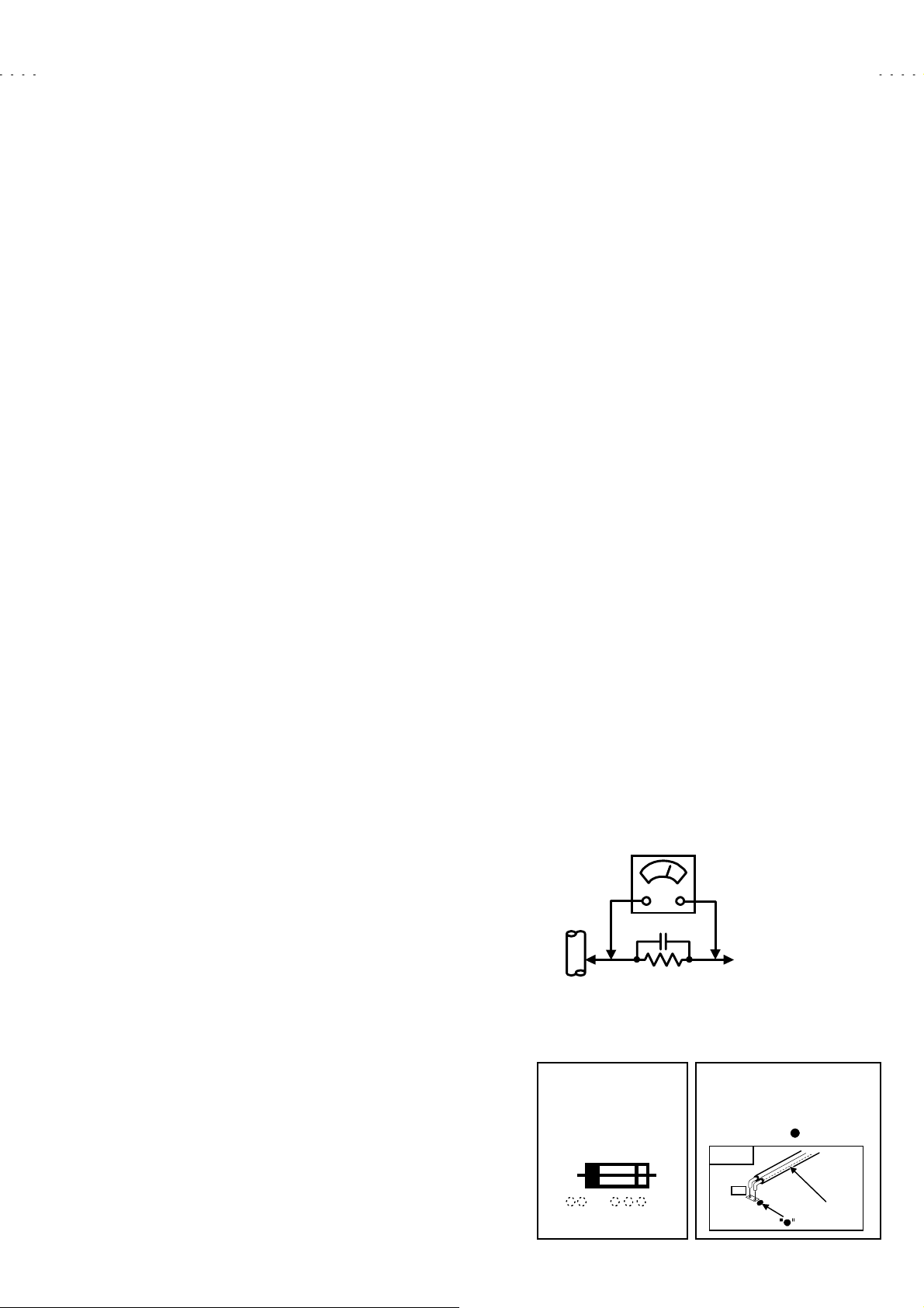
isolati on trans former duri ng this check. ). Us e an AC voltmeter
having 1000 ohms per volt or more sensitivity in the following
manner. Connect a 1500Ω 10W resistor paralleled by a 0.15μF
AC -type c apaci tor b etween an exposed metal p art an d a known
good earth ground (water pipe, etc.). Measure the AC voltage
across the resistor with the AC voltmeter. Move the resistor
connection to each exposed metal part, particularly any exposed
metal part having a return path to t he chassis, and measure the
AC voltage ac ros s th e resi st or. Now, rever s e the pl ug i n t he AC
outlet and repeat each measurement. Any voltage measured must
not exc eed 0.75V AC (r .m.s.). This c orresponds to 0.5mA AC
(r.m.s.).
However , in t ropi cal area, t his must n ot exceed 0. 3 V AC ( r.m . s.).
This corresponds to 0.2mA AC (r.m.s.).
AC VOLTMETER
(HAVING 1000
GOOD
EARTH
GROUND
11. High voltage hold down circuit check.
After repair of the high voltage hold down circuit, this circuit shall
be checked to operate correctly.
See item "How to check the high voltage hold down circuit".
This mark shows a fast
operating fuse, the
letters indicated below
show the rating.
0.15μF AC-TYPE
1500
10W
Ω
OR MORE SENSITIVITY)
PLACE THIS PROBE
ON EACH EXPOSED
METAL PART
POWER CORD
REPLACEMENT WARNING.
Connecting the line side of
power cord to " " mark side.
PWB
PW
A V
/V,
Ω
LINE
No.51775B
1-3
Page 4
A
V-61S902
SPECIFIC SERVICE INSTRUCTIONS
SERVICE REPLACE CORRESPONDENCE
The following service policy is being utilized.
Item Part number Service method
MAIN PWB ASS’Y
RECEIVER PWB ASS’Y
AV SELECTOR PWB ASS’Y
COMPONENT INPUT PWB ASS’Y
REAR JACK PWB ASS’Y
I-P CONVERT. PWB ASS’Y
3D YC SEP. MODULE
SUB COLOR DEMOD. MODULE
RGB PROCESS MODULE
SURROUND MODULE
MAIN DRIVE PWB ASS’Y
POWER PWB ASS’Y
LINE FILTER PWB ASS’Y
IGNITER PWB ASS’Y
LED PWB ASS’Y
FRONT JACK PWB ASS’Y
FRONT CONTROL PWB ASS’Y
REMO-CON SENSOR PWB ASS’Y
DIGITAL INPUT MODULE
SUB DRIVE MODULE
OPTICAL BLOCK
SCREEN
✻
✻1 : DIGITAL INPUT MODULE is supplied as assembled the service short jumper.
✻✻
✻
✻2 : SUB DRIVE MODULE is supplied as assembled the OPTICAL BLOCK and 2 memory ICs.
✻✻
✻
✻3 : OPTICAL BLOCK is supplied as assembled the SUB DRIVE MODULE and 2 memory ICs.
✻✻
✻
✻4 : SCREEN is supplied as assembled the screen frame and other screen parts.
✻✻
✻✻✻✻4
OPTICAL BLOCK is included the D-ILA HOLOGRAM device.
OPTICAL BLOCK is not included the projection lens .
✻✻✻✻3
✻✻✻✻1
✻✻✻✻2
SPD-1002A
SPD-0R002A
SPD-0R101A
SPD-0J002A
SPD-0J101A
SPD-0D001A
SHI-0Y021A
SHI-0V131A
SPD-0V002A
SPD-0A001A
SPD-1101A
SPD-9001A
SPD-9102A
SPD-9201A
SPD-7001A
SPD-7101A
SPD-7202A
SPD-7301A
902CP-S
902OP-S
902OP-S
902SC-S
Replace parts
Replace parts
Replace parts
Replace parts
Replace parts
Replace (module)
Replace (module)
Replace (module)
Replace (module)
Replace (module)
Replace (module)
Replace parts
Replace parts
Replace parts
Replace parts
Replace parts
Replace parts
Replace parts
Replace (assembly)
Replace (assembly)
Replace (assembly)
Replace (assembly)
1-4
No. 51775B
Page 5

A
SERVICE PARTS KIT INSTRUCTIONS
Due to the character of this product, these 3 parts kits are prepared.
Please note these matters when replacing or ordering the parts.
1. 902OP-S : OPTICAL UNIT
"
CONTENTS
➀
D-ILA HOLOGRAM device
Optical block (without the IGNITER PWB ASS’Y and the Projection lens)
➁
SUB DRIVE MODULE (SPD-3001A)
➂
Memory IC with adjusted data for the MAIN DRIVE PWB ASS’Y (SPD-1101A : IC147)
➃
Memory IC with adjusted data for the MAIN PWB ASS’Y (SPD-1002A : IC702)
➄
"
PRECAUTION FOR USING
1) When it is required to replace one of these, replace this kit. Replace all components of this kit.
: D-ILA HOROGRAM device, Optical block, SUB DRIVE PWB ASS’Y, IC147 (MAIN DRIVE PWB ASS’Y) or IC702 (MAIN PWB ASS’Y)
The memory IC stored adjustment data. So it is required to replace all parts together.
2) When replace the MAIN DRIVE PWB ASS’Y, take off the memory IC (IC147) from the original board and replace with new one.
When replace the MAIN PWB ASS’Y, do same manner. Replace memory IC (IC702).
3) After the replacement of the Optical block, objective lens focus adjustment is required.
2. 902CP-S : DIGITAL INPUT (HDCP) UNIT
"
CONTENTS
➀
DIGITAL INPUT MODULE (SPD-7801A)
Short jumper
➁
V-61S902
"
PRECAUTION FOR USING
1) The DIGITAL INPUT MODULE does not function correctly when the rear cover is opened.
It is required to insert the short jumper on the connector when it is required to operate it with the ear cover open condition.
2) In case of if the short jumper did not used, it is required initializing the DIGITAL INPUT MODULE.
3) Do not forget to take off the short jumper after the replacement.
3. 902SC-S : SCREEN ASS’Y
"
CONTENTS
➀ Fresnel lens
Double lenticular lens
➁
Screen shield
➂
Screen frame
➃
Screen holders and brackets
➄
"
PRECAUTION FOR USING
1) The screen is supplied as above assembly form.
No. 51775B
1-5
Page 6
A
V-61S902
REQUIREMENTS FOR SETTING
""""
GENERAL
This product contains 4 internal fans. There is risk of internal overheating if the fan intakes and exits are obstructed. In event the internal
temperature increases excessively, a sensor functions to cut off the power. Therefore, when using the product, check that the fan intakes
and exhausts are not blocked by dust and there is adequate free space around the unit to allow ample ventilation.
Intake hole
Exhaust hole
LAMP UNIT
""""
GENERAL
!
! The lamp emits high intensity white, ultraviolet and infrared light.
!!
Do not look directly at the light during service.
Also, do not touch the lamp directly as it presents a burn hazard.
!
! Hand le with extra care. This projector lamp emits high heat and contain s high-pressure during use.
!!
!
! Do n ot give any impact as this may cause the broken lamp.
!!
!
! Do n o t put foreign objects near the ventilation holes as this can result in fire or electrical hazards.
!!
Do not block the ventilation holes as this may cause the internal temperature to rise an d possibly result fire.
"
" PRECAUTION FOR REPLACEMENT
""
( Do not replace the light- source lamp immediately after the projector has been used.
The temperature of the light- source lamp is still high and could cause a burn.
Allow a cooling period of one hour or more before performing replacement.
( Before starting light-source lamp replacement work, turn off the MAIN POWER switch, and disconnect the power cord from the wall
outlet.
( If touched, the lamp glass surface (bulb) may rupture and burns may result.
Do not touch the glass portion or metal portion. Handle only plastic handle.
1-6
No. 51775B
Page 7
A
SCREEN
"
" GENERAL
""
( The screen assembly is made from the double lenticular lens, fresnel lens and the screen shield.
The anti static proceeding and the AR coating cover the surface of the lenticular lens.
Rubbing the surface with something hard, the coating may peel off.
When the screen is dirty, gently wipe it with a soft cloth.
If the screen is very dirty, wipe it down with a cloth dipped in a diluted kitchen cleaner (neutrality detergent) and thoroughly wrung-out.
Then wipe immediately after with a clean, dry cloth.
Never use the organic solvent such as the alcohol or benzine.
The screen assembly replacement is required if the coating was peel off.
Alkaline detergent or acidity detergent can not be used.
( The notched side of the double lenticular lens and the fresnel lens are faced each other.
Do not rub the screen when cleaning it or replacing it.
Rubbing the screen may cause of the scratch of the screen by its notch.
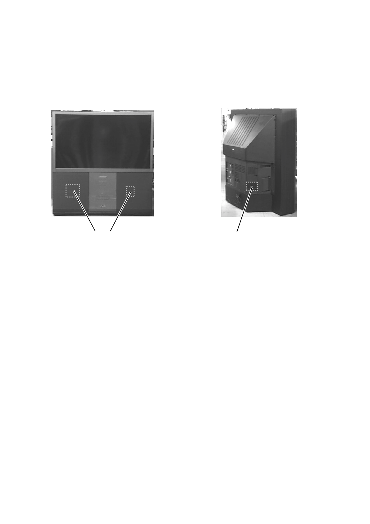
D-ILA HOLOGRAM DEVICE
"
" STRUCTURE
""
V-61S902
Glass substrate
Liquid
crystal
RG
H:1280pixels X 3colors
1.22
B
inches
V:1028pixels
Effective pixcel measurment
B
B
RG
drive IC
incident
light
Glass spacer
RG
B
Horogram
color
filtor
protection
membrane
transpealancy
electrode
orientational
membrane
RG
Refrevtive
pixel
electrode
"
" SPECIFICA TION
""
Pixel numbers
aperture ration
Horizontal : 1280pixels × 3colors, Vertical : 1028pixels
90.3%
No. 51775B
1-7
Page 8

A
V-61S902
DISASSEMBLY PROCEDURE
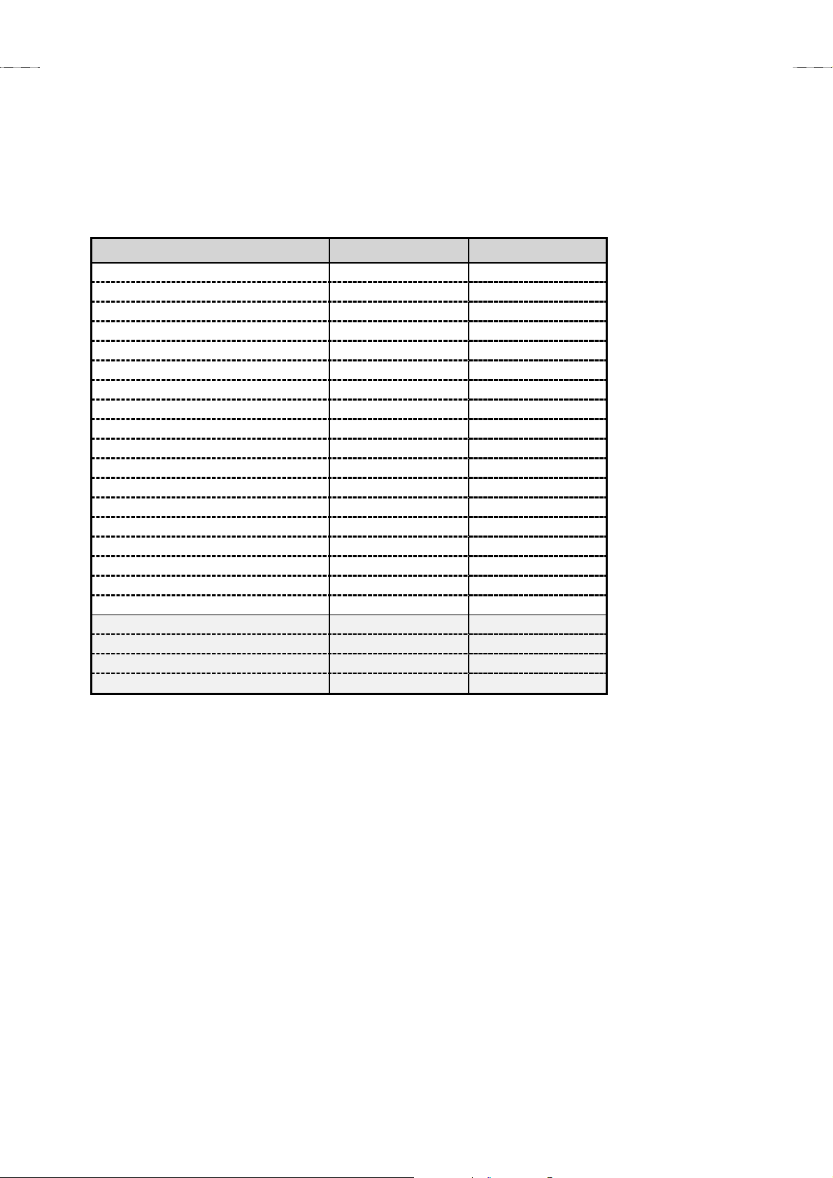
1. FRONT SIDE -1
SPEAKER GRILLE
1) Pull outward and remove 2 adhesive tapes [A]. Take out the
SPEAKER GRILLE.
! Both left and right have the same construction.
UPPER FRONT PANEL
● Take out the left and right SPEAKER GRILLES.
1) Remove 4 screws [B] and take out the UPPER FRONT PANEL.
FRONT CONTROL PWB ASS’Y
● Take out the UPPER FRONT PANEL.
1) Disengage interior connectors (X3 / X4).
2) Remove 6 screws [C] and take out the FRONT CONTROL PW B
ASS’Y.
LOWER FRONT PANEL
● Take out the left and right SPEAKER GRILLES.
1) Remove 4 screws [D] and take out the LOWER FRONT PANEL.
FRONT JACK PWB ASS’Y
● Take out the LOWER FRONT PANEL.
1) Disengage interior connectors (AM / F).
2) Remove 2 screws [E] and 2 screws [F]. Take out the FRONT
JACK PWB ASS’Y.
ADJUSTMENT COVER
" Take out the ADJUSTMENT COVER when using a personal
computer for adjustment.
● Take out the right SPEAKER GRILLE.
1) Loosen 4 screws [G].
2) Pull upward and take out the ADJUSTMENT COVER.
! When adjustment used the PC, connect the PC to the adjustment
terminal (RS-232C control : D-sub 9-pin connector) .
FILTER COVER
" Take out the FILTER COVER when take out the LAMP FILTER
COVER and replacing the LAMP UNIT.
● Take out the left SPEAKER GRILLE.
1) Loosen 4 screws [H].
2) Pull upward and take out the FILTER COVER.
BASS SPEAKER
● Take out the left and right SPEAKER GRILLES.
1) Support the speaker front and take out 4 screws [J].
2) Disengage the connecting wires and take out the BASS
SPEAKER.
! Both left and right have the same construction.
! The BASS SPEAKER are heavy. Use care not to drop or
damage them.
SCREEN ASS’Y
● Take out the left and right SPEAKER GRILLES.
1) Remove 2 screws [K].
2) Pull upward and take out the SCREEN ASS’Y.
! Use care not to scratch the front of the screen
! When transporting, avoid grasping the top of the SCREEN ASS’Y.
Grasp the left and right sides or bottom.
! When reassembling, observe the left and right pins of the cabinet
are engaged with the rear left and right hooks of the frame at
SCREEN ASS’Y. Also check insertion into the 3 slits at the
lower front of the cabinet.
MIRROR
! Wear protective gloves to avoid contaminating the MIRROR.
● Take out the SCREEN ASS’Y.
1) Remove 4 left and right screws [L] together with the holder.
2) Support upper part of the MIRROR, remove 6 screws [M]
together with the holder and take out the MIRROR.
! The MIRROR is heavy and easily broken. Use care not to
impart physical shock.
REMOTE CONTROL SENSOR PWB ASS’Y
● Take out the SCREEN ASS’Y.
1) Remove 1 screw [N] and take out the REMOTE CONTROL
SENSOR PWB ASS’Y.
! Since the projector lens is nearby, use care not to soil or scratch
the lens projection side.
MAIN SPEAKER
● Take out the left and right SPEAKER GRILLES.
1) Remove 4 screws [I].
2) Disengage the connecting wires and take out the MAIN
SPEAKER.
! Both left and right have the same construction.
1-8
No. 51775B
Page 9

A
1. FRONT SIDE -1
SCREEN ASS’Y
K
MIRROR
M
V-61S902
ADJUSTMENT
COVER
REMOTE CONTROL
SENSOR PWB ASS’Y
L
G
SPEAKER GRILLE
A
B
FRONT PANEL
FRONT
CONTROL
PWB ASS’Y
UPPER
D
E
LOWER
FRONT PANEL
C
FRONT JACK
PWB ASS’Y
F
J
BASS SPEAKER
MAIN SPEAKER
I
N
H
FILTER
COVER
No. 51775B
1-9
Page 10

A
V-61S902
2. FRONT SIDE -2
FRONT BORAD
● Take out the UPPER FRONT PANEL.
● Take out the LOWER FRONT PANEL.
● Take out the SCREEN ASS’Y.
1) Remove 14 screws [A].
2) Disengage the MAIN SPEAKER connecting wires outward and
take out the FRONT BOARD.
LAMP SECTION FILTER
" The LAMP SECTION FILTER can be replaced by the user.
● Take out the FILTER COVER.
1) Loosen 2 screws [B] and 1 screw [C], then take out the LAMP
SECTION FILTER.
! The filter is coupled with the protector circuit power interlock
switch. Be sure to reinstall the dust filter carefully in its proper
position. Secure with screws.
LAMP COVER
● Take out the FILTER COVER.
1) Loosen 2 screws [D] and 1 screw [C], then take out the LAMP
COVER (with lamp cover case) .
! The LAMP COVER can be disassembled by removing 4 screws
[E].
INTERLOCK SWITCH & COOLING FAN (INTAKE)
● Take out the FRONT COVER.
1) Remove 4 screws [K].
2) Remove 1 screw [L] and take out the switch bracket.
3) Disengage connector (L) and take out the INTERLOCK SWITCH.
4) Remove 2 screws [M] (with washers) .
5) Disengage connector (O) and take out the INTAKE COOLING
FAN.
! When taking out the INTAKE COOLING FAN, use care not to
misplace the 2 bushes.
LAMP UNIT
" The LAMP UNIT [PK-CL200U] can be replaced by the user.
" Allow plenty of time to cool after cutting the power, start the work.
● Take out the LAMP COVER.
1) Use a hex wrench (3mm diameter) to loosen 2 screws [F].
2) Grasp and pull the handle outward, then take out the LAMP
UNIT.
! A 3mm hex wrench is provided as an accessory.
DEVICE SECTION FILTER
" The DEVICE SECTION FILTER can be replaced by the user.
● Take out the ADJUSTMENT COVER.
1) Loosen 1 screw [G] and take out the DEVICE SECTION COVER.
FILTER PANEL
" The FILTER PANEL is taken out when connecting a personal
computer for adjustment.
● Take out the ADJUSTMENT COVER.
1) Remove 2 screws [H] and take out the FILTER PANEL.
! When adjustment used the PC, connect the PC to the adjustment
terminal (RS-232C control : D-sub 9-pin connector) .
! The FILTER PANEL can be separated into upper and lower by
removing 1 screw [I].
FRONT COVER
● Take out the FRONT BOARD.
1) Remove 14 screws [J].
2) Disengage the speaker connector (R), then pull outward and take
out the FRONT COVER.
! When taking out the FRONT COVER, use care not to snag the
speaker wire clamp.
1-10
No. 51775B
Page 11

A
2. FRONT SIDE -2
Front air duct
K
V-61S902
INTERLOCK SWITCH
Lamp cover case
LAMP COVER
B
C
B
LAMP SECTION
FILTER
L
INTAKE
COOLING
E
D
A
FRONT BOARD
FAN
LAMP
UNIT
M
F
FRONT COVER
J
H
I
G
FILTER PANEL (upper)
DEVICE SECTION FILTER
FILTER PANEL (lower)
No. 51775B
1-11
Page 12

A
V-61S902
3. OPTICAL BLOCK SECTION
SUB DRIVE PWB ASS’Y
● Take out the FRONT COVER.
1) Disengage the connector (017) of the MAIN DRIVE PW B ASS’Y
and SUB DRIVE PWB ASS’Y.
2) Carefully disengage the device unit connector (018). Extract
gradually to avoid damaging the connector.
3) Remove 2 screws [A] and take out the SUB DRIVE PWB ASS’Y.
! The flat wire connecting the DEVICE UNIT is easily damaged.
Handle very carefully.
OPTICAL BLOCK
" Allow plenty of time to cool after cutting the power, start the work.
● Take out the LAMP UNIT.
● Take out the FRONT COVER.
1) Disengage the connector (017) of the MAIN DRIVE PW B ASS’Y
and SUB DRIVE PWB ASS’Y.
2) Disengage connectors (AR / AE / AF / AG / AX).
3) Remove 3 screws [B].
4) While using care not to strike the SUB DRIVE PWB ASS’Y,
cabinet or other components, gradually pull the OPTICAL BLOCK
outward and set it downward.
! A spacer (cushion) is attached to the optical block lens section.
! The OPTICAL BLOCK contains prism, mirrors and other
precision components. When handling the OPTICAL BLOCK,
use care not to drop it or subject it to strong physical shock.
! Use care not to directly touch or contaminate the lens projection
side.
DEVICE UNIT
" The DEVICE UNIT contains the D-ILA HOLOGRAM device and
prism.
" The DEVICE UNIT is supplied as assembled the OPTICAL
BLOCK.
● Take out the FRONT COVER.
1) Remove 8 screws [D] and take out the optical block cover.
2) Carefully disengage the SUB DRIVE PWB ASS’Y connector
(018). Extract gradually to avoid damaging the connector.
3) Remove 2 screws [F] and take out the device holder.
4) While using care not to directly touch the prism, grasp and
disengage the bracket from the leaf spring, and take out the
DEVICE UNIT.
! By no means separate the prism and D-ILA HOLOGRAM device.
Performance of the factory-matched pair is virtually impossible to
restore.
! The flat wire connecting the SUB DRIVE PWB ASS’Y is easily
damaged. Handle very carefully.
! The DEVICE UNIT position is carefully determined and secured
to the prism by the leaf spring. During reassemble, precisely
insert into the leaf spring.
THERMAL SENSOR (THERMOSTAT)
● Take out the LAMP UNIT.
1) Remove 2 screws [G] and take out the sensor cover.
2) Remove 2 screws [H] and take out the sensor bracket.
3) Take out the sensor holder and disengage connector (M). Take
out the THERMAL SENSOR.
PROJECTION LENS
● Take out the OPTICAL BLOCK.
1) Remove 4 screws [C] and take out the PROJECTION LENS.
! When replace the PROJECTION LENS, adjust the lens focus.
! A spacer (cushion) is attached to the PROJECTION LENS.
! The PROJECTION LENS is heavy. When handling the PRO-
JECTION LENS, use care not to drop it or subject it to strong
physical shock.
! Use care not to directly touch or contaminate the lens projection
side.
OPTICAL SECTION COOLING FAN (INTAKE)
● Take out the FRONT COVER.
1) Remove 8 screws [D] and take out the optical block cover.
2) Remove 4 screws [E].
3) Disengage connector (AG) and take out the INTAKE COOLIN G
FAN.
! When the optical block cover is taken out, the internal
components are easily prone to physical shock and
contamination. Use care not to damage or soil the internal
components.
IGNITER PWB ASS’Y
● Take out the OPTICAL BLOCK.
1) Remove 2 screws [I] and 1 screw [J], then take out the igniter
bracket.
2) Take out the lamp contacter (electrode section) from the
OPTICAL BLOCK.
3) Remove 4 screws [K] and take out the igniter cover together with
the IGNITER PWB ASS’Y.
! Use care not to misplace the 4 bushes when removing the
screws.
1-12
No. 51775B
Page 13

A
3. OPTICAL BLOCK SECTION
V-61S902
LAMP
UNIT
D
Optical block cover
IGNITER PWB ASS’Y
Igniter cover
OPTICAL BLOCK
B
E
INTAKE
COOLING FAN
A
Device
holder
K
I
C
B
DEVICE UNIT
(D-ILA HOLOGRAM
F
device & prism)
J
SUB DRIVE
PWB ASS’Y
Sensor
holder
H
G
Sensor
cover
THERMAL SENSOR
(THERMOSTAT)
Sensor bracket
No. 51775B
1-13
Page 14

A
V-61S902
4. REAR SIDE
REAR COVER
1) Remove 17 screws [A] and 6 screws [B].
2) Take out the power cord panel and pull out the power cord
through the hole.
3) Take out the REAR COVER.
REAR SIDE PANEL
● Take out the REAR COVER.
1) Remove 6 screws [C].
! Both left and right have the same construction.
REAR TERMINAL BOARD
● Take out the REAR COVER.
1) Remove 7 screws [D] and 3 screws [E] (with washers).
2) Pull outward and take out the REAR TERMINAL BOARD.
DIGITAL INPUT PWB ASS’Y
● Take out the REAR TERMINAL BOARD.
1) Remove 2 screws [F] and take out the DIGITAL INPUT PWB
ASS’Y.
MAIN CHASSIS EXTRACTION and STANDING
● Take out the REAR COVER.
● Take out the REAR TERMINAL BOARD.
● Take out the REMOTE CONTROL SENSOR PWB ASS’Y.
● Take out the FRONT JACK PWB ASS’Y.
" Prepare a 30cm high by 60cm wide seating for standing the MAIN
CHASSIS.
1) Where necessary, disengage the clamps at the MAIN CHASSIS
perimeter.
2) Grasp both sides of the rear and pull the MAIN CHASSIS
outward.
3) Disengage the MAIN CHASSIS front clamps.
4) Disengage 5 tabs [G] at the MAIN CHASSIS bottom and take out
the front board base (FRONT CONTROL PWB ASS’Y).
5) Position the front downward, extract and set the MAIN CHASSIS
on its side on the seating with the rear terminal section at the left
side in the bottom base.
! As required for operation checks, attach the FRONT CONTROL
PWB ASS’Y, REMOTE CONTROL SENSOR PWB ASS’Y and
other components.
! The MAIN CHASSIS is quite heavy. Care is needed in handling,
particularly to prevent toppling over when stood on its side.
LINE FILTER SECTION
● Extract the MAIN CHASSIS.
1) Remove 2 screws [K], 3 screws [M] and 1 screw [N].
! The LINE FILTER PWB ASS’Y, shield cover, drive section
EXHAUST COOLING FAN and overall EXHAUST COOLING
FAN are attached to the line filter board base.
MAIN DRIVE PWB ASS’Y
● Extract the MAIN CHASSIS.
1) Disengage connector (017).
2) Support the MAIN DRIVE PWB ASS’Y and remove 4 screws [O].
3) Disengage connectors (AA/AC/AN/C/W) and take out the MAIN
DRIVE PWB ASS’Y.
! The shield cover is attached by tabs at both sides of the MAIN
DRIVE PWB ASS’Y.
DRIVE SECTION COOLING FAN (EXHAUST)
● Extract the MAIN CHASSIS.
1) Remove 2 screws [H] and take out the fan bracket.
2) Remove 2 screws [I] (with washers).
3) Disengage connector (AQ) and take out the drive section
EXHAUST COOLING FAN.
OVERALL COOLING FAN (EXHAUST)
● Extract the MAIN CHASSIS.
1) Remove 2 screws [J] and 2 screws [K], then take out the fan
bracket.
2) Remove 2 screws [L].
3) Disengage connector (P) and take out the overall EXHAUST
COOLING FAN.
1-14
No. 51775B
Page 15

A
V-61S902
ASS
4. REAR SIDE
LINE FILTER
PWB ASS’Y
Line filter
board base
Shield cover
DIGITAL INPUT
PWB ASS’Y
E
COOLING FAN
(smaller)
I
M
F
H
COOLING FAN
(larger)
L
N
FRONT
CONTROL
PWB ASS’Y
G
K
J
MAIN
DRIVE
C
Front
board
base
O
C
B
B
PWB
’Y
D
REAR TERMINAL BOARD
MAIN CHASSIS
A
REAR COVER
REAR SIDE PANEL
No. 51775B
1-15
Page 16

A
V-61S902
REPLACEMENT OF CHIP COMPONENT
! CAUTIONS
1. Avoid heating for more than 3 seconds.
2. Do not rub the electrodes and the resist parts of the pattern.
3. When removing a chip part, melt the solder adequately.
4. Do not reuse a chip part after removing it.
! SOLDERING IRON
1. Use a high insulation soldering iron with a thin pointed end of it.
2. A 30w soldering iron is recommended for easily removing parts.
! REPLACEMENT STEPS
1.
How to remove Chip parts
"
" Resistors, capacitors, etc.
""
(1) As shown in the figure, push the part with tweezers and
alternately melt the solder at each end.
(2) Shift with tweezers and remove the chip part.
"
" Transistors, diodes, variable resistors, etc.
""
(1) Apply extra solder to each lead.
SOLDER
SOLDER
2. How to install Chip parts
"
" Resistors, capacitors, etc.
""
(1) Apply solder to the pattern as indicated in the figure.
(2) Grasp the chip part with tweezers and place it on the solder.
Then heat and melt the solder at both ends of the chip part.
"
" Transistors, diodes, variable resistors, etc.
""
(1) Apply solder to the pattern as indicated in the figure.
(2) Grasp the chip part with tweezers and place it on the solder.
(3) First solder lead A as indicated in the figure.
A
(2) As shown in the figure, push the part with tweezers and
alternately melt the solder at each lead. Shift and remove the
chip part.
Note : After removing the part, remove remaining solder from the
pattern.
1-16
C
(4) Then solder leads B and C.
A
C
No. 51775B
B
B
Page 17

A
V-61S902
SERVICE ADJUSTMENTS
ADJUSTMENT PREPARATION
1. You can make the necessary adjustments for this uni t with either the remote control unit or with the adjustment equipment and
parts as given below. Adjustment with the remote control unit is made on the basis of the initial setting values, however, the new
setting values which set the screen to its optimum c ondition may differ from the initial settings.
2. Turn on the power for the set and test equipment before use, and start the adjustment procedures after waiting at least 30 minutes.
3. Make sure that AC power is turned on correctly.
4. Unless otherwise specified, prepare the most suitable reception or input signal for adjustment.
5. Never touch any adjustment parts, which are not specified in the list for this adjustment-variable resistors, transformers, condensers, etc.
6. Preset the items in the “SETTINGS BEFORE ADJUSTMENTS” with the remote control unit before adjustment.
MEASURING INSTRUMENT
1. DC voltmeter (or Digital voltmeter)
2. Oscilloscope
3. Frequency counter
4. TV audio multiplex signal generator
5. Signal generator (Pattern generator) [NTSC (composite / component) / 480p (component / digital-in) / 1080i (component / digital-in)]
6. Remote control unit [RM-C308]
SETTINGS BEFORE ADJUSTMENTS
Be sure to set the items as follows before adjusting.
Setting item Mode Setting item Mode
ASPECT PANORAMA SOUND (SURROUND) OFF
VIDEO STATUS STANDARD BBE OFF
NATURAL CINEMA OFF BASS CENTER
YNR CENTER TREBLE CENTER
DNR OFF BALANCE CENTER
SUPER BASS MID
ADJUSTMENT LOCATIONS
MAIN PWB ASS'Y MAIN DRIVE PWB ASS'Y
RECEIVER
PWB ASS'Y
AV SELECTOR
PWB ASS'Y
I-P CONVERT.
PWB ASS'Y
TP-290
TP-390
TP-490
SUB COLOR
DEMOD.
MODULE
RGB
PROCESS
MODULE
REAR JACK PWB ASS'Y
TP-RY
TP-BY
No. 51775B
FRONT (TOP)
1-17
Page 18

A
V-61S902
p
SERVICE MENU BASIC OPERATION
1. ENTRY
1) Press the [SLEEP TIMER] key and set for “0 MIN.”.
2) While “0 MIN.” is displayed, simultaneously press the [DISPLAY] and [VIDEO STATUS] keys to display the SERVICE (main) MENU.
3) Select the respective adjustment menus with the numeral keys. Return from adjustment to the main menu by pressing the [EXIT] key.
2. RELEASE
At the main menu, press the [EXIT] key to release the service mode.
The service mode is also released by pressing [EXIT] key at the < 5. I2C BUS CTRL > and the < 9. SELF CHK > adjustment menus.
3. OPERATION
Use the following keys for adjustments.
VOL
++++
/ CH
/ VOL
++++
----
✻
Adjustment range differs with the item.
----
Change adjustment item CH
Change adjustment value
Record adjustment value MUTING
Be sure to press the [MUTING] key after changing the adjustment value. If another operation (e.g., screen size or video select) is selected
without pressing the [MUTING] key, the adjustment is cancelled without changing the value.
4. SERVICE MENU OUTLINE
! 1. PICTURE/SOUND
Settings for video, audio, device drive and other adjustments
Signal system
Screen size
Video status
Lamp use time
Set internal
temperature
Item number
Adjust m e n t values
I-P conversion block
through status
Progressive
conversion mode
MTS status
Signal conversion
status
Front latch status
! 2. YC SEP
Setting to couple 3-dimensional comb filter (YC separator)
! 5. I2C BUS STOP
Inter-IC bus control on/off
! 6. PP
Adjustment and setting for twin picture
! 7. IP
I-P conversion setting
! 8. RF AFC
AFT setting for main and sub tuners
! 9. SELF CHK
Present status and history indication detected by self-diagnostic function
" <2. YC SEP>, <5. I2C BUS STOP>, <7. IP> and <8. RF AFC> are normall y
not user in service. The setting values are fixed and should not be
changed.
NTSC : 480i composite (or Y/C) signal
DVD : 480i component (Y/P
ED : 480p component (Y/P
HD : 1080i component (Y/P
B/PR
B/PR
B/PR
) signal
) signal
) signal
HDCP 480p : Digital-in (DVI) 480p signal
HDCP 1080i : Digital-in (DVI) 1080i signal
PANORAMA / CINEMA / FULL / REGULAR
STANDARD / THEATER
Time projection lamp is used (in minutes)
Device drive area temperature
A : Audio system / B : Video system /
D: Device drive / F : Settings (fixed)
Adjustment status for each item
ON : Through
OFF : Process
LINE : Inter-line (Internal field) process
FRAME : Inter-frame process
MTS signal detect status
Connection detect at S-video input terminal
Front control latch IC detect status
SERVICE MENU
1. PICTURE/SOUND
2. YC SEP
3.
4.
5. I2C BUS CTRL
6. PP
7. IP
8. RF AFC
9. SELF CHK
Main menu
Signal
system
NTSC PANORAMA STANDARD
Adjustment value
Lam
use time
0080:25 +035C
Item
No.
A01 000 OFF LINE
XXXXXX
MTS
status
adjustment and setting screen
Screen
size
Progressive conversion
I-P
conversion
through status
XXXXXXXXXX XXXXXXXX
11
Signal
switching
status
< 1.PICTURE/SOUND >
Video
status
Set internal
temperature
Front latch
status
1-18
No. 51775B
Page 19

A
V-61S902
SERVICE MENU APPEARANCE
Press the numeral keys to open the adjustment menus.
Return to the main menu by pressing the [EXIT] key. At the <5. I2C BUS CTRL> and <9. SELF CHK> adjustment menus, pressing the [EXIT]
key closes the service mode without returning to the main menu.
Normally not used in service
SERVICE MENU
1. PICTURE/SOUND
2. YC SEP
3.
4.
5. I2C BUS CTRL
6. PP
7. IP
8. RF AFC
9. SELF CHK
YC01 000
Main menu < 2. YC SEP > setting screen
NTSC PANORAMA STANDARD
0080:25 +035C
A01 000 OFF LINE
XXXXXX
XXXXXXXXXX XXXXXXXX
11
I2C BUS OFF
< 1. PICTURE/SOUND > adjust screen < 5. I2C BUS CTRL > setting screen
Adjustment
item
Adjustment
value
IP001 000 NTSC OFF LINEPPS001 00000
< 6. PP > adjust screen < 7. IP > setting screen
TEMP OK LAMP NG 2
FAN OK MPOW OK
5VPR OK LMEM OK
SYNC M : OK S : OK HD : NG
MEM OK AVSW OK
VCD NG 2
AIO OK YC OK
TUN OK
TUNER 1
RF AFC ON
FINE -10
PP OK IP OK
< 9. SELF CHK> display screen < 8. RF AFC > setting screen
Indicate status and history of self-diagnostic
No. 51775B
1-19
Page 20

A
V-61S902
ADJUSTMENT STEP
MULTI-SOUND DEMODULATION SYSTEM
""""
1. MTS INPUT LEVEL check
Instruments Remote control unit
Test point
Adjustment location 1. PICTURE/SOUND : A02 (Input level)
Preparation
1. Select [A02] of the <1. PICTURE/SOUND>.
2. Verify that [A02] is set at its initial setting value “36”.
2. MTS STEREO VCO
Remote control unit
Instruments
Test point MPX connector 2-pin [RECEIVER]
Adjustment location
Preparation
1. Receive a RF signal (nonmodulated sound signal) from the antenna terminal.
2. Select [A03] of the <1. PICTURE/SOUND> and change the setting value to 1.
3. Connect the frequency counter to 2-pin of [MPX] connector.
4. Select [A04].
5. Set the initial setting value of [A04].
6. Adjust [A04] so that the frequency counter will display 15.73kHz ± 0.1kHz.
7. Select [A03] of the <1. PICTURE/SOUND> and reset the setting value to 0.
Signal generator : Non modulated sound
Frequency counter
H
1. PICTURE/SOUND : A03 (F
monitor)
1. PICTURE/SOUND : A04 (Stereo VCO)
3. MTS SAP VCO
Remote control unit
Instruments
Signal generator : Non modulated sound
Frequency counter
ΩΩΩΩ
1M
resistor
Test point MPX connector 2-pin / 4-pin [RECEIVER]
H
Adjustment location
1. PICTURE/SOUND : A09 (5F
1. PICTURE/SOUND : A10 (SAP VCO)
monitor)
Preparation
1. Receive a RF signal (non-modulated sound signal) from the antenna terminal.
2. Connect between 4-pin of [MPX] connector and GND (3-pin of [MPX] connector) through 1MΩ Resistor.
3. Select [A09] of the <1. PICTURE/SOUND> and reset the setting value to 1.
4. Connect the frequency counter to 2-pin (R.OUT) of [MPX] connector.
5. Select [A10].
6. Set the initial setting value of [A10].
7. Adjust [A10] so that the frequency counter will display 78.67kHz ± 0.5kHz.
8. Select [A09] of the <1. PICTURE/SOUND> and reset the setting value to 0.
4. MTS FILTER check
Instruments Remote control unit
Test point
Adjustment location 1. PICTURE/SOUND : A06 (Pilot filter)
Preparation
1. Select [A06] of the <1. PICTURE/SOUND>.
2. Verify that [A06] is set at its initial setting value “27”.
1-20
No. 51775B
Page 21

A
5. MTS SEPARATION
Remote control unit
Instruments
TV audio multiplex signal generator
Oscilloscope
Test point MPX connector 1-pin / 2-pin [RECEIVER]
Adjustment location
1. PICTURE/SOUND : A07 (Low separation)
1. PICTURE/SOUND : A08 (High separation)
Preparation
1. Input a stereo L signal (300Hz) from the TV audio multiplex signal generator to the antenna terminal.
2. Connect the oscilloscope to 1-pin (L OUT) of [MPX] connector, and display one cycle portion of the 300Hz signal.
3. Change the connection of the oscilloscope to 2-pin (R OUT) of [MPX] connector, and enlarge the voltage axis.
4. Select [A07] of the <1. PICTURE/SOUND>.
5. Set the initial setting value of [A07].
6. Adjust [A07] so that the stroke element of the 300Hz signal will become minimum.
7. Change the signal to 3kHz, and similarly adjust the [A08].
: Sine wave (300Hz / 3kHz)
V-61S902
1 cycle
L-Channel
signal waveform
R-Channel
crosstalk portion
Minimum
No. 51775B
1-21
Page 22

A
V-61S902
"
" VIDEO SYSTEM
""
1. RGB BRIGHTNESS and CONTRAST STANDARD
Remote control unit
Instruments
Test point TP-390 [MAIN DRIVE]
Adjustment location
Preparation See [SETTINGS BEFORE ADJUSTMENTS] and set controls and switches accordingly.
Signal generator : NTSC / 480p / 1080i
#
#Test pattern : Gray scale (including 0% and 100% white peak)
##
Oscilloscope
1. PICTURE/SOUND : S03 (Brightness)
1. PICTURE/SOUND : S04 (Contrast)
1. PICTURE/SOUND : S16 (G cutoff)
1. PICTURE/SOUND : F33 (Digital enhancer off mode)
NTSC
1. Supply a gray scale pattern signal input.
2. Set the screen size to “PANORAMA”
3. Connect the oscilloscope to TP-390
$$$$
STAMDARD SETTING
4. Press the [VIDEO STATUS] key and set to “STANDARD”.
5. Select <1. PICTURE/SOUND>.
6. Select [S04] and adjust value A of the waveform as indicated in the figure.
7. Select [S03] and adjust value B.
8. Repeat steps 6 and 7 so that values A and B are as indicated in the figure.
Make a note of the [S03] and [S04] values.
$$$$
THEATER SETTING
9. Press the [VIDEO STATUS] key and set to “THEATER”.
10.Set [S04] and [S03] to the same values as “STANDARD”.
11.Select [S04] and set to the difference with respect to “STANDARD” is as indicated in the
table.
" Adjustment is not necessary for other screen sizes
" Be sure to press the [MUTING] key after each adjustment.
DVD / ED / HD (I-P through OFF)
Set to the following table conditions and adjust in the same manner as NTSC.
HD THROUGH (I-P through ON)
!
To set <HD THROUGH (I-P through ON)>, set [F33] to “1” and VIDEO STATUS to
“THEATER”.
Adjustment finished, select [F33] and return to “0”.
Select [S16] and adjust value B of the waveform as indicated in the figure.
####
SETTING
Mode
NTSC
DVD
ED
HD
THROUGH
HD
HDCP 480p
HDCP 1080i
[Unit : V]
WAVEFORM
####
A
AB
1.10
1.47
1.49 1.51
1.49 1.51
1.49 1.51
(no need)
1.51
1.49 1.51
1.49 1.51
B
0V
HDCP 480p / HDCP 1080i
Set to the following table conditions and adjust in the same manner as ED and HD.
In absence of a signal, copy the data for 480p / 1080i signal input and compensate for optimum status.
Mode Input terminal Input signal Screen size
DVD
ED
HD
HDCP 480p
HDCP 1080i
1-22
COMPONENT-VIDEO-IN NTSC component FULL
COMPONENT-VIDEO-IN Analog 480p FULL
COMPONENT-VIDEO-IN Analog 1080i (FULL)
DIGITAL-IN Digital RGB 480p FULL
DIGITAL-IN Digital RGB 1080i (FULL)
No. 51775B
THEATER
<S03> offset
00
00
00
00
00
THEATER
<S04> offset
Page 23

A
2. WHITE BALANCE
Remote control unit
Instruments
Test point TP-290 / TP-390 / TP-490 [MAIN DRIVE]
Adjustment location
Preparation Complete the [RGB BRIGHTNESS and CONTRAST STANDARD] adjustments.
NTSC
1. Supply a gray scale pattern signal input.
$$$$
STAMDARD SETTING
G OUTPUT >>
<<
2. Press [VIDEO STATUS] key and set for “STANDARD”.
3. Select <1. PICTURE/SOUND>.
4. Connect the oscilloscope channel 1 to TP-390.
<< R OUTPUT >>
5. Connect the oscilloscope channel 2 to TP-290.
6. Select [S10] and adjust the waveform component A to the same value as the G output
(see figure).
7. Select [S14] and adjust the waveform component B to the same value as the G output.
8. Repeat steps 6 and 7. Adjust the waveform components A and B to the same value as
the G output.
<< B OUTPUT >>
9. Connect the oscilloscope channel 2 to TP-490.
10.Select [S12] and adjust the waveform component A to the same value as the G output.
11.Select [S18] and adjust the waveform component B to the same value as the G output.
$
$ THEATER SETTING
$$
12.Press [VIDEO STATUS] key and set for “THEATER”.
13.Set [S10], [S14], [S12] and [S18] to the same values as “STANDARD” setting.
14.Repeat steps 10 and 11.
Adjust the waveform components A and B to the same value as the G output.
" Since white balance adjustment, be sure to align the RGB waveform amplitudes.
" Be sure to press the [MUTING] key after adjusting each item.
Signal generator : NTSC / 480p / 1080i
#
#Test pattern : Gray scale (including 0% and 100% white peak)
##
Oscilloscope
1. PICTURE/SOUND : S10 / S11 (R drive / R drive offset)
1. PICTURE/SOUND : S14 / S15 (R cutoff / R cutoff offset)
1. PICTURE/SOUND : S12 / S13 (B drive / B drive offset)
1. PICTURE/SOUND : S18 / S19 (B cutoff / B cutoff offset)
1. PICTURE/SOUND : F33 (Digital enhancer off mode)
WAVEFORM
####
A
V-61S902
B
0V
DVD / ED / HD (I-P through OFF) / HD THROUGH (I-P through ON)
Set to the following table conditions and adjust in the same manner as NTSC.
Note the <ED> adjustment items differ.
! To set <HD THROUGH (I-P through ON)>, set [F33] to “1” and [VIDEO STATUS] to
“THEATER”.
Adjustment finished, select [F33] and return to “0”.
HDCP 480p / HDCP 1080i
Adjust <HDCP 480p> and <HDCP 1080i> in the same manner as ED and HD.
In absence of a signal, copy the data for 480p / 1080i signal input and compensate for optimum status.
Note the <HDCP480p> adjustment items differ.
R output (TP-290) B output (TP-490)
Mode Input terminal Input signal
DVD COMPONENT-VIDEO-IN NTSC component <S10> <S14> <S12> <S18>
ED
HD
HD THROUGH COMPONENT-VIDEO-IN Analog 1080i <S10> <S14> <S12> <S18>
HDCP 480p
HDCP 1080i DIGITAL-IN Digital RGB 1080i <S10> <S14> <S12> <S18>
COMPONENT-VIDEO-IN Analog 480p
COMPONENT-VIDEO-IN Analog 1080i
DIGITAL-IN Digital RGB 480p
Value A
adjustment
item
<S11> <S15> <S13> <S19>
<S10> <S14> <S12> <S18>
<S11> <S15> <S13> <S19>
Value B
adjustment
item
Value A
adjustment
item
No. 51775B
Value B
adjustment
item
1-23
Page 24

A
V-61S902
3. SINGLE SCREEN COLOR and TINT
Remote control unit
Instruments
Test point TP-290 / TP-490 [MAIN DRIVE]
Adjustment location
Preparation
NTSC
1. Supply a color bar pattern signal input.
$
$ STAMDARD SETTING
$$
2. Connect the oscilloscope to TP-290.
3. Press the [VIDEO STATUS] key and set for “STANDARD”.
4. Select <1. PICTURE/SOUND>.
5. Select [S04] and apply corrections indicated in the table.
6. Select [S01] and adjust the waveform Y value as indicated in the table.
7. Select [S02] and adjust the waveform R value as indicated in the table.
8. Repeat steps 6 and 7. Adjust Y and R values as indicated in the table.
9. Connect the oscilloscope to TP-490.
10.Select [S07] and adjust the waveform B value as indicated in the table.
11.Select [S04], add the correction value and return to the previous mode.
$
$ THEATER SETTING
$$
12.Connect the oscilloscope to TP-290.
13.Press the [VIDEO STATUS] key and set to “THEATER”.
14.Select [S04] and add the correction value indicated below.
15.Select [S01] and adjust the waveform Y value as indicated in the table.
16.Select [S02] and adjust the waveform R value as indicated in the table.
17.Repeat steps 15 and 16. Adjust Y and R values as indicated in the table.
18.Connect the oscilloscope to TP-490.
19.Select [S07] and adjust the waveform B value as indicated in the table.
20.Select [S04], add the correction value and return to the previous mode.
Signal generator : NTSC / 480p / 1080i
#
#Test pattern : Color bar (75% white peak)
##
Oscilloscope
1. PICTURE/SOUND : S04 (Contrast)
1. PICTURE/SOUND : S01 (Color)
1. PICTURE/SOUND : S02 (Tint)
1. PICTURE/SOUND : S07 (B-Y gain)
See [SETTINGS BEFORE ADJUSTMENTS] and set controls and switches accordingly.
Complete the [RGB BRIGHTNESS and CONTRAST STANDARD] and [WHITE BALANCE]
adjustments.
TP-290 WAVEFORM
####
YYYYR
WY CGMR B
TP-490 WAVEFORM
####
WY CGMR B
R
RR
BBBB
DVD / ED / HD
In the same manner as NTSC, adjust the values according to the table.
HDCP 480p / HDCP 1080i
In the same manner as ED and HD, adjust the values according to the table.
In absence of a signal, copy the data for 480p / 1080i signal input and compensate for optimum status.
Mode STANDARD THEATER
Contrast
correction
<S04>
NTSC
DVD
ED
HD
HDCP 480p
HDCP 1080i
[Unit : V] (expect contrast correction)
-5 1.14 1.79 1.05 -5 1.08 1.32 1.44
-20 1.40 1.68 1.22 -20 1.42 1.51 1.72
-15 1.22 1.75 1.16 -10 1.79 1.82 1.21
-10 1.32 1.78 1.47 -5 1.53 1.68 1.80
-15 1.22 1.75 1.16 -10 1.79 1.82 1.21
-10 1.32 1.78 1.47 -5 1.53 1.68 1.80
1-24
Y (yellow)
adjustment
value
<S01>
R (red)
adjustment
value
<S02>
B (blue)
adjustment
value
<S07>
No. 51775B
Contrast
correction
<S04>
adjustment
Y (yellow)
value
<S01>
R (red)
adjustment
value
<S02>
B (blue)
adjustment
value
<S07>
Page 25

A
4. TWIN (SPLIT) SCREEN COLOR and TINT
e
Remote control unit
Instruments
Test point
Adjustment location
Preparation See [SETTINGS BEFORE ADJUSTMENTS] and set controls and switches accordingly.
1. Supply an NTSC color bar pattern signal input.
2. Press the [SPLIT] key and set for the twin (split) screen mode.
3. Select <6. PP> and use the [SWAP] key to display the same image in both screens.
4. Connect the oscilloscope to TP-RY (ground at I-P CONVERT. MODULE shield).
5. Select [PPA16] and set to where the left screen color difference center and pedestal are the same.
6. Select [PPA13] and set to where the right screen color difference center and pedestal are the same.
7. Connect the oscilloscope to TP-BY (ground at I-P CONVERT. MODULE shield).
8. Select [PPA17] and set to where the left screen color difference center and pedestal are the same.
9. Select [PPA14] and set to where the right screen color difference center and pedestal are the same.
10.Make a memo of these adjustment values and set the mode that left screen input is no signal to the same values.
✻ Setting items : [PPA13] / [PPA14] / [PPA16] / [PPA17]
11.Connect the oscilloscope to TP-290.
12.Supply an all black pattern signal input on the left screen.
13.Select [S04] of the <1. PICTURE/SOUND> and apply correction value “-5”.
14.Select [PPS04] and adjust the right screen waveform Y value to 1.21V.
15.Select [PPS01] and adjust the right screen waveform R value to 1.77V.
16.Repeat steps 14 and 15. Adjust for specified Y and R values.
17.Select [S04], apply correction and return to previous mode.
Signal generator : NTSC
#
#Test pattern : Color bar (75% white peak) / All black (0%)
##
Oscilloscope
TP-RY / TP-BY [MAIN]
TP-290 [MAIN DRIVE]
6. PP : PPA16 (Main highlight R-Y)
6. PP : PPA13 (Sub highlight R-Y)
6. PP : PPA17 (Main highlight B-Y)
6. PP : PPA14 (Sub highlight B-Y)
6. PP : PPS04 (Sub decoder color)
6. PP : PPS01 (Sub decoder tint)
1. PICTURE/SOUND : S04 (Contrast)
V-61S902
R-Y
waveform
B-Y
waveform
Waveform adjustment points
Eliminate step differenc
at circled component an
adjust for same level.
YYYYR
R
RR
1.77V1.21V
WYC GMR B
No. 51775B
1-25
Page 26

JVC SERVICE & ENGINEERING COMPANY OF AMERICA
DIVISION OF JVC AMERICAS CORP.
Head office : 1700 Valley Road, Wayne, New Jersey 07470 (973)315-5000
East Coast : 10 New Maple Avenue, Pine Brook, New Jersey 07058 (973)396-1000
Midwest : 705 Enterprise St. Aurora, Illinois 60504 (630)851-7855
West Coast: 5665 Corporate Avenue, Cypress, California 90630 (714)229-8011
Southwest : 10700 Hammerly, Suite 105, Houston,Texas 77043 (713)935-9331
Hawaii : 2969 Mapunapuna Place, Honolulu, Hawaii 96819 (808)833-5828
Southeast : 1500 Lakes Parkway , Lawrenceville, Georgia 30243 (770)339-2582
JVC CANADA INC.
Head office : 21 Finchdene Square Scarborough, Ontario M1X 1A7 (416)293-1311
Vancouver : 13040 Worster Court Richmond B.C. V6V 2B3 (604)270-1311
4
AV-61S902(US)
AV-61S902(CA)
Printed in Japan
VP 0107
K.K/T.K/H.K/M.H/A.N /DP
 Loading...