

Page 1
SERVICE MANUAL
REAR PROJECTION TELEVISION
AV-48WP74
AV-56WP74
BASIC CHASSIS
SB3
AV-48WP74
/HA
AV-56WP74 /HA
Supplementary
Since some details of the AV-48WP74/HA / AV-56WP74/HA service manual (No.52105 2003/4) were
incorrect , We are informing you of these errors and of the new correct descriptions.
ADDITION ITEM
The adjustment performed using test mode is added. For this reason, the item of “HOW TO ENTER THE
TEST MODE” was described below.
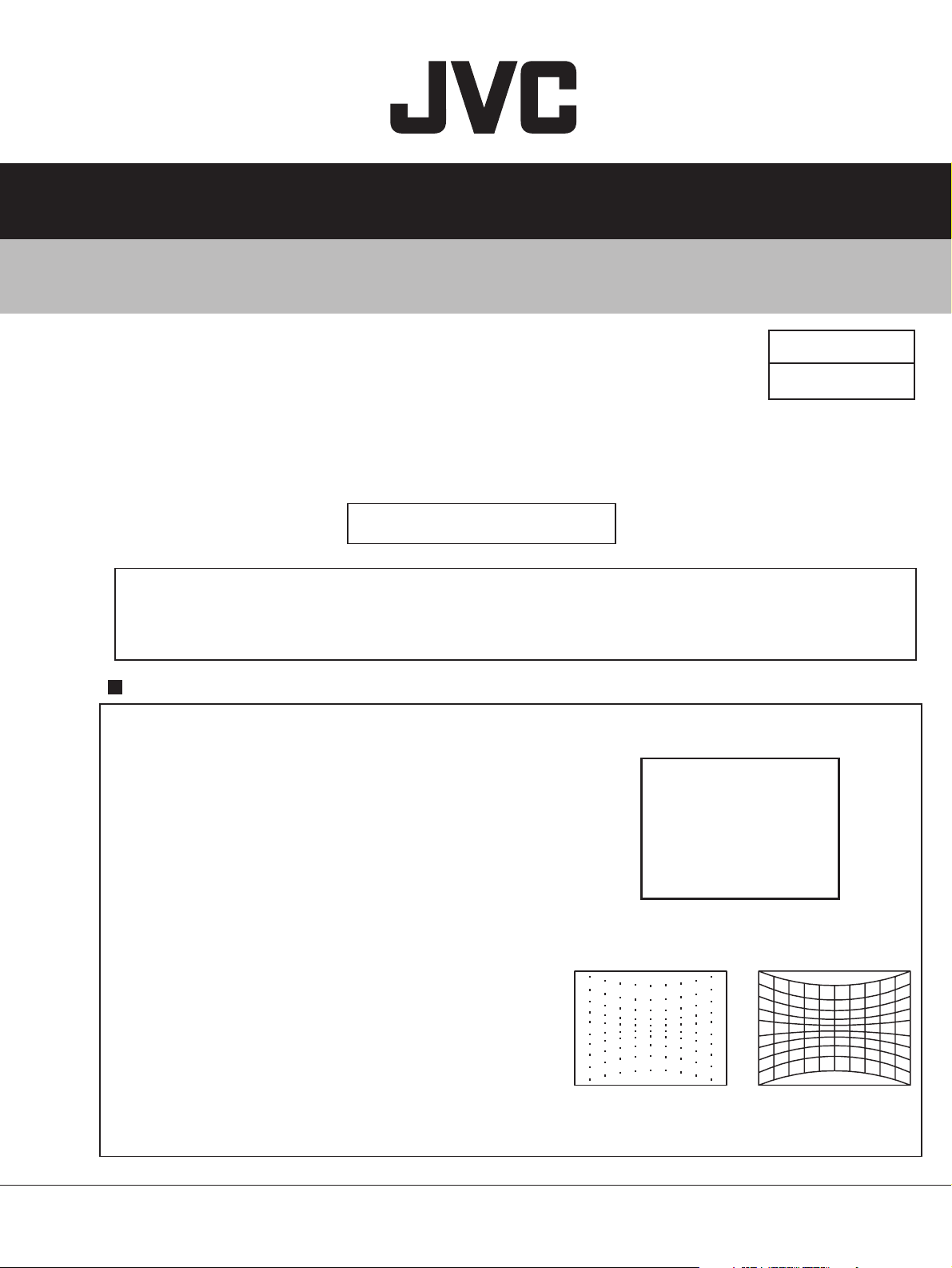
1) HOW TO ENTER TEST MODE
1.
Press [SLEEP TIMER] key and set SLEEP
TIMER 30 MIN.
2.
While the indication of SLEEP TIMER 30
MIN. is being displayed, press [DISPLY] key
and [VIDEO STATUS] key. The TEST
MODE screen is displayed. (Fig. 1)
3. Press [5] key and enter the 5.CONVER OFF.
(Fig. 2)
4. Press [INPUT] key and select the cross-hatch
pattern. (Fig. 3)
NOTE : For this adjustment, it is necessary to use
a remote control unit (e.g. RM-C322G) with
[INPUT] key.
TEST MODE
1. I2C STOP
2. STATUS DISP.
4. SELF-CHK
5. CONVER OFF
ROM CORRECTION : ACT
ROM VERSION :
Fig. 2 Fig. 3
*******
Fig. 1
1
COPYRIGHT © 2003 VICTOR COMPANY OF JAPAN, LTD.
No.52105C
2003/10
Page 2
AV-48WP74
AV-56WP74
CORRECT ITEM
1) 2.9.3 SERVICE ADJUSTMENT ITEM (Page.1-18)
8.PP
Multi-picture adjustment and
ADM001~ADM034 Do not adjust
setting
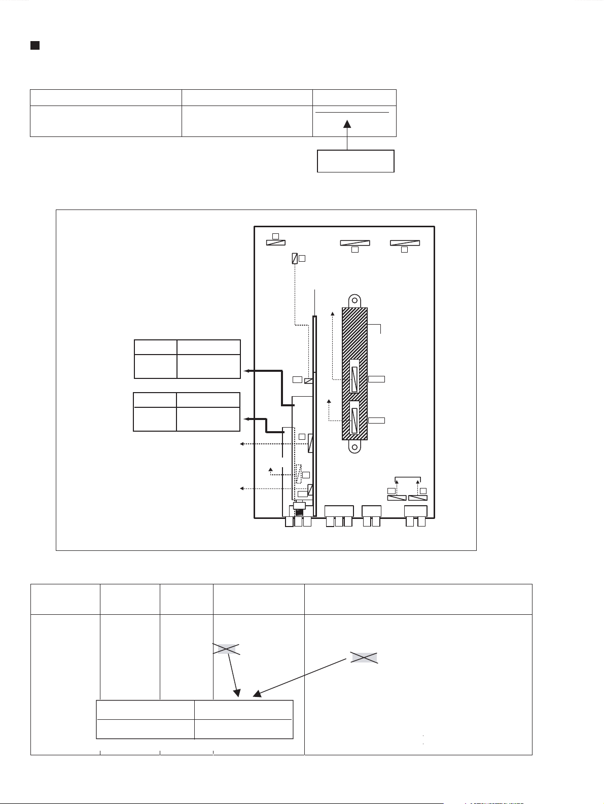
2) 3.4 ADJUSTMENT LOCATION (1/2) (Page.1-22)
MAIN PWB
F
M
RECEIVER
PWB
CONVERGENCE
DELETION
HG
OUT PWB
Incorrect
Correct
Incorrect
Correct
SUB TUNER
(TU101)
MAIN TUNER
(TU0102)
MAIN TUNER
SUB TUNER
(TU1101)
SPEAKER
AUDIO IN
DIGITAL INPUT
MODULE PWB
M
G CRT
SOCKET
PWB
S
DC
S3
AUDIO / VIDEO
S-VIDEO
3) 3.8.2 HORIZONTAL FREQUENCY ADJUSTMENT (Page 1-46)
Item
H. FREQUENCY
adjustment
Measuring
instrument
Signal
generator
Remote
Test point Adjustment part Description
[1.PICTURE/SOUND]
D15 : H. FREQ.
D19 : DEF. RST
control unit
Incorrect <D19>
Correct <D18>
(1) Receive any broadcast.
(2) Press [ASPECT] key and select FULL mode.
(3) Select 1. PICTURE/SOUND from SERVICE MENU.
(4) Select <D19> (DEF. RST) and change the data 0 to 1.
(5) While observing the screen, adjust the <D15> (H.
FREQ) so that an optimum horizontal synchronization is
obtained.
(6) After adjustment, select <D19> and change the data 1
to 0.
(7) Press [MUTING] key to memorize the set value.
MI-COM&DIST
MODULE PWB
CN00Y
CN00E
DIGITAL INPUT
MODULE PWB
SY
COMPONENT
VIDEO-V
Q
AUDIO
(No. 52105C)
2
Page 3
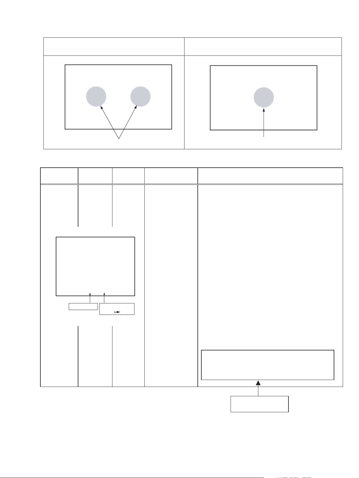
4) 3.8.3 FOCUS & BEAM SPOT ADJUSTMENT (Page 1-47)
Incorrect Correct
CRT FOCUS adjustment point CRT FOCUS adjustment point
5) 3.8.4.2 PREPARATION (Page 1-49)
AV-48WP74
AV-56WP74
Item
SCREEN TILT
adjustment
1.PICTURE/SOUND menu
* * * * * * * *
Measuring
instrument
Signal
generator
Remote
control unit
F62 0
Select item
Test point Adjustment part Description
[1.PICTURE/SOUND]
F62 : Without
convergence 0peration
G DEF. YOKE
R DEF. YOKE
B DEF. YOKE
[PROJECTION UNIT]
Change value
0 1
Confirm correct FOCUS adjustment.
(1) Receive NTSC cross-hatch signal.
(2) Select 1. PICTURE/SOUND from SERVICE MENU.
(3) Select <F62> (Without convergence operation) with [CH +] /
[CH -] key
(4) Change the data 0 to 1, then it makes picture without
convergence operation.
(5) Makes a green single color.
NOTE :
When making a single color, It squeezes SCREEN VR in each
one, or it does a lid to the lens in the adjustment color and it
makes it single color.
(6) Temporarily secure the G deflection yoke to the top of the
neck and adjust the tilt of the deflection yoke so that the
horizontal line at the center becomes flat. After adjustment,
fasten the temporal screw.
(7) Adjust the tilt of the R and B deflection yokes in the same
manner as for green.
NOTE :
Make sure that the adjustment of CRT FOCUS is optimized at the
center and at the fringe of the center in turn. If the proper
adjustment has not been done, adjust FOCUS VR again.
Adjustment according to an internal signal
using TEST MODE is also possible.
(TEST MODE : Refer to top page)
ADDITION
(No. 52105C)
3
Page 4

AV-48WP74
AV-56WP74
6) 3.8.4.2 PREPARATION (Page 1-49)
RASTER
CENTERNG &
H. POSITION /
SIZE (coarse)
adjustment
Signal
generator
Remote
Control unit
R G B
L1
L2
L1=30mm L2=45mm
[1.PICTURE/SOUND]
D03 : H. SIZE
D14 : H. CENTER
F62 : W ithout
convergence 0peration
G CENTERING
magnet
G CENTERING
magnet
G CENTERING
magnet
[DEF. YOKE]
(1) Receive NTSC cross-hatch signal.
(2) Select 1. PICTURE/SOUND from SERVICE MENU.
(3) Select <F62> (Without convergence operation) with [CH
+] / [CH -] keys.
(4) Change the data 0 to 1, then it makes picture without
convergence operation.
(5) Makes a green single color.
NOTE :
When making a single color, It squeezes SCREEN VR
in each one, or it does a lid to the lens in the adjustment
color and it makes it single color.
Select <D03> (H. SIZE) and shorten the level until
(6)
and perpendicular amplitude of vibration with until
the blanking in Left and Right and on either side
can be seen
(7)
Select <D14> (H. CENTER) and adjust horizontal
position to make the screen center and signal
center.
(8) Select <D03> and adjust horizontal size to make
screen picture approx. 92% of H-SIZE.
(9) After adjustment, select <F62> and change the
data 1 to 0.
(10)
Press [MUTING] key and memorize the set value.
(11)
Adjust G CENTERING magnet to make horizontal
and vertical line center as mechanical center of
screen.
(12) Red and blue color too, are reflected by it.
(13) Using R CENTERING magnet and B CENTERING
magnet, adjusts for the line of the red(L1) and the
blue(L2) to become the position of the left figure
NOTE :
Vertical center position of the red and blue are the
same as green.
(No. 52105C)
4
Adjustment according to an internal signal
using TEST MODE is also possible.
(TEST MODE : Refer to top page)
ADDITION
Page 5

7) 3.6.5 SERVICE MENU SETTING (Page 1-26)
3. WHITE BALANCE
Adjustment of LOW LIGHT / HIGH LIGHT
1.SELECT ITEM
• Press [CH+] / [CH-] key
2.SETTING VALUE
BRIGHT
• Press [VOL+] / [VOL-]
DRIVE
[4] key : DRIVE R is up
[7] key : DRIVE R is down
[6] key : DRIVE B is up
[9] key : DRIVE R is down
CUTOFF
[4] key : CUTOFF R is up
[7] key : CUTOFF R is down
[5] key : CUTOFF G is up
[8] key : CUTOFF G is down
[6] key : CUTOFF B is up
[9] key : CUTOFF B is down
3. WHITE BALANCE
AV-48WP74
AV-56WP74
WHITE BALANCE
KEY OPERATION CORRECTION
DRIVE
[2] key : DRIVE R is up
[5] key : DRIVE R is down
[3] key : DRIVE B is up
[6] key : DRIVE B is down
CUTOFF
[7] key : CUTOFF G is up
[100+] key : CUTOFF G is down
[8] key : CUTOFF R is up
[0] key : CUTOFF R is down
[9] key : CUTOFF B is up
[TV] key : CUTOFF B is down
BR
***
DRV R069 B054
CUT R078 G079 B079
R.DRIVE VALUE
B.DRIVE VALUE
B.CUT OFF VALUE
G.CUT OFF VALUE
R.CUT OFF VALUE
(No.52105C) 5
Page 6

AV-48WP74
AV-56WP74
8) 3.8.5 VIDEO ADJUSTMENT
WHITE BLANCE (Page 1-58)
Item
WHITE
BALANCE
(LOW LIGHT)
adjustment
BRIGHT LEVEL
DRIVE
CUTOFF
Measuring
instrument
Signal
generator
Remote
control unit
BR
DRV
SETTING VALUE
NTSC
BR 133
DRV R 073
CUT R 188
480i
BR
DRV R 074
CUT R 194
Test point Adjustment part Description
3. WHITE BALANCE
RRB
GBCUT
B 060
G 149 B 215
B 058
G 149 B 210
[1.PICTURE/SOUND]
S14: CUTOF R
S16: CUTOF G
S18: CUTOF B
S20: CUTOF SW R
S21: CUTOF SW G
S22: CUTOF SW B
ADDITION
Setting value
Incorrect
Correct
[1.PICTURE/SOUND]
S14: CUTOF R
S16: CUTOF G
S18: CUTOF B
S20: CUTOF SW R
S21: CUTOF SW G
S22: CUTOF SW B
[3.WHITE BALANCE]
BR
CUT R
CUT G
CUT B
(1) Receive NTSC black & white pattern signal (color
off).
(2) Select STANDARD mode with [VIDEO STATUS]
key.
(3) The COLOR TEMP is set at the LOW mode.
(4) Select 3.WHITE BALANCE from SERVICE MENU.
(5) Increase bright level to confirm LOW-LIGHT with
[VOL +] key.
(6) Set the setting value.
(7) Adjust using [ 4 ] / [ 7 ] (R CUTOFF), [ 6 ] / [ 9 ] (B
CUTOFF) key so that a black portion may become
black.
(8) Press [MUTING] key and memorize the set values.
(9) Input 480i component black & white pattern signal
from COMPONENT VIDEO terminal.
(10) Repeat steps 5 ~ 8 above.
(11) Input 1080i component black & white signal from
COMPONENT VIDEO terminal.
(12) Repeat steps 5 ~ 8 above.
NOTE :
Before starting the adjustment, warm up the unit for
more than 30 minutes.
REMOTE CONTROL UNIT
OPERATION KEY NO. CORRECTION
R CUTOFF
B CUTOFF
Incorrect
[4] / [7] [8] / [0]
correct
[9] / [TV][4] / [7]
(No. 52105C)
6
1080i
BR
DRV R 074
CUT R 195
REMOTE CONTROL UNIT
123
R CUTOFF
456
R CUTOFF B CUTOFFG CUTOFF
789
B 058
G 149 B 210
EXIT
B CUTOFFG CUTOFF
OSD ON/OFF
0
Incorrect
REMOTE CONTROL UNIT
123
456
789
100+
0
TV
Correct
CUTOFF R
CUTOFF B
Page 7

9) WHITE BALANCE (Page 1-59)
Signal
Measuring
instrument
Test point Adjustment part Description
Signal
generator
Remote
control unit
1. PICTUER/SOUND
NTSC FULL DA H FL MUTE
DRIVE RS10
INITIAL SETTING VALUE
NTSC 480i 1080i
Item
WHITE
BALANCE
(HIGH LIGHT)
adjustment
Setting Item Setting value
Item
S10 073 074 074
S12 060 058 058
***
Setting value
[1.PICTURE/SOUND]
S10: DRIVE R
S12: DRIVE B
ADDITION
AV-48WP74
AV-56WP74
(1) Receive NTSC black & white signal (color off).
(2) Select STANDARD mode with [VIDEO STATUS]
key.
(3) The COLOR TEMP is set at LOW mode.
(4) Select 1.PICTER/SOUND from SERVICE MENU.
(5) Select <S10> (DRIVE R) or <S12> (DRIVE B).
(6) Set the INITIAL SETTING VALUE.
(7)
Adjust <S10> or <S12> so that the natural white
should be visible.
(8) Press [MUTING] key and memorize the set values.
(9) Input 480i component black & white signal from
COMPONENT VIDEO terminal.
(10) Repeat steps 5 ~ 8 above.
(11) Input 1080i component black & white signal from
COMPONENT VIDEO terminal.
(12) Repeat steps 5 ~ 8 above.
(No.52105C) 7
Page 8

JVC SERVICE & ENGINEERING COMPANY OF AMERICA
DIVISION OF JVC AMERICAS CORP.
www.jvcservice.com(US Only)
JVC CANADA INC.
Head office : 21 Finchdene Square Scarborough, Ontario M1X 1A7 (416)293-1311
4
Printed in Japan
200310WPC
 Loading...