

Page 1

A
SER VICE MANUAL
REAR PROJECTION TELEVISION
V-48WP30
BASIC CHASSIS
AV-48WP30
SB2
CONTENTS
SPECIFICATIONS
!
SAFETY PRECAUTIONS
!
FEATURES
!
FUNCTIONS
!
INSTALLATION
!
TECHNICAL INFORMATION
!
1
・・・・・・・・・・・・・・・・・・・・・・・・・・
・・・・・・・・・・・・・・・・・・・・・・・・・・
・・・・・・・・・・・・・・・・・・・・・・・・・・・・・・・・・・・・・・・・・・・・・・・・・・・・
・・・・・・・・・・・・・・・・・・・・
・・・・・・・・・・・・・・・・・・・・
・・・・・・・・・・・・・・・・・・・・・・・・・・・・・・・・・・・・・・・・
・・・・・・・・・・・・・・
・・・・・・・・・・・・・・
・・・・・・・・・・・・・・・・・・・・・・・・・・・・
・・・・・・・・・・・・・・・・・・・・・・・・・
・・・・・・・・・・・・・・・・・・・・・・・・・
・・・・・・・・・・・・・・・・・・・・・・・・・・・・・・・・・・・・・・・・・・・・・・・・・・
・・・・・・・・・・・・・・・・・・・・・・
・・・・・・・・・・・・・・・・・・・・・・
・・・・・・・・・・・・・・・・・・・・・・・・・・・・・・・・・・・・・・・・・・・・
・・・・・・・・・・・・
・・・・・・・・・・・・
・・・・・・・・・・・・・・・・・・・・・・・・
COPYRIGHT © 2002 VICTOR COMPANY OF JAPAN, LTD.
2
3
4
4
7
8
MAIN PARTS LOCATION
!
SPECIFIC SERVICE INSTRUCTIONS
!
SERVICE ADJUSTMENTS
!
TROUBLESHOOTING
!
PARTS LIST
!
★
OPERATING INSTRUCTIONS
★
STANDARD CIRCUIT DIAGRAM
・・・・・・・・・・・・・・・・・・・・・・・
・・・・・・・・・・・・・・・・・・・・・・・
・・・・・・・・・・・・・・・・・・・・・・・・・・・・・・・・・・・・・・・・・・・・・・
・・・・・・・・・・・・・
・・・・・・・・・・・・・
・・・・・・・・・・・・・・・・・・・・・・・・・・
・・・・・・・・・・・・
・・・・・・・・・・・・
・・・・・・・・・・・・・・・・・・・・・・・・
・・・・・・・・・・・・・・・
・・・・・・・・・・・・・・・
・・・・・・・・・・・・・・・・・・・・・・・・・・・・・・
・・・
・・・
・・・・・・
・・・・・・・
・・・・・・・
・・・・・・・・・・・・・・
No.51914
Feb. 2002
9
10
19
51
53
2-1
Page 2
A
V-48WP30
SPECIFICATIONS
Items Contents
Dimensions (W
Mass
TV RF System
Color System
Sound System
TV Receiving Channels and Frequency
VL Band
VH Band
UHF Band
CATV Receiving Channels an d Frequenc y
Low Band
High Band
Mid Band
Super Band
Hyper Ban d
Ultr a B a nd
Sub Mid Band
TV/CATV Total C hannel
Antenna Terminal
Intermediate Frequency
Video IF Carrier
Sound IF Carrier
Color Sub Carrier
Power Input
Power Consumption
Screen
Screen Size
Projection Tube
High Voltage
Speaker
Audio Power Out put
External Input
Audio Output
Digital-Input
Speaker Input
AV Compulink
Remote Control Unit
D)
××××H××××
Video Input
Audio Input
S-Video
Component Input
ⅢⅢⅢⅢ φ
120.0cm×124.4cm×60.9cm ( 47-1/4
81.0 kg (179.0 Ibs)
CCIR (M)
NTSC
BTSC System (Multi Channel Sound)
(02~06) 54MHz~88MHz
(07~13) 174MHz~216MHz
(14~69) 470MHz~806MHz
(02~06, A-8) by (02~06&01)
(07~13) by (07~13)
(A~1) by (14~22)
(J~W) by (23~36)
(W+1~W+28) by (37~64)
(W+29~W+84) by (65~125)
(A8, A4~A1) by (01, 96~99)
180 Channels
75Ω(VHF/UHF) F-type connector
45.75MHz
41.25MHz (4.5MHz)
3.58MHz
120V AC, 60Hz
248W
Transparent screen (unitized fresnel lens / double lenticular lens)
(122cm) Measured diagonally, 16:9 ratio (W:106.3cm, H:59.8cm)
48
17cm (6.7
31kV±1.0kV (at z ero b eam cur r ent )
13cm round×2, φ5.5cm r ound×2
φ
10W+10W
1Vp-p, 7 5Ω (RCA pin jack×4)
500mVrms ( -4dBs ), high impedance (RCA pin jack×8)
Y: 1Vp-p positive (negative sync provided, when terminated with 75Ω)
C: 0.286V
Mini-DIN 4pin connector×2
P
B
P
R
Y: 1Vp-p
1080i DTV (digital broadcast) ready
Fix : 500mVrms(-4dBs) low impedance (1kHz when modulated 100%)
DVI-D signal link 19pin connector
(Digital-input terminal is not compatible with computer signal.)
45W 16Ω(max imum input)
3.5mm m in i jac k
RM-C322G
(AA/R6/UM-3 b atter y×2)
) tube ×3 ( R / G / B )
(burst signal, when terminated with 75Ω)
p-p
: ±0.35Vp-p
: ±0.35Vp-p
,75
Ω
(RCA pin jack×2)
,75
Ω
(RCA pin jack×2)
,75
Ω
(RCA pin jack×2)
24
×49×
(54MHz~804MHz)
)
2
No. 51914
Page 3
A
SAFETY PRECAUTIONS
V-48WP30
1. The design of this product cont ains special hardware, m any
circuits and components specially for safety purposes. For
continued protection, no changes should be made to the
original design unless authorized in writing by the manufacturer.
Replacement parts must be identical to those used in the
original circuits. Service should be performed by qualified
personn el only.
2. Alter ati ons of t h e d esign or circ uitry of th e products s h oul d n o t
be made. Any design alterations or additions will void the
manufacturer's warranty and will further relieve the
manufacturer of responsibility for personal injury or property
damage resulting therefrom.
3. Many electrical and mechanical parts in the products have
special safe ty-related characteristics. These characteristics are
often not evi dent from vis ual insp ecti on nor c an the pr otecti on
afforded by them necessarily be obtained by using
replacement components rated for higher voltage, wattage, etc.
Replacement parts that have these special safety
charact erist ics are identif ied in th e parts lis t of Servic e m anual.
Electric al comp on ent s hav ing su ch f eatur es ar e id ent ifi ed
by shading on the sche m atic s an d by (
in Service manual.
does not have the same safety characteristics as the
recommended replacement part shown in the parts list of
Servi ce m a nua l ma y cause s hock, f i re, or ot her h a zards .
4.
Use isolat i on tra nsformer wh en hot chassis.
The chass is an d any su b-chass is c ontain ed in som e prod ucts
ar e con nect ed t o on e sid e of th e AC p owe r lin e. An is olat ion
transf ormer of adequate cap acity should be ins erted between
the produc t and the AC power supp ly point while perf ormin g
any service on some products when the HOT chassis is
exposed.
5.
Don't short b etween the LIVE s ide gr ound a nd IS OLATE D
(NEUTRAL) side ground or EARTH side ground when
repairing.
Some model's power circuit is partly different in the GND. The
differenc e of the G ND is shown by t he LI VE : (") side GND,
the ISOLATED(N EUTRAL) : (#) sid e GND an d EARTH : ($)
side GND. Don't short between the LIVE side GND and
ISOLATED(NEUTRAL) side GND or EARTH side GND and
never meas ure with a meas uring app aratus (oscill osc ope etc.)
the LIVE side GND and ISOLATED(NEUTRAL) sid e GND or
EARTH side GND at the same time.
If above note will not be kept, a fuse or any parts will be broken.
6. If any repair has been made to the chassis, it is recommended
that the B1 setting should be checked or adjusted (See
ADJUSTMENT OF B1 POWER SUPPLY).
7. The high vol t age applied t o the pictur e tube must conf orm wit h
that specif ied in Service manual. Excessi ve high voltage can
cause an increase in X-Ray emission, arcing and possible
component damage, therefor e operation under excessive high
voltag e conditi ons sh ould b e kept to a mini mum, or shoul d be
prevented. If severe arcing occurs, remove the AC power
immediately and determine the cause by visual inspection
(incorr ect inst allati on, crac ked or melt ed high volt age har ness,
poor sold ering, etc.). T o maint ain the proper minimu m level of
soft X-Ra y emiss ion, comp onents i n the high voltag e circuit ry
includi ng the pic ture tu be must be the exact r eplacem ents or
alternatives approved by the manufacturer of the complete
product.
8. Do not check high voltage by drawing an arc. Use a high
voltag e meter or a high vol t age prob e wit h a VTVM. Disc harg e
the picture tube before attempting meter connection, by
connect ing a c lip lead to t he gr ound fr am e and c onnect ing t h e
other end of the lead through a 10kΩ 2W resistor to the anode
button.
9. When service is required, observe the original lead dress.
Extra pr ecauti on shou ld be gi ven to assure c orrect l ead dr ess
in the high voltage circuit area. Where a short circuit has
occurred, those components that indicate evidence of
overheating should be replaced. Always use the
manufacturer's replacement components.
The use of a substitute replacement which
) on th e parts li st
!!!!
10.
Isolation Check
(Saf ety for Electri cal Shock Hazard )
After r e- assembling t he product, always perf orm an isolation
check on the exposed metal parts of the cabinet (antenna
terminals, video/audio input and output terminals, Control
knobs, metal cabinet, screwheads, earphone jack, control
shafts , etc.) to b e sure th e produc t is saf e to oper ate with out
danger of electric al sh oc k.
(1)
Dielectric Streng th T est
The isolation between the AC primary circuit and all metal parts
exposed to the user, particularly any exposed metal part having
a return path to the chassis should withstand a voltage of
1100V AC (r.m.s.) for a period of one second.
(. . . . Withstand a voltage of 1100V AC (r.m.s.) to an appliance
rated up t o 120V, an d 3000 V AC (r. m.s.) to an ap pli anc e rat ed
200V or mor e, f or a peri od of on e s ec on d.)
This method of test requires test equipment not generally found
in the service trade.
(2)
Leak age Current Check
Plug th e AC lin e c ord dir ec tly into th e AC outl et ( do not us e a
line is olati on transf ormer during this ch ec k .) . Us ing a "L eakage
Current Tester", measure the leakage current from each
exposed metal part of the cabinet, particularly any exposed
metal part having a return path to the chassis, to a known good
earth gr ound ( water pi pe, etc.) . An y l eakage c urrent mus t n ot
exceed 0.5mA AC (r.m.s.).
However, in tropical area, this must not exceed 0.2mA AC
(r.m.s.).
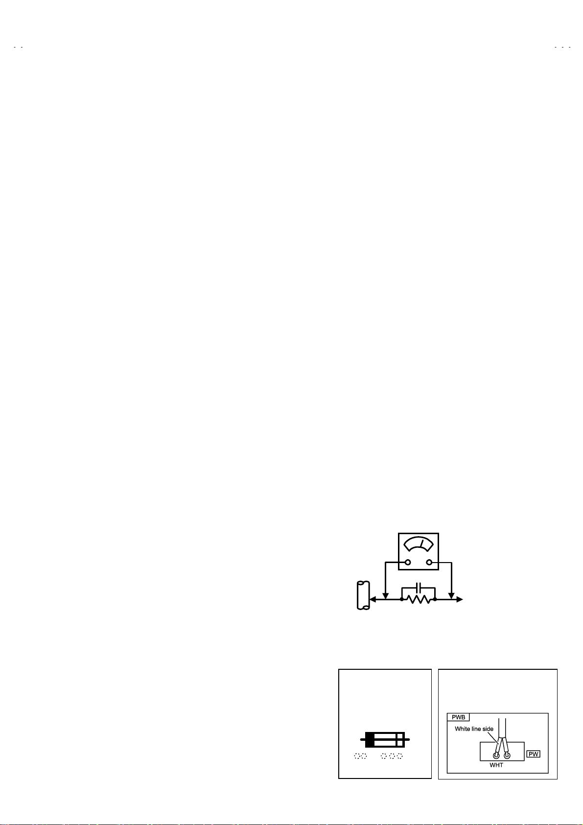
Alternate Check Method
""""
Plug th e AC lin e c ord dir ec tly into th e AC outl et ( do not us e a
line isolation transformer during this check.). Use an AC
voltmeter having 1000 ohms per volt or more sensitivity in the
following manner. Connect a 1500Ω 10W resistor paralleled
by a 0.15μF AC-type capacitor between an exposed metal
part and a known good earth ground (water pipe, etc.).
Measure the AC voltage across the resistor with the AC
voltm eter . Mo ve the resis t or c on n ection to eac h e xp os ed metal
part, particularly any expo se d metal part having a return path to
the chass is, and m easure the AC voltag e across the r esistor.
Now, reverse the plug in the AC outlet and repeat each
measur ement. A ny volt age m easur ed mus t not exc eed 0.75V
AC (r.m.s.). This corresponds to 0.5mA AC (r.m.s.).
However, in tropical area, this must not exceed 0.3V AC
(r.m.s.). This corresponds to 0.2mA AC (r.m.s.).
AC VOLTMETER
(HAVING 1000
GOOD
EARTH
GROUND
11.
High voltage hol d do wn circuit chec k.
After repair of the high voltage hold down circuit, this circuit
shall be checked to operate correctly.
See item "
circuit
This mark shows a fast
operating fuse, the
letters indicat e d be lo w
show the rating.
0.15μF AC-TYPE
1500
10W
Ω
How to check the high voltage hold down
".
OR MORE SENSITIVITY)
PLACE THIS PROBE
ON EACH EXPOSED
METAL PART
POWER CORD
REPLACEMENT WARNING.
Connecting the white line side of power
cord to “WHT” character side.
/V,
Ω
A V
No. 51914
3
Page 4

A
V-48WP30
FEATURES
New chassis d esi gn enable use of an in t er ac ti ve on sc r een control.
"
2-3PULL DOWN : You can enjoy DVD movies at the highest picture quality.
"
MOTION COMPENSATION : With this function, the seamless reproduction of dynamic motion on the screen has been realized.
"
Bullet-in DSD (Digital Supper Detail) circuit and 3 dimension Y/C separate circuit.
"
Receive DTV broadcast (1080i / 720p / 480p / 480i)
"
Built-in HDCP / Component (Y / P
"
Built-in Hyper Sound, BBE circuit.
"
/ PR)
B
FUNCTIONS
■■■■
FRONT CONTROL KEY & T ERMINAL
2
1
■
REAR TERMINAL
MENU Button ( OPERATE
5
4
3
1
Channel -/+ Button ( OPERATE / )
2
VOLUME -/+ Button
3
MAIN POWER SW Button
4
POWER LAMP (BLUE)
5
INPUT4
6
( AUDIO / VIDEO / S-VIDEO )
)
▼
6
1
7
DIGITAL IN
6
5
6
8
10
9
4
3
2
4
No. 51914
1
( DVI-D Signal Link 19pin )
INPUT 1
2
( AUDIO / VIDEO / S- VIDEO )
INPUT 2
3
( AUDIO / VIDEO )
INPUT 3
4
( AUDIO / VIDEO / S- VIDEO )
INPUT 2
5
( COMPONENT VIDEO )
INPUT 3
6
( COMPONENT VIDEO )
SPEAKER INPUT
7
AUDIO OUT
8
AV COMPULINK
9
AUDIO INPUT(For DIGITAL IN)
A
Ⅲ
Page 5

A
■■■■
REMOTE CONTROL UNIT [ RM-C322G ]
3 2
POWER Key
1
ASPECT Key
2
V-48WP30
4
5
6
7
8
17
15
16
18
1
VCR / DVD Key
3
TV / CATV Key
4
NATURAL CINEMA Key
5
INPUT Key
6
DISPLAY Key
7
SLEEP TIMER Key
8
BBE Key
9
V.STATUS Key
A
19
9
10
12
11
20
13
14
21
HYPER SURROUND Key
B
MUTING Key ( memory Key )
C
FUNCTION Key ( ▲ / ▼ /
D
MENU Key
E
MULTI SCREEN Key
F
NUMBERS Key
G
100+ Key
H
/ )
RETURN+ Key
I
22
LIGHT Key
J
V-CHIP Key
K
EXIT Key
L
VCR / DVD Key
M
No. 51914
5
Page 6

A
V-48WP30
■■■■
DIGITAL-IN TERMINAL FUNCTIONS
PIN
No.
1 RX2- 13 RX3+
2RX2+14 5V
3 GND2/ 4 15 GND
4
5 RX4+ 17 RX0-
6 SCL 18 RX0+
7 SDA 19 GND0/5
8NC20RX5-
9 RX1- 21 RX5+
10 RX1+ 22 GNDC
11 GND1/3 23 TXC+
12 RX3- 24 TXC-
PIN NAME
RX4-
PIN
No.
16 HTPLG
PIN NAME
PIN AS SIG NMENT
17
18
19
20
21
22
23
24
9
10
1
2
11
3
12
4
13
5
6
14
7
8
15
16
6
No. 51914
Page 7

A
INSTALLATION
1. INSTALLATION SITE
1. The rear of this s et is provi ded with ventilati on openings . Inst all the set
more than 5 c m from a wall and in a loc at i on w ith good ven t i l ation.
2. Avoid the following types of locations.
(1) U ns table locat i ons (l oc ati on mus t b e abl e to wi ths tand heav y wei ght).
(2) Locatio ns subjected to direct sunlight.
(3) Near sto ves or other heating devic es.
(4) Locations subjected to humidity or oily smoke.
(5) Dusty locations.
(6) Locati ons wi th strong vibration.
2. INSTA LLATION ADJUSTMENT
When installing, moving or changing the orientation of the set, perform
static convergence adjustment according to the following procedure.
V-48WP30
(m ore than 5cm)
Wall
VENTILATION OPENING
1. Press the MENU key of the remote control unit.
2. Select the "CONVERGENCE" in the INITIAL SETUP menu with Function
key.
▲/▼
3. Press the Function / key, the convergence adjustment screen appears
with crosses ( +) displayed in 9 locations.
Locati ons where the cross es appear in 3 colours
Convergence adjustment is required. Perform steps 4 to 5.
Locations where the crosses are white:
The convergence is adjusted correctly.
lf all the crosses are white, no convergence adjustment is needed.
"
4. The locations of the crosses correspond to the positions of the number keys on
the remote control. A box appears around the selected cross.
5. Press the S ELECT but ton to chan ge the col or of th e box to the c olor of the
cross you want to adjust (r ed or blue).
You cannot adjust the green cross.
"
6. Use the / and / buttons to adjust the position of the cross.
To cancel the ad jus tments before complet i ng the pr oc edu re, press t he EXIT
"
button.
7. Press the ENTER button to end the convergence adjustment procedure.
lf you do not us e the TV c ontrols f or roughl y one minut e, the con vergence
"
adjust m ent sc reen autom atically dis app e ar s .
:
Fig.1
Fig.2
No. 51914
7
Page 8
A
V-48WP30
TECHNICAL INFORMATION
■
MAIN MICRO COMPUTER (CPU) FUNCTION
(MIN102H57K)
PIN
№№№№
PIN NAME
1 CONV. SW
2 /VSYNC
3 LB PRO
4 NC
5 /RST
6 CONV. BUSY
7 /TEST
8 YS
9 NC
10 NC
11 A_MUTE
12 /HSYNC
13 M_MUTE
14 OSDXI
15 OSDXO
16 SDA2
17 AC_IN
18 SCL2
19 TU_POW
20 VCOI
21 PDO
22 /IP_RESET
23 YM
24 B
25 LED_POWER
26 G
27 R
28 VREF
29 IP_ERR
30 IREF
31 COMP
32 AVDD
33 CLL
34 VREFLS
35 SUB_CCD
36 NC
37 VSS
38 MAIN_CCD
39 VREFHS
40 CLH
41 VDD
42 LED_DATA
I/O
I/O
I/OI/O
CONVERGENCE SW
OOOO
V.SYNC IN for OSD
IIII
LOW B Protection
IIII
NC
-
Micon Reset input
IIII
CONV.
OOOO
+3.3V
IIII
OSD YS OUT
OOOO
Micon test pin
OOOO
NC
OOOO
TV Sound Muting
OOOO
H.sync input for OSD
IIII
Monitor Out Muting
OOOO
-
-
I2C BUS (SDA) for MTS
OOOO
AC 50/60Hz in
IIII
I2C BUS (SCL) for MTS
OOOO
Tuner Power Control
OOOO
LPF input
IIII
LPF output
OOOO
OOOO
OSD YM out
OOOO
OSD Blue out
OOOO
LED for Power
OOOO
OSD Green Out
OOOO
OSD Red Out
OOOO
IIII
AMDP program load det.
IIII
IIII
IIII
+3.3V
IIII
For Sub CCD
IIII
STD VOL in for Sub CCD
IIII
For Sub CCD
IIII
NC
-
GND
IIII
For main CCD
IIII
STD VOL in for CCD
IIII
For main CCD
IIII
+3.3V
OOOO
Front control Data
OOOO
FUNCTION
PIN
№№№№
PIN NAME
43 LED_CLOCK
44 LED_ON_TIMER
45 SBO0
46 SBD0
47 AP DATA
48 INC
49 ECO RST
50 ROT COIL L
51 ROT COIL R
52 H BLK
53 SN COIL_R
54 SN COIL_L
55 BS POW
56 I2C STOP
57 NC
58 /LOB_POW
59 COMPULINK
60 /POWERGOOD
61 /MECA_ON
62 /MAIN_POW
63 NC
64 /B1 POW
65 C / N
66 X-RAY
67 EE CDS
68 KEY2
69 KEY1
70 SCL1
71 SDA1
72 REMO
73 AP REQ
74 VSS
75 OSC2
76 OSC1
77 VDD
78 SCL0
79 AP CLK
80 SDA0
81 NC
82 NC
83 NC
84 P MUTE
I/O
I/O
I/OI/O
OOOO
OOOO
-
-
-
-
OOOO
OOOO
OOOO
OOOO
OOOO
Ter restr ial Mag net i sm Sensor
OOOO ↑
OOOO
OOOO
-
OOOO
IIII
IIII
IIII
OOOO
-
OOOO
-
IIII
-
IIII
IIII
OOOO
I/O
I/O
I/OI/O
IIII
-
IIII
OOOO
IIII
IIII
OOOO
-
I/O
I/O
I/OI/O
-
-
-
OOOO
FUNCTION
F. LED CLK
LED on tim er
Eco Reset
Picture rotation
Picture rotation
H.BLK
BS pow er control
I2C BUS STOP
LOB power control
AV CompulinkⅢInput
Power Condition Check
Machine SW Interrupt
MAIN POWER CONTROL
NC
B1 POWER CONTROL
X-ray detection
Front Key i nput 2
Front Key i nput 1
I2C BUS (CLK) for E2PROM
I2C BUS (SDA) for E2PROM
Remocon IN
GND
4MHz OSC
4MHz OSC
+3.3V
I2C BUS (CLK) for General
I2C BUS (SDA) for General
NC
Pictur e mu ting
8
No. 51914
Page 9

A
MAIN PARTS LOCATION
■
PWB ASS’Y ARRANGEMENT
The PWB ASS’Y is indicated below.
V-48WP30
MAIN PWB ASS’Y (SSB-1051A-M2)
"
POWER & DEF PWB ASS’Y (SSB-2051A-M2)
"
R CRT SOCKET PWB ASS’Y (SSB-3151A-M2)
"
G CRT SOCKET PWB ASS’Y (SSB-3251A-M2)
"
B CRT SOCKET PWB ASS’Y (SSB-3351A-M2)
"
R VM PWB ASS’Y (SSB-7151A-M2)
"
G VM PWB ASS’Y (SSB-7251A-M2)
"
B VM PWB ASS’Y (SSB-7351A-M2)
"
FRONT CONTROL PWB ASS’Y (SSB0L051A-M2)
"
REMOCON SENSOR PWB ASS’Y (SSB-8051A-M2)
"
FRONT CONTROL ASS’Y
CONVERGENCE PWB ASS’Y (SSB-5051A-M2)
"
CONVERGENCE OSD PWB ASS’Y (SSB0T051A-M2)
"
CENTER SPEAKER PWB ASS’Y (SSB0A051A-M2)
"
DIGITAL CONVERGENCE MODULE PWB ASS’Y
"
LINE FILTER PWB ASS’Y (SSB-9051A-M2)
"
DEF OSC PWB ASS’Y (SSB0H051A-M2)
"
I-P CONVERT MODULE PWB ASS’Y (SSB0D051A-M2)
"
FRONT I/F PWB ASS’Y (SSB0L251A-M2)
"
AV JACK PWB ASS’Y (SSB0J051A-M2)
"
RECEIVER PWB ASS’Y (SSB0R251A-M2)
"
DIGITAL INPUT MODULE PWB ASS’Y (SSB-7851A-M2)
"
REMOCON SENSOR
PWB
(Included in CONVERGENCE PWB)
PROJECTION UNIT
FRONT CONTROL
PWB
DIGITAL
CONVERGENCE
MOULE PWB
CONVERGENCE OSD
PWB
CONVERGENCE
PWB
FRONT I/F
PWB
I-P COVERT MODULE
PWB
LINE FILTER
PWB
AV JACK PWB
RECEIVER PWB
POWER & DEF
PWB
MAIN PWB
CRT SOCKET
PWB (R/G/B)
CENTER SPEAKER
PWB
DEF OSC
PWB
AV TERMANEL BOARD
(This figure is only MAIN UNIT)
VM
PWB (R/G/B)
DIGITAL INPUT
MODULE PWB
No. 51914
9
Page 10
A
V-48WP30
A
A
A
A
SPECIFIC SERVICE INSTRUCTIONS
SCREEN HANDLING CAUTIONS
■■■■
SCREEN STORAGE
Store the SCREEN ASS’Y in a standing position in order to avoid deformation. If the screen is stored horizontally, there is risk of def orming the
screen face.
When necessary to place the SCREEN ASS’Y horizontally, position the screen side upwards and sure to place spacers between the screen and
resting site (floor or stand etc.) to prevent the screen from sagging.
■
SCREEN SURFACE
Since the screen surface is easily scratched or soiled, use ample care when handling.
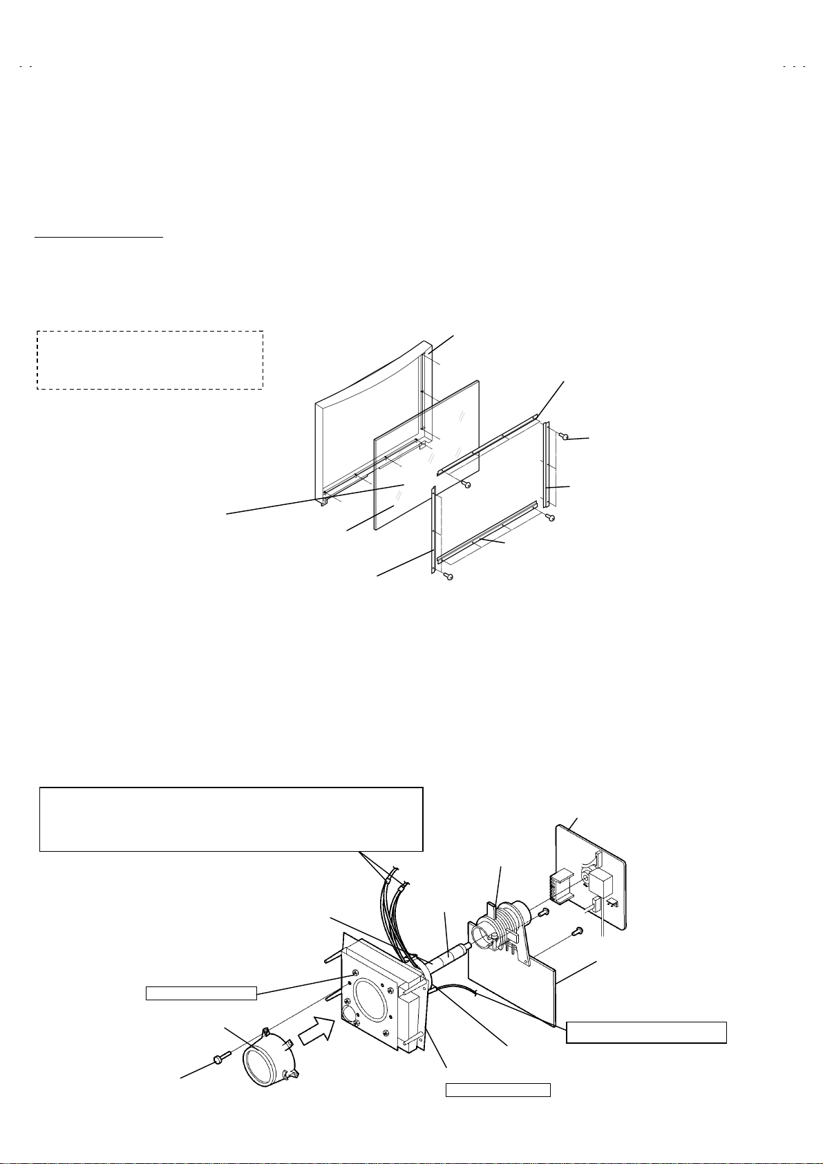
DISASSEMBLY PROCE D URE
%
If the screen or screen panel need to
be replaced, remove the A screws
FRONT CABINET
SCREEN BRACKET (TOP)
(X3)
Leave the screen with flesnel lens and
double lenticular lens attached. If cannot be
disassembled further.
SCREEN
SCREEN BRACKET
(LEFT)
(X4)
SCREEN BRACKET
(BOTTOM)
(X3)
SCREEN BRACKET (RIGHT)
(X4)
PROJECTION UNIT REPLACEMENT
■
ADJUSTMENT DURING REPLACEMENT
When replcing the three R, G and B projection units, first replace the R and B units and perform focus / screen / raster centerin g adjustments
with ref er ence to the G unit. T hen replac e the G unit and perform G foc us / screen / converg ence adjustm ent. Finall y perform R & B .
Convergence adjustments.
■
DISASSEMBLY CAUTION
The projection units include locations that are not to be disassembled during service. When replacing projection unit parts, disassemble to the
state indicated in the figure below.
The figure indicates screws and wires that are not to be removed. Use care not to remove these.
Deflection yoke wires : to connector on POWER & DEF. PWB ASS’Y.
&
[R=”RHV”, G=”GHV”, B=”BHV”]
Convergence yoke wires : to connector on CONVERGENCE PWB ASS’Y
&
[R=”R”, G=”G”, B=”B”]
Use care to simultaneously removes all three-projection units.
R CRT SOCKET PWB ASS’Y
G CRT SOCKET PWB ASS’Y
B CRT SOCKET PWB ASS’Y
PC MAGNET
Check tha t tape is applied to the CRT neck.
If absent, the deflection yoke can dislodge.
Do not remove screws
LENS ASS’Y
LENS ASS’Y SCREW (X 4)
10
No. 51914
PC MAGNET
TAPE
DEF / CONVER. YOKE
CRT ASS’Y(COUPLER ASS’Y)
Do not disassembly
VM PWB PWB (R/G/B)
ANODE wires : to DIVIDER
●
Page 11
A
DISASSEMBLY PROCEDURE
V-48WP30
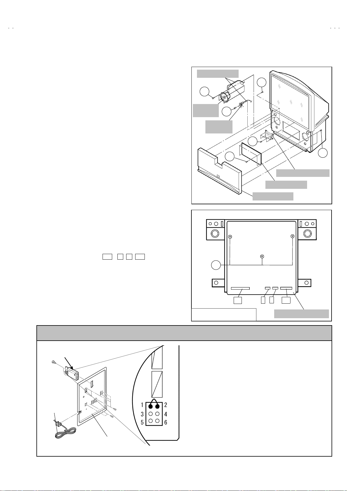
SPEAKER GRILLE
!
1. Remove 4 screws A from rear side.
2. Remove the SPEAKER GRILLE.
SPEAKER (WOOFER)
!
Remove the SPEAKER GRILLE
"
1. Remove 4 screws B.
2. Take out the WOOFER.
3. Disconnect the speaker wire from speaker terminal.
SPEAKER (TWEETER)
!
Remove the SPEAKER GRILLE
"
1. Remove 2 screws C.
2. Take out the TWEETER.
3. Disconnect the speaker wire from speaker terminal.
FRONT BOARD
!
Remove the SPEAKER GRILLE.
"
1. Remove 4 screws D.
2. Remove the FRONT BOARD.
FRONT CONTROL BOX
!
Remove the SPEAKER GRILLE.
"
1. Remove 4 screws E attaching the F RONT CONTROL BOX.
BH
2. Disc onnect the c on nector
CONTROL PWB.
3. Remove the FRONT CONTROL BOX.
, X ,
,
R
on the FRONT
BG
SPEAKER WIRE
B
SPEAKER
(WOOFER)
SPEAKER
(TWEETER)
F
A
C
E
D
FRONT CONTROL BOX
FRONT BOARD
SPEAKER GRILL
A
FRONT CONTROL PWB
!
Remove the SPEAKER GRILLE.
"
Remove the FRONT CONTROL BOX.
"
1. Remove 3 screws F from rear side of FRONT CONTROL BOX.
2. Remove the FRONT CONTROL PWB.
CAUTION AT DISASSEMBLY
48WP30CP-S
: DIGITAL INPUT MODULE
POWER CORD
SB
AV JACK BOARD
connector
BH
FRONT CONTROL BOX
REAR SIDE
X
BG
FRONT CONTROL PWB
R
Prior to disassembly, unplug the power code from the AC outlet
"
without fail. (Turn the power “off”.)
Short the SB connector (1) pin and (2) pin of the DIGITAL
"
INPUT MODULE. (At the time of assembling)
Bef ore the rear panel is i nserted int o the cabi net, releas e the
"
short-cir cuit betw een the SB conn ec tor (1) pin an d (2) pin of the
DIGITAL INPUT MODULE.
After rel easing th e shor t-circ uit bet ween the SB conn ectors, do
"
not turn the power on until the rear p anel is inserted into th e
cabinet.
Negligence in carrying out the above steps may cause the
*
inactivation of the TV.
No. 51914
11
Page 12
A
V-48WP30
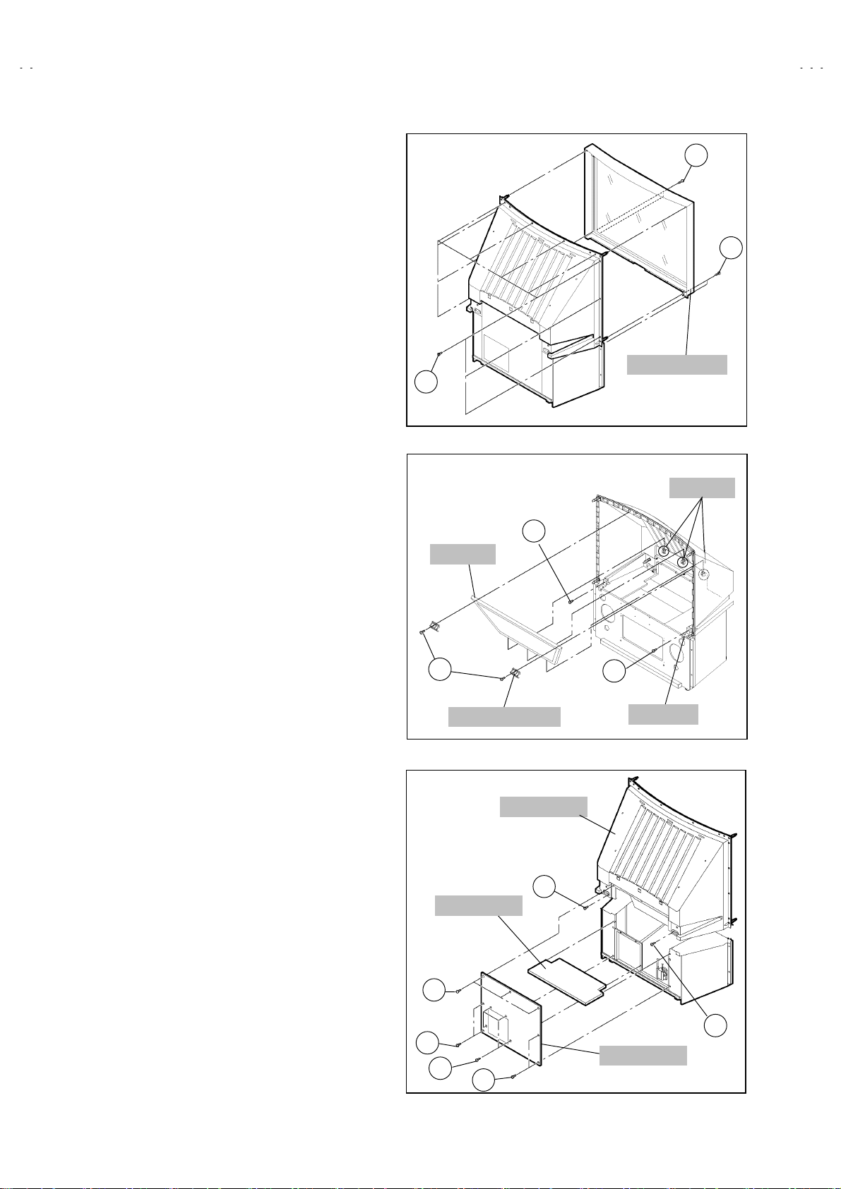
SCREEN ASS’Y
!
Remove the SPEAKER GRILLE.
"
Remove the FRONT CONTROL BOX.
"
1. Remove 4 screws G under the SCREEN ASS’Y from fron t side.
2. Remove 10 screws H from rear side.
3. Remove the SCREEN ASS’Y.
:
NOTE
Place the screen with face upwards on a flat stand.
"
Because of the large size, at least two parsons are
"
recomm en ded for rem ov al an d reas sembl e.
Use core not to scratch the screen during work.
"
Duri ng assembl y, be sur e to eng age the l eft and ri ght tabs
"
with the cabinet mounting positions.
When than s port ing the SC REEN ASS’ Y, avoid gr aspi ng th e
"
top of the screen panel, instead grasp the left and right areas.
MIRROR
!
Remove the SPEAKER GRILLE.
"
Remove the FRONT CONTROL BOX.
"
Remove the SCREEN ASS’Y.
"
1. Remove 2 screws I attaching the mirror stopper.
2. Raise slightly to disengage of the mirror from the hooks.
3. Remove the MIRROR.
:
NOTE
T he M IRROR is front-coated . Do not touch t he front of the
"
MIRROR.
At least 2 persons are recommended for removable and
"
reassemble.
GGGG
GGGG
SCREEN ASS’Y
H
HOOKS
M
MIRROR
REAR PANEL
!
1. Loosen 7 screws
2. Remove 4 screws K.
3. Raise slightly REAR PANEL upward.
4. Remove the REAR PANEL.
:
NOTE
B efor e the rear p anel is ins ert ed in to the c abi n et, rel eas e th e
"
short-cir cuit b etween the S B conn ector ( 1) pin an d (2) pin of
the digital input unit
Af ter releasing t he short-circ uit bet ween the SB c onnectors,
"
do not turn the power on until the rear panel is ins erted into
the cabinet
PA RTITION
!
Remove the REAR PANEL.
"
1. Pull out the PA R T I T IO N back war d.
REAR COVER
!
Remove the SPEAKER GRILLE.
"
Remove the FRONT CONTROL BOX.
"
Remove the SCREEN ASS’Y.
"
1. Remove 2 screws L.
2. Remove 2 screws M from front side
3. Sligh tly pull for back side to di se nga ge of the REAR C OVER from
hooks.
4. Remove the REAR COVER.
J.
I
MIRROR STOPPER
PARTITION
J
J
K
J
M
BRACKET
REAR COVER
L
L
REAR PANEL
12
No. 51914
Page 13
A
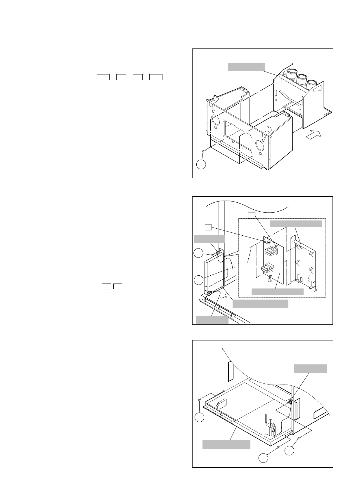
MAIN UNIT
!
Remove the SPEAKER GRILLE.
"
Remove the connector BH
"
FRONT CONTROL PWB.
Remove the REAR PANEL.
"
1. Remove 4 screws
2. Pull out th e MAIN UNIT rear side.
NOTE :
Except for confirmation of projection of images on the screen
"
and audio output thr ough the speakers , the removed main
unit is still workable in the same state as if it is still built in the
TV set. Therefore, the main unit can be removed, if
necessary, for board diagnosis, electric testing, etc. apart
from conf ir m ati on of screen im ag es and audio output.
When wire clamps are removed during work, use care to
"
restore them precisely to their original positions.
Perf ormanc e can be aff ect ed if these ar e not ret urn ed to t he
original positions.
Because of the large size, at least two persons are
"
recomm en ded for rem ov al an d reas sembl e.
W hen carr yin g th e m ain un it, us e c ar e n ot to dr op, s h ock or
"
shake it.
D o not stain or damag e the l ens of the projection unit.
"
Do not look through the projection unit.
"
CHECKING THE P.W. BOARD
#
When checkin g th e M AIN PWB, POWER & DEF PW B, etc., raise
the MAIN UNIT with the DIVIDER side down for the sake of
convenience. You can checking the MAIN P.W.B.
from front side.
O
!
, X , R , BG on the
O
F
EARTH WIRE
P
MAIN UNIT
B
V-48WP30
LINE FILTER BRACKET
LINE FILTER P.W. BOARD
!
Remove the REAR PANEL.
"
Remove the AV JACK BOARD.
"
1. Disconnect the connector
BOARD.
2. Remove 3 sc rews P attach ing th e LI NE F ILTE R BR ACK ET and
earth wir e.
3. Remove 2 screws Q attaching LINE FILTER P.W. BOARD.
4. Remove the LINE FILTER P.W . BOARD.
MAIN CHASSIS
!
Remove the REAR PANEL.
"
Remove the AV JACK BOARD.
"
R emove the LINE FILTER BR ACKET .
"
1. Remove 2 screws R both side of the MAIN CHASSIS.
2. Remove 1 screws
3. Pull out the MAIN CHASSIS for back sid e.
:
NOTE
If necessary, remove the anode wires, connectors,
"
respectively.
R’
B F on the LI NE FILTE R P.W .
attaching the earth wire.
Q
P
LINE FILTER P.W.BOARD
LINE FILTER BRACK ET
EARTH WIRE
EARTH WIRE
R
MAIN CHASSIS
R’
R
No. 51914
13
Page 14
A
V-48WP30
PROJECTION UNIT
!
Remove the SPEAKER GRILLE
"
Remove the FRONT CONTROL BOX
"
Remove the REAR PANEL
"
R emo ve the MAIN UNIT .
"
1. Remove the CRT SOCKET PWB.
2. Remove 4 screws S attaching the PROJECTION UNIT.
3. Pull out the PRO J EC T IO N UNIT, upwar d.
:
NOTE
Refer to “PROJECTION UNIT REPLACEMENT” on
"
page 8 when tak ing out and repl ac ing the PROJE CTION
UNIT.
When wire clamps are removed during work, use care to
"
restore them precisely to their original positions.
Perf orm ance can be affected if th es e are not r etur ned to
the origin al positions .
HV DIVIDER
!
Remove the REAR PANEL
"
1. Remove 1 screws
2. Remove the HV DIVIDER.
Wires of the transformer (FBT) and CRT of each PROJECTION
*
UNIT can be removed by turning the connector portions.
:
NOTE
If nec essary, remove the anod e w ir es, an d replacing the
"
HV DIVIDER, take care to correctly engage the
connector.
U
!!!!
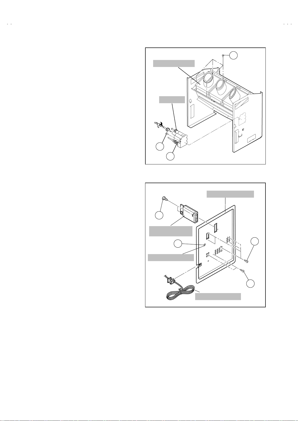
AV JACK BOARD
!
Remove the REAR PANEL
"
1. Remove 7 screws V.
2. Pull out the POWER CORD C LAMP f r om AV J ACK BOARD l eft
side.
3. Remove nut
4. Remove the AV JACK BOARD.
attaching the DIVIDER.
T
!!!!
attaching the antenna terminal.
W
!!!!
PRO J E CTION UN I T
HV DIV IDER
TurnPull
T
U
X
DIGITAL INPUT
MODULE
W
ANTENNA TERMINAL
S
AV JACK BOARD
V
DIGITAL INPUT MODULE
!
Remove the REAR PANEL
"
1. Remove 2 screws X from rear side of the AV JACK BOARD.
2. Remove the DIGITAL INPUT MODULE.
14
V
POWER CORD CLAMP
No. 51914
Page 15
A
REPLACEMENT OF CHIP COMPONENT
CAUTIONS
!
1. Avoid heating for more than 3 seconds.
2. Do not rub the electrodes and the resist parts of the pattern.
3. When removing a chip part, melt the solder adequately.
4. Do not reuse a chip part aft er rem oving it.
SOLDERING IRON
!
1. Use a high ins ul ation sold erin g iron with a thin p oint ed end of it.
2. A 30w soldering iron is recommended for easily removing parts.
REPLACEMEN T STEPS
!
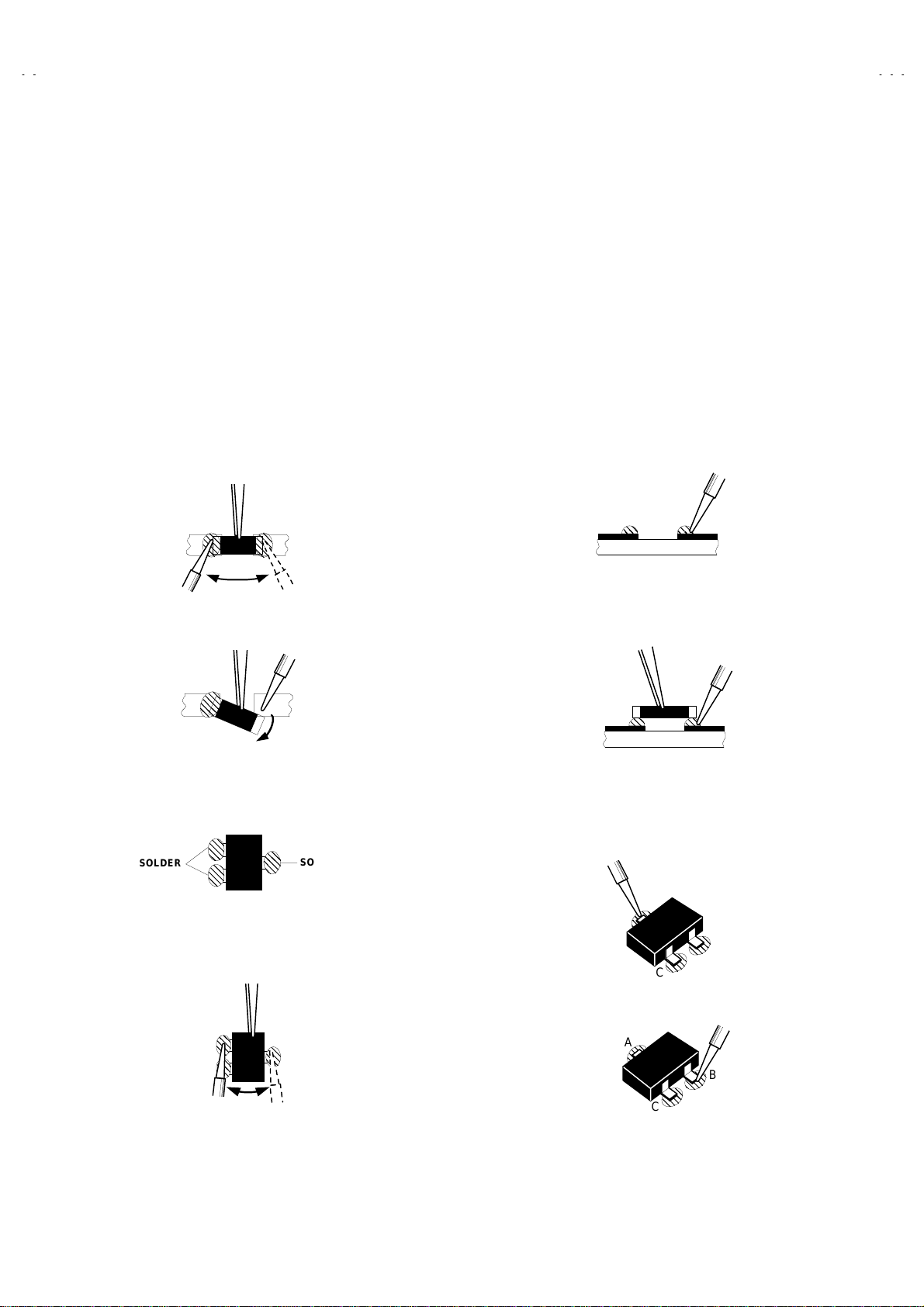
How to remove Chip parts
1.
Resistors, capacitors, etc
####
(1) As shown in the figure, push the part with tweezers and
alternately melt th e s older at each end.
(2) Shif t wi th tweezers an d r em o ve the chip part.
Transistors, diodes, variable resistors, etc
####
(1) Apply extra solder to each lead.
V-48WP30
2. How to i n stal l Ch ip p arts
Resistors, capacitors, etc
####
(1) Apply solder to the pattern as indicated in the figure.
(2) Grasp th e chip part wit h twe ezers and plac e it on t he s older.
Then heat an d m elt t h e s old er at b oth en ds of th e chip part .
Transistors, diodes, variable resistors, etc
####
(1) Apply solder to the pattern as indicated in the figure.
(2) Grasp the chip part with tweezers and place it on the solder.
(3) First solder lead
as indicated in the figure.
A
SOLDER
(2) As shown in the figure, push the part with tweezers and
alternat el y melt t he s old er at each lead . Shif t and r emov e th e
chip part.
Note : After removing the part, remove remaining solder from the
pattern.
SOLDER
No. 51914
A
(4) Then solder leads
A
C
and C.
B
C
B
B
15
Page 16
A
V-48WP30
MEMORY IC REPLACEMENT
1. Memory IC
This model use a memory IC.
This mem ory IC s tores dat a for prop er oper ation of th e vid eo
and deflection circuits.
When rep lacing, be sure to use an IC c ontaining this (i nitial
value) data.
2. Memory IC replacemen t pro cedu re
(1) Power off
Switch off the power and disconn ect the power c ord from
the wall out l et.
(2) Replac e the me mo ry I C
Initial val ue must be ent ered into the new IC .
(3) Power on
Connect the power cord to the wall outlet and switch on the
power.
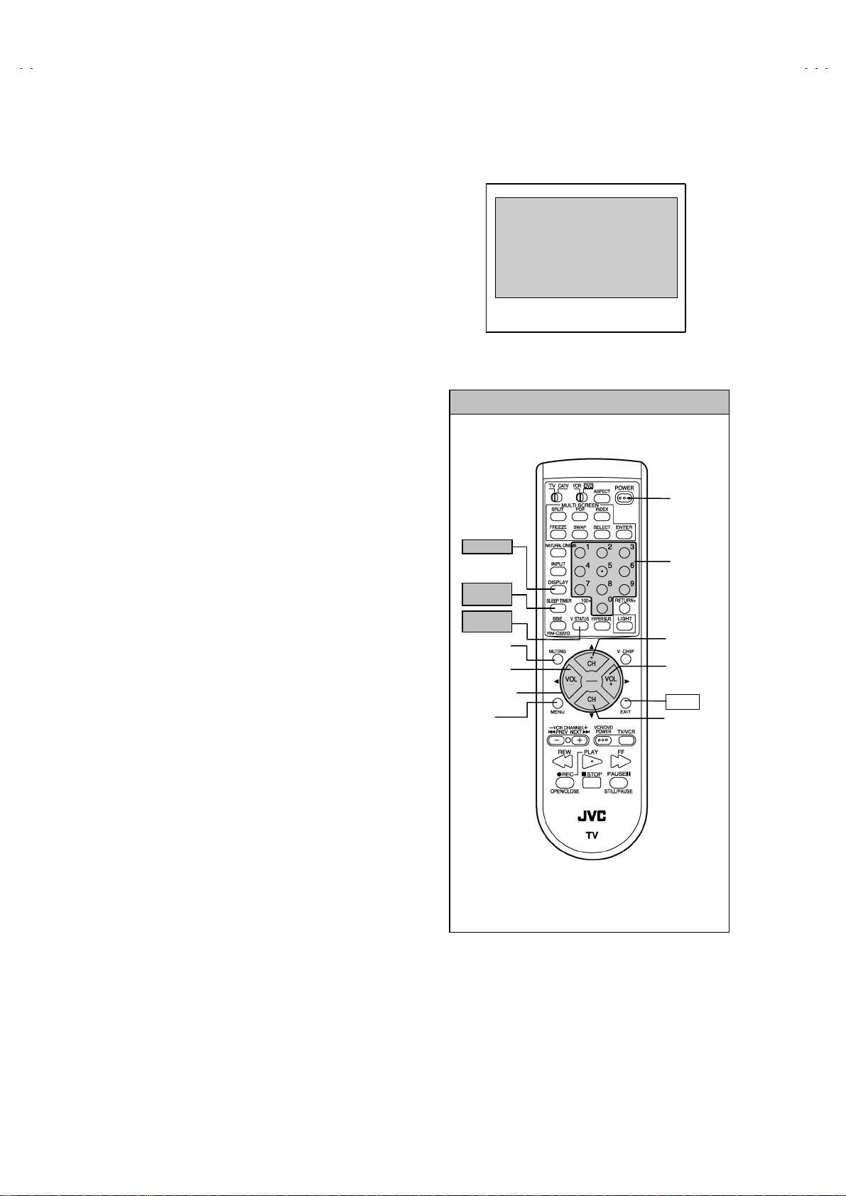
SERVICE MENU
SERVICE MENU
1.PICTURE/SOUND 7.I2C BUS
2.YC SEP 8.PP
3.LOW LIGHT 9.IP
4.HIGH LIGHT 0.SELF-CHK
5.RF AFC
6.
Fig.1
SERVICE MENU SELECT KEY
(4) SERVICE MENU setting
1) Press
SLEEP TIMER
SLEEP TIMER 0 MIN
DISPLAY
key and
key and, while the indication of
is being displayed, press
VIDE O S TAT US
key on the r emote
control unit (Fig.2) simultaneously.
2) The SERVICE MENU screen of Fig.1 is displayed.
3) Verify what to set in the SERVICE MENU, and set
whatever is necessary (Fig.1).
Refer to the SERVICE ADJUSTMENT for setting.
4) Press the EXIT key twice to return normal screen.
(5) Rec eive channel setting
Refer to the OPERATING INSTRUCTIONS (USER’S
GUIDE) and set the receive channels (Channels Preset) as
described.
(6) User settings
Check th e us er s ett ing items according to after page.
Where these do not agree, refer to the OPERATING
INSTRUCTIONS (USER’S GUIDE) and set the items as
described.
DISPLAY
SLEEP
TIMER
VIDEO
STATUS
MEMORY
(MUTING)
VALUE
SELECT(-)
FUNCTION
MENU
POWER
NUMBER
ITEM
SELECT(▲)
VALUE
SELECT(+)
EXIT
ITEM
SELECT(▼)
Fig.2
16
No. 51914
Page 17

A
SHIPPING FACTORY SETTING
VIDEO STATUS MEMORY (NTSC / 480p)
Item
TINT COLOR PICTURE BRIGHT DETAIL
STANDARD 00 00 00 00 00
THATER 00 00 00 00 00
DYNAMIC 00 00 +10 00 +1
(HD)
Item
TINT COLOR PICTURE BRIGHT DETAIL
STANDARD 00 00 00 00 00
THATER 00 00 00 00 00
DYNAMIC 00 00 +2 00 00
CHANNEL SETTING (CHANNEL SUMMARY)
BAND CH Display Setting BAND CH Display Setting
02
○
03 O 28
VHF
L
04
05
06
07
○
○
○
○
08 T 33
VHF
09
H
10 V 35
11
○
○
12 A-7 93
UHF
MID
13
14
36
41 A-3 97
46 A-2 98
63
69
A14
B15
C16
D17
E18
○
○
○
○
○
○
○
○
○
○
F19
G20 W+29
H21
○
I22 W+51
J23
SUPER
K24
L25
○
M26
SETTI NG VALUE
SETTI NG VALUE
SUPER
SUBMID
HYPER
ULTRA
N27
P29
Q30
R31
S32
U34
W36
A-6 394
A-5 95
A-4 96
A-1 99
A-8 01
W+11 47
W+12 48
W+17 53
W+23 59
W+78
W+84
V-48WP30
○
○
○
○
○
○
○
○
○
○
○
No. 51914
17
Page 18

A
V-48WP30
SHIPPING FACTORY SETTING
(USER SETTING)
Setting item Setting value Setting item Setting value
POWER
CHANNEL
BBE
VOLUME
INPUT
OFF
CABLE-02
ON
10
TV
TINT / COLOR / PICTURE
/BRIGHT / DETAIL
COLOR TEMPERATURE
DIG. NOISE CLEAR
Refer to setti n g o f Video
status m em or y at shi pping
factory setting
HIGH
CENTER
DISPLAY
NATURAL CINEMA
SLEEP TIMER
ASPECT
VIDEO STATUS
HYPER SURROUND OFF MTS STEREO
SPLIT SOURCE
POP SOURCE
VERTICAL POSITION
CENTER CH INPUT
XDS ID
CONVERGENCE
POWER INDICATOR
OFF
AUTO
0
REGULAR
DYNAMIC
LEFT SIDE : CH 02
RIGHT SIDE : CH 04
LEFT SIDE : CH 02
RIGHT UPPER : CH 04
RIGHT CENTER : CH 05
RIGH T BOTTOM : CH 07
CENTER
OFF
ON
OPTIMUM CONDITION
HIGH
NOISE MUTING
BASS / TREBLE / BALANCE
SET CLOCK
ON / OFF TIMER
LANGUAGE
CLOSED CAPTION
FRONT PANEL LOCK
AUTO SHUT OFF
AUTO TUNER SET UP
DIGITAL-IN ( at 480p signal
input )
CHANNEL SUMMARY
V-CHIP
SET LOCK CODE
AUTO DEMO
ON
CENTER
Unnece ssary to set
NO
ENG
OFF ( CC1 / T1 )
OFF
OFF
Unnece ssary to set
SIZE 1
Refer to Last memory (CH.
summary)
OFF
Unnece ssary to set
OFF
18
No. 51914
Page 19

A
SERVICE ADJUSTMENTS
V-48WP30
ADJUSTMENT PREPARATION
1. You can make the necessary adjustments for this unit with
either the Remote Control Unit or With the adjustment
tools and parts as give n belo w.
2.
Adjustment with the Remote Control Unit is made on t he
basis of the initial setting values, h owever, the new setting
values wh ich s et t he scree n t o it s op timu m condi tion may
differ from the initial settings.
3. Make sure that AC power is turned on correctly.
4. Turn on t he power for set and test eq uipm ent bef ore us e, and
start the adjustment procedures after waiting at least 30
minutes.
5. Unless otherwise specified, prepare the most suitable reception
or input signal for adjustment.
6. Never touch any adjustment setting value which are not
specified in the list for this adjustment.
7. Preset ti ng b efore adjust m ent
Unless otherwise specified in the adjustment instructions,
preset the following functions with the remote control unit:
ADJUSTMENT EQUIPMENT
1. DC voltmeter (or digital voltmeter)
2. Oscilloscope
3. Signal generator (Pattern generator)
NTSC / 480i / 480p / 720p / 1080i / HDCP
[
4. Remote control unit
5. TV audio multiplex signal generator
6. Frequency counter
ADJUSTMENT ITEMS
Adjustment items
1Check (×4)
2 FOCUS & B EAM SP OT adjustment
3 CONVERG ENCE & DEFL EC TION a dj u stment
4 VIDEO adj us tment
5 MTS adjus t m en t
SETTING POSITION
"
SETTING ITEM SETTING POSITION SETTING ITEM SETTING POSITION
VIDEO STATUS STANDARD ASPECT FULL
BASS, TREBLE, BALANCE CENTER VERTICAL POSITION CENTER
HYPER SURROUND OFF BBE ON
TINT, COLOR, PICTURE,
BRIGHT, DETAIL
COLOR TEMPERATURE HIGH AUTO SHUTOFF OFF
DIGITAL NOISE CLEAR CENTER
CENTER ON/OFF TIMER NO
]
ADJUSTMENT FLOWCHART
WHEN REPLACING SCREEN AND PROJECTION UNIT
Contains only the main adj us tm en t s . Als o c onfirm other adj us tm ents as required.
●
No. 51914
19
Page 20

A
V-48WP30
A
ADJUSTMENT LOCATION (1/2)
CONVERGENCE PWB
IC 805 IC 804
B G R
R/G/B CRT SOCKET PWB
MAIN PWB
FRONT
B
F
LINE FILTER
PWB
S 801
SERVICE
SWITCH
CONVERGENCE OSD PWB
DIGITAL CONVERGENCE
MODULE PWB
F
M
CN00M
CN010
TUNER
(TU101)
CN00Y
CN00P CN00X
FRONT I/F PWB
BG BH
G H
G
RECEIVER
PWB
AJ
DIG I TAL IN PUT PW B
FRONT
CONVERGENCE
OSD PWB
TOP
IC701
CPU
AF
FRONT CONTROL PWB
POWER POWER SW
BG R X BH
H
CN001
MEMORY IC
IC703
CN002
E
CN003
LED
CH - CH + VOL - VOL +MENU
INPUT 3
REMOCON SENSOR PWB
B
POWER/DEF
PWB
P
J
G VM PWB
G CRT SOCKET PWB
CN010
20
1Pin : L
2Pin : R
3Pin : GND
4Pin : SOA
5Pin : NC
POWER CORD
S2
1
5
TUNER
I-P CONVERT.
MODULE
PWB
S2
DIGITAL INPUT
PWB
V
JACK
PWB
DC SY Q2 AJ
CN007
No. 51914
CN006
DEF OSC PWB
S1
Page 21

A
ADJUSTMENT LOCATION (2/2)
REAR
TOP
TOP
MAIN PWB
AV JACK PWB
V-48WP30
DIGITAL INPUT MODULE PWB
DVI-D
terminal
IC
FOCUS PACK
MAIN PWB
DC
Q
SY
SB
CONNECTOR
LINE
FILTER
PWB
H
CRT SOCKET PWB
RGK
TP-E TP-R
KR
R CRT SKT PWB G CRT SKT PWB B CRT SKT PWB
B
CN001
SG001
GBK RGK
TP-E TP-G
E
SG001
KG
POWER / DEF PWB
GBK
SG001
TP-E TP-B
KB
IC701
CPU
5Pin : TP-91(B1)
4Pin : NC
3Pin : X-ray1
2Pin : X-ray2
1Pin : TP-E ( )
MEMORY IC
IC703
S1
5
1
CN002
J
G VM PWB
DEF OSC PWB
E
CN003
CN010
RHV
GHV
AB
S1
5
BHV
FBT
No. 51914
A
1
21
Page 22

A
V-48WP30
(
)
)
BASIC OPERATION OF SERVICE MENU
1.
TOOL OF SERVICE MENU OPERATION
Operate the SERVICE MENU with the REMOTE CONTROL UNIT.
2.
SERVICE MENU ITEMS
In general, basic setting (adjustments) items or verifications are performed in the SERVICE MENU.
1. PICTURE / SOUND
2. YC SEP
・・・・・・・・・・・・・・・・・・・・
3. LOW LIGHT
4. HIGH LIGHT
5. RF AFC
・・・・・・・・・・・・・・・・・・・・
・・・・・・・・・・
・・・・・・・・・・・・・・・・・
・・・・・・・・・・・・・・・・
6. (BLANK)
7. I2C BUS
8. PP
9. IP
0. SELF-CHK
・・・・・・・・・・・・・・・・・・・・
・・・・・・・・・・・・・・・・・・・・・・・・・
・・・・・・・・・・・・・・・・・・・・・・・・・・
・・・・・・・・・・・・・・・・・・
3. BASIC OPERATIO NS OF THE SERVICE MENU
(1) How to enter the SERVICE MENU.
Press
SLEEP TIMER
TIMER 0 MIN.
VIDEO STATUS
to enter th e
SERVICE MENU
(2) SERVICE MENU screen selection
Press th e nu mb er k ey t o sel ec t an y of t h e foll ow i ng items.
1.PICTURE/SOUND 7.I2C BUS
2.YC SEP 8.PP
3.LOW LIGHT 9.IP
4.HIGH LIG HT 0. SELF-CHK
5.RF AFC
key and, whil e the indic ation of “
” is being displayed, press
key on the remote control unit simultaneously
This sets the setting values of the VIDEO/CHROMA /AUDIO and DEFLECTION circuits.
This is used when the YC mode is adjusted.
[Do not adjust]
This sets the setting values of the WHITE BALANCE circuit.
This sets the setting values of the WHITE BALANCE circuit.
This is used when the IF VCO is adjusted.
This is used when ON/OFF if the I
2
[Do not adjust]
C BUS control is stop.
This sets the setting value of the output of P&P data.
This sets the setting value of the IP circuit.
[Do not adjust]
This sets the self checking of the TV circuit.
SLEEP
DISPLAY
key and
screen as sh own in t h e fig. 1.
KEY FUNCTION of SERVICEMENU
[Do not adjust]
SERVICE MENU
1. PICTURE/SOUND
2. YC SEP
3. LOW LIGHT
4. HIGH LIGHT
5. RF AFC
6.
Fig. 1
7. I2C BUS
8. PP
9. IP
0. SELF-CHK
(3) Enter the any setting mode
1. PICTURE / SOUND mode
"
1) S el ec t the 1. PICTURE / SOUND items with the number
key, and the FUNCTION (▲/▼) key is pressed the 1.
PICTUR E / SO U ND mode, the scr een w il l b e dis p layed as
shown in figure page later.
2) Then the sett in gs or verificati ons c an be performed.
2.YC SEP, 3.LOW LIGHT, 4.HIGH LIGHT, 5.RF AFC,
"
2
7.I
C BUS, 8.PP, 9.IP and 0.SELF-CH K mode
1) If you select any of 2.YC SEP 3.LOW LIGHT 4.HIGHLIGHT 5.R F A FC 7 .I
2
C BUS, 8.PP , 9.I P an d 0.SE LF-C HK
mode items, and the numbers key is pressed from
SERVICE MENU, the each screens will be displayed as
shown in figure page later.
2) Then the settings or verifications can be performed.
22
No. 51914
DISPLAY
key
SLEEP TIMER
key
MUT I N G key
MENU key
FUNCTION key
& (
▲/▼
/
NUMBERS
key
VIDEO STATUS
key
EXT key
(PIP OFF)
Select the setting value
Select the setting Item
Page 23

A
V-48WP30
A
Function
/
(
Function
(
▲/▼
) key
) key
SERVICE MENU
SERVICE MENU
1. PICTURE/SOUND
2. YC SEP
3. LOW LIGHT
4. HIGH LIGHT
5. RF AFC
6.
7. I2C BUS
8. PP
9. IP
0. SELF-CHK
1.PICTURE/SOUND
NTSC
***** *****
***** *****
***** ***** ***** *****
A01 001
*** *** ******* ******
*** *** ******* ****** *** *** ******* ******
A01
*** *** *** *****
*** *** *** *****
*** *** *** ***** *** *** *** *****
S01
*********
*********
********* *********
*** *** ******* ******
A16
~~~~
A01
*** **********
*** **********
*** ********** *** **********
S57
~~~~
LOW
4.HIGH LIGHT
HW-BAL
*** ***
*** ***
*** *** *** ***
5.RF AFC
TUNER
AFC
FINE
**
**
** **
**
**
** **
***
***
*** ***
7.I2C BUS
Press th e
0 key → ON/OFF
DO NOT ADJUST
DO NOT ADJUST
YC001
~
~~
~
YC007
S01
*** **********
*** **********
*** ********** *** **********
*** *** **********
*** *** **********
*** *** ********** *** *** **********
D01
D20
~~~~
D01
*** *********
*** *********
*** ********* *** *********
*** *** **** **** *
*** *** **** **** *
*** *** **** **** * *** *** **** **** *
F01
F64
~~~~
F01
*** *********
*** *********
*** ********* *** *********
*** *** ******* **** *
*** *** ******* **** *
*** *** ******* **** * *** *** ******* **** *
2.YC SEP
YC001
********** *
********** *
********** * ********** *
*** *** ******* *** ***
*** *** ******* *** ***
*** *** ******* *** *** *** *** ******* *** ***
3.LOW LIGHT
LW-BAL
*** *** ***
*** *** ***
*** *** *** *** *** ***
I2C
***
***
*** ***
8.PP
PPA001
***
***
*** ***
9.IP
NTSC PIP
IP001 NTSC OFF FRAME 0
*****
*****
***** *****
LOW
0.SELF-CHK
IO
NG2
LOB
OK
SYNC
M:OK
MEM
OK
VCD
NG2
AIO
OK
TUN
OK
PP
NG4
OCP
TIM
S:OK
AVSW
BS
YC
OK
OK
NG2
OK
HD:NG
OK
OK
OK
OK
OK
PPA001
008
~~~~
PPB001
036
~~~~
PPC001
007
~~~~
ADM001
ADS001
VCM001
VCS001
034
~~~~
034
~~~~
038
~~~~
041
~~~~
DO NOT ADJUST
IPA001
120
~~~~
IPB001
088
~~~~
IPC001
044
~~~~
IPD001
058
~~~~
IPE001
015
~~~~
Press the 0 key → ON/OFF
No. 51914
23
Page 24

A
V-48WP30
A
(
y
(▼)
(▼)
(4) Setting method
1) UP / DOWN (▲/▼) FUNCTION key
Select the SETTING ITEM.
2) LEFT / RIGHT ( / ) FUNCTION key
Setting ( ad jus t) th e s ett i ng v al u e of th e SET T IN G ITE M .
When the MU T I NG key is pressed th e setting valu e
will be stored (memorized).
3) EXIT key
Returns to the previous screen.
(5) Releasing SERVICE MENU
1) After returning to the SERVICE MENU upon completion
of the setting work, press the EXIT key again.
SIGNAL
SYSTEM
SPECT
SIZE
**** ***********
**** ***********
**** *********** **** ***********
SETTING A01
ITEM D01
*** *** *** *** ***
*** *** *** *** ***
*** *** *** *** *** *** *** *** *** ***
1.PICTURE/SOUND
NTSC
FULL
DYNAMIC
A001
001
A16 / S01
~~~~
D20 / F01
~~~~
OFF
S57
~~~~
F64
~~~~
2.YC SEP
YC001
***
***
*** ***
FRAME
LOW
WHITE BALANCE
VIDEO STATUS
SETTING VALUE
DO NOT ADJUST
SETTING ITEM
YC001
YC107
~~~~
SETTING VALUE
WHITE BALANCE setting
"
The setting for 3.LOW LIGHT and 4.HIGH LIGHT are described in
the WHITE BALANCE pag e of ADJUSTMENT .
WHITE BALANCE key function
R.CUT OFF
R.DRIVE
R.CUT OFF
R.DRIVE
(▲)
MEMORY
MUTING
MENU ke
FUNCTION key
(▲/▼) & ( / )
Select the setting value
Select the setting Item
G.CUT OFF
G.CUT OFF
B.CUT OFF
B.DRIVE
B.CUT OFF
B.DRIVE
W.BALANCE
SETTING VALUE
(ON or OFF)
EXIT key
(▲)
(▼)
(▲)
WHITE BALANCE
3.LOW LIGHT
LW-BAL
*** *** ***
*** *** ***
*** *** *** *** *** ***
4.HIGH LIGHT
HW-BAL
*** ***
*** ***
*** *** *** ***
5.RF AFC
SETTING ITEM
Setting Value
・・・・
B.CUT OFF VALUE
G.CUT OFF VALUE
R.CUT OFF VALUE
SETTING ITEM
Setting Value
・・・・
B.DRIVE VALUE
Setting Value
・・・・
R.DRIVE VALUE
DO NOT ADJUST
24
NOTE)
TUNER 2
AFC ON
FINE
***
***
******
(
TUNER 1(MAIN)/2(SUB)
AFC Select ON/OFF
FINE Fine Tuning(-77
AFC ON :Aut o Setting
+77)
~~~~
No. 51914
Page 25

A
V-48WP30
X
8.PP
SETTING ITEM
PPA001
PPA008
~~~~
PPB001
PPB036
~~~~
PPC001
PPC007
~~~~
PPA001
***
***
*** ***
ADM001
SETTING VALUE
ADM034
~~~~
8.PP / 9.IP setting
1) FUNCTION(▲/▼) key
2) FUNCTION ( / ) key
3) SLEEP TIMER key
4) MUTING Key
5) EXIT key
・・・・・・・・・・・・・・・・・・・・・・・・・・・・・・・・
・・・・・・・・・・・・・・・・・・・・・・・
・・・・・・・・・・・・・・・・・・・・・・・・・・・・
・・・・・・・・・・・・・・・・・・・・・
・・・・・・・・・・・・・・・・・・・・
Select the setting Item
Select the setting value.
Skip the each setting Item.
Setting value will be stored.
Ret urns to the service menu.
* Press the EXIT key again, then releasing the service menu.
0.SELF-CHK DISPLAY
Press 0 key of remote control that checks the circuit
operating status and in event of malfunction displays
stores the data in memory. (shown in figure)
NTSC PIP
IPA001
RAY
LOB
SYNC
MEM
VCD
AIO
TUN
PP
9.IP
******
******
****** ******
OFF FRAM
***
***
*** ***
0.SELF-CHK
NG
OCP
OK
TIM
M:OK
S:OK
OK
AVSW
NG2
BS
OK
TC
OK
GCR
NG4
IP
NG2
OK
HD:NG
OK
OK
OK
OK
OK
***
***
*** ***
DO NOT ADJUST
SETTING ITEM
IPA001
IPA120
~~~~
IPB001
IPA088
~~~~
IPC001
IPC044
~~~~
IPD001
IPD058
~~~~
IPE001
IPE015
~~~~
SETTING VALUE
No. 51914
25
Page 26

A
V-48WP30
INITIAL SETTING VALUE OF SERVICE MENU
1. Adjustment of the SERVICE MENU is made on the basis of th e in itial setting values; however, the new setting values which set the
screen in its opt imum condition may dif f er fr om t h e init ial setting.
2. Do not change the initial setting values of the setting items NOT LISTED IN ADJUSTMENT.
3. The (*1 or *2)mark ed it ems i n follow in g tab le, it is NO R EQU IRE MENT for adj ustm ent. If valu es h ad ch ange by th e mis si ng, s et the
initial values in the following table.
CAUTION
Never change
the initial setting value any adjustments
except
for those that are designated in the
adjustment proc edur es.
In case where you have made undesignated adjustments by mistake, never press the MUTING key on the
remote contr ol unit.
Whenever you had not pressed the MUTING key , you would be able to recover the initial value by switching
the POWER SW (on/off) key.
1. PICTURE / SOUND
■■■■
SOUND SYSTEM
Item
No.
A01 NOISE DET. 0 / 1 000 A09 5TH MON 0 / 1 000
A02 INPUT LEVEL
A03 FH MONITOR 0 / 1 000 A11 INPUT GAIN 0 / 1 000
A04 STEREO VCO
A05 PILOT CAN 0 / 1 000 A13 BBE BASS
A06 FILTER
A07 LOW SEP
A08 HI SEP
■■■■
DEFLECTION SYSTEM
Item
No.
D01 V.HEIGHT
D02 EW PARABORA
D03 H.WIDTH 0~63 051 D13 ADJUSTMENT 0~15 000
D04 V.S-CORR
D05 V.LINEARITY
D06 V.CENTER
D07 TRAPEZIUM
D08
D09
D10 V.EHT
Item name
Item name
EW CORNER
LOWER
EW CORNER
UPPER
Variable
range
0 ~ 63
0 ~ 63
0 ~ 63
0 ~ 63
0 ~ 63
Variable
range
127
0
~
63
0
~
63
0
~
63
0
~
63
0
~
63
0
~
0
15 008 D18
~
0
15 008 D19
~
7
0
~
Initial settin g
value
027 A10 SAP VCO
035 A12 FIL OFFSET
032 A14 BBE TREBLE
027 A15 BASS
028 A16 TREBLE
Initial settin g
value
027 D11 H EHT
022 D12 EHT GAIN
040 D14 H CENTER
039 D15
023 D16 H. BLK
029 D17 OSD OFFSET
003 D20
Item
No.
Item
No.
HORI FREQ
ADJUSTMENT
COMPULSION
TWIN SCREEN
COMPULSION
DEF RST
OUTPUT
COMPULSION
1080i
Item name
Item name
Variable
range
0 ~ 63
-128 ~ +127
-128 ~ +127
-128 ~ +127
-128 ~ +127
-128 ~ +127
Variable
range
0~7
0~7
0~255
0
255
~
0~255
0~127
0
7000
~
0
1000
/
0
1000
/
Initial settin g
Initial settin g
value
035
000
+007
000
-012
-008
value
001
002
172
141
080
044
26
No. 51914
Page 27

A
■■■■
PICTURE SYSTEM
( NTSC / 480i / 480p )
Item
No.
S01 SUB COLOR 0~127 078 058 078 058 080 062
S02 SUB TINT
(1/2)
Item name
Variable
range
0
127
~
Standard Theater Standard Theater Standard Theater
NTSC 480i 480p
078 069 078 069 070 060
V-48WP30
( 720p / 1080i / HDCP )
Item
No.
S01 SUB COLOR 0~127 065 060 070 069 059 058
S02 SUB TINT
( NTSC / 480i )
Item
No.
S03
S04
S05
S06
( 480p / 720p / 1080i / HDCP )
Item
No.
S03
S04
S05
S06
Item name
Item name
SUB BRIGHT 0~255
SUB CONTRAST 0~127
SUB BRIGHT
OFFSET
SUB CONTRAST
OFFSET
Item name
SUB BRIGHT 0~255
SUB CONTRAST 0~127
SUB BRIGHT
OFFSET
CUB CONTRAST
OFFSET
Variable
range
127
0
~
Variable
range
-128~127
-128~127
Variable
range
-128~127
-128~127
720p / 1080i HDCP
Standard Theater
078 063 070 074 070 066
NTSC 480i
Standard Theater Standard Theater
134 133 134 133
079 045 079 045
----
----
480p / 720p / 1080i HDCP SPLIT / FREEZE
Standard Theater Standard Theater Standard Theater
132 134
082 047
--
--
Standard Theater Standard Theater
480p 1080i / 720p
----
----
000 000 000 000
000 000 -010 000
(2/2)
(1/2)
(2/2)
( NTSC / 480i / 480p / 720p / 1080i / HDCP )
Item
No.
S07
S08
S09
Item name
B-Y
DEMODURATION
R-Y
DEMODULATION
G-Y MATRIX SW
Variable
range
0~63 005 002 005 002 020 048 011 020
0~7 007 000 007 000 007 000 003 000
0~3 001 003 001 003 003 003 002 003
NTSC 480i 480p 720p / 1080i / HDCP
Standard Theater Standard Theater Standard Theater Standard Theater
No. 51914
27
Page 28

A
V-48WP30
( NTSC / 480i)
Item
No.
S10
S11
S12
S13
( 480p / 720p / 1080i )
Item
No.
S10
S11
S12
S13
( HDCP )
Item
No.
S10
S11
S12
S13
(1/3)
Item name
R DRIVE 0~255
R DRIVE OFFSET -128~+127
B DRIVE
B DRIVE OFFSET -128~+127
Item name
R DRIVE 0~255
R DRIVE OFFSET
B DRIVE 0~255
B DRIVE OFFSET -128~+127
(3/3)
Item name
R DRIVE
R DRIVE OFFSET -128~+127
B DRIVE 0~255
B DRIVE OFFSET
Variable
range
Standard Theater Standard Theater
High Low High Low High Low High Low
NTSC 480i
-
080
---
080
--
+003 000 000 +008 +003 000 000 +008
0~255
-
074
---
074
-
000
+006 000 000 -025 +060 000 000 -025
(2/3)
Variable
range
-128~+127
Variable
range
0~255
-128~+127
Standard Theater Standard Theater
High Low High Low High Low High Low
--- --
000 000 000 000 +004 000 000 +007
-- ---
000 000 000 000 +006 000 000 -008
Standard Theater
High Low High Low
----
+004 000 000 +005
-- --
+005 000 -010 -023
480p 720p / 1080i
145
150
HDCP
--
--
( NTSC / 480i / 480p / 720p / 1080i )
Item
No.
S14
S15
S16
S17
S18
S19
S20
S21
Item name
R CUT OFF 0~255
R CUT OFF
OFFSET
G CUT OFF 0~255
G CUT OFF
OFFSET
B CUT OFF 0~255
B CUT OFF
OFFSET
R CUT OFF SW 0~3
B CUT OFF SW 0~3
Variable
range
-128~+127
-128~127
-128~+127
NTSC 480i 480p / 720p / 1080i HDCP
Standard Theater Standard Theater Standard Theater Standard Theater
211
-
211
-
215
---
000 +003 000 +003 000 -001 000 +007
050
-
050
-
050
---
000 000 000 000 000 000 000 000
052
-
052
-
059
---
000 +004 000 +004 000 -003 000 +005
000
001
-
-
000
001
-
-
000
001
---
---
28
No. 51914
Page 29

A
( NTSC / 480i / OTHERS SIGNAL)
Item
No.
S22
S23
S24
S25
S26
S27
Item name
BLACK GRAD CORR
START LEVEL
BLACK GRAD CORR
GAIN
WHITE GRAD CORR
START LEVEL
WHITE GRAD CORR
GAIN
WHITE CHARA CORR
START LEVEL
WHITE CHARA CORR
GAIN
Variable
range
0~15
0~15
0~15
0~15
0~15
0~15
NTSC 480i
OTHERS
SIGNAL
015 015 015
008 008 008
000 000 000
015 015 015
002 002 000
000 000 000
V-48WP30
Item
No.
S28
S29
S30
S31
S32
S33
S34
( NTSC / 480i / 480p / 720p / 1080i / HDCP )
Item
No.
S35
Item
No.
S36
Item name
ABL GAIN
ABC START
ACL GAIN
ACL START
CONTRAST LINK 0 / 1
BLACK GRADIATION
CORRECTION OFF
WHITE GRADIATION
CORRECTION OFF
Item name
TINT HD / NTSC 0 / 1
Item name
ABL OFF 0 / 1
Variable
range
0~15
0~15
0~15
0~15
Variable
range
Variable
range
0 / 1
0 / 1
Standard Theater
015 015
015 008
015 000
000 015
000 000
000 001
000 001
NTSC / 480i 480p 720p / 1080i
480p 720p / 1080i
HDCP
001 001 001 001 001
Standard Theater
000 000
ACL OFF 0 / 1
S37
DC TRANSMIT
S38
POLARITY
DC TRANSMIT CORR 0 / 1
S39
BLAKING ON / OFF 0 / 1
S40
( NTSC / 480i / OTHERS )
Item
No.
S41
Item
No.
S42
Item name
DC REPRODUCE
RATE
Item name
ACL CONTROL 0~255
0 / 1
Variable
range
0~255
Variable
range
Standard Theater Standard Theater Standard Theater
000 000
001 000
000 000
000 000
NTSC 480i OTHERS SIGNAL
160 140 160 140 160 72
SPLIT Regular Theater
OTHERS
SIGNAL
160 072 072 072
No. 51914
29
Page 30

A
V-48WP30
Item
No.
S43
S44
S45
( NTSC / 480i / OTHERS )
Item
No.
S46
S47
( ALL SIGNAL )
Item name
CONTRAST
LOWER LIMIT
CONTRAST
UPPER LIMIT
BRIGHT LOWER
LIMIT
Item name
EE THEATER
BRIGHT
EE THEATER
CONTRAST
Item
No.
S48
S49
S50
S51
S52
BRIGHT EE CONT. CORRECTION
REFRAIN EE
CONT. CORRECTION
REFRAIN EE BRIGH OFFSET
CORR (MAX)
BRIGHT EE ACL CORR. COEFF. 0~255
REFRAIN EE ACL CORR. COEFF. 0~255
Item name
Variable
range
-128~+127
-128~+127
-128~+127
Variable
range
-128~+127
-128~+127
Setting Value
Standard Theater
-070 -127
+017 +127
-020 -127
NTSC 480i
000 000 000
000 000 000
Variable
range
0~31
0~31
0~127
Setting
value
008
027
004
085
140
OTHERS
SIGNAL
S53
S54
S55
S56
S57
No use 0 / 1
No use 0 / 1
No use 0 / 1
No use 0 / 1
No use 0 / 1
000
000
000
000
000
30
No. 51914
Page 31

A
V-48WP30
(
p)
(
)
■■■■
OTHERS
Item
No.
F01 EEPROM Ver 1 0~255 051 F32 DIRECT SELECT 2 PIC. 0 / 1 000
F02 EEPROM Ver 2 0~255 001 F33
F03 H.LINE ON (BRIGHT) 0~255 133 F34
F04 H.LINE OFF (BRIGHT) 0~255 140 F35
F05 H.LINE CONTRAST 0~127 000 F36
F06 C38 / C41 SW 0 / 1 001 F37
F07 MODEL SELECT 0~255 000 F38
F08 F39 VSM SHIPPING MODE 0 / 1 000
F09 AUTO SCROLL ADJUST 1 0~15 002 F40 DVD 0~3000
F10 AUTO SCROLL ADJUST 2 0~15 004 F41
F11 AUTO SCROLL ADJUST 3 0~15 004 F42
F12 AUTO SCROLL ADJUST 4 0~15 005 F43 POWER OFF WHITE 0 / 1 000
Item name
Variable
Range
Setting
Value
Item
No.
Item name
CAPTION OSD
OSCSELECT
4 PIC.
HIGH SPEED SEARCH
4 PIC.
AGC REFLESH
4 PIC. HIGH SPEED
WAIT 1
4 PIC. HIGH SPEED
WAIT 2
4 PIC. HIGH SPEED
WAIT 3
2 PICTURE
16:9 MODE
V/C DECODE
H.MASK SETTING
Variable
Range
0~7002
0~255 040
0~255 000
0~255 040
0~255 020
0~255 040
0 / 1 000
0 / 3 000
Setting
Value
F13 AUTO SCROLL ADJUST 5 0~15 006 F44 WHITE BACK ON/OFF 0 / 1 000
F14 AUTO SCROLL ADJUST 6 0~15 007 F45
F15 AUTO SCROLL ADJUST 7 0~15 007 F46
F16 Not use 0 / 1 000 F47
F17 Not use 0 / 1 000 F48
F18 Not use 0 / 1 000 F49
F19 Not use 0 / 1 000 F53 S / N (RF) CORR.WIDTH 0~255 000
F20 Not use 0 / 1 000 F54 S / N (RF) CORR.START 0~255 000
F21 Not use 0 / 1 000 F55 S / N (BS) CORR.WIDTH 0~255 000
F22 Not use 0 / 1 000 F56 S / N (BS) CORR.START 0~255 000
F23 Not use 0 / 1 000 F57
V-CHIP ON/OFF (CANADA)
F24
EARTH MAGNETIC
F25
CORR. PICTURE
OSD OFFSET
F26
F27
F28
F29
F30 PIP 2 PICTURE 0 / 1 000 F64
F31 V.CHIP ON OFF 0 / 1 001
480p / 720p) (HDCP / 480
OSD OFFSET
1080i / HDCP1080i
CH.PROGRAM
SEARCH CYCLE
PIP FUNCTION
ON / OFF
0 / 1 000 F58
0~127 127 F59 S / N (S) CORR.WIDTH 0~255 000
0~63 033 F60 S / N (S) START 0~255 000
0~63 018 F61 OCD OFFSET (HORI.) 0~127 048
0~255 011 F62 ATT GAIN 0 / 1 000
0 / 1 000 F63 V.HEIGHT OFFSET -128~+127 000
S / N (COMP.)
CORR.WIDTH
S / N (COMP.)
CORR.START
TEXT MODE
CONT.CORR.
0~255 000
0~255 000
-128~+127 000
No. 51914
31
Page 32

A
V-48WP30
SIZE 2
Setting Value
Setting Value
HDCP720p HDCP1080i
Item
No.
F50 SEP.LEVEL 0~3 000 002 002 002 002
F51 CLAMP PLUS 0 / 1 000 000 000 000 000
F52 HD PHASE
Item
No.
F50 SEP.LEVEL
F51 CLAMP PLUS 0 / 1 000 000 000 000
F52 HD PHASE
Item name
Item name
Variable
Range
0~63
Variable
Range
0~3
0~63
NTSC 480i 480p 1080i 720p
038 035 026 039 024
HDCP 480p
SIZE 1
002 002 002 002
042 017 047 044
HDCP 480p
(1/2)
(2/2)
32
No. 51914
Page 33

A
ADJUSTMENT
CHECK ITEMS
Item
B1
POWER SUPPLY
check
Signal generator
DC Vol tmet e r
Measuring
Instrument
Test point Adjustment Item Description
S1 connector
5 pin:TP-91
1 pin:TP-E
(
#
)
1. Rec eive a bl ac k and whit e sig n al (c ol or off).
2. C onnect the DC volt meter to S1 conn ector 5 pi n (TP-
91) and TP-E(
3. Confirm that the voltage is DC140V±2V.
) (S1 connector 1 pin).
####
V-48WP30
HIGH VOLTAGE
check
X-RAY
PROTECTOR
check
H.FREQUENCY
check
Signal generator
High Voltage
meter
Resistor
6.8k
1/6W
ΩΩΩΩ
5%
±±±±
Signal
generator
Remote
control unit
CRT Anode
S1 connector
2 pin:X-Ray2
3 pin:X-Ray1
D15 : H.FREQ.
D19 : DEF.RST
1. Rec eive a w hi t e blac k sig nal.
2. Connect the high voltage meter between CRT anode
and GND.
3. Check that the High Voltage DC 31.0kV ±1.0kV.
1. Connect resistor 6.8kΩ(1/6W, ±5%) betw een
2. 2 pin & 3 pin of the connector S1.
3. Confirm that the X-RAY protector functions operated.
1. Receive th e black & whit e sig n al.
2. Preset from 0 to 1 for D19<DEF RST>, to adjust D15:
H.FREQ. and memori z e data with MUT ING key.
3. After adj ustment, to preset fr om 1 to 0 for D1 9: DEF
RST an d Press the MUTING key to memorize data.
No. 51914
33
Page 34

A
V-48WP30
FOCUS & BEAM SPOT ADJUSTMENT
Item
FOCUS &
BEAM SPOT
adjustment
LENS FOCUS
SCREW
PROJECTION UNIT & LENS ASS’Y
( CRT adjustment location )
Measuring
instrument
Signal
generator
Similar
adhesive
(Securing
adhesive)
DEFLECTION
YOKE
CENTERING
4 POLE
MAGNET
CRT FOCUS adjustment point
Test point Adjustment part Description
1. Receive a cross-hatch signal.
2. Press the ASPECT and select the FULL mode.
3. If the pictur e ti lted, adjus t th e R, G an d B D Y posit ion t o m ark
straight horizontal line.
LENS FOCUS
!
4. Makes a red single color.
: When mak ing a sing le col or, It squ eezes SC REEN VR in
NOTE
each one, or it does a lid to the lens in of the adjustm ent
color and it makes it single color.
5. By turning the LENS FOCUS screw (in LENS ass’y), for
optimum focus at the screen center. Check for absence of
difference in the peripheral focus. If the peripheral focus is
poor, slig htly shif t the cent er focus t o obtain overall b alanced
focus.
6. In the sam e mann er, p roduc e gr een and b lue si ngl e c olor and
adjust their respective focus.
7. After adj us tm en t , it fixes a scr ew.
: There is not a differenc e in th e focus i n the top and th e
NOTE
bottom, on either side, in the diagonal.
When the dif ference of the f ocus is bi g, it r em oves a main
lens, and it puts a was her b etwe en the m ain lens and t h e
coupl er and it ad jus t s it.
BEAM SPOT
!
8. Receive a d ot p at t ern signal.
9. Makes a red single color.
: When mak ing a sing le col or, It squ eezes SC REEN VR in
NOTE
each on e, or it does a lid to the lens in of the adjust ment
color and it makes it single c olor.
10. Turn the R FOCUS VR to set the dot diameter to about
30mm.
11. T urn th e 4 pole mag net of t he proj ecti on unit CRT n eck and t o
where the dots at the screen center are nearly circular.
12. Return the R FOCUS VR to its original position (just focus).
13. Turn the 2 pole magnet of the CRT neck to minimize expansion
of the dots.
14. Receive a crosshatch signal.
15. Adjust the overall screen focus.
16. In the same mann er , adj us t f or th e gre en and blue single color.
focus.
17. Secure the 4 and 2 pol e m agnets with similar adh esi v e.
CRT FOCUS
!
18. Receive a crosshatch signal.
19. Makes a red single color.
: When mak ing a sing le col or, It squ eezes SC REEN VR in
NOTE
each one, or it does a lid to the lens in of the adjustm ent
color and it makes it single color.
20. Adjust the R FOCUS VR for optimum focus at the position
indicated in the figure.
21. In the same m anner, adj us t for the gre en and bl u e si n gl e color
focus.
22. After adjustment, return the SCREEN VRs to their original
positions.
:
NOTE
When moving screen VR, always return to original.
MAGNET
2 POLE
MAGNET
G Def. Yoke (DY)
R Def. Yoke (DY)
B Def. Yoke (DY)
[Projection unit ]
R LENS FOCUS
screw
G LENS FOCUS
screw
B LENS FOCUS
screw
[Projection unit
(LENS ASS’Y)]
R SCREEN VR
G SCREEN VR
B SCREEN VR
[FOCUS PACK]
4 pole magnet
2 pole magnet
[Projection unit
(CRT neck)]
R FOCUS VR
G FOCUS VR
B FOCUS VR
[FOCUS PACK]
φ
34
No. 51914
Page 35

A
CONVERGENCE & DEFLECTION ADJUSTMENT
V
(
)
The adjustment using the remote control unit is made on the basis of the initial setting values.
"
The setting values which adjust the screen to the optimum condition can be different from the initial setting values.
"
At first the adjust ment i n FULL mode sh ould b e done, t hen th e data for the other ASPECT mod e is corre cted in t he res pectiv e
"
value at the same time.
FLOWCHART OF ADJUSTMENT
V-48WP30
All adjustments of the DEF circuit for this model should be carried out under the status without convergence operation.
To enter th e st atus w ith ou t c on ver g ence operati on t ur n the power on whil e pressing th e s ervice switch
As a result, you can get the screen as shown in Fig.1. Adjust the DEF circuit in order of the steps indicated by the downward arrows.
Note: When every adjustment of the DEF circuit has completed, start the adjustment of convergence.
CAUTION
on the CONVERGENCE PWB.
S801
PREP ARATION
DEFLECTION
Without
convergence
operation
SCREEN
TILT
RASTER
CENTERING
&
H.POSITION
/ SIZE
coarse
H.SIZE
SIDE PIN
TRAPEZIUM
CONVERGENCE
.PISITION
/ SIZE
/ LINEARITY
H.POSITION
Fig.1
No. 51914
CONVERGENCE
PHASE
OVERALL
CONVERGENCE
35
Page 36

A
V-48WP30
Item
SCREEN TILT
adjustment
CONVERGENCE
PWB
SERVICE SW
(S801)
[CONVERGENCE PWB]
Measuring
instrument
Signal
generator
Test point Adjustment part Description
SERVICE SW
(S801)
[CONVERGENCE
PWB]
G DEF. YOKE
R DEF. YOKE
B DEF. YOKE
[PROJECTION UNIT]
Confirm correct FOCUS adjustment.
!
1. It pushes a power switch while pushing SERVICE SW
the CONVERGENCE PWB then it makes picture without
conver g ence operati on.
2. Receive a cross-hatch signal.
3. Makes a gr een sin gl e c ol or.
: W hen making a s ingle col or, It squ eezes SCR EEN
NOTE
VR in each one, or it does a lid to the lens in the
adjustment color and it makes it single color.
4. Temporarily sec ure the G deflecti on yoke to the top of the neck
and adjus t the ti lt of the defl ection yoke s o th at th e horiz ontal
line at t he center becomes flat. Aft er adjustment, fasten the
temporal screw.
5. Adjust the tilt of the R and B deflection yokes in the same
manner as for green.
: Make sur e that the adjustment of CRT FOCUS is
NOTE
optimi z ed at the center and at th e f rin ge of the center
in turn. If the pr oper ad justm ent has n ot be en don e,
adjust FO CU S VR again.
S801
on
RASTER
CENTERING &
H.POSITION /
SIZE (coarse)
adjustment
Signal
generator
Remote
control unit
SERVICE SW
(S801)
[CONVERGENCE
PWB]
G CENTERING
magnet
R CENTERING
magnet
B CENTERING
magnet
[D EF. YOKE]
D03 : H-SIZE
D14 : H-CENTER
1. It pushes a pow er switch whi le pushi ng SERVIC E SW
the CONVERGENCE PWB then it makes picture without
conver g ence operati on.
2. Receive a circle & cross-hatch signal.
3. Makes a gr een sin gle color.
: When mak i ng a si ngle col or, it s queezes SCREEN V R
NOTE
in each one, or it does a lid to the lens in the
adjustment color and it makes it single color.
4. Select 1.PICTURE/SOUND from SERVICE MENU.
5. Select D03<H-SIZE>and shorten the level until and
perpendicular amplitude of vibration with until the blanking in
Left and Right and on either side can be seen.
6. Select D14<H-CENTER>and adj ust H-CENT ER to m ake the
screen center and signal center.
7. Select D 03<H-SIZE>and adjust H-SIZE to make screen
picture ap prox. 92% of H-S I ZE .
8. Press the MUTING key on the remote control unit and
memori z ed all data.
9. Adjust the G CENTERING magnet to make horizontal and
vertical line center as mechanical center of screen.
10. Red and blue col or , t oo, ar e r efl ect ed by it.
11. Using R CENTERING magnet and B CENTERING magnet,
adjusts for the line of the red and the blue to become the
position of the left figure.
S801
on
L1=30mm L2=30mm
36
No. 51914
Page 37

A
DEFLECTION CIRCUIT ADJUSTMENT
V-48WP30
Item
V. POSITION
/ SIZE
/ LINEARITY
adjustment
H. POSITION
adjustment
Measuring
instrument
Signal
generator
Remote
control unit
C
Test point Adjustment part Descri ption
D01 : V. SIZE
D05 : V. LINEARITY
D06 : V. CENTER
SERVICE SW
(S801)
[CONVERGENCE
PWB]
A
B
D14 : H-CENTER
1. It pushes a power switch while pushing SERVICE SW
the CONVERGENCE PWB then it makes picture without
conver g ence operati on.
2. Set the FULL mode.
3. Receive a c irc le pattern sig nal.
4. Select 1.PICTURE/SOUND from the SERVICE MENU.
5. Select D01<V SIZE >, D05<V LINEARIT Y>,
D06<V CENTER> with the FUNCTION (▲/▼) key.
6. Adjust D06, D0 2 to mak e
to make
C = 45mm
7. Press the MUTING key and memorize the set value.
: To memorize every time after finish adjustment on
NOTE
each mod e. D o n ot adjus t D 04<V. S-CORRECTION
If it is diff er ent V positi on after adjus t V l in earity, t o
>
adjust V position.
8. Select D14<H-CENTER> with FUNCTION (▲/▼) key.
9. Adjust D14 with FUNCTION ( / ) key and make
as shown figure.
10. Press the MUTING key and memorize the set value.
(precis ion ± 2mm), and adjust
A = B
D = E
S801
on
DE
H. SIZE
adjustment
D03 : H-SIZE
Screen size
(92%)
Pictu re size
100%
No. 51914
11. Receive a cross-hatch signal.
12. Select D03<H-SIZE> with the FUNCTION (▲/▼) key.
13. A djus t D03 an d m ake sur e t hat th e vertic al s cr een siz e of th e
picture size is 92%.
14. Press the MUTING key and memorize the set value.
37
Page 38

A
V-48WP30
Item
SIDE PIN
adjustment
TRAPEZIUM
adjustment
Measuring
instrument
Test point Adjustment part De s cription
D02: EW PARABOLA
D08: EW CORNER
LOWER
D09: EW CORNER
UPPER
Straight
D07: TRAPEZIUM
11. S elect D02<EW PARABOLA>, D08<EW CORNER LOW ER>,
D09<EW CORNER UPPER> with FUNCTION (▲/▼) key
respectively.
16. Adjust D02, D08, D09 with FUNCTION ( / ) key and
make th e vertical lines at the left and right ed g es of th e sc reen
straight.
17. Press the MUTING key and memorize the set value.
18. Select D07<TRAPEZIUM> with the FUNCTION (▲/▼) key.
19. Adjust D07 with ( / ) key and bring the vertic al lines at the
right and left edges of the screen parallel.
20. Press the MUTING key and memorize the set value.
Parallel
38
No. 51914
Page 39

A
CONVERG ENCE A D JUST MENT
y
V-48WP30
Item
CONVERGENCE PHASE
Measuring
instrument
Signal
generator
Test point Adjustment part Descri ption
adjustment
Remote
control unit
Dynamic adjustment mode Phase adjustment mode
A
A
Fig. 1
Dynamic adjustment mode
Phase adjustment mode
B
Fig. 3 Fig. 4
REMOTE CONTROL KEY POSITION
SPLIT key
PHASE/DYNAMIC
SERVICE SW (S801)
[CONVERGENCE
PWB]
A
Fig. 2
B
B
1. Press the S ER VICE SW
on the CONVERGEN CE PWB
S801
to enter th e dyn am ic ad jus t m ent m od e.
2. Press the 100+ key on t he remote c ontrol u nit to s elect th e
green lin e.
3. Using the FUNCTI ON (▲) (CH+) key, intentionally expand the
blinkin g h orizontal gr een line as shown in th e
Fig. 1
.
4. Press the SPLIT key on the remote contr ol unit to enter the
phase ad jus t m ent m ode.
5. Using the FUNCTION ( / ) key, adjust the screen so that the
point “A” is loc ated b etween th e cr oss-poi nt of th e dotted l ine
and the vertical line on t h e left si d e as sh ow n in the
Fig. 2
.
6. Press the SPLIT key again to return to the dynamic adjustment
mode.
7. Press the 100+ key on t he remote c ontrol u nit to s elect th e
green lin e.
8. R eturn the p oint “A”, which was intentionally expanded, to its
original position.
9. Using the FUNCTION ( ) key, intentionally expand the
vertical line as shown in the
Fig. 3
.
10. Press the SPLIT k ey t o ent er t h e ph as e adjustm ent m od e.
11. Using the FUNCTION (▲/▼) key, adjust the screen so that the
peak of th e point “B” meets with the adjacent d otted line as
shown in the
Fig. 4
.
12. Press the SPLIT key again to return to the dynamic adjustment
mode.
13. Press the 100+ key to select the vertical green line. Then,
using the FUNCTION ( ) key, return the p oint “B”, which was
intentionally expanded, to its original position.
14. Press the SPLIT key again to enter the phase adjustment
mode.
15. U s ing th e 2/5/4/6 key, adj us t the scr een s o th at th e cr oss -p oin t
of the dotted line is positioned at the scr een center on the
screen. (
Fig. 5
)
16. Press the MUTING key and memorize the set value.
Number key
Screen center
adjustment
100+ key
Select green line
Screen center
MUTING key
Store
FUNCTION ke
Adjusting the line
Fig. 5
No. 51914
39
Page 40

A
V-48WP30
Item
OVERALL
CONVERGENCE
adjustment
Horizontal flashing line
REMOTE CONTROL KEY POSITION
Measuring
instrument
Signal
generator
Remote
control unit
Test point Adjustment part Description
SERVICE SW
(S801)
[CONVERGENCE
PWB]
1. Receive a NTSC sign al.
2. Press the SERVICE SW
S801
3. Appear the flashing cross-hatch pattern.
4. Press the 10 0+ key on t he remot e c ontr ol unit to s elec t green
color.
5. Press MENU key to let green cross-hatch pattern to appear on
screen.
6. Us ing the 2(u p) / 4(left) / 5(down) / 6(right ) of remot e contr ol
key, move the flashing line.
7. Using the FUNCT ION (▲/▼),( / ) key, adjust the position
on the scr een as sh ow n in Fi g.1.
8. Sometime pr ess IND EX key to do int erpol ation pr ocess. Aft er
finishing the adjustment press SELECT key twice to memorize.
9. Press 0 key on the remote control unit to select red color.
10. Repeat steps 5~8.
11. Press RETURN+ key on the remote control unit to s elect blue
color.
12. Repeat steps 5~8.
13. When the adjus t m ent h as b een c ompl eted, press th e MUTING
Vertical flashing line
key and st or e th e dat a on the memor y.
14. Press 0 keys on the remote control unit five times and it
Fig.1
chang es a screen to the 7×5 adjus tm en t point mode.
15. Repeat steps 4~13.
16. Pr ess RETURN+ keys on the remote control unit five times
and it changes a screen to the 13×7 adjust m ent p oint mode.
17. Repeat steps 4~13.
18. Press the SERVICE SW
S801
on the CONVERGENCE PWB.
again.
100+ key
Select green color
0 key
Select red color or
7×5 adjustment
point mode
MUTING key
Store
MENU key
Cross hatch
color change
INDEX key
Interpolation process
SELECT key
ROM write
Number
2 / 4 / 5 / 6 key
Movement of the
flashing line
RETURN+ key
Select blue color or
13×7 adjustment
point mode
FUNCTION
/ / key
▲/▼
Adjusting the line
40
No. 51914
Page 41

A
VIDEO ADJUSTMENT
V-48WP30
Item
A-D C O N V E R TER
OFFSET
adjustment
Measuring
Instrument
Signal
generator
Remote
control unit
GBK RGK
TP-E
CRT SOCKET PWB
Test point Adjustment Item Description
KG
[G CRT
SOCKET PWB]
KB
[B CRT
SOCKET PWB]
KR
[R CRT
SOCKET PWB]
ADM013:
ADM012:
ADM014:
G OFFSET
R OFFSET
B OFFSET
Select the STANDARD mode f or the VIDEO STATUS.
*
1. Receive a whole black (0%) signal.
2. Select REGULAR mode of ASPECT mode.
3. Select that COLOR TEMP in set at the LOW mode.
4. Connect the oscill oscop e to KG (G c athode) on th e G
CRT SOCKET PWB.
5. Select 8.PP from the SERVICE MENU.
6. Select ADM013<G OFFSET>.
7. Adj ust ADM01 3 as 0% sig n al an d out s i d e fr om ar e s et
to same values.
8. Conn ect the oscillosc ope to KB (B cath ode) on the B
CRT SOCKET PWB
9. Select ADM014<B OFFSET>.
E
10. Adjust ADM014<B OFFSET> as 0% signal and
outside from are set to same valu es.
KG / KB / KR
CRT cathode
11. C onnect the osc illosc ope to KR (R cathod e) on th e R
CRT SOCKET PWB
12. Select ADM012<R OFFSET>.
13. Adjust ADM012<R OFFSET> as 0% signal and
outside from are set to same valu es.
14. Press the MUTING key to memorize.
15. Af ter adjustmen t, data of ADM 012, ADM0 13, ADM014
are used to adj us tment of oth er sig n al.
RGB CUTOFF
adjustment
Signal
generator
Oscilloscope
GBK RGK
TP-E
CRT SOCKET PWB
TP-R
[R CRT
SOCKET PWB]
TP-G
[G CRT
SOCKET PWB]
TP-B
[B CRT
SOCKET PWB]
E
S14: R CUTOFF
S16: G CUTOFF
S18: B CUTO FF
TP-R
TP-G
TP-B
Select the STANDARD mode f or the VIDEO STATUS.
*
1. Receive half color bar signal (include -3%).
2. Select that COLOR TEMP in set at the LOW mode.
3. Connect the oscilloscope to TP-G.
4. Adjust S16<G CUTOFF> to mach -3% DC level to
180V.
5. Press the MUTING key to memorize.
: Adjusti ng S16, chang e t he only up. If DC l evel
NOTE
is low at the initial value of CUTOFF, adjust
S03 (brightness).
6. Input 1080i black level pattern signal and input the
value adjusted at NTSC to S16<G CUTOFF>.
7. Press the MUTING key to memorize.
8. Inp ut 480i black l ev el p attern sig n al and input the value
adjust ed at NT SC t o S1 6<G CUTOFF>.
9. Press the MUTING key to memorize.
10. In case of TP-R, TP-B, repeat step 4.~6 above.
If the value of S14 or S18 is max or min, change S20<R
CUTOFF SW>, S21<B CUTOFF SW> and then
adjust S14, S18.
11. Adjus t each R / G / B screen VR on the FO C US P A CK ,
and glimmer +3% point of each R / G / B on the screen.
No. 51914
41
Page 42

A
V-48WP30
Item
WHITE
BALANCE
(Low Light)
adjustment
Setting
item
R. CUTOFF
setting
value
Measuring
Instrument
Signal
generator
Remote
control unit
LOW-BAL
LOW-BAL
LOW-BALLOW-BAL
(***) (***) (***)
G. cutoff
setting value
Press 0 key then appear
Test point Adjustment Item De s cription
S14 : R CUTOFF
S16 : G CUTOFF
S18 : B CUTOFF
S20 : R CUTOFF
SW
S21 : B CUTOFF
SW
B. cutoff
setting value
Select the STANDARD mode ( all “000”) for the VIDEO
*
STATUS.
1. Receive the NTSC blac k and w hite p att ern sign al (c olor
off).
2. Select that COLOR TEMP is set at the LOW mode.
3. Set the initi al setti ng val ues of t he white b alanc e (S14,
S16, S18, S20, & S 21 of Low Light) on the SERVICE
MENU.
4. Select the 3.LOW LIGHT mode from the SERVICE
MENU.
5. Press the 0 key, then setting values appear.
6. In crease the bright level to confirm low-light with
FUNCTION key ( ).
7. Adjust low-light white balance with 4/7(R CUTOFF),
6/9 (B CUTOFF) key of numbe r key.
8. Press the MUTING key for memorize.
9. Receive th e 1080i blac k an d white patter n si gn al.
10. Repeat steps 5.~8. abov e.
11. Receive the 48 0i bl ac k and w hi t e sig nal.
12. Repeat steps 5.~8. abov e.
REMOTE CONTROL UNIT
EXIT
1 2 3
R CUTOFF B CUTOFF
G CUTOFF
4 5 6
G CUTOFF
B CUTOFFR CUTOFF
7 8 9
OSD ON/OFF
0
Setting item
S14 211 211 215
S16 050 050 050
S18 052 052 059
S20 000 000 000
S21 001 001 001
NTSC 480i 1080i
Setting value
42
No. 51914
Page 43

A
V-48WP30
Item
WHITE
BALANCE
(High Light)
adjustment
Setting
ITEM
G DRIVE
setting
value
Measuring
Instrument
Signal generator
Remote
control unit
HW-BAL
*** ***
Fig.1
Press 0 key then appear.
Test point Adjustment Item Description
S10 : R DRIVE
S12 : B DRIVE
R DRIVE
setting
value
Select the STANDARD mode (all "000") on the VIDEO
*
STATUS.
1. Receive th e NT S C black and whit e si gnal (color of f ) .
2. Select that COLOR TEMP is set at the LOW mode.
3. Select the 4.HIGH-LIGHT, and set the initial setting
values of the WH IT E BALANCE (S10 & S12 of HIGH
LIGHT) on th e SER VICE MENU.
4. Press the 0 key, then setting values appear.
5. Make sure that the WHITE BALANCE tracking from the
LOW-LIGHT through the HIGH-LIGHT has been
properly done. (When the black and white signal
(color off) is received, the natural white should be
visible.)
6. Input the 1080i which an d bl ac k signal.
7. Repeat steps 3.~5. abov e.
8. Input the 480i black an d white signal .
9. Repeat steps 3.~5. abov e.
10. Press the MUTING key and memorize the set values.
INITIAL SETTING VALUE
Item
S10 080 080 078
S12 074 074 070
Setting value (STANDARD LOW)
NTSC 480i 1080i
REMOTE CONTRO L UNIT
EXIT
1 2 3
R DRIVE B DRIVE
4 5 6
B DRIVER DRIVE
7 8 9
OSD ON / OFF
0
Fig.2
No. 51914
43
Page 44

A
V-48WP30
Item
SPLIT
WHITE BALANCE
(High Light)
adjustment
Measuring
Instrument
Signal
generator
Remote
control unit
TWIN PICTURE
MAIN
picture
(LEFT) (RIGHT)
Fig.1
Test point Adjustment Item Description
ADS012 :
R OFFSET
ADS014 :
B OFFSET
1. Select SPLIT mode.
2. Receive the NTS C bl ac k & wh it e sig nal both the
picture.
3. At firs t to adj ust AD S0 12
B OFFSET>, next to adj ust th e whit e level on right
<
picture s am e as l eft screen (Fig. 1).
4. Press the MUTING key and memorize the set values.
SUB
picture
R OFFSET> and ADS014
<
Item
SUB BR I GHT
adjustment
S03:SUB BRIG HT
Signal
Item
Setting
value
STANDARD THEATER STANDARD THEATER STANDARD THEATER
Measuring
Instrument
Remote
Test point Adjustment Item Description
S03 : SUB BRIGHT
control unit
INITIAL SETTING VALUE
NTSC 480i 1080i
134 133 134 133 132 134
Table1
1. Receive the NTS C bl ac k & wh it e sig nal.
2. Select 1.PICTURE/SOUND from SERVICE MENU.
3. Select S03<SUB BRIGHT> with FUNCTION (
▲/▼
key.
4. Set the initial setting value with the FUNCTION ( / )
key. (Table1)
5. Adjust S03, not to flash part of black on the screen.
6. Press the MUTING key and memorize the set values.
7. Select THEATER / LOW white balance, and then
repeat steps 3~7 above.
8. Rec eive 108 0i blac k an d whi te an d s elect ST AND ARD
/ LOW, and then repeat steps 3~7 above.
9. Receive 1080i black and white signal and select
THEAT ER / LOW mode, and then repeat steps 3~7
above.
10. Input 480i black and white signal, and select
STAND ARD / LOW mode, and t hen r ep eat s teps 3~7
above.
11. And then select THEATER / LOW mode, repeat steps 3
7 above.
~
)
44
No. 51914
Page 45

A
V-48WP30
Item
SUB CONTRAST
adjustment
S04:SUB CONTRAST
Signal
Item
Setting
value
STANDARD THEATER STANDARD THEATER STANDARD THEATER
078 045 079 045 082 047
Measuring
Instrument
Remote
control unit
INITIAL SETTING VALUE
NTSC 480i 1080i
Table2
Test point Adjustment Item Description
S04 : SUB CONT.
1. Receive the NTS C bl ac k & wh it e sig nal.
2. Enter the SERVICE MENU of 1.PICTURE/SOUND
Item.
3. Select S04<SUB CONT> with FUNCTION (
key.
4. Set the Initial setting value with FUNCTION ( / ) key.
(Table2)
5. If the contrast is not the best with the initial setting value,
mak e fin e adjus tme nt of th e S04<SUB CONT.> until
you get the optimum contrast.
6. Press the MUTING key and memorize the set values.
7. Select THEATER / LOW.
8. Receive the 1080i black and white signal and then
repeat steps 3~7 above.
9. Inp ut the 480p black an d white signal and then rep eat
steps 3~7 above.
▲/▼
)
Item
SPLIT
SUB BR I GHT /
SUB CONTRAST
adjustment
Measuring
Instrument
Remote
control unit
Test point Adjustment Item Description
ADS013 :
SUB BR I GHT
VCS008 :
SUB CONTRAST
1. Select SPLIT mode and then receive the NTSC black &
white sign al to both pictures.
2. Enter the SERVICE MENU of 1.PICTURE/SOUND
Item.
3. Adjust ADS013
same as left picture.
4. Adjust VCS008
is same as left picture.
5. Press the MUTING key and memorize the set values.
SUB BRIGHT> to right picture is
<
SUB CONTRAST
<
to right p icture
>
No. 51914
45
Page 46

A
V-48WP30
Item
SUB COLOR /
SUB TINT /
B-Y GAIN
adjustment
Measuring
Instrument
Signal
generator
Oscilloscope
Remote
control unit
W
Test point Adjustment Item Description
TP-R
TP-B
TP-E(
)
####
S01 : SUB COLOR
S02 : SUB TINT
S07 : B-Y GAIN
1. Input the 480i color bar from computer terminal.
2. Select STANDARD and FULL mode.
3. Enter the SERVICE mode of 1.PICTURE/SOUND.
4. Connect the Oscilloscope to TP-R.
5. Adjust S01<SUB COLOR> and S02<SUB TINT
to be f ollowin g setti ng val ue A[V]. (Refer to the bellow
table)
6. Select THEATER and then adjust S01<SUB COLOR
and S02<SUB TINT> to be following setting value
[V] same as above. (Refer to the bellow table)
B
7. Connect the Oscilloscope to TP-B.
8. S elect STANDARD and then adjust S07<B-Y GAIN
to be settin g value C[V]. (Refer to the bellow table)
9. S elec t TH EATER and then adj us t S 07<B-Y GAIN> to
be setting value D[V]. (Refer to the bellow table)
Fig.1
(-)
0
(+)
(W-R)(W-Y)Y
R
10. Receive 108 0i color b ar and then r epeat st eps 3.~8.
above.
11. Receive 480p c olor bar and then repeat steps 3.~8.
above.
12. Confirm that low-light is not different after adjusting
color, T int and B-Y G ain. If i t is gr een or m agent a, to
adjust l ow- li ght again. If adjus t again, to s et of f s et value
again.
13. Press the MUTING key and memorize the set values.
>
>
>
Signal
NTSC
1080i
480i
480p
Setting
item
(-)
0
W
(W-B)
B
(+)
Fig.2
Setting value
A[V]
Standard Theater Standard Theater
S01(W-R) S02(W-Y) S01(W-R) S02(W-Y) S07(W-B) S07(W-B)
+28 +16 +19 +7 +7 +8
+7 +6 +5 +7 +7 -24
+22 +13 +7 +1 +1 -24
+19 +16 +11 +2 +2 -30
Setting value
B[V]
Setting
value
C[V]
Setting
value
D[V]
Table
1. Input th e NTS C COLOR / T INT d ata is 48 0i COLO R /
TINT data off set value (St and ar d and T h eat er ).
2. Receive the NT S C CO LO R B A R from anten n a terminal
and then select STANDARD mode.
3. Connect the Oscilloscope to TP-R.
4. Enter 8.PP from service menu.
5. Adjust VCM04<SUB COLOR> and VCM01<SUB TINT
to be f ollowin g setti ng val ue A[V]. (Refer to the bellow
table)
6. Select THEATER and then adjust S01<SUB
COLOR
>
and S02<SUB TINT> to be following setting value
[V] same as above. (Refer to the bellow table)
B
7. Connect the Oscilloscope to TP-B.
8. S elect stand ard and then adj ust S07<B-Y GAIN> to
be setting value C[V]. (Refer to the bellow table)
9. Select theater and then adjust S07<B-Y GAIN> to be
setting value D[V]. (Refer to the bellow table)
10. Confirm that low-light is not different after adjusting
COLOR, TI NT and B-Y GAIN. If it is gr een or mag en ta,
to adjust low-light again. If adjust again, to set offset
value ag ain .
11. Press the MUTING key and memorize the set values.
>
46
No. 51914
Page 47

A
V-48WP30
(-)
(+)
Item
DIGITAL INPUT
(HDCP)
SUB COLOR /
SUB TINT/
B-Y GAIN
adjustment
Item
SPLIT
SUB COLOR /
SUB TINT
ajustment
Measuring
Instrument
Signal
generator
Remote
control unit
Measuring
Instrument
Signal
generator
Oscilloscope
Remote
Control unit
MAIN
picture
Test point Adjustment Item Description
TP-R
TP-B
TP-E(
S01:SUB COLOR
S02:SUB TINT
)
####
COLOR, TI NT,B-Y GAIN adj us t ment at 1080i an d 480 p
"
should b e finished.
1. Input HDCP (digital) 1080i signal.
2. Select STANDARD on VIDEO STATUS.
3. Enter to SERVICE MENU.
4. Input t he s am e val ue adjus ted at 10 80i ST AN DARD t o
the setting value S01, S02.
5. Select THEATER on VIDEO STATUS.
6. Input the s ame value adjust ed at 1080i T HEATER to
setting v al u e S0 1, S02.
7. Inp ut H D CP 48 0p 7 20×480 dots signal.
8. Select STANDARD on VIDEO STATUS.
9. Input th e same val ue adjust ed at 480p STAN DARD t o
the setting value S01, S02.
10. Select THEATER on VIDEO STATUS.
11. Input the same value adjusted at 480p THEATER to the
setting v al u e S0 1, S02.
12. Press the MUTING key and memorize the set values.
Test point Adjustment Item Description
TP-R VCS004: SUB
DECODER COLOR
VCS001: SUB
DECODER TINT
1. Select SPLIT mode.
2. Receive COLOR BAR signal to sub (right) screen and
PEDESTAL signal to main (left) screen (Fig.1).
3. Enter the SERVICE MENU of 8.PP Item.
4. Connect the oscilloscope to TP-R.
5. Adjust VCS004<SUB DECODER COLOR>, VCS001
SUB DECODER TINT> t o ad jus tment poin t
<
SUB
picture
(Fig.2).
6. Press the MUTING key and memorize the set values.
(A)
[V]
Fig.1
setting value
Adjustment Point (A[V] )
VCS004(W-R) VCS001C(W-Y)
+37V +7V
(Y)(W) (R)
(A)
0
(W-R)(W-Y)
Fig.2
No. 51914
47
Page 48

A
V-48WP30
MTS adjus tment
Item
MTS INPUT
LEVEL
check
Measuring
Instrument
Remote
control unit
Test point Adjustment Item Descr iption
A02 : IN LEVEL
1. Select 1.PICTURE / SOUND from SERVICE MENU.
2. Select the A02<IN LEVEL> with FUNCTION (
key.
3. Verify that the A02<IN LEVEL> is set at its initial
setting value.
▲/▼
)
MTS STEREO
VCO
adjustment
MTS SAP
VCO
adjustment
TV audio
multiplex signal
generator
Frequency
counter
Remote
control unit
TV audio
multiplex signal
generator
Frequency
counter
Remote
control unit
AUDIO OUT
R output
S2
Connector
3-pin:GND
4-pin:SOA
[RECEIVER
PWB]
AUDIO OUT R
output
A03 : FH MONITOR
A04 :STEREO VCO
A09 : 5FH MON.
A10 : SAP VCO
1. Receive the RF signal (non-modulated sound signal)
from the antenna terminal.
2. Select the A03<FH MONITOR> with FUNCTION
(
) key, and change the setting value from 0 to 1.
▲/▼
3. Connect the frequency counter to R outp ut pin of the
AUDIO OUT.
4. Select the A04<STEREO VCO> with FUNCTION
(
) key.
▲/▼
5. Set th e initial s etting value of the No.4 STER EO VCO
with the FUNCTION ( / ) key.
6. Adjust the A04<STEREO VCO> so that th e
frequency counter will di sp lay 15.73kHz±0.1kHz.
The frequency counter indication should be stabl e.
*
7. Select the A03<FH MONITOR> with FUNCTION (
) key, and reset the setting value from 1 to 0.
▼
▲
1. Receive the RF signal (non-modulated sound signal)
from the antenna terminal.
2. Connect between pin ④ of S2 connector and GND
( Pin ③ of S2 connector) through 1MΩ resistor.
3. Select the A09<5FH MON> with FUNCTION (
▲/▼
key, and reset the setti ng value from 0 to 1.
4. Connect the frequency counter to R outp ut pin of the
AUDIO OUT.
5. Select the A10<SAP VCO> with FUNCTION (▲/▼)
key.
6. S et th e initial setting value of A1 0<SAP VCO> with
of FUNCTION ( / ) key.
7. Adjust the A10<SAP VCO> so that the frequency
counter will display 78.67kHz±0.5kHz.
The frequency counter indication should be stabl e.
*
8. Select the A09<5FH MON> with FUNCTION (
▲/▼
key, and reset the setti ng value from 1 to 0.
/
)
)
MTS FILTER
check
48
TV audio
multiplex signal
generator
Oscilloscope
Remote
control unit
S2
Connector
2-pin:R
[RECEIVER
PWB]
A05 : PILOT
A06 : FILTER
No. 51914
1. Receive the RF signal (MTS pilot signal) from the
antenna terminal.
2. Select the A05<PILOT> with FUNCTION (
▲/▼
) key,
and reset the setting value from 1 to 0.
3. Connect the oscilloscope to ② pin of S2 connector.
4. Select the A06<FILTER> with FUNCTION (
▲/▼
) key.
5. Adjust the A06: FILTER so that the waveform will
because minimum .
6. Select the A05<PILOT> with FUNCTION (
▲/▼
) key,
and reset the setting value from 1 to 0.
Page 49

A
V-48WP30
Item
MTS
SEPARATION
adjustment
1 cy cl e
Measuring
Instrument
TV audio
multiplex
signal
generator
Oscilloscope
Remote
control unit
L-Channel
signal wave form
Test point Adjustment Item Descr iption
AUDIO OUT
L output
R output
R-Channel
crosstalk po rt ion
Minimum
A07 : LOW SEP.
A08 : HI SEP.
1. Input the stereo L signal (300Hz) from the TV audio
multiplex signal generator to the antenna terminal.
2. Connect an oscilloscope to L OUTPUT pin of the
AUDIO OUT, and display one cycle portion of the
300Hz signal.
3. Change the connection of the oscilloscope to R
OUTPUT pin of the AUDIO OUT, and enlarge the
voltag e axis .
4. Select the A07<LOW SEP.> with FUNCTION (
)key.
▼
5. S et the initi al setting value of the A07<LOW SEP.
with the FUNCTION ( / ) key.
6. Adjust the A07<LOW SEP.> so that the stroke
element of the 300Hz signal will become minimum.
7. Change the sign al t o 3kHz, and s i milarly adj us t t h e A 0 8
HI SEP.>.
<
/
▲
>
No. 51914
49
Page 50

A
V-48WP30
HOW TO CHECK THE HIGH VOLTAGE HOLD DOWN CIRCUIT
1. HIG H VOLTAGE HOLD DOWN CIRCUIT
After rep air i ng the hi gh voltage h old d ow n circuit.
This circuit shall be checked to operate correctly.
2. CHECKING OF THE HIGH VOLTAGE HOLD DOWN CIRCUIT
(1) Turn the power sw ON.
(2) As shown in figure bellow, set the resistor (between S2 connector 1 & 5).
(3) Make sure that the screen picture disappears (no raster).
(4) Tempor ar il y un plug the pow er c or d.
(5) Remove the resistor (between S2 connector 1 & 5).
(6) Again plug the power cord, make sure that normal pictures is displayed on the screen.
RESISTOR
6.8K
Ω±
0.5% 1/4W
4
12
CN003 2
X-RAY
T502
FBT
12345
S1 SERVICE CONNENTOR
TP-E
R561
C562R565
R563
C811R562
TP-91
R811 D812
B1
Y503
10
5
6
8
3
1
9
1
2
7
S1 CONNENTOR
12345
NC
TP-91
140V
TP-E
( )
X-RAY2
X-RAY1
50
No. 51914
Page 51

A
TROUBLESHOOTING
A
SELF CHECK FUNCTIONS
This model has self-check functions that inform of the failure of the TV by detecting abnormality. Operational state is always
monitored and the identified is memorized on the record.
How to enter the SELF-CHECK mode
1. During th e st and-by mod e, tur n the p ow er on wh il e pr es s in g
the volume (
How to exit from the SELF-CHECK mode
1. By using the r emote control unit, turn the power off. At this time,
the failure record is cleared.
2. Take off the AC plug from the wall outlet. At this time, the failure
record is not cleared.
SELF CHECK DISPLAY
"
The self-check results are shown on the following display.
Method of in dication wh en th e r as t er is not displayed (Fi g.1).
) button on t h e TV s et.
▼
V-48WP30
Each failure is shown by turning POWER LED on and off at
specified intervals.
Item
X-ray protection
B1 Over-current
protection
Low B short protectio n
Explanation
"
For X-ray protection, B1 over-current protection and low-B
protection, the power of the TV is turned off if NG is detected.
Immediately after the power is turned off, POWER LED will be
turning on an d of f .
When the pow er is turned off, you cannot turn the power on
again until the AC plug is taken out and put in again.
Becaus e of t he ti ming of Vcc st art- up and s hut- down of th e IC
"
connect ing to the I
and off, th e op er at i on m ay b e interpret ed as an error.
In order t o av oid th e m is in terpret ati on, the s elf - c h eck f u nc tions
should b e start ed at about 3 secon ds aft er t he pow er is tu rn ed
on.
The latest failure is stored on the record at the end.
"
The failure record for each check item is counted to the number
of 9 at the maxi m u m, When more t h an 9 failures ar e s t ored on
the record, the counter remains stopped at 9.
for activation of self-check functions
POWER LED ON / OFF interval s
Turning on and of f 0.1- second int ervals
Turning on and of f 1-second int er vals
Turning on and of f 2-second int er vals
2
C bus durin g which the power is turned on
ITEM
RESULT COUNT
IO
LOB
SYNC
MEM
VCD
AIO
TUN
PP
NG2
OK
M:OK
OK
NG2
OK
OK
NG4
OCP
TIM
S:OK
A VSW
BS
YC
OK
OK
SELF-CHECK SCREEN
NG2
OK
HD:NG
OK
OK
OK
OK
OK
No. 51914
51
Page 52

A
V-48WP30
Indication Chec k ite m Details of detect ion Method of detectio n
XRAY X-ray prot ec ti on Operati on of X-ray
protection circuit.
At about 3 sec on ds af t er the p ow er is tur n ed on , the
self-check function starts. If NG is detected for 200ms,
the power is turned off automatically .
OCP B1 Over-current protection An B1 over-current is
detected.
LOB Low B protection Operation of low B short
protection circuit.
SYNC Pres ence or absence of
synchronized signal
MEM E2PROM memory ACK is returned when I2C
AVSW AV switch Ditto, MM1519 and
VCD Video chroma Ditto, AN5392 Ditto
Presence of synchronized
signal.
HD : HD system
M : NTSC main
S : NTSC sub
traffic is carried out.
CXA2069Q
At about 3 sec on ds af t er the p ow er is tur n ed on , the
self-check function starts. If NG is detected for 200ms,
the power is turned off automatically .
At about 3 sec on ds af t er the p ow er is tur n ed on , the
self-check function starts. If NG is detected for 200ms,
the power is turned off automatically .
When entering the self-check mode, “OK” i s shown.
While running the mode with picture signal, if the
synchronized signal is disappeared, “NG” is shown.
The state is monitored every time when I2C traffic is
carried out. Then the state is counted as a failure if ACK
is not returned.
Ditto
BS BS tuner Ditto, BS tuner module Dit to
AIO Audio Ditto, BD3869 Ditto
YC 3DY/C Ditto, up d6 40 83 Ditto
TUN RF tune r Ditto, RF tuner Dit to
PP P & P Ditto, AMDP2(TMX57128) Ditto
IP IP Ditto, JCC5054 Ditto
GCR GCR Not used Ditto
TIM Timer The power frequency is
changed as follows :
50Hz→60Hz
60Hz→50Hz
Periodically check the power frequency by counting the
AC pulse and m onitor whet h er or not the frequency is
chang ed except for the tim e immediatel y after resetting .
52
No. 51914
Page 53

JVC SERVICE & ENGINEERING COMPANY OF AMERICA
DIVISION OF JVC AMERICAS CORP.
Head office
East Coast
Midwest
West Coast
Southwest
Hawaii
Southeast
: 1700 Valley Road, Wayne, New Jersey 07470 (973)315-5000
: 10 New Maple Avenue, Pine Brook, New Jersey 07058 (973)396-1000
: 705 E nterprise St. Aurora, Ill inois 60504 (630)851-7855
: 5665 Cor por ate Avenue, Cypress, Calif or nia 90630 (714)229-8011
: 10700 Ham merly, Suite 105, Houston,T exas 77043 (713)935-9331
: 2969 M apunapuna P lace, Honolulu, Hawaii 96819 (808)833-5828
: 1500 Lak es Par kway, Lawrenceville, Geor gia 30243 (770)339-2582
JVC CANADA INC.
Head office
Vancouver
%
: 21 Finchdene Square Scarborough, Ontario M1X 1A7 (416) 293- 1311
: 13040 Worster Court Richmond B.C. V6V 2B3 (604)270-1311
4
48WP30-UCM #4
VP 0202
DP20598061
 Loading...