

JVC AV-27FA54/ASA, AV-27FA54/AZA, AV-32FA54/AYA, AV-32FA54/AZA, AV-36FA54/AYA Service Manual
Page 1
SERVICE MANUAL
COLOR TELEVISION
5211520036
AV-27FA54/ASA, AV-27FA54/AZA,
AV-32FA54
AV-36FA54
PIP
EZ SURF CHANNEL ON/MOVE
SOURCEINPUT FREEZESWAP
SOUND
ASPECT
LIGHT
C.C.
RM-C1250G
/AYA, AV-32FA54/AZA,
/AYA
BASIC CHASSIS
GJ2
TABLE OF CONTENTS
1 PRECAUTION. . . . . . . . . . . . . . . . . . . . . . . . . . . . . . . . . . . . . . . . . . . . . . . . . . . . . . . . . . . . . . . . . . . . . . . . . 1-3
2 SPECIFIC SERVICE INSTRUCTIONS. . . . . . . . . . . . . . . . . . . . . . . . . . . . . . . . . . . . . . . . . . . . . . . . . . . . . . 1-4
3 DISASSEMBLY . . . . . . . . . . . . . . . . . . . . . . . . . . . . . . . . . . . . . . . . . . . . . . . . . . . . . . . . . . . . . . . . . . . . . . . 1-9
4 ADJUSTMENT . . . . . . . . . . . . . . . . . . . . . . . . . . . . . . . . . . . . . . . . . . . . . . . . . . . . . . . . . . . . . . . . . . . . . . . 1-15
5 TROUBLE SHOOTING. . . . . . . . . . . . . . . . . . . . . . . . . . . . . . . . . . . . . . . . . . . . . . . . . . . . . . . . . . . . . . . . . 1-39
COPYRIGHT © 2003 VICTOR COMPANY OF JAPAN, LIMITED
No.52115
2003/6
Page 2
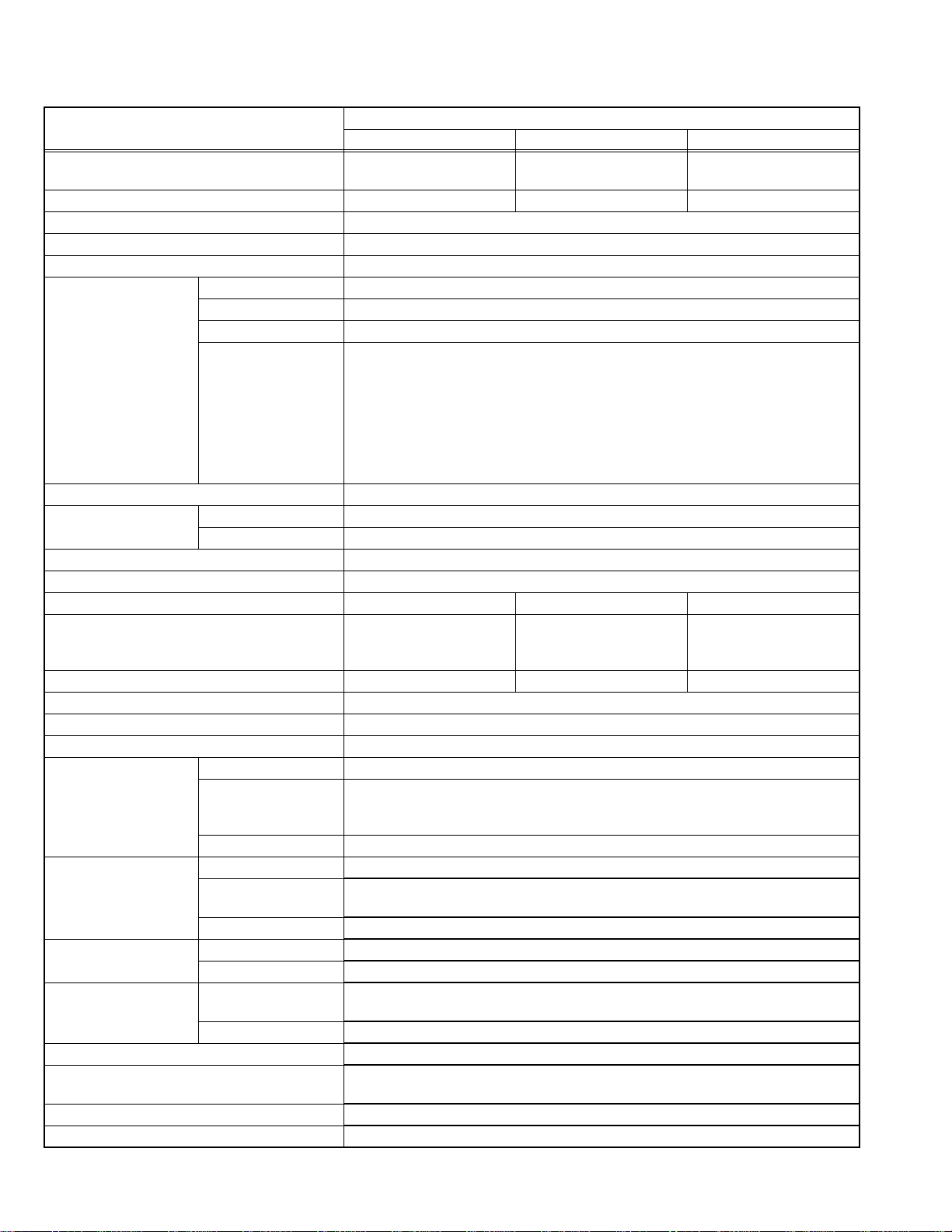
SPECIFICATION
Items
Dimensions (W × H × D)
Mass 43.0kg (94.6Ibs) 64.0kg (140.8Ibs) 85.0kg (187.0Ibs)
TV RF System CCIR(M)
Color System NTSC
Sound System BTSC (Multi Channel Sound)
TV Receiving Channels
and Frequency
TV / CATV Total Channel 180 Channels
Intermediate Frequency Video IF Carrier 45.75 MHz
Color Sub Carrier 3.58 MHz
Power Input AC120V , 60Hz
Power Consumption 140W 160W ←
Picture Tube (Visible size) 68cm (27”)
High Voltage 30.0kV ±1.3kV 31.4kV ±1.3kV ←
Speaker 6.5cm × 13cm (2-1/2" × 5"), Oval type × 2
Audio Power Output 10W + 10W
Antenna Terminal (VHF / UHF) F-type connector, 75 Ω unbalanced
Input1 (Rear) Video 1V(p-p), negative sync, 75 Ω, RCA pin jack × 1
Input2 (Rear) Video 1V(p-p), negative sync, 75 Ω, RCA pin jack × 1
Component Video Y : 1V(p-p), negative sync, 75 Ω, RCA pin jack × 1
Input3 (Front) Video 1V(p-p), negative sync, 75 Ω, RCA pin jack × 1
Input4 (Rear) Component Video Y : 1V(p-p), negative sync, 75 Ω, RCA pin jack × 1
Subwoofer Output (Audio) More than 0 to 1000mV (rms)(+2.2dBs), low impedance, RCA pin jack × 1
Audio Output (Fix) 500mV(rms)(-4dBs), low Impedance, (400kHz when modulated 100%),
AV COMPULINK lll 3.5mm mini jack × 1
Remote Control Unit RM-C1251G (AA/R6/UM-3 battery × 2)
Design & specifications are subject to change without notice.
VHF LOW 02ch~06ch : 54MHz~88MHz
VHF HIGH 07ch~13ch : 174MHz~216MHz
UHF 14ch~69ch : 470MHz~806MHz
CATV 54MHz~804MHz
Sound IF Carrier 41.25 MHz (4.5MHz)
S-video Mini DIN 4-pin × 1
Audio 500mV(rms)(-4dBs), high impedance, RCA pin jack × 2
Audio 500mV(rms)(-4dBs), high impedance, RCA pin jack × 2
Audio 500mV(rms)(-4dBs), high impedance, RCA pin jack × 2
Audio 500mV(rms)(-4dBs), high impedance, RCA pin jack × 2
AV-27FA54 AV-32FA54 AV-36FA54
82.9 cm × 59.3 cm × 51.9cm
(32-3/4" × 23-3/8" × 20-1/2")
Low Band : 02~06, A-8 by 02~06&01
High Band : 07~13 by 07~13
Mid Band : A~I by 14~22
Super Band : J~W by 23~36
Hyper Band : W+1~W+28 by 37~64
Ultra Band : W+29~W+84 by 65~125
Sub Mid Band : A8, A4~A1 by 01, 96~99
Measured diagonally
(H : 54.4cm × W : 41.8cm)
Y : 1V(p-p), negative sync, 75 Ω
C : 0.286V(p-p)(burst signal), 75 Ω
Pb/Pr : 0.7V(p-p), 75 Ω, RCA pin jack × 2
Pb/Pr : 0.7V(p-p), 75 Ω, RCA pin jack × 2
RCA pin jack × 2
93.9 cm × 68.5 cm × 57.0cm
(H : 65.6cm × W : 49.6cm)
Contents
(37" × 27" × 22-1/2")
80cm (32”)
Measured diagonally
102.3 cm × 75.6 cm × 61.3cm
(40-3/8" × 29-7/8" × 24-1/4")
90cm (36”)
Measured diagonally
(H : 74.0cm × W : 55.9cm)
1-2 (No.52115)
Page 3
SECTION 1
PRECAUTION
1.1 SAFETY PRECAUTIONS
(1) The design of this product contains special hardware, many
circuits and components specially for safety purposes. For
continued protection, no changes should be made to the original
design unless authorized in writing by the manufacturer.
Replacement parts must be identical to those used in the original
circuits. Service should be performed by qualified personnel only.
(2) Alterations of the design or cir cuitry of the pr oducts shou ld n ot be
made. Any design alterations or additions will void the
manufacturer's warranty and will further relieve the manufacturer
of responsibility for personal injury or property damage resulting
therefrom.
(3) Many electrical and me chanical parts in the products have special
safety-related characteristics. These characteristics are often not
evident from visual inspection nor can the protection afforded by them
necessarily be obtained by using replacement components rated for
higher voltage, wattage, etc. Replacement parts w hich have these
special safety characteristics are identified in the parts list of Service
manual. Electrical components having such features are
identified by shading on the schematics and by ( ) on the
parts list in Service manual. The use of a substitute replacement
which does not have the same safety characteristics as the
recommended replacement part shown in the part s list of Service
manual may cause shock, fire, or other hazards.
(4) Use isolation transformer when hot chassis.
The chassis and any sub-chassis contained in some products are
connected to one side of the AC power line. An isolation
transformer of adequate capacity should be inserted between the
product and the AC power supply point while performing any
service on some products when the HOT chassis is exposed.
(5) Don't short between the LIVE side ground and ISOLATED (NEU-
TRAL) side ground or EARTH side ground when repairing.
Some model's power circuit is partly different in the GND. The difference of the GND is shown by the L IVE : ( ) side GND, the ISOLATED (NEUTRAL) : ( ) side GND and EARTH : ( ) side GND.
Don't short between the LIVE side GND and ISOLATED (NEUTRAL)
side GND or EARTH side GND and never measu re the LIVE side
GND and ISOLATED (NEUTRAL) side GND or EARTH side GND at
the same time with a measuring apparatus (oscilloscope etc.). If
above note will not be kept, a fuse or any parts will be broken.
(6) If any repair has been made to the chassis, it is recommended that
the B1 setting should be checked or adjusted (See B1 POWER
SUPPLY check).
(7) The high voltage applied to the picture tube must conform with that
specified in Service manual. Excessive high voltage can cause an
increase in X-Ray emission, arcing and possible component
damage, therefore operation under excessive high voltage
conditions should be kept to a minimum, or should be prevented.
If severe arcing occurs, remove the AC power immediately and
determine the cause by visual inspection (incorrect installation,
cracked or melted high voltage harness, poor soldering, etc.). To
maintain the proper minimum level of soft X-Ray emission,
components in the high voltage circuitry including the picture tube
must be the exact replacements or alternatives approved by the
manufacturer of the complete product.
(8) Do not check high voltage by drawing an arc. Use a high voltage
meter or a high voltage probe with a VTVM. Discharge the picture
tube before attempting meter connection, by connecting a clip lead
to the ground frame and connecting the other end of the lead
through a 10kΩ 2W resistor to the anode button.
(9) When service is required, observe the original lea d dress. Extra
precaution should be given to assure correct lead dress in the high
voltage circuit area. Where a short circuit has occurred, those
components that indicate evidence of overheating should be
replaced. Always use the manufacturer's replacement
components.
(10) Isolation Check (Safety fo r Electrical Shock Hazard)
After re-assembling the product, always perform an isolation
check on the exposed metal parts of the cabinet (antenna
terminals, video/audio input and output terminals, Control knobs,
metal cabinet, screw heads, earphone jack, control shafts, etc.) to
be sure the product is safe to operate without danger of electrical
shock.
a) Dielectric Strength Test
The isolation between the AC primary circuit and all metal parts
exposed to the user, particularly any exposed metal part having a
return path to the chassis should withstand a voltage of 1100V AC
(r.m.s.) for a period of one second.
(. . . . Withstand a voltage of 1100V AC (r.m.s.) to an appliance rat-
ed up to 120V, and 3000V AC (r.m.s.) to an appliance rated 200V
or more, for a period of one second.) This method of test requires
a test equipment not generally found in the service trade.
b) Leakage Current Check
Plug the AC line cord directly into the AC outlet (do not use a line
isolation transformer during this check.). Using a "Leakage
Current Tester", measure the leakage current from each exposed
metal part of the cabinet, particularly any exposed metal part
having a return path to the chassis, to a known good earth ground
(water pipe, etc.). Any leakage current must not exceed 0.5mA AC
(r.m.s.).
However, in tropical area, this must not exceed 0.2mA AC (r.m.s.).
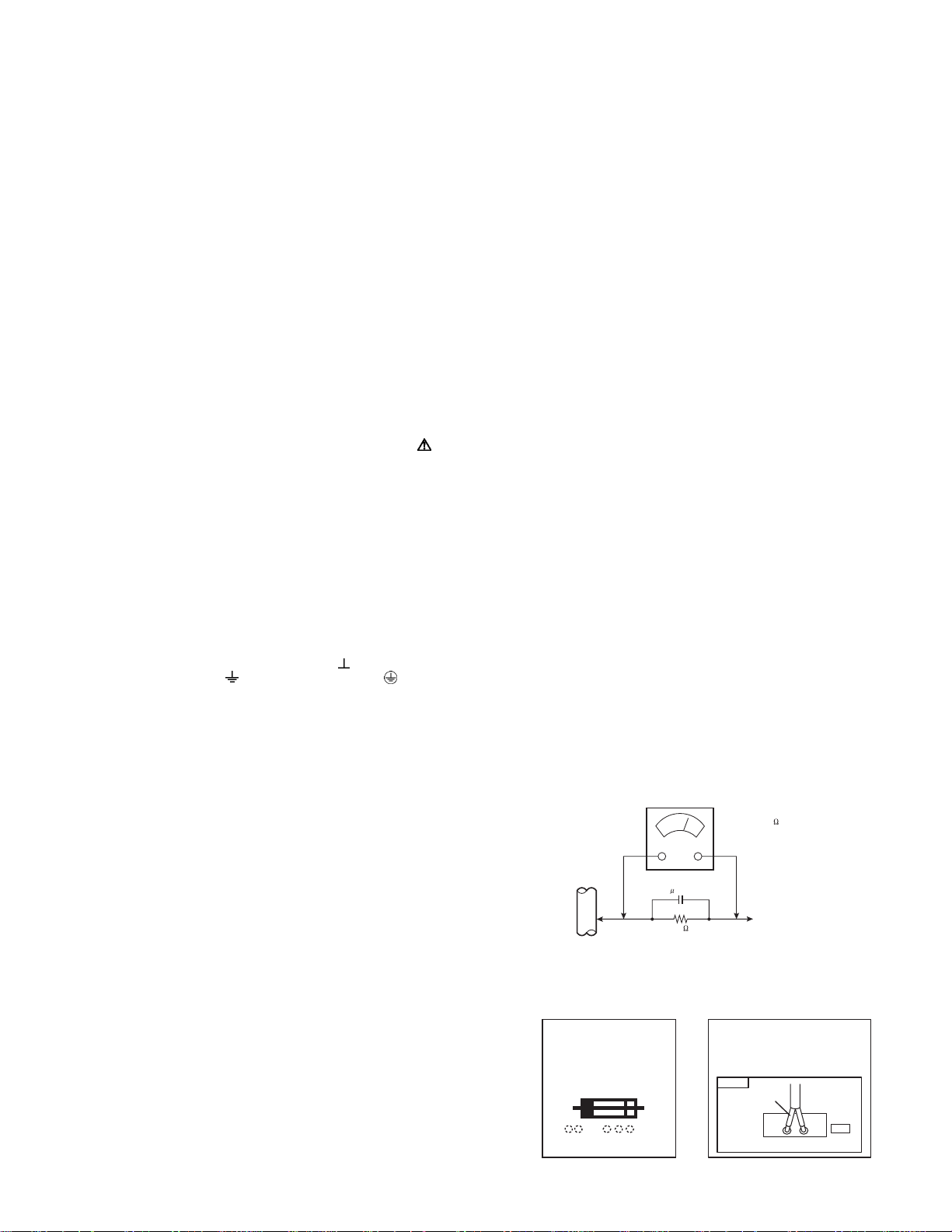
Alternate Check Method
Plug the AC line cord directly into the AC outlet (do not use a
line isolation transformer during this check.). Use an AC
voltmeter having 1000Ω per volt or more sensitivity in the
following manner. Connect a 1500Ω 10W resistor paralleled by
a 0.15µF AC-type capacitor between an exposed metal part and
a known good earth ground (water pipe, etc.). Measure the AC
voltage across the resistor with the AC voltmeter. Move the
resistor connection to each exposed metal part, particularly any
exposed metal part having a return path to the chassis, and
measure the AC voltage across the resistor. Now, reverse the
plug in the AC outlet and repeat each measurement. Any
voltage measured must not exceed 0.75V AC (r.m.s.). This
corresponds to 0.5mA AC (r.m.s.).
However, in tropical area, this must not exceed 0.3V AC
(r.m.s.). This corresponds to 0.2mA AC (r.m.s.).
AC VOLTMETER
(HAVING 1000 /V,
OR MORE SENSITIVITY)
0.15 F AC-TYPE
PLACE THIS PROBE
1500 10W
(11) High voltage hold down circuit check.
GOOD EARTH GROUND
ON EACH EXPOSED
METAL PART
After repair of the high voltage hold down circuit, this circuit shall
be checked to operate correctly.See item "How to check the high
voltage hold down circuit".
This mark shows a fast
operating fuse, the
letters indicated below
show the rating.
A V
POWER CORD
REPLACEMENT WARNING.
Connecting the white line side of power
cord to "WHT" character side.
PWB
White line side
WHT
PW
(No.52115)1-3
Page 4
SECTION 2
SPECIFIC SERVICE INSTRUCTIONS
2.1 FEATURES
• New chassis (GJ2) design enables use of a single board with
simplified circuitry.
• Users can make fun to connect the DVD player with the
component video signal input terminal.
• Provided with miniature tuner (TV/CATV).
• Multifunctional remote control permits picture adjustment.
• Adoption of the CHANNEL GUARD function prevents the
specific channels from being selected, unless the "ID number"
is key in.
2
C bus control utilizes single chip ICs.
•I
• Adoption of the VIDEO STATUS / THEATER PRO. function.
• Adoption of the ON/OFF TIMER and SLEEP TIMER function.
• Built-in V-CHIP system.
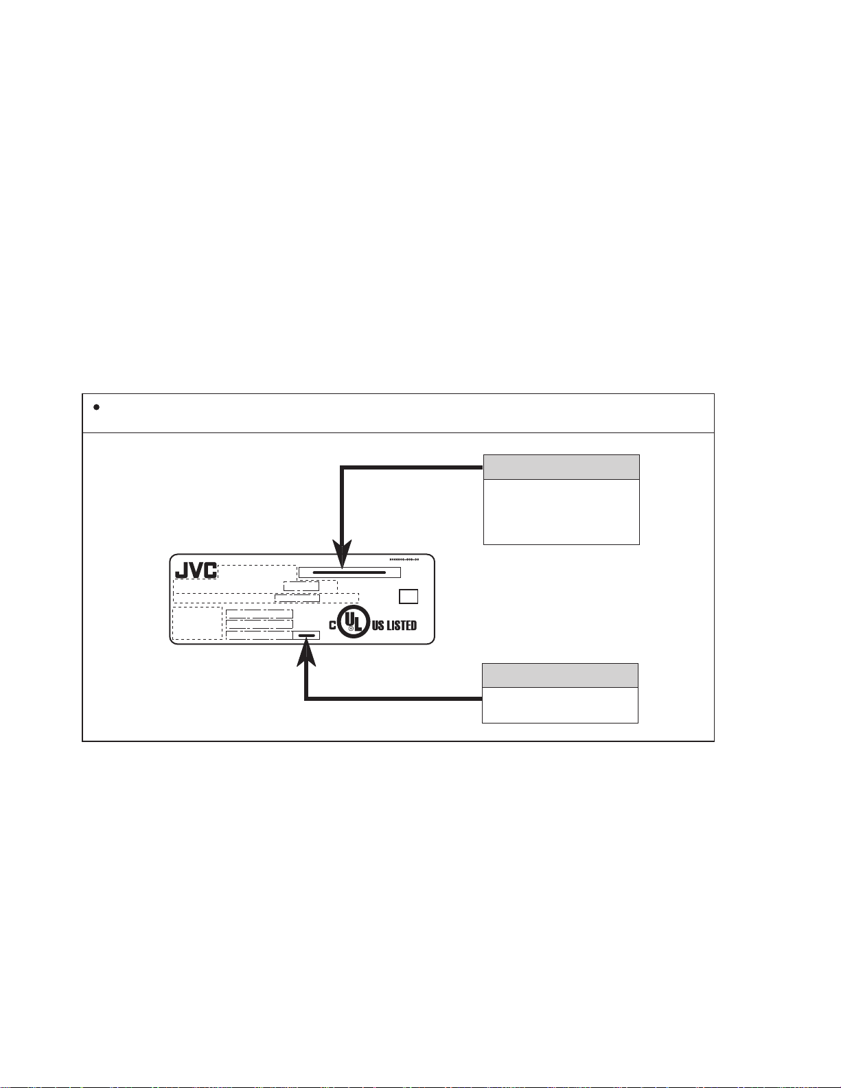
2.2 HOW TO IDENTIFY MODELS
How to recognize from the appearance of the model concerned is written below. Please distinguish from several contents
currently printed on the rating label.
• Closed-caption broadcasts can be viewed.
• Built-in AHS (Advanced Hyper Surround) system.
• S-VIDEO input terminal for taking best advantage of Super
VHS.
• Digital Comb filter Improved picture quality.
• Adoption of the ASPECT MODE (4:3/ 16:9) function.
• By pushing the EZ SURF key, Back Program Information can
be displayed in written from program Information uses a CALL
LETTER (broadcasting station ID), a Network name and a
Program name of XDS data, and collectÅfs tuning of the tuner
for PIP one by one.
• Two programs can be displayed on the screen by the 2 tuners
PIP circuit.
MODEL NAME
AC 120V 60Hz
MODEL NO.
TV SCREEN SIZE : DIAGONAL
CHASSIS NO.
MANUFACTURED
SERIAL NO.
W
INCHES
ME
VIDEO EQUIPMENT
4C43
AV-27FA54
or AV-32FA54
or AV-36FA54
DISTINGUISH NAME
ASA or AZA or AYA
1-4 (No.52115)
Page 5
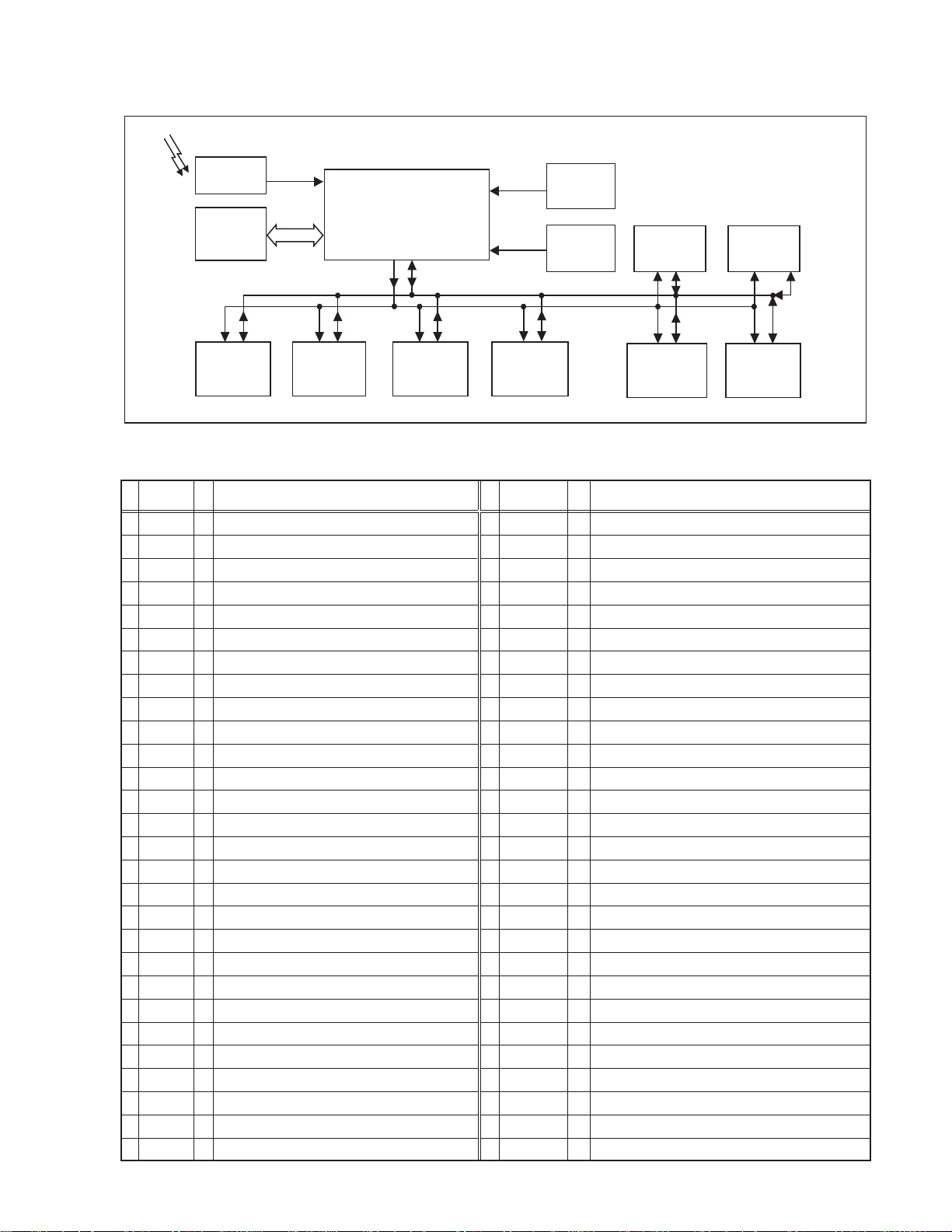
2.3 TECHNINAL INFORMATION
2.3.1 SYSTEM BLOCK DIAGRAM
REMOCON
REMOCON
RECEIVER
IC702
MEMORY
SCL0 SDA0
IC5001
MTS
TONE/VOL
SCL1
SDA1
SCL0 SDA0 SCL0 SDA0
IC5501
LATCH&
AV SW
2.3.2 MAIN MI-COM (CPU) PIN FUNCTION
Pin
Pin name
No.
AFT2
1
AFT1
2
KEY
3
uP DVss
4
Reset
5
Xout
6
Xin
7
TEST
8
uP_DVDD
9
AGC_MUTE
10
UP_VVss
11
TV_HGND
12
FBP_SCP
13
Hout
14
H_Vcc_9V
15
HAFC_1
16
Vsaw
17
Vout
18
EW_out
19
Xray
20
Ys
21
Cb_input
22
Y_input
23
Cr_input
24
DVcc_3.3V
25
V3in/Cin
26
EHT_in
27
28
V2in/Y
I/O
AFT voltage for sub tuner (Tuning frequency control)
I
AFT voltage for main tuner (Tuning frequency control)
I
Key scan for front control [No signal : H]
I
GND
-
CPU reset
I
CPU system clock : 8MHz oscillation
O
CPU system clock : 8MHz oscillation
I
GND
-
5V
-
AGC muting for main tuner (when channel select) [Muting : H]
O
GND
-
GND
-
Flyback pulse (H. pulse)
I
H. drive (oscillation)
O
9V (for H. oscillation start)
-
H. AFC filter
-
V. saw filter
-
V. drive
O
Parabola waveform (for sidepin correection)
O
X-ray detection (for protection) [Detection : H]
I
PIP area pulse [sub picture on:H]
I
Cb(external) /B-Y(PIP) signal
I
Y signal (external /PIP)
I
Cr(external) /R-Y(PIP) signal
I
3.3V
-
Chroma signal (for YC separation output)
I
Not used
I
Y signal (for YC separation output)
I
Function
IC201
MAIN MI-COM /
VIDEO PROCESS /
DEF. PROCESS
SCL0 SDA0
IC5201
3-LINE YC SEP.
AFT1
AFT2
SCL0 SDA0
TU001
MAIN TUNER
Pin
Pin name
No.
YCD_GND
29
Vin1
30
ABCL
31
Monitor
32
Black_Det
33
SVM_out
34
APL_Fil
35
APC_Fil
36
3.58MHz
37
YC_Vcc_5V
38
R_out
39
G_out
40
B_out
41
RGB_Vcc_9V
42
IK in
43
TV_DGND
44
uP_MPAGND
45
uP_MPAVDD
46
MAIN_POWER
47
HAZARD
48
SDAO
49
SCLO
50
SDA1
51
AGC ADJUST
52
SCL1
53
LED
54
REMOCON
55
COMPULINK
56
IC101
MAIN IF DET
IC4101
SUB IF DET
TU4001
SUB TUNER
SCL0 SDA0
SCL0 SDA0
IC502
D-A CONVERTER
I/O
GND
-
Not used
I
Current for automatic beam (brightness)/contrast limit
I
Clamp pulse (for Component / PIP switch)
O
Black level detection filter
-
Y signal for scan velocity modulation
O
Average picture level filter
-
Automatc phase control filter
-
Color sub carrier (3.58MHz) for 3-line digital comb filter [IC5201]
O
5V (for video process circuit)
-
R signal
O
G signal
O
B signal
O
9V (for RGB process circuit)
-
Not used
I
GND
-
GND
-
5V
-
Power on/off switching control [Powen on : L]
O
B1 over cuurent / V. amplitude detection (for protect) [Defective : H]
I
Data for Inter IC control bus (for various devices)
I/O
Clock for Inter IC control bus (for various devices)
O
Data for Inter IC control bus (for main memory)
I/O
AGC adjustment (for tuner) <S45 in Service menu>
O
Clock for Inter IC control bus (for main memory)
O
POWER / ON TIMER LED lndication [lighting : L]
O
Remote control sensor input [No input : H]
I
AV COMPULINK lll control [No input : H]
I
IC4301
PIP CONTROL
SCL0 SDA0
SCL0 SDA0
IC5701
EXPANSION
I/O
Function
(No.52115)1-5
Page 6
2.4 MAIN DIFFERENCE LIST Item
CRT (Picture Tube) Size 27V (Diagonally)
CRT Surface Treatment Crear + Coating Tint Tint
Electric Gun Non-DAF DAF DAF
High Voltage 30kV±1.3kV 31.4kV±1.3kV 31.4kV±1.3kV
Dimensions (W × H × D) "82.9cm × 59.3cm × 51.9cm
(32-3/4" × 23-3/8" × 20-1/2")
Mass 43.0 kg (94.6 Ibs) 64.0 kg (140.8 Ibs) 85.0 kg (187.0 Ibs)
MAIN PWB ASSY SGJ-1513A-M2 SGJ-1514A-M2 SGJ-1511A-M2 SGJ-1515A-M2 SGJ-1512A-M2
PIP PWB ASSY SGJ-4001A-M2 ←←← ←
DAF PWB ASSY --- --- SGJ-2503A-M2 SGJ-2502A-M2 SGJ-2501A-M2
CRT SOCKET PWB ASSY SGJ-3502A-M2 SGJ-3506A-M2 SGJ-3504A-M2 SGJ-3503A-M2 SGJ-3501A-M2
FRONT CONTROL
PWB ASSY
PICTURE TUBE (ITC) A68QCP893X003
DEG COIL QQW0090-001 ← QQW0107-001 QQW0176-001 QQW0122-001
FRONT CABINET ASSY LC11556-001C-A ← LC11531-001B-A ← LC11557-001B-A
REAR COVER LC11555-001C-A ← LC11533-001C-A ← LC11559-001C-A
SGJ-6501A-M2 ← SGJ-6502A-M2 ← SGJ-6503A-M2
AV-27FA54 AV-32FA54 AV-36FA54
ASA AZA AYA AZA AYA
(H:55.4cm × W:41.8cm)
A68QCU754X62N
32V (Diagonally)
(H:65.6cm × W:49.6cm)
"93.9cm × 68.5cm × 57.0cm
(37" × 27" × 22-1/2")
A80AJZ90X03 A80ERF042X17 A90AJZ90X02
36V (Diagonally)
(H:74.0cm × W:55.9cm)
"102.3cm × 75.6cm × 61.3cm
×
(40-3/8"
29-7/8" × 24-1/4")
1-6 (No.52115)
Page 7
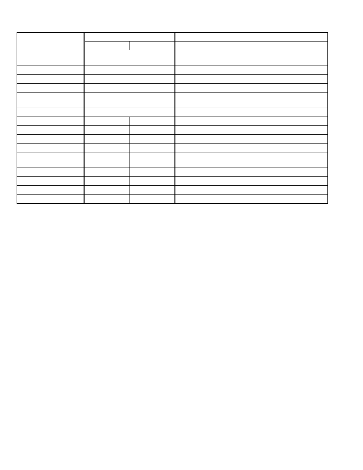
2.5 FUNCTIONS FRONT PANEL CONTROL
VIDEO L / MONO - AUDIO - R
1
a
INPUT-3 TERMINAL
1
VIDEO
2
AUDIO L/MONO
3
AUDIO R
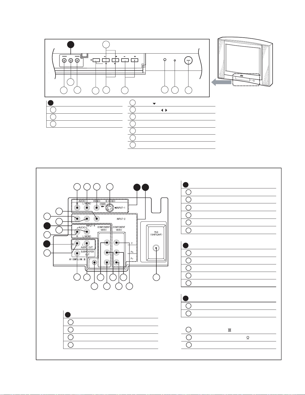
REAR TERMINAL
5
7
6
C
11
12
a
INPUT- 3
2
3
MENU
4
432 1
6
5
OPERATE
VOLUMECHANNEL
7
4
MENU( ) button
5
OPERATE( / ) button (for MENU)
6
CHANNEL(-/+) buttons
7
VOLUME(-/+) buttons
8
REMOTE CONTROL SENSOR
9
POWER ON/ ON TIMER INDICATOR
10
POWER SW button
ON TIMER
8
9
A B
POWER
10
B
INPUT-2 TERMINAL
5
VIDEO
6
AUDIO L/MONO
7
AUDIO R
8
COMPONENT-Y
9
COMPONENT-P
10
COMPONENT-P
b
r
D
17
20
16
13 14 19
A
INPUT-1 TERMINAL
1
S-VIDEO
2
VIDEO
3
AUDIO L/MONO
4
AUDIO R
C
INPUT-4 TERMINAL
11
AUDIO L/MONO
12
AUDIO R
13
COMPONENT-Y
14
9
1518
810
COMPONENT-P
15
COMPONENT-Pr
D
AUDIO OUTPUT TERMINAL (Fixed)
16
AUDIO L
17
AUDIO R
18
AV COMPULINK TERMINAL
19
ANTENNA TERMINAL 75 (VHF/UHF)
20
SUBWOOFER OUT
b
(No.52115)1-7
Page 8
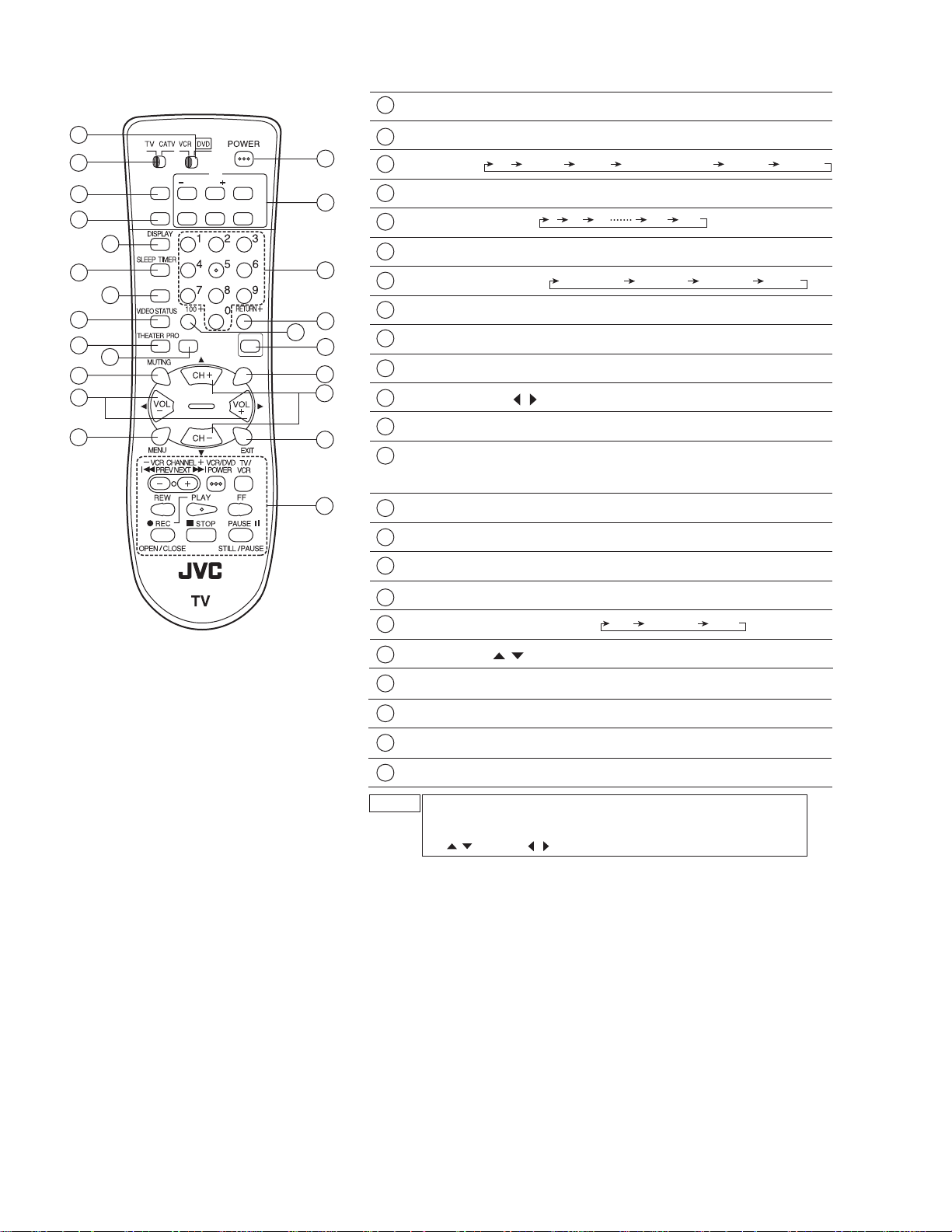
REMOTE CONTROL UNIT
1
POWER key
22
23
10
11
12
2
EZ SURF key:
16
1
13
14
15
17
18
19
20
21
2
3
5
7
8
EZ SURF CHANNEL ON/MOVE
4
SOUND
6
9
PIP
SOURCEINPUT FREEZE SWAP
ASPECT
RM-C1250G
LIGHT
C.C.
3
INPUT key:
4
DISPLAY key
5
SLEEP TIMER key:
6
SOUND key:
7
VIDEO STATUS key:
8
THEATER PRO key
9
ASPECT key:
10
MUTING key
11
VOL+/- & VOL /
12
MENU key
13
PIP CONTROL key:
14
CHANNEL NUMBER keys
15
RETURN+ key
16
100+ key
LIGHT key
17
18
C.C.
(CLOSED CAPTION)
Back program can be displayed
TV VIDEO1 VIDO2 V2-COMPONENT VIDEO3 VIDEO4
0 15 30 165 180
AHS and BBE ON/OFF can be displayed
STANDARD DYNAMIC THEATER GAME
Can be changed to 4:3 and 16:9 screen
(for SERVICE MENU)
(ON/MOVE, CHANNEL, SWAP, FREEZE and SOURCE keys)
Press the ON/MOVE key; PIP screen can be dispalyed
OFF CAPTION TEXT
key:
keys
19
CH+/- & CH /
EXIT key
20
VCR CONTROL key
21
22
VCR / DVD switch
23
TV / CATV switch
NOTE
The CH+/- keys and VOL+/- keys operate CHANNEL and
VOLUME normally.
These keys are also used to navigate SERVICE MENU as the
CH / and VOL / keys.
(for SERVICE MENU)
keys
1-8 (No.52115)
Page 9

SECTION 3
DISASSEMBLY
3.1 DISASSEMBLY PROCEDURE
3.1.1 REMOVING THE REAR COVER
(1) Disconnect the power plug from wall outlet.
(2) As shown in the Fig.1, remove the 11 screws [A].
(3) Withdraw the REAR COVER backward.
3.1.2 REMOVING THE AV TERMINAL BOARD
• Remove the REAR COVER.
(1) As shown in Fig.1, remove the 6 screws [B].
(2) Withdraw the AV TERMINAL BOARD toward you.
3.1.3 REMOVING THE CHASSIS
• Remove the REAR COVER.
• Remove the AV TERMINAL BOARD.
(1) Slightly raise the both sides of CHASSIS by hand.
(2) Remove the 2 claws under the both side of the CHASSIS
from the front cabinet.
(3) Withdraw the CHASSIS backward.
(If necessary, remove the wire clamp, connectors etc.)
3.1.7 CHECKING THE CHASSIS
To check the PW Board from back side.
(1) Pull out the CHASSIS (refer to REMOVING THE CHASSIS).
(2) Erect the CHASSIS vertically so that you can easily check
the back side of the PW Board.
CAUTION :
• When erecting the CHASSIS, be careful so that there will be
no contacting with other PW Board.
• Before turning on power, make sure that the wire connector
is properly connected.
• Wh en co nduc tin g a che ck with pow er su ppli ed, be sure
to confirm that the CRT EARTH WIRE (BRAIDED ASS'Y)
is connected to the CRT SOCKET PWB.
3.1.8 WIRE CLAMPING AND CABLE TYING
(1) Be sure to clamp the wire.
(2) Never remove the cable tie used for tying the wires together.
Should it be inadvertently removed, be sure to tie the wires
with a new cable tie.
3.1.4 REMOVING THE SPEAKER
• Remove the REAR COVER.
(1) As shown in Fig.1, remove the 2 screws [C].
(2) Remove the 4 screws [D] and taking out the SPEAKER.
(3) Follow the same steps when removing the other hand
SPEAKER.
NOTE :
When remove the 2 screws [C] of the SPEAKER, taking out
the lower side screw first, and then takeing out the upper one.
3.1.5 REMOVING THE LED & POWER SW PWB
• Remove the REAR COVER.
(1) Remove the 2 screws [E] as shown in Fig.1.
(2) Withdraw the LED & POWER SW PWB toward you.
*If necessary, remove the wire clamp, connector etc.
3.1.6 REMOVING THE FRONT CONTROL PWB
• Remove the REAR COVER.
(1) Remove the 2 screws [F] as shown in Fig.1.
(2) Withdraw the FRONT CONTROL PWB toward you.
*If necessary, remove the wire clamp, connector etc.
(No.52115)1-9
Page 10
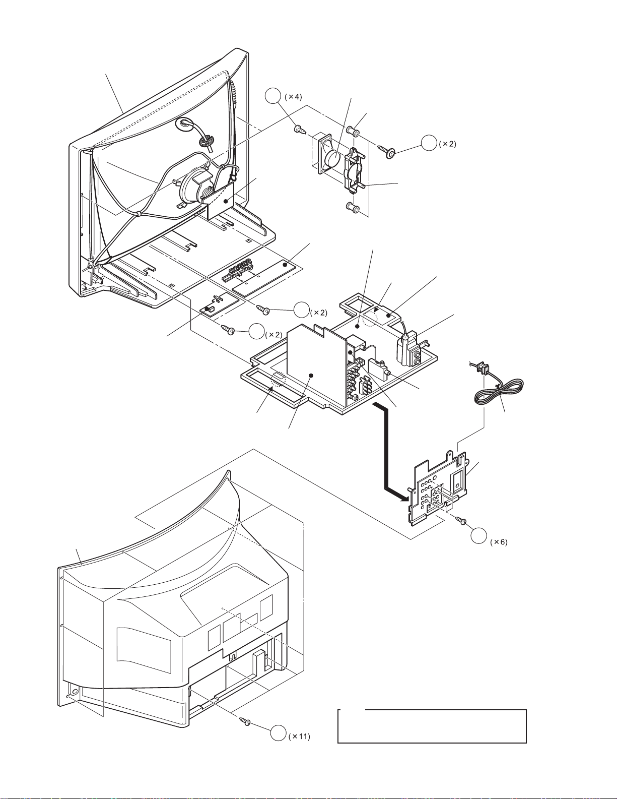
FRONT CABINET
LED&POWER
SW PWB
D
CRT
SOCKET
PWB
E
FRONT
CONTROL
PWB
F
SPEAKER
SPACER
MAIN PWB
CLAW
C
SPEAKER
HOLDER
DAF PWB
HVT
REAR COVER
CLAW
AV SELECTOR
PWB
TUNER
PIP PWB
POWER CORD
AV TERMINAL
BOARD
B
1-10 (No.52115)
A
NOTE
This exploded view describes about the AV-36FA54.
You can use the exploded view for disassembling the
AV-27FA54 / AV-32FA54 in the same step as for this one.
Fig.1
Page 11
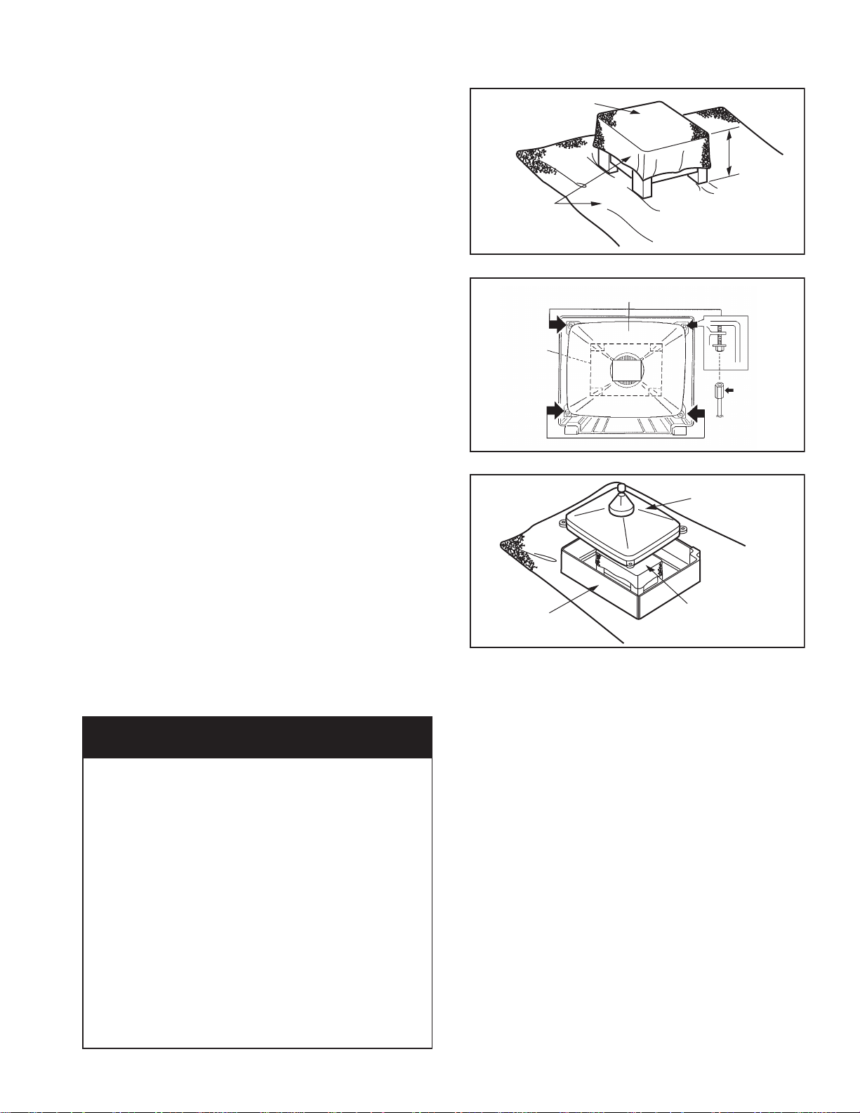
3.2 REMOVING THE CRT
NOTE:
• Replacement of the CRT should be performed by 2 or more
persons.
• After removing the REAR COVER, CHASSIS etc.,
(1) Putting the CRT change table on soft cloth, the CRT
change table should also be covered with such soft cloth
(shown in Fig. 3).
(2) While keeping the surface of CRT down, mount the TV set
on the CRT change table balanced will as shown in Fig. 3.
(3) Remove 4 screws marked by arrows with a box type
screwdriver as shown in Fig. 4.
NOTE:
Since the cabinet will drop when screws have been
removed, be sure to support the cabinet with hands.
(4) After 4 screws have been removed, put the ca binet sl owly
on cloth (At this time, be carefully so as not to damage the
front
surface of the cabinet) shown in Fig. 5.
NOTE:
• The CRT should be assembled according to the
opposite sequence of its dismounting steps.
• The CRT change table should preferably be smaller
that the CRT surface, and its height be about 35cm.
CRT CHANGE TABLE
CLOTH
CRT
CHANGE
TABLE
Fig.3
CRT
Fig.4
APPROX.
35cm
BOX
TYPE
SCREW
DRIVER
FOR AV-32FA54/AZA model only
CAUTION FOR DEGAUSSING WORKS
Whenever degaussing works are required due to
distorted images and colors caused by the
replacement of the CRT or other external magnetic
forces, self-degaussing (internal degaussing) should
be carried out without fail instead of degaussing the
monitor from the outside.
Because of the characteristics of the CRT used in this
monitor , the distorted images and colors may worsen
if degaussing the monitor from the outside has been
performed.
Even if external degaussing works have been carried
out, self-degaussing should be performed by turning
the power on the monitor.
When you want to perform self-degaussing of the
monitor whose power is already turned on, turn of f the
power and wait for about 10 minutes before turning the
power on the monitor again for self-degaussing.
CABINET
CRT
CRT
CHANGE T ABLE
Fig.5
(No.52115)1-11
Page 12
3.3 MEMORY IC REPLACEMENT
3.3.1 MEMORY IC
This TV uses memory IC.
This memory IC stores data for proper operation of the video and deflection circuits.
When replacing the memory IC, be sure to use an IC containing this (initial value) data.
3.3.2 MEMORY IC REPLACEMENT PROCEDURE
1. Power off
Switch off the power and disconnect the power cord from the
wall outlet.
2. Replace the memory IC
Be sure to use a memory IC written with the initial setting data.
3. Power on
Connect the power cord to the wall outlet and switch on the
power.
4. Confirm the system constant value
• 12.SYSTEM (SYS) do not adjust normally.
• The adjustment should not be done without signal.
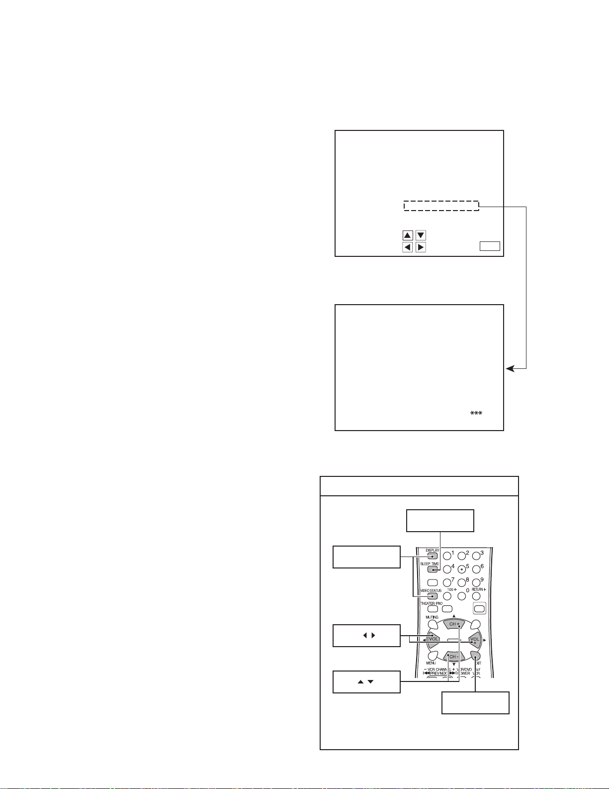
How to enter the SERVICE MENU.
• Before entering the SERVICE MENU, confirm that the
setting of TV/CATV SW of the REMOTE CONTROL UNIT
is at the "TV" side and the setting of VCR/DVD SW of the
REMOTE CONTROL UNIT is at the "VCR" side. If the
switches have not been properly set, you cannot enter the
SERVICE MENU.
(1) Press the [SLEEP TIMER] key and set SLEEP TIMER
for "0 min".
(2) Before disappear the display of SLEEP TIMER set-
tings, simultaneously press the [DISPLAY] key and
[VIDEO STATUS] key of the remote control unit.
(3) The SERVICE MENU screen will be displayed as
shown Fig.1.
How to enter the 12. SYSTEM(SYS).
(1) While the SERVICE MENU is displayed, select the
12.SYSTEM(SYS) item with [CH/] keys, and the
[VOL/] keys is pressed, the screen will be
displayed as shown in Fig.2.
(2) Refer to the "12.SYSTEM(SYS)" table and check the
setting items. If the value is different, select the setting
item with the [CH/] keys and adjust the setting
with the [VOL/] keys. (The letters of the selected
item are displayed in yellow.)
(3) When adjustment has completed, the values store into
memory IC automatically.
(4) Press the [EXIT] key to return the SERVICE MENU
screen.
(5) Then press the [EXIT] key again to return the no rmal
screen.
5. Receiving channel setting
Refer to the OPERATING INSTRUCTIONS (USER'S GUIDE)
and set the receive channels (Channels Preset) as described.
6. User settings
Check the user setting items according to the "FACTRY
SETTING VALUE" table.
Where these do not agree, refer to the OPERATING
INSTRUCTIONS (USER'S GUIDE) and set the items as
described.
7. SERVICE MENU setting
Verify what to set in the SERVICE MENU, and set whatever is
necessary(Fig.1) .
Refer to the SERVICE ADJUSTMENT for setting.
SERVICE MENU
SERV ICE MENU
1.
V/C(S)
3.
SOUND(A)
5.
PIP(PIP)
7.
LOW LIGHT
9.
RF AFC
11.
I2C BUS
SELECT BY
OPERATE BY
SYSTEM (SYS) MODE
SYS01 VIDEO IN
KEY ASSIGNMENT OF REMOTE CONTROL UNIT
DISPLAY &
VIDEO STATUS key
VOL / key
CH / key
2.
DEF(D)
4.
OTHERS(F)
6.
3L Y/C(LYC)
8.
HIGH LIGHT
10.
VOC
12.
SYSTEM(SYS)
EXIT BY
Fig.1
Fig.2
SLEEP TIMER key
SOUND
ASPECT
EXIT
LIGHT
C.C.
EXIT key
[RM-C1250G]
1-12 (No.52115)
Page 13

3.3.3 FACTRY SETTING VALUE
Setting item Setting value Setting item Setting value
REMOTE CONTROLLER KEYS
POWER OFF VIDEO STATUS DYNAMIC
CHANNEL Cable-02 SOUND AHS : OFF
BBE : ON
VOLUME 10 C.C. (Closed Caption) OFF
INPUT TV PIP SOURCE Cable-04
DISPLAY OFF PIP POSITION Left lower side
SETTING OF MENU
PICTURE CLOCK / TIMERS
STANDARD
TINT 0 ←← D.S.T. : OFF
COLOR 0 ← +7 ON / OFF TIMER OFF
PICTURE 0
BRIGHT 0 ←← LANGUAGE ENG
DETAIL 0 +10 +7 FRONT PANEL LOCK OFF
COLOR TEMPERATURE LOW HIGH LOW AUTO SHUT OFF OFF
NOISE MUTING ON CLOSED CAPTION CC1 / T1
SOUND AUTO TUNER SETUP Unnecessary to set
BASS Center CHANNEL SUMMARY Setting Channel
TREBLE Center V-CHIP OFF
BALANCE Center SET LOCK CODE (0000)
MTS STEREO XDS ID ON
DYNAMIC
+14(27")
+17(32", 36")
GAME SET CLOCK MANUAL
TIME ZONE : PACIFIC
-10
PULITY [AV-36FA54 only] Center
INITIAL SETUP
Guard channel : All OFF
3.3.4 SERVICE MENU SETTING ITEMS
Service menu Setting item Remarks
1.V/C(S) S01~S48 VIDEO / CHROMA related circuit adjustment mode
2.DEF(D) D01~D33 DEFLECTION related circuit adjustment mode
3.SOUND(A) A01~A08 SOUND related circuit adjustment mode
4.OTHERS(F) F01~F28 Whole system related items adjustment mode
[Fixed value. Do not adjust]
5.PIP(PIP) PIP01~PIP52 PIP related circuit adjustment mode
6.3LY/C(LYC) LYC01~LYC12 3 line YC separation related circuit adjustment mode
[Fixed value. Do not adjust]
12.SYSTEM(SYS) SYS01~SYS27 This mode is used when setting up the whole system
[Fixed value. Do not adjust]
(No.52115)1-13
Page 14
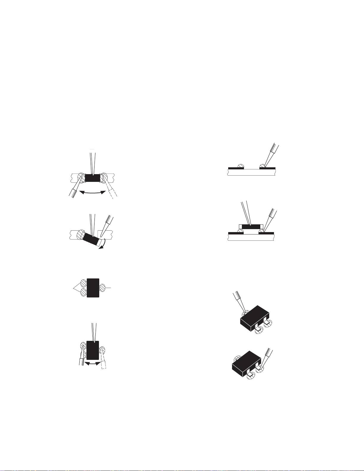
3.4 REPLACEMENT OF CHIP COMPONENT
3.4.1 CAUTIONS
(1) Avoid heating for more than 3 seconds.
(2) Do not rub the electrodes and the resist parts of the pattern.
(3) When removing a chip part, melt the solder adequately.
(4) Do not reuse a chip part after removing it.
3.4.2 SOLDERING IRON
(1) Use a high insulation soldering iron with a thin pointed end of it.
(2) A 30w soldering iron is recommended for ea sily removing parts.
3.4.3 REPLACEMENT STEPS
1. How to remove Chip parts
2. How to install Chip parts
[Resistors, capacitors, etc.]
(1) As shown in the figure, push the part with tweezers and
alternately melt the solder at each end.
(2) Shift with the tweezers and remove the chip part.
[Transistors, diodes, variable resistors, etc.]
(1) Apply extra solder to each lead.
SOLDER
SOLDER
[Resistors, capacitors, etc.]
(1) Apply solder to the pattern as indicated in the figure.
(2) Grasp the chip part with tweezers and place it on the
solder. Then heat and melt the solder at both ends of the
chip part.
[Transistors, diodes, variable resistors, etc.]
(1) Apply solder to the pattern as indicated in the figure.
(2) Grasp the chip part with tweezers and place it on the
solder.
(3) First solder lead A as indicated in the figure.
(2) As shown in the figure, push the part with tweezers and
alternately melt the solder at each lead. Shift and remove
the chip part.
NOTE :
After removing the part, remove remaining solder from the
pattern.
1-14 (No.52115)
A
B
C
(4) Then solder leads B and C.
A
B
C
Page 15

SECTION 4
ADJUSTMENT
4.1 ADJUSTMENT PREPARATION
(1) There are 2 ways of adjusting this TV : One is with the REMOTE CONTROL UNIT and the other is the conventional
method using adjustment parts and components.
(2) The adjustment using the REMOTE CONTROL UNIT is made on the basis of the initial setting values. The setting values
which adjust the screen to the optimum condition can be different from the initial setting values.
(3) Make sure that connection is correctly made AC to AC power source.
(4) Turn on the power of the TV and measuring instruments for warning up for at least 30 minutes before starting adjustments.
(5) If the receive or input signal is not specified, use the most appropriate signal for adjustment.
(6) Never touch the parts (such as variable resistors, transformers and condensers) not shown in the adjustment items of this service
adjustment.
(7) Preparation for adjustment. Unless otherwise specified in the adjustment items, preset the following functions with the REMOTE
CONTROL UNIT.
Item Preset value
VIDEO STATUS STANDARD
TINT, COLOR, PICTURE, BRIGHT, DETAIL Center
BASS, TREBLE, BALANCE Center
MTS STEREO
4.2 MEASURING INSTRUMENT AND FIXTURES
(1) DC voltmeter (or digital voltmeter)
(2) Oscilloscope
(3) Frequency counter
(4) Signal generator (Pattern generator) [NTSC]
(5) TV audio multiplex signal generator
(6) Remote control unit
4.3 ADJUSTMENT ITEMS
CHECK ITEM
• B1 POWER SUPPLY check
TUNER / IF CIRCUIT
• IF VCO adjustment
• SUB VCO adjustment
• RF. AGC adjustment
FOCUS
• FOCUS adjustment
DEFLECTION CIRCUIT
• V. SIZE / V. POSITION (4:3) adjustment
• V. SIZE / V. POSITION (16:9) adjustment
• H. POSITION / H. SIZE / SIDE PIN [ (4:3) & (16:9) ] adjustment
• PIP DISPLAY POSITION adjustment
VIDEO CIRCUIT
• WHITE BALANCE(High Light & Low Light) adjustment
• PIP WHITE BALANCE (High Light) adjustment
• SUB BRIGHT adjustment
• SUB CONTRAST adjustment
• SUB COLOR adjustment
• SUB TINT adjustment
MTS CIRCUIT
• MTS INPUT LEVEL adjustment
• MTS SEPARATION adjustment
HIGH VOLTAGE HOLD DOWN CIRCUIT
(No.52115)1-15
Page 16

4.4 ADJUSTMENT LOCATIONS / WIRING
HV T
LED & POWER SW PWB
POWER
SW
S7701
SPEAKER
(R)
IC621
POWER /
ON TIMER
INDICATOR
D7701
SS
SENSOR
IC7701
B
SPEAKER
(L)
AV SEL PWB
PIP PWB
CN5006
T4111
SUB VCO
CN007
IC702
memory IC
MAIN PWB
CN004
CPU
IC201
FRONT CONTROL PWB
CN6007B
WHT
MENUVOL CH
F901
PW
BLK
R
DEG
INPUT 3
L/MONO
FRONT
VIDEO
CN6006
FRONT
IC911
CRT
DY
POWER
PLUG
CN5001
AV TERMINAL
CN4002
(TUNER.2)
PIP TUNER
IC101
T111
MAIN VCO
CRT SOCKET PWB
(SOLDER SIDE)
TP-R
(TUNER.1)
K
IC421
51
S1
C
FOR TEST
B1/ X-RAY PROTECTOR CHECK
TP-B
TP-E1
HV
TOP
Q
CN005
CRT EARTH
(BRAIDED ASS'Y)
CP
E1
AV-27FA54
HVT
DAF
FOCUS
SCREEN
DAF PWB
K
CP
Q
AV-32FA54
AV-36FA54
DAF
FOCUS 2
FOCUS 1
SCREEN
1-16 (No.52115)
CN3004
TP-G
TP-E( )
71
TP-E2
CN30E2
CRT EARTH
(BRAIDED ASS'Y)
1
CN3005
V
6
Page 17

DAF PWB
(Except AV-27FA54)
Q
FRONT
PIP PWB
TOP
Q
K
CP
MAIN PWB
K
CP
DAF
DAF
T2701
PIP TUNER
AV SEL PWB
IC
CN4002
FRONT CONTROL PWB
T4111
SUB VCO
CN6006
INPUT 1
INPUT 2
INPUT 4
AUDIO OUT
SUB WOOFER OUT
TOP
CN5006
CN5001
(No.52115)1-17
Page 18

4.5 BASIC OPERATION OF SERVICE MENU
4.5.1 TOOL OF SERVICE MENU OPERATION
Operate the SERVICE MENU with the REMOTE CONTROL UNIT.
4.5.2 SERVICE MENU ITEMS
1. V/C(S) VIDEO / CHROMA related circuit adjustment mode
2. DEFLECTION(D) DEFLECTION related circuit adjustment mode
3. SOUND(A) SOUND related circuit adjustment mode
4. OTHERS(F) Whole system related items adjustment mode [Fixed value. Do not adjust]
5. PIP(PIP) PIP related circuit adjustment mode
6. 3L Y/C(LYC) 3 line YC separation related circuit adjustment mode [Fixed value. Do not adjust]
7. LOW LIGHT White balance of "LOW LIGHT" adjustment mode
8. HIGH LIGHT White balance of "HIGH LIGHT" adjustment mode
9. RF AFC RF AFC related circuit adjustment mode [Fixed value]
10. VCO VCO related circuit adjustment mode
11. I2C BUS I C bus related circuit adjustment mode [Fixed value]
12. SYSTEM(SYS) This mode is used when setting up the whole system [Fixed value. Do not adjust]
4.5.3 BASIC OPERATION OF SERVICE MENU
1. How to enter the SERVICE MENU
Before entering the SERVICE MENU, confirm that the setting
of TV/CATV SW of the REMOTE CONTROL UNIT is at the
"TV" side and the setting of VCR/DVD SW of the REMOTE
CONTROL UNIT is at the "VCR" side. If the switches have not
been properly set, you cannot enter the SERVICE MENU.
(1) Press the [SLEEP TIMER] key and set the SLEEP
TIMER for "0" MIN
(2) Press the [DISPLAY] key and [VIDEO STATUS] key at
the same time to enter the SERVICE MENU screen.
(Fig.1)
SERVICE MENU
SERV ICE MENU
1.
V/C(S)
3.
SOUND(A)
5.
PIP(PIP)
7.
LOW LIGHT
9.
RF AFC
11.
I2C BUS
SELECT BY
OPERATE BY
2.
DEF(D)
OTHERS(F)
4.
3L Y/C(LYC)
6.
HIGH LIGHT
8.
VOC
10.
SYSTEM(SYS)
12.
Fig.1
EXIT BY
2. SERVICE MENU screen selection
(1) In SERVICE MENU (Fig.1), select any of the SUB MENU
items (1.V/C(S)/ 2.DEF(D)/ 3.SOUND(A)/ 4.OTHERS(F)/
KEY ASSIGNMENT OF REMOTE CONTROL UNIT
5.PIP(PIP)/ 6.3L Y/C(LYC)/ 7.LOW LIGHT/ 8.HIGH LIGHT/
9.RF AFC/ 10.VCO/ 11.I2C BUS/ 12.SYSTEM(SYS)) by
TV/CATV
the [CH/] keys.
The letters of the selected items are displayed in yellow.
(2) With the SUB MENU item selected, press the [VOL/]
keys to display each screen.
Then the settings or verifications can be performed.
SLEEP TIMER key
EZ SURF CHANNEL ON/MOVE
SOURCEINPUT FREEZE SWAP
EXI T
VCR/DVD
POWER
PIP
1-18 (No.52115)
DISPLAY &
VIDEO STATUS key
CH / key
VOL / key
EXIT key
Fig.2
SOUND
ASPECT
LIGHT
C.C.
[RM-C1250G]
Page 19

3. Setting method (Fig.3~ Fig.8)
(1) [CH/] keys
Select the SETTING ITEM
(2) [VOL/] keys
Setting the SETTING VALUE of the SETTING ITEM
When the key is released the SETTING VALUE will be stored (memorized).
(3) [EXIT] key
Return to the previous screen.
RECEIVING MODE
(RF/EXT/COMP)
ASPECT MODE
(4:3 / 16:9)
1.V/C(S), 2.DEF(D)
RF 4 : 3 STD LOW
SETTING ITEM
SETTING NO.
(S:signal / D:DEF)
3.AUDIO(A)
A01 IN LEVEL
Fig.3
SETTING VALUE
WHITE BALANCE
(LOW / HIGH)
VIDEO STATUS
(STD / THEA)
The settings for LOW LIGHT and HIGH LIGHT are described
in the WHITE BALANCE page of ADJUSTMENT PROCEDURE.
7.LOW LIGHT
SETTING VALUESETTING ITEM
BRIGHT
R CUTOFF
G CUTOFF B CUTOFF
SETTING VALUE
Fig.6
8.HIGH LIGHT
SETTING ITEM
SETTING NO.
Fig.4
SETTING VALUE
SETTING VALUE
Fig.7
5.PIP(PIP)
SUB PICTURE
The setting for VCO is described in the IF VCO page of
ADJUSTMENT PROCEDURE.
10.VCO
PIP01 BRIGHT
SETTING ITEM
SETTING NO.
SETTING VALUE
Fig.5
TUNER
HIGH LEVEL
REFERENCE LEVEL
LOW LEVEL
SYNC :YES
Fig.8
4. Releasing the SERVICE MENU
(1) After returning to the SERVICE MENU upon completion of the setting work, press the [EXIT] key again.
B DRIVER DRIVE
MAIN
AFC LEVEL
SYNC INPUT
(No.52115)1-19
Page 20

4.5.4 SERVICE MENU FLOW CHART
SUB MENU SUB MENU
1.V/C(S)
RF 4 : 3 STD LOW
SERVICE MENU
SERVICE MENU
1.V/C(S) 2.DEF(D)
3.SOUND(A) 4.OTHERS(F)
5.PIP(PIP) 6.3L Y/C(LYC)
7.LOW LIGHT 8.HIGH LIGHT
9.RF AFC 10.VCO
11.I2C BUS 12.SYSTEM(SYS)
SELECT BY
OPERATE BY EXIT BY
7.LOW LIGHT
EXIT
S01 BRIGHT
2.DEF(D)
RF 4 : 3 STD LOW
D01 V FREQ
3.SOUND(A)
A01 IN LEVEL
4.OTHERS(F)
[Fixed value. Do not adjust]
BRIGHT
8.HIGH LIGHT
9.RF AFC [Fixed value]
TOO HIGH GOOD TOO LOW
TUNER MAIN
AFC ON
FINE
10.VCO
1-20 (No.52115)
F01
5.PIP(PIP)
PIP01 BRIGHT
6.3L Y/C(LYC)
[Fixed value. Do not adjust]
LYC01
TUNER MAIN
HIGH LEVEL
REFERENCE LEVEL
LOW LEVEL
SYNC : YES
11.I2C BUS [Fixed value]
I2C BUS ON
12.SYSTEM(SYS)
[Fixed value. Do not adjust]
SYS01 VIDEO
Page 21

4.6 INITIAL SETTING VALUE OF SERVICE MENU
(1) Adjustment of the SERVICE MENU is made on the basis of the initial setting values ; however, the new setting values which set
the screen in its optimum condition may differ from the initial setting.
(2) Do not change the initial setting values of the setting items NOT LISTED IN ADJUSTMENT PROCEDURE.
(3) --- : This mark described in each table shows "Cannot adjust it."
1.V/C(S) (1/5)
Initial setting value
AV-27FA54
Setting
No.
S01 BRIGHT 64 --- --- --- --- 64 --- --- --- --S02 PICTURE 60 --- --- --- --- 60 --- --- --- --S03 COLOR 50 --- --- --- 52 50 --- --- --- 52
S04 TINT 68 --- --- --- 70 68 --- --- --- 70
S05 DETAIL 33 --- --- 35 40 37 --- --- 39 44
S06BRIGHT +----0+1 -2 ±0---0+1-2±0
S07 PICT+- --- -8 -10 ±0 -5 --- -8 -10 ±0 -5
S08 COLOR +- --- 0 -3 -1 --- --- 0 -3 -1 --S09 TINT+- --- 0 -3 +2 --- --- 0 -3 +2 --S10 DETAIL+- --- --- 0 --- --- --- --- 0 --- ---
item
STANDARD
(4:3)
RF
STANDARD
(16:9)
ASA AZA
RF
STANDARD
(16:9)
THEATER
THEATER
(4:3)
EXTERNAL
(S, CV)
(4:3)
EXTERNAL
(COMPON ENT)
(4:3)
STANDARD
(4:3)
(4:3)
EXTERNAL
(S, CV)
(4:3)
EXTERNAL
(COMPONENT)
(4:3)
Initial setting value
AV-27FA54
Setting
No.
S11
S12
S13
S14 R DRIVE 64 --- --- --- --- --- --- --- 64 --- --- --- --- --- --- --S15 B DRIVE 64 --- --- --- --- --- --- --- 64 --- --- --- --- --- --- --S16 R CUT+- --- ±0 ±0 ±0 -5 --- --- --- --- ±0 ±0 ±0 -5 --- --- --S17 G CUT+- --- ±0 ±0 ±0 ±0 --- --- --- --- ±0 ±0 ±0 ±0 --- --- --S18 B CUT+- --- ±0 ±0 ±0 -6 --- --- --- --- ±0 ±0 ±0 -6 --- --- --S19 R DRV+- --- +5 +13 +7 ±0 --- --- --- --- +5 +13 +7 ±0 --- --- --S20 B DRV+- --- +6 -25 -9 ±0 --- --- --- --- +6 -25 -9 ±0 --- --- --S21
S22 BLACK ST 2 --- 2 --- --- --- --- --- 2 --- 2 --- --- --- --- --S23 DCREST 1 --- 1 --- --- --- --- --- 1 --- 1 --- --- --- --- --S24 DCRSW 1 --- 1 --- --- --- --- --- 1 --- 1 --- --- --- --- ---
item
R CUT OFF
G CUT OFF
B CUT OFF
NTSC MAT
RF/EXT (S,CV) EXT (COMPONENT) RF/EXT (S,CV) EXT (COMPONENT)
STANDARD THEATER STANDARD THEATER STANDARD THEATER STANDARD THEATER
LOW HIGH LOW HIGH LOW HIGH LOW HIGH LOW HIGH LOW HIGH LOW HIGH LOW HIGH
30 --- --- --- --- --- --- --- 30 --- --- --- --- --- --- --30 --- --- --- --- --- --- --- 30 --- --- --- --- --- --- --30 --- --- --- --- --- --- --- 30 --- --- --- --- --- --- ---
3311221133112211
ASA AZA
(No.52115)1-21
Page 22

1.V/C(S) (2/5)
Initial setting value
AV-32FA54
Setting
No.
S01 BRIGHT 64 --- --- --- --- 64 --- --- --- --S02 PICTURE 60 --- --- --- --- 60 --- --- --- --S03 COLOR 50 --- --- --- 45 50 --- --- --- 41
S04 TINT 68 --- --- --- 68 68 --- --- --- 62
S05 DETAIL 33 --- --- 35 40 33 --- --- 35 40
S06 BRIGHT +- --- 0 +1 -2 ±0 --- 0 +1 -2 ±0
S07 PICT+- --- -8 -10 ±0 -3 --- -8 -10 ±0 -3
S08 COLOR +- --- 0 -3 -2 --- --- 0 -3 -2 --S09 TINT+- --- 0 -3 ±0 --- --- 0 -3 +5 --S10 DETAIL+- --- --- 0 --- --- --- --- 0 --- ---
No.
S11
S12
S13
S14 R DRIVE 64 --- --- --- --- --- --- --- 64 --- --- --- --- --- --- --S15 B DRIVE 64 --- --- --- --- --- --- --- 64 --- --- --- --- --- --- --S16 R CUT+- --- ±0 ±0 ±0 -10 --- --- --- --- ±0 ±0 ±0 ±0 --- --- --S17 G CUT+- --- ±0 ±0 ±0 ±0 --- --- --- --- ±0 ±0 ±0 ±0 --- --- --S18 B CUT+- --- ±0 ±0 ±0 -10 --- --- --- --- ±0 ±0 ±0 ±0 --- --- --S19 R DRV+- --- +5 +13 +7 ±0 --- --- --- --- +5 +13 +7 ±0 --- --- --S20 B DRV+- --- +6 -25 -9 ±0 --- --- --- --- +6 -25 -9 ±0 --- --- --S21
S22 BLACK ST 3 --- 2 --- --- --- --- --- 3 --- 2 --- --- --- --- --S23 DCREST 1 --- 1 --- --- --- --- --- 1 --- 1 --- --- --- --- --S24 DCRSW 0 --- 0 --- --- --- --- --- 0 --- 0 --- --- --- --- ---
item
Setting
item
R CUT OFF
G CUT OFF
B CUT OFF
NTSC MAT
RF
STANDARD
(4:3)
STANDARD THEATER STANDARD THEATER STANDARD THEATER STANDARD THEATER
LOW HIGH LOW HIGH LOW HIGH LOW HIGH LOW HIGH LOW HIGH LOW HIGH LOW HIGH
30 --- --- --- --- --- --- --- 30 --- --- --- --- --- --- --30 --- --- --- --- --- --- --- 30 --- --- --- --- --- --- --30 --- --- --- --- --- --- --- 30 --- --- --- --- --- --- ---
3311221133112211
STANDARD
(16:9)
RF/EXT (S,CV) EXT (COMPONENT) RF/EXT (S,CV) EXT (COMPONENT)
AYA AZA
EXTERNAL
THEATER
(4:3)
AYA AZA
(S, CV)
(4:3)
EXTERNAL
(COMPONENT)
(4:3)
Initial setting value
STANDARD
(4:3)
AV-32FA54
RF
STANDARD
(16:9)
THEATER
(4:3)
EXTERNAL
(S, CV)
(4:3)
EXTERNAL
(COMPONENT)
(4:3)
1-22 (No.52115)
Page 23

1.V/C(S) (3/5)
Initial setting value
AV-36FA54
Setting
No.
S01 BRIGHT 64 --- --- --- --S02 PICTURE 60 --- --- --- --S03 COLOR 50 --- --- --- 44
S04 TINT 68 --- --- --- 69
S05 DETAIL 33 --- --- 35 40
S06 BRIGHT +- --- 0 +1 -2 ±0
S07 PICT+- --- -8 -10 ±0 -3
S08 COLOR +- --- 0 -3 -2 --S09 TINT+- --- 0 -3 ±0 --S10 DETAIL+- --- --- 0 --- ---
No.
S11
S12
S13
S14 R DRIVE 64 --- --- --- --- --- --- --S15 B DRIVE 64 --- --- --- --- --- --- --S16 R CUT+- --- ±0 ±0 ±0 -10 --- --- --S17 G CUT+- --- ±0 ±0 ±0 ±0 --- --- --S18 B CUT+- --- ±0 ±0 ±0 -10 --- --- --S19 R DRV+- --- +5 +13 +7 ±0 --- --- --S20 B DRV+- --- +6 -25 -9 ±0 --- --- --S21
S22 BLACK ST 3 --- 2 --- --- --- --- --S23 DCREST 1 --- 1 --- --- --- --- --S24 DCRSW 0 --- 0 --- --- --- --- ---
item
Setting
item
R CUT OFF
G CUT OFF
B CUT OFF
NTSC MAT
RF
STANDARD
(4:3)
STANDARD THEATER STANDARD THEATER
LOW HIGH LOW HIGH LOW HIGH LOW HIGH
30 --- --- --- --- --- --- --30 --- --- --- --- --- --- --30 --- --- --- --- --- --- ---
33112211
STANDARD
(16:9)
Initial setting value
RF/EXT (S,CV) EXT (COMPONENT)
AYA
THEATER
(4:3)
AV-36FA54
AYA
EXTERNAL
(S, CV)
(4:3)
EXTERNAL
(COMPON ENT)
(4:3)
(No.52115)1-23
Page 24

1.V/C(S) (4/5)
Setting
No.
S25
S26 BPF F0 0 0 --S27 KILR OF F 0 0 --S28 KILR SEN 1 1 ---
1.V/C(S) (5/5)
No.
S29
S30 BLUE B 0 ← 000
S31
S32
S33 OSD ABL 0 ← 000
S34
S35
S36 ABL GAIN 0 ← 000
S37 ABL PNT 3 ← 333
S38 Y GAMMA 1 ← 111
S39 Y MUTE 0 ← 000
S40 SVM GAIN 3 ← 333
S41 SVM PH 1 ← 111
S42 WPL 0 ← 000
S43 COL GMM 0 ← 000
S44 V1 GAIN 4 ← 444
S45 AGC ADJ 63 ← 63 63 63
S46
S47 APC CLK 1 ← 111
S48 PIP ADJ 4 ← 8810
item
ASY SHRP
Setting
item
RGB MUTE
VIDEO SW
CMP ABCL
OSD CONT
SUB CONT
VMOFF DE
RF EXTERNAL COMPONENT
444
ASA AZA AYA AZA AYA
0 ← 000
3 ← 333
0 ← 000
7 ← 888
5 ← 555
+3 ← +3 +3 +3
Initial setting value
Initial setting value
AV-27FA54 AV-32FA54 AV-36FA54
1-24 (No.52115)
Page 25

2.DEF (D)
Initial setting value
Setting
No.
D01V FREQ003003003003003
D02AFC GAIN002002002002002
D03 H POSI 20 --- 20 20 --- 20 25 --- 25 25 --- 25 22 --- 22
D04 H POSI+- --- 0 --- --- 0 --- --- 0 --- --- 0 --- --- 0 --D05 V PHASE 0 --- 0 0 --- 0 0 --- 0 0 --- 0 0 --- 0
D06 V PH+- --- 0 --- --- 0 --- --- 0 --- --- 0 --- --- 0 --D07 V SIZE 90 --- 90 80 --- 80 80 --- 80 65 --- 65 80 --- 80
D08 V SIZE+- --- -30 --- --- -25 --- --- -30 --- --- -30 --- --- -30 --D09
D10 V CENT+- --- 0 --- --- 0 --- --- 0 --- --- 0 --- --- 0 --D11 V S CORR 9 --- 9 9 --- 9 12 --- 12 8 --- 8 11 --- 11
D12 V S CO+- --- 0 --- --- 0 --- --- 0 --- --- 0 --- --- 0 --D13 V LIN 10 --- 10 10 --- 10 9 --- 9 9 --- 9 8 --- 8
D14 V LIN+- --- 0 --- --- 0 --- --- 0 --- --- 0 --- --- 0 --D15 H SIZE 33 --- 33 33 --- 33 31 --- 31 31 --- 31 30 --- 30
D16 H SIZE+- --- 0 --- --- 0 --- --- 0 --- --- 0 --- --- 0 --D17
D18
D19
D20 EWCR T+- --- 0 --- --- 0 --- --- 0 --- --- 0 --- --- 0 --D21
D22 EWCR B+- --- 0 --- --- 0 --- --- 0 --- --- 0 --- --- 0 --D23 EW PARA 36 --- 36 36 --- 36 35 --- 35 35 --- 35 37 --- 37
D24
D25 V EHT 0 --- 0 0 --- 0 0 --- 0 0 --- 0 0 --- 0
D26 V EHT+- --- 0 --- --- 0 --- --- 0 --- --- 0 --- --- 0 --D27 H EHT 0 --- 0 0 --- 0 0 --- 0 0 --- 0 0 --- 0
D28 H EHT+- --- 0 --- --- 0 --- --- 0 --- --- 0 --- --- 0 --D29 TRAPEZ 31 --- 31 31 --- 31 0 --- 36 36 --- 36 32 --- 32
D30 TRAPEZ+- --- 0 --- --- 0 --- --- 0 --- --- 0 --- --- 0 --D31V AGC 000000000000000
D32
D33VRMP BI000000000000000
item
V CENTER
WVMT TOP
WVMT BTM
EWCR TOP
EWCR BTM
EW PARA+-
BLANK SW
ASAAZAAYAAZAAYA
RF
(4:3)
(16:9)
32 --- 32 32 --- 32 15 --- 15 35 --- 35 15 --- 15
010010010010010
010010010010010
12 --- 12 12 --- 12 13 --- 13 13 --- 13 8 --- 8
14 --- 14 14 --- 14 13 --- 13 13 --- 13 8 --- 8
--- -15 --- --- -15 --- --- -16 --- --- -16 --- --- -14 ---
000000000000000
AV-27FA54 AV-32FA54 AV-36FA54
RF
EXT
(4:3)
RF
(4:3)
RF
(16:9)
EXT
(4:3)
RF
(4:3)
RF
(16:9)
EXT
(4:3)
RF
(4:3)
RF
(16:9)
EXT
(4:3)
RF
(4:3)
RF
(16:9)
EXT
(4:3)
3.SOUND(A)
Setting
No.
A01 IN LEVEL 10
A02 LOW SEP 32
A03 HI SEP 32
A04 SAPC 0
item
Initial setting value
Setting
No.
A05 BBE BASS +6
A06 BBE TRE +6
A07 AHS MVE 0
A08 AHS MSC 0
item
Initial setting value
(No.52115)1-25
Page 26

4.OTHERS(F) [Do not adjust : All fixed]
Setting item
No.
(Not display)
(OSD POSI)
F01
(OSD FREQ)
F02
(CCD POSI)
F03
(CCD FREQ)
F04
(CCD CONT)
F05
(PUR WBCK)
F06
(PUR CONT)
F07
F08 (SN TYPE) 0 ← 0 ← 0
(YCSN TM)
F09
F10 (YCSN E) 5 ← 5 ← 5
F11 (YCSN F) 16 ← 16 ← 16
F12 (YCSN G) 32 ← 32 ← 32
(VNR CHK)
F13
(VCSN TM)
F14
F15 (VCSN 1) 0 ← 0 ← 0
F16 (VCSN 2) 10 ← 10 ← 10
F17 (VCSN 3) 20 ← 20 ← 20
(VCSN STP)
F18
(VN DAT A)
F19
(VM DAT B)
F20
(VM DAT C)
F21
(VM DAT D)
F22
(VM DAT E)
F23
(VMOFF TY)
F24
(YC VMOFF)
F25
F26 (EZSF TM) 40 ← 40 ← 40
(XDSID TM)
F27
(FM TRAP)
F28
ASA AZA AYA AZA AYA
255 ← 255 ← 255
AV-27FA54 AV-32FA54 AV-36FA54
37 ← 37 ← 37
90 ← 90 ← 90
39 ← 45 ← 45
91 ← 93 ← 93
3 ← 4 ← 4
0 ← 0 ← 0
2 ← 2 ← 2
5 ← 5 ← 5
3 ← 3 ← 3
5 ← 5 ← 5
2 ← 2 ← 2
+8 ← +8 ← +8
-8 ← -8 ← -8
-20 ← -20 ← -20
-32 ← -32 ← -32
1 ← 1 ← 1
1 ← 1 ← 1
15 ← 15 ← 15
1 ← 1 ← 1
Initial setting value
6.3L Y/C(LYC) [Do not adjust : All fixed]
Setting item
No.
(Not display)
LYC01
(MODE) 4
LYC02
(VENH) 1
LYC03
(PDSOFF) 0
LYC04
(CB) 0
LYC05
(VNLR) 2
LYC06
(GSEL0) 0
LYC07
(GSEL1) 1
LYC08
(COR) 0
LYC09
(TRAP) 1
LYC10
(CHTRAP) 0
LYC11
(CBPF) 0
LYC12
(ENHOFF) 0
1-26 (No.52115)
Initial setting value
Page 27

5.PIP(PIP)
Setting
No.
PIP01
PIP02
PIP03
PIP04
PIP05
PIP06
PIP07
PIP08
PIP09
PIP10
PIP11
PIP12
PIP13
PIP14
PIP15
PIP16
PIP17
PIP18
PIP19
PIP20
PIP21
PIP22
PIP23
PIP24
PIP25
PIP26
PIP27
PIP28
PIP29
PIP30
PIP31
PIP32
PIP33
PIP34
PIP35
PIP36
PIP37
PIP38
PIP39
PIP40
PIP41
PIP42
PIP43
item
BRIGHT 0 3 0
PICTURE 30 30 30
TINT 42 42 42
COLOR 6 6 6
R CUTOFF
G CUTOFF
B CUTOFF
R DRIVE 63 63 63
G DRIVE 65 65 65
B DRIVE 65 65 65
L POSI 22 22 22
R POSI 15 15 15
UPR POSI 12 12 12
LWR POSI 11 11 11
PICT LCK 1 1 1
SELDEL 0 0 0
AGCFIX 1 1 1
AGCADST 0 0 0
AGC 7 7 7
BLKINVB 0 0 0
BLKINVR 0 0 0
VSPDEL 0 0 0
VSPISQ 1 1 1
RGBIN 0 0 0
FRSEL 1 1 1
OUTFOR 0 0 0
UVPOLAR 0 0 0
MAT 1 1 1
YCOR 1 1 1
XFREQF 1 1 1
WTCHDG 1 1 1
COLON 0 0 0
ACQNEW 0 0 0
DSTDET 1 1 1
CRIBEOK 0 0 0
FCBEOK 0 0 0
NOCRID 0 0 0
NONSED 0 0 0
BRI EXT 0 0 0
PCT EXT 0 0 0
TNT EXT 0 0 0
COR EXT 0 0 0
R-D EXT 0 0 0
ASA AZA
00 0
00 0
00 0
Initial setting value
AV-27FA54
AV-32FA54
AV-36FA54
Setting
No.
PIP44
PIP45
PIP46
PIP47
PIP48
PIP49
PIP50
PIP51
PIP52
12.SYSTEM(SYS) [Do not adjust : All fixed]
No.
SYS01
SYS02
SYS03
SYS04
SYS05
SYS06
SYS07
SYS08
SYS09
SYS10
SYS11
SYS12
SYS13
SYS14
SYS15
SYS16
SYS17
SYS18
SYS19
SYS20
SYS21
SYS22
SYS23
SYS24
SYS25
SYS26
SYS27
item
G-D EXT 0 0 0
B-D EXT 0 0 0
BRT COMP
PCT COMP
TNT COMP
COR COMP
R-D COMP
G-D COMP
B-D COMP
Setting
item
VIDEO IN 4 4
PIP 1 1
3D Y/C 0 0
Y CV 1 1
CCD PCHK
PURITY 0 1
VM 1 1
NOISE CR 0 0
CLR TEMP
THEATER 1 1
THEATER PRO
BBE 1 1
SOUND 2 2
16:9 MD 1 1
HYP SCAN
EZ SURF 1 1
ID DISP 1 1
COMPULINK
CCD 1 1
VCHIP 1 1
VCHIP CA 1 1
JVC LOGO
CMP IN 1 1
CXA1875 0 0
PIM 1 1
GAME MD 0 0
VOL MUTE
ASA AZA
00 0
00 0
40 40 40
55 5
00 0
00 0
00 0
Initial setting value
AV-27FA54
Initial setting value
AV-27FA54
AV-32FA54
11
11
11
11
11
11
11
AV-32FA54
AV-36FA54
AV-36FA54
(No.52115)1-27
Page 28

4.7 ADJUSTMENT PROCEDURE
4.7.1 CHECK ITEM
Item
B1 POWER
SUPPLY check
Measuring
instrument
DC voltmeter S1 Connector
(TP-E &
TP-91(B1))
Test point Adjustment part Description
(1) Receive the black-and-white signal. (color off)
(2) Connect the DC voltmeter to the TP-E and TP-
91(B1) of S1 connector.
(3) Confirm that the voltage is DC134.5V±2V.
4.7.2 TUNER / IF CIRCUIT
Item
Measuring
instrument
MAIN IF VCO Signal
generator
Remote
control unit
TUNER MAIN
HIGH LEVEL
REFERENCE LEVEL
LOW LEVEL
SYNC : YES
PIP IF VCO Signal
generator
Remote
control unit
TUNER SUB
HIGH LEVEL
REFERENCE LEVEL
LOW LEVEL
SYNC : YES
TP-91
(B1)
S1 Connector
Test point Adjustment part Description
[10.VCO]
• It must not adjust without signal
(1) Receive color bar signal.
CW TRANSF.(T111)
[MAIN PWB]
(2) Enter the SERVICE MENU.
(3) Select the 10.VCO.
(4) Push the [VOL/] key, and select the MAIN.
(5) Confirm that the color change from HIGH LEVEL to
LOW LEVEL by CW TRANSF at MAIN PWB, and
check the SYNC : YES.
(6) Adjust until REFERENCE LEVEL mark turns green.
And then confirm that the SYNC : YES again.
(7) Press the [EXIT] key to get out SERVICE MENU.
GREEN
[10.VCO]
• It must not adjust without signal
(1) Receive color bar signal.
CW TRANSF.
(T4111)
[PIP PWB]
(2) Enter the SERVICE MENU.
(3) Select the 10.VCO.
(4) Push the [VOL/] key, and select SUB.
(5) Confirm that the color change from HIGH LEVEL to
LOW LEVEL by CW TRANSF at PIP PWB, and
check the SYNC : YES.
(6) Adjust until REFERENCE LEVEL mark turns green.
And then confirm that the SYNC : YES again.
(7) Press the [EXIT] key to get out SERVICE MENU.
GREEN
TP-E
( )
153
RF AGC Remote
control unit
Adjustment item
S45: AGC ADJ
1-28 (No.52115)
[1.V/C (S)]
S45: AGC ADJ
Initial setting value
63
(1) Receive a black and white signal (color off).
(2) Enter the SERVICE MENU.
(3) Select < S45 > (AGC ADJ) of the 1. V/C(S).
(4) Press the [MUTING] key and turn off color.
(5) With the [VOL] key to get the noise in the screen
picture (zero side of setting value).
(6) Press the [VOL] key several times and step when
noise disappears from the screen (at that time, not to
increase the value too much).
(7) Change to other channels and make sure that there
is no irregularity.
(8) Press the [EXIT] key and get color out.
Page 29

4.7.3 FOCUS
Item
Measuring
instrument
FOCUS Signal
generator
Test point Adjustment part Description
AV-27FA54
FOCUS VR
[In HVT]
(1) Receive the cross-hatch signal.
(2) Select the STANDARD mode.
(3) While watching th e screen, adjust the FOCUS VR
(Fig.2) to make the vertical and horizontal lines as
fine and sharp as possible. (Fig.1)
(4) Make sure that when the screen is darkened, the
lines remain in good focus.
AV-27FA54
AV-32FA54
AV-36FA54
FOCUS 1 VR
FOCUS 2 VR
[In HVT]
(1) Receive the cross-hatch signal.
(2) Select the STANDARD mode.
(3) While watching the screen, adjust the FOCUS 2 VR
(Fig.3) to make the vertical and horizontal lines as
fine and sharp as possible. (Fig.1)
(4) Then adjust the FOCUS 1 VR (Fig.3) to make the
AV-27FA54
vertical lines as fine and sharp as position. (Fig.1)
(5) Make sure that when the screen is darkened, the
lines remain in good focus.
AV-32FA54
AV-36FA54
FOCUS VR
SCREEN VR
Fig.2
fine and sharp
as possible
Fig.1
Horizontal
line
Vertical
line
H
FOCUS 2 VR
FOCUS 1 VR
V
SCREEN
AV-32FA54 / AV-36FA54
Fig.3
(No.52115)1-29
Page 30

4.7.4 DEFLECTION CIRCUIT
• The setting (adjustment) using the remote control unit is made on the basis of the initial setting values.
• The setting values which adjust the screen to the optimum condition can be different from the initial setting values.
Item
V. SIZE /
V. POSITION
(4:3)
Measuring
instrument
Signal
generator
Remote
control unit
Test point Adjustment part Description
AV-27FA54
[2.DEF (D)]
D05: V PHASE
D07: V SIZE
(1) Receive the cross-hatch signal.
(2) Enter the SERVICE MENU.
(3) Select the < D05 > (V PHASE) of the 2.DEF(D).
(4) Check that the value of < D05 > is 0.
(5) Adjust the vertical screen size of the visible screen
V. CENTER SW
(S1421)
[MAIN PWB]
top to 92% with the < D07 > (V SIZE) and V
CENTER SW.
NOTE :
• Bottom is to be located with 85%~95% range.
• When vertical linearity is not even, adjust vertical
linearity by < D13 > (V LIN) and < D11 > (VS CORR).
AV-32FA54
AV-36FA54
[2.DEF (D)]
D05: V PHASE
D07: V SIZE
D09: V CENTER
(1) Receive the cross-hatch signal.
(2) Enter the SERVICE MENU.
(3) Select the < D05 > (V PHASE) of the 2.DEF(D).
(4) Check that the value of < D05 > is 0.
(5) Adjust the vertical screen size of the visible screen
top to 92% with the < D07 > (V SIZE) and < D09 > (V
CENTER).
NOTE :
• Bottom is to be located with 85%~95% range.
• When vertical linearity is not even, adjust vertical
linearity by < D13 > (V LIN) and < D11 > (VS CORR).
Screen
size
(92%)
Picture
size
(100%)
Adjustment item
D05: V PHASE
D07: V SIZE
D09: V CENTER
AV-27FA54
ASA AZA
0
90 80
32
Initial setting value
AV-32FA54
AYA AZA
0
80 65
3515
AV-36FA54
0
80
15
1-30 (No.52115)
Page 31

Item
V. SIZE /
V. POSITION
(16:9)
Measuring
instrument
Signal
generator
Test point Adjustment part Description
[2.DEF (D)]
D08: V. SIZE+-
D14: V. LIN+Remote
control unit
B
[B=B] V. BLANKING
B
• V. SIZE / V. POSITION (4:3) adjustment should be
finished.
(1) Receive a black and white signal (color off).
(2) Select 16:9 mode with the [ASPECT] key.
(3) Confirm that the width of V. BLAN KING is equal to
adjustment value (B).
(4) If the adjustment is not correct, enter the SERVICE
MENU.
(5) Then adjust the < D08 > (V. SIZE+-) and < D14 > (V.
LIN+-) to be same to adjustment value (B).
NOTE :
• When you change the VERTICAL adjustment value of
the regular mode (4:3), review the adjustment of 16:9
mode again.
Adj. point
B
H. SIZE /
H. POSITION /
SIDE PIN
(4:3)
Setting item Setting value
D08: V. SIZE+D14: V. LIN+-
Signal
generator
50mm
60mm
67mm
[2.DEF (D)]
D03: H POSI
D15: H SIZE
Remote
control unit
D23: EW PARA
D19: EWCR TOP
D21: EWCR BTM
Screen size (90%)
[AV-27FA54]
[AV-32FA54]
[AV-36FA54]
• V. SIZE / V. POSITION adjustment should be finished.
(1) Receive a cross-hatch signal.
(2) Enter the SERVICE MENU.
(3) Select the < D03 > (H POSI) of the 2.DEF (D).
(4) Adjust by H. POSITION to be same size at both side.
(5) Then adjust the horizontal size of the visible scre en
at both size to 90% with the < D15 > (H. SIZE).
(6) And adjust the vertica l line at both side to become
linear line by < D23 > (EW PARA).
(7) Confirm the linearity of vertical line and horizontal
size.
(8) If it is necessary, readjust 1.~7.
NOTE :
• If it is not straight the vertical upper and bottom
corner line adjustment the upper and bottom corner
pin by < D19 > (EWCR TOP) and < D21 > (EWCR
BTM).
Setting item
D03: H POSI
D15: H SIZE
D19: EWCR TOP
D21: EWCR BTM
D23: EW PARA
Picture size (100%)
Initial setting value
AV-27FA54
20
33
12
14
36
AV-32FA54
25
31
13
13
35
AV-36FA54
22
30
8
8
37
(No.52115)1-31
Page 32

Item
H. POSITION /
H. SIZE /
SIDE PIN
(16:9)
Measuring
instrument
Signal
generator
Remote
control unit
Test point Adjustment part Description
Screen size (90%)
Picture size (100%)
[2.DEF (D)]
D16: H SIZE+D04: H POSI+D24: EW PARA+D20: EWCR T+D22: EWCR B+-
• V. SIZE / V. POSITION adjustment should be finished.
• H. SIZE / H. POSITION / SIDE PIN adjustment should
be finished. (Regular size(4:3)).
(1) Receive the cross-hatch signal.
(2) Select 16:9 mode with the [ASPECT] key.
(3) Enter the SERVICE MENU.
(4) Confirm both sides of cross-hatch to be the
adjustment value 90%.
(5) If it not correct, adjust to be value 90% at the < D16 >
(H SIZE+-) and < D04 > (H POSI+-).
(6) Confirm the vertical SECOND line from lift and right
to be straight.
(7) If it is not straight, adjust to b e straight at < D24 >
(EW PARA+-), < D20 > (EWCR T+-) and < D22 >
(EWCR B+-).
NOTE :
• Review the adjustment of 16:9 mode again when you
change the SIDE PIN adjustment value of regular
(4:3) mode.
Setting item
D04: H POSI+-
D16: H SIZE+-
D20: EWCR T+-
D22: EWCR B+-
D24: EW PARA+-
PIP DISPLAY
POSITION
AV-27FA54
Signal
generator
Remote
control unit
PIP screen
Initial setting value
AV-32FA54
0
0
0
0
-15
-16
AV-36FA54
-14
[5.PIP(PIP)]
PIP11: L POSI
PIP12: R POSI
PIP13: UPR POSI
PIP14: LWR POSI
X1
(UPPER POSI.)
• Main picture' s V. HEIGHT, V. POSI, H. SIZE, H. POSI.
Should be finished.
• Set the VIDEO STATUS to STANDARD.
(1) Receive a black -and- white signal (colo r off)
(2) Enter the SERVICE MENU.
(3) Select the 5 PIP(PIP).
(4) Set the initial setting value of the < PIP13 > (UPR
POSI).
(5) Adjust the <PIP13> so that upper position of the PIP
screen edge will be the value of X1 as shown.
(6) Adjust the corresponding modes of < PIP14 > (LWR
POSI), < PIP11 > (L POSI), < PIP12 > (R POSI) with
the same steps as 3~5 above.
Y1
(LEFT POSI.)
1-32 (No.52115)
Y2
(RIGHT POSI.)
X2
(LOWER POSI.)
Adjustment item
PIP11: L POSI
PIP12: R POSI
PIP13: UPR POSI
PIP14: LWR POSI
Initial setting
value
22
15
12
11
Setting item
Position
Y1 (Left)
Y2 (Right)
X1 (Upper)
X2 (Lower)
Adjustment
value
80%
80%
80%
80%
Page 33

4.7.5 VIDEO CIRCUIT
Item
MAIN WHITE
BALANCE
Measuring
instrument
Signal
generator
(Low Light)
Remote
control unit
Test point Adjustment part Description
LOW LIGHT adjustment mode
SETTING VALUESETTING ITEM
BRIGHT
R CUTOFF
SINGLE HORIZONTAL LINE
G CUTOFF B CUTOFF
SETTING VALUE
[1.V/C (S)]
S01: BRIGHT
S11: R CUTOFF
S12: G CUTOFF
S13: B CUTOFF
[7.LOW LIGHT]
SCREEN VR
[in HVT]
(1) Receive the black and white signal ( color off ).
(2) Enter the SERVICE MENU.
(3) Select the 1.V/C (S).
(4) Confirm the initial setting value of < S11 > (R
CUTOFF), < S12 > (G CUTOFF), < S13 > (B
CUTOFF) and < S01 > (BRIGHT).
(5) Return the SERVICE MENU and select the 7.LOW
LIGHT.
(6) Display a single horizontal line by pressing the [1]
key.
(7) Turn the SCREEN VR all the way to the left.
(8) Turn the SCREEN VR gradually to the right from the
left until either one of the red, blue or green colors
appears faintly.
(9) Adjust the two colors which did not ap pear until the
single horizontal line that is displayed becomes
white using the [4] ~ [9] keys.
(10) Turn the SCREEN VR until the single horizontal line
is displayed faintly.
(11) Press the [2] key to cancel the single horizontal line
mode.
(12) Adjust the BRIGHT level to become the black
component shines white slightly.
(13) Confirm that whether the color ingredient of R, G, or
B is visible to the black component, which shines
white slightly.
(14) When the color ingredient can be see n, two colors
other than a visible color are adjusted, and it is made
to look white.
(15) Return the value of < S01 > to initial setting value.
Adjustment item
S11: R CUT OFF
S12: G CUT OFF 30
S13: B CUT OFF 30
S01: BRIGHT 64
Initial setting value
30
• The [3] (EXIT) key is the cancel key for the WHITE
BALANCE.
REMOTE CONTROL UNIT
H.LINE ON
R CUTOFF G CUTOFF B CUTOFF
R CUTOFF G CUTOFF B CUTOFF
H.LINE OFF EXIT
(No.52115)1-33
Page 34

Item
MAIN WHITE
BALANCE
(High Light)
Measuring
instrument
Test point Adjustment part Description
Signal
generator
Remote
control unit
HIGH LIGHT adjustment mode
[1.V/C (S)]
S14: R DRIVE
S15: B DRIVE
[8.HIGH LIHGT]
(1) Receive the black-and-white signal (color off).
(2) Enter the SERVICE MENU.
(3) Select the 1.V/C (S).
(4) Set the initial setting value of < S14 > (R DRIVE) and
< S15 > (B DRIVE).
(5) Return the SERVICE MENU and select the 8.HIGH
LIGHT.
(6) Adjust the screen until it becomes w hite using the
[4], [6], [7] and [9] keys.
• The [3] (EXIT) key is the cancel key for the WHITE
BALANCE.
PIP WHITE
BALANCE
(High Light)
R DRIVE B DRIVE
SETTING
VALUE
REMOTE CONTROL UNIT
D DRIVE
D DRIVE
Signal
generator
Remote
control unit
EXIT
B DRIVE
B DRIVE
[5.PIP(PIP)]
PIP08: R DRIVE
PIP10: B DRIVE
Adjustment item
S14: R DRIVE
S15: G DRIVE 64
Initial setting value
64
(1) Receive the black-and-white signal (color off).
(2) Enter the SERVICE MENU.
(3) Select the 5.PIP(PIP).
(4) Set the initial se tting value of < PIP08 > (R DRIVE)
and < PIP10 > (B DRIVE) with the [VOL/] keys.
(5) Adjust the <PIP08> and <PIP10> until the screen
becomes white.
1-34 (No.52115)
Adjustment item
PIP08
: R DRIVE
PIP10
: B DRIVE 65
Initial setting value
63
Page 35

Item
Measuring
instrument
SUB BRIGHT Remote
control unit
Adjustment item Initial setting value
S01:
BRIGHT
Test point Adjustment part Description
[1.V/C (S)]
S01: BRIGHT
(1) Receive the broadcast and set the STANDARD
mode.
(2) Enter the SERVICE MENU.
(3) Select < S01 > (BRIGHT) of the 1.V/C(S).
(4) Set the initial setting value of the < S01 >.
(5) If the brightness is not the best with the initial setting
64
value, make fine adjustment of the < S01 > until you
get the optimum brightness.
SUB
CONTRAST
Remote
control unit
Adjustment item Initial setting value
S02:
PICTURE
SUB COLOR Remote
control unit
Signal
generator
Oscilloscope
Remote
control unit
[1.V/C (S)]
S02: PICTURE
60
[1.V/C (S)]
S03: COLOR
Adjustment item Initial setting value
S03: COLOR
TP-B
50
[9.RF AFC]
TP-E
[CRT SOCKET
PWB]
Y
G
R
[1.V/C (S)]
S03: COLOR
(1) Receive the broadcast and set the STANDARD
mode.
(2) Enter the SERVICE MENU.
(3) Select < S02 > (PICTURE) of the 1.V/C(S).
(4) Set the initial setting value of the < S02 >.
(5) If the contrast is not the best wi th the initial setting
value, make fine adjustment of the < S02 > until you
get the optimum contrast.
[ Method of adjustment without measuring instrument ]
(1) Receive the broadcast.
(2) Enter the SERVICE MENU.
(3) Select < S03 > (COLOR) of the 1.V/C(S).
(4) Set the initial setting value of the < S03 >.
(5) If the color is not the best with the Initial setting
value, make fine adjustment of the < S03 > until you
get the optimum color.
[ Method of adjustment using measuring instrument ]
(1) Input the full field color bar signal (75% white).
(2) Enter the SERVICE MENU.
(3) Select 9.RF AFC, and set the AFC to OFF.
(4) Select < S03 > (COLOR) of the 1.V/C(S).
(5) Set the initial setting value of the < S03 >.
(6) Connect the oscilloscope between TP-B and TP-E.
(7) Adjust COLOR and bring the value of (A) in the
figure to the voltage shown in the table bellow.
(8) Reset the AFC setting position from OFF to ON.
Model name
Setting value
(
C
W
M
)
0V
(A)
B
)
(
AV-27FA54
AV-32FA54
AV-36FA54
+17V
+27V
+30V
(No.52115)1-35
Page 36

Item
Measuring
instrument
SUB TINT Remote
control unit
Test point Adjustment part Description
[1.V/C (S)]
S04: TINT
[ Method of adjustment without measuring instrument ]
(1) Receive the broadcast.
(2) Enter the SERVICE MENU.
(3) Select < S04 > (TINT) of the 1.V/C(S).
(4) Set the initial setting value of the < S04 >.
(5) If the tint is not the best with the initial setting val ue,
make fine adjustment of the < S04 > until you get the
optimum tint.
Adjustment item Initial setting value
Signal
generator
Oscilloscope
Remote
control unit
Y
C
W
TP-B
TP-E
[CRT SOCKET
PWB]
G
R
B
M
[9.RF AFC]
[1.V/C (S)]
S04: TINT
(
)
0V
(B)
(
)
S04: TINT
68
[ Method of adjustment using measuring instrument ]
(1) Input the full field color bar signal (75% white).
(2) Enter the SERVICE MENU.
(3) Select 9.RF AFC, and set the AFC to OFF.
(4) Select < S04 > (TINT) of the 1.V/C(S).
(5) Set the initial setting value of the < S04 >.
(6) Connect the oscilloscope between TP-B and TP-E.
(7) Adjust TINT and bring the value of (B) in the figure to
the voltage shown in the table bellow.
(8) Reset the AFC setting position from OFF to ON.
Model name
AV-27FA54
AV-32FA54
AV-36FA54
ASA
AZA
AYA
AZA
AYA
Setting value
+9V
+9V
+20V
+28V
1-36 (No.52115)
Page 37

4.7.6 MTS CIRCUIT
Item
MTS INPUT
LEVEL
Signal
generator
Remote
control unit
Measuring
instrument
Test point Adjustment part Description
R OUT
[AUDIO OUT]
[3.SOUND (A)]
A01: IN LEVEL
(1) Receive the cross-hatch signal (cross-hatch /
400Hz)
(2) Enter the SERVICE MENU.
(3) Select the < A01 > (IN LEVEL) of the 3.SOUND (A).
(4) Verify that the < A01 > is set at its initial setting value.
(5) Connect the signal generator to R OUT pin of the
AUDIO OUT.
(6) Adjust the MTS input level to 500mV(rms) by < A01 >.
MTS
SEPARATION
1 cycle
TV audio
multiplex
signal
generator
Oscilloscope
L-Channel
signal waveform
R OUT
L OUT
[AUDIO OUT]
R-Channel
crosstalk portion
Minimum
[3.SOUND (A)]
A02: LOW SEP.
A03: HI SEP.
Adjustment item
A01: IN LEVEL
Initial setting value
10
(1) Input the stereo L signal (300Hz) from the TV audio
multiplex signal generator to the antenna terminal.
(2) Connect an oscilloscope to R OUT pin of the AUDIO
OUT, and display one cycle portion of the 300Hz
signal.
(3) Enter the SERVICE MENU.
(4) Select the < A02 > (LOW SEP.) of the 3.SOUND (A).
(5) Set the initial setting value of the < A02 >.
(6) Adjust the < A02 > so that the stroke e lement of the
300Hz signal will become minimum.
(7) Change the connection of the oscilloscope to L OUT
pin of the AUDIO OUT, and enlarge the voltage axis.
(8) Change the signal to 3kHz, and similarly adjust
the < A03 > (HI SEP.).
Adjustment item Initial setting value
A02: LOW SEP
A03: HI SEP
32
32
(No.52115)1-37
Page 38

4.8 HOW TO CHECK THE HIGH VOLTAGE HOLD DOWN CIRCUIT
4.8.1 HIGH VOLTAGE HOLD DOWN CIRCUIT
After repairing the high voltage hold down circuit shown in Fig. 1.
This circuit shall be checked to operate correctly.
4.8.2 CHECKING OF TH E HIGH VOLTAGE HOLD DOWN CIRCUIT
(1) Turn the power switch to on.
(2) As shown in Fig. 1, set the resistor between [S1] connector [2] and [3] .
(3) Make sure that the screen picture disappears.
(4) Temporarily unplug the powe r plug.
(5) Remove the resistor replaced [S1] connector [2] and [3] .
(6) Again plug the power plug, make sure that the normal picture is di splayed on the screen.
RESISTOR
Q951
R952
B1
(134.5V)
Model Resistor
AV-27FA54ASA
AV-27FA54AZA
AV-32FA54AYA
AV-32FA54AZA
AV-36FA54AYA
20.0k 110
16.9k 85
19.3k 96.5
23.3k 116
19.3k 96.5
POWER
ON OFF
R532
D535
R533
Q531
R538
Q532
R534
D534
C533
D531
45
R535
3 2 1
R537
C525
S1
CONNECTOR
FR525
HEATER
T502
HVT
4
D525
1-38 (No.52115)
Page 39

SECTION 5
TROUBLE SHOOTING
5.1 SELF CHECK INDICATING FUNCTION
The self check function begins detection about 5 seconds after
power is supplied.
In the event a malfunction is detected, the sub-power is cut off
immediately.
At this time, the ON TIMER LED flashes to inform of the
malfunction.
[ON-TIMER LED indication]
Item LED ON / OFF intervals
B1 over current / CRT neck broken 0.5-second (ON / OFF)
POWER
Supplied
After about
5 seconds
Detection
start
Malfunction
is detected
SUB-POWER OFF
Flashing
ON-TIMER LED
(No.52115)1-39
Page 40

JVC SERVICE & ENGINEERING COMPANY OF AMERICA
DIVISION OF JVC AMERICAS CORP.
www.jvcservice.com(US Only)
JVC CANADA INC.
Head office : 21 Finchdene Square Scarborough, Ontario M1X 1A7 (416)293-1311
(No.52115)
Printed in Japan
WPC
 Loading...