

Page 1

COLOR TELEVISION
USER'S GUIDE
For models:
AV-36F803
AV-36F713
AV-36F703
AV-32F803
AV-32F713
AV-32F703
AV-27F803
AV-27F713
AV-27F703
Illustration of AV-27F803 and RM-C325G
IMPORTANT NOTE TO THE CUSTOMER
In the spaces below, enter the model and serial number of your television (locat-
ed at the rear of the television cabinet). Staple your sales receipt or invoice to
the inside cover of this guide. Keep this user's guide in a convenient place for
future reference. Keep the carton and original packaging for future use.
Model Number
Serial Number
LCT1134-001B-A
0602-TN-FAA-JIM
TM
Page 2

IMPORTANT SAFETY PRECAUTIONS
WARNING: TO PREVENT FIRE OR SHOCK HAZARDS, DO NOT EXPOSE THIS TV
SET TO RAIN OR MOISTURE.
CAUTION: TO INSURE PERSONAL SAFETY, OBSERVE THE FOLLOWING RULES
REGARDING THE USE OF THIS UNIT.
1. Operate only from the power source specified on the unit.
2. Avoid damaging the AC plug and power cord.
3. Avoid Improper installation and never position the unit where good ventilation is unattainable.
4. Do not allow objects or liquid into the cabinet openings.
5. In the event of trouble, unplug the unit and call a service technician. Do
not attempt to repair it yourself or remove the rear cover.
Changes or modifications not approved by JVC could void the warranty.
* When you don’t use this TV set for a long period of time, be sure to dis-
connect both the power plug from the AC outlet and antenna for your
safety.
* To prevent electric shock do not use this polarized plug with an exten-
sion cord, receptacle or other outlet unless the blades can be fully inserted to prevent blade exposure.
CAUTION: To reduce the risk of electric shock.
Do not remove cover (or back).
No user serviceable parts inside.
Refer servicing to qualified service personnel.
The lightning flash with arrowhead symbol, within an
equilateral triangle is intended to alert the user to the
presence of uninsulated “dangerous voltage” within the
product’s enclosure that may be of sufficient magnitude to constitute a risk of electric shock to persons.
The exclamation point within an equilateral triangle is
intended to alert the user to the presence of important
operating and maintenance (servicing) instructions in
the literature accompanying the appliance.
RISK OF ELECTRIC SHOCK
DO NOT OPEN
CAUTION
Page 3

IMPORTANT SAFEGUARDS
CAUTION:
Please read and retain for your safety.
Electrical energy can perform many useful functions. This TV set has been engineered and
manufactured to assure your personal safety. But improper use can result in potential electrical
shock or fire hazards. In order not to defeat the safeguards incorporated in this TV set, observe
the following basic rules for its installation, use and servicing.
And also follow all warnings and instructions marked on your TV set.
INSTALLATION
1 Your TV set is equipped with a polarized AC line plug (one blade
of the plug is wider than the other). This safety feature allows
the plug to fit into the power outlet only one way. Should you be
unable to insert the plug fully into the outlet, try reversing the
plug. Should it still fail to fit, contact your electrician.
2 Operate the TV set only from a power source as indicated on the TV set or refer to the oper-
ating instructions for this information. If you are not sure of the type of power supply to your
home, consult your TV set dealer or local power company. For battery operation, refer to the
operating instructions.
3 Overloaded AC outlets and extension cords are dangerous, and so are frayed power cords
and broken plugs. They may result in a shock or fire hazard. Call your service technician for
replacement.
4 Do not allow anything to rest on or roll over the power cord, and do not place the TV set
where power cord is subject to traffic or abuse. This may result in a shock or fire hazard.
5 Do not use this TV set near water — for example, near a bathtub, washbowl, kitchen sink, or
laundry tub, in a wet basement, or near swimming pool, etc.
6 If an outside antenna is connected to the TV set, be sure the antenna system is grounded so
as to provide some protection against voltage surges and built-up static charges. Section
810 of the National Electrical Code provides information with respect to proper grounding of
the mast and supporting structure, grounding of the lead-in wire to an antenna discharge
unit, size of grounding conductors, location of antenna discharge unit, connection requirements for the grounding electrode.
(POLARIZED-TYPE)
IMPORTANT RECYCLING INFORMATION
This product utilizes both a Cathode Ray Tube (CRT) and other components that contain lead. Disposal of these materials may be regulated in your community due to environmental considerations. For
disposal or recycling information, please contact your local authorities, or the Electronic Industries Alliance: http://www.eiae.org
Page 4

7 An outside antenna system should not be located in the vicinity of overhead power lines or
other electric light or power circuits, or where it can fall into such power lines or circuits.
When installing an outside antenna system, extreme care should be taken to keep from
touching such power lines or circuits as contact with them might be fatal.
8 TV sets are provided with ventilation openings in the cabinet to allow heat generated during
operation to be released.
Therefore:
— Never block the bottom ventilation slots of a portable TV set by placing it on a bed, sofa,
rug, etc.
— Never place a TV set in a “built-in” enclosure unless proper ventilation is provided.
— Never cover the openings with a cloth or other material.
— Never place the TV set near or over a radiator or heat register.
9 To avoid personal injury:
— Do not place a TV set on a sloping shelf unless properly secured.
— Use only a cart or stand recommended by the TV set manufacturer.
— Do not try to roll a cart with small casters across thresholds or deep pile carpets.
— Wall or shelf mounting should follow the manufacturer’s instructions, and should use a
mounting kit approved by the manufacturer.
USE
10 Caution children about dropping or pushing objects into the TV set through cabinet open-
ings. Some internal parts carry hazardous voltages and contact can result in a fire or electrical shock.
11 Unplug the TV set from the wall outlet before cleaning. Do not use liquid or an aerosol
cleaner.
12 Never add accessories to a TV set that has not been designed for this purpose. Such addi-
tions may result in a hazard.
EXAMPLE OF ANTENNA GROUNDING
AS PER NATIONAL ELECTRICAL CODE
Page 5

13 For added protection of the TV set during a lightning storm or when the TV set is to be left
unattended for an extended period of time, unplug it from the wall outlet and disconnect the
antenna. This will prevent damage to product due to lightning storms or power line surges.
14 A TV set and cart combination should be moved with care. Quick stops, excessive force,
and uneven surfaces may cause the TV set and cart combination to overturn.
SERVICE
15 Unplug this TV set from the wall outlet and refer servicing to qualified service personnel
under the following conditions:
A. When the power cord or plug is damaged or frayed.
B. If liquid has been spilled into the TV set.
C. If the TV set has been exposed to rain or water.
D. If the TV set does not operate normally by following the operating instructions. Adjust
only those controls that are covered in the operating instructions as improper adjustment
of other controls may result in damage and will often require extensive work by a qualified technician to restore the TV set to normal operation.
E. If the TV set has been dropped or damaged in any way.
F. When the TV set exhibits a distinct change in performance — this indicates a need for
service.
16 Do not attempt to service this TV set yourself as opening or removing covers may expose
you to dangerous voltage or other hazards. Refer all servicing to qualified service personnel.
17 When replacement parts are required, have the service technician verify in writing that the
replacement parts he uses have the same safety characteristics as the original parts. Use
of manufacturer’s specified replacement parts can prevent fire, shock, or other hazards.
18 Upon completion of any service or repairs to this TV set, please ask the service technician
to perform the safety check described in the manufacturer’s service literature.
19 When a TV set reaches the end of its useful life, improper disposal could result in a picture
tube implosion. Ask a qualified service technician to dispose of the TV set.
20 Note to CATV system installer.
This reminder is provided to call the CATV system installer’s attention to Article 820-40 of
the NEC that provides guidelines for proper grounding and, in particular, specifies that the
cable ground shall be connected to the grounding system of the building, as close to the
point of cable entry as practical.
Page 6

Table of Contents
UNPACKING YOUR TV . ....7
TV Models and
Remote Controls . .......8
Quick Setup Guide . ......10
Connections . .........13
Cable and VCR Connections . ......13
Connecting to a DVD Player . .......16
Connecting to an External Amplifier . ...17
Connecting to a Camcorder . .......17
Connecting to JVC AV Compu Link . ...18
Remote Control . ........19
Remote Control Basics . ....19
Changing the Batteries . ....19
Remote Programming . ....20
CATV and Satellite Codes . ........20
VCR Codes . ...............21
DVD Codes . ...............22
Onscreen Menus . .......23
Using the Guide . .............23
Onscreen Menu System . .........24
Plug In Menu . ..............25
Introduction . ..........25
Language . . . . ........25
Auto Tuner Setup . .......25
Auto Clock Set . ........26
Manual Clock Set . .......27
Channel Summary . ............28
V-Chip . ..................29
US V-Chip Ratings . ......30
Viewing Guidelines . ......30
Setting US V-Chip Ratings . . . 31
Movie Ratings . .........33
Set Movie Ratings . ......33
Canadian V-Chip Ratings . . . . 34
Set Canadian V-Chip Ratings . 34
Unrated Programs . ......35
Set Lock Code . ........36
Picture Settings . .............37
Tint . ..............37
Color . .............37
Picture . ............37
Bright . .............37
Detail . .............37
Color Temperature . ......38
Noise Muting . .........38
VSM . ..............38
Onscreen Menus (Cont.)
Sound Settings . . ............39
Bass . .............39
Treble...............39
Balance. . ............39
MTS (Multi-channel Sound . . . 39
General Items . ..............40
On/Off Timer . .........40
Closed Caption . ........41
Front Panel Lock . .......41
Auto Shut Off . .......42
XDS ID . ............42
V2/V4 Component-In . .....42
Purity ..............42
BUTTON FUNCTIONS . ....43
Menu ....................43
Exit and PIP Off . .............43
Display . ..................43
Video Status . . ..............44
Sleep Timer . ...............44
Hyper Surround . .............44
Muting . ..................44
BBE . ...................45
100+ . ...................45
Return+ . .................45
Input . . . .................45
TheaterPro D6500K . ...........46
VCR Buttons . . . .............46
DVD Buttons . ...............46
TV/CATV Switch . . . . ..........46
VCR/DVD Switch . ............46
Light . ...................46
16:9 Mode . ................46
PIP (Picture-In-Picture) . .........47
Introduction . ..........47
On/Move . ...........47
Freeze . ............48
Swap ..............48
Channel +/- . ..........48
Source . . . . . ........48
EZ-Surf . ............48
APPENDICES
Search Codes . ..............49
Troubleshooting . .............50
Warranty . .................51
Authorized Service Centers . .......53
Specifications . . .............54
Note . ...................55
Page 7

Tw o AA
Batteries
1 Television
1 Remote
Control
Thank you for your purchase of a JVC Color Television. Before you begin setting up your new
television, please check to make sure you have all of the following items. In addition to this
guide, your television box should include:
Once you have unpacked your television, the next step is to connect it to your antenna/cable
or satellite system and to connect the audio/video devices you want to use with your television. To make these connections you will use plugs like the ones illustrated below.
A/V Input Plug
RF Connectors
Used to connect a
coaxial cable from an
external antenna or
Cable TV system.
A matching TV stand
is also available
(optional).
Used to make video connections with VCRs,
DVDs, Camcorders, etc
(optional).
Used to connect JVC AV Compu
Link capable components for an
automated home theater
Used to connect
audio/video devices like
VCRs, DVD players,
stereo amplifiers, game
consoles, etc.
S-Video Plug
AV Compu Link III Cable
We recommend that before you start using your new television, you read your entire User’s
Guide so you can learn about your new television’s many great features. But if you’re anxious
to start using your television right away, a quick setup guide follows on pages 10 - 12.
Unpacking Your Television
7
Note: Your television
and/or remote
control may differ
from the examples
illustrated here.
POWER
VIDEO STATUS
SLEEP TIMER
LIGHT
BBE
CHANNEL
DISPLAY
SOURCE
FREEZE
PIP
SWAP
ON/MOVE
EZ SURF
1
7
4
100+
3
9
6
RETURN+
MUTING
MENU
V CHIP
PIP OFF
EXIT
2
8
0
5
+
CH
VOL
VOL
+
CH
REC STOP
PAUSE
PLAY FFREW
TV
CATV
DVD
VCR
VCR CHANNEL
TV/VCR
VCR/DVD
POWER
PREV NEXT
OPEN/CLOSE STILL/PAUSE
RM-C325G
HYPER SUR.
TV
16:9
MODE
INPUT
THEATER PRO
TM
Page 8

TV Models and Remotes Guide
NOTE: Before you connect your televison to another device, please refer to the proper dia-
grams for your TV and remote, depending on the model that you have purchased.
These will help assist you in understanding how to connect your television to another
device, as well as use the remote to set up your televison.
Rear Panel Diagrams
Front Panel Diagram
8
MODELS: AV-36F803, AV-32F803, and AV-27F803
MODELS: AV-36F713, AV-32F713, AV-27F713, AV-36F703, AV-32F703, and AV-27F703
MODELS: AV-36F803, AV-32F803, AV-27F803, AV-36F713, AV-32F713, AV-27F713,
AV-36F703, AV-32F703, and AV-27F703
AUDIO
R
L MONO
INPUT 4
AUDIO
R
R
AUDIO OUT
AV COMPULINK
L MONO
L
COMPONENT
R
AUDIO
L MONO
OVER
S VIDEOVIDEO
OVER
VIDEO
S VIDEOVIDEO
COMPONENT
INPUT 1
INPUT 2
COMPONENT
VIDEO
INPUT 1
INPUT 2
VIDEO
75Ω
(VHF / UHF)
Y
P
B
P
R
75Ω
(VHF / UHF)
R
AUDIO OUT
AV COMPULINK
L
Y
P
B
P
R
INPUT 3
AUDIO R
L MONO
VIDEO
MENU
CHANNEL
OPERATE
VOLUME
ON TIMER
POWER
Page 9

TV Models and Remotes Guide
Remote Control RM-C325G
MODELS:
AV-36F803, AV-32F803 and
AV-27F803
9
Remote Control RM-C326G
MODELS:
AV-36F703, AV-32F703 and
AV-27F703
Remote Control RM-C326
MODELS:
AV-36F713, AV-32F713 and
AV-27F713
16:9
CATV
DVD
VCR
CHANNEL
SOURCE
100+
BBE
1
4
7
MODE
PIP
FREEZE
POWER
ON/MOVE
2
5
8
0
RETURN+
SWAP
LIGHT
CATV
VCR
DVD
100+
BBE
POWER
MODE
1
4
7
2
5
8
0
RETURN+
3
6
9
LIGHT
TV
INPUT
3
6
9
DISPLAY
SLEEP TIMER
HYPER SUR.
VIDEO STATUS
THEATER PRO
RM-C326G
16:9
TV
CATV
INPUT
DISPLAY
SLEEP TIMER
HYPER SUR.
VIDEO STATUS
THEATER PRO
RM-C326
VCR
16:9
DVD
MODE
1
4
7
100+
BBE
TV
EZ SURF
INPUT
DISPLAY
SLEEP TIMER
HYPER SUR.
VIDEO STATUS
THEATER PRO
RM-C325G
POWER
2
5
8
0
RETURN+
3
6
9
LIGHT
MUTING
CH
+
VOL
CH
MENU
PLAY FFREW
VCR/DVD
POWER
VCR CHANNEL
PREV NEXT
REC STOP
OPEN/CLOSE STILL/PAUSE
TV
VOL
+
PAUSE
V CHIP
EXIT
PIP OFF
TV/VCR
MUTING
MENU
VCR CHANNEL
OPEN/CLOSE STILL/PAUSE
VOL
PREV NEXT
PLAY FFREW
REC STOP
+
CH
CH
TV
VOL
VCR/DVD
POWER
V CHIP
MUTING
+
EXIT
TV/VCR
PAUSE
MENU
VCR CHANNEL
OPEN/CLOSE STILL/PAUSE
VOL
PREV NEXT
PLAY FFREW
REC STOP
+
CH
CH
TV
VOL
VCR/DVD
POWER
V CHIP
+
EXIT
TV/VCR
PAUSE
Page 10

10
Getting Started
These quick setup pages will provide you, in three easy steps, with the basic information you
need to begin using your new television right away. This information includes basic instructions
on operating your remote control, making a simple cable/antenna and optional VCR connection
and, finally, information on programming your television's Auto Tuner.
If you have questions, or for more detailed information on any of these steps, please consult
other sections of this manual.
Step One - The Remote Control
The remote control is the key to operating your television's many great features. Before you can
operate your remote control, you first need to install the batteries (included).
Slide the cover on the back of the remote down towards the bottom of the remote control.
Insert two batteries (included) carefully noting the “+” and “–” markings, placing the “–” end in
the unit first. Slide the cover back into place.
Basic Operation
Tu rn the television on and off by pressing the POWER button at the top right corner
of the remote.
The four key feature buttons at the center of the remote can be
used for basic operation of the television. The top and bottom
buttons will scan forward an back through the available channels. The right and left buttons will turn the volume up or down.
These buttons are also marked with four arrows and are also
used with JVC's onscreen menu system. You will need to use
these buttons later in the Quick Setup.
The next step is to connect your television to an antenna or
cable.
Note: Illustration of remote control RM-C325G
Proceed to Step Two
Quick Setup 1
MUTING
CH
VOL
CH
MENU
POWER
VOL
+
V CHIP
EXIT
PIP OFF
+
Page 11

11
Cable/RF connector
AV Cables/Plugs
Step Two - Making Basic Connections
Next you will need to connect your television to an antenna or cable system. The most basic
antenna/cable connection is shown below. For more detailed connections, such as ones where
a cable box is required, see pages 13 to 15.
You may also wish to connect a VCR at this point. A basic VCR connection is shown below. For
detailed instructions on connecting a other components or a home theater system, see pages
16 to 18.
Note: A VCR is not required to operate your television.
1) Connect the yellow video cable out from the VCR’s Video Output, in to the TV’s Video Input
jack, OR connect an S-Video cable from the VCR’s S-Video output, to the TV’s S-Video
input.
2) Connect the white audio cable out from the VCR’s Left Audio Output, in to the TV’s Left
Audio Input Jack.
3) Connect the red audio cable out from the VCR’s Right Audio Output, in to the TV’s Right
Audio Input jack.
Finally, once you have finished your connections, plug the power cord into the nearest power
outlet and turn on the television.
1) Connect an RF cable out from the wall outlet in to the RF Input on the back of the TV.
Proceed to Step Three
Quick Setup 2
Illustration of AV-27F803
Illustration of AV-27F803
WALL
CABLE or ANTENNA
OUT
L MONO
L MONO
L
INPUT 4
S VIDEOVIDEO
OVER
COMPONENT
VIDEO
INPUT 1
INPUT 2
COMPONENT
VIDEO
75Ω
(VHF / UHF)
Y
P
B
P
R
R
AV COMPULINK
AUDIO
R
AUDIO
R
AUDIO OUT
L MONO
INPUT 4
S VIDEOVIDEO
OVER
COMPONENT
VIDEO
OR
INPUT 1
INPUT 2
COMPONENT
VIDEO
75Ω
(VHF / UHF)
Y
P
B
P
R
IN
OUT
OR
VCR
VLR
R
AV COMPULINK
AUDIO
R
AUDIO
R
L MONO
L
AUDIO OUT
Page 12
12
Press the button to move to AUTO TUNER
SETUP
¥
To choose CABLE (if you are connected
to a cable system) or AIR (if you use
an antenna) or SKIP (if you need to)
To m o ve to START
The Auto Tuner will now memorize all of the clear, active channels your television can
receive. This will take one or two minutes.
Step Three - The Plug In Menu
When you turn your television on for the first time the Plug In Menu will appear. This menu sets
some of the basic settings for your television. A complete description of the Plug In Menu can
be found starting on page 25. We recommend you complete the Plug In Menu items before you
start using your television. But to begin watching your television right away you only need to run
the Auto Tuner Setup. This lets your television learn the channels it is able to receive. To run the
Auto Tuner Setup follow the steps below.
The Auto Tuner is finished when the message PROGRAMMING OVER! appears onscreen.
Your Quick Setup is now complete.You can now begin watching your television, or you can
continue on in this guide for more information on connecting audio/video devices, programming
your remote control, or using the JVC onscreen menu system to customize your television
viewing experience.
The Quick Setup is complete
Quick Setup 3
STOP
Page 13
Connections
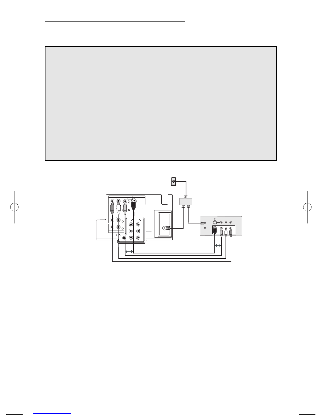
1) Connect the antenna or cable TV wire from the wall outlet, in to the RF Input of the two-way
splitter.
2) Connect an RF cable from the one of the RF Outputs on the splitter, in to the RF Input on
the back of the VCR.
3) Connect an RF cable from the other the RF Output on the splitter, in to the RF Input on the
back of the TV.
4) Connect the yellow video cable out from the VCR’s Video Output, in to the TV’s Video Input
jack, OR connect an S-Video cable from the VCR’s S-Video output, to the TV’s S-Video
input.
5) Connect the white audio cable out from the VCR’s Left Audio Output, in to the TV’s Left
Audio Input Jack.
6) Connect the red audio cable out from the VCR’s Right Audio Output, in to the TV’s Right
Audio Input jack.
• If your VCR is a mono sound unit, it will have only one Audio Out jack. Connect it to the
TV’s Left Audio Input.
• Please consult your VCR’s owner’s manual for more information on its operation.
There are three basic types of antenna or cable connections:
• If you have an antenna or have a cable system that does not require you use a cable box
to select channels, please refer to Diagram #1.
• If you have a cable system that requires the use of a cable box to access all the channels,
please refer to Diagram #2. If you cannot operate your Picture-In-Picture function using
Diagram #2, try the connection shown in Diagram #3. It is possible your cable box allows
the signal of only one channel at a time to be sent to your television.
• If you have a cable system that requires the use of a cable box to access certain premium
channels, but not “basic” cable channels, please refer to Diagram #3.
• For your convenience, connection to a VCR is also shown in the following diagrams. A
VCR is not necessary for operation of the television or Picture-In-Picture (PIP) function.You may omit the VCR from your connections if you wish.
• For instructions on connecting a VCR only, please see the Quick Setup on page 11.
• For information on using PIP, please see page 47.
• The PIP feature is available on models AV-36F803, AV-32F803 and AV-27F803 only.
Cable and VCR Connections
13
Diagram #1
Illustration of AV-27F803
R
R
R
AUDIO OUT
AV COMPULINK
AUDIO
AUDIO
L MONO
L MONO
L
INPUT 4
S VIDEOVIDEO
OVER
COMPONENT
VIDEO
OR
INPUT 1
INPUT 2
COMPONENT
VIDEO
Y
P
B
P
R
CABLE or ANTENNA
OUT
OUT OUT
75Ω
(VHF / UHF)
IN
TWO-WAY
SPLITTER
IN
OUT
VCR
VLR
OR
Page 14
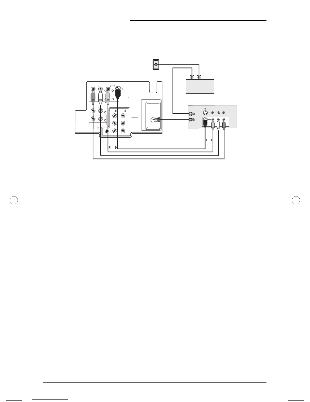
Illustration of AV-27F803
Connections
14
1) Connect the antenna or cable TV wire from the wall outlet, in to the RF Input of the cable
box.
2) Connect an RF cable from the RF Output of the cable box, in to the RF Input on the back of
the VCR.
3) Connect an RF cable from the RF Output of the VCR, in to the RF Input on the back of the
TV.
4) Connect the yellow video cable out from the VCR’s Video Output, in to the TV’s Video Input
jack, OR connect an S-Video cable from the VCR’s S-Video output, to the TV’s S-Video
input.
5) Connect the white audio cable out from the VCR’s Left Audio Output, in to the TV’s Left
Audio Input Jack.
6) Connect the red audio cable out from the VCR’s Right Audio Output, in to the TV’s Right
Audio Input jack.
• Please see page 47 for information on using the PIP feature with a Cable Box.
• If your VCR is a mono sound unit, it will have only one Audio Out jack. Connect it to the TV’s
Left Audio Input.
• Please consult your VCR’s owner’s manual for more information on its operation.
Cable and VCR Connections - Continued
Diagram #2
R
R
R
AUDIO OUT
AV COMPULINK
AUDIO
AUDIO
L MONO
INPUT 4
L MONO
L
S VIDEOVIDEO
OVER
COMPONENT
VIDEO
INPUT 1
INPUT 2
COMPONENT
VIDEO
CABLE or ANTENNA
OUT
75Ω
(VHF / UHF)
Y
P
B
P
R
OUT IN
Cable Box
IN
OUT
VCR
VLR
OR
OR
Page 15

Illustration of AV-27F803
Connections
15
The connection diagrams are intended to show some basic general connections.
Some cable companies may require special connections to properly use your television or 2-tuner PIP function. If you follow these diagrams and either the television or
PIP does not work properly, contact your local cable operator for more connection
information. Please see page 47 for more information on the PIP feature.
Cable and VCR Connections - Continued
1) Connect the antenna or cable TV wire from the wall outlet, in to the RF Input of the two-way
splitter.
2) Connect an RF cable from the one of the RF Outputs on the splitter, in to the cable box RF
Input.
3) Connect an RF cable from the Cable Box Output, in to the VCR RF Input.
4) Connect an RF cable from the other the RF Output on the splitter, in to the RF Input on the
back of the TV.
5) Connect the yellow video cable out from the VCR’s Video Output, in to the TV’s Video Input
jack, OR connect an S-Video cable from the VCR’s S-Video output, to the TV’s S-Video input.
6) Connect the white audio cable out from the VCR’s Left Audio Output, in to the TV’s Left Audio
Input jack.
7) Connect the red audio cable out from the VCR’s Right Audio Output, in to the TV’s Right Audio
Input jack.
• Please see page 47 for information on using the PIP feature with a Cable Box.
• If your VCR is a mono sound unit, it will have only one Audio Out jack. Connect it to the
TV’s Left Audio Input.
• Please consult your VCR’s owner’s manual for more information on its operation.
Diagram #3
WALL
CABLE or ANTENNA
OUT
IN
TWO-WAY
SPLITTER
OUT OUT
R
R
R
AUDIO OUT
AV COMPULINK
AUDIO
AUDIO
L MONO
INPUT 4
L MONO
L
S VIDEOVIDEO
OVER
COMPONENT
VIDEO
INPUT 1
INPUT 2
COMPONENT
VIDEO
75Ω
(VHF / UHF)
Y
P
B
P
R
OUT IN
CABLE BOX
IN
OUT
VCR
VLR
OR
OR
Page 16

Connections
16
1) Connect Green cable out from DVD player “Y” Component Output, in to TV “Y” Component
Input.
2) Connect Blue cable out from DVD player “P
B” Component Output, in to TV “PB” Component
Input.
3) Connect Red cable out from DVD Player “PR” Component Output, in to TV “PR” Component
Input.
4) Connect White Audio cable out from DVD Left Audio Output, in to TV Left Audio Input 2.
5) Connect Red Audio cable out from DVD Right Audio Output, in to TV Right Audio Input 2.
• Green, blue and red are the most common colors for DVD cables. Some models may vary
colors, please consult the user’s manual for your DVD Player for more information.
• Be careful not to confuse the red DVD cable with the red audio cable. It is best to complete
one set of connections (DVD or Audio Output) before starting the other to avoid accidentally
switching the cables.
• See page 22 for instructions on programming your remote control to operate the basic func-
tions of your DVD player.
• AV-36F803, AV-32F803 & AV-27F803: You may also connect the DVD player to Input 4.
• AV-36F703, AV-32F703, AV-27F703, AV-36F713, AV-32F713, and AV-27F713: If you use
Input 2 (Component-In) for the DVD connection, you must set the V2 COMPONENT-IN on
the initial Setup Menu to “YES” for proper display of the DVD signal.
NOTE: Progressive DVD Players (players with an output scan of 31.5 KHz) will not work prop-
erly with this television.
Connecting to a DVD player
Illustration of AV-27F803
L MONO
INPUT 4
L MONO
OVER
COMPONENT
VIDEO
S VIDEOVIDEO
INPUT 1
INPUT 2
COMPONENT
VIDEO
AUDIO OUT
R L
75Ω
(VHF / UHF)
Y
P
B
P
R
DVD PLAYER
Y
Green
PB
Blue
PR
Red
OUT
R
R
R
AUDIO OUT
AV COMPULINK
AUDIO
AUDIO
L
Page 17

Illustration of AV-27F803
Connections
17
1) Connect the yellow video cable out from the Camcorder’s Video Output, in to the TV’s Video
Input jack.
2) Connect the white audio cable out from the Camcorder’s Left Audio Output, in to the TV’s
Left Audio Input Jack.
3) Connect the red audio cable out from the Camcorder’s Right Audio Output, in to the TV’s
Right Audio Input Jack.
• If your Camcorder is a mono sound model it will have only one audio jack. Connect it to the
TV’s Left Audio Jack.
Connecting to an External Amplifier
Connecting to a Camcorder
1) Connect the white audio cable from the TV’s Left Audio Output jack to the Amplifier’s Left
Audio Input jack.
2) Connect the red audio cable from the TV’s Right Audio Output jack to the Amplifier’s Right
Audio Input jack.
You may connect a camcorder to your television by using the front Input Jacks (Input 3)
located under the front panel door. To access, press lightly on the door to open it. You may
also connect a game console or other equipment using these jacks. Camcorders may also be
connected to the television’s rear input jacks.
Illustration of AV-27F803
RIGHT FRONT
SPEAKER
R
R
R
AUDIO OUT
AV COMPULINK
AUDIO
AUDIO
L MONO
INPUT 4
L MONO
L
S VIDEOVIDEO
OVER
COMPONENT
VIDEO
INPUT 1
INPUT 2
COMPONENT
VIDEO
LEFT FRONT
SPEAKER
AMPLIFIER
75Ω
(VHF / UHF)
Y
P
B
P
R
VIDEO
INPUT 3
L MONO
AUDIO R
MENU
CHANNEL
OPERATE
VOLUME
ON TIMER
CAMCORDER
POWER
Page 18

Connections
18
To Connect: Plug one end of the AV Compu Link cable into the AV Compu Link input on your
VCR, DVD, or other Compu Link device. Plug the other end of the AV Compu Link cable into
the AV Compu Link input at the rear of the television.
Connecting to JVC AV Compu Link
JVC’s AV Compu Link feature makes playing video tapes or DVDs totally automatic. Simply
insert a pre-recorded tape* into your JVC-brand VCR or DVD into your JVC DVD player and
the device will automatically turn on and begin playback. At the same time, using the
AV- CompuLink, the VCR or DVD player sends a signal to the television telling it to turn on
and switch to the proper video input
• The AV Compu Link cable may be included with the JVC AV Compu Link accessory you
wish to connect.If it is not, contact an authorized JVC Service Center for
part # EWP 805-012.
• AV Compu Link can only be used with JVC-brand products.
NOTES:
• In order for the VCR playback to begin automatically, the recording tabs must be removed
from the VHS tape. If the tab is in place, automatic switching will occur when you push the
VCR’s P
LAY button.
• The AV Compu Link cable has a male 3.5 mm (mono) plug on each end.
• If your JVC-brand VCR has “A Code/B Code Remote Control Switching” (see your VCR’s
instruction book), using VCR A Code will switch the TV to input 1.
•To connect a JVC HiFi receiver or amplifier for a completely automated home theater, see
the HiFi’s connection instructions for detailed connection information.
•AVCOMPU LINK III is compatible with select AV CompuLink receivers.
Illustration of AV-27F803
R
R
R
AUDIO OUT
AV COMPULINK
AUDIO
AUDIO
L MONO
INPUT 4
L MONO
L
S VIDEOVIDEO
OVER
COMPONENT
VIDEO
INPUT 1
INPUT 2
COMPONENT
VIDEO
75Ω
(VHF / UHF)
Y
P
B
P
R
AV Compu Link III compatible
VCR or DVD Player
AV
Compu
Link III
Swap
Page 19

Remote Control
• Before you can operate the remote control, you must first
install the batteries (included). See “Changing the Batteries”
at the bottom of this page for instructions. (For an illustration,
please see page 10.)
• Press the P
OWER button to turn the television on or off.
• Make sure the TV/CATV switch is set to TV. Move the switch
to CATV only if you need to operate a cable box.
• Slide the VCR/DVD selector switch to VCR to control a VCR,
slide to DVD to control a DVD player. Please see pages 20
to 22 for instructions on programming your remote control to
operate a Cable box, VCR or DVD player.
• Press the CH+ and CH- buttons to scan through the channels. Tap the CH+ or CH- button to move through the channels one channel at a time.
• To move rapidly through the channels using JVC’s
Hyperscan feature, press and hold CH+ or CH-. The channels will zip by at a rate of five channels per second.
• Press V
OL+or VOL - to raise or lower the volume. An indica-
tor bar will appear onscreen to show you the television volume level.
• The CH+/- and V
OL+/- buttons are also used to navigate
JVC’s onscreen menu system.
• You can directly access specific channels using the 10-key
pad.
• For more information on remote control button features, see
pages 43 to 46. For information on using the onscreen
menus, see page 24.
Changing the Batteries
Push down on the remote’s back cover and slide towards the bottom to remove it.
Insert two AA batteries (supplied), carefully noting the "+" and "–" markings on the batteries
and on the remote control. To avoid a potential short circuit, insert the "–" end first. Be sure to
use only size AA batteries.
When batteries are installed, slide the cover back into place (until it clicks into position).
• If the remote control acts erratically, replace the batteries. Typical battery life is six months to
one year. We recommend using alkaline batteries for longer battery life.
When you change the batteries, try to complete the task within three minutes. If you take
longer than three minutes, the remote control codes for your VCR, DVD, and/or Cable
Box may have to be reset (see page 20-22).
Remote Control Basics
Notes: Remote control model RM-C325G is shown at the left.
A different model remote control may have come with your
television.
19
16:9
TV
EZ SURF
INPUT
DISPLAY
SLEEP TIMER
HYPER SUR.
VIDEO STATUS
THEATER PRO
RM-C325G
MUTING
MENU
VCR CHANNEL
OPEN/CLOSE STILL/PAUSE
DVD
CATV
VCR
CHANNEL
SOURCE
100+
BBE
VOL
PREV NEXT
PLAY FFREW
REC STOP
1
4
7
CH
CH
+
POWER
MODE
PIP
ON/MOVE
FREEZE
SWAP
2
5
8
0
RETURN+
LIGHT
V CHIP
VOL
+
EXIT
PIP OFF
VCR/DVD
POWER
TV/VCR
PAUSE
3
6
9
TV
Page 20

Remote Programming
Setting the CATV, VCR and DVD Codes
You can program your remote to operate your cable box, satellite receiver, VCR or DVD
player by using the instructions and codes listed below. If the equipment does not respond to
any of the codes listed below or to the code search function, use the remote control supplied
by the manufacturer.
Cable Box or Satellite codes
The remote control is programmed with CATV and/or Satellite codes for power on, power off,
channel up, channel down, and 10 key operation.
1) Find the CATV/Satellite brand from the list of codes shown below.
2) Slide the 2-way selector switch to “CATV”.
3) Press and hold down the D
ISPLAY button.
4) With the D
ISPLAY button held down, enter the first code number listed using the 10 key pad.
5) Release the DISPLAY button.
6) Confirm the operation of the Cable Box/Satellite receiver.
• If your CATV or Satellite box does not respond to the first code, try the others listed. If it does
not respond to any code, try the Search Codes Function, on page 49.
20
Cable Box CODES
ABC
Archer
Cableview
Citizen
Curtis
Diamond
Eagle
Eastern
GC Brand
Gemini
General Instrument
Hamlin
Hitachi
Jerrold
Macom
Magnavox
Memorex
Movietime
Oak
Panasonic
Paragon
Philips
Pioneer
Pulsar
024
032, 025
051, 032
022, 051
058, 059
024, 032, 025
029
034
032, 051
022, 043
065, 024, 025,
026, 027, 020,
021, 022, 057,
023
040, 041, 042,
045, 058, 064
049, 024
065, 024, 025,
026, 027, 020,
021, 022, 057,
023
049, 050, 051,
054
033
030
032, 051
039, 037, 048
055, 056, 060,
071, 073
063
028, 029, 030,
052, 053, 031,
069
047, 062
051, 032
Cable Box CODES
Puser
RCA
Realistic
Regal
Regency
Rembrandt
Samsung
Scientific Atlanta
SLMark
Sprucer
Stargate
Telecaption
Teleview
Texscan
Tocom
Toshiba
Unika
Universal
Videoway
Viewstar
Zenith
Zenith/Drake
Satellite
032
061, 070
032
058, 064, 040,
041, 042, 045,
068
034
037, 032, 051,
038
051
057, 058, 059
051, 047
051, 056
032, 051
067
047, 051
044
035, 036, 066
050
032, 025
022, 032
052
029, 030
063, 046
046
Digital
Satellite
Systems
Echostar
Express VU
G.E.
G.I.
Gradiente
Hitachi
HNS (Hughes)
Panasonic
Philips
Primestar
Proscan
RCA
Sony
Star Choice
Toshiba
Uniden
CODES
100, 113, 114,
115
100, 113
106
108
112
104, 111
104
105
102, 103
108
106, 109, 110
106, 109, 110
107
104, 108
101
102, 103
Page 21

Remote Programming
VCR codes
The remote control is programmed with VCR codes for power on, power off, play, stop, fast-forward, rewind, pause, record, channel up, and channel down operation.
1) Find the VCR brand from the list of codes shown below.
2) Slide the first 2-way selector switch to “TV” and the other 2-way selector switch to “VCR”.
3) Press and hold down the D
ISPLAY
button.
4) With the D
ISPLAY button held down, enter the first code number listed with the 10 key pad.
5) Release the D
ISPLAY button.
6) Confirm the operation of the VCR.
• If your VCR does not respond to the first code, try the others listed. If it does not respond to
any code, try the Search Codes Function, on page 49.
• Some manufacturer’s VCR’s may not respond to the TV/VCR button, even if other buttons
work properly.
• To record, hold down the R
EC button on the remote and press PLAY.
21
VCRs CODES
Admiral
Aiwa
Akai
Audio Dynamic
Bell & Howell
Broksonic
Canon
CCE
Citizen
Craig
Curtis Mathes
Daewoo
DBX
Dimensia
Emerson
Fisher
Funai
G.E.
Go Video
Goldstar
Gradiente
Hitachi
Instant Replay
Jensen
JVC
Kenwood
LXI 027, 064, 058,
Magnavox
035
027, 032, 095
029, 072, 073,
074
003, 005
063, 071
020, 026, 094
023, 025
043
064
063, 029, 064
045, 024, 027,
093
043, 059, 024,
092
003, 004, 005
045, 093
043, 026, 077,
061, 025, 042,
020, 076
063, 066, 067,
065, 071, 091
027, 026, 020,
000
033, 045, 024
037, 051, 049,
050, 089
064
083, 084, 081,
000, 001
023, 045, 058,
027, 081, 093
024, 023
003
000, 001, 002,
003, 004, 005
003, 004, 064,
005
065, 066, 063,
067
031, 023, 024,
086
VCRs CODES
Marantz
Marta
Memorex
MGA
Minolta
Mitsubishi
Multitech
NEC
Olympic
Optimus
Orion
Panasonic
Penney
Pentax
Philco
Philips
Pioneer
Proscan
Quasar
Radio Shack
RCA
Realistic 024, 063, 036,
003, 004, 005
064
024, 067
038, 040, 047,
048, 041, 042
058, 045, 093
038, 040, 047,
048, 041, 042,
078, 090
047, 027, 062
003, 004, 005,
000
024, 023
028, 021, 035,
064
026, 020
023, 024, 021,
022
024, 058, 045,
063, 003, 004,
005, 093
058, 005, 045,
093
031, 024, 027,
023, 026, 020,
043
031, 023, 024,
086
023
045, 058, 023,
024, 031, 046,
059, 060, 033,
087, 093
021, 022, 023,
024
033, 024, 063,
036, 067, 040,
027
033, 045, 058,
023, 024, 031,
046, 059, 060,
083, 084, 085,
087, 093
067, 040, 027
VCRs CODES
Samsung
Samtron
Sansui
Sanyo
Scott
Sears
Shintom
Sharp
Signature 2000
Singer
Sony
SV 2000
Sylvania
Symphonic
Tashiro
Tatung
Teac
Technics
Teknika
Toshiba
Vector Research
Wards
Yamaha
Zenith 044, 082, 064,
037, 060, 062,
033, 089
089
003, 026, 020,
052
063, 067, 091,
071
059, 060, 062,
067, 038, 040,
047, 048, 026,
020
063, 064, 065,
066, 058, 000,
001
075
035, 036, 080,
088
027, 035
075
028, 029, 030,
053, 054, 055
027
031, 023, 024,
027
027, 081
064
003, 004, 005
003, 004, 027,
005
021, 022, 023,
024
024, 027, 070
059, 046, 079
005
035, 036, 067,
044, 064
063, 003, 004,
005
094
Page 22

Remote Programming
22
DVD codes
The remote control is programmed with DVD codes for power on, power off, play, stop,
fast-forward, rewind, previous chapter, next chapter, tray open/close, and still/pause operation.
1) Find the DVD player brand from the list of codes shown below.
2) Slide the first 2-way selector switch to “TV” and the other 2-way selector switch to “DVD”.
3) Press and hold down the D
ISPLAY button.
4) With the DISPLAY
button held down, enter the first code number listed with the 10 key pad.
5) Release the D
ISPLAY button.
6) Confirm the operation of the DVD player.
• If your DVD player does not respond to the first code, try the others listed. If it does not
respond to any code, try the Search Codes Function, on page 49.
• After you program your remote, some DVD buttons may not work properly. If some buttons do
not work properly, use the remote control which came with your DVD player.
DVD Player CODES
Aiwa
Apex
Denon
Hitachi
JVC
Kenwood
Konka
Mitsubishi
Onkyo
Oritron
Panasonic
Philips
Pioneer
Raite
043
040
020, 037
030, 031
000
035
039
025
041
044
020
023, 036
022
033
DVD Player CODES
RCA
Sampo
Samsung
Sharp
Silvania
Sony
Te chnics
To shiba
Vialta 050
Wave
Yamaha
Zenith
021, 026
034
030
028
038
024, 045, 046,
047
020
023
042
020
027, 032
Page 23

To bring up the onscreen menu, press the MENU button on the remote control. The item that
appears in yellow is the one currently selected. If you press the M
ENU button again, the
onscreen display will skip to the next menu screen. If you use the Menu button on the TV’s front
panel instead of the remote, an additional menu screen showing channel number and input will
appear. The “Plug In Menu” will appear the first time the TV is plugged in.
Notes: Menus shown in this book are illustrations, not exact replications of the television’s
onscreen displays.
Onscreen Menus
23
Using the Guide
The Onscreen Menus
Certain symbols are used throughout this guide to help you learn about the features of your
new television. The ones you will see most frequently are:
Up and Down arrows mean press the C
H+ or CH-buttons. Pressing the CH+ or CH- but-
tons let you:
• Move vertically in a main menu screen
• Move through a submenu screen
• Move to the next letter, number, or other choice in a submenu
• Back up to correct an error
• Scan through TV channels (when not in a menu screen)
¥
Left and right arrows mean press the V
OLUME+ or VOLUME-buttons to move left or right
to:
• Select a highlighted menu item
• Select an item in a submenu
• Select numbers in certain menu options
• Turn the volume up or down (when not in a menu screen)
The “Press Button” icon means you should press the button named on your remote control. (Button names appear in S
MALL CAPITAL LETTERS.)
The “Helping Hand” icon points to the highlighted or selected item in a menu.
Page 24

Onscreen Menus
24
The Onscreen Menu System
Your television comes with JVC’s Onscreen Menu System. The Onscreen Menus let you make
adjustments to your television’s operation simply and quickly. Examples of the Onscreen Menus
are shown below and on the next page. Detailed explanations on using each menu follow later
in this guide.
Press the M
ENU button
INITIAL SETUP 01
INITIAL SETUP 02
PICTURE ADJUST 01
PICTURE ADJUST 02
SOUND ADJUST
CLOCK/TIMERS
• “PURITY” is only for models AV-36F803, AV-36F713 and AV-36F703.
Page 25

Plug In Menu
The Plug In Menu comes up automatically when you first turn on the TV after plugging it in. The
Plug In Menu helps you to get your TV ready to use by letting you set your preferences for:
• The Language in which you want the onscreen menus to appear,
• The Auto Tuner Setup of which channels you wish to receive,
• Setting the TV’s clock to the correct time so your timer functions will work properly.
Descriptions of each of the Plug In Menu features appear on this page and the next. We recommend you complete the Plug In Menu setup first so your TV is set up just the way you want,
right away.
Introduction
Auto Tuner Setup
Language
You can choose to view your onscreen menus in three languages: English (ENG.), French
(FRAN.), or Spanish (ESP.).
Press the MENU button
To LANGUAGE
¥
To choose a language
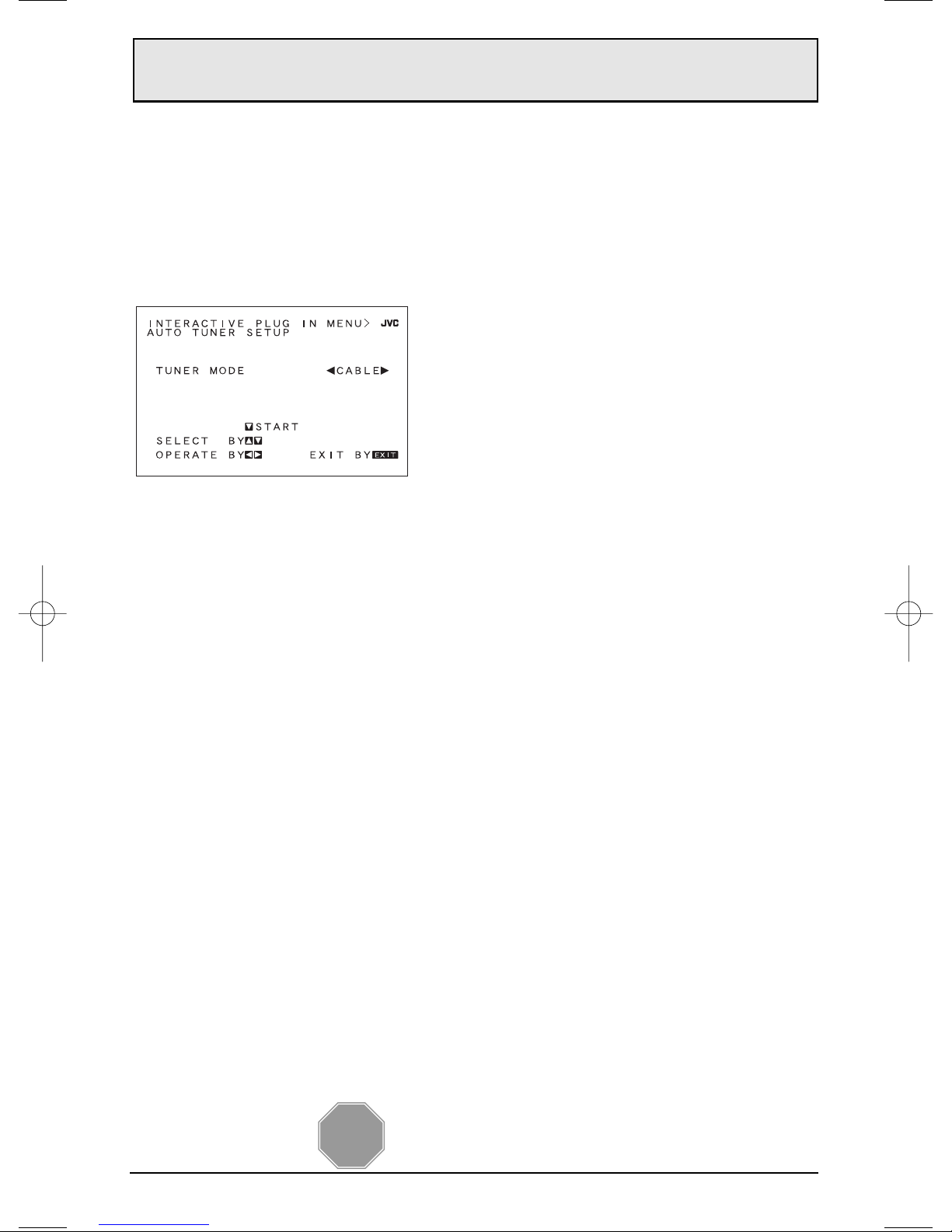
In Auto Tuner Setup, the TV automatically scans through all available channels, memorizing the
active ones and skipping over blank ones or channels with weak signals. This means when you
scan (using the C
HANNEL +/- buttons) you will receive only clear, active channels.
Press the MENU button
To AUTO TUNER SETUP
¥
To operate
¥
To choose CABLE or AIR (or SKIP)
To m o ve to START
¥
To start Auto Tuner Setup
• Noise Muting will not work during Auto Tuner Setup.
• You will not need to press the MENU button to enter this screen from the Plug In Menu.
• SKIP appears only for Plug in Menu.
NOW
PROGRAMMING !
PROGRAMMING OVER!
48
Programming will take approximately 1 to 2
minutes.
• You will not need to press the M
ENU button to enter this screen from the Plug In Menu.
25
ENG. FRAN.
ESP.
Page 26

Plug In Menu
26
Auto Clock Set
Before you use any of your TV’s timer functions, you must first set the clock. You may precisely
set your clock using the XDS time signal broadcast by most Public Broadcasting stations. To
set the clock using the XDS signal:
Enter the channel number of your local PBS station
Press M
ENU
To SET CLOCK
¥
To operate
¥
To A U TO
To TIME ZONE
¥
To select your time zone
To move to Daylight Savings Time (D.S.T.)
¥
To turn D.S.T. ON or OFF
To FINISH
¥
To save settings and exit
• If you do not have a PBS station in your local area, you will have to set the clock manually.
See ‘Manual Clock Set’ on the next page for instructions.
• The Daylight Savings Time feature automatically adjusts your TV’s clock for Daylight Savings.
The clock will move forward one hour at 2:00 am on the first Sunday in April. The clock will
move back one hour at 2:00 am on the last Sunday in October.
• You will not need to press the MENU button to enter this screen from the Plug In Menu.
ATLANTIC
HAWAII
EASTERN
ALASKA
CENTRAL
MOUNTAIN
PA CIFIC
Page 27

Plug In Menu
27
Manual Clock Set
NOTE:
You will have to reset the clock after a power interruption. You must set the clock before operating any timer functions.
To set your clock manually (without using the XDS signal), choose MANUAL from the Set Clock
menu and follow the steps below.
To SET CLOCK
¥
To operate
¥
To MANUAL
To move to the hour
¥
To set the hour
To move to minutes
¥
To set the minutes
To move to START CLOCK
¥
To start clock and exit
• You will not need to press the M
ENU button to enter this screen from the Plug In Menu.
THANK YOU!
Page 28
Channel Summary
Channel Summary
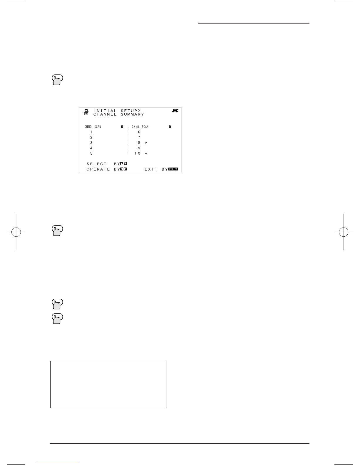
Channel Summary allows you to customize the line-up of channels received by your TV.You
can add or delete channels from the line-up or prevent any unauthorized viewers from watching
any or all 181 channels.
Press the M
ENU button
To CHANNEL SUMMARY
¥
To operate
The Channel Summary screen (above) will now be displayed with the channels set to scan
marked with an "". You can delete channels from the scan by removing the "". If any chan-
nels were missed during Auto Tuner Setup and you wish to add them, you may by placing an
""next to the channel number.
To the SCAN column
¥
To include or delete from scan
E
XIT when finished
You can block access to a channel by activating the Channel Lock.
To CHANNEL SUMMARY
¥
To operate
To the Lock Column
ZERO to lock or unlock that channel
E
XIT when finished
Channel Guard Message
When a viewer attempts to watch a guarded channel, the following message appears:
To watch a channel that you have locked, enter the Lock Code using the 10 key pad.
If the wrong code is entered, the message
“INVALID LOCK CODE!” will flash on the screen:
The channel cannot be accessed until the
correct code is entered.
• Once a channel has been unlocked, it will
remain unlocked until the television is turned
off.
• See also “Set Lock Code”, page 36.
THIS CHANNEL IS LOCKED BY
CHANNEL GUARD.
PLEASE ENTER LOCK CODE BY
10 KEY PAD TO UNLOCK IT.
NO. - - - -
28
Page 29

29
V-Chip
Your TV is equipped with V-Chip technology which enables TV Parental Guidelines (for United
States and Canada) and Movie (MPAA) Guideline controls. V-Chip technology allows you to
program your TV to receive, or not to receive, programs based on content according to the
guidelines. Programs which exceed the ratings limits you set will be blocked. When a viewer
attempts to watch a blocked channel, this message appears:
The channel will remain blocked until the correct lock code is entered (see page 36 for information on setting your lock code).
You can customize the V-Chip settings of your television to match your personal tastes. The
V-Chip menu below is the starting point for your V-Chip settings
You can use US V-Chip settings (for programming broadcast from the United States), Canadian
V-Chip settings (for programming broadcast from Canada), and movie ratings. You may use any
or all of the settings (US V-Chip, Canada V-Chip, Movie ratings). Descriptions for setting each of
the three V-Chip formats appear in the next seven pages along with descriptions of the rating
categories.
To access the rating categories:
THIS PROGRAMMING EXCEEDS
YOUR RATING LIMITS.
PLEASE ENTER LOCK CODE BY
10 KEY PAD TO UNLOCK IT.
NO. - - - -
Special Note about Ratings
Some programs are not broadcast with a ratings signal. Therefore, even if you setup V-Chip
ratings limits, these programs will not be blocked. Parents are cautioned to preview the con-
tents of these programs or movies.
Press the MENU button
To V -CHIP
¥
To operate (Lock icon will appear)
Press Z
ERO to access the V-Chip menu
¥
To turn V-Chip ON or OFF (V-Chip must be turned ON for rating settings to operate)
To move to SET US TV RATINGS, SET MOVIE RATINGS, or SET CANADIAN RATINGS (see following pages for descriptions of each item)
Page 30

30
V-Chip
US V-Chip Ratings
U.S. PARENTAL RATING SYSTEMS
Programs with the following ratings are appropriate for children.
❒ TV Y is Appropriate for All Children.
Programs are created for very young viewers and should be suitable for all ages, including
children ages 2 - 6.
❒ TV Y7 is for Older Children.
Most parents would find such programs suitable for children 7 and above. These programs
may contain some mild fantasy violence or comedic violence, which children should be able
to discern from reality.
Programs with the following ratings are designed for the entire audience.
❒ TV G stands for General Audience.
Most parents would find these programs suitable for all age groups. They contain little or no
violence, no strong language, and little or no sexual dialog or situations.
❒ TV PG Parental Guidance Suggested.
May contain some, but not much, strong language, limited violence, and some suggestive
sexual dialog or situations. It is recommended that parents watch these programs first, or
with their children.
❒ TV 14 Parents Strongly Cautioned.
Programs contain some material that may be unsuitable for children under the age of 14
including possible intense violence, sexual situations, strong coarse language, or intensely
suggestive dialog. Parents are cautioned against unattended viewing by children under 14.
❒ TV MA Mature Audiences Only.
These programs are specifically for adults and may be unsuitable for anyone under 17 years
of age. TV MA programs may have extensive V, S, L, or D.
Viewing Guidelines
In addition to the ratings categories explained above, information on specific kinds of content
are also supplied with the V-Chip rating. These types of content may also be blocked. The
content types are:
• V/FV is for VIOLENCE/FANTASY VIOLENCE
• S stands for SEXUAL CONTENT
• L stands for strong LANGUAGE
• D stands for suggestive DIALOG
Page 31

V-Chip
31
Line up the cursor in the column (TV PG, TV G, etc.) with the content row (V/FV, S, etc.) and
press the
or
to move the cursor to the correct location. Press ¥or to turn the locking
feature on or off. An item is locked if the icon appears instead of a “—”.
For example. To b lock viewing of all TV 14 shows, move the cursor to the top row of that
column and add a lock icon. Once you've put a lock on the top row, everything in that column is
automatically locked.
To the TV 14 Column
¥
To turn on the lock
To FINISH
¥
To save settings and exit
• If you want to change the setup, move the cursor to the top column and change the lock icon
to “—” by pressing
¥
or again. You may then select individual categories to block.
Press the MENU
button
To V -CHIP
¥
To operate (Lock icon appears)
Press Z
ERO to access the V-Chip menu
¥
To turn V-Chip ON or OFF
To move to SET US TV RATINGS
¥
To operate
Setting US V-Chip Ratings
Directions to set US V-Chip Ratings:
INITIAL SETUP V-CHIP
SET US TV RATINGS
TV
TV
MA
V/FV
S
L
D
SELECT BY
OPERATE BY
14
FINISH
TVY7TV
TVGTV
PG
EXIT BY
Y
EXIT
Page 32

V-Chip
32
Setting ratings with the V-Chip button
Example 2:
If you want to set your V-Chip settings to block all programming above a current setting such as
TV PG-V (with violence):
Press Z
ERO when TV-PG - V is displayed
All Programming above TV-PG - V (with Violence) will be blocked.
To access Rating information about a certain program, press the V-CHIP button while viewing
that program. A display like this will appear:
If you decide you want to block this category of viewing, press "0" while the above screen is
visible, and all programs from that category will be blocked.
Example 1:
If you want to set your V-Chip settings to block all programming above TV-PG:
Press Z
ERO when TV-PG is displayed
All Programming above TV-PG will be blocked.
• For Children's programming you can block TV-Y and Y7 programs by Pressing “0” when Y is
displayed during a program. Programming for audiences other than children’s audiences will
not be affected.
PROGRAM IS RATED :
TV-PG - V
INITIAL SETUP V-CHIP
SET US TV RATINGS
V/FV
S
L
D
SELECT BY
OPERATE BY
TV
MA
TV
TV
PG
14
TV
G
TVY7TV
EXIT BY
Y
EXIT
INITIAL SETUP V-CHIP
SET US TV RATINGS
V/FV
S
L
D
TV
MA
TV
TV
PG
14
TVY7TV
TV
G
Y
SELECT BY
OPERATE BY
EXIT BY
EXIT
Page 33

V-Chip
❒ NR - Not Rated.
This is a film which has no rating. In many cases these films were imported from countries
which do not use the MPAA ratings system. Other NR films may be from amateur producers
who didn’t intend to have their film widely released.
NR (Not Rated) Programming may contain all types of programming including children's programming, foreign programs, or adult material.
❒ G – General Audience.
In the opinion of the review board, these films contain nothing in the way of sexual content,
violence, or language that would be unsuitable for audiences of any age.
❒ PG – Parental Guidance.
Parental Guidance means the movie may contain some contents such as mild violence,
some brief nudity, and strong language. The contents are not deemed intense.
❒ PG-13 – Parents Strongly Cautioned.
Parents with children under 13 are cautioned that the content of movies with this rating may
include more explicit sexual, language, and violence content than movies rated PG.
❒ R - Restricted.
These films contain material that is explicit in nature and is not recommended for
unsupervised children under the age of 17.
❒ NC-17 - No One Under 17.
These movies contain content which most parents would feel is too adult for their children to
view. Content can consist of strong language, nudity, violence, and suggestive or explicit
subject matter.
❒ X - No One under 18.
Inappropriate material for anyone under 18.
Movie Ratings
Press the MENU button
To V -CHIP
¥
To operate (Lock icon appears)
Press Z
ERO to access V-Chip setup options
To SET MOVIE RATINGS
¥
To enter movies menu
For example, to block viewing of X and NC-17 rated from shows:
To the X Column
¥
To turn on the lock
To the NC-17 Column
¥
To turn on the lock
To FINISH
¥
To save settings and exit
Directions to set Movie (MPAA) Ratings:
33
Page 34

V-Chip
❒ E - Exempt.
Exempt programming includes: news, sports, documentaries and other information
programming, talk shows, music videos, and variety programming.
❒ C – Programming Intended for Children.
Violence Guidelines: There will be no realistic scenes of violence. Depictions of aggressive
behavior will be infrequent and limited to portrayals that are clearly imaginary, comedic or
unrealistic in nature.
❒ C8+ – Programming Intended for Children 8 and Over.
Violence Guidelines: Any realistic depictions of violence will be infrequent, discreet, of low
intensity and will show the consequences of the acts. There will be no offensive language,
nudity or sexual content.
❒ G – General Audience.
Programming will contain little violence and will be sensitive to themes which could affect
younger children.
❒ PG - Parental Guidance.
Programming intended for a general audience, but which may not be suitable for younger
children. Parents may consider some content not appropriate for children aged 8-13.
❒ 14+ - 14 Years and Older.
Parents are strongly cautioned to exercise discretion in permitting viewing by pre-teens and
early teens. Programming may contain mature themes and scenes of intense violence.
❒ 18+ - Adult.
Material intended for mature audiences only.
Canadian V-Chip Ratings
Directions to set Canadian V-Chip Ratings:
Press the MENU button
To V -CHIP
¥
To operate (Lock icon appears)
Press Z
ERO to access V-Chip setup options
To SET CANADIAN RATINGS ENG (for English)
¥
To enter ratings menu
For example, to block viewing of programming rated 14+ and 18+ :
To the 18+ Column
¥
To turn on the lock
To the 14+ Column
¥
To turn on the lock
To FINISH
¥
To save settings and exit
• For instructions on “Set Canadian Ratings FRE (in French)”, please see page 34 in the
French side of this user’s guide.
34
18+
14+
P
G
C
GC
8
Page 35

35
V-Chip
Unrated Programs
Notes About Unrated Programs:
Unrated programming refers to any programming which does not contain a rating signal.
Programming on television stations which do not broadcast rating signals will be placed in the
“Unrated Programming" category.
Examples of Unrated programs:
Emergency Bulletins
Locally Originated Programming
News
Political Programs
Public Service Announcements
Religious Programs
Sports
Weather
Some Commercials
• TV programs or movies that do not have rating signals will be blocked if the Unrated
Category is set to BLOCK.
Directions to Block Unrated Programs:
You can block programs that are not rated.
Press the MENU button
To V -CHIP
¥
To operate (The lock icon appears)
Press Z
ERO to access V-Chip setup options
To UNRATED
¥
To VIEW or BLOCK
Press E
XIT when done
Page 36

36
V-Chip
Set Lock Code
Channel Guard and V-Chip settings are protected by a four-digit Lock Code.Your TV comes
pre-set with a Lock Code of "0000". You may change the code to any four-digit number you
wish. To change the Lock Code, follow the steps below.
Press the MENU button
To SET LOCK CODE
¥
To operate (Lock icon appears)
Press Z
ERO to access the Lock Code
The first digit will be highlighted
¥
To select the number
To move to the next digit
Continue to follow these directions for all four numbers
To FINISH
¥
To save settings and exit
Your Lock Code is now set.
• After a power interruption you must reset the Lock Code.
• Write your Lock Code number down and keep it hidden from potential viewers.
• If you forget the Lock Code, a new code may be set using the steps listed above.
NOTES:
Page 37

37
Picture Settings
Tint
Color
Picture
Bright
Detail
Tint allows you to adjust the levels of red and green in your TV picture.
Press the MENU button
To TINT
To increase the levels of green
¥
To increase the levels of red
To move to the next setting
The color function lets you make all the colors in the TV picture appear either more vivid or
subtle.
Press the MENU button
To COLOR
To make the colors more vivid
¥
To make the colors more subdued
To move to the next setting
Picture allows you to adjust the levels of black and white on the TV screen, giving you a darker
or brighter picture overall.
Press the M
ENU button
To PICTURE
To increase the level of contrast
¥
To decrease the level of contrast
To move to the next setting
You can adjust the overall brightness of the TV picture with the Bright control.
Press the MENU button
To BRIGHT
To lighten the picture
¥
To darken the picture
To move to the next setting
The Detail feature adjusts the level of fine detail displayed in the picture.
Press the MENU button
To DETAIL
To make the picture sharper (more detail)
¥
To make the picture smoother (less detail)
To move to the next setting
Page 38

Picture Settings
38
Noise Muting
This feature inserts a blank blue screen over channels which are not broadcasting or are too
weak to be received clearly.
Press the M
ENU button
To NOISE MUTING
¥
To turn Noise Muting ON or OFF
• Noise Muting will not work during Auto Tuner Setup or
when you operate Channel Summary.
With COLOR TEMPERATURE, you can decide how strong or dull the colors appear on the TV
screen.
Press the M
ENU button
To COLOR TEMPERATURE
¥
To COLOR TEMPERATURE LOW or HIGH
Color Temperature
(VSM) Velocity Scan Modulation
Velocity Scan Modulation circuitry varies the electron beam's horizontal scanning speed to help
accentuate the differences in picture brightness to sharpen the edges of images.
Press the M
ENU button
To VSM
¥
To turn VSM ON or OFF
Page 39

39
Sound Settings
You can increase or decrease the level of low-frequency sound in the TV’s audio with the Bass
adjustment.
Press the M
ENU button
To BASS
To increase the bass
¥
To decrease the bass
To move to the next setting
Use Treble to adjust the level of high-frequency sound in your TV’s audio.
Press the M
ENU button
To TREBLE
To increase the treble
¥
To decrease the treble
To move to the next setting
Adjust the level of sound between the TV’s two speakers with the Balance setting.
Press the M
ENU button
To BALANCE
To shift the balance towards the right speaker
¥
To shift the balance towards the left speaker
To move to the next setting
MTS technology allows several audio signals to be broadcast at once, giving you a choice in
what you wish to hear with a TV program. In addition to mono or stereo sound, an MTS broadcast may also include a Second Audio Program (SAP)
.
Press the MENU button
To MTS
¥
Select the mode
(The ON AIR arrow tells you if a broadcast is in Stereo and/or contains an SAP).
• Keep the TV in STEREO mode to get the best sound quality. The sound will work in STEREO
mode even if a certain broadcast is in MONO sound only.
• Choose the MONO setting to reduce excessive noise on a certain channel or broadcast.
• Selecting SAP will allow you to hear an alternative soundtrack, if one is available.
MTS (Multi-Channel Television Sound)
Treble
Balance
Bass
You can leave the Sound Settings menu at any time by pressing the E
XIT button on the remote
control.
NOTE:
Page 40

40
General Items
The On/Off timer lets you program your television to turn itself on or off. You can use it as an
alarm to wake up, to help you remember important programs, or as a decoy when you're not
home.
Press the M
ENU button
To ON/OFF TIMER
¥
To operate (begins with ON TIME)
¥
To set the hour (AM/PM) you want the TV to turn on
To move to minutes
¥
To set the minutes
To accept ON TIME and move to OFF TIME (the time the TV will turn off). Set the
OFF TIME the same way as ON TIME
To accept OFF TIME and move to CHANNEL
¥
To select channel
To ON VOLUME
¥
To set the volume level
To m o ve to MODE
¥
Choose ONCE or EVERYDAY
To ON/OFF TIMER
¥
Choose ON to accept the timer setting, choose OFF if you don't wish to accept
To FINISH
¥
To save settings
On/Off Timer
On/Off Timer Note for PIP (AV-36F803, AV-32F803 & AV-27F803) only.
• The On/Off time cannot be set to locked or guarded channels.
• In order for the On/Off timer to work, the clock must be set.
• After a power interruption, the Timer settings must be reset.
NOTES:
If the television is on when a timed event is about to start a Timer Preview window will appear.
The Timer Preview window will appear in the lower right corner of the screen seven seconds
before the timer is programmed to begin. When the timer activates, the Preview picture will
become the main picture.
Page 41

General Items
Many broadcasts now include an onscreen display of dialog called Closed Captions. Some
broadcasts may also include displays of additional information in text form. Your television can
access and display this information using the Closed Caption feature. To activate the Closed
Caption feature, follow the steps below.
Press the M
ENU button
To CLOSED CAPTION
¥
To operate
¥
To select CAPTION (for Closed Captions), TEXT (for text display), or OFF (for no display)
To move to CAPTION or TEXT
¥
To select a caption (CC1 to CC4) or text channel (T1 to T4)
To accept that selection and move to FINISH
¥
To save settings and exit
Closed Caption
• Closed Caption subtitles are usually found on closed caption channel CC1. Some programs may
include additional text information which is usually found on text channel T1. The other channels
are available for future use.
• Closed captioning may not work correctly if the signal being received is weak or if you are playing a
video tape.
• Most broadcasts containing Closed Captioning will display a notice at the start of the program.
NOTES:
Front Panel Lock
This allows you to lock the keys on the front of the TV, so that a child may not accidentally
change your viewing preferences.
Press the MENU button
To FRONT PANEL LOCK
¥
To turn ON or OFF
E
XIT when finished
• Not only can you turn off this feature by using the remote control, you can turn it off by
unplugging your TV, and plugging it back in. This is in case the batteries die out or you acidentally lose your remote. Doing this will set this feature back to off. Also, if it is difficult to
unplug your TV, you can turn this feature off by pressing the M
ENU button on the front of the
TV for more than 3 seconds. In this case, the OSD for FRONT PANEL LOCK will appear.
You can also turn this feature off by pressing the POWER button on the TV for more
than 3 seconds.
41
Page 42

Get the best quality video from your DVD player by using this setting and the DVD inputs at the
rear of the television. Set either to YES for component input (for DVD) or to NO for composite
video input (for a regular VCR), using V2 COMPONENT-IN.
Press the M
ENU button
To V2 COMPONENT-IN
¥
To turn the input ON (YES) or OFF (NO)
E
XIT when finished
• This option should be used with DVD players only. For information on connecting VCR’s see
page 13. For more information on connecting a DVD player, see page 16.
V2 Component-In
General Items
42
Auto Shut Off
This function automatically shuts off your TV when there is no signal from the channel the TV
is on.
Press the MENU button
To AUTO SHUT OFF
¥
To turn ON or OFF
E
XIT
when finished
• If the channel that you have on does not recieve a signal for more than one minute, the blinking text “NOT RECIEVING A SIGNAL” appears on the screen. If no signal is being recieved
within 9 minutes, the TV shuts itself off.
XDS ID
XDS ID Display provides a channels call letters, the network’s name, and even a program
name.
Press the MENU button
To XDS ID
¥
To turn ON or OFF
E
XIT when finished
Purity (AV-36F803, AV-36F703, AV-36F713 only)
Sometimes, your television can be affected by the magnetic fields of the earth. If you notice
that there are sections of color on your TV screen that appear stained or blotchy, use this function to help eliminate it.
Press the M
ENU button
To PURITY
¥
To enter
¥
To adjust purity
N S
--------------------------
||
--------------------------
Page 43

Button Functions
43
The MENU button allows you to access JVC’s onscreen menu system. Press MENU to activate
the onscreen menu system.
• See individual topics (like “Sound Settings) for specific information on using menus.
Press the EXIT button to leave a menu screen. On the RM-C325G this button is also labeled
“PIP O
FF”. Press EXIT/PIP O
FF to turn off the Picture-in-Picture function (please see page 47 for
more information on the PIP feature).
• PIP is available on series F803 models only.
Menu
Exit and PIP Off
Display
• Please note that if the Clock, Sleep Timer or On/Off Timer are not set, the Display screen will
show: "CLOCK NOT SET", "SLEEP TIMER OFF", and "ON/OFF TIMER OFF" respectively.
NOTE:
The Display screen shows the current status of timers, inputs, and XDS ID.
Press the DISPLAY button
The screen above shows the following information:
• The current channel or AV input (Channel 05)
• The current time (12:20 pm)
• Sleep Timer status/minutes remaining (The Sleep Timer is off)
• On/Off Timer status (Set to turn on everyday at 7:00 PM, off at 10:00 PM)
• Each Press of the D
ISPLAY button changes the display mode:
Display - Full screen shown above
Time - Shows the current time only
Channel - Shows the current channel
Off - Turns Display off
• You may also turn off the Display at any step by pressing E
XIT.
05 KLVX PBS
SESAME STREET
NOW 12:20 PM
SLEEP TIMER OFF
ON/OFF TIMER EVERYDAY
ON TIME 7:00 PM
OFF TIME 10:00 PM
Display Time Channel
Off
Page 44

Button Functions
44
Video Status
Sleep Timer
Hyper Surround
Muting
The VIDEO STATUS button gives you a choice of three TV picture display settings, including a
display of your own preferences.
Standard - Resets the picture display to the factory settings.
Dynamic - Heightens contrast
Theater - Gives a rich, film-like look to video.
Press the V
IDEO
STATUS button
The Sleep Timer can turn the TV off for you after you fall asleep. Program it to work in intervals
of 15 minutes, for a total time of up to 180 minutes.
Press the S
LEEP TIMER button
Sleep Timer Message
20 seconds before the automatic shutoff, this message will appear:
You then have 20 seconds to press the Sleep Timer button to delay the shutoff for another
15 minutes.
GOOD NIGHT!!
PUSH SLEEP TIMER BUTTON
TO EXTEND.
Creates a deep, three-dimensional sound effect by channeling the audio through the TV's frontfiring speakers. Press the HYPER SUR. (Hyper Surround) button to turn the effect on or off.
The MUTING button instantly turns the volume down completely when you press it. Press
M
UTING and the volume level will instantly go to zero. To restore the volume to its previous level,
press MUTING again.
HYPER SURROUND ON OFF
STANDARD DYNAMIC THEATER
0 15 30 45 60 75 90 105 120 135 150 165 180
Page 45

Button Functions
45
Use the 100+ button to directly access channels above Channel 99. For example to move to
channel 124, press100+, 2 (two), 4 (four).
100+ Button
Return+
Input
Selects the signal input source for the television: TV (for Antenna or Cable) or Video-1, 2, 3 or
4 for video devices like VCR’s, DVD players, or camcorders.
I
NPUT
BBE
BBE high definition audio adds natural, clear and extraordinary sound quality to any program.
Tu rn BBE On or Off using the BBE button.
BBE ON OFF
The RETURN+button has two functions:
Return - Returns to the channel viewed just before the channel currently onscreen.
Return+ - Lets you program a specific channel to return to while scanning through the chan-
nels using the CH+ and CH- buttons.
R
ETURN+ and hold for three seconds
The channel currently active has been programmed as your Return+ channel. Now scan
through the channels using the C
HANNEL+/- buttons
RETURN+
You will return to your programmed channel.
• To cancel your Return+ channel, press and hold the R
ETURN+button for three seconds. The
message “RETURN CHANNEL CANCELLED!” will appear.
• Return+ works only with the CHANNEL+/- buttons. Pressing any number key will cancel
Return+.
• Return+ does not affect the PIP channel (F803 models only).
RETURN CHANNEL
PROGRAMMED !
• BBE is a registered trademark of BBE Sound, Inc. For U.S., licensed from BBE Sound, Inc.
under USP 4638258, 4482866 and 5510572. For Canada, licensed from BBE Sound, Inc.
BBE is a registered trademark of BBE Sound, Inc.
NOTE:
(F803 models only).
(F713 and F703 models only)
TV VIDEO-1 VIDEO-2 VIDEO-3 VIDEO-4
TV VIDEO-1 VIDEO-2
VIDEO-3
Page 46

Button Functions
46
Light
Your remote control includes illuminated buttons for key features like CHANNEL +/- and VOLUME
+/-. Press the LIGHT button to turn the illumination on.
DVD Buttons
VCR Buttons
TV/CATV Switch
VCR/DVD Switch
You can also use this remote control to operate the basic functions of your DVD player. These
functions include: play, rewind, fast-forward, stop, still/pause, previous/next, tray open/close,
power on, and power off.
Move the selector switch to DVD to operate.
• The remote is preset with the code 000 to control JVC-brand DVD players. For any other
manufacturer’s brand DVD player, please see the code chart and instructions on page 22.
Use either the television’s own tuner or a cable box to select channels. Set this switch to TV to
operate the television’s built-in tuner. Move the switch to CATV to operate a cable box.
• See page 20 for information on programming your remote for cable box operation.
You can control a VCR or DVD player with the buttons on the lower part of the remote control.
Use the VCR/DVD selector switch to choose either VCR or DVD operation.
• See pages 21 and 22 for information on programming your remote with VCR and DVD operating codes.
You can use this remote control to operate the basic functions of your VCR. These functions
include: play, record, rewind, fast-forward, stop, pause, channel scan, TV/VCR, power on, and
power off.
Move the selector switch to VCR to operate.
• The remote is preset with the code 000 to control JVC-brand VCR’s. For any other manufacturer’s brand VCR, please see the code chart and instructions on page 21.
TheaterPro D6500K
The TheaterPro D6500K Color Temperature Technology function makes sure that the video you
watch is set to the standard color temperature, so that what you see is as true to what the film
to video editors intended it to be.
16:9 Mode
This adjusts the dimensions of the film or movie you are watching so that the image doesn’t
look stretched or squashed together.
ASPECT 16:9 4:3
Page 47

Button Functions - PIP
47
PIP displays two separate pictures on screen.Your television has 2-Tuner PIP, meaning you
can view pictures from two different channels simultaneously. A special set of PIP control buttons are located on the upper part of the remote control. Descriptions of each button appear on
this page.
The PIP feature is available on models AV-36F803, AV-32F803 & AV-27F803 only.
On/Move
Tu rn PIP on by pressing the ON/MOVE button.
(PIP) ON/MOVE
EXIT/PIP OFF to turn PIP off
Once PIP is turned on, you can move the PIP window to any of the TV’s main picture’s four
corners with the O
N/MOVE button.
ON/MOVE
• Each press of ON/MOVE will shift the PIP window to a different corner.
02
07
Cable Box Note
The 2-Tuner PIP function may not operate when used with certain cable boxes. This is because
while some models of cable box may receive up to 181 channels, they may only send the signal from one channel to your television (please also see diagram on page 15). For the PIP
tuner to operate correctly, it must have access to all available channels. Since the television is
receiving the signal of only one channel from the cable box, it is impossible for the 2-Tuner PIP
to display a second, different channel.
Because there are many different models of cable boxes in use today, if you are having problems operating your PIP feature with your cable box, we recommend you contact your local
cable company for connection advice.
Page 48

Button Functions - PIP
48
Freeze
Swap
Channel +/- for PIP
Source
Use the FREEZE button to lock a single, still image onto the PIP window.
• If PIP is off when F
REEZE is pressed, a snapshot of the main screen is taken and placed in
the PIP window.
• If PIP is on when F
REEZE is pressed, the image in the window when the button was pressed
is held.
You can exchange the channel displayed on the main screen for the one shown in the PIP window by pressing SWAP.
Like the main CHANNEL +/- buttons, CHANNEL +/- for PIP lets you scan through the channels in
the PIP window.
• Direct channel selection with the 10 key pad for PIP is not possible.
You can select the signal source for the PIP window image.
• If the PIP does not have a signal, the window will be blue.
• If you connect a device using the V2 COMPONENT-IN (Y, P
B, PR), the PIP signal will only
show the V2 COMPOSITE-IN (VIDEO) signal. Use the V2 COMPOSITE-IN to properly display the PIP signal.
• The PIP window is 1/9the size of the full screen.
• PIP will not display blocked channels or programs. A blue screen will display instead.
• You can adjust the PIP window picture the same as the main picture. (See page 37).
NOTES:
EZ-Surf (AV-27F803, AV-32F803, AV-36F803 only)
EZ-Surf utilizes the PIP window to surf all the available channels so that you don’t have to
change your current program to see what else is on TV.
• If the PIP window is off, you can see the channel and XDS only.
TV V-1 V-2 V-3 V-4
Page 49

49
Search Codes
Cable/Satellite Search Codes Function:
1) Slide the first 2-Way Mode Selector switch to CATV.
2) Press the TV POWER
and RETURN
+buttons. Hold for at least three seconds and release.
3) Press TV P
OWER, see if the CATV or Satellite box responds.
4) If there was a response, press R
ETURN+. The operating codes are now set. If there was no
response, repeat Step 3. If you repeat Step 3 a total of 52 times without a response, use the
remote control which came with the equipment.
5) Press R
ETURN+ to exit.
VCR Search Codes Function:
1) Slide the first 2-way selector switch to “TV” and the other 2-way selector switch to “VCR”.
2) Press the VCR POWER
and RETURN
+buttons. Hold for at least three seconds and release.
3) Press VCR P
OWER, see if the VCR responds.
4) If there was a response, press R
ETURN+. The operating codes are now set. If there was no
response, repeat Step 3. If you repeat Step 3 a total of 80 times without a response, use the
manufacturers remote control which came with the VCR.
5) Press R
ETURN+ to exit.
DVD Player Search Codes Function:
1) Slide the first 2-way selector switch to “TV” and the other 2-way selector switch to “DVD”.
2) Press the DVD POWER and RETURN+buttons. Hold for at least three seconds and release.
3) Press DVD POWER, see if the DVD player responds.
4) If there was a response, press R
ETURN+. The operating codes are now set. If there was no
response, repeat Step 3. If you repeat Step 3 a total of 30 times without a response, use
the manufacturers remote control which came with the DVD player.
5) Press R
ETURN+ to exit.
Page 50

Troubleshooting
50
PROBLEMS CHECK
There is no power
• See if the power cord became unplugged.
• Check for a blown fuse or circuit breaker or a power outage.
There is no picture
or sound
Remote control is not
operating properly or
at all
You cannot select a
certain channel
The power turns off
by itself
The clock is wrong
The On Timer is
blinking
The color quality
is poor
There are lines
across the picture
The picture is spotted
• The antenna could be disconnected.
• The input mode could be set improperly. See page 45.
• The tuner (Auto Tuner Setup) could be set improperly. See page 25.
• The TV station may be having difficulties. Check to see if other stations are working.
• Check to see that the batteries are still working and properly installed.
• Make sure the remote has a clear sight path to the TV.
• Check that the TV/CATV switch is in the proper position.
• You may be too far from the TV. You must be within 23 feet (7 meters).
• Make sure the channels have been programmed. See "Channel Summary", page 28.
• Check to see if the channel is locked. See "Channel Summary - Lock" page 28.
• Make sure the set did not become unplugged.
• Perhaps the On/Off Timer is set. See page 40.
• Check to see if the Sleep Timer was set. See page 44.
• The power was interrupted and the clock was not reset. See page 26.
• There is a problem with the TV. Unplug the set and call for service.
• Tint and Color may be improperly adjusted. See page 37.
• The Video Status mode may be turned to the wrong setting. See page 44.
• There could be interference from another electrical appliance, such as a computer,
another TV or VCR. Move any such appliances further away from the TV.
• There could be interference from a high-wattage appliance, like a hairdryer or vacuum,
operating nearby. Move the antenna away from the appliance or change to a coaxial
cable connection which is less prone to interference.
There are double
pictures (ghosts)
Picture is snowy
(image noise)
Screen is 40% black
Stereo or bilingual
programs can't be
heard
There is no picture
being displayed for
V2 COMPONENT-IN
Static electricity
You hear occasional
crackling sounds
• A building or passing airplane can reflect the original signal and produce a second,
slightly delayed one. Adjust your antenna position.
• Your antenna may be damaged, disconnected or turned. Check the antenna
connection. If the antenna is damaged, replace it.
• The Closed Caption Text mode is on. Turn it off in the Closed Caption Menu, page 41.
• Make sure the MTS settings are correct. See "MTS" on page 39.
• Check your AV Cables to make sure they are connected tightly and properly.
• In case you are connecting using component cables to V2, make sure in the onscreen
menu system, you have "YES" selected for the V2 COMPONENT-IN. See page 16 and 42.
• In case you are connecting using composite cables to V2, make sure you have 'NO"
selected for the V2 COMPONENT-IN. See page 16 and 42.
• It is normal to feel static electricity if you brush or touch the screen.
• It is normal for the TV to make crackling sounds when first turned on or off. Unless
the sound or picture become abnormal, this is fine.
Page 51

51
Warranty
JVC COMPANY OF AMERICA warrants this product and all parts thereof, except as set forth
below ONLY TO THE ORIGINAL PURCHASER AT RETAIL to be FREE FROM DEFECTIVE
MATERIALS AND WORKMANSHIP from the date of original retail purchase for the period
shown below (the “Warranty Period”) (PICTURE TUBE is covered for Two (2) years.)
THIS LIMITED WARRANTY IS VALID ONLY IN THE FIFTY (50) UNITED STATES, THE
DISTRICT OF COLUMBIA AND COMMONWEALTH OF PUERTO RICO.
WHAT WE WILL DO:
If this product is found to be defective within the warranty period, JVC will repair or
replace defective parts at no charge to the original owner. Such repair and replacement
services shall be rendered by JVC during regular business hours at JVC authorized
service centers. Parts used for replacement are warranted only for the remainder of
this Warranty Period. All products and parts thereof may be brought to a JVC authorized service center on a carry-in basis. Televisions with a screen size of 25 inches and
larger may be covered on an in-home basis where such service is available.
WHAT YOU MUST DO FOR WARRANTY SERVICE:
To determine if in-home service is available in your area, either contact the selling dealer
(retailer) or call 1-800-537-5722 to locate the nearest JVC authorized service center. Service
locations can also be obtained from our website http://www
.jvcservice.com. In-home service, if
available, will require clear access to the Television by the service representatives. If in-home
service is not available, carry in service will be provided.
If service is not locally available, box the product carefully, preferably in its original carton, and ship, insured, with a copy of your bill of sale plus a letter of explanation of the
problem to the nearest JVC Factory Service Center, the name and location which will be
given to you by the toll free number.
If you have any questions concerning your JVC Product, please contact our Customer
Relations Department.
WHAT IS NOT COVERED:
This limited warranty provided by JVC does not cover:
1) Products which have been subject to abuse, accident, alteration, modification, tam-
pering, negligence, misuse, faulty installation, lack of reasonable care, or if repaired
or serviced by anyone other than a service facility authorized by JVC to render such
service, or if affixed to any attachment not provided with the products, or if the
model or serial number has been altered, tampered with, defaced or removed;
2) Initial installation, installation and removal from "built-in" entertainment centers and
other mounting systems;
3) Operational adjustments covered in the Owner’s Manual, normal maintenance, video
and audio head cleaning;
4) Damage that occurs in shipment, due to an act of God, and cosmetic damage;
5) Signal reception problems and failures due to line power surge;
6) Video Pick-up Tubes/CCD Image Sensor, Cartridge, Stylus (Needle) are covered for 90
days from the date of purchase;
For Canadian model televisions, see the separate sheet for Canadian
Warranty information.
Parts Labor
1 YEAR1 YEAR
Page 52

52
Warranty
7) Accessories;
8) Batteries (except that Rechargeable Batteries are covered for 90 days from date of
purchase.)
There are no express warranties except as listed above.
THE DURATION OF ANY IMPLIED WARRANTIES, INCLUDING THE IMPLIED WARRANTY
OF MERCHANTABILTY, IS LIMITED TO THE DURATION OF THE EXPRESS WARRANTY
HEREIN.
JVC SHALL NOT BE LIABLE FOR THE LOSS OF USE OF THE PRODUCT, INCONVENIENCE, OR ANY OTHER DAMAGES, WHETHER DIRECT, INCIDENTAL OR CONSEQUENTIAL (INCLUDING, WITHOUT LIMITATION, DAMAGE TO TAPES, RECORDS OR
DISCS) RESULTING FROM THE USE OF THIS PRODUCT, OR ARISING OUT OF ANY
BREACH OF THIS WARRANTY, ALL EXPRESS AND IMPLIED WARRANTIES, INCLUDING
THE WARRANTIES OF MERCHANTABILITY AND FITNESS FOR PARTICULAR PURPOSE,
ARE LIMITED TO THE WARRANTY PERIOD SET FORTH ABOVE.
Some states do not allow the exclusion of incidental or consequential damages or limitations on how long the warranty lasts, so these exclusions or limitations may not
apply to you. This warranty gives you specific legal rights and you may also have other
rights which vary state to state.
JVC COMPANY OF AMERICA 1700 Valley Road
DIVISION OF JVC AMERICAS CORP. Wayne, New Jersey 07470
http://www
.jvcservice.com
REFURBISHED PRODUCTS CARRY A SEPARATE WARRANTY. THIS WARRANTY
DOES NOT APPLY FOR DETAILS OF REFURBISHED PRODUCT WARRANTY.
PLEASE REFER TO THE REFURBISHED PRODUCT WARRANTY INFORMATION
PACKAGED WITH EACH REFURBISHED PRODUCT.
For customer use:
Enter below the Model No. and Serial No. which is located either on the rear, bottom or
side of the cabinet.
Retain this information for future reference.
Model No.: Serial No.:
Purchase Date: Name Of Dealer:
Page 53

53
Authorized Service Centers
QUALITY
SERVICE
TOLL FREE: 1 (800) 537-5722
http://www.jvc.com
HOW TO LOCATE YOUR JVC SERVICE CENTER
Dear Customer,
In order to receive the most satisfaction from your purchase, please read the
instruction booklet before operating the unit. In the event that repairs are necessary, please call 1 (800) 537-5722 for your nearest authorized servicer or visit
our website at www.JVC.com
Remember to retain your Bill of Sale for Warranty Service.
Caution
To prevent electrical shock, do not open the cabinet. There are no user serviceable
parts inside. Please refer to qualified service personnel for repairs.
Accessories
To purchase accessories for your JVC product, please call toll free: 1 (800) 882-2345
or on the web at www.JVC.com
For service in Canada
To locate your local JVC service center or dealer in Canada please call:
Or visit us on the web at www.JVC.ca
Do not service the television yourself
In Eastern Canada:
1 (416) 293-1311
In Western Canada:
1 (604) 270-1311
En Français (Montréal):
1 (514) 871-1311
Page 54

Specifications
54
Specifications subject to change without notice.
Model
Reception Format NTSC, BTSC System (Multi-Channel Sound)
Reception Range
Power Consumption 140W 160W 160W
Power Source AC 120V, 60Hz
Screen Size
Speakers 2” x 4 3/4” / 5 x 12 cm oval x 2
Audio Output 5W + 5W
Antenna Terminal 75 ohms (VHF/UHF) (F-type connector)
AV-27F703
AV-27F713
AV-27F803
VHF 2 to 13, UHF 14 to 69 Sub Mid, Mid, Super, Hyper and Ultra Bands
(181 channel frequency synthesizer system)
27 inch / 68 cm
measured diagonally
AV-32F703
AV-32F713
AV-32F803
32 inch / 80 cm
measured diagonally
AV-36F703
AV-36F713
AV-36F803
36 inch / 90 cm
measured diagonally
External Input Jacks
S-Video Input Jacks
Component Input
Jacks
Audio Output Jacks
(FIXED)
AV Compu Li
Jack
Dimensions
WxHxD (inch/cm)
Weight (lbs/kg) 94.6 (lbs) / 43 (kg) 140.8 (lbs) / 64 (kg) 189.2 (lbs) / 86 (kg)
Accessories Remote control unit / AA batteries x 2
nk III
29 7/8” x 23 3/8” x 19 3/4”
75.8 x 59.3 x 50.0
Audio: 500mVrms (-4dBs) high impedance
Y: 1Vp-p positive, 75 ohms (negative sync provided)
C: 0.286 Vp-p (burst signal), 75 ohms
Y: 1Vp-p positive, 75 ohms (negative sync provided)
Fixed: 500mVrms (-4dBs) low impedance
Video: 1 Vp-p, 75 ohms
Pb/Pr: 0.7 Vp-p, 75 ohms
(400 Hz when modulated 100%)
3.5 mm mini jack x 1
34 5/8” x 27 5/8” x 22 1/4”
87.7 x 69.9 x 56.5
38 1/8” x 30 3/8” x 24 1/8”
96.7 x 77.0 x 61.0
Page 55

Note
55
Page 56

JVC COMPANY OF AMERICA
Division of JVC Americas Corp.
1700 Valley Road
Wayne, New Jersey, 07470
JVC CANADA, INC.
21 Finchdene Square
Scarborough, Ontario
Canada, M1X 1A7
Page 57

Illustration du modèle AV-27F803 et RM-C325G
MANUEL D’INSTRUCTIONS
POUR TÉLÉVISEUR
EN COULEURS
Pour le modèles:
AV-36F803
AV-36F713
AV-36F703
AV-32F803
AV-32F713
AV-32F703
AV-27F803
AV-27F713
AV-27F703
REMARQUE:
Veuillez inscrire dans les espaces ci-dessous le modèle et le numero de série de
votre téléviseur (situés à l’arrière du téléviseur). Agrafez votre reçu ou votre
facture à la page intérieure de ce guide. Rangez ce manuel dans un lieu où vous
le retrouverez rapidment pour vous y référer. Gardez le carton et l’emballage
d’origine pour une utilisation ultérieure.
Numéro de modèle
Numéro de série
LCT1134-001B-A
0602-TN-FAA-JIM
TM
Page 58

AVERTISSEMENT : POUR EVITER UN INCENDIE OU UNE ELECTROCUTION, N’EX-
POSEZ PAS CE TELEVISEUR A LA PLUIE OU A L’HUMIDITE.
ATTENTION : AFIN D’ASSURER LA SECURITE DES PERSONNES, OBSERVEZ LES
REGLES SUIVANTES CONCERNANT L’UTILISATION DE CET APPAREIL.
1. Faites fonctionner cet appareil avec la tension secteur spécifiée sur cet
appareil.
2. Eviter d’endommager la prise et le cordon secteur.
3. Installer correctement l’appareil et placez-le dans un lieu correctement
ventilé.
4. Ne laissez aucun objet ou liquide pénétrer à l’intérieur de l’appareil.
5. En cas de problème, débranchez l’appareil et appelez un technicien
qualifié. N’essayez pas de réparer vous-même ou de retirer le panneau
arrière.
Les modifications ou changements non approuvés par JVC peuvent
annuler la garantie.
* Pour votre sécurité, quand vous n’utilisez pas ce téléviseur pendant un
longue période, déconnectez-le du secteur et de l’antenne.
* Pour éviter une électrocution, n’utilisez pas cette fiche polarisée avec un
prolongateur ou tout autre alimentation, sauf si les lames peuvent être
entierement insérées sans être visibles.
ATTENTION : Pour diminuer les risques d’électrocution Ne
pas retirer le capot (ou le panneau arrière). Aucune pièce à
l’intérieur n’est réparable par l’utilisateur.
Adressez-vous à un
réparateur qualifié pour la maintenanc.
Le symbole de l’éclair fléché dans un triangle
équilatéral prévient l’utilisateur de la présence de tensions dangereuses non protégées, à l’intérieur de l’appareil, suffisamment élevées pour constituer un risque
d’électrocution.
Le symbole du point d’exclamation dans un triangle
équilatéral prévient l’utilisateur de la présence d’importantes instructions d’utilisation et d’entretien dans la
documentation accompagnant cet appareil.
RISQUE D’ÉLECTROCUTION
NE PAS OUVRIR
ATTENTION
IMPORTANTES PRÉCAUTIONS DE
SÉCURITÉ
Page 59

IMPORTANTES REGLES DE SECURITE
ATTENTION :
Veuillez lire et retenir ce qui suit pour votre sécurité.
L’énergie électrique autorise de nombreuses applications utiles. Ce téléviseur a été conçu et
fabriqué pour assurer la sécurité de l’utilisateur. Mais une utilisation incorrecte peut entraîn-
er une electrocution ou un incendie. Afin de ne pas aller à l’encontre des sécurités incluses
dans ce téléviseur, conformez-vous aux règles de base de son installation, de son utilisation et
de son entretien. Conformez-vous aussi aux avertissements et aux instructions inscrites sur
votre téléviseur
.
INSTALLATION :
1 Votre téléviseur est équipé d’une fiche secteur polarisée. (une
lame de la fiche est plus large que l’autre.) Cette sécurité permet à la fiche de pénétrer dans une prise secteur seulement
dans un sens. Si la fiche ne peut pas être insérée entièrement
dans la prise, insérez-la dans l’autre sens. Si vous ne pouvez
toujours pas l’insérer, appelez un électricien.
2 Utiliser votre téléviseur en l’alimentant avec la tension indiquée sur le téléviseur ou reportez-
vous aux instructions d’utilisation pour vous en assurer. Si vous n’êtes pas certain de la tension utilisée chez vous, consultez votre revendeur ou la compagnie d’électricité. Pour un
fonctionnement sur piles, reportez-vous aux instructions d’utilisation.
3 Surcharger les prises de courant ou utiliser des rallonges représentent un danger au même
titre que des cordons usagés et des prises cassées. Elles sont à l’origine d’incendies ou
d’électrocutions. Appelez un technicien qualifié pour opérer les remplacements.
4 Ne laissez aucun objet sur le cordon d’alimentation ou rouler dessus. Ne placez pas votre
téléviseur là ou le cordon d’alimentation risque de se trouver sur un passage fréquenté ou
d’être abîmé afin d’éviter tout risque d’électrocution ou d’incendie.
5 N’utilisez pas le téléviseur près de l’eau, d’une baignoire, d’un lavabo d’un évier ou près
d’une piscine, par exemple.
6 Si une antenne extérieure est reliée au téléviseur, assurez-vous de la bonne mise à la terre
de celle-ci afin de fournir une protection contre les surtensions et l’électricité statique.
L’article 810 de NEC (code électrique national) donne les informations nécessaires à une
bonne mise à la terre du mat d’antenne et de son support ainsi que de la descente du câble
vers le dispositif de décharge, de la taille des conducteurs de mise à la terre, de l’emplacement du dispositif de décharge de l’antenne et sur les impératifs liés aux prises de terre.
(type polarisé)
IMPORTANTES INFORMATIONS DE RECYCLAGE
Ce produit utilise à la fois un tube cathodique et d’autres com-
posants qui contiennent du plomb. Il se peut que l’évacuation de
ces matériaux soit réglementée dans votre communauté afin de pro-
téger l’environnement. Pour de plus amples renseignements sur l’é-
vacuation ou le recyclage, veuillez contacter vos autorités locales
ou l’association Electronic Industries Alliance à http://www.eiae.org
Page 60

7 L’antenne extérieure ne doit pas se trouver à proximité d’une ligne électrique, de poteaux
d’éclairage public ou autres circuits électriques ou encore à un endroit où elle peut tomber
sur de telles lignes ou de tels circuits. Au cours de l’installation d’une antenne extérieure,
faites particulièrement attention à ne pas toucher ces lignes car un tel contact est mortel
.
8 Les téléviseurs sont équipés avec des ouvertures de ventilation afin d’évacuer la chaleur
générée pendant leur utilisation.
Il ne faut :
— jamais obstruer les ouvertures de ventilation sous le téléviseur portatif en le plaçant sur un
lit, un canapé ou un tapis.
— jamais placer le téléviseur dans une enceinte encastrée et sans ventilation suffisante.
— jamais obstruer les ouvertures avec un tissu ou tout autre matériel.
— jamais placer le téléviseur sur un radiateur ou à proximité d’une source de chaleur.
9 Pour éviter de blesser quelqu’un :
— ne placez jamais le téléviseur sur une étagère en pente sans l’avoir parfaitement fixé.
— utilisez uniquement une table roulante ou un support recommandé par le fabricant du
téléviseur.
— Ne faites pas passer la table roulante (munie de petites roues) sur un seuil de porte ou
sur une moquette épaisse.
— une installation sur un mur ou sur une étagère doit prendre en compte les instructions du
fabricant et doit utiliser un kit de montage approuvé par ce dernier.
UTILISATION :
10 Faites attention que les enfants n’introduisent rien dans le téléviseur par les ouvertures de
ventilation. Certains composants à l’intérieur sont sous tension et un contact peut provoquer un incendie ou une électrocution.
11 Débranchez la fiche secteur du téléviseur avant tout nettoyage. N’utilisez aucun nettoyant
liquide ou en aérosol.
12 N’ajoutez aucun accessoire au téléviseur qui n’ait pas été conçu à cet usage. Certains
ajouts peuvent être dangereux.
EXEMPLE DE MISE A LA TERRE D’UNE ANTENNE SELON
LES PRESCRIPTIONS DU NEC
CÂBLE DE DESCENTE
BORNES DE MISE
À LA TERRE
DISPOSITIF DE DÉCHARGE.
EQUIPMENT DE
SERVICE
ÉLECTRIQUE
NEC CODE ÉLECTRIQUE NATIONAL
(DES ÉTATS-UNIS)
TRESSE DE MISE Á LA TERRE
PRISE DE TERRE
(NEC ARTICLE 250, PARTIE H)
(NEC § 810-21)
CONDUCTEURS DE MISE À
TERRE (NEC § 810-21)
PRISE DE TERRE
Page 61

13 Pour encore mieux protéger votre téléviseur pendant un orage ou si vous ne l’utilisez pas
pendant une longue période de temps, débranchez la prise secteur et déconnectez l’antenne. Vous évitez ainsi d’endommager le téléviseur en cas de foudre ou de surtension.
14 Un téléviseur sur table roulante doit être déplacé avec précaution. Des arrêts soudains, une
force excessive ou une surface irrégulière peuvent renverser le téléviseur et sa table
roulante.
ENTRETIEN :
15 Débranchez le téléviseur de la prise secteur et faites appel à un réparateur qualifié pour un
dépannage dans les conditions suivantes :
A. Quand le cordon d’alimentation ou la fiche est endommagé ou usé.
B. Si un liquide a pénétré à l’intérieur du téléviseur.
C. Si le téléviseur a été exposé à la pluie ou à l’eau.
D. Si le téléviseur ne fonctionne pas normalement en respectant les instructions du
manuel. Procédez seulement aux réglages des commandes décrites dans le manuel. En
effet, dérégler d’autres commandes peut entraîner des dommages qui demanderont de
longues réparations à un technicien qualifié pour refaire fonctionnement normalement le
téléviseur.
E. Si le téléviseur est tombé ou a été endommagé.
F. Quand les performances du téléviseur sont détériorées en permanence ce qui indique
qu’il a besoin d’être réparé.
16 N’essayez pas de réparer vous-même en ouvrant le téléviseur ou en retirant les panneaux,
vous vous exposez à des tensions dangereuses. Faites réparer votre appareil par un technicien agréé.
17 S’il est nécessaire de remplacer certaines pièces, vérifiez avec le technicien qu’il utilise des
pièces detachées ayant les mêmes caractéristiques que celles d’origine. Vous éviterez ainsi
un incendie, une électrocution ou tout autre problème.
18 Après une réparation ou une maintenance, demandez au technicien d’effectuer le test de
sécurité tel qu’il est décrit dans le manuel d’instructions.
19 Quant un téléviseur atteint la fin de sa vie utile, il faut vous en débarrasser sans faire
imploser le tube cathodique. Demandez à un technicien de faire jeter le téléviseur.
20 Remarque pour l’installateur du système de télévision par câble (CATV). Ce rappel a pour
objet d’attirer l’attention de l’installateur du système de télévision par câble sur l’article 82040 du NEC qui donne les indications pour la mise à la terre correcte et qui spécifie en particulier que le câble de terre doit être connecté au système de mise à la terre du bâtiment
aussi près que possible du point d’entrée du câble.
Page 62

Table des Matières
Déballage de votre téléviseur . . 7
GUIDE SUR LES MODÈLES DE
TÉLÉVISEUR et LES
TÉLÉCOMMANDES . ......8
CONFIGURATION RAPIDE . . 10
CONNEXIONS . ......... 13
Connexions de câble et magnétoscope . 13
Connexion à un lecteur de DVD .....16
Connexion à un amplificateur extérieur . 17
Connexion à un Caméscope .......17
Connexions au liaison
informatique AV de JVC . .........18
TÉLÉCOMMANDS . ......19
Télécommande bases .....19
Changement des Piles.....19
PROGRAMMATION DE LA
TÉLÉCOMMANDE .......20
Codes de boîte de câble ou
d’antenne parabolique . ..........20
Codes de magnétoscope ........21
Codes de Lecteur DVD ..........22
FONCTIONS DU MENU . ....23
Utilisation de ce Guide . .........23
Système de menus à l'écran . ......24
Plug In Menu . ..............25
Introduction..........25
Langue.............25
Régler Auto Tuner .......25
Régler Horloge Automatique . 26
Régler Horloge Manuel ....27
Sommaire Canaux............28
V-Chip...................29
Régler Code Verrouiller ....36
Réglages de l’image ...........37
Teinte .............37
Couleur ............37
Image.............37
Clarté .............37
Détail .............37
Temp. couleur .........38
Bruit réduit ...........38
VSM . ..............38
FONCTIONS DU MENU (SUITE)
Réglages du Son . ............39
Basse .............39
Aigu ..............39
Balance ............39
MTS (Son multi canaux) ....39
Éléments Généraux . ...........40
Minuterie On/Off .......40
Sous-titres...........41
Blocage Panneau AV . .....41
Mise À L’arrêt Automatique . . . 42
XDS ID . ............42
V2/V4 Component-In . .....42
Purity ..............42
FONCTIONS DES BOUTONS . 43
Menu ....................43
Exit (Sortie) et PIP Off..........43
Display (Affichage)............43
Video Status (Statut Vidéo) ........44
Sleep Timer (Minuterie Sommeil).....44
Hyper Surround (Hyper Quadrosound) . 44
Muting (Mise en sourdine du son) ....44
BBE . ...................45
100+ . ...................45
Return+ . .................45
Input . . . .................45
TheaterPro (couleur temp.) . .......46
Boutons Magnétoscope .........46
Boutons DVD ...............46
Interrupteur TV/CATV ...........46
Interrupteur VCR/DVD ..........46
Light (Éclairage).............46
16:9 . ...................46
PIP (Image-sur-Image) . . . . . . . . . . 47
Introduction..........47
On/Move............47
Freeze.............48
Swap..............48
Channel +/-..........48
Source . . . . . ........48
EZ-Surf . ............48
ANNEXES
Codes de Recherche...........49
Guide de dépannage ..........50
Garantie .................51
Centres de réparations agréés ......53
Spécifications...............54
Remarque .................55
Page 63

Deux Piles
AA
1 Téléviseur 1 Télécommande
Merci d’avoir acheté un téléviseur en couleur JVC. Avant de commencer l’installation de votre nouveau téléviseur, assurez-vous d’avoir les pièces suivantes. Outre ce guide, le carton de votre
téléviseur doit comprendre :
Lorsque vous aurez déballé votre téléviseur, l’étape suivante consiste à le raccorder à votre
antenne, câble ou antenne parabolique, et à raccorder les appareils audio/vidéo que vous
désirez utiliser avec votre téléviseur. Pour réaliser ces connexions, vous utiliserez des fiches
telles que celles illustrées ci-après.
Un support de téléviseur
est également offert
(vendu séparément).
Avant de commencer à utiliser votre nouveau téléviseur, nous vous recommandons de lire ce
guide en entier pour apprendre à connaître les nombreuses fonctions utiles de votre nouveau
téléviseur. Cependant, si vous êtes impatient de commencer à utiliser votre téléviseur immédiatement, vous trouverez un guide de configuration rapide aux pages 10 à 12.
Déballage de votre téléviseur
7
Remarque: Il se peut
qu’une télécommande de
modèle différent ait été
fournie avec votre
téléviseur.
Fiche d’entrée AV
Connecteurs HF
Servent à raccorder un câble
coaxial provenant d’une antenne
externe ou d’un système de
câblovision.
Sert à réaliser les connexions
vidéo avec certains magnétoscopes, lecteurs de DVD,
caméscopes, etc.
Sert à raccorder les appareils
audio/vidéo tels que magnétoscopes, lecteurs de DVD, amplificateurs stéréophoniques, consoles de
jeux, etc.
Fiche S-Vidéo
Sert à raccorder les composants permettant la liaison informatique AV
JVC en vue d’un cinéma automatisé
en famille.
Câble de lien AV
informatique
16:9
DVD
TV
CATV
VCR
POWER
TM
MODE
PIP
CHANNEL
ON/MOVE
EZ SURF
SOURCE
INPUT
FREEZE
SWAP
DISPLAY
1
3
2
SLEEP TIMER
5
4
HYPER SUR.
VIDEO STATUS
THEATER PRO
RM-C325G
MUTING
MENU
OPEN/CLOSE STILL/PAUSE
6
7
9
8
0
100+
RETURN+
BBE
LIGHT
V CHIP
+
CH
VOL
VOL
+
CH
EXIT
PIP OFF
VCR/DVD
VCR CHANNEL
POWER
TV/VCR
PREV NEXT
PLAY FFREW
PAUSE
REC STOP
TV
Page 64

MODELES: AV-36F803, AV-32F803, AV-27F803, AV-36F713, AV-32F713, AV-27F713,
AV-36F703, AV-32F703, et AV-27F703
REMARQUE : Avant de raccorder votre téléviseur à un autre dispositif, veuillez vous reporter
aux schémas appropriés pour votre téléviseur et votre télécommande, suivant le
modèle que vous avez acheté. Ceci vous aidera à comprendre comment raccorder votre téléviseur à un autre dispositif, ainsi qu’à utiliser la télécommande
pour configurer votre téléviseur.
Schéma du panneau arrière
Schéma du panneau avant
8
Guide sur les modèles de
téléviseur et les télécommandes
MODELES: AV-36F803, AV-32F803, et AV-27F803
MODELES: AV-36F713, AV-32F713, AV-27F713, AV-36F703, AV-32F703, et AV-27F703
AUDIO
R
L MONO
INPUT 4
AUDIO
R
R
AUDIO OUT
AV COMPULINK
L MONO
L
COMPONENT
AUDIO
R
L MONO
OVER
OVER
VIDEO
S VIDEOVIDEO
S VIDEOVIDEO
COMPONENT
INPUT 1
INPUT 2
COMPONENT
VIDEO
INPUT 1
INPUT 2
VIDEO
75Ω
(VHF / UHF)
Y
P
B
P
R
75Ω
(VHF / UHF)
R
AUDIO OUT
AV COMPULINK
L
Y
P
B
P
R
INPUT 3
AUDIO R
L MONO
VIDEO
MENU
CHANNEL
OPERATE
VOLUME
ON TIMER
POWER
Page 65

9
Guide sur les modèles de
téléviseur et les télécommandes
Télécommande RM-C325G
MODELES:
AV-36F803, AV-32F803 et
AV-27F803
Télécommande RM-C326G
MODELES:
AV-36F703, AV-32F703 et
AV-27F703
Télécommande RM-C326
MODELES:
AV-36F713, AV-32F713 et
AV-27F713
16:9
CATV
DVD
VCR
CHANNEL
SOURCE
100+
BBE
1
4
7
MODE
PIP
FREEZE
POWER
ON/MOVE
2
5
8
0
RETURN+
SWAP
LIGHT
CATV
VCR
DVD
100+
BBE
POWER
MODE
1
4
7
2
5
8
0
RETURN+
3
6
9
LIGHT
TV
INPUT
3
6
9
DISPLAY
SLEEP TIMER
HYPER SUR.
VIDEO STATUS
THEATER PRO
RM-C326G
16:9
TV
CATV
INPUT
DISPLAY
SLEEP TIMER
HYPER SUR.
VIDEO STATUS
THEATER PRO
RM-C326
VCR
16:9
DVD
MODE
1
4
7
100+
BBE
TV
EZ SURF
INPUT
DISPLAY
SLEEP TIMER
HYPER SUR.
VIDEO STATUS
THEATER PRO
RM-C325G
POWER
2
5
8
0
RETURN+
3
6
9
LIGHT
MUTING
CH
+
VOL
CH
MENU
PLAY FFREW
VCR/DVD
POWER
VCR CHANNEL
PREV NEXT
REC STOP
OPEN/CLOSE STILL/PAUSE
TV
VOL
+
PAUSE
V CHIP
EXIT
PIP OFF
TV/VCR
MUTING
MENU
OPEN/CLOSE STILL/PAUSE
VOL
VCR CHANNEL
PREV NEXT
REC STOP
CH
PLAY FFREW
TV
+
CH
VOL
VCR/DVD
POWER
V CHIP
+
EXIT
TV/VCR
PAUSE
MUTING
VOL
CH
V CHIP
+
VOL
+
CH
VCR/DVD
POWER
EXIT
TV/VCR
PAUSE
MENU
VCR CHANNEL
PREV NEXT
PLAY FFREW
REC STOP
OPEN/CLOSE STILL/PAUSE
TV
Page 66

10
Pour débuter
Ces pages de configuration rapide vous donneront, en trois étapes faciles, les informations de
base dont vous avez besoin pour commencer à utiliser immédiatement votre nouveau
téléviseur. Ces informations comprennent des instructions de base sur l’utilisation de votre télécommande, la réalisation d’une connexion simple à votre câble/antenne et d’une connexion
facultative à un magnétoscope, et, enfin, des informations sur la programmation du sélecteur
Auto Tuner de votre téléviseur.
Si vous avez des questions, ou pour obtenir des informations plus détaillées sur l’une quelconque de ces étapes, veuillez consulter d’autres sections de ce guide.
Première étape - La télécommande
La télécommande est essentielle à l’utilisation des nombreuses fonctions utiles de votre
téléviseur. Avant de pouvoir utiliser votre télécommande, vous devez d’abord poser les piles
(fournies).
Faites glisser le couvercle à l’arrière de la télécommande vers le bas de la télécommande.
Insérez deux piles en notant soigneusement les marquages « + » et « – » et en plaçant l’extrémité « – » dans l’appareil en premier. Remettez le couvercle en place.
Fonctionnement de base
Mettez le téléviseur en marche et à l’arrêt en appuyant sur le bouton P
OWER situé
dans le coin supérieur droit de la télécommande.
Vous pouvez utiliser les quatre boutons des fonctions principales au centre de la télécommande pour le fonctionnement de
base du téléviseur. Les boutons supérieur et inférieur feront un
balayage vers l’avant et vers l’arrière à travers les canaux
disponibles. Les boutons droit et gauche augmenteront ou baisseront le volume. Ces boutons sont également marqués de
quatre flèches et ils s’utilisent également avec le système JVC
de menus à l’écran. Vous devrez utiliser ces boutons plus tard
dans la Section de configuration rapide.
L’étape suivante consiste à raccorder votre téléviseur à une
antenne ou à un câble.
Remarque : Illustration de la télécommande RM-C325G
☞
Procédez à la deuxième étape
Configuration rapide 1
MUTING
VOL
MENU
+
CH
CH
VOL
+
POWER
V CHIP
EXIT
PIP OFF
Page 67

11
Câble/connecteur
HF
Câble/connecteur
HF
Deuxième étape - Réalisation des connexiones de base
Vous devrez ensuite raccorder votre téléviseur à une antenne ou à un système de câblovision.
La connexion la plus simple à une antenne ou à un système de câblovision est illustrée ciaprès. Pour des connexions plus détaillées, telles que celles faisant appel à une boîte de câble,
reportez-vous aux pages 13 à 15.
Vous voudrez peut-être raccorder également un magnétoscope à ce stade. Un raccordement
stéréophonique de base pour magnétoscope est illustré ci-après. Reportez-vous aux pages 16
à 18 pour des instructions détaillées sur le raccordement d’autres composants ou d’un système
de cinéma en famille.
Remarque : Vous n’avez pas besoin de magnétoscope pour utiliser votre téléviseur.
1) Raccordez le câble vidéo jaune sortant de la sortie vidéo du magnétoscope dans le jack
d’entrée vidéo du téléviseur, OU raccordez un câble S-Vidéo depuis la sortie S-Vidéo du magnétoscope dans l’entrée S-Vidéo du téléviseur.
2) Raccordez le câble audio blanc sortant de la sortie audio gauche du magnétoscope dans le
jack d’entrée audio gauche du téléviseur.
3) Raccordez le câble audio rouge sortant de la sortie audio droite du magnétoscope dans le
jack d’entrée audio droit du téléviseur.
Enfin, lorsque vous aurez terminé vos connexions, branchez le cordon dans la prise de courant
la plus proche et mettez le téléviseur en marche.
1) Raccordez un câble HF depuis la sortie murale jusqu’à l’entrée HF à l’arrière du téléviseur.
☞
Procédez à la troisème étape
Configuration rapide 2
Illustration du modèle AV-27F803
Illustration du modèle AV-27F803
Câble ou
sortie antenne
INPUT 4
S VIDEOVIDEO
OVER
COMPONENT
VIDEO
INPUT 1
INPUT 2
COMPONENT
VIDEO
75Ω
(VHF / UHF)
Y
P
B
P
R
R
AV COMPULINK
AUDIO
R
L MONO
AUDIO
R
L MONO
L
AUDIO OUT
L MONO
INPUT 4
OVER
COMPONENT
VIDEO
OU
S VIDEOVIDEO
INPUT 1
INPUT 2
COMPONENT
VIDEO
75Ω
(VHF / UHF)
Y
P
B
P
R
IN
OUT
Magnétoscope
VLR
OU
R
R
R
AUDIO OUT
AV COMPULINK
AUDIO
AUDIO
L MONO
L
Page 68

12
Troisième étape - Le Plug In Menu
Le Plug In Menu apparaît lorsque vous mettez votre téléviseur en marche pour la première fois.
Ce menu permet d’effectuer quelques-uns des réglages de base de votre téléviseur. Vous trouverez, à compter de la page 25, une description complète du Plug In Menu. Nous vous recommandons d’effectuer les sélections du Plug In Menu avant de commencer à utiliser votre
téléviseur. Toutefois, pour commencer à utiliser immédiatement votre téléviseur, il vous suffit
d’effectuer la configuration du sélecteur Auto Tuner. Votre téléviseur pourra ainsi apprendre les
canaux qu’il peut recevoir. Reportez-vous aux étapes ci-après pour configurer le sélecteur Auto
Tuner.
STOP
La Configuration rapide est maintenant terminée.
Configuration rapide 3
Appuyez sur le bouton et faites défiler
jusqu’à RÉGLER AUTO TUNER
¥
Pour choisir CÂBLE (si vous êtes raccordé
à un système de câblovision) ou ANT. (si
vous utilisez une antenne) ou SAUTER
L’ÉTAPE (si vous devez sauter).
Pour passer à la position COMMENCER
La configuration du sélecteur Auto Tuner est terminée lorsque le message PROGRAMMATION
TERMINÉE apparaît à l’écran. Votre Configuration rapide est maintenant terminée. Vous pouvez commencer à regarder la télévision, ou vous pouvez poursuivre la lecture de ce guide pour
plus de renseignements sur le raccordement des appareils audio/vidéo, la programmation de
votre télécommande ou l’utilisation du système JVC de menus à l’écran pour particulariser
votre expérience d’écoute.
L’ A uto Tuner mettra maintenant en mémoire tous les canaux actifs et clairs que votre téléviseur
peut recevoir. Ceci prendra une ou deux minutes.
Page 69

Il existe trois types de base de connexion d’antenne ou de câble :
• Si vous avez une antenne ou un système de câble qui ne vous oblige pas à utiliser une boîte
de câble pour sélectionner les canaux, veuillez vous reporter au schéma No. 1.
•
Si vous avez un système de câblovision qui nécessite l’utilisation d’une boîte de câble pour
avoir accès à l’ensemble des canaux, veuillez vous reporter au schéma No. 2. Si vous ne
pouvez pas utiliser votre fonction image sur image à l’aide du schéma No. 2, essayez la connexion illustrée dans le schéma No. 3. Il se peut que votre boîte de câble puisse transmettre
le signal d’un seul canal à la fois à votre téléviseur.
• Si vous avez un système de câble qui nécessite l’utilisation d’une boîte de câble pour
accéder à certains canaux de premier choix, mais non aux canaux de câble de base, veuillez
vous reporter au schéma No. 3.
• Pour votre commodité, la connexion à un magnétoscope est également illustrée dans les
schémas suivants. Un magnétoscope n’est pas nécessaire à l’utilisation du téléviseur ni
de la fonction PIP.Vous pouvez omettre le magnétoscope de vos connexions si vous le
désirez.
• Pour obtenir des instructions sur le raccordement d’un magnétoscope seulement, veuillez
vous reporter au Guide de configuration rapide, à la page 11.
• Pour obtenir des instructions sur l’utilisation de l’image sur image (PIP), veuillez vous
reporter à la page 47.
• La fonction PIP est disponible uniquement sur les modèles AV-27F803, AV-32F803 et
AV-36F803
.
Connexions
1) Raccordez le fil de câblovision ou d’antenne provenant de la sortie murale dans l’entrée HF du
répartiteur à deux voies.
2) Raccordez un câble HF provenant de l’une des sorties HF du répartiteur dans l’entrée HF à
l’arrière du magnétoscope.
3) Raccordez un câble HF provenant de l’autre sortie HF du répartiteur dans l’entrée HF à l’arrière du téléviseur.
4) Raccordez le câble vidéo jaune provenant de la sortie vidéo du magnétoscope dans le jack
d’entrée vidéo du téléviseur, ou raccordez un câble S-Vidéo depuis la sortie S-Vidéo du magnétoscope à l’entrée S-Vidéo du téléviseur.
5) Raccordez le câble audio blanc provenant de la sortie audio gauche du magnétoscope dans
le jack d’entrée audio gauche du téléviseur.
6) Raccordez le câble audio rouge provenant de la sortie audio droite du magnétoscope dans le
jack d’entrée audio droit du téléviseur.
• Si votre magnétoscope est un appareil monophonique, il n’aura qu’un jack de sortie audio.
Raccordez le à l’entrée audio gauche du téléviseur.
• Pour plus de renseignements sur son fonctionnement, veuillez vous reporter au manuel
d’instructions du magnétoscope.
Connexions de câble et magnétoscope
13
Illustration du modèle
AV-27F803
Schéma #1
Câble or sortie
R
R
R
AUDIO OUT
AV COMPULINK
AUDIO
AUDIO
L MONO
L MONO
L
INPUT 4
S VIDEOVIDEO
OVER
COMPONENT
VIDEO
OU
INPUT 1
INPUT 2
COMPONENT
VIDEO
antenne
IN
Distributeur
OUT OUT
75Ω
(VHF / UHF)
Y
P
B
P
R
IN
OUT
Magnétoscope
VLR
OU
Page 70

Connexions
14
1) Raccordez le fil de câblovision ou d’antenne provenant de la sortie murale dans l’entrée HF
du répartiteur à deux voies.
2) Raccordez un câble HF provenant de l’une des sorties HF du répartiteur dans l’entrée HF à
l’arrière du magnétoscope.
3) Raccordez un câble HF provenant de l’autre sortie HF du répartiteur dans l’entrée HF à l’arrière du téléviseur.
4) Raccordez le câble vidéo jaune provenant de la sortie vidéo du magnétoscope dans le jack
d’entrée vidéo du téléviseur, OU raccordez un câble S-Vidéo depuis la sortie S-Vidéo du
magnétoscope à l’entrée S-Vidéo du téléviseur.
5) Raccordez le câble audio blanc provenant de la sortie audio gauche du magnétoscope dans
le jack d’entrée audio gauche du téléviseur.
6) Raccordez le câble audio rouge provenant de la sortie audio droite du magnétoscope dans
le jack d’entrée audio droit du téléviseur.
• Reportez-vous à la page 47 pour obtenir des informations sur utiliser le fonction PIP avec un
boîte de câble.
• Si votre magnétoscope est un appareil monophonique, il n’aura qu’un jack de sortie audio.
Raccordez le à l’entrée audio gauche du téléviseur.
• Pour plus de renseignements sur son fonctionnement, veuillez vous reporter au manuel
d’instructions du magnétoscope.
Connexions de câble et magnétoscope - suite
Schéma #2
Illustration du modèle
AV-27F803
Y
P
B
P
R
Câble or sortie
antenne
75Ω
(VHF / UHF)
OUT IN
Boîte de câble
IN
OUT
Magnétoscope
VL R
OU
R
R
R
AUDIO OUT
AV COMPULINK
AUDIO
AUDIO
L MONO
INPUT 4
L MONO
L
S VIDEOVIDEO
OVER
COMPONENT
VIDEO
OU
INPUT 1
INPUT 2
COMPONENT
VIDEO
Page 71

Connexions
15
Connexions de câble et magnétoscope - suite
Schéma #3
Illustration du modèle
AV-27F803
1) Raccordez le fil de câblovision ou d’antenne provenant de la sortie murale dans l’entrée HF
du répartiteur à deux voies.
2) Raccordez un câble HF provenant de l’une des sorties HF du répartiteur à l’entrée HF de la
boîte de câble.
3) Raccordez un câble HF provenant de la sortie de la boîte de câble dans l’entrée HF du
magnétoscope.
4) Raccordez un câble HF provenant de l’autre sortie HF du répartiteur à l’entrée HF à l’arrière
du téléviseur.
5) Raccordez le câble vidéo jaune provenant de la sortie vidéo du magnétoscope au jack d’entrée vidéo du téléviseur, OU raccordez un câble S-Vidéo depuis la sortie S-Vidéo du magnétoscope à l’entrée S-Vidéo du téléviseur.
6) Raccordez le câble audio blanc provenant de la sortie audio gauche du magnétoscope au
jack d’entrée audio gauche du TV.
7) Raccordez le câble audio rouge provenant de la sortie audio droite du magnétoscope au
jack d’entrée audio droit du téléviseur.
• Reportez-vous à la page 47 pour obtenir des informations sur utiliser le fonction PIP avec un
boîte de câble.
• Si votre magnétoscope est un appareil monophonique, il n’aura qu’un jack de sortie audio.
Raccordez-le à l’entrée audio gauche du téléviseur.
• Pour plus de renseignements sur son fonctionnement, veuillez vous reporter au manuel
d’instructions du magnétoscope.
Les schémas de connexion sont destinés à montrer quelques connexions générales
de base. Certaines compagnies de câble peuvent nécessiter des connexions spéciales pour l’utilisation appropriée de votre téléviseur ou de la fonction PIP deux syntonisateurs. Si vous suivez ces schémas et que le téléviseur ou la fonction PIP ne
fonctionne pas adéquatement, contactez votre compagnie locale de câble pour plus
de renseignements sur les connexions. Veuillez vous reporter à la page 47 pour plus
de renseignements sur la fonction PIP.
Câble or
sortie antenne
IN
Distributeur
OUT OUT
OUT IN
Boîte de câble
IN
OUT
Magnétoscope
VLR
OU
R
R
R
AUDIO OUT
AV COMPULINK
AUDIO
AUDIO
L MONO
INPUT 4
L MONO
L
S VIDEOVIDEO
OVER
COMPONENT
VIDEO
OU
INPUT 1
INPUT 2
COMPONENT
VIDEO
75Ω
(VHF / UHF)
Y
P
B
P
R
Page 72

Connexions
16
1) Raccordez le câble vert provenant de la sortie composant « Y » du lecteur de DVD à l’entrée du composant « Y » du téléviseur.
2) Raccordez le câble bleu provenant de la sortie composant « P
B » du lecteur de DVD à l’en-
trée du composant « PB » du téléviseur.
3) Raccordez le câble rouge provenant de la sortie composant « PR » du lecteur de DVD à
l’entrée du composant « PR » du téléviseur.
4) Raccordez le câble audio blanc provenant de la sortie audio gauche du lecteur de DVD à
l’entrée audio gauche 2 du téléviseur.
5) Raccordez le câble audio rouge provenant de la sortie audio droite du lecteur de DVD à
l’entrée audio droite 2 du téléviseur.
• Le vert, le bleu et le rouge sont les couleurs les plus répandues pour les câbles de DVD. Les
couleurs peuvent différer sur certains modèles; veuillez vous reporter au manuel d’instructions pour de plus amples renseignements sur votre lecteur de DVD.
• Veillez à ne pas confondre le câble DVD rouge avec le câble audio rouge. Il est préférable de
terminer une série de connexions (sortie audio ou DVD) avant de commencer l’autre afin
d’éviter de changer accidentellement les câbles.
• Reportez-vous à la page 22 pour des instructions sur le façon de programmer votre télécom-
mande pour utiliser les fonctions de base de votre lecteur de DVD.
• AV-36F802, AV-32F802 et AV-27F802 : Si vous utilisez l’entrée 4 pour la connexion DVD.
• AV-36F703, AV-32F703, AV-27F703, AV-36F713, AV-32F713, et AV-27F713 : Si vous utilisez
l’entrée 2 (Component-In) pour la connexion DVD, vous devez mettre le V2 COMPONENT-IN
sur le Menu de configuration initiale à la position « OUI » pour un affichage approprié du signal DVD.
• Remarque : Les lecteurs de DVD progressifs (lecteurs avec un balayage de sortie de 31,50
KHz) ne fonctionneront pas adéquatement avec ce téléviseur.
Connexion à un Lecteur de DVD
Illustration du
modèle AV-27F803
OUT
Lecteur DVD
Y
Vert
PB
Bleu
PR
Rouge
R
R
R
AUDIO OUT
AV COMPULINK
AUDIO
AUDIO
L MONO
INPUT 4
L MONO
L
S VIDEOVIDEO
OVER
COMPONENT
VIDEO
INPUT 1
INPUT 2
COMPONENT
VIDEO
AUDIO OUT
R L
75Ω
(VHF / UHF)
Y
P
B
P
R
Page 73

Connexions
17
Connexion à un Amplificateur Extérieur
Connexion à un Caméscope
1) Raccordez le câble audio blanc provenant du jack de sortie audio gauche du téléviseur au
jack d’entrée audio gauche de l’amplificateur.
2) Raccordez le câble audio rouge provenant du jack de sortie audio droit du téléviseur au
jack d’entrée audio droit de l’amplificateur.
Illustration du modèle
AV-27F803
Illustration du modèle
AV-27F803
1) Raccordez le câble vidéo jaune provenant de la sortie vidéo du caméscope au jack d’entrée
vidéo du téléviseu.
2) Raccordez le câble audio blanc provenant de la sortie audio gauche du caméscope au jack
d’entrée audio gauche du téléviseur.
3) Raccordez le câble audio rouge provenant de la sortie audio droite du caméscope au jack
d’entrée audio droit du téléviseur.
• Si votre caméscope est un modèle monophonique, il n’aura qu’un jack audio. Raccordez-le
au jack audio gauche du téléviseur.
Vous pouvez raccorder un caméscope à votre téléviseur en utilisant les jacks d’entrée avant
(entrée 3) situés sous la porte du panneau avant. Pour y avoir accès, appuyez doucement sur
la porte pour l’ouvrir. Vous pouvez également raccorder une console de jeu ou un autre
appareil à l’aide de ces jacks. On peut également raccorder les caméscopes aux jacks d’entrée arrière du téléviseur.
Haut-parleur
gauche
INPUT 4
S VIDEOVIDEO
OVER
COMPONENT
VIDEO
INPUT 1
INPUT 2
COMPONENT
VIDEO
Amplificateur
75
(VHF / UHF)
Y
P
B
P
R
AUDIO
R
L MONO
AUDIO
R
L MONO
L
R
AUDIO OUT
AV COMPULINK
Haut-parleur
droit
VIDEO
INPUT 3
L MONO
AUDIO R
MENU
CHANNEL
OPERATE
VOLUME
ON TIMER
Caméscope
POWER
Page 74

Connexions
18
Connexions au Liaison informatique AV de JVC
REMARQUES :
• La lecture de la bande vidéo ne pourra commencer automatiquement que si les languettes d’en-
registrement ont été retirées de la bande VHS. Si la languette est en place, il y aura commutation
automatique lorsque vous appuierez sur le bouton PLAY du magnétoscope.
• Le câble de la liaison informatique AV possède une fiche mâle (mono) de 3,5 mm à chaque
extrémité.
• Si votre magnétoscope de marque JVC présente une commutation « A Code/B Code Remote
Control Switching » (commutation de télécommande code A/code B) (reportez-vous au manuel
d’instructions de votre magnétoscope), l’utilisation du Code A magnétoscope commutera le
téléviseur à l’entrée 1.
• Pour raccorder un amplificateur ou un récepteur haute fidélité JVC en vue de l’obtention d’un ciné-
ma domestique entièrement automatisé, reportez-vous aux consignes de raccordement de l’appareil haute fidélité pour plus de renseignements sur le raccordement.
• AV COMPU LINK III est compatible avec certains récepteurs de Lien AV informatique.
Le Lien AV informatique JVC automatise entièrement la lecteur des bandes vidéo ou des
DVD. Il vous suffit d’insérer une bande pré-enregistrée* dans votre magnétoscope de marque JVC ou un DVD dans votre lecteur de DVD JVC et l’appareil se mettra automatiquement
en marche et commencera la lecteur. Au même moment, grâce au Lien AV informatique, le
magnétoscope ou le lecteur de DVD envoie un signal au téléviseur lui disant de se mettre
en marche et de passer à l’entrée vidéo appropriée.
• Il se peut que le câble de la liaison informatique AV soit inclus avec l’accessoire de la liaison informatique AV JVC que vous désirez raccorder. Sinon, contactez un centre de service JVC agréé pour vous procurer la pièce No. EWP 805-012.
• La liaison informatique AV ne peut être utilisée qu’avec les produits de marque JVC.
Pour raccorder : Branchez une extrémité du câble de la liaison informatique AV dans l’entrée
de liaison informatique AV de votre magnétoscope ou lecteur DVD à liaison informatique.
Branchez l’autre extrémité du câble de la liaison informatique AV dans l’entrée de la liaison
informatique AV à l’arrière du téléviseur.
Illustration du
modèle AV-27F803
R
R
R
AUDIO OUT
AV COMPULINK
AUDIO
AUDIO
L MONO
INPUT 4
L MONO
L
S VIDEOVIDEO
OVER
COMPONENT
VIDEO
INPUT 1
INPUT 2
COMPONENT
VIDEO
75Ω
(VHF / UHF)
Y
P
B
P
R
Magnétoscope ou lecteur
DVD compatible avec
AV compulink III
Compatible lien
informatique
AV III
Page 75

Télécommande
• Avant de pouvoir utiliser la télécommande, vous devez d’abord
poser les piles (fournies). Reportez-vous à la section
« Changement des piles » au bas de cette page pour instructions. (Vous trouverez une illustration à la page 10.)
• Appuyez sur le bouton POWER pour mettre la télévision en
marche ou à l’arrêt.
• Assurez-vous que le commutateur TV/CATV se trouve sur la
position TV. Mettez le commutateur sur la position CATV
seulement si vous devez utiliser une boîte de câble.
• Faites glisser le sélecteur VCR/DVD à la position VCR pour
commander un magnétoscope, faites glisser à la position
DVD pour commander un lecteur de DVD. Veuillez vous
reporter aux pages 20 à 22 pour instructions sur la programmation de votre télécommande en vue de l’utilisation d’une
boîte de câble, d’un magnétoscope ou d’un lecteur de DVD.
• Appuyez sur les boutons CH+ et CH– pour balayer à travers
les canaux. Tapez sur le bouton CH+ ou CH– pour passer à
travers les canaux un à la fois.
• Pour passer rapidement à travers les canaux à l’aide de la
fonction Hyperscan de JVC, enfoncez et tenez les boutons
CH+ ou CH–. Les canaux défileront au rythme de cinq par
seconde.
• Appuyez sur VOL+ ou VOL– pour augmenter ou baisser le
volume. Une barre indicatrice apparaîtra à l’écran pour vous
montrer le niveau du volume de la télévision.
• Les boutons CH+/– et VOL +/– servent également à la navigation dans le système JVC de menus à l’écran.
• Vous pouvez accéder directement à des canaux particuliers
à l’aide du pavé à 10 touches.
• Pour plus de renseignements sur les fonctions des boutons
de la télécommande, reportez-vous aux pages 43 à 46. Pour
des informations sur l’utilisation des menus à l’écran,
reportez-vous à la page 24.
Remarques : La télécommande modèle RM-C325G est illustrée à gauche. Il se peut qu’une télécommande de modèle différent ait été fournie avec votre téléviseur.
Changement des Piles
Appuyez sur le couvercle arrière de la télécommande et faites-le glisser vers le bas pour le
retirer. Installez avec précaution les deux piles AA fournies en repérant les marques « + » et
« – » des piles et de la télécommande. Pour éviter un court-circuit, insérez le « – » en premier.
Une fois les piles posées, enclenchez le couvercle en place.
• Si la télécommande se comporte de façon anormale, remplacez les piles. Les piles durent de
six mois à un an. Nous vous recommandons d’utiliser des piles alcalines qui durent plus
longtemps.
Lorsque vous remplacez les piles, tâchez de le faire en moins de trois minutes. Si l’opération
de changement des piles dure plus de trois minutes, vous devrez peut-être réintroduire les
codes de la télécommande pour votre magnétoscope, lecteur de DVD et/ou votre boîte de
câble (reportez-vous à la page 20-22).
Fonctiones de base de la télécommande
19
16:9
TV
EZ SURF
INPUT
DISPLAY
SLEEP TIMER
HYPER SUR.
VIDEO STATUS
THEATER PRO
RM-C325G
MUTING
MENU
VCR CHANNEL
OPEN/CLOSE STILL/PAUSE
DVD
CATV
VCR
CHANNEL
SOURCE
100+
BBE
VOL
PREV NEXT
PLAY FFREW
REC STOP
1
4
7
+
CH
CH
TV
POWER
MODE
PIP
ON/MOVE
FREEZE
SWAP
2
5
8
0
RETURN+
LIGHT
V CHIP
VOL
+
EXIT
PIP OFF
VCR/DVD
POWER
TV/VCR
PAUSE
3
6
9
Page 76

Premiers Pas
Réglage des Codes CATV, Magnétoscope, et lecteur DVD
Vous pouvez programmer votre télécommande de manière à actionner votre boîte de câble,
récepteur satellite, magnétoscope ou lecteur de DVD en vous reportant aux instructions et
aux codes apparaissant ci-après. Si l’appareil ne répond à aucun des codes énumérés ci-après
ou à la fonction de recherche de codes, utilisez la télécommande fournie par le fabricant.
Codes de Boîte de Câble ou d’Antenne Parabolique
20
La télécommande est programmée avec les codes CATV et/ou antenne parabolique pour la
mise en marche et à l’arrêt, le balayage de canaux vers le haut et vers le bas et le clavier à 10
touches.
1) Repérez la marque CATV/antenne parabolique à même la liste des codes apparaissant ci-
après.
2) Faites glissez l’interrupteur/sélecteur de mode à deux voies à la position CATV.
3) Appuyez sur le bouton D
ISPLAY et tenez-le enfoncé.
4) Introduisez le premier numéro de code indiqué au clavier à 10 touches tout en continuant à
appuyer sur le bouton D
ISPLAY.
5) Relâchez le bouton DISPLAY.
6) Assurez-vous que la boîte de câble/le récepteur d’antenne parabolique fonctionne.
• Si votre boîte CATV ou d’antenne parabolique ne répond pas au premier code, essayez les
autres codes apparaissant sur la liste. Si elle ne répond à aucun code, essayez la fonction
des codes de recherche décrite à la page 49.
Boîtes de câble Boîtes de câbleCodes
ABC
Archer
Cableview
Citizen
Curtis
Diamond
Eagle
Eastern
GC Brand
Gemini
General Instrument
Hamlin
Hitachi
Jerrold
Macom
Magnavox
Memorex
Movietime
Oak
Panasonic
Paragon
Philips
Pioneer
Pulsar 051, 032
024
032, 025
051, 032
022, 051
058, 059
024, 032, 025
029
034
032, 051
022, 043
065, 024, 025,
026, 027, 020,
021, 022, 057,
023
040, 041, 042,
045, 058, 064
049, 024
065, 024, 025,
026, 027, 020,
021, 022, 057,
023
049, 050, 051,
054
033
030
032, 051
039, 037, 048
055, 056, 060,
071, 073
063
028, 029, 030,
052, 053, 031,
069
047, 062
Puser
RCA
Realistic
Regal
Regency
Rembrandt
Samsung
Scientific Atlanta
SLMark
Sprucer
Stargate
Te le c aption
Te le v ie w
Te xscan
To com
To sh iba
Unika
Universal
Videoway
Viewstar
Zenith
Zenith/Drake
Satellite
Codes
032
061, 070
032
058, 064, 040,
041, 042, 045,
068
034
037, 032, 051,
038
051
057, 058, 059
051, 047
051, 056
032, 051
067
047, 051
044
035, 036, 066
050
032, 025
022, 032
052
029, 030
063, 046
046
Systèmes
d'antenne
parabolique
Echostar
Express VU
G.E.
G.I.
Gradiente
Hitachi
HNS (Hughes)
Panasonic
Philips
Primestar
Proscan
RCA
Sony
Star Choice
To sh iba
Uniden
Codes
100, 113, 114,
115
100, 113
106
108
112
104, 111
104
105
102, 103
108
106, 109, 110
106, 109, 110
107
104, 108
101
102, 103
Page 77

Premiers Pas
Codes de Magnétoscope
La télécommande est programmée avec les codes magnétoscope pour la mise en marche et à
l’arrêt, la lecture, l’arrêt, l’avance rapide, le rembobinage et le balayage de canaux vers le haut et
vers le bas.
1) Repérez la marque magnétoscope à même la liste des codes apparaissant ci-après.
2) Faites glissez le premier interrupteur/sélecteur à deux voies à la position « TV » et l’autre
interrupteur/ sélecteur à deux voies à la position « VCR ».
3) Appuyez sur le bouton D
ISPLAY et tenez-le enfoncé.
4) Introduisez le premier numéro de code indiqué au clavier à 10 touches tout en continuant à
appuyer sur le bouton DISPLAY.
5) Relâchez le bouton DISPLAY.
6) Assurez-vous que le magnétoscope fonctionne.
• Si votre magnétoscope ne répond pas au premier code, essayez les autres codes apparais-
sant sur la liste. Si elle ne répond à aucun code, essayez la fonction des codes de recherche
décrite à la page 49.
• Il se peut que les magnétoscopes de certains fabricants ne répondent pas au bouton
TV/VCR même si d’autres boutons fonctionnent correctement.
• Pour enregistrer, tenez le bouton R
EC de la télécommande enfoncé et appuyez sur PLAY.
21
Magnétoscopes Magnétoscopes MagnétoscopesCodes
Admiral
Aiwa
Akai
Audio Dynamic
Bell & Howell
Broksonic
Canon
CCE
Citizen
Craig
Curtis Mathes
Daewoo
DBX
Dimensia
Emerson
Fisher
Funai
G.E.
Go Video
Goldstar
Gradiente
Hitachi
Instant Replay
Jensen
JVC
Kenwood
LXI 027, 064, 058,
Magnavox
035
027, 032, 095
029, 072, 073,
074
003, 005
063, 071
020, 026, 094
023, 025
043
064
063, 029, 064
045, 024, 027,
093
043, 059, 024,
092
003, 004, 005
045, 093
043, 026, 077,
061, 025, 042,
020, 076
063, 066, 067,
065, 071, 091
027, 026, 020,
000
033, 045, 024
037, 051, 049,
050, 089
064
083, 084, 081,
000, 001
023, 045, 058,
027, 081, 093
024, 023
003
000, 001, 002,
003, 004, 005
003, 004, 064,
005
065, 066, 063,
067
031, 023, 024,
086
Codes
Marantz
Marta
Memorex
MGA
Minolta
Mitsubishi
Multitech
NEC
Olympic
Optimus
Orion
Panasonic
Penney
Pentax
Philco
Philips
Pioneer
Proscan
Quasar
Radio Shack
RCA
Realistic 024, 063, 036,
003, 004, 005
064
024, 067
038, 040, 047,
048, 041, 042
058, 045, 093
038, 040, 047,
048, 041, 042,
078, 090
047, 027, 062
003, 004, 005,
000
024, 023
028, 021, 035,
064
026, 020
023, 024, 021,
022
024, 058, 045,
063, 003, 004,
005, 093
058, 005, 045,
093
031, 024, 027,
023, 026, 020,
043
031, 023, 024,
086
023
045, 058, 023,
024, 031, 046,
059, 060, 033,
087, 093
021, 022, 023,
024
033, 024, 063,
036, 067, 040,
027
033, 045, 058,
023, 024, 031,
046, 059, 060,
083, 084, 085,
087, 093
067, 040, 027
Codes
Samsung
Samtron
Sansui
Sanyo
Scott
Sears
Shintom
Sharp
Signature 2000
Singer
Sony
SV 2000
Sylvania
Symphonic
Ta sh iro
Ta tu n g
Te ac
Te ch nics
Te kn ika
To sh iba
Vector Research
Wards
Yamaha 063, 003, 004,
Zenith 044, 082, 064,
037, 060, 062,
033, 089
089
003, 026, 020,
052
063, 067, 091,
071
059, 060, 062,
067, 038, 040,
047, 048, 026,
020
063, 064, 065,
066, 058, 000,
001
075
035, 036, 080,
088
027, 035
075
028, 029, 030,
053, 054, 055
027
031, 023, 024,
027
027, 081
064
003, 004, 005
003, 004, 027,
005
021, 022, 023,
024
024, 027, 070
059, 046, 079
005
035, 036, 067,
044, 064
005
094
Page 78

Premiers Pas
22
La télécommande est programmée avec les codes DVD pour la mise en marche et à l’arrêt, la
lecture, l’arrêt, l’avance rapide, le rembobinage, chapitre précédent, chapitre suivant,
l’overture/la fermeture du plateau, et l’image fixe/la pause.
1) Repérez la marque de lecteur DVD à même la liste des codes apparaissant ci-après.
2) Faites glissez le premier interrupteur/sélecteur à deux voies à la position « TV » et l’autre
interrupteur/sélecteur à deux voies à la position « DVD ».
3) Appuyez sur le bouton D
ISPLAY et tenez-le enfoncé.
4) Introduisez le premier numéro de code indiqué au clavier à 10 touches tout en continuant à
appuyer sur le bouton D
ISPLAY
.
5) Relâchez le bouton D
ISPLAY.
6) Assurez-vous que le lecteur DVD fonctionne.
• Si votre lecteur DVD ne répond pas au premier code, essayez les autres codes apparaissant
sur la liste. Si elle ne répond à aucun code, essayez la fonction des codes de recherche
décrite à la page 49.
• Après que vous ayez programmé votre télécommande, il se peut que certains boutons DVD
ne fonctionnent pas adéquatement. Si certains boutons ne fonctionnent pas adéquatement,
utilisez la télécommande qui était fournie avec votre lecteur DVD.
Codes de lecteur DVD
Lecteur DVD Codes Lecteur DVD Codes
Aiwa
Apex
Denon
Hitachi
JVC
Kenwood
Konka
Mitsubishi
Onkyo
Oritron
Panasonic
Philips
Pioneer
Raite
043
040
020, 037
030, 031
000
035
039
025
041
044
020
023, 036
022
033
RCA
Sampo
Samsung
Sharp
Silvania
Sony
Te chnics
To shiba
Vialta
Wave
Yamaha
Zenith
021, 026
034
030
028
038
024, 045, 046,
047
020
023
050
042
020
027, 032
Page 79

Pour faire remonter le menu à l’écran, appuyez sur le bouton MENU de la télécommande.
L’élément qui apparaît en jaune est l’élément sélectionné. Si vous appuyez à nouveau sur le
bouton M
ENU, l’affichage à l’écran passera à l’écran de menu suivant. Si vous utilisez le bouton
Menu du panneau avant du téléviseur plutôt que celui de la télécommande, un écran de menu
supplémentaire montrant le numéro de canal et l’entrée apparaîtra. Le « Plug In Menu » apparaîtra la première fois que le téléviseur sera branché.
Remarque : Les menus apparaissant dans ce manuel sont des illustrations et non des reproductions exactes des affichages à l’écran du téléviseur.
Utilisation de ce Guide
23
Utilisation de ce Guide
Les Menus à l’Écran
Les flèches montante et descendante signifient d’appuyer sur les boutons CH+ ou CH–. Une
pression des boutons de flèche montante ou descendante vous permet de :
Les flèches montante et descendante signifient d’appuyer sur les boutons CH+ ou
CH–. Une pression des boutons de flèche montante ou descendante vous permet de :
• vous déplacer verticalement dans l’écran du menu principal
• vous déplacer à travers un sous-menu
• passer à la lettre ou au nombre suivant, ou autre choix dans un sous-menu
• revenir en arrière afin de corriger une erreur
• balayer les canaux de télévision (lorsque vous n’êtes pas dans un menu)
¥
Les flèches gauche et droite signifient d’appuyer sur le bouton Volume Left ou Volume Right
pour :
• sélectionner l’élément mis en relief dans un menu
• sélectionner les options d’un sous-menu
• sélectionner les numéros de certaines options de menu
• monter ou baisser le volume (lorsque vous n’êtes pas dans un écran de menu)
Appuyez sur le bouton « Appuyez » signifie qu’il faut appuyer sur ce bouton de la télé-
commande.
La « main d’aide » est dirigée vers l’élément en surbrillance ou sélectionné dans un
menu.
Page 80

Menus à l'écran
24
Système de menus à l'écran
Votre téléviseur est équipé d'un système de menus à l'écran JVC. Ces menus vous permettent
de régler facilement et rapidement votre téléviseur. Des exemples de menus à l'écran sont donnés ci-après et à la page suivante. Des explications détaillées portant sur l'utilisation de chaque
menu sont données par la suite dans ce guide.
Appuyez sur le bouton MENU
• La fonction « PURETE » est disponible uniquement sur les modèles AV-36F803
AV-36F713 et AV-36F703.
CONFIG. INITIALE 01
CONFIG. INITIALE 02
AJUSTER IMAGE 01
AJUSTER IMAGE 02
AJUSTER SON
MINUTER/HORLOGE
Page 81

Plug In Menu
Le Plug In Menu remonte automatiquement lorsque vous mettez le téléviseur en marche la première fois après l’avoir branché. Le Plug In Menu vous aide à préparer votre téléviseur à l’utilisation en vous permettant de fixer vos choix pour :
• la langue dans laquelle vous voulez que les menus à l’écran apparaissent,
• la configuration automatique du sélecteur des canaux que vous désirez recevoir,
• le réglage de l’horloge TV à la bonne heure de manière à ce que vos fonctions de minuterie
fonctionnent adéquatement.
Des descriptions de chacune des fonctions du Plug In Menu apparaissent sur cette page et sur la
page suivante. Nous vous recommandons de terminer la configuration du Plug In Menu en premier de manière à ce que votre téléviseur soit immédiatement configuré de la manière dont vous
le désirez.
Introduction
Régler Auto Tuner
Langue
Faites votre choix entre l’anglais, le français ou l’espagnol pour les écrans des menus et des
affichages.
Appuyez sur le bouton M
ENU
Pour LANGUE
¥
Pour choisir une langue
• Vous n’aurez pas besoin d’appuyer sur le bouton Menu pour accéder à cet écran depuis le Plug
In Menu.
25
Au cours de la configuration automatique du sélecteur, le téléviseur analyse automatiquement
tous les canaux disponibles, met en mémoire ceux qui sont actifs et saute les canaux vides ou
ceux dont le signal est faible. Ceci signifie que, lorsque vous balayez (à l’aide des boutons
C
HANNEL +/-), vous ne recevez que des canaux clairs et actifs.
Appuyez sur le bouton M
ENU
Pour RÉGLER AUTO TUNER
¥
Pour exécuter
¥
Pour choisir CÂBLE ou ANT. (ou SAUTER L’ÉTAPE)
Pour passer à la position COMMENCER
¥
Pour commencer configuration automatique du sélecteur
• Bruit réduit est hors service au cours de la configuration automatique du sélcteur.
• Vous n’aurez pas besoin d’appuyer sur le bouton Menu pour accéder à cet écran depuis le Plug In
Menu.
• « SAUTER L’ÉTAPE » apparaît uniquement durant le Plug-In Menu.
PROGRAMMATION
EN COURS
PROGRAMMATION TERMINÉE
48
La programmation durera 1 à 2 minutes.
ENG. FRAN.
ESP.
Page 82

Plug In Menu
26
Régler Horloge Automatique
Vous devez d’abord régler l’horloge avant d’utiliser l’une quelconque des fonctions de minuterie
de votre téléviseur. Vous pouvez régler votre horloge avec précision à l’aide du signal horaire
XDS diffusé par la plupart des stations PBS. Pour régler l’horloge à l’aide du signal XDS:
Introduisez le numéro de canal de votre station PBS locale
Appuyez sur M
ENU
Pour RÉGLER HORLOGE
¥
Pour exécuter
¥
Pour AUTO.
Vers TIME ZONE
¥
Pour sélectionner votre fuseau horaire
Pour passer à l’heure avancée (D.S.T.)
¥
Pour activer (ON) ou inhiber (OFF) l’heure avancée
Pour TERMINER
¥
Pour quitter et mettre les réglages en mémoire
• Si vous n’avez pas de poste PBS dans votre région, vous devrez régler l’horloge manuellement. Reportez-vous à « Régler Horloge Manuel » en haut de la colonne suivante pour
instructions.
• La fonction heure avancée ajuste automatiquement l’horloge de votre téléviseur pour l’heure
avancée. L’horloge avancera d’une heure à 2 heures du matin le premier dimanche d’avril.
L’horloge reculera d’une heure à 2 heures du matin le dernier dimanche d’octobre.
• Vous n’aurez pas besoin d’appuyer sur le bouton Menu pour accéder à cet écran depuis le
Plug In Menu.
ATLANTIQUE
HAWAI
EST
CENTRE
ALASKA
ROCHEUSES
PA CIFIQUE
Page 83

Plug In Menu
27
Pour régler votre horloge manuellement (sans utiliser le signal XDS), choisissez MANUEL depuis le
menu Régler horloge et suivez les étapes ci-après.
Pour RÉGLER HORLOGE
¥
Pour exécuter
¥
Pour MANUEL
Pour passer à l’heure
¥
Pour régler l’heure
Pour passer aux minutes
¥
Pour régler les minutes
Pour PARTIR HORLOGE
¥
Pour démarrer l’horloge et quitter
MERCI !
Régler Horloge Manuel
Remarque :
Vous devrez remettre l’horloge à l’heure après une panne secteur. Vous devez régler l’horloge
avant d’utiliser l’une quelconque des fonctions de minuterie.
• Vous n’aurez pas besoin d’appuyer sur le bouton Menu pour accéder à cet écran depuis le
Plug In Menu.
Page 84

Sommaire Canaux
28
Sommaire Canaux
Sommaire canaux vous permet de particulariser l’éventail de canaux reçus par votre téléviseur.
Vous pouvez ajouter ou éliminer des canaux de la liste de balayage ou les verrouiller afin d’empêcher des spectateurs non autorisés de regarder un ou plusieurs parmi ces canaux (jusqu’à 181).
Appuyez sur le bouton M
ENU
Pour SOMMAIRE CANAUX
¥
Pour exécuter
L’écran Sommaire canaux (au-dessus) affichera maintenant les canaux à balayer marqués d’un
« ». Vous pouvez supprimer des canaux du balayage en retirant le « ». Si des canaux ont
été manqués durant la configuration automatique du sélecteur et que vous désirez les ajouter,
vous pouvez le faire en plaçant un « »à côté du numéro du canal.
Pour accéder à la colonne BALAYAGE
¥
Pour inclure ou éliminer de la liste de balayage
E
XIT lorsque vous avez terminé
Vous pouvez bloquer accés à canal avec Channel Guard.
Pour SOMMAIRE CANAUX
¥
Pour exécuter
Pour accéder à la colonne de verrouillage
Appuyez sur le code d’accès ZÉRO (0) pour verrouiller ou déverrouiller ce canal
Appuyez sur EXIT une fois terminé
Message d’un canal réservé
Ce message apparaît quand un spectateur tente de regarder un canal réservé :
Pour regarder un canal que vous avez verrouillé, entrez le code de verrouillage en utilisant le
pavé numérique à 10 touches.
Si un code erroné est entré, le message suivant
apparaît : « CODE D’ACCÈS INVALIDE ! »
Il est impossible d’accéder à ce canal jusqu’à ce
que le code correct soit introduit.
• Une fois un canal déverrouillé, il demeurera
déverrouillé jusq’à ce que le téléviseur soit mis à
l’arrêt.
• Reportez-vous « Régler Code Verrouiller »,
page 36.
CE CANAL EST VERROUILLÉ
PAR CODE
ENTRER CODE DE CONTRÔLE
AU CLAVIER DE 10 CHIFFRES
POUR LE LIBÉRER
NO - - - -
Page 85

29
V-Chip
Votre téléviseur est pourvu de la technologie puce V, ce qui permet aux parents d’imposer des
Directives parentales pour la télévision (aux États-Unis et au Canada) et les films (MPAA). La
technologie de la puce V vous permet de programmer votre téléviseur de manière à recevoir,
ou à ne pas recevoir, certains programmes sur la base de leur contenu conformément aux
directives. Les programmes qui dépassent les limites de cotes que vous imposez seront bloqués. Lorsqu’un spectateur tente de voir un canal bloqué, le message suivant apparaît :
Le canal demeurera bloqué jusqu’à l’introduction du code de verrouillage approprié (reportezvous à la page 36 pour obtenir des informations sur le réglage de votre code de verrouillage).
Vous pouvez adapter les réglages de la puce V de votre téléviseur à vos goûts personnels. Le
menu V-Chip ci-après est le point de départ de vos réglages de puce V.
Vous pouvez utiliser les réglages américains de puce V (pour les programmes diffusés depuis les
États-Unis), les réglages canadiens de puce V (pour les programmes diffusés depuis le Canada)
et les cotes de film. Vous pouvez utiliser l’un quelconque des réglages ou tous les réglages (puce
V US, puce V Canada, cotes de film). Des descriptions pour le réglage de chacun des trois formats
de puce V apparaissent dans les sept pages qui suivent, accompagnées de descriptions des catégories de cotes.
Pour accéder aux catégories de cotes :
Remarque spéciale au sujet des cotes
Certains programes ne possèdent pas de signal de cote. Par conséquent, même si vous
configurez la puce V, ces programmes ne seront pas verrouillés. Les parents sont avisés de
regarder préalablement le contenu de ces programmes ou de ces films.
Appuyez sur le bouton MENU
Vers V-CHIP
¥
Pour exécuter (l’icône de verrouillage aparaît)
Appuyez sur Z
ERO pour accéder au menu Puce V
¥
Pour activer (ON) ou inhiber (OFF) la puce V (la puce V doit être activée pour que les
réglages de cotes fonctionnent)
Pour passer à FIXER COTES TÉLÉVISEUR, FIXER COTES FILM ou SYST CLASSIFICAT
CAN (reportez-vous aux pages suivantes pour des descriptions de chaque option)
CE PROGRAMME DÉPASSE VOS
LIMITES DE COTE.
ENTRER CODE BLOCAGE
PARLECLAVIER 10 TOUCHES
POUR DÉVERROUILLER
NO - - - -
Page 86

30
V-Chip
Fixer Cotes Téléviseur (Systèmes Américains)
SYSTÈMES AMÉRICAINS DE COTES PARENTALES
Les programmes possèdant les cotes suivantes sont appropriés pour les enfants.
❒ TV Y est approprié pour tous les enfants.
Les programmes sont réalisés pour de très jeunes spectateurs et ils devraient convenir à
tous les âges, y compris les enfants âgés de 2 à 6 ans.
❒ TV Y7 est destiné aux enfants plus âges.
La plupart des parents trouveraient ces programmes convenables pour les enfants âgés de
7 ans et plus. On peut y trouver une certaine violence de comédie ou de fantaisie peu
sévère. Les enfants devraient pouvoir distinguer la réalité de la fantaisie.
Les programmes possèdant les cotes suivantes sont appropriés pour l’ensemble des
spectateurs.
❒ TV G signifie Audience Générale.
La plupart des parents trouveraient ces programmes convenables pour tous les groupes
d’âge. Ils contiennent peu de violence, voire même aucune, aucun langage choquant, et peu
de dialogue ou de situations sexuels, voire même aucun.
❒ TV PG Direction parentale suggérée.
Peut contenir un certain langage choquant, mais pas beaucoup, une violence limitée, et un
certain dialogue ou certaines suggestions à teneur sexuelle suggestive. Il est recommandé
aux parents de regarder ces programmes en premier, ou de les regarder avec leurs enfants.
❒ TV 14 Parents fortement mis en garde.
Les programmes contiennent un matériel qui peut ne pas convenir aux enfants de moins de
14 ans, notamment une possibilité de violence intense, de situations sexuelles, de langage
grossier et choquant, ou de dialogue fortement suggestif. Les parents sont mis en garde
contre l’écoute sans surveillance par des enfants de moins de 14 ans.
❒ TV MA Audiences adultes seulement.
Ces programmes sont destinés spécifiquement aux adultes, et il se peut qu’ils ne
conviennent pas à une personne âgée de moins de 17 ans. Les programmes TV MA
peuvent présenter un important contenu V, S, L ou D.
Directives d’écoute
Outre les catégories de cotes expliquées ci-dessus, des informations sont également fournies
avec la cote puce V sur des types précis de contenu. Ces types de contenu peuvent également
être bloqués. Les types de contenu sont les suivants :
• V/FV signifie VIOLENCE/ VIOLENCE FANTAISIE
• S signifie CONTENU SEXUEL
• L signifie LANGAGE choquant
• D signifie DIALOG suggestif
Page 87

31
V-Chip
Alignez le curseur de la colonne (TV PG, TV G, etc.) sur la rangée contenu (V/FV, S, etc.) et
appuyez sur
or
pour déplacer le curseur à l’emplacement correct. Appuyez sur ¥or
pour activer ou inhiber la fonction de verrouillage. Un élément est verrouillé si apparaît
l’icône plutôt qu’un « — ».
Exemple. Pour bloquer l’écoute de tous les programmes TV 14, déplacez le curseur à la
rangée supérieure de cette colonne et ajoutez une icône de verrouillage. Lorsque vous aurez
placé un verrou sur la rangée supérieure, tout ce qui se trouve dans cette colonne sera
verrouillé automatiquement.
Vers la colonne TV 14
¥
Pour activer le verrouillage
Pour TERMINER
¥
Pour mettre les réglages en mémoire et quitter
• Si vous désirez modifier la configuration, déplacez le curseur à la colonne supérieure et
modifiez l’icône de verrouillage à « – ». Vous pouvez alors sélectionner des catégories
individuelles à bloquer.
Appuyez sur le bouton MENU
Vers V-CHIP
¥
Pour exécuter (l’icône de verrouillage aparaît)
Appuyez sur Z
ERO pour accéder au menu Puce V
¥
Pour activer (ON) ou inhiber (OFF) la puce V
Pour passer à FIXER COTES TÉLÉVISEUR
¥
Pour exécuter
Fixer Cotes Téléviseur
Pour configurer les cotes de Directives Parentales TV (EU)
CONFIG. INITIALE V-CHIP
FIXER COTES TÉLÉVISEUR
TV
TV
MA
14
V/FV
S
L
D
TERMINER
CHOIX PAR
OPÈRE PAR SORTIR PAR
TVY7TV
TV
GTVPG
Y
EXIT
Page 88

V-Chip
32
Fixer cotes avec le bouton V-Chip
Exemple 2 :
Si vous voulez configurer vos réglages de la puce V de manière à bloquer toute la
programmation au-dessus d’un réglage courant tel que TV PG-V (avec violence) :
Appuyez sur ZERO lors de l’affichage de TV PG-V
Toute la programmation au-dessus de TV-PG-V avec violence sera bloquée.
Pour accéder aux informations de cote au sujet d’un programme particulier, appuyez sur le
bouton de la V-Chip tout en regardant ce programme. Le message suivant apparaît :
Si vous décidez que vous voulez bloquer cette catégorie d’écoute, appuyez sur « 0 » pendant que
l’écran ci-dessus est visible, et tous les programmes de cette catégorie seront verrouillés.
Exemple 1 :
Si vous voulez définir vos réglages V-Chip (puce V) de manière à bloquer tous les programmes
au-dessus de TV PG.
Appuyez sur Z
ERO lors de l’affichage de TV-PG
Toute la programmation au-dessus de TV-PG sera bloquée.
• En ce qui concerne l’écoute des enfants, vous pouvez bloquer les programmes TV-Y et Y7
en appuyant sur « 0 » lorsque Y est affiché durant un programme. Les programmes pour
publics autres que des enfants ne seront pas touchés.
LE PROGRAMME EST COTÉ :
TV-PG - V
CONFIG. INITIALE V-CHIP
FIXER COTES TÉLÉVISEUR
TV
MA
V/FV
S
L
D
CHOIX PAR
OPÈRE PAR SORTIR PAR
TV
TV
PG
14
TVY7TV
TV
G
Y
EXIT
CONFIG. INITIALE V-CHIP
FIXER COTES TÉLÉVISEUR
TV
TV
MA
14
TVY7TV
TV
GTVPG
Y
V/FV
S
L
D
CHOIX PAR
OPÈRE PAR SORTIR PAR
EXIT
Page 89

V-Chip
33
❒ NR - Non coté.
Il s’agit d’un film non coté. Ces films sont souvent importés de pays qui n’utilisent pas le
système de cotes MPAA. D’autres films non cotés peuvent être l’oeuvre de réalisateurs
amateurs qui n’avaient pas l’intention de diffuser leur film dans le grand public.
La programmation NR (non coté) peut contenir tous les types de programmation, y compris des programmes pour enfants, des programmes étrangers ou du matériel adulte.
❒ G – Audience Générale.
Selon le conseil d’étude, ces films ne contiennent rien en fait de contenu sexuel, violence ou
langage qui ne conviendrait pas à un public de quelque âge que ce soit.
❒ PG – Direction Parentale.
La Direction parentale signifie que le film peut présenter un certain contenu tel que faible violence,
une brève scène de nudité et un langage fort. Le contenu n’est pas réputé intense.
❒ PG-13 – Parents Fortement Avisés.
Les parents ayant des enfants de moins de 13 ans sont avisés que le contenu de films ainsi
cotés peut comprendre un contenu sexuel et de langage plus explicite et plus de violence
que les films cotés PG.
❒ R - Restreint.
Ces films contiennent du matériel de nature explicite, et ils ne sont pas recommandés pour
des enfants de moins de 17 ans sans supervision.
❒ NC-17 - Personne de moins de 17 ans.
Ces films sont considérés comme étant ce que la plupart des parents jugeraient trop adulte pour
l’écoute de leurs enfants, et ils peuvent contenir un langage choquant, des scènes de nudité, de la
violence et des sujets suggestifs et explicites.
❒ X - Personne de moins 18 ans.
Inapproprié pour toute personne âgée de moins de 18 ans.
Fixer Cotés Film
Appuyez sur le bouton MENU
Vers V-CHIP
¥
Pour exécuter (l’icone de verrouillage apparaît)
Appuyez sur ZERO pour accéder aux options de configuration de la puce V
Pour passer à FIXER COTES FILM
¥
Pour accéder au menu des cotes
Ainsi, pour interdire aux spectateurs les programmes X et NC-17 :
Vers la colonne X
¥
Pour activer le verrouillage
Vers la colonne NC-17
¥
Pour activer le verrouillage
Pour TERMINER
¥
Pour enregistrer les réglages et quitter
Instructions pour bloquer l’écoute de films
Page 90

V-Chip
34
❒ E - Exemptées.
Les programmes exempts comprennent : les informations, les émissions sportives, les
documentaires et autres programmes d’information, les débats, les vidéos de musique, et les
programmes de variétes.
❒ G – Général.
Directives de violence : il n’y aura aucune scène réaliste de violence. Les descriptions de
comportements agressifs seront rares et limitées à des représentations de nature clairement fictive, comique ou irréaliste.
❒ 8ans+ – Général-Déconseillé aux jeunes enfants.
Directives de violence : toute description réaliste de violence sera rare, discrète ou peu intensive,
et montrera les conséquences des actes. Il n’y aura ni langage choquant, ni nudité, ni contenu
sexuel.
❒ 13ans+ - Cette émission peut ne pas convenir aux enfants de moins de 13 ans.
Programmes destinés à une audience générale, mais qui peuvent ne pas convenir à de
jeunes enfants. Les parents peuvent juger que certain contenu ne convient pas à des
enfants âgés de 8 à 13 ans.
❒ 16ans+ - Cette émission ne convient pas aux moins de 16 ans.
Les parents sont fortement avisés d’exercer leur discrétion avant d’autoriser l’écoute par des préadolescents et des jeunes adolescents. Les programmes peuvent contenir des thèmes mûrs ainsi
que des scènes de violence intense.
❒ 18ans+ - Cette émission est réservée aux adultes.
Matériel destiné uniquement à un public adulte.
Cotes Canadiennes de puce V
Instructions pour configurer les cotes Canadiennes de puce V
Appuyez sur le bouton M
ENU
Vers V-CHIP
¥
Pour exécuter (l’icone de verrouillage apparaît)
Appuyez sur ZERO pour accéder aux options de configuration de la puce V
Pour passer à SYST CLASSIFICAT CAN FRA (pour Français)
¥
Pour accéder au menu des cotes
Ainsi, pour interdire aux spectateurs les programmes 16ans+ and 18ans+ :
Vers la colonne 18ans+
¥
Pour activer le verrouillage
Vers la colonne 16ans+
¥
Pour activer le verrouillage
Pour TERMINER
¥
Pour enregistrer les réglages et quitter
Pour obtenir des instructions sur « SYST CLASSIFICAT CAN ANG (en anglais) », veuillez vous
reporter à la page 34 du côté anglais du présent manuel.
18+
ans
16+
ans
13+
ans
8+
ans
G
Page 91

35
V-Chip
Programmes Non Coté
Remarques au sujet des progranmmes non cotés
La programmation non cotée désigne tout programme qui ne contient pas de signal de cote.
Les programmes des postes de télévision qui ne transmettent pas de signaux de cote seront
dans la catégorie « Programmation non cotée ».
Exemples de programmes non cotés :
Bulletins d’urgence
Programmes d’origine locale
Informations
Programmes Politiques
Annonces de Sevices Publics
Programmes Religeux
Sports
Météo
Certaines récames télévisées
• Les films ou les programmes de télévision qui n’ont pas de signal de cote seront bloqués si
la catégorie non cotée est mise à BLOC (Verrouillage).
Instructions pour bloquer les programmes non cotés
Vous pouvez bloquer des programmes qui ne sont pas cotés.
Appuyez sur le bouton M
ENU
Vers V-CHIP
¥
Pour exécuter (l’icone de verrouillage apparaît)
Appuyez sur Z
ERO pour accéder aux options de configuration de la puce V
Vers NONCOTÉ
¥
Pour VISUALISER ou BLOC
Appuyez sur E
XIT une fois terminé
NONCOTÉ VISUALISER BLOC
Page 92

36
V-Chip
Régler Code Verrouiller
Les réglages de canal réservé et de puce V sont protégés par un code de verrouillage à quatre
chiffres. Votre téléviseur est offert préréglé avec un code de verrouillage de 0000. Vous pouvez
changer le code à tout numéro à quatre chiffres que vous désirez. Pour changer le code de
verrouillage, suivez les étapes ci-après.
Appuyez sur le bouton M
ENU
Pour RÉGLER CODE VERROUILLER
¥
Pour exécuter (L’icône du candenas apparaît)
Appuyez sur zéro pour accéder au code de verrouillage
Le premier chiffre sera mis en relief
¥
Pour choisir le nombre
Pour passer au chiffre suivant
Continuez à suivre ces instructions pour entrer les quatre chiffres.
Pour TERMINER
¥
Pour enregistrer les réglages et quitter
Votre code de verrouillage est maintenant défini.
• Après une panne secteur, vous devez introduire un nouveau code de verrouillage.
• Écrivez votre numéro de code de verrouillage et cachez-le.
• Si vous oubliez le code de verrouillage, vous pouvez en entrer un de la même manière.
Remarques :
Page 93

37
Réglages de l’Image
Teinte
Couleur
Image
Clarté
Détail
La teinte vous permet de régler les niveaux de rouge et de vert dans l’image de votre
téléviseur.
Appuyez sur le bouton M
ENU
Pour TEINTE
Pour augmenter le vert
¥
Pour augmenter le rouge
Pour passer à l’option suivante
La fonction Couleurs vous permet de rendre toutes les couleurs de l’image du téléviseur plus
vives ou plus subtiles.
Appuyez sur le bouton MENU
Pour COULEUR
Pour rendre les couleurs plus vives
¥
Pour atténeur les couleurs
Pour passer à l’option suivante
Cette fonction vous permet d’ajuster les niveaux de noir et de blanc sur l’écran du téléviseur,
afin d’obtenir une image d’ensemble plus sombre ou plus claire.
Appuyez sur le bouton MENU
Pour IMAGE
Pour augmenter le contraste
¥
Pour diminuer le contraste
Pour passer à l’option suivante
Permet de régler le niveau de luminosité.
Appuyez sur le bouton MENU
Pour CLARTÉ
Pour éclairer l’image
¥
Pour assombrir l’image
Pour passer à l’option suivante
Le détail permet de régler le niveau des détails dans une image.
Appuyez sur le bouton M
ENU
Pour DÉTAIL
Pour rendre l’image plus nette (plus de détails)
¥
Pour rendre l’image plus douce (moins de détails)
Pour passer à l’option suivante
Page 94

Réglages de l’Image
38
Grâce à TEMP. COULEUR, vous pouvez décider l'intensité (élevée ou faible) des couleurs
appraissant sur l'écran de télévision.
Appuyez sur le bouton MENU
Pour TEMP. COULEUR
¥
Pour temp. couleur basse ou haute
Temp. Couleur
Bruit Réduit
Cette fonction insère un écran bleu vide par-dessus les canaux qui ne transmettent pas ou qui
sont trop faibles pour être reçus clairement.
Appuyez sur le bouton M
ENU
Pour BRUIT RÉDUIT
¥
Pour ON (activer) ou OFF (inhibiter) le Bruit
Réduit
• Bruit Rèduit ne fonctionnera pas durant la configuration
automatique du selecteur ni lorsque vous
utiliserez le Sommaire Canaux.
VSM (Modulation de Vitesse de Balayage)
Les circuits de modulation de vitesse de balayage JVC varient la vitesse du balayage horizontal du faisceau électronique afin de mieux accentuer les différences d'intensité lumineuse pour
aviver les bords des images.
Appuyez sur le bouton M
ENU
Pour VSM
¥
Pour activer ou inhibiter VSM
Page 95

39
Réglages du Son
La fonction de réglage de niveau Basse vous permet de monter ou de réduire le niveau des
sons à basse fréquence du téléviseur.
Appuyez sur le bouton MENU
Pour BASSE
Pour augmenter le niveau des graves
¥
Pour diminuer le niveau des graves
Pour passer à l’option suivante
La fonction de réglage de niveau Aigu vous permet de monter ou de réduire le niveau des sons
à haute fréquence du téléviseur.
Appuyez sur le bouton M
ENU
Pour AIGU
Pour augmenter le niveau des aigus
¥
Pour dimuner le niveau des aigus
Pour passer à l’option suivante
La fonction de réglage de la balance vous permet de régler le niveau sonore entre les deux
haut-parleurs du téléviseur.
Appuyez sur le bouton MENU
Pour BALANCE
Pour déplacer la balance vers le haut-parleur droit
¥
Pour déplacer la balance vers le haut-parleur gauche
Pour passer à l’option suivante
La technologie MTS permet la diffusion simultanée de plusieurs signaux audio, ce qui vous donne le
choix de ce que vous voulez entendre avec un programme de télévision. Outre le son monophonique
ou stéréophonique, une diffusion MTS peut également comprendre un deuxième programme audio
(SAP).
Appuyez sur le bouton M
ENU
Pour MTS
¥
Sélectionnez le mode
(La flèche EN ONDE vous informe si le signal en cours de transmission contient des informations STÉRÉO ou SAP.)
• Gardez le téléviseur en mode STÉRÉO afin d’obtenir la meilleure qualité sonore. Le son sera diffusé en mode STÉRÉOPHONIQUE même si une certaine diffusion est en son MONOPHONIQUE
seulement.
• Choisissez le réglage MONO afin de réduire le bruit excessif d’un canal ou d’un programme.
• SAP vous permet d’écouter une autre piste sonore, si elle est disponible.
MTS (Son Multi Canaux)
Aigu
Balance
Basse
Pour quitter à tout moment le menu des réglages du son, appuyez sur le bouton EXIT de
la télécommande.
Remarque :
Page 96

40
Éléments Généraux
Faites savoir à votre téléviseur quand il doit se mettre en marche ou s’arrêter. Utilisez cette
fonction en tant qu’alarme pour vous réveiller, pour vous rappeler l’heure d’un programme
important ou encore comme un agent de diversion quand vous êtes en dehors de la maison.
Appuyez sur le bouton M
ENU
Pour MINUTERIE ON/OFF
¥
Pour exécuter (commence par HEURE DÉBUT)
¥
Pour régler l’heure (AM/PM) de mise en marche du téléviseur
Pour passer aux minutes
¥
Pour régler les minutes
Pour accepter HEURE DÉBUT et passer à HEURE FIN (l’heure à laquelle le
téléviseur se mettra à l’arrêt). Réglez l’HEURE FIN de la même manière que
l’HEURE DEBUT
Pour accepter HEURE FIN et passer à CANAL
¥
Pour choisir le canal
Pour VOLUME MARCHE
¥
Pour régler les niveaux de volume marche
Pour passer à MODE
¥
Choisissez UNE FOIS ou PAR JOUR
Pour MINUTERIE ON/OFF
¥
Choisissez OUI pour accepter le réglage de minuterie, choisissez NON si vous ne
voulez pas l’accepter
Pour TERMINER
¥
Pour enregistrer les réglages
Minuterie On/Off
• On ne peut régler la minuterie On/Off sur des canaux bloqués ou protégés.
• La minuterie On/Off ne peut fonctionner si l’horloge n’est pas réglée.
• Les réglages de minuterie doivent être refaits après une panne secteur.
REMARQUES :
Si le téléviseur est en marche lorsqu’un événement programmé est sur le point de commencer,
une fenêtre Prévisualisation de minuterie apparaîtra. La fenêtre Prévisualisation de minuterie
apparaîtra dans le coin inférieur droit de l’écran sept secondes avant que la minuterie ne doive
commencer. Lorsque la minuterie sera actionnée, l’image Prévisualisation deviendra l’image
principale.
Remarque sur la minuterie On/Off pour PIP
(AV-36F803, AV-32F803 et AV-27F803 seulement).
Page 97

General Items
41
Utilisez cette fonction pour afficher le texte des Sous-titres (lorsqu’ils sont compris dans un programme).
Appuyez sur le bouton MENU
Pour SOUS-TITRES
¥
Pour exécuter
¥
Pour sélectionner S-TITRE, TEXTE ou OFF (arrêt)
Pour S-TITRE ou TEXTE
¥
Pour sélectionner un canal de Sous-Titres ou de Texte
Pour TERMINER
¥
Pour conserver les réglages et sortie
Sous-Titres
• Les sous-titres se trouvent habituellement sur le canal de sous-titres CC1. Certains programmes peuvent comprendre des informations de texte supplémentaires qui se trouvent
habituellement sur le canal de texte T1. Les autres canaux sont disponibles pour usage futur.
• Les sous-titres peuvent ne pas fonctionner adéquatement si le signal reçu est faible ou si
vous lisez une bande vidéo.
• La plupart des programmes contenant des sous-titres afficheront un avis au début du programme.
REMARQUES :
Blocage panneau AV
Le verrou du panneau avant vous permet de bloquer les touches à l’avant du téléviseur, de
sorte qu’un enfant ne puisse accidentellement modifier vos préférences d’écoute.
Appuyez sur le bouton MENU
Pour BLOCAGE PANNEAU AV
¥
Pour ON ou OFF
E
XIT lorsque vous avez terminé
• Vous pouvez inactiver cette fonction à l’aide de la télécommande ainsi qu’en débranchant
votre téléviseur et en le rebranchant. Ceci est utile dans l’hypothèse où vos piles sont mortes
ou si vous perdez accidentellement votre télécommande. Cette fonction sera ainsi inactivée.
En outre, s’il est difficile de débrancher votre téléviseur, vous pouvez inactiver cette fonction
en appuyant sur le bouton Menu sur l’avant du téléviseur pendant plus de 3 secondes. Dans
ce cas, l’OSD pour BLOCAGE PANNEAU AV apparaîtra. Vous pouvez également inactiver
cette fonction en appuyant sur le bouton Power sur le téléviseur pendant plus de 3 secondes.
Page 98

Obtenez la meilleure qualité visuelle de votre lecteur de DVD en utilisant ce réglage et les
entrées DVD à l'arrière du téléviseur. Mettez à la position OUI pour entrée de composant (pour
DVD) ou NON pour entrée vidéo composée (pour un magnétoscope régulier).
Appuyez sur le bouton M
ENU
Pour V2 COMPONENT-IN
¥
Pour OUI ou NON
E
XIT lorsque vous avez terminé
• Cette option doit être utilisée uniquement avec les lecteurs de DVD. Reportez-vous à la page
13 pour plus de renseignements sur le raccordement de magnétoscopes. Reportez-vous à la
page 16 pour plus de renseignements sur le raccordement d'un lecteur de DVD.
V2 Component-In (Entrée de composant)
Éléments Généraux
42
Mise à l'arrêt auto
La fonction de mise à l’arrêt automatique met automatiquement à l’arrêt votre téléviseur
lorsqu’aucun signal n’est transmis par le canal sur lequel est le téléviseur.
Appuyez sur le bouton M
ENU
Pour MISE À L'ARRÊT AUTO
¥
Pour ON ou OFF
E
XIT lorsque vous avez terminé
• Si le canal syntonisé ne reçoit pas de signal pendant plus d’une minute, un message clignotant « NE REÇOIT AUCUN SIGNAL » apparaîtra à l’écran. Le téléviseur se met à l’arrêt si
aucun signal n’est reçu pendant une période de 9 minutes.
XDS ID
l’Affichage XDS ID offre des informations utiles aux utilisateurs telles que les indicatifs d’appel
des stations, le nom du réseau, et nom du programme en cours sur ce poste.
Appuyez sur le bouton MENU
Pour XDS ID
¥
Pour ON ou OFF
E
XIT lorsque vous avez terminé
Purete (AV-36F803, AV-36F703, AV-36F713 seulement)
Votre téléviseur peut parfois être affecté par les champs magnétiques de la terre. Si vous
remarquez des sections de couleur sur votre écran de télévision qui apparaissent tachées ou
brouillées, utilisez cette fonction pour mieux les éliminer.
Appuyez sur le bouton M
ENU
Pour PURETE
¥
Pour introduisez
¥
Pour réglage purete
N S
--------------------------
||
--------------------------
Page 99

Fonctions des Boutons
43
Display (Affichage)
Le bouton MENU vous permet d’accéder au système de menus à l’écran JVC. Appuyez sur
MENU pour activer le système de menus à l’écran.
• Reportez-vous aux sections individuelles (telles que « Réglages du son ») pour obtenir des
informations précises sur l’utilisation des menus.
Menu
Exit (Sortie) et PIP Off
Appuyez sur le bouton EXIT pour quitter un écran de menu. Sur le RM-C325G, ce bouton est
également marqué « PIP OFF ». Appuyez sur EXIT/PIP OFF pour inactiver la fonction Imagesur-Image (veuillez vous reporter à la page 47 pour plus de renseignements sur la fonction
PIP).
• La fonction PIP est disponible uniquement sur les modèles AV-36F803, AV-32F803 et
AV-27F803
L’écran Affichage indique l’état courant des minuteries, entrées et XDS ID.
Appuyez sur le bouton D
ISPLAY
•
Le canal ou l’entrée AV (Canal 05)
• L’heure en cours (12:20 pm)
• L’état du Minuterie sommeil restantes (le Minuterie sommeil est inhibé)
• L’état de la minuterie On/Off (tous les jours, marche à 19 heures, arrêt à 22
heures)
• Chaque appui sur le bouton D
ISPLAY change le mode d’affichage:
Affichage - Plein écran montré ci-dessus
Heure - Montre l’heure courante seulement
Canal - Montre le canal courant
Off - Met l’affichage à l’arrêt
• Vous pouvez également inhiber l’affichage à n’importe quelle étape en appuyant sur E
XIT.
Veuillez noter que si l’horloge, la minuterie sommeil ou la minuterie On/Off ne sont pas réglés,
l’écran d’affichage montrera, respectivement, : « HORLOGE NON RÉGLÉE » , « MINUTERIE
SOMMEIL OFF» et « MINUTERIE ON/OFF OFF » .
Remarque :
07 KLVX PBS
MAINTENANT 12:20 PM
MINUT. SOMMEIL OFF
MINUT. ON/OFF CHAQUE JOUR
HEURE DÉBUT 7:00 PM
HEURE FIN 10:00 PM
Affichage Heure Canal
Off
Page 100

Fonctions des Boutons
44
Video Status (Statut Vidéo)
Sleep Timer (Minuterie Sommeil)
Hyper Surround (Hyper Quadrosound)
Muting (Mise en sourdine du son)
Le bouton V
IDEO STATUS vous permet de sélectionner l’un de trois réglages d’affichage d’image,
y compris un affichage de vos propres préférences.
Standard - Réinitialise les réglages de l’image aux niveaux standard usine.
Dynamique - À choisir lorsque vous regardez la télévision dans une pièce très éclairée.
Cinéma - Donne à la vidéo un aspect riche, similaire au film.
Appuyez sur le bouton V
IDEO STATUS
Cette minuterie met le téléviseur hors tension à votre place en cas d’assoupissement. Vous
pouvez programmer cette fonction avec des intervalles de 15 minutes à 180 minutes.
Appuyez sur le bouton SLEEP TIMER
Message de la minuterie sommeil
20 secondes avant l’extinction automatique, ce message apparaît :
Vous avez alors 20 secondes pour appuyer sur le bouton S
LEEP TIMER pour reculer la
mise hors tension d’encore 15 minutes.
BONNE NUIT!!
PRESSER LE BOUTON MINUT.
SOMMEIL POUR PROLONGER
Crée un effet sonore tridimensionnel profond en utilisant uniquement les haut-parleurs du
téléviseur dirigés vers l’avant. Appuyez sur le bouton HYPER SUR. (hyper surround) pour activer (ON) ou inhiber (OFF) l’effet.
Le bouton de mise en sourdine interrompt instantanément et totalement le volume quand vous le
pressez. Appuyez à nouveau sur MUTING pour rétablir le volume au niveau précédent.
HYPER QUADROSOUND ON OFF
STANDARD DYNAMIQUE CINÉMA
0 15 30 45 60 75 90 105 120 135 150 165 180
 Loading...