

Page 1
A
R
A
A
R
A
SER VICE MANUAL
COLOUR TELEVISION
V32S2EKG
V32S2EKBL
V32S2EIG
BASIC CHASSIS
AV32S2EKGR
AV32S2EKBL
AV32S2EIGR
JK
CONTENTS
SPECIFICATIONS
!
SAFETY PRECAUTIONS
!
WARNING
!
FEATURES
!
MAIN DIFFERENCE PARTS LIST
!
SPECIFIC SERVICE INSTRUCTIONS
!
SERVICE ADJUSTMENTS
!
PARTS LIST
!
★
OPERATING INSTRUCTIONS
★
STANDARD CIRCUIT DIAGRAM
1
・・・・・・・・・・・・・・・・・・・・・・・・・・・・・・・・
・・・・・・・・・・・・・・・・・・・・・・・・・・・・・・・・ ・・・・・・・・・・・・・・・・・・・・・・・・・・・・・・・・
・・・・・・・・・・・・・・・・・・・・・・・・・・・・・・・・・・・・・・・・・・・・・・・・・・・・・・・・・・・・・・・・
・・・・・・・・・・・・・・・・・・・・・・・・・・・・・・・・
・・・・・・・・・・・・・・・・・・・・・・・・・・・・・・・・ ・・・・・・・・・・・・・・・・・・・・・・・・・・・・・・・・
・・・・・・・・・・・・・・・・・・・・・・・・・・・・・・・・・・・・・・・・・・・・・・・・・・・・・・・・・・・・・・・・
・・・・・・・・・・・・・・・・・・・・・・・・・・・・・・・・
・・・・・・・・・・・・・・・・・・・・・・・・・・・・・・・・ ・・・・・・・・・・・・・・・・・・・・・・・・・・・・・
・・・・・・・・・・・・・・・・・・・・・・・・・・・・・・・・・・・・・・・・・・・・・・・・・・・・・・・・・・・・・・・・
・・・・・・・・・・・・・・・・・・・・・・・・・・・・・・・・
・・・・・・・・・・・・・・・・・・・・・・・・・・・・・・・・ ・・・・・・・・・・・・・・・・・・・・・・・
・・・・・・・・・・・・・・・・・・・・・・・・・・・・・・・・・・・・・・・・・・・・・・・・・・・・・・・・・・・・・・・・
・・・・・・・・・・・・・・・・・・・・・・・・・・・・・・・・ ・・・
・・・・・・・・・・・・・・・・・・・・・・・・・・・・・・・・・・・・・・・・・・・・・・・・・・・・・・・・・・・・・・・・
・・・・・・・・・・・・・・・・・・・・・・・・・・・・・・・・ ・・・
・・・・・・・・・・・・・・・・・・・・・・・・・・・・・・・・・・・・・・・・・・・・・・・・・・・・・・・・・・・・・・・・
・・・・・・・・・・・・・・・・・・・・・・・・・・・・・・・・
・・・・・・・・・・・・・・・・・・・・・・・・・・・・・・・・ ・・・・・・・・・・・・・・・・・
・・・・・・・・・・・・・・・・・・・・・・・・・・・・・・・・・・・・・・・・・・・・・・・・・・・・・・・・・・・・・・・・
・・・・・・・・・・・・・・・・・・・・・・・・・・・・・・・・
・・・・・・・・・・・・・・・・・・・・・・・・・・・・・・・・ ・・・・・・・・・・・・・
・・・・・・・・・・・・・・・・・・・・・・・・・・・・・・・・・・・・・・・・・・・・・・・・・・・・・・・・・・・・・・・・
・・・・・・・・・・・・・・・・・・・・・・・・・・・・・・・・
・・・・・・・・・・・・・・・・・・・・・・・・・・・・・・・・ ・・・・・・・・・・・・・・・・・・・・・
・・・・・・・・・・・・・・・・・・・・・・・・・・・・・・・・・・・・・・・・・・・・・・・・・・・・・・・・・・・・・・・・
・・・・・・・・・・・・・・・・・・・・・・・・・・・・・・・・
・・・・・・・・・・・・・・・・・・・・・・・・・・・・・・・・ ・・・・・・・・・・・・・・・・・・・・・・・・・・・・・・・・
・・・・・・・・・・・・・・・・・・・・・・・・・・・・・・・・・・・・・・・・・・・・・・・・・・・・・・・・・・・・・・・・
・・・・・・・・・・・・・・・・・・・・・・・・・・・・・・・・
・・・・・・・・・・・・・・・・・・・・・・・・・・・・・・・・ ・・・・・・・・・・・・・・・・・・
・・・・・・・・・・・・・・・・・・・・・・・・・・・・・・・・・・・・・・・・・・・・・・・・・・・・・・・・・・・・・・・・
・・・・・・・・・・・・・・・・・・・・・・・・・・・・・・・・
・・・・・・・・・・・・・・・・・・・・・・・・・・・・・・・・ ・・・・・・・・・・・・・・・・
・・・・・・・・・・・・・・・・・・・・・・・・・・・・・・・・・・・・・・・・・・・・・・・・・・・・・・・・・・・・・・・・
COPYRIGHT © 2001 VICTOR COMPANY OF JAPAN, LTD.
・・・・・・・・・・・・・・・・・・・・・・・・・・・・・
・・・・・・・・・・・・・・・・・・・・・・・・・・・・・・・・・・・・・・・・・・・・・・・・・・・・・・・・・・
・・・・・・・・・・・・・・・・・・・・・・・
・・・・・・・・・・・・・・・・・・・・・・・・・・・・・・・・・・・・・・・・・・・・・・
・・・・・・・・・・・・・・・・・
・・・・・・・・・・・・・・・・・・・・・・・・・・・・・・・・・・
・・・・・・・・・・・・・
・・・・・・・・・・・・・・・・・・・・・・・・・・
・・・・・・・・・・・・・・・・・・・・・
・・・・・・・・・・・・・・・・・・・・・・・・・・・・・・・・・・・・・・・・・・
・・・・・・・・・・・・・・・・・・・・・・・・・・・・・・・・ ・・・・
・・・・・・・・・・・・・・・・・・・・・・・・・・・・・・・・・・・・・・・・・・・・・・・・・・・・・・・・・・・・・・・・
・・・・・・・・・・・・・・・・・・
・・・・・・・・・・・・・・・・・・・・・・・・・・・・・・・・・・・・
・・・・・・・・・・・・・・・・
・・・・・・・・・・・・・・・・・・・・・・・・・・・・・・・・
・・・
・・・・・・
・・・
・・・・・・
2
4
4
5
5
6
12
31
1-1
2-1
No.51804
pr. 2001
Page 2
A
V32S2EKGR
A
A
V32S2EKBL
V32S2EIGR
SPECIFICATIONS
Item
AV32S2EKGR
AV32S2EKBL
Content
AV32S2EIGR
Dimensions ( W
Mass
TV RF System
Colour System
Stereo System
Teletext System FLOF (Fastext)/WST(Word Standard system)
Receiving Frequency
Intermediate Frequency
Colour Sub Carrier Freq.
Power Input
Power Consumption
Aerial Input Term
Picture Tube
High Voltage
Speaker
××××H××××
VIF Carrier
SIF Carrier
NTSC
901mm×556mm×557mm
D )
57.4kg
CCIR ( I )
PAL / NTSC (Only in EXT mode)
NICAM ( I )
VHF
470MHz ~ 862MHz 470MHz ~ 862MHz
UHF
38.9MHz ( I )
32.9MHz (6.0MHz:I)
4.43MHz
PAL
3.58MHz / 4.43MHz
AC 230V , 50Hz
172W(Max) / 121W(Avg),
75Ωunbalanced, Coaxial
Visible size : 76cm, Measured diagonally
+
31.0kV (at zero beam current)
20cm×4cm ,Oval type×2
1kV
-1.5kV
47MHz ~ 470MHz
Audio Output
EXT-1/EXT-2/EXT-3
(Input / Output)
EXT-4 (Input)
Video
Audio(L/R)
S / Video
AUDIO OUT (Variable)
Headphone jack
Remote Control Unit
7.5W + 7.5W
21-pin Euro connector
(SCART socket)
1Vp-p 75Ω(RCA pin j ac k)
500mVrms(-4dBs), High Impedance (RCA pin jack)
Y : 1Vp-p PO SITIVE ( Negat ive sync P rovided , when
terminated with 75Ω)
C : 0.28 6Vp-p
(Burst signal, when terminated with 75Ω)
0~1Vrms, Low Impedance
(RCA pin jack×2)
Stereo mini jack (φ3.5mm )
RM-C55 (AAA/R03 dry cell battery×2)
Design & specifications are subject to change without notice
.
2
No.51804
Page 3
A
A
A
■■■■
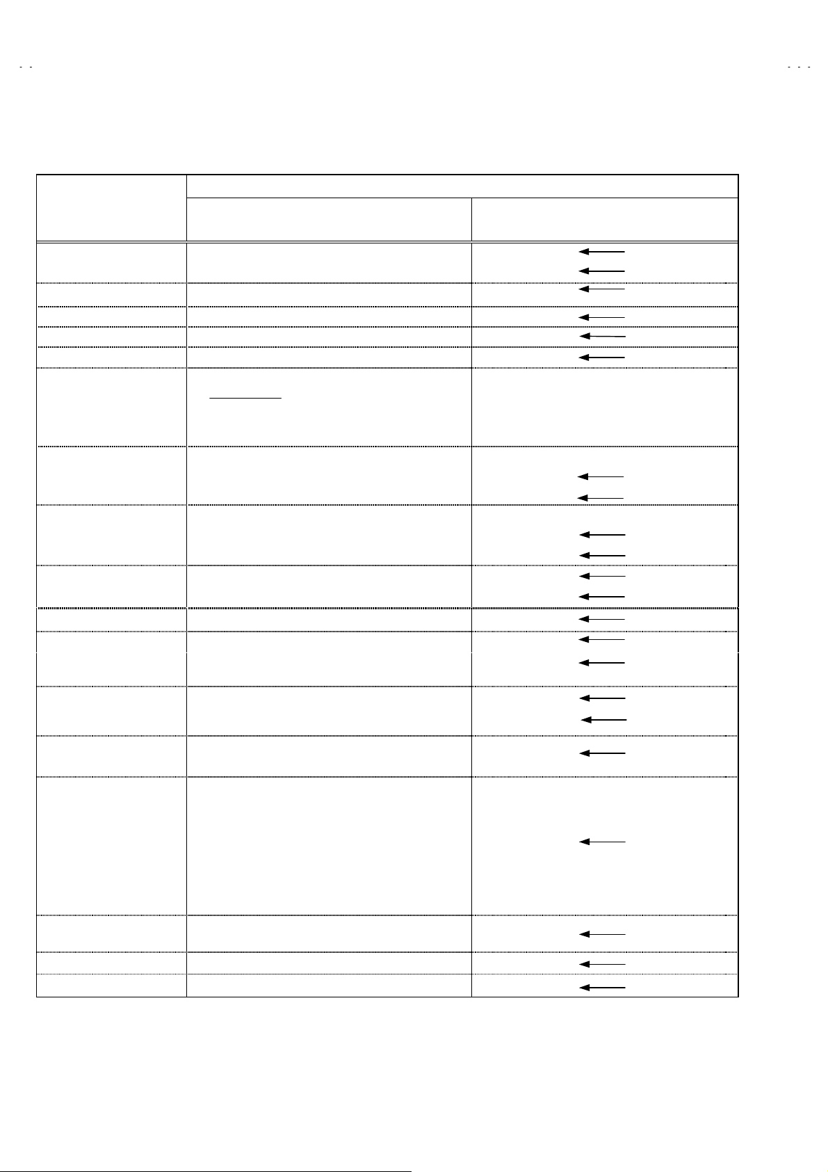
21-pin Euro connector (SCART socket) : EXT-1 / EXT-2 / EXT-3
(P-P= Peak to Peak, S-W = Sy nc ti p to whit e peak , B-W = Blanking to whit e peak )
V32S2EKGR
V32S2EKBL
V32S2EIGR
Pin
No.
Signal Designation Matching Value EXT-1 EXT-2 EXT-3
1 AUDIO R output 500mVrms(Nominal),
Low impedance
2 AUDIO R input 500mVrms(Nominal),
High impedance
3 AUDIO L output 500mVrms(Nominal),
Low impedance
4 AUDIO GND
5 GND (B)
6 AUDIO L input 500mVrms(Nominal),
High impedance
7B input
8 FUNCTON SW
(SLOW SW)
9 GND (G)
10 SCL3 NC
11 G input
12 SDA3 NC
13 GND (R)
14 GND (YS)
15 R / C input
16 Ys input
17 GND(VIDEO output)
18 GND(VIDEO input)
19 VIDEO out pu t
20 VIDEO / Y input
21 COMMON GND
700mV
Low : 0-3V, High : 8-12V, High
impedance
700mV
R : 700mV
C : 300mV
Low : 0 - 0.4, High : 1 - 3V, 75
1V
1V
, 75
Ω○
B-W
, 75
Ω○
B-W
, 75
Ω
B-W
, 75
Ω
P-P
(Neg ati ve g oin g s ync ) , 75
P-P
(Neg ati ve g oin g s ync ) , 75
P-P
Ω○
Ω○
Ω○ ○ ○
(TV OUT)
(TV OUT)
(only R)
(TV)
○
○○○
○
○○○
○○○
○○○
○○○
○○○
○○○
○
○
○○○
○○○
○○○
○
(LINE OUT)
○
(LINE OUT)
NC NC
○
NC NC
○
NC NC
○
(only C)
NC NC
○
(LINE OUT)
NC
NC
NC
NC
○
(only C)
NC
Pin assignment
[
]
No.51804
3
Page 4

A
V32S2EKGR
A
A
V32S2EKBL
V32S2EIGR
SAFETY PRECAUTIONS
1. The design of this pr oduc t contains speci al hardw are and man y
circuits and components specially for safety purposes. For
continued protection, no changes should be made to the original
design unless authorized in writing by the manufacturer.
Replacement parts must be identical to those used in the original
circuits. Service should be performed by qualified personnel
only.
2. Alter at i ons of the d esi g n or c irc uitry of the pr oduct s h oul d n ot b e
made. Any design alterations or additions will void the
manuf act urer's warr anty and will fur t her reliev e the manuf actur er
of responsi bility f or person al injury or pr operty dam age res ulting
therefrom.
3. Many electrical and mechanical parts in the product have special
safety-related characteristics. These characteristics are often not
evident from visu al ins pec tion n or can th e protect i on aff orded by
them nec essar y be obtain ed by usi ng repl acemen t comp onent s
rated for hi gher volt age, wattag e, etc. R eplacem ent parts whic h
WARNING
have these special safety characteristics are identified in the
Parts List of S er vice Man ual. El ec t rical comp onents h avi n g s u ch
features ar e i d entifi ed b y s h ad ing on th e s c h em at ic s an d b y (!)
on the P arts Lis t in th e Ser vic e Man ual. Th e us e of a subst itu te
replacement which does not have the same safety
charact erist ics as the rec omm ended r eplacem ent par t shown in
the Par ts L i s t of S ervice Man u al m ay cause shoc k, fire, or ot her
hazards.
4. The leads in the products are routed and dressed with ties,
clamps, tubing’s , bar riers and the like to b e separ ated fr om li ve
parts, high temperature parts, moving parts and / or sharp edges
for the prevention of electric shock and fire hazard. When
servic e is r eq uired, t he origin al l ead routi ng and dr ess s h ou ld be
observed, and it should be confirmed that they have been
return ed t o nor m al , after re-as sembli ng.
1. The equipment has been designed and manufactured to meet international safety standards.
2. It is the legal responsibility of the repairer to ensure that these safety standards are maintained.
3. Repairs must be made in accordance with the re levant safety standards.
4. It is essential that safety critical components are replaced by approved parts.
5. If mains voltage selector is provided, check setting for local voltage.
4
No.51804
Page 5
A
A
A
FEATURES
V32S2EKGR
V32S2EKBL
V32S2EIGR
By preference, users c an select t h e p ic ture si z e from RE G ULA R ,
"
PANORAMIC, FUL L, 14 :9 ZOOM , 16: 9 ZOOM, 16:9 ZOOM SUB
TITLE modes. When the TV unit received WSS picture signal, the
picture can be changed to 16:9 ZOOM mode automatically.
The TELETEXT SYSTEM has a built-in FASTEXT and WST
"
system.
B ecause this TV uni t corresp onds t o multipl ex broadc ast, us ers
"
can enjo y music pr ograms an d spor ting ev ents wit h live real ism.
In additi on, BILINGUAL programs c an be heard in their original
language.
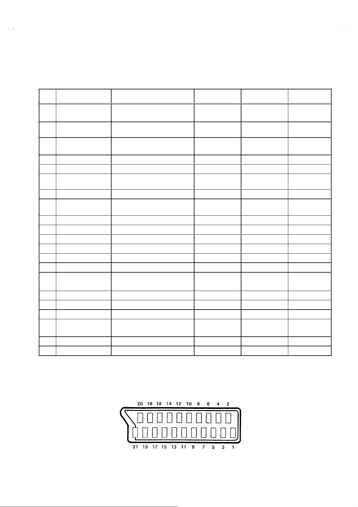
TV EXT-1 EXT-3
EXT-2
Built-in ECO (ECONOMY, ECOLOGY) MODE.
"
In accordance with the brightness in a room, the brightness
and/or contrast of the picture can be adjusted automatically to
make th e opti mu m pictur e wh ic h is eas y on th e ey e.
Users can make VCR dubbing of picture and sound by controlling
"
the AV select or to sel ect an opti onal sour ce at the E XT-2 output
shown in figure.
EXT-4
MAIN DIFFERENCE PARTS LIST
Model Name
!!!!
Part Name
MAIN PWB SJK-1914A-U2
AV SEL. PWB SJK0S914A-U2
FRONT FRAME LC10851-002B-U LC10851-003A-U LC10851-002B-U
!
RATING LABEL LC20091-034A-U LC20091-035A-U LC20091-036A-U
!
INST BOOK LCT0895-001A-U
REG. SHEET AEM3148-001-E
AV32S2EKGR AV32S2EKBL AV32S2EIGR
←
←
←
←×
SJK-1714A-U2
SJK0S714A-U2
LCT0896-001A-U
No.51804
5
Page 6
A
V32S2EKGR
A
A
A
V32S2EKBL
V32S2EIGR
SPECIFIC SERVICE INSTRUCTIONS
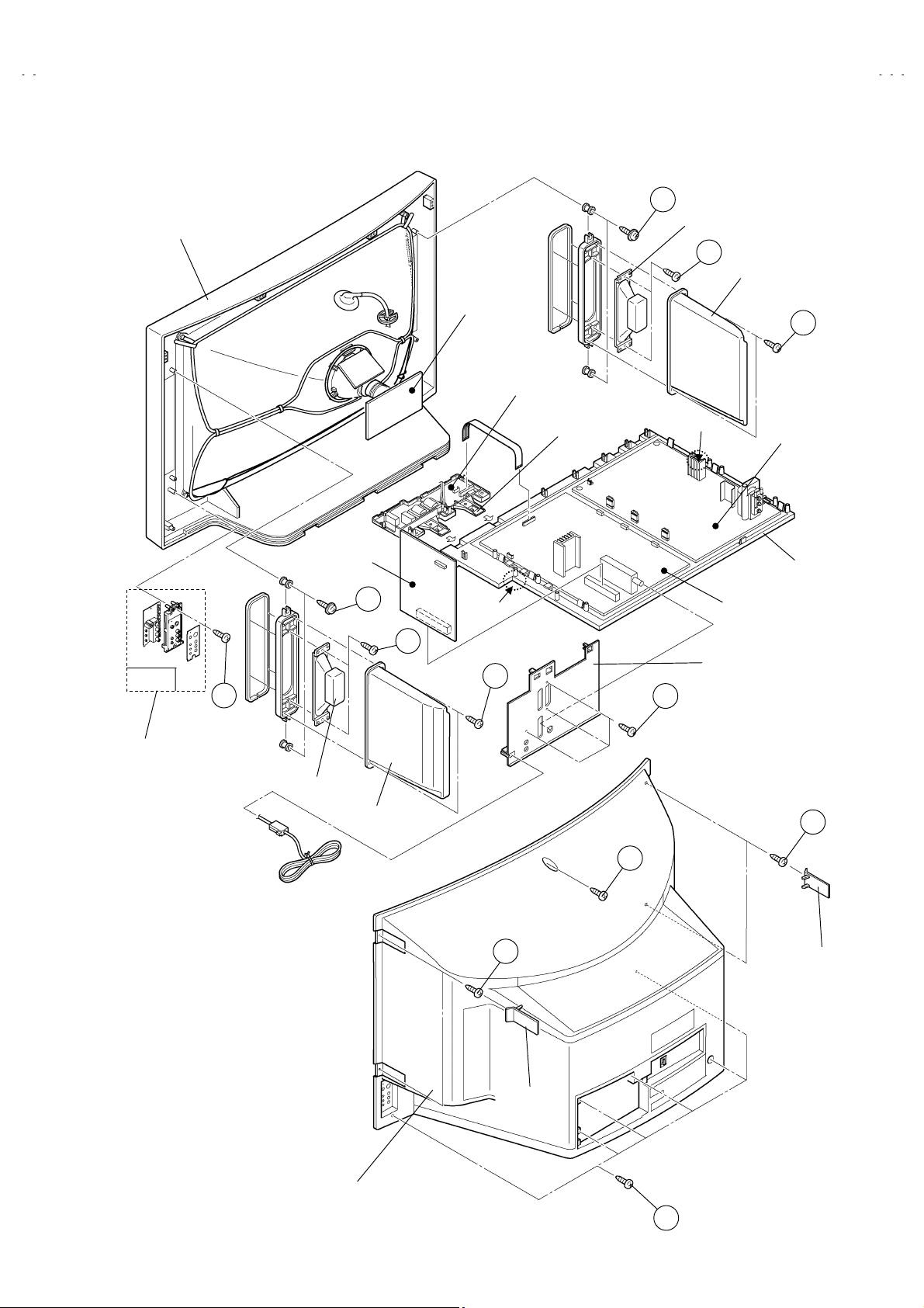
DISASSEMBLY PROCEDURE
REMOVING THE REAR COVER
1. Unplug the power cord.
2. Remove the 4 screw caps from rear cover as shown in Fig.1.
3. Then remove 11 screws marked ”A” as shown in the Fig. 1.
4. Withdraw the rear cover toward you.
REMOVING THE SIDE C ON TRO L JACK ASSEMBLY
After removing the re ar cover.
"
1. Remo ve th e sc rew marked B as shown in the Fig.1.
2. While sli ghtly r aise th e s id e control jac k assembl y, r em o ve the 2
claws under the side control jack assembly.
3. Disconnec t t he c onn ector “SR”, “SL”, “S”, “F” and “K” as shown
in Fig 2.
REMOVING THE SIDE CONTROL PWB
After removing the rear cover and side control jack assembly.
"
1. Remove the 3 c laws “C” f rom b ack s i d e of t h e s i d e co n tro l j ac k
assembly as shown in Fig.2.
2. Pull out the SIDE CONTROL PWB.
REMOVING THE CHASSIS
After removing the re ar cover.
"
1. Slightl y rais e the b ot h sid es of the c hass is b y h and and r em ove
the two c laws und er th e both s id es of the c has sis from the f r ont
cabinet.
2. Withdraw the chassis backward.
(If necessary, take off the wire clamp, connectors etc.)
REMOVING THE SPEAKER BOX
After removing the re ar cover.
"
1. Remove the 2 screws marked ”D” as shown in Fig. 1.
: When removi ng the scr ews marked D of th e speaker b ox
NOTE
assembly, remove the lower side screw first, and then
remove the upper one.
2. Remove the 2 screws “E” attaching the speaker box.
3. Remove the 2 screws “F” attaching the speaker.
4. Follow the same steps when removing the other hand speaker.
REMOVING THE AV TERMINAL BOARD
After removing the re ar cover.
"
1. Remove the 3 screws marked ”G” as shown in the Fig. 1.
2. Remo ve th e c laws m arked “H” under t he CH ASS IS as sh own in
Fig. 3.
3. While raising the claw marked “I”, remove the top of the AV
TERMINAL BOARD slightly in the direction of arrow ”J” as
shown in Fig. 3.
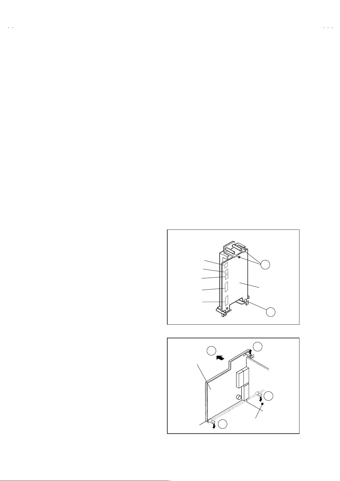
CHECKING THE PW BOARD
To check the back side of the PW Board.
1) Pull out the chassis. (Refer to REMOVING THE CHASSIS).
2) Erect t he ch assis vertic ally s o that you c an easi ly ch eck th e
back side of the PW Board.
[CAUTION]
When erecting the chassis, be careful so that there will be no
"
co n tac ti ng wit h oth e r PW B o ard .
Before turning on power, make sure that the wire connector is
"
properly connected.
When conducting a check with power supplied, be sure to confirm
"
that the CRT EARTH WIRE (BRAID ED ASS’Y) is conn ected to
the CRT SOCKET PW board.
WIRE CLAMPING AND CABLE TYING
1. Be sure to clamp the wire.
2. Never remove the cable tie used for tying the wires together.
Should it be inad ver tent l y remov ed, b e sur e to ti e th e wir es with
a new cable tie.
Connector
SR
SL
S
F
K
Fig. 2
J
V TERMINAL
BOARD
C
SIDE CONTROL
PWB
C
I
H
H
AV SEL. PWB
Fig. 3
6
No.51804
Page 7
A
A
A
FRONT CABINET
CRT
SOCKET
PWB
FRONT
CONTROL
PWB
D
SPEAKER
F
V32S2EKGR
V32S2EKBL
V32S2EIGR
SPEAKER
BOX
E
Fig. 2
SIDE
CONTROL
JACK
ASSEMBLY
AV SEL. PWB
D
CONTROL
BASE
CLAW
F
CLAW
AV TERMINAL
BOARD
POWER &
DEF. P WB
MAIN PWB
CHASSIS
E
B
SPEAKER
SPEAKER
BOX
G
A
A
A
SCREW
CAP
REAR COVER
Fig. 1
A
No.51804
SCREW
CAP
7
Page 8
A
V32S2EKGR
A
A
A
A
A
A
A
V32S2EKBL
V32S2EIGR
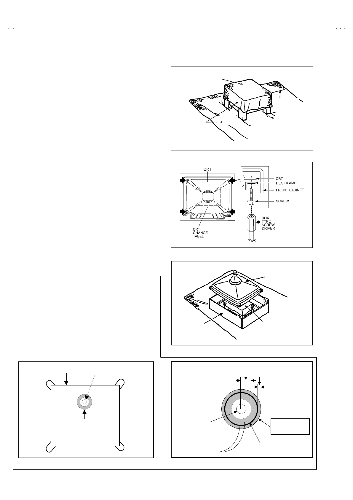
REMOVING THE CRT
Replacement of the CRT should be performed by 2 or more
!
persons.
After removing the cover, chassis etc.,
"
1. Putting the CRT change table on soft cloth, the CRT change table
should also be covered with such soft cloth (shown in Fig.4).
2. While keeping the surface of CRT down, mount the TV set on the
CRT change table balanced will as shown in Fig.5.
3. Remove 4 sc rews mark ed by arr ows w ith a b ox type screw dri ver
as shown in Fig.5.
Sinc e t h e cabin et will drop wh en s c rews have been rem o ved , be
"
sure to support the cabinet with hands.
4. After 4 sc rews have been removed, put th e cabinet sl owly on
cloth (At this time, be carefully so as not to damage the front
surface of the cabinet) shown in Fig.6.
The CRT should be assembled according to the opposite
"
sequence of its dis m oun ti ng steps.
T he CRT ch ang e table shoul d pr eferabl y be smal l er th at th e CRT
!
surfac e, and its heig ht b e ab out 35cm.
CRT CHANGE TABLE
PPROX.
35cm
CLOTH
Fig. 4
COAT ING OF SILICON GREASE FO R ELECTRICAL
INSULATION ON THE CRT ANODE CAP SECTION.
Subs equent t o replac ement of the CRT and HV tr ansformer or
"
repair of the anode c ap, etc. by dismou nting them, be sure to
coat silicon greas e f or el ec trical insulati on as sh own in F i g. 7.
Wipe around the anode button with clean and dry cloth. (Fig.7)
Coat sil icon gr eas e on t he s ection arou nd the anod e but ton. A t
this ti me, t ak e c are s o th at an y si lic on gr eas es d os e not s tic k to
the anode button. (Fig.8)
Silicon grease product No. KS - 650N
★★★★
CRT
node button
Silicon gr ease
coating
CABINET
pprox.
20mm (Do not
coat grease on
this section
node button
(No sticking of
silicon grease)
Fig. 5
CRT
CRT
CHANGE TABLE
Fig. 6
Silicon gr ease
should b e c oat ed
by 5mm or mor e
from the outside
diamet er of
anode cap.
Coating positi on
of silicon grease
node cap
Fig. 7 Fig. 8
8
No. 51804
Page 9
A
A
A
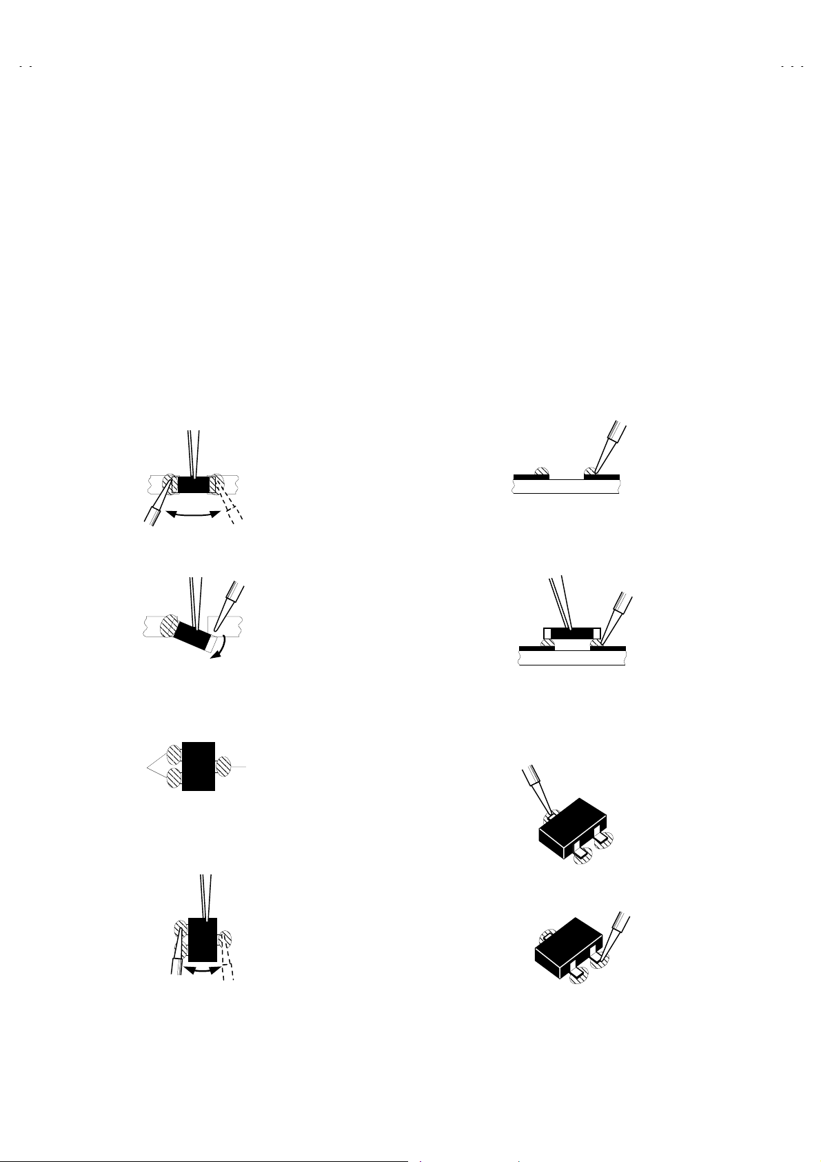
REPLACEMENT OF CHIP COMPONENT
CAUTIONS
!
1. Avoid heating for more than 3 seconds.
2. Do not rub the electrodes and the resist parts of the pattern.
3. When removing a chip part, melt the solder adequately.
4. Do not reuse a chip p art af t er r em ovi ng it.
SOLDERING IRON
!
1. Use a high ins ul ati on solderin g iron with a thi n p oint ed end of it.
2. A 30w soldering iron is recommended for easily removing parts.
REPLACEMEN T STEPS
!
How to remove Chip parts
1.
Resistors, capacitors, etc
####
(1) As shown in the figure, push the part with tweezers and
alternately m elt th e s older at each en d.
(2) S hif t wi th tweezers and remo ve th e ch ip part.
Transistors, diodes, variable resistors, etc
####
(1) Apply extra solder to each lead.
V32S2EKGR
V32S2EKBL
V32S2EIGR
2. Ho w to install Chip parts
Resistors, capacitors, etc
####
(1) Apply solder to the pattern as indicated in the figure.
(2) Grasp th e chip part with tw eezers and pl ace it on th e sold er.
Then heat an d m elt t h e s old er at b oth en ds of th e chip part .
Transistors, diodes, variable resistors, etc
####
(1) Apply solder to the pattern as indicated in the figure.
(2) Grasp the chip part with tweezers and place it on the solder.
(3) First solder lead
as indicated in the figure.
A
SOLDER
(2) As shown in the figure, push the part with tweezers and
alternat el y melt t he s old er at each lead . Shif t and r emov e th e
chip part.
Note : After removing the part, remove remaining solder from the
pattern.
SOLDER
No.51804
A
C
(4) Then solder leads
A
C
and C.
B
B
B
9
Page 10
A
V32S2EKGR
A
A
V32S2EKBL
V32S2EIGR
REPLACEMENT OF MEMORY ICs
1. Memory ICs
This TV use mem ory ICs . In the mem or y ICs, there ar e memor iz ed dat a
for cor rectl y op er ating th e vi deo an d def l ection cir cu its. W h en r epl acing
memory ICs, be sure to use ICs written with the initial values of data.
2. Procedure for replacing memory ICs
PROCEDURE
(1)
Power off
Switch th e p ow er off and unpl ug the p ow er c ord from the w all ou tl et.
(2)
Replace ICs
.
Be sure to use memory ICs written with the initial data values.
(3)
Power on
Plug the power cord into the wall outlet and switch the power on.
(4)
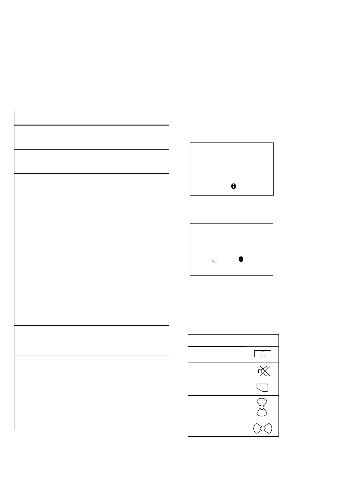
Check and set SYSTEM CONSTANT SET:
It must not adjust with ou t sign al.
****
1) Press the INFORMATION key and the MUTING key of the
REMOTE CONTROL UNIT simultaneously.
2) T he SERVICE MEN U scr een of F ig . 1 wil l b e dis pl ay ed.
3) While the SERVICE MENU is displayed, press the
INFORM ATION key and MUT ING key s imultan eousl y, and th e
SYSTEM CONSTANT SET screen of Fig. 2 wi ll b e dis pl ay ed .
4) Ch eck t he s etti ng valu es of th e SYS TE M CON STA NT S ET of
Table 1. If the valu e is dif f erent , s elect the s et ting item wi th th e
FUNCTION UP/DOWN key, and set th e correct value with the
FUNCTION -/+ key.
5) Press the MENU key to memorize the setting value.
6) Press the INFORM ATION key twice, and return to the normal
screen.
SERVICE MENU
1. IF 2. V/C
3. AUDIO 4. DEF
5. VSM PRESET 6. STATUS
7. SHIPPING (OF F)
1-7 : SELECT : EXIT
Fig.1
SYSTEM CONSTANT SET
MODEL=JK_EURO (V
COUNTRY :
INCH :
MODEL :
OK
- + : STORE : EXIT
JVC JK EURO V00
******** - *****
Fig.2
*.****
**
**
**
)
(5)
Setting o f re ce iv e channel s
Set the receive channel.
NAME OF REMOTE CONTROL KEY
Names of key
key
For setting, refer to the OPERATING INSTRUCTIONS.
(6)
User setti n gs
Check th e us er s ett in g values of T abl e 2, and if setti ng v al ue is
INFORMATION
MUTING
iiii
different, set the correct value.
For setting, refer to the OPERATING INSTRUCTIONS.
OK
▼
▼
(7)
Setting of SERVICE MENU
Verif y the s etting items of th e
wh ere neces sary .
SERVICE MENU
of Table 3, and reset
MENU
FUNCTION UP/DOWN
For setting, refer to the SERVICE ADJUSTMENTS.
▼
FUNCTION -/+
10
No. 51804
▼
Page 11

A
A
A
SETTIN G VALUES OF SYSTEM CONSTANT SET (TABLE 1)
Setting value
Setting item Setting content
COUNTRY EK IR
ENEKEP
EE IR
AV32S2EKGR
AV32S2EKBL
V32S2EKGR
V32S2EKBL
V32S2EIGR
AV32S2EIGR
INCH 32 32
MODEL WFT
28
32
WFRWFT
USER SETTING VALUES (TABLE 2)
PICTURE SETTING EXT SETTING
TINT
CONTRAS
BRIGHT
SHARP
COLOUR
ECO MODE
VNR
COLOUR SYSTEM
4:3 AUTO ASPECT
BASS
TREBLE
BALANCE
BBE
HYPER SOUND
TV SPEAKER
COOL
REFER to VSM PRESET
OFF
PICTURE FEATURES FEATURES
AUTO
TV : According to preset CH
EXT : AUTO
PANORAMIC
SOUND SETTING INSTALL
CENTER
ON
OFF
L/R
EX T SETTING
DUBBING
SLEEP TIMER
BLUE BACK
CHILD LOCK
DECODER (EXT-2)
LANGUAGE
EDIT
ID : BLACK
S-IN : BLACK
EXT-1→EXT-2
OFF
ON
ID : No.
OFF
ENGLISH
PRESET CH only
The others : BLANK
****
ALL CH : OFF
SERVICE MENU SETTING ITEMS (TABLE 3)
Setting item Setting value Setting item Setting value
1. IF VCO 4. DEF. 1. V-SHIFT
2. V / C 1. CUT OFF(R/G/B)
3.AUDIO
(Do not adjust)
2. DRIVE(R/B)
3. BRIGHT
4. CONT.
5. COLOUR
6. HUE
7. BLACK OFFSET (Only SECAM)
8. SHARP(Do not adjust)
9. PU RITY(Do n ot adjust)
1. CONC LIMIT
2. A2 ID THR
3. ALC
4. BASS
5. TREBLE
5. VSM PRESET
COOL
NORMAL
WARM
6. STATUS
(Do not adjust)
7. SHIPPING(OFF)
(Do not adjust)
2. V-SIZE
3. SUBTITLE
4. H-CENT
5. H-SIZE
6. EW-PIN
7. TRAPEZ
8. EW. COR. L
9. EW. COR. H
10. V. S-COR
11. V- LIN
12. H-BLK-R
13. H-BLK-L
14. V-EHT
15. H-EHT
16. EHT-G AIN
1. BRIGHT
2. CONT.
3. COLOUR
4. SHARP
5. HUE
6. R DRIVE
7. B DRIVE
VPS
PDC
OFF(ON / OFF)
(Do not adjust)
No. 51804
11
Page 12

A
V32S2EKGR
A
A
V32S2EKBL
V32S2EIGR
SERVICE ADJUSTMENTS
BEFORE STARTING SERVICE ADJUSTMENT
1.
There are 2 ways of adjusting this TV: One is with the
REMOTE CONTRO L UNIT and t he oth er is t he conv ention al
method using adjustment parts a nd components.
2.
The setting (adjustment) using the REMOTE CONTROL
UNIT is ma de on t he b asis of th e initi al se tting v alue s. The
setting values which adjust the screen to the optimum
condition can be different from the initial setting values.
3. Make sure that connection is correctly made to AC power
source.
4. Turn on the power of the TV and measuring instrument for
warming up for at least 30 minutes before starting adjustment.
5. If the receive or input signal is not specified, use the most
appropriate signal for adjustment.
6. N ever touc h parts ( suc h as vari able r esist ors, tr ansf ormers and
condens ers) not show n in the adj ustment i tems of this s ervice
adjustment.
7. Preparation for adjustment (presetting):
Unless oth erwise sp ecified in t he adjust ment items , preset t he
following functions with the REMOTE CONTROL UNIT:
Setting position
"
PICTURE MODE (VSM) NORMAL
SLEEP TIMER OFF
BALANCE CENTER
ECO OFF
ASPECT PANORAMIC
MEASURING INSTRUMENT AND FIXTURES
1. DC vol t meter (or digital volt meter)
2. Oscilloscope
3. Signal generator ( Pattern generator) [PAL / NTSC]
4. Remote control unit
ADJUSTMENT ITEMS
Checking items.
●
Adjustment of FOCUS.
●
IF circuit adjustment.
●
VSM preset s etti ng.
●
VIDEO / CHROMA circuit adjustment.
●
DEFLECTION circuit adjustment.
●
H. BLANKING ADJUSTMENT.
●
AUDIO circuit adjustment. (Do not adjust)
●
12
No. 51804
Page 13

A
A
A
ADJUSTMENT LOCATIONS
SIDE CONTROL PWB
TOP
V32S2EKGR
V32S2EKBL
V32S2EIGR
SR
SL
FRONT
FRONT
FRONT CONTROL PWB
F901
PW
POWER SW
MAI N PWB POWER&DEF PWB
CN001
AV SEL PWB
CN006
S
UP
CN102
W
DOWN
MENU
F
K
FRONT
IC701
IC702
L
MEMORY
W DEG
TOP
TUNER
CRT SOCKET PWB
TP-47R
TP-47G
CN008
TP-E
IC301
CN008
(SOLDER SIDE)
TP-47B
E1
CN009
CN009
HV
HVT
FOCUS 1 VR
FOCUS 2 VR
SCREEN
X
1
5
1pin:B1(TP-91)
2pin:NC
3pin:NC
4pin:NC
5pin:GND
No. 51804
13
Page 14

A
V32S2EKGR
A
A
V32S2EKBL
V32S2EIGR
BASIC OPERATION SERVICE MENU
1. TOOL OF SERVICE MENU OPER ATIO N
Operate the SERVICE MENU with the REMOTE CONTROL UNIT.
2. SERVICE MENU ITEMS
With the S ERVIC E MENU, vari ous s ettings (adjust ments ) can be made, and the y are br oadly c lassif ied in th e f ollowing items of settings
(adjustments):
(1)
1. IF
・・・・・・・・・・・・・・・・・・・・・・・
(2)
2.V/C
・・・・・・・・・・・・・・・・・・・・・・
(3)
3.AUDIO
(4)
4.DEF
・・・・・・・・・・・・・・・・・・・・・
(5)
5.VSM PRESET
(6)
6.STATUS
(Do not adjust)
(7)
7.SHIPPING(OFF)
(Do not adjust)
・・・・・・・・・・・・・・・・・・・
・・・・・・・・・・・・・
・・・・・・・・・・・・・・・・・
(VPS : Video Program System,/PDC : Program Delivery Code)
・・・・・・・・・・・
This mode adjusts the setting values of the IF circuit.
This mode adjusts the setting values of the VIDEO / CHROMA circuit.
This mode adjusts the s etting val u es of the multi pl ic it y SOUND circui t.
This mode adjusts the setting values of the DEFLECTION circuit for each aspect mode given below.
REGULAR (50/60Hz)
PANORAMIC (50/60Hz)
14:9 ZOOM (50/60Hz)
16:9 ZOOM (50/60Hz)
16:9 ZOOM SUB TITLE (50/60Hz)
FULL (50/60Hz)
This mod e adj us ts the initial s ett in g values of COO L,N OMAL an d W A RM.
(VSM : Video Status Memory)
This mode shows the monitor of the VPS and PDC.
Don’t select under the adjustment.
3. BASIC OPERATION OF SERVICE MENU
(1)
How to enter SERVICE MENU
Press the INFORMATION key and the MUTING key of the
REMOTE CONTROL UNIT simultaneously, and the
SERVICE ME NU sc r een of Fi g. 1 wi ll b e dis pl ay ed.
(2)
Selection of SUB MENU SCREEN
Press one of keys 1~7 of the REMOTE CONTROL UNIT
and select the SUB MENU SCR EEN (See Fi g. 3), f orm the
SERVICE MENU.
SERVICE MENU → SUB MENU
1. IF
2. V / C
3. AUDIO
4. DEF.
5. VSM PRESET
(Do not adjust)
6. STATUS
7. SHIPPING(OFF)
SERVICE MENU
SERVICE MENU
1. IF 2. V/C
3. AUDIO 4. DEF
5. VSM PRESET 6. STATUS
7. SHIPPING(OFF)
1-7 : SELECT : EXIT
Fig.1
NEME OF REMOTE CONTOROL KEY
Names of key
INFORMATION
MUTING
MENU
FUNCTION UP/DOWN
FUNCTION -/+
Fig.2
key
iiii
OK
▼
▼
▼
▼
14
No. 51804
Page 15

A
A
A
SERVICE MENU
SERVICE MENU
1. IF 2. V/C
3. AUDIO 4. DEF
5. VSM PRESET 6. STATUS
7. SHIPPING (OFF)
1-7 : SELECT : EXIT
SUB MENU 7. SHIPPING(OFF)
(Do not adjust)
7. SHIPPING (OFF)
7. SHIPPING (ON)
V32S2EKGR
V32S2EKBL
V32S2EIGR
COOL
NORMAL
WARM
1. BRIGHT
2. CONT.
3. COLOUR
4. SHARP
5. HUE
6. R DRIVE
7. B DRIVE
SUB MENU 5. VSM PRESET
VSM PRESET NORMAL
1.BRIGHT
- + : STORE : EXIT
OK
SUB MENU 6. STATUS
(Do not adjust)
VPS = 0000H(- - -)
PDC 8 / 30 / 1 = 0404H
***
VPS
: EXIT
SUB MENU 1.IF (VCO)
VCO (CW)
1. CUT OFF (R)
- +
**
**....**
**
****
****
TOO HIGH
ABOVE REFERENCE
JUST REFERENCE
BELOW REFERENCE
TOO LOW
SUB MENU 2. V/C
V/C
PAL
(G)
(B)
OK
: STORE : EXIT
MHz
****
****
****
: EXIT
1. CUT OFF
2. DRIVE
3. BRIGHT
4. CONT.
5. COLOUR
6. HUE
7. BLACK OFFSET
(SECA only)
8. SHARP (Do not adjust)
9. PURITY (Do not adjust)
SUB MENU 3. AUDIO (Do not adjust)
AUDIO
1. CONC LIMIT 0AH
C AD BITS =
OK
- +
SUB MENU 4. DEF
DEF PANORAMIC
1. V-SHIFT
- +
OK
********
: STORE : EXIT
: STORE : EXIT
Fig. 3 SUB MENU SCREEN
No. 51804
***
(**)
1. CONC LIMIT
2. A2 ID THR
3. ALC
4. BASS
5. TREBLE
1. V-SHIFT
2. V-SIZE
3. SUBTITLE
4. H-CENT
5. H-SIZE
Hz
**
**
****
6. EW-PIN
7. TRAPEZ
8. EW.COR.L
9. EW.COR.H
10. V.S-COR
11. V-LIN
12. H-BLK-R
13. H-BLK-L
14. V-EHT(Do not adjust)
15. H-EHT(Do not adjust)
16. EHT-GAIN(Do not adjust)
15
Page 16

A
V32S2EKGR
A
A
V32S2EKBL
V32S2EIGR
(3)
Method of Setting
1) M eth od of Setting
[VCO]
1 Key
①
The VCO (CW) screen w il l be dis play ed in yel l ow when the AFC vol tage is at a c ertain level and in blu e w h en it is at other lev els.
②
INFORMATION Key
③
1.IF
・・・・・・・・・・・・・・・・・・・・・・・・・
・・・・・・・・・・・・
Select 1.IF.
Return to the SERVICE MENU screen.
2) Method of setting
5 Key
①2~
FUNCTION UP/DOWN Key
②
FUNCTION -/+
③
MENU Key
④
INFORMATION Key
⑤
3) Method of setting
6.STATUS
7.AUTO PROGRAM
(4)
Release of SERVICE MENU
1) After completing the setting, return to the SERVICE MENU, then again press the INFORMATION key.
(Do not adjust)
(Do not adjust in this mode.)
2.V/C, 3.AUDIO, 4.DEF
・・・・・・・・・・・・・・・・・・・・・・
・・・・・
・・・・・・・・・・・・・・・・・
・・・・・・・・・・・・・・・・・・・・
・・・・・・・・・・・・
6.STATUS
・・・・・・・・・・・・・・・
and
・・・・・・・・・
and
5.VSM PRESET.
Select on e from
Select setting items.
Set (adjust) the setting values of the setting items.
(Use the number keys of the REMOTE CONTROL UNIT for setting of WHITE BALANCE.
For the setting, refer to each item concerned.)
Memorize the setti ng value.
(Before storing the setting values in memory, do not press the CH, TV, POWER ON / OFF key if you do, the values will not be stored in memory.)
Return to the
7.SHIPPING
This mode displayed monitor of VPS syst ems.
When the MAIN POW ER is turned on with th e state of SHIPPING ON, you g et a mod e that
initiali z es e very exis ti ng set val ue incl ud in g langu age selection. B ecause this mode is set at the
factory upon c omp l etion of the adj us t m en t, you need not to use it for service.
2. V/C, 3. AUDIO, 4. DEF
SERVICE MENU
.
screen.
and
5. VSM PRESET
.
16
No. 51804
Page 17

A
A
A
ADJUSTMENTS
CHECKING ITEM
V32S2EKGR
V32S2EKBL
V32S2EIGR
Item
Check of B 1
Power Supply
Check of Hi gh
Voltage
Measuring
instrument
Signal
Generator
DC voltmeter
Remote
Control unit
Signal
Generator
DC volunteer
Remote
Control unit
Test point Adjustment part Descrip tion
TP-91(B1)
TP-E(
)
""""
[X connector
on POWER
DEF P WB]
CRT anode
Chassis GND
1. Rec eive an y broadcast.
2. Push the “ZOOM” key and select the FULL mode.
3. Select 2. V/C from the SERVICE MENU.
4. Select 1. CUT OFF with Function UP / DOWN key.
5. Show hor i z ont al on e line wit h th e 1 key.
6. Turn th e SCR EE N VR, the w h ole bl ack scr een dis play.
7. Connect a DC voltmeter to TP-91(B1) and TP-E(").
8. Make sure that the voltage is DC139.9 ±2.0V.
9. Readj us t the SCR EE N VR t o ap p ear t he hori z ontal li n e f aintly,
and cancel the horizontal line to press the 2 key.
1. Rec eive an y broadcast.
2. Push the “ZOOM” key and select the FULL mode.
3. Select 2. V/C from the SERVICE MENU.
4. Select 1. CUT OFF with Function UP / DOWN key.
5. Show hor i z ont al on e line wit h th e 1 key.
6. Turn th e SCR EE N VR, the w h ole bl ack scr een dis play.
7. Connect a DC voltmeter to CRT ANODE and chassis GND.
8. Make sure that the voltage is DC 31.0kV .
9. Readj us t the SCR EE N VR t o ap p ear t he hori z ontal li n e f aintly,
and conn ec t th e hor i z ontal line t o press 2 k ey.
+1kV
-1.5kV
ADJU STMENT OF F OCUS
Item
Adjustment of
FOCUS
Measuring
instrument
Signal
generator
Test point Adjustment part Descrip tion
FOCUS VR
[In FBT]
FOCUS 1 VR
FOCUS 2 VR
SCREEN VR
1. Receive a cross-hatch signal.
2. By tur ning t he FOCU S 2 VR, adjust the t o make the vertic al
lines as fin e an d sh arp as p oss ib le.
3. By tur ni ng th e FO CUS 2 VR, adjus t the pic t ure so t h at the 5t h
vertic al line f rom left side of th e c ross-h atch pic tur e bec omes
thinnest.
4. By turning the FOCUS 1 VR, adjust the 3rd horizontal line from
the upper s id e may b ecome unif orm at th e line c ent er and its
periphery.
5. Carry out ad jus t m ent by repeat ing the st eps 3 and 4 ab ou t .
6. Make sure t hat when th e s cr een is d ark ened, the l ines r emai n
in good foc us .
FOCUS 2
FOCUS 1
No. 51804
17
Page 18

A
V32S2EKGR
A
A
V32S2EKBL
V32S2EIGR
IF CIRCUIT ADJUSTMENT
Item
Measuring
instrument
Adjustment of
VCO
Remote
control unit
***.**
VCO(CW)
TOO HIGH
ABOVE REFERENCE
JUST REFERENCE
BELOW REFERENCE
TOO LOW
: EXIT
VSM PRESET SETTING
Item
Setting of
VSM PRESET
Measuring
instrument
Remote
control unit
Test point Adjustment pa rt Descrip tion
U nd er n or m al c ond iti ons , no adjus t m ent is r equ ired.
"
1. Rec eive an y broadcast.
2. Select 1.IF from the SERVICE MENU.
3. Check the characters colour of between the “ABOVE
REFERENCE” and “BELOW REFERENCE” displayed to
MHz
fv
YELLOW
yellow.
Test point Adjustment part Descrip tion
1. BRI G HT
2. CONT.
3. COLOUR
4. SHARP
5. HUE
6. R DRIVE
7. B DRIVE
1. Select 5.VSM PRESET from the SERVICE MENU.
2. Select COOL with the MENU key of the remote control unit.
3. Adjust the FUNCTION UP/DOWN and -/+ key to bring the set
valu es of 1.BRIGHT ~ 7. B DRIVE to the values shown in the
table.
4. Press the ME NU k ey an d memori z e the set valu e.
5. Resp ect i vel y select th e VSM PR E S E T m od e for NORMAL and
WAR M, and m ak e sim il ar ad jus t m ent as in 3 above.
6. Press the ME NU k ey an d memori z e the set valu e.
Refer to OPERATING INSTRUCTIONS for the PICTURE
!
MODE.
18
VSM preset mode
Setting item
1. BRIGHT
SETTING VALUE
2. CONT.
SETTING VALUE
3. COLOUR
SETTING VALUE
4. SHARP
SETTING VALUE
5. HUE
SETTING VALUE
6. R DRIVE
SETTING VALUE
7. B DRIVE
SETTING VALUE
No. 51804
COOL NORMAL WARM
000
+12 +10 +2
+6 0 -2
00-2
000
-20 0 +16
+23 0 -13
SETTING VALUES OF VSM PRESET
Page 19

A
A
A
VIDEO / CHROMA CIRCUIT ADJUSTMENT
The setting (adjustment) using the REMOTE CONTROL UNIT is made on the basis of the initial setting values.
The setting values which adjust the screen to the optimum condition can be different from the initial setting values.
V32S2EKGR
V32S2EKBL
V32S2EIGR
Setting Item
(Adjustment Item )
1. CUTOFF
2. DRIVE
3. BRI GHT
4. CONT.
Item
Adjustment
of WHITE
BALANCE
(Low Light)
R -100 -100
G -100 -100
B -100 -100
R
B000000
Measuring
instrument
Signal
generator
Remote
control unit
Remote Control Unit
H.LINE ON
H.LINE OFF
Initial settin g val ue
PAL NTSC
000 000
000 000
-010 -010
Test point Adjustment part Descrip tion
1.CUT OFF
(R)
***
(G)
***
(B)
***
SCREEN VR
[In FBT]
Setting item
5. COLOUR
6. HUE
7.BLACKOFFSET
(Only SECAM)
8. SHARP (Do not adjust)
9. PURITY (Do not adjust)
Set the PICTURE MODE to NORMAL.
"
1. Rec eive a bl ac k an d w hi t e signal (c olou r off ) .
2. Select 2. V/C from the SERVICE MENU.
3. Select 1.CUT OFF with the FUNCTION UP/DOWN key.
4. Push the “ZOOM” key and select the “REGULAR” mode.
5. Show on e hor i z ont al line wit h th e 1 key.
6. Gr aduall y turn the SC REEN VR f rom t he left en d to th e ri ght
7. Press 4~9 key, and bri ng out the other 2 colou rs and make
8. Turn the SCREEN VR and bring one white horizontal line
9. Press 2 key, turn off 1.CUT OFF screen.
10. Press the ME NU k ey an d m em o ri z e t h e s et value.
Colour system
_____
R-Y
B-Y
directi on to bring on e of the red, gr een or blu e c olour f aintly
visible.
one horizontal line visible in white.
faintl y vis i bl e.
_____ _____
_____ _____
Initial settin g val ue
PAL NTSC
+014 +008
+002
-020
OFF
_____
1 2
R CUTOFF
G CUTOFF
4 5
R CUTOFF
G CUTOFF
7 8
3
B CUTOFF
6
B CUTOFF
9
No. 51804
19
Page 20

A
V32S2EKGR
A
A
(R)
(R)
(B)
(B)
V32S2EKBL
V32S2EIGR
Item
Adjustment
of WHITE
BALANCE
(High Light)
Measuring
instrument
Signal
generator
Remote
control unit
Test point Adjustment pa rt Descri ption
REMOTE CONTRO L UNIT
1 2 3
4 5
7 8
6
9
2.DRIVE
DRIVE
DRIVE
DRIVE
DRIVE
(R)
(B)
***
***
▲
▲
▼
▼
The adjustment for Low Light WHITE BALANCE should be
"
finished.
Set the PICTURE MODE to NORMAL.
"
1. Rec eive a bl ac k an d w hi t e signal (c olou r off ) .
2. Select 2.V/C from the SERVICE MENU.
3. Select 2.DRIVE with the FUNCTION UP/DOWN key.
4. Chang e th e sc reen colou r t o white with 4 k ey or 7 k ey (Drive of
Red), 6 key or 9 key (Dri ve of Blue) .
5. Press the MENU key, and memorize the set values.
Adjustment
of
SUB BR I GHT
Adjustment
of
SUB CONT.
Remote
control unit
Remote
control unit
3.BRIGHT
4.CONT.
1. Rec eive an y broadcast.
2. Select 2.V/C from the SERVICE MENU.
3. Select 3.BRIGHT with the FUNCTION UP/DOWN key.
4. Set the initial setting value with the FUNCTION -/+ key.
5. If the brightness is not the best w ith the initial s etting value,
make fin e adj us tm en t unt il y ou g et t h e bes t br ig ht n ess .
6. Press the ME NU k ey an d memori z e the set valu e.
1. Rec eive an y broadcast.
2. Select 2.V/C from the SERVICE MENU.
3. Select 4.CONT with the FUNCTION UP/DOWN key.
4. Set the initial setting value with the FUNCTION - / + key.
5. If the contrast is not the best with the initial setting value, make
fine adjustment until you get the best contrast.
6. Press the ME NU k ey an d memori z e the set valu e.
20
No. 51804
Page 21

A
V32S2EKGR
A
A
V32S2EKBL
V32S2EIGR
Item
Adjustment
of SUB
COLOUR
ⅠⅠⅠⅠ
Measuring
instrument
Remote
control unit
Test point Adjustment part Description
5.COLOUR
(PAL / NTSC)
PAL COLOUR (PAL COLOUR)
NTSC COLOUR (NTSC 3.58 COLOUR)
[Method of adjustment without measuring instrument]
1. Receive PAL broadcast.
2. Select 2.V/C from the SERVICE MENU.
3. Select 5.COLOUR with the FUNCTION UP/DOWN key.
4. Set the initial setting value for PAL COLOUR with the
FUNCTION - or + key.
5. If the colour is not the best with the initial set value, make
fine adjustment until you get the best colour.
6. Press the ME NU k ey an d memori z e the set valu e.
1. Input a N TSC 3.5 8MHz CO MPOSIT E VIDEO signal f rom th e
EXT terminal.
2. Make similar fine ad justment of NT SC 3.58 COLOUR in the
same manner as for above.
(NTSC 4.43 COLOUR)
1. When NTSC 3.58 is set, NTSC 4.43 will be automatically set at
the respective values.
No. 51804
21
Page 22

A
V32S2EKGR
A
A
V32S2EKBL
V32S2EIGR
Item
Adjustment
of SUB
COLOUR
ⅡⅡⅡⅡ
Measuring
instrument
Signal
generator
Oscilloscope
Remote
control unit
Test point Adjustment part Descrip tion
TP-47B
TP-E(
""""
[CRT
SOCKET
PWB ]
5.COLOUR
)
(PAL / NTSC)
PAL COLOUR (PAL COLOUR)
[Method of adjustment using measuring instrument]
1. Receive a PAL full field colour bar signal (75% white).
2. Select 2.V/C from the SERVICE MENU.
3. Select 5.COLOUR with the FUNCTION UP/DOWN key.
4. Set the initial setting value of PAL COLOUR with the
FUNCTION - or + key.
5. Conn ect th e osc i ll oscope between TP -4 7B an d TP -E (").
6. Adjust PAL COLOUR and bring the value of
illustration to the values are shown given below. (Voltage
difference between white (W) and blue (B)).
7. Press the ME NU k ey an d m em or i z e t h e s etting valu e.
VOLTAGE (W-B) +2V
(A)
in the
W
Cy Mg B
NTSC COLOUR (NTSC 3.58 COLOUR)
1. Input a NT SC 3.58 MHz CO MPOSITE V IDEO sign al (full f ield
colour bar with 75% white) from the EXT terminal.
2. Set the initial setting value of NTSC 3.58 COLO UR with the
FUNCTION -/+ key.
3. Adjust NT SC 3 .58 C OLO UR and brin g t he val ue of
illustr ation to
4. Press the ME NU k ey an d m em or i z e t h e s etting valu e.
(-)
(A)
0
(+)
(NTSC 4.43 COLOUR)
1. When NTSC 3.58 is set, NTSC 4.43 will be automatically set at
the respective values.
0V (
W-B)
of t he
(A)
.
22
No. 51804
Page 23

A
V32S2EKGR
A
A
V32S2EKBL
V32S2EIGR
Item
Adjustment
of
SUB HUE
ⅠⅠⅠⅠ
Measuring
instrument
Remote
control unit
Test point Adjustment part Description
6. HUE [Method of adjustment without measuring instrument]
NTSC 3.58 HUE [NTSC 3.58 HUE]
1. Input a NT SC 3.58 MHz CO MPOSITE V IDEO sign al (full f ield
colour bar with 75% white) from the EXT terminal.
2. Select 2.V/C from the SERVICE MENU.
3. Select 6. HUE with the FUNCTION UP/DOWN key.
4. Set the initial setting value of NTSC 3.58 HUE with the
FUNCTION -/+ key.
5. If you cannot get the best hue with the initial setting value,
make fin e adj us tm en t unt il y ou g et t h e bes t hu e.
6. Press the ME NU k ey an d memori z e the set valu e.
NTSC 4.43 HUE [NTSC 4.43 HUE]
1. When NTSC 3.58 is set, NTSC 4.43 will be automatically set at
the respective values.
Adjustment
of
SUB HUE
ⅡⅡⅡⅡ
Signal
generator
Oscilloscope
Remote
control unit
W
Cy Mg B
TP-47B
TP-E(
""""
[CRT
SOCKET
PWB]
6. HUE [Method of adjustment using measuring instrument]
)
NTSC 3.58 HUE [NTSC 3.58 HUE]
1. Input a NT SC 3.58 MHz CO MPOSITE V IDEO sign al (full f ield
colour bar with 75% white) from the EXT terminal.
2. Select 2.V/C from the SERVICE MENU.
3. Select 6. HUE with the FUNCTION UP/DOWN key.
4. Set the initial setting value of NTSC 3.58 HUE with the
FUNCTION - or + key.
5. Conn ect th e osc i ll oscope between TP -4 7B an d TP -E (").
6. Adjust NTSC 3.58 HUE to bring the value of (B) in the
illustr ation t o -2V (
and mag ent a (Mg) ) .
7. Press the ME NU k ey an d m emoriz e the settin g val ue
(-)
(B)
0
(+)
NTSC 4.43 HUE [NTSC 4.43 HUE]
1. When NTSC 3.58 is set, NT SC 4 .4 3 wi ll b e aut om at ically s et at
the respective values.
(voltag e dif ferenc e b et ween whi te (W)
W-Mg)
No. 51804
23
Page 24

A
V32S2EKGR
A
A
V32S2EKBL
V32S2EIGR
DEFLECTION CIRCUIT ADJUST MENT
There are 6 modes of the adju stment ( 1 ) 50Hz mo de (
ZOOM SUB TITLE ), ( 2 ) 60Hz mode ( each aspect mode )
The adjustment using the remote control unit is made on the basis of the initial setting values.
"
When the 50Hz PANORAMIC mode has been established, the setting of other modes will be done automatically.
"
However , if the pi c tu re qu ali t y has n ot been opti miz e d , adj u st each mod e ag a in, respect ively.
The setting values which adjust the screen to the optimum condition can be different from the initial setting values.
"
PANORAMIC
①①①①
depending upon the kind of signals ( vertical frequency 50Hz / 60Hz ).
・・・・・・・
・・・・・・・
・・・・・・
②②②②
FULL
REGULAR
③③③③
14:9 ZOOM
④④④④
16:9 ZOOM
⑤⑤⑤⑤
16:9
⑥⑥⑥⑥
Initial setting value (1/2)
Initial settin g val ue
Setting item Adjustment name
1. V-SHIFTVertical center +4-1 0 0 0 0 0 0
2. V-SIZE Vertica l height -17 -1 +10 +9 +21 +20 +20 +17
3. SUBTITLE
4. H-CENT Horizontal center -9 +4 +1 +2 0 +1 0 0
5. H-SIZE Horizontal width +19 -1 -7 -9 -3 -4 -4 -4
6. EW-PIN Side pin correction -12 0 -1 0 0 0 0 +1
7. TRAPEZ Trapezoidal distortion correction +1 0 0 -1 0 -1 0 -1
8. EW.COR.L CORNER PIN correction Low side 0 0 0 0 0 0 0 -1
9. EW.COR.HCORNER PIN correction High side 0 0 0 0 0 0 0 0
10.V.S-COR
11.V-LI N Vertical Linear i t y +3 -2 +1 +1 0 +1 -2 -4
12.H-BLK-R BLANKING POSITION of Right side 0 0 +117 +119 0 0 0 0
13.H-BLK-L BLANKING POSITION of Left side 0 0 +41 +37 0 0 0 0
14.V-EHT
15.H-EHT
16.EHT-GAIN
SUBTITLE BOTTOM Vertical Linearity -7 0 0 0 0 0 +8 +6
****
Vertical height c orrecti on +20 0 - 20 -17 -17 -17 - 17 -17
****
V size correction level caused by EHT change -2 0 0 0 0 0 0 0
****
H size correction level caused by EHT change -3 0 0 0 0 0 0 0
****
Size correction gain caused by EHT change 0 0 0 0 0 0 0 0
****
Initial setting value (2/2)
Setting item Adjustment name
1. V-SHIFT Vertical center +0 0 +0 +0
2. V-SIZE Vertical height -5 -9 -6 -6
3. SUBTITLE SUBTITLE BOTTOM Vertical Linearity 0 0 0 0
4. H-CENT Horizontal center 0 0 0 0
5. H-SIZE Horizontal width -4 -4 -17 -20
6. EW-PIN Side pin correction -1 0 +3 +5
7. TRAPEZ Trapezoidal distortion correction +1 0 +1 -1
8. EW.COR.L CORNER PIN correction Low side 0 0 0 0
9. EW.COR.H CORNER PIN correction High side 0 0 0 0
10.V.S-COR Vertical height correction 0 0 -15 -17
11.V-LI N Vertical Linear i t y -1 0 0 0
12. H-BLK-R BLANKING POSITION of Right side 0 0 +117 +118
13.H-BLK-L BLANKIN G POSITIO N of L eft side 0 0 +40 +30
14.V-EHT
15.H-EHT
16.EHT-GAIN
Vsize correction level caused by EHT
****
change
Hsize correction level caused by EHT
****
change
****
Size correction gain caused by EHT change 0 0 0 0
PANORAMIC
50Hz 60Hz 50Hz 60Hz 50Hz 60Hz 50Hz 60Hz
Marked * : Fixed value
•
Initial settin g val ue
FULL REGULAR
50Hz 60Hz 50Hz 60Hz
0 0 0 0
0 0 0 0
14:9 ZOOM 16:9 ZOOM
Marked * : Fixed value
•
16:9 ZOOM
SUB TITLE
24
No. 51804
Page 25

A
V32S2EKGR
A
A
V32S2EKBL
V32S2EIGR
Item
Adjustment
of
V-SHIFT
Adjustment
of V-SIZE &
SUBTITLE
Screen
size
Measuring
instrument
Signal
generator
Remote
control unit
Test point Adjustment part Description
1. V- SHIFT
A
A
2.V-SIZE
3.SUBTITLE
Screen size
Picture
size
100%
[50Hz PAN O R A MI C m ode]
1. Rec eive a c irc l e pat t er n s ig n al of ver t ical fr equ ency 50Hz.
2. Select 4.DEF from the SERVICE MENU.
3. Select 1.V-SHIFT with the FUNCTION UP/DOWN key.
4. Adjust V-SHIFT to make
5. Press the ME NU k ey an d memori z e the set valu e.
For JK chassis
****
Set all data except for "PANORAMIC" to "0".
Adjust V.CENTER of other aspects with "PANORA MIC" mode
while als o taking th eir p os itions int o consid eration. If you w an t
to obtain h orizont al lines with less nois e on the scr een, adjus t
V.LIN instead of "PANORAMIC" mode.
6. Receive a cross-hatch signal.
7. Select 2.V-SIZE and set the initial setting value.
8. Adjust V-SIZE and make sure that the vertical screen size of the
picture size is in the bellow table.
9. Press the ME NU k ey an d memori z e the set valu e.
10. When adjus t the [SUBT ITLE], s elect “3.SU BTITLE” and adjus t
to under par t of pic t ure size.
11. Inp ut a N T SC VIDEO s i gn al ( 6 0H z) from th e EXT termin al, and
make sure that the vertical screen size is in the table below.
12. Press the ME NU k ey an d m em o ri z e t h e s et value.
A = B
.
ASPECT
MODE
SCREEN
TOP
SCREEN
BOTTOM
Picture size 100%
PANORAMIC 14 : 9 ZOOM 16 : 9 ZOOM
87% 80% 77% 73% 92% 92%
87% 80% 77% 83% 92% 92%
[ SCREEN SIZE ]
16 : 9 ZOOM
SUB TITLE
FULL REGULAR
No. 51804
25
Page 26

A
V32S2EKGR
A
A
V32S2EKBL
V32S2EIGR
Item
Adjustment of
H.CENTER
Adjustment
of
H.SIZE
Measuring
instrument
CD
90%
Test point Adjustment part Descrip tion
4.H-CENT.
90%
L
5.H-SIZE
13. Receive a cir c l e pattern sig n al.
14. Select 4.H-CENT and set the initial setting value.
15. Adjust H-CENT to make
16. Press the ME NU k ey an d m em o ri z e t h e s et value.
17. Receive a cir c l e pattern sig n al.
18. Select 5.H-SIZE and set the initial setting value.
19. Adjus t H-S IZE an d make s ure t hat t he hori zontal s cr een size
of the picture size is in the bellow table.
20. Press the ME NU k ey an d m em o ri z e t h e s et value.
C=D
.
ASPECT
MODE
H SIZE
Adjustment of
EW-PIN
※
21. Input a NTSC VIDEO signal (60Hz) from the EXT terminal, and
22. Press the ME NU k ey an d m em o ri z e t h e s et value.
PANORAMIC 14:9 ZOOM 16:9 ZOOM
PAL=95%
NTSC=94%
Straight
L=570mm 92% 92% 92% L=510mm
[ SCREEN SIZE ]
6.EW-PIN
23. Select 6.EW-PIN and set the initial setting value
24. Adj ust EW -PIN and mak e th e 2nd vert ic al lin es at t he l eft and
25. Press the ME NU k ey an d m em o ri z e t h e s et value.
The numeric of the REGULAR and 14:9 ZOOM modes are
shown th e lengt h of the 9 0% hori zontal s ize posit ion( L ) as
shown in the figure above.
make sure that the horizontal screen size of the each ASPECT
mode i s in the below table.
16:9 ZOOM
SUB TITLE
right edg es of t h e sc reen str aight. A l so make sure th at t h e 3rd
vertical lines are straight.
FULL REGULAR
26
No. 51804
Page 27

A
V32S2EKGR
A
A
V32S2EKBL
V32S2EIGR
Item
Adjustment
of TRAPEZ
Adjustment of
EW. COR. L/H
Straight Straight
Measuring
instrument
Signal
generator
Remote
control unit
Signal
generator
Remote
control unit
Test point Adjustment part Descrip tion
7.TRAPEZ
Parallel
8.EW. COR. L
9.EW. COR. H
26. Receive a cross-hatch signal.
27. Select 7.TRAPEZ with the FUNCTION UP/DOWN key.
28. Set the initial setting value of TRAPEZ with the FUNCTION - or
+ key.
29. Adjust TR APEZ and bring t he VERTIC AL lines at the rig ht an d
left edges of the screen parallel .
30. Press the ME NU k ey an d m em o ri z e t h e s et value.
31. Select 8.EW. COR. L with the FUNCTION UP / DOWN key.
32. Set the initial setting value of EW. COR. L with the FUNCTION
– or + key.
33. Adjust 8.EW . COR. L, and br ing the straight lin e at the low
corner.
34. Select 9.EW. COR. H with the FUNCTION UP / DOWN key.
35. Set the initial setting value of 9.EW. COR. H with the
FUNCTION – or + key.
36. Adj ust 9 .EW . COR . H, and b ring th e str aight li ne at the up p er
corner.
37. Press the ME NU k ey an d m em o ri z e t h e s et value.
No. 51804
27
Page 28

A
V32S2EKGR
A
A
V32S2EKBL
V32S2EIGR
Item
Adjustment
of V-S.COR &
V.LINEARITY
Measuring
instrument
Test point Adjustment part Description
10. V-S. COR
11. V-LIN
TOP
CENTER
BOTTOM
"
When the vertical linearity has been deteriorated remarkably,
perform the following steps.
38. Receive a cross-hatch signal.
39. Select 11.V-LIN with the FUNCTION UP/DOWN key.
40. Set the initial setting value of 11.V-LIN with the FUNCTION - /
+ key.
41. Select 10.V-S.COR with the FUNCTION UP / DOWN key.
42. Set the initial setti ng valu e of 10.V-S .C OR with th e FUN CT IO N
- / + key.
43. Adjust 11.V-LIN and 10.V-S.C OR so that the sp aces of each
line on TOP, C EN T E R and BOTT O M bec om e un iform.
: Do not adjust “PANORAMIC” & “16 : 9 ZOOM SUBTITLE”
NOTE
mode.
****
For JK chassis
On account of CRT (ITC), set V-S.COR except for
"PANO RA M IC " m ode to the minimum.
When adjusting "PANORAMIC" mode, slightly expand the
space at the CENTER while taking the circularity at the
CENTER into consideration.
At firs t the adjus tment i n 50Hz-P ANORAMIC mod e should be
done, then the dat a for t h e ot h er z oom m od e is corr ect ed in t h e
respect ive valu e at th e same ti me. And c onfirm t he defl ection
adjustment initial setting value in 60Hz(NTSC EXT mode)
PANORAMIC mode. If the adjustment in 50Hz each zoom
mode h as b een don e and s t ored, th e dat a for t h e same aspec t
modes in 6 0Hz is c orrec ted in the r espectiv e value. O nly the
data for th e oth er as p ect mod e in 60Hz is c orr ec t ed for itself.
28
No. 51804
Page 29

A
A
A
H. BLANKING ADJUSTMENT
Item
Measuring
instrument
Test point Adjustment part Description
V32S2EKGR
V32S2EKBL
V32S2EIGR
Adjustment of
H.BLANKING
H H'
12. H-BLK - R
13. H-BLK -L
Capacitor
[On MAIN PWB]
1. Receive the PAL circle pattern signal.
2. Select 4.DEF from the SERVICE MENU.
3. Select th e aspect [14 :9 ZO O M ] m od e.
4. Select 12.H-BLK-R with the FUNCTION UP/DOWN key and
adjust H- BLANKING s o that 92% of the pic tu re on the right sid e
is displayed.
5. Select 13.H-BLK-L with the FUNCTION UP/DOWN key and
adjust H-BLAN KING so that 92% of the pictu re on the left side
is displayed.
6. Press th e MEN U key and m em orize th e s et value.
7. Select the aspect [REGULAR] mode.
8. Select 12.H-BLK-R with the FUNCTION UP/DOWN key and
adjust H’.BLANKING so that 92% of the picture on the right side
is displayed.
9. Select 13.H-BLK-L with the FUNCTION UP/DOWN key and
adjust H-BLAN KING so that 92% of the pictu re on the left side
is displayed.
10. Pr ess the ME NU k ey an d m emoriz e the set valu e.
AUDIO CIRCUIT ADJUSTMENT
Do not touch 3.AUDIO(1. CONC LIMIT, 2. A2 ID THR, 3. ALC, 4. BASS, 5. TREBLE) of the SERVICE MENU as it requires no adjustment.
"
3. AUDIO
Sett ing item Variable ran ge fi xed value
1. CONC LIMIT
2. A2 ID THR
3. ALC
(Do not adjust)
4. BASS
5. TREBLE
(Do not adjust)
(Do not adjust)
(Do not adjust)
(Do not adjust)
20MSEC 2SEC 4SEC 8SEC
00H ~ FFH
00H ~ FFH
-17 ~ +17
-17 ~ +17
0AH
19H
+0
+0
No. 51804
29
Page 30

A
V32S2EKGR
A
A
V32S2EKBL
V32S2EIGR
30
No. 51804
Page 31

A
V32S2EKGR
A
A
V32S2EKBL
V32S2EIGR
No. 51804
51
Page 32

V
ICTOR COMPANY OF JAPAN, LIMITED
HOME AV NETWORK BUSINESS UNIT 12, 3-chome, Moriya-cho, Knagawa-ku, Yokohama, Kanagawa-prefecture, 221-8528, Japan
4
AV32S2EKGR-U #3
AV32S2EKBL-U #3
AV32S2EIGR-U #3
Printed in Japan
VP 0104
DP107051
 Loading...