

Page 1
A
SERVICE MANUAL
COLOUR TELEVISION
AV-29RS
V-29RS
BASIC CHASSIS
JK
CONTENTS
SPECIFICATIONS
!
★
OPERATING INSTRUCTIONS (APPENDIX)
SAFETY PRECAUTIONS
!
FEATURES
!
FUNCTIONS
!
SPECIFIC SERVICE INSTRUCTIONS
!
SERVICE ADJUSTMENTS
!
★
STANDARD CIRCUIT DIAGRAM (APPENDIX)
PARTS LIST
!
1
・・・・・・・・・・・・・・・・・・・・・・・・・・・・・・・・
・・・・・・・・・・・・・・・・・・・・・・・・・・・・・・・・ ・・・・・・・・・・・・・・・・・・・・・・・・・・・・・・・・
・・・・・・・・・・・・・・・・・・・・・・・・・・・・・・・・・・・・・・・・・・・・・・・・・・・・・・・・・・・・・・・・
・・・・・・・・・・・・・・・・・・・・・・・・・・・・・・・・
・・・・・・・・・・・・・・・・・・・・・・・・・・・・・・・・ ・・・・・・・・・・・・・・・・・・・・・・・・・・・・・
・・・・・・・・・・・・・・・・・・・・・・・・・・・・・・・・・・・・・・・・・・・・・・・・・・・・・・・・・・・・・・・・
・・・・・・・・・・・・・・・・・・・・・・・・・・・・・・・・
・・・・・・・・・・・・・・・・・・・・・・・・・・・・・・・・ ・・・・・・・・
・・・・・・・・・・・・・・・・・・・・・・・・・・・・・・・・・・・・・・・・・・・・・・・・・・・・・・・・・・・・・・・・
・・・・・・・・・・・・・・・・・・・・・・・・・・・・・・・・
・・・・・・・・・・・・・・・・・・・・・・・・・・・・・・・・ ・・・・・・・・・・・・・・・・・・・・・・・
・・・・・・・・・・・・・・・・・・・・・・・・・・・・・・・・・・・・・・・・・・・・・・・・・・・・・・・・・・・・・・・・
・・・・・・・・・・・・・・・・・・・・・・・・・・・・・・・・ ・・・
・・・・・・・・・・・・・・・・・・・・・・・・・・・・・・・・・・・・・・・・・・・・・・・・・・・・・・・・・・・・・・・・
・・・・・・・・・・・・・・・・・・・・・・・・・・・・・・・・
・・・・・・・・・・・・・・・・・・・・・・・・・・・・・・・・ ・・・・・・・・・・・・・・・・・・・・・・・・・・・・・・・・
・・・・・・・・・・・・・・・・・・・・・・・・・・・・・・・・・・・・・・・・・・・・・・・・・・・・・・・・・・・・・・・・
・・・・・・・・・・・・・・・・・・・・・・・・・・・・・・・・
・・・・・・・・・・・・・・・・・・・・・・・・・・・・・・・・ ・・・・・・・・・・・・・
・・・・・・・・・・・・・・・・・・・・・・・・・・・・・・・・・・・・・・・・・・・・・・・・・・・・・・・・・・・・・・・・
・・・・・・・・・・・・・・・・・・・・・・・・・・・・・・・・
・・・・・・・・・・・・・・・・・・・・・・・・・・・・・・・・ ・・・・・・・・・・・・・・・・・・・・・
・・・・・・・・・・・・・・・・・・・・・・・・・・・・・・・・・・・・・・・・・・・・・・・・・・・・・・・・・・・・・・・・
・・・・・・・・・・・・・・・・・・・・・・・・・・・・・・・・
・・・・・・・・・・・・・・・・・・・・・・・・・・・・・・・・ ・・・・・
・・・・・・・・・・・・・・・・・・・・・・・・・・・・・・・・・・・・・・・・・・・・・・・・・・・・・・・・・・・・・・・・
・・・・・・・・・・・・・・・・・・・・・・・・・・・・・・・・
・・・・・・・・・・・・・・・・・・・・・・・・・・・・・・・・ ・・・・・・・・・・・・・・・・・・・・・・・・・・・・・・・・
・・・・・・・・・・・・・・・・・・・・・・・・・・・・・・・・・・・・・・・・・・・・・・・・・・・・・・・・・・・・・・・・
COPYRIGHT © 2000 VICTOR COMPANY OF JAPAN, LTD.
・・・・・・・・・・・・・・・・・・・・・・・・・・・・・
・・・・・・・・・・・・・・・・・・・・・・・・・・・・・・・・・・・・・・・・・・・・・・・・・・・・・・・・・・
・・・・・・・・
・・・・・・・・・・・・・・・・
・・・・・・・・・・・・・・・・・・・・・・・
・・・・・・・・・・・・・・・・・・・・・・・・・・・・・・・・・・・・・・・・・・・・・・
・・・・・・・・・・・・・・・・・・・・・・・・・・・・・・・・ ・・
・・・・・・・・・・・・・・・・・・・・・・・・・・・・・・・・・・・・・・・・・・・・・・・・・・・・・・・・・・・・・・・・
・・・・・・・・・・・・・
・・・・・・・・・・・・・・・・・・・・・・・・・・
・・・・・・・・・・・・・・・・・・・・・
・・・・・・・・・・・・・・・・・・・・・・・・・・・・・・・・・・・・・・・・・・
・・・・・
・・・・・・・・・・
・・・・・・・・・・・・・・・・・・・・・・・・・・・・・・・・ ・・・・
・・・・・・・・・・・・・・・・・・・・・・・・・・・・・・・・・・・・・・・・・・・・・・・・・・・・・・・・・・・・・・・・
・・・
・・・・・・
・・
・・・・
2
1-1
3
4
5
6
12
2-1
33
No.51730
Jul. 2000
Page 2
A
V-29RS
(
)
SPECIFICATIONS
Item CONTENTS
Dimensions ( W
Mass
TV RF System
Colour System
Stereo System
Teletext System
××××H××××
D )
887mm×719mm×620mm
50.0kg
B, G, I, D, K, K1, M
PAL, SECAM, NTSC3.58, NTSC4.43
A2 / NICAM (B/G, I, D/K) system
FLOF (Fastext), WST (World standard system)
Receiving Frequency
VHF(L)
VHF (H)
UHF
CATV
46.25MHz~168.25MHz
175.25MHz~463.25MHz
471.25MHz ~ 863.25MHz
Mid(X-Z, S1-S10), Super(S11-S20), Hyper(S21-S41) bands receivable
Intermediate Frequency
VIF Carrier
SIF Carrier
38.0MHz
33.5M Hz(4.5MHz), 32.5MHz(5.5MHz), 32.0MHz (6.0MHz ), 31.5M Hz(6.5M Hz)
Colour Sub Carrier Frequency
PAL
SECAM
NTSC
Power Input
Power Consumption
Picture Tube
High Voltage
Speaker & Audio Output
4.43MHz
4.40625MHz, 4.25MHz
3.58MHz / 4.43MHz
AC 110V~240V , 50/60Hz
193W ( Max) / 137W( Avg)
Visible size : 68cm measured diagonally
32.0kV±1.5kV (at zero beam current)
Open dome speaker
10W+10W, 10cm round×2
Video Audio Input ter min al s
Video1
Video2
Video3
Video4
Front terminal
S-Video
Video
Audio(L/R)
Video
Audio(L/R)
Video/Y
Cb
Cr
Audio(L/R)
S-Video
Video
Audio(L/R)
Y : 1V
C : 0.286V
1V
positive (Negative sync provided, when terminated with 75Ω)
(p-p)
(Burst signal, when terminated with 75Ω)
(p-p)
75Ω(RCA pin jack)
(p-p)
500mV(rms) (-4dBs), High impedance (RCA pin jack)
1V
75Ω(RCA pin jack)
(p-p)
500mV(rms) (-4dBs), High Impedance (RCA pin jack)
V : Composite video 1V
Y : Compon ent vid eo 1V
75Ω(RCA pin j ac k)
(p-p)
(p-p)
Compon ent video B- Y 0. 7V
Compon ent video R- Y 0.7 V
500mV(rms) (-4dBs), High Impedance (RCA pin jack)
Y : 1V
C : 0.286V
1V
positive (Negative sync provided, when terminated with 75Ω)
(p-p)
(Burst signal, when terminated with 75Ω)
(p-p)
75Ω(RCA pin jack)
(p-p)
500mV(rms) (-4dBs), High impedance (RCA pin jack)
Video Audio Output term in al
75Ω(RCA pin jack)
1V
Video
Audio(L/R)
Aerial Input Term
Headphone jack
AV Compu Link terminal
Remote Control Unit
(p-p)
500mV(rms) (-4dBs), High Impedance (RCA pin jack)
75Ωunbalanced, Coaxial
Stereo mini jack (φ3.5mm )
AV Compu LinkⅡ, mini jack (φ3.5mm )
RM-C112 (AAA/R03 dry battery×2)
Design & specifications are subject to change without notice.
75Ω(RCA pin j ac k)
75Ω(RCA pin jack)
(p-p)
75Ω(RCA pin jack)
(p-p)
2
No.51730
Page 3
A
SAFETY PRECAUTIONS
V-29RS
1. The design of this product contains special hardware, many
circuits and components specially for safety purposes. For
continued protection, no changes should be made to the original
design unless authorized in writing by the manufacturer.
Replacement parts must be identical to those used in the original
circuits. Service should be performed by qualified personnel
only.
2. Alterations of the design or circuitry of the products should not be
made. Any design alterations or additions will void the
manuf act urer's warr an t y and wil l fur t h er reli ev e the manufacturer
of responsi bility f or person al injury or pr operty dam age res ulting
therefrom.
3. Many electrical and mechanical parts in the products have
special safety-related characteristics. These characteristics are
often not evident f rom visual i nspection nor can t he protect ion
afford ed by them n ecess arily be obt ained by using rep lacem ent
compon ents rated f or higher voltag e, watt ag e, etc. R epl acem ent
parts which have these special safety characteristics are
identified in the parts list of Service manual.
compon ents hav in g su ch feat ures are id entif ied by s hadin g
on the sche matics and by (
The us e of a subst itute replacement w hich does not
manual.
have the same safety characteristics as the recommended
replac ement part shown i n the p arts list of S ervic e manu al may
cause shock, fire, or other hazards.
) on the parts list in Service
!!!!
Electrical
4.
Don't short b etween the LIV E side groun d and ISOLATED
(NEUTRAL) side ground or EARTH side ground when
repairing.
Some model's power circuit is partly different in the GND. The
difference of the GND is show n b y th e LIVE : (") side GND, the
ISOLATED(NEUTRAL ) : (#) side GND and EARTH : ($) side
GND. Don't short between the LIVE side GND and
ISOLATED(NEUTRAL) side GND or EARTH side GND and
never meas ure with a measuri ng apparatus (osc illoscope etc .)
the LIVE side GND and ISOLATED(NEUTRAL) side GND or
EARTH side GND at the same time.
If above not e wi ll n ot be kept, a fus e or an y part s will be broken.
5. If any repair has been made to the chassis, it is recommended
that the B1 setting should be checked or adjusted (See
ADJUSTMENT OF B1 POWER SUPPLY).
6. The hig h voltage app lied t o the picture t ube must c onform wit h
that specified in Service manual. Excessive high voltage can
cause an increase in X-Ray emission, arcing and possible
component damage, therefore operation under excessive high
voltag e conditions s hould b e kept to a mi nimum, or sh ould be
prevented. If severe arcing occurs, remove the AC power
immediately and determine the cause by visual inspection
(incorrect install ation, cracked or melted high voltag e harness,
poor solderi ng, etc.). To maintain the pr oper minimum level of
soft X-Ray emission, components in the high voltage circuitry
including the picture tube must be the exact replacements or
alternatives approved by the manufacturer of the complete
product.
7. Do not check high voltage by drawing an arc. Use a high voltage
meter or a high voltage probe with a VTVM. Discharge the
picture tube before attempting meter connection, by connecting
a clip l ead to th e g roun d fr am e and c on necti ng t h e oth er end of
the lead through a 10k! 2W resistor t o the an ode button.
8. W hen servic e is requir ed, obser ve the origin al lead dress . Extr a
precaut ion shou ld be gi ven to assure c orrect l ead dr ess in t he
high voltage circuit area. Where a short circuit has occurred,
those comp onents that in dicat e evidenc e of over heating should
be replaced. Always use the manufacturer's replacement
components.
9.
Isolation Check
(Saf ety for Electrical Shock Hazard)
After re-assembling the product, always perform an isolation
check on the exposed metal parts of the cabinet (antenna
termin als , vid eo/ au dio input an d output term in als , C on trol knobs,
metal cabinet, screw"heads, ear phone jac k, control shafts, etc.)
to be sure the product is safe to operate without danger of
electrical shock.
(1)
Dielectric Stren gth Test
The isol ation b etween th e AC pr imar y circuit and all metal parts
expos ed t o th e user, p ar tic u larly any expo sed metal part h avi ng a
return p ath to the chassis should withst and a voltage of 3000V
AC (r.m.s .) for a period of one secon d.
(. . . . W ithstand a voltag e of 1100 V AC ( r.m.s.) to an applianc e
rated up t o 120V, and 3000 V AC (r. m.s.) t o an appl iance r ated
200V or mor e, f or a peri od of on e s ec on d.)
This method of test requires a test equipment not generally found
in the service trade.
(2)
Leak age Current Check
Plug the AC lin e c or d dir ec t l y int o t he AC outlet ( d o not use a line
isolation transformer during this check.). Using a "Leakage
Current Tester", measure the leakage current from each exposed
metal part of the cabinet, particularly any exposed metal part
having a return path to the chassis, to a known good earth
ground ( water pipe, etc. ). An y leak age c urr ent mus t not exceed
0.5mA AC (r.m.s.).
However, in tropical area, this must not exceed 0.2mA AC
(r.m.s.).
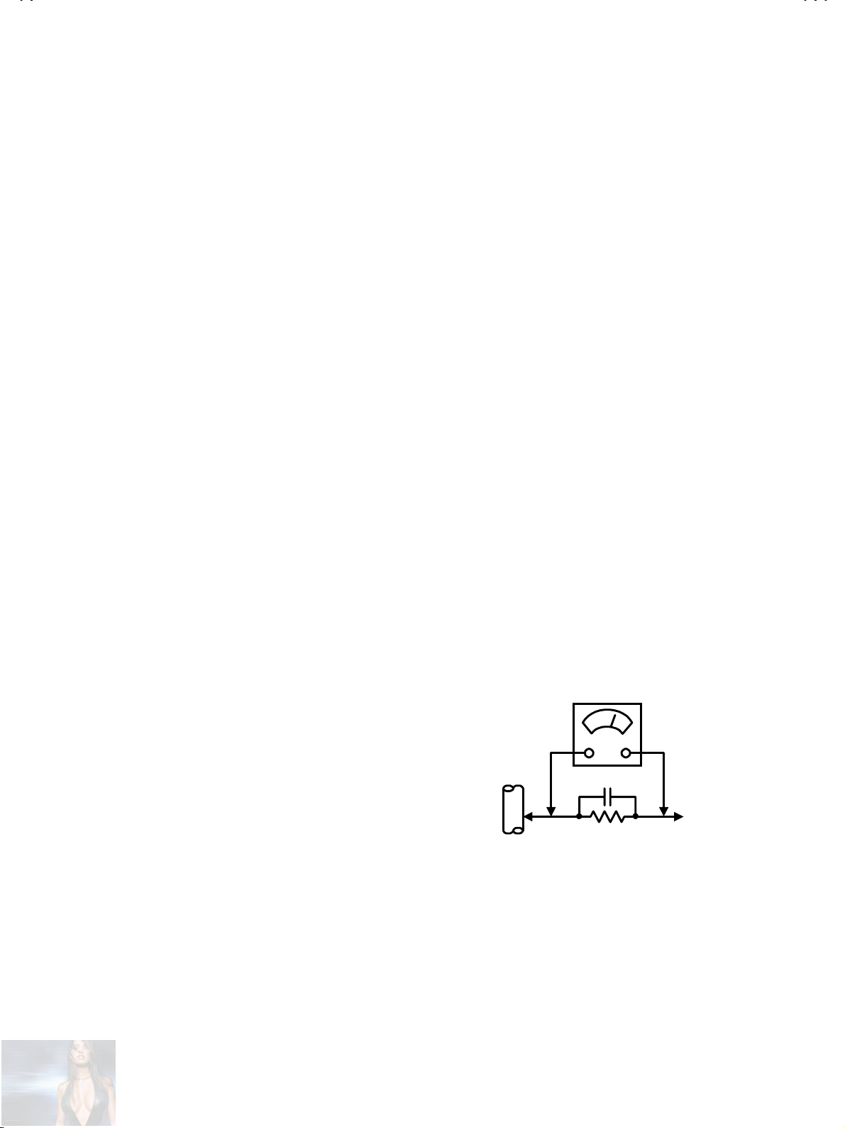
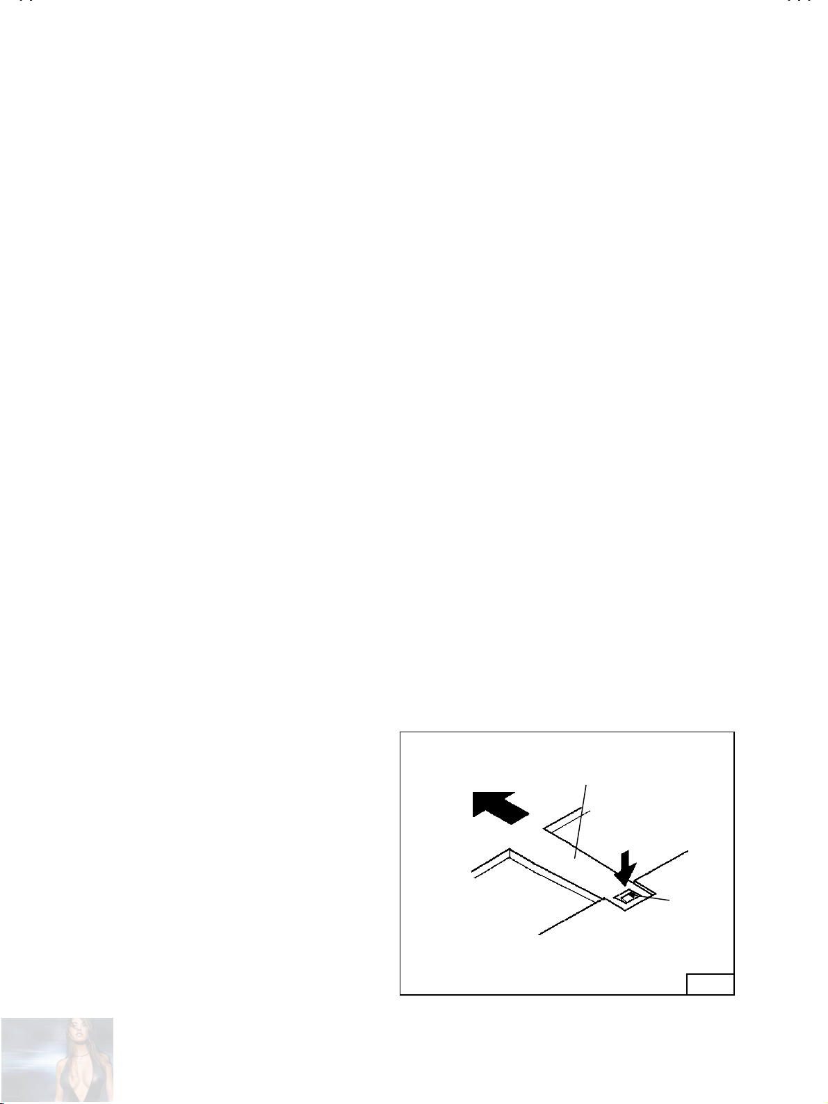
Alternate Check Method
""""
Plug the AC lin e c or d dir ec t l y int o t he AC outlet ( d o not use a line
isolati on transform er during t his check. ). Use an AC voltmet er
having 1000 ohms per volt or more sensitivity in the following
manner. Connect a 1 500! 10W resistor paralleled by a 0.15#F
AC-typ e capacitor betw een an expos ed metal part and a know n
good earth ground (water pipe, etc.). Measure the AC voltage
across the resistor with the AC voltmeter. Move the resistor
connect ion t o each exp os ed met al p art, part icul arl y any exp osed
metal part h avin g a return p ath to th e chassis , and meas ure th e
AC voltag e across the res istor. N ow, re vers e the plug in the AC
outlet and repeat each measurement. Any voltage measured
must not exceed 0.75V AC (r.m.s.). This corresponds to 0.5mA
AC (r.m.s.).
However , i n t ropical area, this must n ot exceed 0.3 V AC (r.m.s. ).
This corresponds to 0.2mA AC (r.m.s.).
0.15μF AC-TYPE
1500
GOOD EARTH GROUND
!
AC VOLTMETER
(HAVING 1000
OR MORE SENSITIVITY)
10W
!
/V,
PLACE THIS PROBE
ON EACH EXPOSED
METAL PART
No.51730
3
Page 4
A
V-29RS
FEATURES
By preference, us ers can selec t the picture siz e from REG ULA R,
"
ZOOM, 16:9 modes.
The TELETEXT SYSTEM has a built-in FASTEXT and WST
"
system.
B ecause this TV uni t corresp onds t o multipl ex broadc ast, us ers
"
can enjo y music pr ograms an d spor ting ev ents wit h live real ism.
In additi on, BILINGUAL programs c an be heard in their original
language.
Users c an m ake fun to c onnect th e Dig ital V ideo D isk p layer b y
"
using the component video signal input terminal.
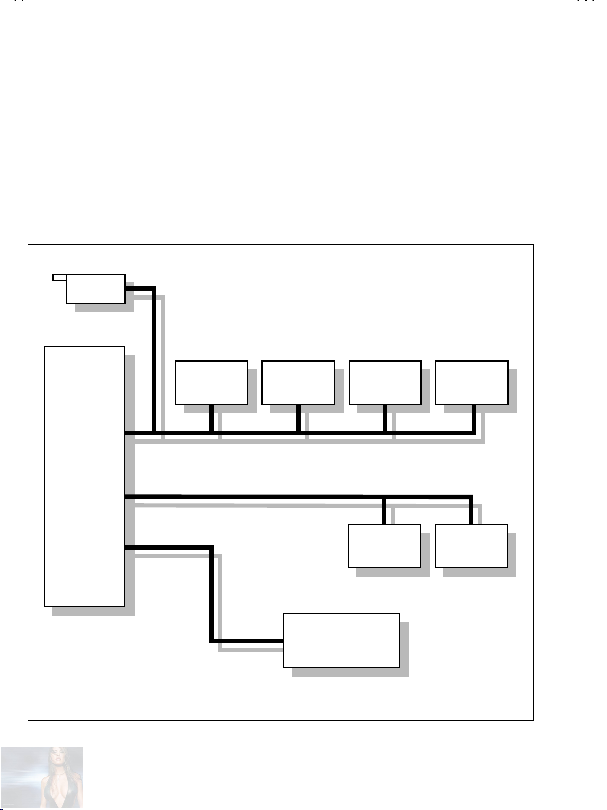
I2C BUS CONTROL SYSTEM CHART
TU1001
TU1001
TUNER
TUNER
IC1301
IC1301
VIDEO
VIDEO
CHROMA
CHROMA
Built-in ECO (ECONOMY, ECOLOGY) MODE.
"
In accordance with the brightness in a room, the brightness
and/or contrast of the picture can be adjusted automatically to
make th e opti mu m picture wh ic h is eas y on the eye.
2
C Bus controls the many ICs which have various functions each
I
"
other.
IC1501
IC1501
DEF CTRL
DEF CTRL
IC1201
IC1201
SRT
SRT
IC8801
IC8801
LED CTRL
LED CTRL
IC1701
IC1701
MICRO
MICRO
COMPUTER
COMPUTER
SCL3 / SDA3
SCL1 / SDA1
SCL2 / SDA2
MEMORY
IC1702
IC1702
MEMORY
IC301 [0S]
IC301 [0S]
DIGI COMB
DIGI COMB
IC101 [0S]
IC101 [0S]
AV SW
AV SW
4
No.51730
Page 5
A
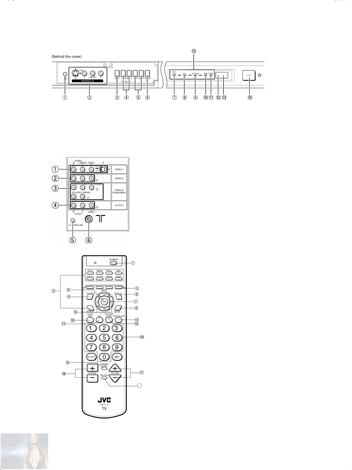
FUNCTIONS
V-29RS
Headphone jack
①
Video-4 terminal
②
OK
③
Channel -/+ (MENUUP/DOW N)
④
Volume -/+ (MENULEFT/RIGHT)
⑤
TV/VIDEO
⑥
AUTO VNR
⑦
ECO
⑧
ON TIMER
⑨
BBE
⑩
Video-1 terminal (S,V,L,R)
①
Video-2 terminal (V,L,R)
②
Video-3 terminal (V/Y,Cb,Cr,L,R)
③
Output terminal (V,L,R)
④
AV COMPULINK terminal
⑤
Aerial socket
⑥
POWER
①
TELETEXT
②
COLOUR
③
TV/VIDEO
④
DISPLAY
⑤
ZOOM
⑥
MENU UP/DOWN
⑦
MENU LEFT/RIGHT
⑧
OK
⑨
AUTO VNR
⑩
AAC
⑪
PICTURE MODE
⑫
SPATIALIZER
⑬
CHANNEL
⑭
CHANNEL SCAN
⑮
CHANNEL +/-
⑯
VOLUME +/-
⑰
MUTING
18
⑱
POWER
⑪
ECO sensor
⑫
Remote control sensor
⑬
Main POWER SW
⑭
Dancing LED
⑮
No.51730
5
Page 6
A
V-29RS
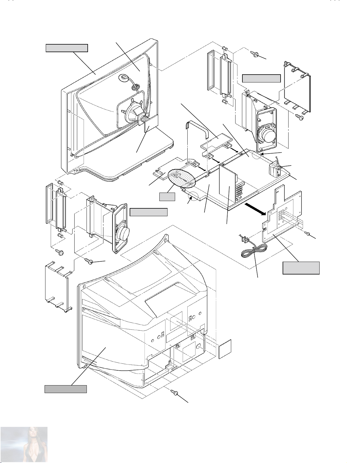
SPECIFIC SERVICE INSTRUCTIONS
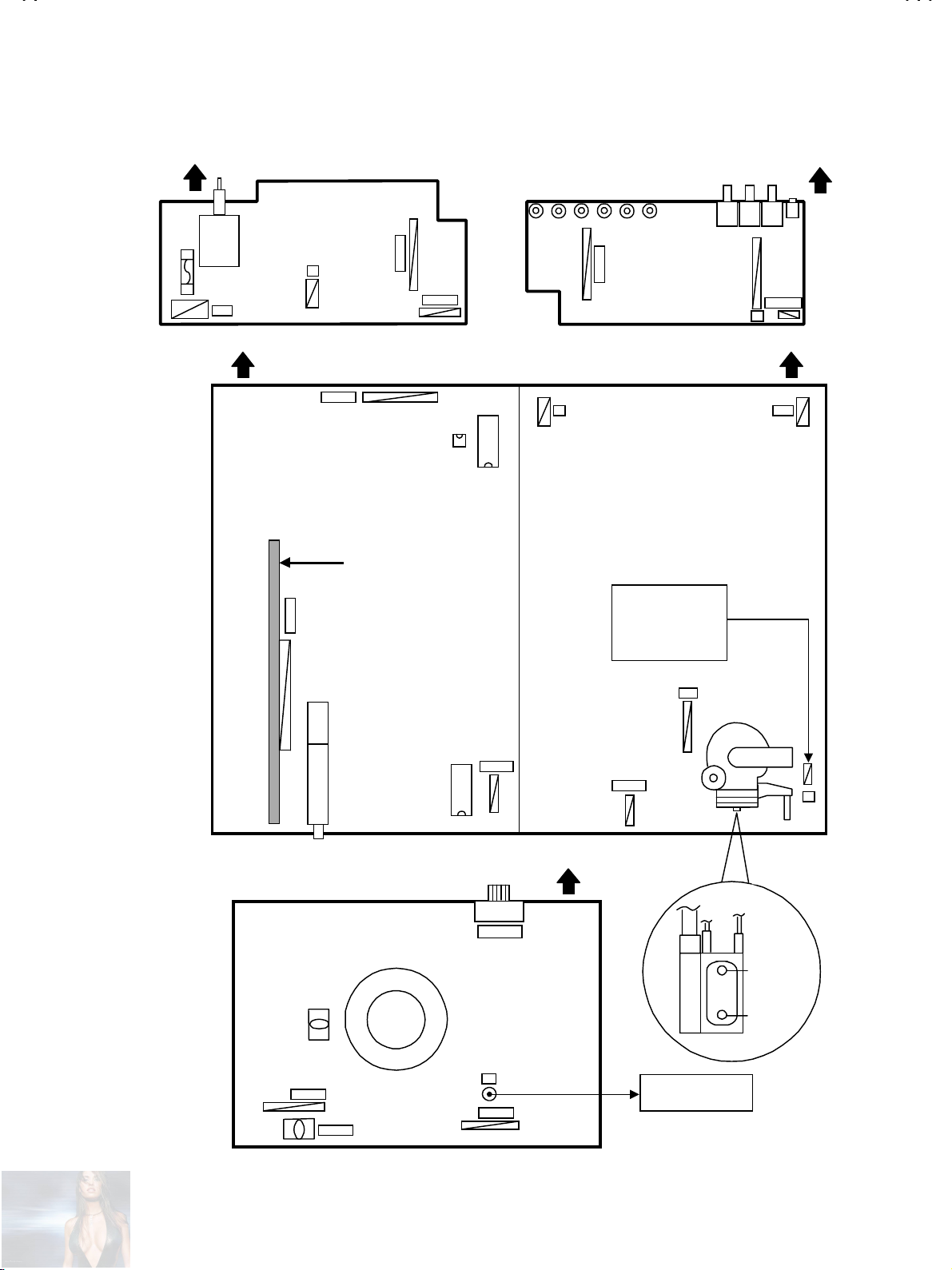
DISASSEMBLY PROCEDURE
REMOVING THE REAR COVER
1. Disconnect the power plug from wall outlet.
2. As shown in the Fig.2, remove the
3. Withdraw the rear cover toward you.
screws marke d
16
AAAA
.
CHECKING THE PW BOARD
To check the PW Board from back side.
1. Pull out the chassis (refer to REMOVING THE CHASSIS).
2. Erect the ch assis ver tic all y s o that you c an easi ly c hec k th e bac k
side of the PW Board.
REMOVING THE CHASSIS
After remo ving the rear cover.
"
1. Slightly raise the both sides of the chassis by hand and remove the
two claws under the both sides of the chassis from the front
cabinet.
2. Withdraw the chassis backward.
(If necessary, take off the wire clamp , connectors etc.)
REMOVING THE AV TERMINAL BOARD
After remo ving the rear cover.
"
1. As shown in Fig.2, remove the
2. Then remove the AV TERMINAL BOARD.
screws marke d
5
BBBB
.
REMOVING THE SPEAKER BOX
After remo ving the rear cover.
"
1. As s hown in Fig. 2, removi ng the
remove the speaker box.
2. Follow the same steps when removing the other hand speaker
box.
When removing the screws marked
NOTE :
remove the lower s ide screw f irst, and th en remove the
upper one.
screws marked
2
of the speaker box,
CCCC
CCCC
then
,
CAUTION
When erecting the chassis, be careful so that there will be no
"
co n tacting w ith oth e r PW Bo ard.
Before turning on power, make sure that the wire connector is
"
properly connected.
When conducting a check with power supplied, be sure to
"
confirm that the CRT EARTH WIRE (BRAIDED ASS
connected to the CRT SOCKET PW board.
’’’’
WIRE CLAMPING AND CABLE TYING
1. Be sure to clamp the wire.
2. Never remove the cable tie used for tying the wires together.
Should it b e inadvertently remov ed, be sure t o tie the wires wit h a
new cable tie.
Y) is
REMOVING THE CONTROL BASE
After removing the cha ssis.
"
1. As shown in Fig.1, while pushing down the claws marked
remove the CONTROL BASE in the arrow direction
6
FFFF
.
,
EEEE
No.51730
FFFF
CONTROL BASE
EEEE
CLAW
CHASSIS
Fig. 1
Page 7
A
FRONT CABINET
(
)
CRT
FRONT CONTROL
PWB
2/2
V-29RS
CCCC
SPEAKER BOX
POWER
DEF P WB
CRT SOCKET PWB
FRONT CONTROL
PWB(1/2)
SPEAKER BOX
CCCC
CLAW
HVT
CHASSIS
BASE
Fig.1
CLAW
MAIN PWB
AV SEL. PWB
BBBB
AV TERMINAL
BOARD
POWER CORD
REAR COVER
AAAA
Fig.2
No.51730
7
Page 8
A
V-29RS
A
A
A
A
A
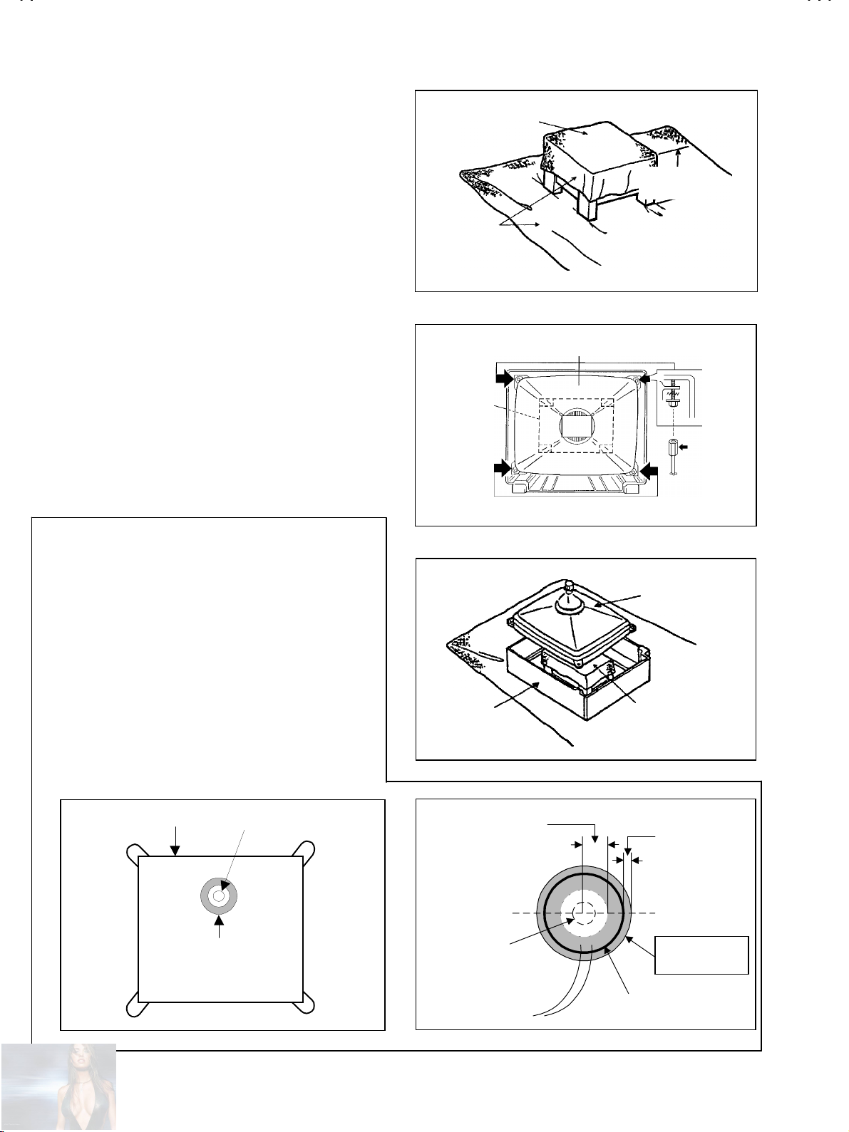
REMOVING THE CRT
Replacement of the CRT should be performed by 2 or more
"
persons.
After removing the cover, chassis etc.,
"
1. Putting the CRT change table on soft cloth, the CRT change table
should also be covered with such soft cloth (shown in Fig.3).
2. While keeping the surface of CRT down, mount the TV set on the
CRT change table balanced will as shown in Fig.3.
3. Remo ve 4 sc r ews m ark ed by arr ows w ith a box type sc rew driver
as shown in Fig.4.
Sinc e the cabin et wi ll dr op wh en sc r ews h ave b een r em oved , b e
"
sure to support the cabinet with hands.
4. After 4 sc rews have been r emoved, p ut the cabin et slowly on
cloth (At this time, be carefully so as not to damage the front
surface of the cabinet) shown in Fig.5.
The CRT should be assembled according to the opposite
"
sequence of its dism oun ting steps.
The CRT c h ang e table s h oul d prefer ab l y b e s m aller th at th e C R T
"
surfac e, and its height b e about 35cm.
CRT CHANGE TABLE
PPROX.
35cm
CLOTH
Fig. 3
CRT
CRT
CHANGE
TABLE
BOX
TYPE
SCREW
DRIVER
COATING OF SILICON GREASE FOR ELECTRICAL
INSULATION ON THE CRT ANODE CAP SECTION.
Subseq uent to r eplacem ent of th e CRT and HV tr ansf ormer or
repair of the anode cap, etc. by dismounting them, be sure t o
coat silicon grease for electrical insul ati on as sh ow n in Fig.6.
Wipe around the anode button with clean and dry cloth. (Fig.6)
Coat silic on greas e on the secti on around th e anode butt on. At
this tim e, t ake c are s o th at any s ilic on gr eases dos e n ot stic k t o
the anode button. (Fig.7)
Silicon grease product No. KS - 650N
CRT
node button
Silicon gr ease
coating
CABINET
pprox.
20mm (Do not
coat grease on
this section
node button
(No sticking of
silicon grease)
Fig. 4
CRT
CRT
CHANGE TABLE
Fig. 5
Silicon gr ease
should b e c oat ed
by 5mm or more
from the outside
diamet er of
anode cap.
Coating position
of silicon grease
node cap
Fig. 6 Fig. 7
8
No. 51730
Page 9
A
REPLACEMENT OF MEMORY ICs
UP/DO
1. Memory ICs
This model uses memory ICs. This memory IC data are for proper
operation of the video and deflection circuits. When replacing, be sure to
use ICs written with the initial values of data.
2. Procedure for replacing memory ICs
(1)
Power off
Switch off th e pow er an d dis connect the power plug from the wall out let .
V-29RS
(2)
Replace the memory IC
Be sure to u se memo ry ICs written with the i nitial data values.
(3)
Power on
Connect the power plu g int o the wall outl et an d s wi tc h power on.
(4)
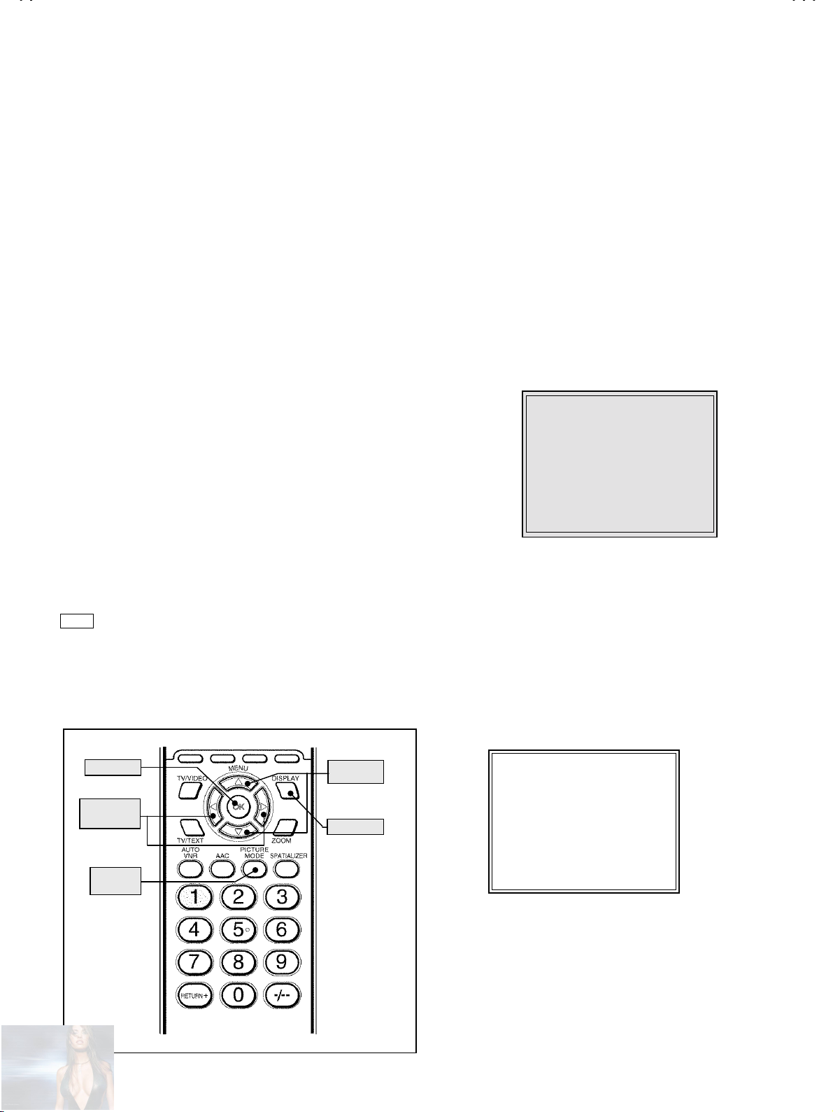
Check and set SYSTEM CONSTANT SET
It must not adjust without signal.
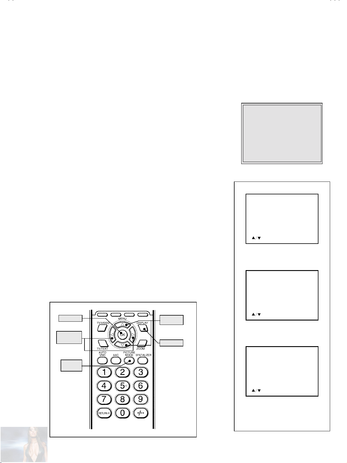
1) Press the
DISPLAY
key and the
PICTURE MODE
key of the REMOTE
CONTROL UNIT simultaneously.
2) T he SERVICE MENU screen of Fig . 1 will be display ed.
3) While the S ERVICE MENU is displ ayed, again press the
PICTURE MODE
key simultaneously, and the SYSTEM CONSTANT SET
DISPLAY
screen of Fi g. 2 will be displa yed .
4) Ch eck the setting val u es of th e SYSTE M CO NSTAN T SE T of Table 1 i n p age
later. If th e value is dif ferent, select the setting it em with th e
key, and set the correct value with the
MENU LEFT/RIGHT
MENU UP/DOWN
key.
5) Press the OK key to memorize the setting value.
6) Press the
(5)
Receive channel s ett in g
DISPLAY
key twice, and return to the normal screen.
Refer to the OPERATING INSTRUCTIONS, and set the receive channels as
described.
(6)
User setti n gs
Check the user setting items according to Table 2. Where these do not agree, refer
to the OPERATING INSTRUCTIONS.
(7)
SERVICE MENU setting
Verif y what to s ee in th e SERVICE MEN U, an d s et wh at e ver in nec es sary.
KEY ASSIGNMENT OF REMOTE CONTROL UNIT
key and
SERVICE MENU
SERVICE MENU
1. IF 2. V/C
3. AUDIO 4. DEF
5. VSM PRESET 6. WB PRESET
7. AUTO PROGRAM (OFF)
1-7 : SELECT DISP : EXIT
M
*******-**** V*.**P
JVC JK BASIC V
**
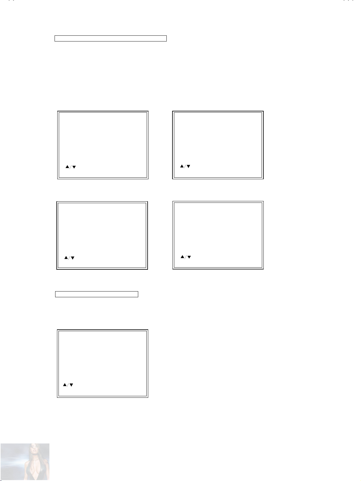
Fig.1
SYSTEM CONSTANT SET 1/3
COLOUR : MULTI
MSP : YES
SUPER BASS : NO
CENTER SPEAKER : NO
TEXT : YES
:SEL -/+:OPE DISP:EXIT
SYSTEM CONSTANT(1/3)
SYSTEM CONSTANT SET 2/3
BLUE BACK MUTE : NO
VOLUME LIMIT : YES
COLOUR AUTO : NO
TILT : YES
C-TRAP : 1
OK
MENU
LEFT/RIGHT
PICTURE
MODE
MENU
WN
DISPLAY
No. 51730
:SEL -/+:OPE DISP:EXIT
SYSTEM CONSTANT(2/3)
SYSTEM CONSTANT SET 3/3
E.M.C : NO
N/S WHITE BACK : NO
7 LED SPEED : 100
:SEL -/+:OPE DISP:EXIT
SYSTEM CONSTANT(3/3)
Fig.2
9
Page 10
A
V-29RS
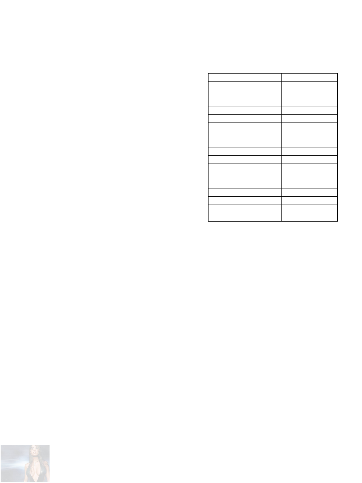
INITIAL SETTING VALUES OF SYSTEM CONSTANT SET (TABLE 1)
CONTENTS VARIABL E RANGE INI TIAL SETTING VALUE
COLOUR
MSP
SUPER BASS
CENTER SPEAKER
TEXT
BLUE BACK MUTE
VOLUME L IMIT
COLOUR AUTO
TILT
C-TRAP
E.M.C
N/S WHITE BACK
7 LED SPEED
MULTI TRIPLE PAL
YES NO
YES NO
YES NO
YES NO
YES NO
YES NO
YES NO
YES NO
1 0
YES NO
YES NO
00 10 20 1250 1260 1270
……
MULTI
YES
NO
NO
YES
NO
YES
NO
YES
1
NO
NO
100
USER SETTING CONDITIONS (TABLE2)
PICTUIRE SETTING FEATURES
CONTRAST
BRIGHT
SHARP
COLOUR
TINT
WHITE BALANCE
A.A.C
AUTO VNR
COLOUR SYSTEM
ZOOM
ECO SENSER
PICTURE TILT
STEREO /
BASS
TREBLE
BALANCE
AI VOLUME
BBE
SPATIALIZER
Ⅰ・Ⅱ
PICTURE FEATURES
SOUND SETTING
CENTER
COOL
ON
AUTO
TV : According to preset CH
VIDEO : AUTO
REGULAR
ACTIVE
CENTER
CENTER
ON
ON
ON
SLEEP TIMER
ON TIMER
BLUE BACK
CHILD LOCK
CHANNEL GUARD
AUTO SHUT OFF
VIDEO-3 SETTING
LANGUAGE
AUTO PROGRAM
EDIT / MANUAL
DEMO OFF
OFF
ON
OFF
OFF
VIDEO
INSTALL
ENGLISH
PRESET CH only
Others : blank
DEMO
10
No. 51730
Page 11
A
SERVICE MENU SETING I TEMS ( TABLE 3)
Setting item Setting value Setting item Setting value
V-29RS
1. IF VCO 4. DEF
2. V / C
1. CUT OFF (R, G, B)
2. DRIVE ( R, B)
3. BRIGHT
4. CONT.
5. COLOUR
6. TINT
7. BLACK OFFSET (R-Y, B-Y)
8. SHARP
5. VSM PRESET
BRIGHT
STANDARD
NORMAL
1. V-SHIFT
2. V-SIZE
3. SUBTITLE
4. H-CENT
5. H-SIZE
6. EW- PIN
7. TRAPEZ
8. EW. COR. L
9. EW. COR. H
10. V. S-COR
11. V-LIN
12. H-BLK-R
13. H-BLK-L
14. V-EHT
15. H-EHT
16. EHT-G AIN
1. BRIGHT
2. CONT
3. COLOUR
4. SHARP
5. TINT
1. AUDIO
(Do not adjust)
1. ERROR LIMIT
2. A2 ID THR
3. BASS
4. TREBLE
6. WB PRESET
COOL
MID
WARM
7. AUTO PROGRAM
(Do not adjust)
No. 51730
1. R DRIVE
2. B DRIVE
ON / OFF
11
Page 12
A
V-29RS
REPLACEMENT OF CHIP COMPONENT
CAUTIONS
!
1. Avoid heating for more than 3 seconds.
2. Do not rub the electrodes and the resist parts of the pattern.
3. When removing a chip part, melt the solder adequately.
4. Do not reuse a chip p art aft er rem oving it.
SOLDERING IRON
!
1. Use a high insulati on soldering iron with a thin p ointed end of it.
2. A 30w soldering iron is recommended for easily removing parts.
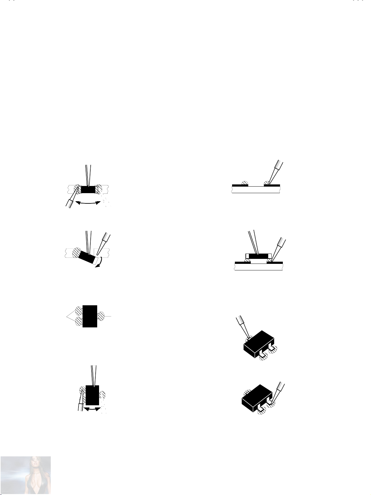
REPLACEMEN T STEPS
!
How to remove Chip parts
1.
Resistors, capacitors, etc
####
(1) As shown in the figure, push the part with tweezers and
alternately melt the solder at eac h end.
(2) S hif t wi th tweezers an d rem o ve t h e ch ip p ar t.
Transistors, diodes, variable resistors, etc
####
(1) Apply extra solder to each lead.
SOLDER
SOLDER
2. How t o i nst al l Chip p arts
Resistors, capacitors, etc
####
(1) Apply solder to the pattern as indicated in the figure.
(2) Grasp th e chip part with tw eezers and pl ace it on th e sold er.
Then heat an d m elt t h e s old er at b oth en ds of th e chip part .
Transistors, diodes, variable resistors, etc
####
(1) Apply solder to the pattern as indicated in the figure.
(2) Grasp the chip part with tweezers and place it on the solder.
(3) First solder lead
as indicated in the figure.
A
A
(2) As shown in the figure, push the part with tweezers and
alternat el y melt t he s old er at each lead . Shif t and r emov e th e
chip part.
Note : After removing the part, remove remaining solder from the
pattern.
12
No. 51730
(4) Then solder leads
and C.
B
C
A
C
B
B
Page 13
A
SERVICE ADJUSTMENTS
BEFORE STARTING SERVICE ADJUSTMENT
1.
There are 2 ways of adjusting this TV: One is with the
REMOTE CONTRO L UNIT and t he oth er is t he conv ention al
method using adjustment pa rts and components.
2.
The adjustment with the REMOTE CONTROL UNIT is made
on the basis of the init ial sett ing valu es . The set tin g val ue s
which adjust the screen t o it s o pt i mum cond ition may differ
from the initial setting values.
3. Make sure that connection is correctly made to AC power
source.
4. Turn on the p ower of the set and eq uipment before use, and
start the adjustment procedures after waiting at least 30 minutes.
5. Unl ess other wis e specifi ed, prep are the mos t suitab le rec eption
or input signal for adjustment.
6. Never touc h any adjus tm ent par ts, whic h are not spec ifi ed in the
list for this adjustment variable resistors, transforms, condensers,
etc.
7. Preparation for adjustment (presetting)
Unless oth erwise sp ecified in t he adjust ment items , preset t he
following functions with the REMOTE CONTROL UNIT.
User mode set ting condition
PICTURE MODE (VSM) STANDARD
WHITE BALANCE MID
ZOOM REGULAR
CONTRAST CENTER
BRIGHT CENTER
SHARP CENTER
COLOUR CENTER
A.A.C OFF
AUTO VNR OFF
PICTURE TILT CENTER
BLUE BACK O FF
AUTO SHUTOFF OFF
ECO SENSOR OFF
AI VOLUME OFF
BBE OFF
SLEEP TIMER OFF
BALANCE CENTER
SPATIALIZER OFF
V-29RS
MEASURING INSTRUMENT AND FIXTURES
1. DC voltme t er (or digital voltmeter)
2. Oscilloscope
3. Signal ge nerator (Pattern genera tor) [PAL / SECAM / NTSC]
4. Remote control unit
ADJUSTMENT CONTENTS
CHECK OF B1 POWER SURPLY
●
CHECK OF HIGH VOLTAGE
●
FOCUS ADJUSTMENT
●
CHECK OF IF CIRCUIT
●
SETTING OF VSM PRESET
●
SETTING OF WHITE BALANCE PRESET
●
VIDEO / CHROMA CIRCUIT ADJUSTMENT
●
DEFLECTION CIRCUIT ADJUSTMENT
●
AUDIO CIRCUIT ADJUSTMENT
●
PURITY, CONVERGENCE ADJUSTMENT
●
[Do not adjust]
No. 51730
13
Page 14
A
V-29RS
UP/DO
BASIC OPERATION OF SERVICE MENU
1. The adjustment using SERVICE MENU
The followi ng adjustm ent items us e the SERVICE ME NU in the seri es of the adjust ment. The adjus tments are made on the basis of the
initial setting values. The adjustment values which adjust the screen to the optimum condition can be different from the initial setting values.
With the SERVICE NEMU, various settings can be made, and they are broadly classified in the following items of settings.
IF
・・・・・・・・・・・・・・・・・・・・・・・・・
V/C
・・・・・・・・・・・・・・・・・・・・・・・
AUDIO
・・・・・・・・・・・・・・・・・・・・
DEF
・・・・・・・・・・・・・・・・・・・・・・・
VSM PRESET
WB PRESET
AUTO PROGRAM
・・・・・・・・・・・・・・
・・・・・・・・・・・・・・・
・・・・・・・・・・・
Adjustment of the IF circuits.
Adjustment of the VIDEO/CHROMA circuit.
Adjustment o f the sound circuit
[Do not ad just]
.
Adjustm en t of th e DEFLECTIO N circ u it f or eac h aspect mod e gi ven below
REGULAR (50/60Hz)
ZOOM (50/60Hz)
16:9 (50/60Hz)
Adjustm en t of th e initial setting values of VS M c on dition as BRIG H T , ST AN D AR D an d S O FT .
(VSM : Video Status Memory)
Adjustment of the initial setting value of WHITE BALANCE PRESET values as COOL, MID and WARM.
By turning the power switch on, you can get the state of AUTO PROGRAM
[Do not adjust ]
.
2. Key operation of the SERVICE MENU
[Enter to SERVICE MENU]
Press the
DISPLAY
key and th e
PICTURE M ODE
key of the REMOTE CONTROL
UNIT simultaneously. Then enter the SERVICE MENU mode as shown in Fig.1.
[Exit from SERVICE MENU]
When c omplet e the ad just ment work, pr ess th e
SERVICE MENU. And then press the
DISPLAY
DISPLAY
key to return to the main
key again, return to the normal
screen.
[Select the SUB MENU from MAIN MENU]
In main SERVICE MENU, press the 1~7 key of the remote control unit, to select any
of the adjustment items.
The colours which selected item characters are changed.
[Method of setting]
1. IF
[VCO]
1 Key
①
②
③
・・・・・・・・・・
The VCO (CW) screen will be displayed.
DISPLAY Key
Selec t
As you press t his k ey, y ou w il l r eturn to the
・・・
1.IF
.
SERVICE MENU
KEY ASSIGNMENT OF REMOTE CONTROL UNIT
OK
MENU
LEFT/RIGHT
MENU
WN
DISPLAY
1. IF 2. V/C
3. AUDIO 4. DEF
5. VSM PRESET 6. WB PRESET
7. AUTO PROGRAM (OFF)
.
SUB MENU 1.IF(VCO)
VCO (CW)
TOO HIGH
ABOVE REFERENCE
JUST REFERENCE
BELOW REFERENCE
TOO LOW
SERVICE MENU
SERVICE MENU
SERVICE MENU
1-7 : SELECT DISP : EXIT
M
*******-**** V*.**P
JVC JK BASIC V
**
Fig.1
**....**
**
****
****
MHz
**
14
DISP: EXIT
PICTURE
MODE
No. 51730
Page 15
A
V-29RS
2.V/C, 4.DEF, 5.VSM PRESET
2, 4, 5, 6 Key
①
MENU UP/DOWN Key
②
MENU LEFT/RIGHT
③
OK Key
④
DISPLAY Key
⑤
・・・・・・・・・・・・・・・・・・
・・・・・・・・・・
・・・・・・・・・・・・
・・・・・・・・・・・・・・・・・・・・・・・
・・・・・・・・・・・・・・・・・・
SUB MENU 2.V/C
V/C 50Hz PAL
1. CUT OFF (R)
- + : OPERATE DISP : EXI T
(G)
(B)
:SELECT
- **
- **
- **
SUB MENU 5.VSM PRESET
VSM PRESET
STANDARD
and
6.WB PRESET
Select on e from
Select setting items.
Set (adjust) the setting values of the setting items.
Memorize the setting value.
(Before storing the setting values in memory, do not press the CH, TV, POWER ON / OFF key -
if you do, the values will not be stored in memory.)
Return to the
2. V/C, 4. DEF, 5. VSM PRESET
SERVICE MENU
screen.
SUB MENU 4.DEF
**
**
DEF
- + : OPERATE DISP : EXIT
Hz
****
1. V-SHIFT
:SELECT
***
(**)
SUB MENU 6.WB PRESET
WB PRESET
MID
and
6.WB PRESET
.
1.BRIGHT
:SELECT
- + : OPERATE DISP : EXIT
3.AUDIO
and
(Do not adjust)
3.AUDIO
7.AUTO PROGRAM
***
7.AUT O PR OGRAM
(Do not adjust)
SUB MENU 3.AUDIO
AUDIO
1. ERROR LIMIT
C_AD_BITS = 00000000
:SELECT
- + : OPERATE DISP : EXIT
・・・・・・・・・・・・・・・・・
・・・・・・・・
***
H
1.R DRIVE
:SELECT
- + : OPERATE DISP : EXI T
***
It is no requirement to adjustmen t.
AUTO PROGRAM contents displays on the screen. Need not for service.
No. 51730
15
Page 16
A
V-29RS
(
)
(
)
)
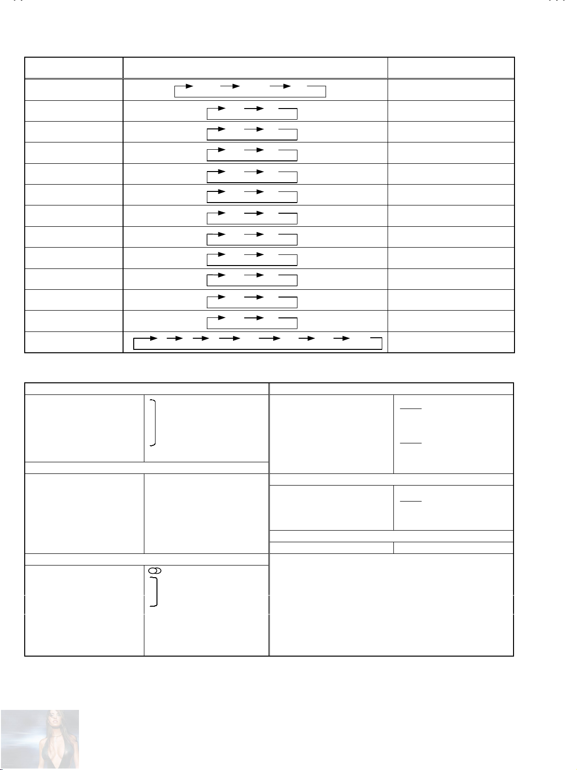
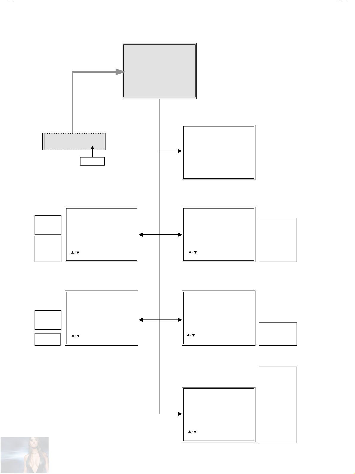
SERVICE MENU FLOW CHART
SERVICE MENU
SERVICE MENU
1. IF 2. V/C
3. AUDIO 4. DEF
5. VSM PRESET 6. WB PRESET
7. AUTO PROGRAM (OFF)
1-7 : SELECT DISP : EXIT
M
*******-**** V*.**P
JVC JK BASIC V
**
7.AUTO PROGRAM (OFF
VSM PRESET STANDARD
BRIGHT
STANDARD
SOFT
1. BRIGHT
2. CONT.
3. COLOUR
4. SHARP
5. TINT
COOL
MID
WARM
1. R DRIVE
2. B DRIVE
- + : OPERATE DISP : EXIT
- + : OPERATE DISP : EXIT
SUB MENU 1. IF
ON/OFF
TOGGLE SWITCH
VCO (CW)
TOO HIGH
ABOVE RE FE RE NCE
JUST REFERENCE
BELOW REFERENCE
TOO LOW
**
** ....**
**
****
****
DISP: EXIT
SUB MENU 5. VSM PRESET SUB MENU 2. V/ C
V/C 50Hz PAL
1.BRIGHT
:SELECT
***
SUB MENU 6. WB PRESET
WB PRESET MID
1.R DRIVE
:SELECT
***
1. CUT OFF (R)
- + : OPERATE DISP : EXIT
:SELECT
(G)
(B)
SUB MENU 3. AUDIO
AUDIO
1. ERROR LIMIT
C_AD_BITS = 00000000
:SELECT
- + : OPERATE DISP : EXIT
VCO
MHz
- **
- **
- **
Do not adjust
H
***
1. CUT OFF
2. DRIVE
3. BRIGHT
4. CONT.
5. COLOUR
6. HUE
7. BLACK OFFSET
8. SHARP
9. PURITY
1. CONC LIMIT
2. A2 ID THR
4. BASS
5. TREBLE
1. V-SHIFT
2. V-SIZE
SUB MENU 4. DEF
DEF
Hz
**
**
****
1. V-SHIFT
:SELECT
- + : OPERATE DISP : EXIT
16
No. 51730
***
(**)
3. SUBTITLE
4. H-CENT
5. H-SIZE
6. EW -PIN
7. TRAPEZ
8. EW .CO R.L
9. EW .CO R.H
10. V.S-COR
11. V-LIN
12. H-BLK-R
13. H-BLK-L
14. V-EHT
15. H-EHT
16. EHT-GAIN
Page 17
A
ADJUSTMENT LOCATIONS
)
(
)
V-29RS
FRONT
POWER
F901
FRONT CO NTROL PW B (1/2)
SW
W
PW
FRONT
CN002
MAIN PWB POWER&DEF PWB
CN001
AV SEL. PWB
CN006
CN001
MEMORY
IC702
IC701
FRONT CO NTROL PW B (2/2)
CN002
F
W DEG
1PIN : B1(TP-91
2PIN : NC
3PIN : NC
4PIN : NC
5PIN : GND
FRONT
CN013
FRONT
TUNER
CRT SOCKET PWB
(SOLDER SIDE)
CN008
TP-E
IC301
CN008
FOCUS
E1
CN009
TOP
CN009
CRT EARTH
BRAIDED WIRE
HV
1
5
X
FOCUS1
SCREEN1
No. 51730
17
Page 18
A
V-29RS
ADJUSTMENTS
CHECK ITEMS BEFORE ADJUSTMENTS
Item
Check of B 1
Power Supply
Measuring
instrument
Signal
generator
DC voltmeter
Test point Adjustment part Description
TP-91(B1)
TP-E(
)
####
[X Connector
on POWER
DEF P WB]
1. Input the bl ac k an d wh it e si gn al.
2. Select 2. V/C from the SERVICE MENU.
3. Select 1. CUT OFF with MENU UP / DOWN key.
4. Show one hori z ontal line by pressing th e 1 key.
5. Turn the SCREEN VR until not to display the one horizontal line.
6. Connect the DC voltmeter to TP-91(B1) and TP-E(#).
7. Make sure that the voltage is DC134.0 ±2.0V.
8. Readjust the SCREEN VR to app ear the hori zontal lin e faintl y,
and cancel the horiz on t al line by pressi ng th e 2 k ey.
Check of Hi gh
Voltage
Signal
generator
High voltage
meter
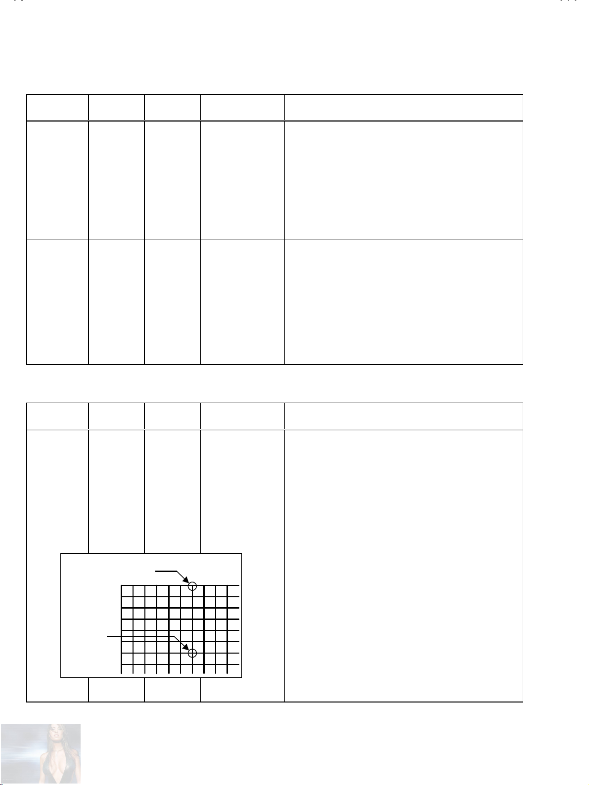
FOCUS ADJUS TMENT
Item
Adjustment of
FOCUS
Measuring
instrument
Signal
generator
CRT anode
Test point Adjustment part Description
FOCU S 1 [In FBT]
FOCUS 2
[CRT SOCKET PWB]
1. Input t h e bl ac k an d wh it e si gnal.
2. Select 2. V/C from the SERVICE MENU.
3. Select 1. CUT OFF with MENU UP / DOWN key.
4. Show on e hor i z ont al line by press in g the 1 key.
5. Turn the SCREEN VR until not to display the one horizontal line.
6. Connect a High voltage meter to CRT ANODE.
7. Make sure that the voltage is DC 32.0kV±1.5kV.
8. Readjust the SC REEN VR to app ear th e horiz ontal line faintl y,
and cancel the horizontal line by pressing 2 key.
1. Input the cross-hatch signal.
2. By turni ng the FOCU S 1 VR, ad just the pic ture s o that th e 7th
horizontal line from the upper side of the cross-hatch picture
becomes thinnest.
3. By turni ng the FOCU S 2 VR, ad just the pic ture s o that th e 7th
vertical line from the left side may become uniform at the line
center and its p er ip h ery.
4. Carry out adjus tment by repeating the steps 2 and 3 ab ov e.
5. Make sure t h at when t h e sc r een is darkened, the lines remain i n
good focus.
FOCUS 2
FOCUS 1
18
No. 51730
Page 19
A
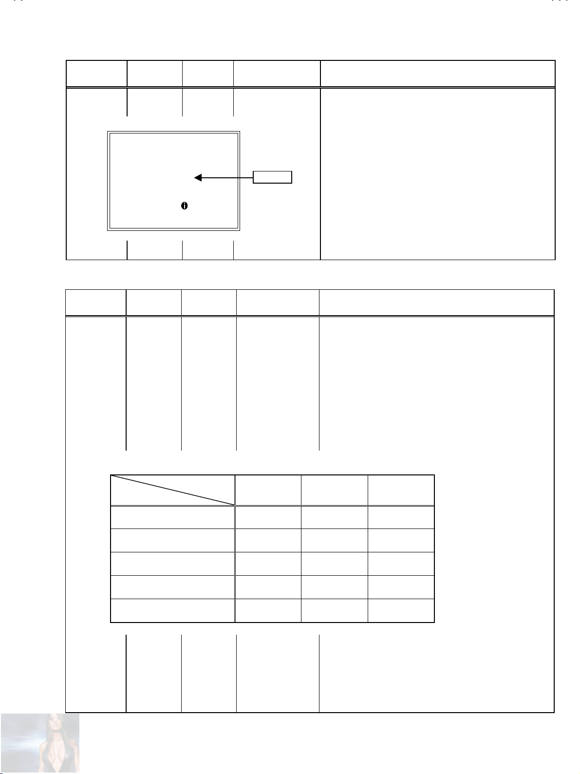
CHECK OF IF CIRCUIT
V-29RS
Item
Adjustment of
VCO
Measuring
instrument
Remote
control unit
VCO (CW)
TOO HIGH
ABOVE REFERENCE
JUST REFERENCE
BELOW REFERENCE
TOO LOW
**
**....**
****
SETTING OF VSM PRESET
Item
Setting of
VSM PRESET
Measuring
instrument
Remote
control unit
Test point Adjustment part Descrip tion
Under normal conditions, it is no adjustment required.
1.IF
MHz
**
****
YELLOW
: EXIT
Test point Adjustment part Description
5.VSM PRESET
1. BRIGHT
2. CONT.
3. COLOUR
4. SHARP
5. TINT
"
It must not adjus t w ith ou t br oadcast sig n al.
"
1. Selec t 1.IF f rom the S ERVICE MENU, then dis plays t he VCO
adjustment screen.
2. Check the characters colour of the JUST REFERENCE
displayed to yellow.
1. Select 5.VSM PRESET from the SERVICE MENU.
2. Select PICTURE MODE to BRIGHT in the user setting MENU.
3. Adjust the MENU UP/DOWN and -LEFT/RIGHT key to bring the
set valu es of 1.BR IGHT~5. TINT to the values shown in the
table.
4. Press the OK key and memorize the set value.
5. Respectively select the PICTURE MODE to STANDARD and
SOFT, and m ak e si milar sett in g as in 3 abo ve.
6. Press the OK key and memorize the set value.
[INITIAL SETTING VALUES OF VSM PRESET]
PICTURE MODE
ITEM
1. BRIGHT
2. CONT
3. COLOUR
4. SHARP
5. TINT
BRIGHT STANDARD SOFT
+0 +0 +0
+17 +0 -4
+0 +0 -1
+0 +0 -3
+0 +0 +0
No. 51730
19
Page 20

A
V-29RS
SETTING OF WHITE BALANCE PRESET
Item
Setting of
WHITE
BALANCE
PRESET
[INITIAL SETTING VALUES OF WHITE BALANCE PRESET]
ITEM
Measuring
instrument
Remote
control unit
1. R DRIVE
2. B DRIVE
Test point Adjustment part Description
WHITE BALANCE
6.WB PRESET
1. R DRIVE
2. B DRIVE
COOL MID WARM
0-3+26
0-23-27
1. Select 6.WB PRESET from the SERVICE MENU.
2. Select COOL in the user setting MENU.
3. Adjust the MENU UP/DOWN and LEFT/RIGHT key to bring the
set values of 1.R DRIVE~2.B DRIVE to the values shown in the
table.
4. Press the OK key and memorize the set value.
5. Respectively select the WHITE BALAMCE MODE to MID and
WAR M, and m ak e sim il ar ad jus t m ent as in 3 above.
6. Press the OK key and memorize the set value.
VIDEO / CHROMA CIRCUIT ADJUSTMENT
The setting (adjustment) using the REMOTE CONTROL UNIT is made on the basis of the initial setting values.
The setting values which adjust the screen to the optimum condition can be different from the initial setting values.
CONTENTS PAL SECAM NTSC3.58 NTSC4.43
1. CUTOFF
2. DRIVE
3. BRI GHT
4. CONT
5. COLOUR
6. TINT
7. BLACK OFFSET
8. SHARP
R
G
B
R
B
TV
VIDEO
COMPONENT
TV
VIDEO
COMPONENT
TV / VIDEO
COMPONENT
TV
VIDEO
COMPONENT
R-Y
B-Y
TV
VIDEO
COMPONENT
-60
-60
-60
+0
+0
0+3+1
-1 +2 +2
-2
-15 0 0
000
+2
+10 +18 +0 0
+8 +17
+6 +6 +7 0
+6 +6 +14 0
+6 -13
-
-
-12 -13 -12
-8 -7 -9
0
0
-10
--
--
-
-
-
-
-
-
20
No. 51730
Page 21

A
V-29RS
Item
Adjustment
of WHITE
BALANCE
(Low Light)
H LINE ON
H LINE OFF
R CUTOFF
R CUTOFF
Signal
generator
Remote
control unit
▲▲▲▲
▼▼▼▼
Measuring
instrument
Test point Adjust m ent part Description
1.CUT OFF
R, G, B
SCREEN VR
[In FBT]
G CUTOFF
B CUTOFF
B CUTOFF
G CUTOFF
Set the PICTURE MODE to STANDARD.
"
1. S et the W HIT E BALANCE to COOL.
2. Receive a bl ac k an d w hi t e sig nal (colour off ) .
3. Select 2. V/C from the SERVICE MENU.
4. Select 1.CUT OFF with the MENU UP/DOWN key.
5. Show one hor i z ont al line with th e 1 key.
6. G radually t urn the SC REEN V R from th e left en d to th e right
directi on to bring one of the r ed, green or blue c olour faint ly
visible.
7. Press 4~9 key, an d bring out th e other 2 colou rs and make
one horizontal line visible in white.
8. Turn the SCREEN VR and bring one white horizontal line
faintl y vis i bl e.
9. Press 2 key, tur n off on e hor i z ontal line.
10. Press the OK key and memorize the set value.
▲▲▲▲
▲▲▲▲
▼▼▼▼
▼▼▼▼
Adjustment
of WHITE
BALANCE
(High Light)
DRIVE
DRIVE
R
R
▲▲▲▲
▼▼▼▼
Signal
generator
Remote
control unit
2.DRIVE
DRIVE
DRIVE
R, B
The adjustment for Low Light WHITE BALANCE should be
"
finished.
Set the PICTURE MODE to STANDARD.
"
1. Set the WH IT E BALANCE to COOL.
2. Inp ut th e black and white signal (colour off ).
3. Select 2.V/C from the SERVICE MENU.
4. Select 2.DRIVE with the MENU UP/DOWN key.
5. Change the screen c olour to white with 4 key or 7 key (dri ve of
red), 6 key or 9 key ( drive of blue).
6. Press the OK key, and memorize the set values.
B
▲▲▲▲
B
▼▼▼▼
No. 51730
21
Page 22

A
V-29RS
Item
Adjustment
of
SUB BR I GHT
Adjustment
of
SUB
CONTRAST
Adjustment
of SUB
COLOUR
ⅠⅠⅠⅠ
Measuring
instrument
Remote
control unit
Remote
control unit
Remote
control unit
Test point Adjust m ent part Description
3.BRIGHT
4.CONT.
5.COLOUR [ Adju stm ent meth od wi tho ut meas uring instrument]
PAL COLOUR 1. Receive the PAL broadcast.
1. Receive any broadc ast.
2. Select 2.V/C from the SERVICE MENU.
3. Select 3.BRIGHT with th e MENU UP/D OWN key.
4. Set the initial setting value with the MENU LEFT/RIGHT key.
5. If the brightness is not the best with the initial setting value,
make fin e adj us tm en t unt il y ou g et t h e bes t br ig ht n ess .
6. Press the OK key and memorize the set value.
1. Receive any broadc ast.
2. Select 2.V/C from the SERVICE MENU.
3. Select 4.CONT with the MENU UP/DOWN key.
4. Set the initial setting value with the MENU LEFT/RIGHT key.
5. If the contras t is n ot the bes t with th e ini tial setti ng value, mak e
fine adjustment until you get the best contrast.
6. Press the OK key and memorize the set value.
2. Select 2.V/C from the SERVICE MENU.
3. Select 5.COLOUR with the MENU UP/DOWN key.
4. Set the init ial setting value for PA L COLOUR with th e MENU
LEFT/RIGHT key.
5. If the colour is not the best with the initial set value, make
fine adjustment until you get the best colour.
6. Press the OK key and memorize the set value.
SECAM COLOUR 1. Receive the SECAM broadcast.
2. Select 2.V/C from the SERVICE MENU.
3. Select 5.COLOUR with the MENU UP/DOWN key.
4. Set the initial setting value for SECAM COLOUR with the MENU
LEFT/RIGHT key.
5. If the colour is not the best with the initial set value, make
fine adjustment until you get the best colour.
6. Press the OK key and memorize the set value.
NTSC 3.58 COLOUR
NTSC 4.43 COLOUR
1. Recei ve th e NT SC 3. 58MHz bro adcast.
2. Make similar fine adjustment of NTSC 3.58 COLOUR in the
same manner as for ab ove.
1. When NTSC 3.58 is set, NTSC 4.43 will be aut omatic ally s et at
the respective values.
22
No. 51730
Page 23

A
V-29RS
Item
Adjustment
of SUB
COLOUR
ⅡⅡⅡⅡ
W
Measuring
instrument
Signal
generator
Oscilloscope
Remote
control unit
Y
Cy
G
Test point Adjust m ent part Description
TP-47G
TP-E(
####
[CRT
SOCKET
PWB ]
5.COLOUR [Adjustment method using m ea suri ng instrument]
)
PAL COLOUR 1. Input the PAL full field colour bar signal (with 75% white).
2. Select 2.V/C from the SERVICE MENU.
3. Select 5.COLOUR with the MENU UP/DOWN key.
4. Set the initial s etting value of PAL COLOUR with the MENU
LEFT/RIGHT key.
5. Connect the oscilloscope between TP-47G and TP-E(#).
6. Adjust PAL CO LOUR to br ing the val ue of
to
(Volt ag e differenc e betw e en w hi te (W) and green (G) ).
-3V
7. Press the OK key and memorize the setting value.
B
R
Mg
-
(
)
0V
(A)
(+)
in the illus trati on
(A)
SECAM COLOUR 1. Input the SECAM full field colour bar signal ( with 75% white).
2. S et the init i al setting valu e of SECA M CO LO UR with the MENU
LEFT/RIGHT key.
3. Adjust SECAM COLOUR to bring the value of
illustr ation to
green (G)) .
4. Press the OK key and memorize the setting value.
NTSC COLOUR 1. Input the N TSC 3 .58 MHz full f iel d colou r bar si gnal ( with 75%
white).
2. Set the initial setting value of NTSC 3.58 COLOUR with the
MENU LEFT/RIGHT key.
3. Adjust NT SC 3.5 8 COLOU R and bring t he value of
illustr ation to
green (G)) .
4. Press the OK key and memorize the setting value.
NTSC 4.43 COLOUR
1. When NTSC 3.58 is set, NTSC 4.4 3 will be automat icall y set at
the respective values.
(Voltage difference between white (W) and
-5V
(V olt age di ff eren ce b etwe en w hit e (W ) and
+3V
(A)
(A)
in the
in the
No. 51730
23
Page 24

A
V-29RS
(B)
Item
Adjustment
of
SUB TINT
Adjustment
of
SUB TINT
ⅠⅠⅠⅠ
ⅡⅡⅡⅡ
Measuring
instrument
Remote
control unit
Signal
generator
Oscilloscope
Remote
control unit
Test point Adjust m ent part Description
[Adjustment meth od wi tho ut me as urin g instr u m ent]
1. receive the NTSC 3. 58 MHz broadcast.
2. Select 2.V/C from the SERVICE MENU.
3. Select 6. TINT with the MENU UP/DOWN key.
4. S et the initial s etting val ue of NT SC 3.58 TINT with the ME NU
LEFT/RIGHT key.
5. If you cannot get th e b est tint with t h e initial setting val ue, m ak e
fine adjustment until you get the best tint.
6. Press the OK key and memorize the set value.
1. When NTSC 3.58 is set, NTSC 4.43 will be aut omatic ally s et at
the respective values.
[Adjustment meth od usi ng m ea suri ng instrument]
1. Input th e NTSC 3 .58MHz full fiel d colour bar sign al (with 75%
white).
2. Select 2.V/C from the SERVICE MENU.
3. Select 6. TINT with the MENU UP/DOWN key.
4. Set th e initi al sett ing value of N TSC 3. 58 T INT wit h the MENU
LEFT/RIGHT key.
5. Connect the osc i lloscop e bet w een TP -4 7G an d TP -E (#)
6. Adjust NTSC 3.58 TINT to bring the value of (B) in the
illustr ation to
cyan (Cy)).
7. Press the OK key and memorize the setting value
(volt age diff erenc e between white (W) and
+4V
TP-47G
TP-E(
####
[CRT
SOCKET
PWB]
6. TINT
NTSC 3.58 TINT
NTSC 4.43 TINT
6. TINT
)
NTSC 3.58 TINT
B
R
Mg
(
)
-
0V
W
Y
(+)
Cy
G
NTSC 4.43 TINT
24
No. 51730
1. When NTSC 3.58 is set, NTSC 4.43 will be automatically set at
the respective values.
Page 25

A
V-29RS
Item
Adjustment
Of
SECAM
BLACK
OFFSET-
Adjustment
Of
SECAM
BLACK
OFFSET-
ⅠⅠⅠⅠ
R-Y
R-Y
ⅡⅡⅡⅡ
▲▲▲▲
▼▼▼▼
Measuring
instrument
Remote
control unit
Signal
generator
Oscilloscope
Remote
control unit
Test point A djustm ent part Description
[Method of adjustment without measuring instrument]
1. Receive the SE CAM broadcast.
2. Select 2. V/C from SERVICE MENU.
3. Select 7. BLACK OFFSET with the MENU UP / DOWN key.
4. Set the init ial setting value f or 7. B LACK OFFS ET (R-Y) and
(B-Y) with
5. If the picture is not the best w ith the initial sett ing value, m ake
fine adjus t m ent un til you get the best pic t u r e.
6. Press the OK key and memorise the set value.
[Method of adjustment using measuring instrument]
1. Input the SECAM full field colour bar signal ( with 75% white).
2. Select 2. V/C from SERVICE MENU.
3. Select 7. BLACK OFFSET with the MENU UP / DOWN key.
4. Connect the oscilloscope between
5. By using
OFFSET (R-Y) s o that i t bec om es th e w avef orm c hang es f r om
to
(A)
6. Connect the oscilloscope between
7. By using
OFFSET (B-Y) so that it becomes the waveform changes from
to
(C)
8. If th e pict ure is not th e b est w it h the adjus ted picture, make f in e
adjust m ent un t il you get t h e bes t pic ture.
9. Press the OK key twice to return to the normal screen.
and 7 or 6 and 9 keys of the remote control.
4
and 7 keys of the rem ot e contr ol, ad just th e BLAC K
4
shown in the figure.
(B)
and 9 keys of the rem ot e contr ol, ad just th e BLAC K
6
shown in the figure.
(D)
35 PIN (R-Y)
36 PIN (B-Y)
IC 1301 On
MAIN PWB
[R-Y]
7. BLACK OFFSET
(R-Y)
(B-Y)
B-Y
▲▲▲▲
B-Y
▼▼▼▼
7. BLACK OFFSET
(R-Y)
(B-Y)
pin of IC 1301 and TP -E.
35
pin of IC 1301 and TP -E.
36
(A) (B)
[B-Y]
(C) (D)
No. 51730
25
Page 26

A
V-29RS
DEFLECTION CIRCUIT ADJUST MENT
There ar e 3 modes of th e adjustment ( 1 ) 50H z mode ( ①REGULAR ②ZOOM ③16:9 ), ( 2 ) 60Hz mode ( each aspect mod e )
depending upon the kind of signals ( vertical frequency 50Hz / 60Hz ).
The adjustment using the remote control unit is made on the basis of the initial setting values.
The setting values which adjust the screen to the optimum condition can be different from the initial setting values.
DEFLECTION ADJUSTMENTS INITIAL SETTING VALUE
Initial settin g val ue
Setting item Adjustment name
1. V-SHIFT
2. V-SIZE
3. SUBTITLE
4. H-CENT
5. H-SIZE
6. EW-PIN
7. TRAPEZ
Vertical shift -5 -1 0 +1 0 0
Vertical size +7 -1 +36 +35 -39 -39
Subtitle 0 +1 -7 +7 0 0
Horizontal center -10 +5 -1 -1 0 -1
Horizontal size -12 -1 -4 -4 0 -1
Side pin correction -3 +1 -4 -4 +2 0
Trapez oid al dis torti on c orrec t i on +4 -2 0 -1 0 +1
REGULAR
50Hz 60Hz 50Hz 60Hz 50Hz 60Hz
ZOOM 16:9
・・・・・
8. EW.COR.L
9. EW.COR.H
10.V.S-COR
11.V-LIN
12. H-BLK- R
13. H-BLK-L
14.V-EHT
15.H-EHT
16.EHT-GAIN
Corner pi n c orr ec ti on Low side -2 0 -1 -1 +1 +1
Corner pin correction High side -2 0 0 0 +1 +1
Vertical size correction +1300000
Vertical Linearity +2 -1 -1 - 1 +1 0
Horiz ont al Blanking R ig ht 0 0 0 0 +7 7 0
Horiz ont al Blanking L eft 0 0 0 0 +2 0
V size correction level caused by EHT change -4 0 0 0 0 0
H size correction level caused by EHT change -3 0 0 0 0 0
Size correction gain caused by EHT change +3 0 0 0 0 0
26
No. 51730
Page 27

A
V-29RS
Item
Adjustment
of
V-SHIFT
Adjustment
of V-SIZE
Measuring
instrument
Signal
generator
Remote
control unit
Signal
generator
Remote
control unit
Test point Adjust m ent part Description
1. V- SHIFT
At first, select the ASPECT mode to REGULAR.
●
1. Input the cir c l e p attern signal.
2. Select 4.DEF from the SERVICE MENU.
3. Select 1.V-SHIFT with the MENU UP/DOWN key.
4. Adjust V-SHIFT to make
A = B
.
5. Press th e OK k ey an d m em orize th e s et valu e.
A
B
2.V-SIZE
6. Input the cross-hatch signal.
7. Select 2.V-SIZE and set the initial setting value.
8. Adjust V-SI ZE and make sur e that th e vertic al screen siz e is in
the bellow table.
9. Press the OK key and memorize the set value.
Screen
size
[VERTICAL SIZE]
ASPECT MODE REGULAR ZOOM 16 : 9
Screen size
Picture size 100%
V SIZE
Picture
size
100%
92% 74%
295mm
(90% position)
No. 51730
27
Page 28

A
V-29RS
Item
Adjustment of
H.CENTER
Adjustment
of
H.SIZE
Measuring
instrument
Signal
generator
Remote
control unit
C
Signal
generator
Remote
control unit
Test point Adjustment part Descrip tion
4.H-CENT.
10. Inp ut the circle p attern signal.
11. Select 4.H-CENT and set the initial setting value.
12. Adjust H-CENT to make C=D.
13. Press the OK key and memorize the set value.
D
5.H-SIZE
14. Input the circle p attern signal.
15. Select 5.H-SIZE and set the initial setting value.
16. Adjust H-S IZE an d mak e sur e th at th e horiz ontal sc reen size
of the picture is in the bellow table.
17. Press the OK key and memorize the set value.
Adjustment of
EW-PIN
[HORIZONTAL SIZE]
ASPECT MODE REGULAR ZOOM 16:9
Signal
generator
Remote
control unit
H SIZE
Straight
6.EW-PIN
92% 85% 92%
18. Select 6.EW-PIN and set the initial set ting va lue
19. Adjust EW-PIN and m ake t he 2 nd ver tic al li nes at t he l eft and
right edg es of t h e s c reen str ai ght . A lso make s ure th at th e 3r d
vertical lines are straight.
20. Press the OK key and memorize the set value.
28
No. 51730
Page 29

A
V-29RS
Item
Adjustment
of TRAPEZ
Adjustment of
EW. COR. L/H
Measuring
instrument
Signal
generator
Remote
control unit
Test point Adjust m ent part Descrip tion
7.TRAPEZ
Parallel
Signal
generator
Remote
control unit
8.EW. COR. L
9.EW. COR. H
Straight Straight
21. Input the cross-hatch signal.
22. Select 7.TRAPEZ with the MENU UP/DOWN key.
23. Set the initial setting value of TRAPEZ with the MENU
LEFT/RIGHT key.
24. Adjust T RAPEZ and bring t h e vertical li n es at the right and left
edges of the screen parallel .
25. Press the OK key and memorize the set value.
26. Select 8.EW. COR. L with the MENU UP / DOWN key.
27. Set the initial setting value of EW. COR. L with the MENU
LEFT/RIGHT key.
28. Adjus t E W. CO R . L, and bring the lin e to straig ht at the corn er
of the screen bottom.
29. Select 9.EW. COR. H with the MENU UP / DOWN key.
30. Set the initial setting value of EW . COR. H with the MENU
LEFT/RIGHT key.
31. Adjus t EW. CO R . H, and bri ng the lin e t o s tr aight at t h e c orn er
of the screen top.
32. Press the OK key and memorize the set value.
Adjustment
of V-S.CR &
V.LINEARITY
Signal
generator
Remote
control unit
10. V-S.CR
11. V-LIN
TOP
CENTER
BOTTOM
No. 51730
In case when the vertical linearity has been deteriorated
●●●●
remarkably, perform the following steps.
33. Input the cross-hatch signal.
34. Select 11.V-LIN with the MENU UP/DOWN key.
35. Set the initial setting value of 11.V-LIN with the MENU
LEFT/RIGHT key.
36. Select 10.V-S.CR with the MENU UP / DOWN key.
37. Set the initial setting value of 10.V-S.CR with the MENU
LEFT/RIGHT key.
38. Adjust 11.V-LIN and 10.V-S.CR so that the spaces of each line
on top, cent er an d bottom bec om e uniform.
29
Page 30

A
V-29RS
Item
Measuring
instrument
Test point Adjust m ent part Descri ption
At first the adjustment in 50Hz-REGULAR mode should be
done, then the data for the other aspect mode is corrected in
the respective value at the same time. And confirm the
deflect ion adj ust ment in itial s etti ng valu e in 60H z( N TSC Vid eo
mode ) REGULAR mode. If the adjustment in 50Hz each aspect
mode h as b een don e an d s tored, t h e data for th e same aspect
modes in 6 0Hz is c orrec ted in the r espectiv e value. O nly the
data for th e oth er as p ect mod e in 60Hz is corr ec t ed for itself.
AUDIO CIRCUIT ADJUSTMENT
Do not adjust 3.AUDIO(1. ERROR LIMIT, 2. A2 ID THR, 3. BASS, 4. TREBLE) of the SERVICE MENU as it requires no adjustment.
3. AUDIO [Do not adjust]
Sett ing item Variable range fixed value
1. ERROR LIMIT
000H ~ FF0H
100H
2. A2 ID THR 00H ~ FFH 14H
3. BASS -17 ~ +17 +0
4. TREBLE -17 ~ +17 +0
30
No. 51730
Page 31

A
PURITY, CONVERGENCE ADJUSTMENT
g
g
g
PURITY ADJU STMENT
V-29RS
1. Demagnet ize CRT with the demagnetize r.
2. Loosen the retainer screw of the deflection yoke.
3. R emove the wed g es.
4. Input a green r aster signal fr om the sign al gener ator, an d turn
the screen to green raster.
5. M ove t h e def l ec tion yoke bac k ward.
6. Brin g the long l ug of the pur ity magnets on the sh ort lug an d
position them horizontally. (Fig.2)
7. Adj us t t h e g ap b etween t w o l ugs s o th at th e G R EEN RAST ER
will come into the center of the screen. (Fig.3)
8. Move the defl ection yoke forward, and fix the pos ition of the
deflection yoke so that the whole screen will become green.
9. Insert the wedge to the top side of the deflection yoke so that it
will not move.
WEDGE
CRT
DEF. YOKE
P/C MAGNETS
P : PURITY MAGNET
4 : 4 POLES
6 : 6 POLES
(con ver g ence magnets )
(con ver g ence magnets )
Fig.1
DYNAMIC CONVERGENCE ADJUSTMENT
PURITY MAGNET(P)
46
P / C MAGNETS
PURITY MAGNETS
CRT SOCKET PWB
10. Input a crosshatch signal.
11. Verify that the scr een is horizont al.
12. Inp ut red and blu e raster si gnals, and make su re that pur ity is
properly adjust ed.
Short lu
Bring the long lug over the short lu
and position them horizontally.
Fig.2
(FRONT VIEW)
CENTER
Fig.3
Long lu
GREEN RASTER
No.51730
31
Page 32

A
V-29RS
STATIC CONVERGENCE ADJUSTMENT
1. Input a crosshatch signal.
2. Using 4- pole conver gence magn ets, overlap th e red and bl ue
lines in the center of the screen (Fig.1) and turn them to
magenta (red/blue).
3. Using 6-pole convergence magnets, overlap the magenta
(red/bl ue) and gr een li nes in th e cent er of th e screen and tur n
them to white.
4. R epeat 2 and 3 above, an d m ak e best conver g ence.
After ad jus t m ent , fi x the w ed g e at th e ori gi nal positi on.
●
Fasten the retainer screw of the deflection yoke.
Fix the 6 magnets w ith glu e.
DYNAMIC (periphery) CONVERGENCE
ADJUSTMENT
After adjusting purity & static convergence.
(FRONT VIEW)
Fig.1
(FRONT VIEW)
TOP
1. Move the deflection yoke up and down to adjust the pin cushion
distortion in the screen top and bottom. (See Fig. 2)
2. Move t he d eflec ti on yok e left t o righ t to overl ap the lin es i n t he
periph er y, an d m atc h the Yv.(See Fi g. 3)
3. R epeat the steps 1 an d 3 and obtain an optim um converg ence.
4. Diffe rential coil ADJUSTMENT.
In case wher e the horiz ontal lines of red and blue arou nd the
center of both sides of the picture as shown in Fig. 4, adjust the
X
difference by using the differential coil on the top of the
V
deflection yoke (Fig.5) so as to minimize the X
V coil
X
difference.
V
(FRONT VIEW)
GREEN
RED
YV
(FRONT VIEW)
v
X
BLUE
BLUE(RED)
RED(BLUE)
BOTTOM
Fig.2
Fig.3
BLUE
GREEN
RED
RED
GREEN
BLUE
YV
BLUE
GREEN
RED
GREEN
Fig.5
Fig.4
32
No.51730
Page 33

A
PARTS LIST
CAUTION
V-29RS
The parts identified by the
!
the safety .
The par ts n ot indicated in th is Par ts Lis t and those whic h ar e fil led with lin es
!
P. W. Board Ass'y will not be supplied, but those which are filled with the Parts No. in the Parts No. columns will be supplied.
!
symbol are important for the safety. Whenever replacing these parts, be sure to use specified ones to secure
!
in the Parts No. columns will not be supplied.
ABBREVIATIONS OF RESISTO RS, CAPACITO RS AND TOLE RANCES
RESISTORS CAPACITORS
C R Carbon Resistor C CAP. Ceram ic Capacitor
F R Fusible Resistor E CAP. Electrolytic Capacitor
P R Plate Resistor M CAP. Mylar Capacitor
V R
HV R High Voltage Resistor MF CAP. Metalized Film Capacitor
MF R Metal Film Resisto r MM CAP. Metalized Mylar Capac itor
MG R Metal Glazed Resistor MP CAP. Metalized Polystyrol Capacitor
MP R Metal Plate Resistor PP CAP. Polypropylene Capacitor
Variable Resisto
r
HV CAP. High Voltage Capacitor
OM R Metal Oxide Film Resistor
CMF R Coating Metal Film Resistor TF CAP. Thin Film Capacitor
UNF R Non-Flammable Resistor MPP CAP. Metalized Polypropylene Capacitor
CH V R Chip Variable Resistor TAN. CAP. Tantalum Capacitor
CH MG R Chip Metal Glazed Resistor CH C CAP. Chip Ceramic Capacitor
COMP. R Composition Resistor BP E CAP. Bi-Polar Electrolytic Capacitor
LPTC R
Linear Positive Temperature Coefficient
Resistor
PS CAP
.
CH AL E CAP. Chip Aluminum Electrolytic Capacitor
CH AL BP CAP.
CH TAN. E CAP.
CH AL BP E CAP.
Polystyrol Capacitor
Chip Aluminum Bi-Polar Capacitor
Chip Tantalum Electrolytic Capacitor
Chip Tantalum Bi-Polar Electrolytic Capacitor
TOLERANCES
FGJKMNRHZP
1%
±
2%
±
5%
±
10%
±
20%
±
±
30%
+30%
-10%
+50%
-10%
+80%
-20%
+100%
-0%
No.51730
33
Page 34

A
V-29RS
CONTENTS
USING PW BOARD & REMOTE CONTROL UNIT
!!!!
REMOTE CONTROL UNIT PARTS LIST
!!!!
EXPLODED VIEW PARTS LIST(
!!!!
EXPLODED VIEW (
!!!!
EXPLODED VIEW PARTS LIST (
!!!!
EXPLODED VIEW (
!!!!
PRINTED WIRING BOARD PARTS LIST
!!!!
"
MAIN PW BOARD ASS'Y
"
POWER & DEF PW BOARD ASS' Y
"
CRT SOCKET PW BOARD ASS’Y
"
FRONT CONTROL PW BOARD ASS'Y
"
AV SEL. PW BOARD ASS'Y
PACKING
!
PACKING PARTS LIST
!
・・・・・・・・・・・・・・・・・・・・・・・・・・・・・・・・・・・・・・・・・・・・・・・・・・・・・・・・・・・・・・・・・・・・・・・・・・・・・・・・・・・・・・・・・・・・・・・・・・・・・・
)
ⅠⅠⅠⅠ
・・・・・・・・・・・・・・・・・・・・・・・・・・・・・・・・・・・・・・・・・・・・・・・・・・・・・・・・・・・・・・・・・・・・・・・・・・・・・・・・・・・・・・・・・・・・
)
ⅡⅡⅡⅡ
・・・・・・・・・・・・・・・・・・・・・・・・・・・・・・・・・・・・・・・・・・・・・・・・・・・・・・・・・・・・・・・・・・・・・・・・・・・・・・・・・・・・・・・・・・・・
ⅠⅠⅠⅠ
ⅡⅡⅡⅡ
・・・・・・・・・・・・・・・・・・・・・・・・・・・・・・・・・・・・・・・・・・・・・・・・・・・・・・・・・・・・・・・・・・・・・・・・・・・・・・・・・・・・・・
・・・・・・・・・・・・・・・・・・・・・・・・・・・・・・・・・・・・・・・・・・・・・・・・・・・・・・・・・・・・・・・・・・・・・・・・・・・・・・・・・・・
・・・・・・・・・・・・・・・・・・・・・・・・・・・・・・・・・・・・・・・・・・・・・・・・・・・・・・・・・・・・・・・・・・・・・・・・・・・・・・・・・・・・・・・・
・・・・・・・・・・・・・・・・・・・・・・・・・・・・・・・・・・・・・・・・・・・・・・・・・・・・・・・・・・・・・・・・・・・・・・・・・・
)
・・・・・・・・・・・・・・・・・・・・・・・・・・・・・・・・・・・・・・・・・・・・・・・・・・・・・・・・・・・・・・・・・・・・・・・・・・・・・・・
)
・・・・・・・・・・・・・・・・・・・・・・・・・・・・・・・・・・・・・・・・・・・・・・・・・・・・・・・・・・・・・・・・・・・・・・・・・・・・・・
・・・・・・・・・・・・・・・・・・・・・・・・・・・・・・・・・・・・・・・・・・・・・・・・・・・・・・・・・・・・・・・・・・・・・・・・・・・・
・・・・・・・・・・・・・・・・・・・・・・・・・・・・・・・・・・・・・・・・・・・・・・・・・・・・・・・・・・・・・・・・・・・・・・・・・・・・・
・・・・・・・・・・・・・・・・・・・・・・・・・・・・・・・・・・・・・・・・・・・・・・・・・・・・・・・・・・・・・・・・・・・・・・・・・
・・・・・・・・・・・・・・・・・・・・・・・・・・・・・・・・・・・・・・・・・・・・・・・・・・・・・・・・・・・・・・・・・
34
35
35
35
36
37
38
41
44
45
46
48
48
USING PW BOARD & REMOTE CONTROL UNIT
Model
PWB ASS'Y
MAIN PWB
POWER & DEF PWB
CRT SOCKET PWB
FRONT CONTROL PWB
AV SEL. PWB
REMOTE CONTROL UNIT
AV-29RS
SJK-1003A-H2
SJK-2003A-H2
SJK-3001A-H2
SJK-8011A-H2
SJK0S003A-H2
RM-C112-1H
34
No.51730
Page 35

A
REMOTE CONTROL UNIT PARTS LIST [ RM-C112-1H ]
V-29RS
!
++++++++++++++++++++++++++++++++++++++++++++++++++++++++++++++++++++++++++
++++++++++++++++++++++++++++++++++++++++++++++++++++++++++++++++++++++++++
EXPLODED VIEW PA RTS LI ST (
Ref.No. Part No. Part Name Description
!
12 LC31220-001B INDICATE WINDOW
25 CM48125-009 JVC MARK
26 LC31169-001B-H L.E.D.LENS
27 LC31070-003A-H OPERATION SHEET
37 LC10762-001 B-H FRONT CABINET
!
38 LC20532-003B-H DOOR
39 CM48229-00A-C DOOR LATCH
40 LC31162-001B-H CENTER PLATE
41 LC20585-001 B-H RIGHT PLATE
42 LC31067-001 A-H POWER KNOB
43 CM35235-003-H SPRING
44 LC31165-001B-H LEFT PLATE
ⅠⅠⅠⅠ
)
!"#$%&$ '()*+%&$ '()*+%(," -"./)01*0&2
++3 4!56783695- :;88<!=+>?@<!
++6 4!56<>369A; BCD-<+>?@<!
EXPLODED VIEW (
ⅠⅠⅠⅠ
)
FRONT CABINET
25
27
26
40
!
39
37
12
44
38
41
No.51730
43
42
35
Page 36

A
V-29RS
ⅡⅡⅡⅡ
EXPLODED VIEW PARTS LIST(
Ref.No. Part No. Part Name Description
!
V01 A68LTF356X PICTURE TUBE
!
DY01 QQD0042-001 DEF YOKE
!
L01 QQW0073-001 DEG COIL
!
T2551 QQH0077-002-I2 HVT (SERVICE)
!
1 CHGB0020-0B-FH BRAIDED WIRE
2LC10765-002B-H CONTROL BASE R
!
3 CE41488-00A WEDGE ASSY (×4)
4 CE42388-00A P.C.MAGNET
5 CHFD125-08BD-N FFC WIRE
6LC10764-001 A-H CHASSIS BASE
!
7LC10765-001 B-H CONTROL BASE L
!
8LC10766-001 B-H TERMINAL BOARD
!
9 QYSBSF3012M TAPPING SCREW (×5)For AV BOARD
10 A48457-3-H SPRING
11 QNZ0369-001 ANODE WIRE
!
13 QMP40D0-200J5 POWER CORD
!
15LC10763-002B-H REAR COVER
!
16 LC20377-001B-H RATING LABEL
!
17 QYSBSFG4016Z TAPPING SCREW (×16)
18 CM23167-A01-H CORD CLAMP
!
20 CEBSF10P-03KJ6 SPEAKER (×2)SP01,SP02
22 LC10051 -001A-H DOME COVER (×2)
24 LC10767-001 A-H DOME ADAPTOR (×2)
30 LC40226-001A SPACER (×4)
34 CM34837-A39-H STICK SHEET (×2)
35 CHGB0017-0C BRAIDED SUB ASSY
36 LC10050-001 A-H HORN (×2)
37 LC10762-001 B-H FRONT CABINET
!
)
36
No.51730
Page 37

A
V-29RS
A
EXPLODED VIEW (
!
37
!
!
L01
V01
30
ⅡⅡⅡⅡ
DY01
!
)
11
3
1
!
4
CRT SOCKET
PWB
FRONT
CONTROL PWB
35
10
!
30
24
22
34
36
30
!
5
2
20
7
POWER & DEF
PWB
!
T2551
!
8
34
22
24
30
!
15
36
20
MAIN PWB
V SEL. PWB
!
!
6
9
18
!
13
!
16
17
No.51730
37
Page 38

A
V-29RS
PRINTED WIRING BOARD PA RTS LIST
MAIN PW BOARD ASS’Y (SJK-1003A-H2)
BE,F&G+%&$ '()*+%&$ '()*+%(," -"./)01*0&2
!
++++++++++++++++++++++++++++++++++++++++++++++++++++++++++++++++++++++++++++++++++++
!<BDB8?!
!3HH6IHJ %!B;H6KIH!HL MN+! H$H!+3O3HP+++K
!3HH5IH9 %!B;H6KI3H6L MN+! 3Q!+3O3HP+++K
!3HHR %!B;H6KI3HAL MN+! 3HHQ!+3O3HP+++K
!3H3H %!B;H6KI666L MN+! 6$6Q!+3O3HP+++K
!3H33 %!B;H6KI366L MN+! 3$6Q!+3O3HP+++K
!3H36 %!B;H6KIJJ3L MN+! JJH!+3O3HP+++K
!3H3J %!B;H6KI6RHL MN+! 6R!+3O3HP+++K
!3H3A %!B;H6KI6R3L MN+! 6RH!+3O3HP+++K
!3H35 %!B;H6KI3H6L MN+! 3Q!+3O3HP+++K
!36H3 %!B;H6KI3HAL MN+! 3HHQ!+3O3HP+++K
!36H6 %!B;H6KIARJL MN+! ARQ!+3O3HP+++K
!36HJ %!B;H6KI3SAL MN+! 3SHQ!+3O3HP+++K
!36HA %!B;H6KI66AL MN+! 66HQ!+3O3HP+++K
!36H5 %!B;H6KI59JL MN+! 59Q!+3O3HP+++K
!36H9 %!B;H6KI9S6L MN+! 9$SQ!+3O3HP+++K
!36HR %!B;H6KIJJJL MN+! JJQ!+3O3HP+++K
!36HTI3H %!B;H6KI663L MN+! 66H!+3O3HP+++K
!3653 %!B;H6KIARJL MN+! ARQ!+3O3HP+++K
!3656 %!B;H6KIJT6L MN+! J$TQ!+3O3HP+++K
!365J %!B;H6KIARJL MN+! ARQ!+3O3HP+++K
!365A %!B;H6KI3HJL MN+! 3HQ!+3O3HP+++K
!3655 %!B;H6KIS6JL MN+! S6Q!+3O3HP+++K
!3659 %!B;H6KI666L MN+! 6$6Q!+3O3HP+++K
!365R %!B;H6KIJJJL MN+! JJQ!+3O3HP+++K
!365S %!B;H6KI6R6L MN+! 6$RQ!+3O3HP+++K
!365T %!B;H6KI3H6L MN+! 3Q!+3O3HP+++K
!369H %!B;H6KIS6JL MN+! S6Q!+3O3HP+++K
!3693 %!B;H6KI3H6L MN+! 3Q!+3O3HP+++K
!3696 %!B;H6KI35JL MN+! 35Q!+3O3HP+++K
!369J %!B;H6KI6RJL MN+! 6RQ!+3O3HP+++K
!369A %!B;H6KI3H6L MN+! 3Q!+3O3HP+++K
!3695 %!B;H6KIS63L MN+! S6H!+3O3HP+++K
!3699 %!B;H6KI66JL MN+! 66Q!+3O3HP+++K
!369RI9S %!B;H6KI3H3L MN+! 3HH!+3O3HP+++K
!369T %!B;H6KI3HJL MN+! 3HQ!+3O3HP+++K
!36RH %!B;H6KI9S6L MN+! 9$SQ!+3O3HP+++K
!36R3 %!B;H6KI3HJL MN+! 3HQ!+3O3HP+++K
!3JH3 %!B;H6KIH!HL MN+! H$H!+3O3HP+++K
!3JH6 %!B;H6KI36JL MN+! 36Q!+3O3HP+++K
!3JHA U!NH3NKI363 ?M+! 36H!++++3P+++K
!3JH5 %!B;H6KI596L MN+! 5$9Q!+3O3HP+++K
!3JH9 %!B;H6KI666L MN+! 6$6Q!+3O3HP+++K
!3JHR %!B;H6KI3H6L MN+! 3Q!+3O3HP+++K
!3JHS %!B;H6KIAR3L MN+! ARH!+3O3HP+++K
!3JHT %!B;H6KI666L MN+! 6$6Q!+3O3HP+++K
!3J3HI33 %!B;H6KIJT3L MN+! JTH!+3O3HP+++K
!3J3AI35 %!B;H6KI596L MN+! 5$9Q!+3O3HP+++K
!3J39 %!B;H6KI66AL MN+! 66HQ!+3O3HP+++K
!3J3SI6H %!B;H6KI3H6L MN+! 3Q!+3O3HP+++K
!3J63 %!B;H6KI6R6L MN+! 6$RQ!+3O3HP+++K
!3J69 %!B;H6KI596L MN+! 5$9Q!+3O3HP+++K
!3J6R %!B;H6KI3H3L MN+! 3HH!+3O3HP+++K
!3J6SI6T %!B;H6KI3H6L MN+! 3Q!+3O3HP+++K
!3JJH %!B;H6KIAR6L MN+! A$RQ!+3O3HP+++K
!3JJ3 %!B;H6KI3H3L MN+! 3HH!+3O3HP+++K
!3JJA %!B;H6KI596L MN+! 5$9Q!+3O3HP+++K
!3JJ5 %!B;H6KI6RJL MN+! 6RQ!+3O3HP+++K
!3JJ9 %!B;H6KI3HJL MN+! 3HQ!+3O3HP+++K
!3JJR %!B;H6KI3H6L MN+! 3Q!+3O3HP+++K
!3JJS %!B;H6KI596L MN+! 5$9Q!+3O3HP+++K
!3JJT %!B;H6KIH!HL MN+! H$H!+3O3HP+++K
!3JAHIA3 %!B;H6KI9S3L MN+! 9SH!+3O3HP+++K
!3JA6 %!B;H6KI666L MN+! 6$6Q!+3O3HP+++K
!3JA9 U!<3A3KI3H6= >+! 3Q!++3OAP+++K
!3J53I5J %!B;H6KI6R6L MN+! 6$RQ!+3O3HP+++K
!3J5A %!B;H6KI3H6L MN+! 3Q!+3O3HP+++K
!3J55 %!B;H6KI35JL MN+! 35Q!+3O3HP+++K
!3J59 %!B;H6KI3H6L MN+! 3Q!+3O3HP+++K
!3J5R %!B;H6KI666L MN+! 6$6Q!+3O3HP+++K
!3J5S %!B;H6KI3H6L MN+! 3Q!+3O3HP+++K
BE,F&G+%&$ '()*+%&$ '()*+%(," -"./)01*0&2
!
++++++++++++++++++++++++++++++++++++++++++++++++++++++++++++++++++++++++++++++++++++
!<BDB8?!
!3J5T %!B;H6KIAR6L MN+! A$RQ!+3O3HP+++K
!3J9H %!B;H6KIJT6L MN+! J$TQ!+3O3HP+++K
!3J93 %!B;H6KI3H6L MN+! 3Q!+3O3HP+++K
!3J96 %!B;H6KI366L MN+! 3$6Q!+3O3HP+++K
!3J9JI95 %!B;H6KI36JL MN+! 36Q!+3O3HP+++K
!3J99 %!B;H6KIJT6L MN+! J$TQ!+3O3HP+++K
!3J9RI9S %!B;H6KI3H6L MN+! 3Q!+3O3HP+++K
!3J9TIR3 %!B;H6KI3H3L MN+! 3HH!+3O3HP+++K
!3AH3IH6 %!B;H6KI3HJL MN+! 3HQ!+3O3HP+++K
!3AHJ %!B;H6KI3H6L MN+! 3Q!+3O3HP+++K
!3AHA %!B;H6KI3SJL MN+! 3SQ!+3O3HP+++K
!3AH5 %!B;H6KI66JL MN+! 66Q!+3O3HP+++K
!3A33 %!@;H6-IARJL M7+! ARQ!+3O3HP+++!3A3J %!@;H6-I66JL M7+! 66Q!+3O3HP+++!3A3A %!@;H6-I3H3L M7+! 3HH!+3O3HP+++!3A39 %!B;H6KI3H3L MN+! 3HH!+3O3HP+++K
!3A3R %!B;H6KI3HJL MN+! 3HQ!+3O3HP+++K
!3A3S %!B;H6KI9S6L MN+! 9$SQ!+3O3HP+++K
!3A6H %!B;H6KIR56L MN+! R$5Q!+3O3HP+++K
!3A63 %!B;H6KI3HJL MN+! 3HQ!+3O3HP+++K
!35H3 %!B;H6KI963L MN+! 96H!+3O3HP+++K
!35H6 %!B;H6KI3HJL MN+! 3HQ!+3O3HP+++K
!35HJ %!B;H6KI3HAL MN+! 3HHQ!+3O3HP+++K
!35HA %!B;H6KIS66L MN+! S$6Q!+3O3HP+++K
!35H5IH9 %!B;H6KI663L MN+! 66H!+3O3HP+++K
!35HR %!B;H6KI3H6L MN+! 3Q!+3O3HP+++K
!3539 %!B;H6KIJJ6L MN+! J$JQ!+3O3HP+++K
!353R %!B;H6KIR56L MN+! R$5Q!+3O3HP+++K
!353S %!B;H6KIARJL MN+! ARQ!+3O3HP+++K
!353T %!B;H6KI596L MN+! 5$9Q!+3O3HP+++K
!356H %!B;H6KI356L MN+! 3$5Q!+3O3HP+++K
!3566 %!B;H6KI35JL MN+! 35Q!+3O3HP+++K
!356J %!B;H6KI3HJL MN+! 3HQ!+3O3HP+++K
!356A %!B;H6KI356L MN+! 3$5Q!+3O3HP+++K
!3553 U!V369KI3HHL >+! 3H!++3O6P+++K
!3556 %!B;H6KI36AL MN+! 36HQ!+3O3HP+++K
!355J %!B;H6KI9SJL MN+! 9SQ!+3O3HP+++K
!355A %!B;H6KIJJJL MN+! JJQ!+3O3HP+++K
!3555 %!B;H6KIAR6L MN+! A$RQ!+3O3HP+++K
!3559 %!B;H6KI35AL MN+! 35HQ!+3O3HP+++K
!355RI5S %!B;H6KI596L MN+! 5$9Q!+3O3HP+++K
!355T %!B;H6KIH!HL MN+! H$H!+3O3HP+++K
!359H %!B;H6KI3HAL MN+! 3HHQ!+3O3HP+++K
!3593 U!V369KI3HHL >+! 3H!++3O6P+++K
!35R3 %!B;H6KI3H3L MN+! 3HH!+3O3HP+++K
!35R6 %!B;H6KI3JJL MN+! 3JQ!+3O3HP+++K
!35RJ %!B;H6KIS63L MN+! S6H!+3O3HP+++K
!39HSIHT %!B;H6KIJT6L MN+! J$TQ!+3O3HP+++K
!393HI33 %!B;H6KI3HAL MN+! 3HHQ!+3O3HP+++K
!3936 %!B;H6KI3H3L MN+! 3HH!+3O3HP+++K
!393J %!B;H6KIH!HL MN+! H$H!+3O3HP+++K
!393A %!B;H6KI3H3L MN+! 3HH!+3O3HP+++K
!3935 %!B;H6KIH!HL MN+! H$H!+3O3HP+++K
!3939 %!B;H6KI59JL MN+! 59Q!+3O3HP+++K
!393R %!B;H6KIAR6L MN+! A$RQ!+3O3HP+++K
!393S %!B;H6KI3HJL MN+! 3HQ!+3O3HP+++K
!393T %!B;H6KIJTJL MN+! JTQ!+3O3HP+++K
!396H %!B;H6KI3HJL MN+! 3HQ!+3O3HP+++K
!3963 %!B;H6KIJTJL MN+! JTQ!+3O3HP+++K
!3966 %!B;H6KI366L MN+! 3$6Q!+3O3HP+++K
!396J %!B;H6KIAR6L MN+! A$RQ!+3O3HP+++K
!396A %!B;H6KI59JL MN+! 59Q!+3O3HP+++K
!39A9 %!B;H6KIARJL MN+! ARQ!+3O3HP+++K
!39AR %!B;H6KI6RJL MN+! 6RQ!+3O3HP+++K
!39AS %!B;H6KI3HAL MN+! 3HHQ!+3O3HP+++K
!39AT %!B;H6KI9S6L MN+! 9$SQ!+3O3HP+++K
!395H %!B;H6KI3HAL MN+! 3HHQ!+3O3HP+++K
!395R %!B;H6KIH!HL MN+! H$H!+3O3HP+++K
!399H U!V369KI6!6L >+! 6$6!++3O6P+++K
!3993 %!B;H6KI3HJL MN+! 3HQ!+3O3HP+++K
++++++++++++++++++++++++++++++++++++++++++++++++++++++++++++++++++++++++++++++++++++
38
++++++++++++++++++++++++++++++++++++++++++++++++++++++++++++++++++++++++++++++++++++
No.51730
Page 39

A
V-29RS
BE,F&G+%&$ '()*+%&$ '()*+%(," -"./)01*0&2
!
++++++++++++++++++++++++++++++++++++++++++++++++++++++++++++++++++++++++++++++++++++
!<BDB8?!
!399J %!B;H6KIS66L MN+! S$6Q!+3O3HP+++K
!399A %!B;H6KI596L MN+! 5$9Q!+3O3HP+++K
!39SJ U!V369KI6!6L >+! 6$6!++3O6P+++K
!39SAIS5 %!B;H6KI3H3L MN+! 3HH!+3O3HP+++K
!39ST %!B;H6KIARJL MN+! ARQ!+3O3HP+++K
!39TH %!B;H6KI3H5L MN+! 3M!+3O3HP+++K
!39T3 %!B;H6KI35AL MN+! 35HQ!+3O3HP+++K
!39T6 %!B;H6KIS66L MN+! S$6Q!+3O3HP+++K
!39TJ %!B;H6KI3S6L MN+! 3$SQ!+3O3HP+++K
!39TA %!B;H6KI596L MN+! 5$9Q!+3O3HP+++K
!39T5 %!B;H6KI3H6L MN+! 3Q!+3O3HP+++K
!39T9 %!B;H6KI596L MN+! 5$9Q!+3O3HP+++K
!39TR %!B;H6KI3H6L MN+! 3Q!+3O3HP+++K
!39TSITT %!B;H6KI596L MN+! 5$9Q!+3O3HP+++K
!3R39 %!B;H6KI3H6L MN+! 3Q!+3O3HP+++K
!3R3SI3T %!B;H6KI9S6L MN+! 9$SQ!+3O3HP+++K
!3R66 %!B;H6KIAR6L MN+! A$RQ!+3O3HP+++K
!3R6AI65 %!B;H6KIAR6L MN+! A$RQ!+3O3HP+++K
!3R6R %!B;H6KIAR6L MN+! A$RQ!+3O3HP+++K
!3R6TIJ3 %!B;H6KI663L MN+! 66H!+3O3HP+++K
!3RJ6 %!B;H6KI596L MN+! 5$9Q!+3O3HP+++K
!3RJJ %!B;H6KI3HJL MN+! 3HQ!+3O3HP+++K
!3RJA %!B;H6KI66JL MN+! 66Q!+3O3HP+++K
!3RJ5 %!B;H6KI3H6L MN+! 3Q!+3O3HP+++K
!3RJ9IJR %!B;H6KI3HJL MN+! 3HQ!+3O3HP+++K
!3RJT %!B;H6KI3HJL MN+! 3HQ!+3O3HP+++K
!3RAH %!B;H6KIJJ3L MN+! JJH!+3O3HP+++K
!3RA3IA6 %!B;H6KI3H6L MN+! 3Q!+3O3HP+++K
!3RAJIAA %!B;H6KI3H3L MN+! 3HH!+3O3HP+++K
!3RA5 %!B;H6KIAR6L MN+! A$RQ!+3O3HP+++K
!3RAR %!B;H6KIAR6L MN+! A$RQ!+3O3HP+++K
!3RASI56 %!B;H6KI663L MN+! 66H!+3O3HP+++K
!3R5A %!B;H6KI9SJL MN+! 9SQ!+3O3HP+++K
!3R59 %!B;H6KI3HJL MN+! 3HQ!+3O3HP+++K
!3R5R %!B;H6KIJTJL MN+! JTQ!+3O3HP+++K
!3R5T %!B;H6KIAR6L MN+! A$RQ!+3O3HP+++K
!3R93 %!B;H6KI3HJL MN+! 3HQ!+3O3HP+++K
!3R9J %!B;H6KI3HJL MN+! 3HQ!+3O3HP+++K
!3R9AI99 %!B;H6KI663L MN+! 66H!+3O3HP+++K
!3R9R %!B;H6KI3HJL MN+! 3HQ!+3O3HP+++K
!3R9S %!B;H6KIARJL MN+! ARQ!+3O3HP+++K
!3R9T %!B;H6KIS6JL MN+! S6Q!+3O3HP+++K
!3RRHIRJ %!B;H6KI666L MN+! 6$6Q!+3O3HP+++K
!3RRA %!B;H6KI3HJL MN+! 3HQ!+3O3HP+++K
!3RR5 %!B;H6KI66JL MN+! 66Q!+3O3HP+++K
!3RR9 %!B;H6KI6R6L MN+! 6$RQ!+3O3HP+++K
!3RRRIRT %!B;H6KI666L MN+! 6$6Q!+3O3HP+++K
!3RSH %!B;H6KI3H6L MN+! 3Q!+3O3HP+++K
!3RSA %!B;H6KIARJL MN+! ARQ!+3O3HP+++K
!3RS5 %!B;H6KI66JL MN+! 66Q!+3O3HP+++K
!3RS9 %!B;H6KIARJL MN+! ARQ!+3O3HP+++K
!3RSR %!B;H6KIJJ6L MN+! J$JQ!+3O3HP+++K
!3RSS %!B;H6KI6R6L MN+! 6$RQ!+3O3HP+++K
!3RST %!B;H6KIARJL MN+! ARQ!+3O3HP+++K
!3RTH %!B;H6KI9S6L MN+! 9$SQ!+3O3HP+++K
!3RT3 %!B;H6KI3SJL MN+! 3SQ!+3O3HP+++K
!3RT6 %!B;H6KI3HJL MN+! 3HQ!+3O3HP+++K
!3RTJ %!B;H6KIS63L MN+! S6H!+3O3HP+++K
!3RTA %!B;H6KI3HJL MN+! 3HQ!+3O3HP+++K
!3RT5 %!B;H6KI3SAL MN+! 3SHQ!+3O3HP+++K
!3RT9 %!B;H6KI3HAL MN+! 3HHQ!+3O3HP+++K
!3RTRITS %!B;H6KI3H6L MN+! 3Q!+3O3HP+++K
!3SH6 %!B;H6KIAR6L MN+! A$RQ!+3O3HP+++K
!3SHJIHA %!B;H6KIARJL MN+! ARQ!+3O3HP+++K
!3SH9 %!B;H6KI3HJL MN+! 3HQ!+3O3HP+++K
!3SHR %!B;H6KI3H6L MN+! 3Q!+3O3HP+++K
!3SR3 %!B;H6KI3H6L MN+! 3Q!+3O3HP+++K
!3SR6IRJ %!B;H6KI666L MN+! 6$6Q!+3O3HP+++K
++++++++++++++++++++++++++++++++++++++++++++++++++++++++++++++++++++++++++++++++++++
BE,F&G+%&$ '()*+%&$ '()*+%(," -"./)01*0&2
!
++++++++++++++++++++++++++++++++++++++++++++++++++++++++++++++++++++++++++++++++++++
!<BDB8?!
!3SRA %!B;H6KI6R6L MN+! 6$RQ!+3O3HP+++K
!3SR5 %!B;H6KIH!HL MN+! H$H!+3O3HP+++K
!3SR9 %!B;H6KI3H6L MN+! 3Q!+3O3HP+++K
!3SRR %!B;H6KIJTJL MN+! JTQ!+3O3HP+++K
!3SRSISH %!B;H6KI3S6L MN+! 3$SQ!+3O3HP+++K
!3SS3IS6 %!B;H6KI3S3L MN+! 3SH!+3O3HP+++K
!3SSJ %!B;H6KI3H6L MN+! 3Q!+3O3HP+++K
!3SSA %!B;H6KI3S3L MN+! 3SH!+3O3HP+++K
!3TH9 %!B;H6KI666L MN+! 6$6Q!+3O3HP+++K
!3T3H %!B;H6KIJJJL MN+! JJQ!+3O3HP+++K
!3T33 %!B;H6KI3HJL MN+! 3HQ!+3O3HP+++K
!3T36 %!B;H6KI9SJL MN+! 9SQ!+3O3HP+++K
!3T3J %!B;H6KI3HJL MN+! 3HQ!+3O3HP+++K
++++++++++++++++++++++++++++++++++++++++++++++++++++++++++++++++++++++++++++++++++++
>;';>D8?!
>3HH3 %>:63WVI666L >+>;'$ 66HH17+++5 H @ +++V
>3HH6 U<8%3>MI3HRX <+>;'$ 3HH#7 +++39@+++M
>3HHJ %>:63<VI3HAL >+>;'$ H$3#7 +++65@+++V
>3HHA U<8%3>MI3HSX <+>;'$ 3HHH#7+++39 @ +++M
>3HH5 U<8%3>MI3HRX <+>;'$ 3HH#7 +++39@+++M
>3HH9 U<8%3WMI3H9X <+>;'$ 3H#7+++5H @ +++M
>3HHR %>:63<VI3HAL >+>;'$ H$3#7 +++65@+++V
>3HHS U<8%3WMI3H9X <+>;'$ 3H#7+++5H @ +++M
>3HHT %>:63<VI3HAL >+>;'$ H$3#7 +++65@+++V
>3H36I3J %>:63WVIAR6L >+>;'$ ARHH17+++5 H @ +++V
>36H3 %>:63<VI3HAL >+>;'$ H$3#7 +++65@+++V
>36H6 U<8%3WMI3H5X <+>;'$ 3#7+++5H@+++M
>36HJ U<8%3WMI3H9X <+>;'$ 3H#7+++5H @ +++M
>36HA %->63WKI3H3L >+>;'$ 3HH17+++5H@ +++K
>36H5 U<8%3WMI3H9X <+>;'$ 3H#7+++5H @ +++M
>36H9 %>:63<VI3HAL >+>;'$ H$3#7 +++65@+++V
>36HR %>:63WVI3HJL >+>;'$ H$H3#7+++5H @ +++V
>36HS U<8%3>MI3HRX <+>;'$ 3HH#7 +++39@+++M
>36HT %>:63WVI3HJL >+>;'$ H$H3#7+++5H @ +++V
>363H %->63WKIJTHL >+>;'$ JT17+++5 H @+++K
>3653 %>:63WVI3HJL >+>;'$ H$H3#7+++5H @ +++V
>3656I5J %>:63<VI3HAL >+>;'$ H$3#7+++6 5@+++V
>365AI55 %>:63WVI3HJL >+>;'$ H$H3#7+++5H @ +++V
>3659 U<8%3WMIAR9X <+>;'$ +++AR#7 +++5H @ +++M
>365R %>:63WVI3HJL >+>;'$ H$H3#7+++5H @ +++V
>365SI9H %>:63<VI3HAL >+>;'$ H$3#7+++6 5@+++V
>3693I96 U<8%3WMI3H9X <+>;'$ 3H#7 +++5H@+++M
>3JH3 %>:63<VI3HAL >+>;'$ H$3#7 +++65@+++V
>3JH6 %>:63WVIS6JL >WD'+>;'$ H$HS6#7 +++5H @ +++V
>3JHJ U<8%3<MIAR9X <+>;'$ +++AR#7 +++65 @ +++M
>3JHA %>:63WVI3HJL >+>;'$ H$H3#7+++5H @ +++V
>3JH5 U<8%3>MI3HRX <+>;'$ 3HH#7 +++39@+++M
>3JH9 %>:63WVI3HJL >+>;'$ H$H3#7+++5H @ +++V
>3JHR U<8%3>MIARRX <+>;'$ ARH#7 +++39@+++M
>3JHS %->63WKI36HL >+>;'$ 3617+++5 H @+++K
>3JHT U<8%3WMIAR5X <+>;'$ ++A$R#7+++5H @ +++M
>3J3H %>:63WVI3HJL >+>;'$ H$H3#7+++5H @ +++V
>3J33 U<8%3WMI3H9X <+>;'$ 3H#7+++5H @ +++M
>3J3J U<8%3;MI66SX <+>;'$ +66HH#7+++3H @ +++M
>3J3A %>:63WVI3HJL >+>;'$ H$H3#7+++5H @ +++V
>3J35 U<8%3WMI669X <+>;'$ +++66#7 +++5H @ +++M
>3J3RI3S %->63WKI3H3L >+>;'$ 3HH17+++5H@+++K
>3J3T U<8%3>MI3HRX <+>;'$ 3HH#7 +++39@+++M
>3J6H %>:63WVI3HJL >+>;'$ H$H3#7+++5H @ +++V
>3J63I6J %>:63<VI3HAL >+>;'$ H$3#7 +++6 5 @+++V
>3J6AI69 U<8%3WMI3H5X <+>;'$ 3#7 +++5H@+++M
>3J6R U<8%3WMIAR5X <+>;'$ ++A$R#7+++5H @ +++M
>3JJ3 U<8%3WMI3H5X <+>;'$ 3#7+++5H@+++M
>3JJ6 %>:63WVI3HJL >+>;'$ H$H3#7+++5H @ +++V
>3JJJ %>:63<VI3HAL >+>;'$ H$3#7 +++65@+++V
>3J53 %->63WKIJTHL >+>;'$ JT17+++5 H @+++K
>3AH3 U<8%3WMI3H5X <+>;'$ 3#7+++5H@+++M
>3AHJ %>:63WVI3HJL >+>;'$ H$H3#7+++5H @ +++V
>3AH5 %>:63WVI3HJL >+>;'$ H$H3#7+++5H @ +++V
>3AH9 U7@R3WKI3SAX M7+>;'$ H$3S#7+++5H @ +++K
>3AHR U7@R3WKIS6AX M7+>;'$ H$S6#7+++5H @ +++K
>3AHT %>:63WVI3SJL >+>;'$ H$H3S#7+++5H @ +++V
++++++++++++++++++++++++++++++++++++++++++++++++++++++++++++++++++++++++++++++++++++
No.51730
39
Page 40

A
V-29RS
BE,F&G+%&$ '()*+%&$ '()*+%(," -"./)01*0&2
!
++++++++++++++++++++++++++++++++++++++++++++++++++++++++++++++++++++++++++++++++++++
>;';>D8?!
>35H3 U<8%3;MI66SX <+>;'$ +66HH#7+++3H @ +++M
>35H6IHA %>:63WVI3HJL >+>;'$ H$H3#7+++5H @ +++V
>35H5 %>:63WVIS66L >+>;'$ S6HH17+++5 H @ +++V
>35H9 U<8%3WMI3H5X <+>;'$ 3#7+++5H@+++M
>35HR %>:63WVI3HJL >+>;'$ H$H3#7+++5H @ +++V
>35HS U<8%3>MI3HSX <+>;'$ 3HHH#7+++39 @ +++M
>35HT %>:63WVIS6JL >WD'+>;'$ H$HS6#7 +++5H @ +++V
>353H %>:63WVI3HJL >+>;'$ H$H3#7+++5H @ +++V
>3536 U8M%3WMI3H5X <+>;'$ ++H$3#7+++5H @ +++M
>353J U<8M3>MI66S <+>;'$ 66HH#7 +++39 @ +++M
>353A %>:63WVI3HJL >+>;'$ H$H3#7+++5H @ +++V
>3535 U7@R3WKIJTAX M7+>;'$ H$JT#7+++5H @ +++K
>3539 %>:63WVI3HJL >+>;'$ H$H3#7+++5H @ +++V
>353R U<8%3>MI3HRX <+>;'$ 3HH#7 +++39@+++M
>353S %>:63<VI3HAL >+>;'$ H$3#7 +++65@+++V
>3553I56 %>:63<VI66AL >WD'+>;'$ +H$66#7 +++65@+++V
>355J U<8%3<MIAR9X <+>;'$ +++AR#7 +++65 @ +++M
>355AI55 %>:63<VI66AL >WD'+>;'$ +H$66#7 +++65@+++V
>35R3 %>:63WVI3HJL >+>;'$ H$H3#7+++5H @ +++V
>39H6 U<8%3WMI3HRX <+>;'$ ++3HH#7+++5H @ +++M
>39HS %>763>XI3H5L >+>;'$ 3#7+++39@+++X
>393H %>763>XI3H5L >+>;'$ 3#7+++39@+++X
>3936 %->63WKIARHL >+>;'$ AR17+++5 H @+++K
>393A %>763>XI3H5L >+>;'$ 3#7+++39@+++X
>3935 %->63WKIARHL >+>;'$ AR17+++5 H @+++K
>393R %>763>XI3H5L >+>;'$ 3#7+++39@+++X
>393S U<8%3WMI3H9X <+>;'$ 3H#7+++5H @ +++M
>393TI6H %>:63<VI3HAL >+>;'$ H$3#7 +++6 5 @+++V
>396JI6A U<8%3>MI66RX <+>;'$ ++66H#7 +++39 @ +++M
>3965 U<8%3WMIARAX <+>;'$ H$AR#7+++5H @ +++M
>39J5 U<8%3WMIARAX <+>;'$ H$AR#7+++5H @ +++M
>39JSIJT %>763WXI66AL >+>;'$ H$66#7+++5H @ +++X
>39AH U<8%3WMI3H9X <+>;'$ 3H#7+++5H @ +++M
>395J %>763WXI66AL >+>;'$ H$66#7+++5H @ +++X
>3955 %>763WXI66AL >+>;'$ H$66#7+++5H @ +++X
>3959 U<8M3WMI66S <+>;'$ +66HH#7 +++5H@+++M
>3993I96 U<8M3@MI66S <+>;'$ +66HH#7 +++J5 @ +++M
>399S %>:63<VI3HAL >+>;'$ H$3#7 +++65@+++V
>39R3 U<%>3>MI669X :'+<+>;'$ +++6 6 #7 +++3 9 @ +++M
>39R6 U<8%3;MI3HRX <+>;'$ ++3HH#7+++3H @ +++M
>39RJ %>:63WVI59JL >WD'+>;'$ H$H59#7 +++5H @ +++V
>39RA %>:63WVIJTJL >+>;'$ H$HJT#7+++5H @ +++V
>39R5IR9 U<8%3WMI3H9X <+>;'$ 3H#7 +++5H@+++M
>39RR U<8%3>MI3HRX <+>;'$ 3HH#7 +++39@+++M
>39RS U<%>3>MI669X :'+<+>;'$ +++6 6 #7 +++3 9 @ +++M
>39RT U<8%3WMI3H5X <+>;'$ 3#7+++5H@+++M
>39SH %>:63WVI6RJL >+>;'$ H$H6R#7+++5H @ +++V
>39S3 %>:63WVI3HJL >+>;'$ H$H3#7+++5H @ +++V
>39S6 U<%>3>MI669X :'+<+>;'$ +++6 6 #7 +++3 9 @ +++M
>39SJ U<8%3WMI669X <+>;'$ +++66#7 +++5H @ +++M
>39SA U<8%3>MI66RX <+>;'$ ++66H#7+++39 @ +++M
>39S5IS9 %>:63WVI6R6L >+>;'$ 6RHH17+++5 H @ +++V
>39SR %>763>XI3H5L >+>;'$ 3#7+++39@+++X
>39SSIST %>:63<VI3HAL >+>;'$ H$3#7 +++6 5 @+++V
>39TH %>763>XI3H5L >+>;'$ 3#7+++39@+++X
>39T3ITA %>:63<VI3HAL >+>;'$ H$3#7 +++6 5 @+++V
>39T9ITR U<8%3WMI3H9X <+>;'$ 3H#7 +++5H@+++M
>3RHJ U<8%3<MIAR9X <+>;'$ +++AR#7 +++65 @ +++M
>3RHA %>:63<VI3HAL >+>;'$ H$3#7 +++65@+++V
>3RH5 U<8%3;MI3HRX <+>;'$ ++3HH#7+++3H @ +++M
>3RH9 %>:63<VI3HAL >+>;'$ H$3#7 +++65@+++V
>3RHR U<8%3WMIARAX <+>;'$ H$AR#7+++5H @ +++M
>3RHS U<8%3<MIAR9X <+>;'$ +++AR#7 +++65 @ +++M
>3RHTI3H %->63WKIT!HL >+>;'$ T$H17+++5H@+++K
>3R33 %>:63<VI3HAL >+>;'$ H$3#7 +++65@+++V
>3R36 %->63WKI353L >+>;'$ 35H17+++5H@ +++K
>3R3J U<8%3WMI3H5X <+>;'$ 3#7+++5H@+++M
>3R3A %->63WKI593L >+>;'$ 59H17+++5H@ +++K
>3R35 U<8%3WMI3H5X <+>;'$ 3#7+++5H@+++M
>3R3R U<8%3WMI3H5X <+>;'$ 3#7+++5H@+++M
>3R3S %>:63WVIJJJL >+>;'$ H$HJJ#7+++5H @ +++V
>3R3T %>:63<VI3HAL >+>;'$ H$3#7 +++65@+++V
++++++++++++++++++++++++++++++++++++++++++++++++++++++++++++++++++++++++++++++++++++
BE,F&G+%&$ '()*+%&$ '()*+%(," -"./)01*0&2
!
++++++++++++++++++++++++++++++++++++++++++++++++++++++++++++++++++++++++++++++++++++
>;';>D8?!
>3R6A U<8%3WMI3H9X <+>;'$ 3H#7+++5H @ +++M
>3R65 %>:63WVI3H6L >+>;'$ 3HHH17+++5 H @ +++V
>3SR3 %>:63<VI3HAL >+>;'$ H$3#7 +++65@+++V
>3SR6 %>:63WVI66JL >+>;'$ H$H66#7+++5H @ +++V
>3SRJ %->63WKI663L >+>;'$ 66H17+++5H@ +++K
>3SRAIR5 %->63WKI35HL >+>;'$ 3517+++5H@+++K
>3SR9 %->63WKI663L >+>;'$ 66H17+++5H@ +++K
>3SRR %>:63<VI3HAL >+>;'$ H$3#7 +++65@+++V
>3SRS %>:63WVI3H6L >+>;'$ 3HHH17+++5 H @ +++V
>3SRT %->63WKI663L >+>;'$ 66H17+++5H@ +++K
>3SSH U<8%3;MIARRX <+>;'$ ++ARH#7+++3H @ +++M
>3SS3 %>:63<VI3HAL >+>;'$ H$3#7 +++65@+++V
>3SS6 U<8%3<MIAR9X <+>;'$ +++AR#7 +++65 @ +++M
>3SSJ %>:63WVI3HJL >+>;'$ H$H3#7+++5H @ +++V
>3SSAIS5 %>:63<VI3HAL >+>;'$ H$3#7 +++6 5 @+++V
>3SS9 %>:63WVI3HJL >+>;'$ H$H3#7+++5H @ +++V
++++++++++++++++++++++++++++++++++++++++++++++++++++++++++++++++++++++++++++++++++++
>?DC
C3HH3 UUC6AAVI5!9X '<;VD%N+>?DC 5$9#W
C3HH6 UUC6AAVI6RHX '<;VD%N+>?DC 6R#W
C36H3 UUC6AAVIJJHX '<;VD%N+>?DC JJ#W
C3JH3IH6 UUC6AAVIA!RX '<;VD%N+>?DC A$R#W
C3JHJIHA UUC6AAVIARHX '<;VD%N+>?DC AR#W
C3JH5 UUC6AAVIA!RX '<;VD%N+>?DC A$R#W
C3JHR ><A3AJJIHH3X :<;-B+>?!<
C35H3 UUC6AAKI353X '<;VD%N+>?DC 35H#W
C3RH3 UUC6AAVIA!RX '<;VD%N+>?DC A$R#W
C3RH6 UUC6AAVIJ!TX '<;VD%N+>?DC J$T#W
C3SR3 UUC6AAVIA!RX '<;VD%N+>?DC A$R#W
C3SR6 UUC6AAVIJ!JX '<;VD%N+>?DC J$J#W
++++++++++++++++++++++++++++++++++++++++++++++++++++++++++++++++++++++++++++++++++++
-D?-<
-3JH3 M;JH53OMOIL X<%<!+-D?-<
-3JH6IHJ M;333IL BD$-D?-<
-3J53I5J M;333IL BD$-D?-<
-3AH6 M;333IL BD$-D?-<
-35HJ !:3HH;I86 BD$-D?-<
-39H3 M;JH96IL X<%<!+-D?-<
-39H6 M;333IL BD$-D?-<
-39HSI3H M;333IL BD$-D?-<
-3936 M;333IL BD$-D?-<
-393RI3S M;JJJHOCOIL X<%<!+-D?-<
-396AI65 M;333IL BD$-D?-<
-3RHA M;333IL BD$-D?-<
-3RH9 M;333IL BD$-D?-<
++++++++++++++++++++++++++++++++++++++++++++++++++++++++++++++++++++++++++++++++++++
8!;%BDB8?!
U3HH3IH6 6B>6A36VOU!OIL BD$8!;%BDB8?!
U36H3 6B>6A36VOU!OIL BD$8!;%BDB8?!
U3653I56 6B>6A36VOU!OIL BD$8!;%BDB8?!
U365JI5A 6B;3HJR;VOU!OIL BD$8!;%BDB8?!
U3655I59 -8>36A<V;IL -DND$8!;%BDB8?!
U3JH3IHJ 6B;3HJR;VOU!OIL BD$8!;%BDB8?!
U3JH9IHR 6B;3HJR;VOU!OIL BD$8!;%BDB8?!
U3JHT 6B>6A36VOU!OIL BD$8!;%BDB8?!
U3J3H 6B;3HJR;VOU!OIL BD$8!;%BDB8?!
U3JA3 6B;3HJR;VOU!OIL BD$8!;%BDB8?!
U3J53I5A 6B>6A36VOU!OIL BD$8!;%BDB8?!
U3J55 6B;3HJR;VOU!OIL BD$8!;%BDB8?!
U35H3IHJ 6B>6A36VOU!OIL BD$8!;%BDB8?!
U39HA 6B;3HJR;VOU!OIL BD$8!;%BDB8?!
U39HT 6B;3HJR;VOU!OIL BD$8!;%BDB8?!
U393H -8>J6J8VIL -DND$8!;%BDB8?!
U3936 -8>J6J8VIL -DND$8!;%BDB8?!
U393J 6B;3HJR;VOU!OIL BD$8!;%BDB8?!
U393A 6B>6A36VOU!OIL BD$8!;%BDB8?!
U3RH9 6B;3HJR;VOU!OIL BD$8!;%BDB8?!
U3RHR 6B>6A36VOU!OIL BD$8!;%BDB8?!
++++++++++++++++++++++++++++++++++++++++++++++++++++++++++++++++++++++++++++++++++++
40
No.51730
Page 41

A
BE,F&G+%&$ '()*+%&$ '()*+%(," -"./)01*0&2
!
++++++++++++++++++++++++++++++++++++++++++++++++++++++++++++++++++++++++++++++++++++
8!;%BDB8?!
U3RHS 6B;3HJR;VOU!OIL BD$8!;%BDB8?!
U3RHTI3H 6B>6A36VOU!OIL BD$8!;%BDB8?!
U3R33 6B;3HJR;VOU!OIL BD$8!;%BDB8?!
U3R36 6B>6A36VOU!OIL BD$8!;%BDB8?!
U3SR3 6B;3HJR;VOU!OIL BD$8!;%BDB8?!
U3SR6 6B>6A36VOU!OIL BD$8!;%BDB8?!
U3THJIHA 6B>6A36VOU!OIL BD$8!;%BDB8?!
++++++++++++++++++++++++++++++++++++++++++++++++++++++++++++++++++++++++++++++++++++
D>
D>36H3 8;3669% D+>
D>3653 >L;6HJTMIL D+>
D>3JH3 8:366R>% D$>$Y-DNDI?8W<!Z
D>35H3 ;%5AA3B;IP D$>$YM?%?I;%;Z
D>35H6 :;H58 D$>YM?%?I;%;Z
D>3553 C;9535 D$>$YM?%?I;%;Z
D>39H3 ;%56RR D$>YM?%?I;%;Z
D>39H5 :;A55S7IL D$>$YM?%?I;%;Z
D>39H9 ;%RJT5BIP D+>
D>39HR 8-;RJ35- D$>$Y-DNDI?8W<!Z
D>3RH3 MJR6SHM7I3RJB' D+>
D>3RH6 ;86A>39I6T!B: D+> YB<!@D><Z
D>3RHJ CRSC!H5<IM; D$>$YM?%?I;%;Z
D>3SR3 <8A3R D$>$YMZ
D>3SR6 <8633 D$>$YMZ
++++++++++++++++++++++++++++++++++++++++++++++++++++++++++++++++++++++++++++++++++++
?8W<!B
>'39H3 D>'I%5HI= D$>$'!?8<>8
!
-C3JA3 ><AHTS9I;H3 -<C;=+CD%<
V3HH3IH6 ><A3AJJIHH3X :<;-B+>?!<
V3HH5 ><A3AJJIHH3X :<;-B+>?!<
C>3JH3 ><A63A6I666X <MD+7DC8<!
843HH3 U;4H3TRIHH6 84%<!
P36S6ISS %!B;H6KIH!HL MN+! H$H!+3O3HP+++K
P36T3IT5 %!B;H6KIH!HL MN+! H$H!+3O3HP+++K
P3JHH %!B;H6KIH!HL MN+! H$H!+3O3HP+++K
L3JH3 U;LHJH5IHH3X >!=B8;C
L3RH3 >B8S$HHM8P ><!$!<B?%;8?!
L3SR3 ><A365RIHH3X >!=B8;C
=3H3H %!B;H6KIH!HL MN+! H$H!+3O3HP+++K
=36H3 %!B;H6KIH!HL MN+! H$H!+3O3HP+++K
=3RH3IH6 %!B;H6KIH!HL MN+! H$H!+3O3HP+++K
++++++++++++++++++++++++++++++++++++++++++++++++++++++++++++++++++++++++++++++++++++
V-29RS
POWER & DEF PW BOARD ASS’Y (SJK-2003A-H2)
BE,F&G+%&$ '()*+%&$ '()*+%(," -"./)01*0&2
!
++++++++++++++++++++++++++++++++++++++++++++++++++++++++++++++++++++++++++++++++++++
!<BDB8?!
!6AH3 U!;3A>7I36H6= M7+! 36Q!++3OAP+++7
!6AH6 U!;3A>7I3HH6= M7+! 3HQ!++3OAP+++7
!6AHJ U!<3A3KIJJ6= >+! J$JQ!++3OAP+++K
!6AHA U!<3A3KIS63= >+! S6H!++3OAP+++K
!6AH5 U!;3A>7IS6HH= M7+! S6H!++3OAP+++7
!6AH9 U!<3A3KIAR6= >+! A$RQ!++3OAP+++K
!6AHS U!<3A3KI666= >+! 6$6Q!++3OAP+++K
!6AHT U!<3A3KI3HJ= >+! 3HQ!++3OAP+++K
!6A3H U!<3A3KI3H6= >+! 3Q!++3OAP+++K
!6A3A U!<363KI3!6= >+! 3$6!++3O6P+++K
!6A35 U!8H3<KI3!HL M7+! 3$H!++++3 P +++K
!6A39 U!CH3<KI663L ?+M+!<BDB8?! ++66H+!++++3 P +++K
!6A3R U!<363KI3!H= >+! 3$H!++3O6P+++K
!6A3S U!<3A3KI35A= >+! 35HQ!++3OAP+++K
!6A53 U!<363KI3SA= >+! 3SHQ!++3O6P+++K
!6A56 U!<363KI3HA= >+! 3HHQ!++3O6P+++K
!6A5J U!<363KIARJ= >+! ARQ!++3O6P+++K
!6A5A U!<363KI35J= >+! 35Q!++3O6P+++K
!6A93 U!<3A3KIJJ3= >+! JJH!++3OAP+++K
!6A9JI9A U!<363KIJT6= >+! J$TQ !++3O6P+++K
!6A95 U!<363KIAR6= >+! A$RQ!++3O6P+++K
!6A99 U!<363KIS63= >+! S6H!++3O6P+++K
!6A9R U!CHJ<KI59HL ?M+! 59!++++JP +++K
!6A9S U!<3A3KI3HA= >+! 3HHQ!++3OAP+++K
!6A9T U!<3A3KI9S6= >+! 9$SQ!++3OAP+++K
!6ARH U!<3A3KIH!H= >+! H$H!++3OAP+++K
!6AT6 U!<3A3KI9SJ= >+! 9SQ!++3OAP+++K
!6ATJ U!<3A3KI66A= >+! 66HQ!++3OAP+++K
!6ATA U!XTH3RIA!R 7+! A$R!++3OAP+++K
!
!6AT5 U!<3A3KI3HJ= >+! 3HQ!++3OAP+++K
!6AT9 U!<3A3KI3SJ= >+! 3SQ!++3OAP+++K
!6ATR U!<3A3KI35J= >+! 35Q!++3OAP+++K
!65H6 U!<3A3KI666= >+! 6$6Q!++3OAP+++K
!65HJ U!<363KI356= >+! 3$5Q!++3O6P+++K
!65HAIH5 U!CHJ<KI356L ?M+! 3$5Q!++++JP+++K
!6563 U!<363KI66H= >+! 66!++3O6P+++K
!6566 U!CHJ<KI3HJL ?M+! 3HQ!++++J P +++K
!656J U!<363KIAR3= >+! ARH!++3O6P+++K
!656A U!XTH3RIA!R 7+! A$R!++3OAP+++K
!
!6565 U!<3A3KI3S6= >+! 3$SQ!++3OAP+++K
!65A6 U!<363KI666= >+! 6$6Q!++3O6P+++K
!65AA U!<363KI3HA= >+! 3HHQ!++3O6P+++K
!65A5 U!<3A3KI36J= >+! 36Q!++3OAP+++K
!6553 U!LH6TKIJ!J M7+! +++J $ J !++++6 P +++K
!
!6556 U!LH6TKIJ!J M7+! +++J $ J !++++6 P +++K
!
!655J U!73HAVI6!6 4%7+! 6$6!+++3HP+++V
!655A U!XTH66I!59 7+! H$59!++++3P+++V
!
!6555 U!XTH33IA!R 7+! A$R!++3O6P+++K
!
!6593 U!CH6<KI66HL ?+M+!<BDB8?! +++6 6 + !++++6P+++K
!6596 U!<363KI36J= >+! 36Q!++3O6P+++K
!659J U!XHH59I3HJX >?M'$! +++3H Q !++3O6P+++V
!659AI9S U!<363KI3SA= >+! 3SHQ !++3O6P+++K
!659T U!<3A3KI3H6= >+! 3Q!++3OAP+++K
!65RH U!<3A3KIJT6= >+! J$TQ!++3OAP+++K
!65R6IRJ U!<3A3KI3SJ= >+! 3SQ!++3OAP+++K
!65RA U!<3A3KIJT6= >+! J$TQ!++3OAP+++K
!65R5 U!<3A3KI356= >+! 3$5Q!++3OAP+++K
!65T3 U!<363KIJT6= >+! J$TQ!++3O6P+++K
!65T6 U!;3A>7I36H3= M7+! 3$6Q!++3OAP+++7
!65TJ U!<3A3KI3SJ= >+! 3SQ!++3OAP+++K
!65TA U!<3A3KI666= >+! 6$6Q!++3OAP+++K
!65TR U!<3A3KI6RJ= >+! 6RQ!++3OAP+++K
!6TH3 U!XH36JI363 4%7+!<BDB8?! ++36H+!++++RP +++K
!
!6THJ U!XH3S9I3!S 4%7$PP+!<BDB8?! ++3$S+!+++35 P +++V
!
!6THAIH5 U!<363KI6RA= >+! 6RHQ !++3O6P+++K
!6TH9 U!<3A3KIARJ= >+! ARQ!++3OAP+++K
!6THS U!<363KI9SA= >+! ++9SHQ!++3O6P+++K
!6THT U!NHJTKI9SJ ?M+! +++9 S Q !++++J P +++K
!6T3H U!<363KI9S3= >+! 9SH!++3O6P+++K
!6T33 U!MH5TKI!3H M'+! H$3!++++5P+++V
!6T3J U!XTH3RIA!R 7+! A$R!++3OAP+++K
!
!6T3A U!<363KI356= >+! 3$5Q!++3O6P+++K
++++++++++++++++++++++++++++++++++++++++++++++++++++++++++++++++++++++++++++++++++++
No.51730
41
Page 42

A
V-29RS
BE,F&G+%&$ '()*+%&$ '()*+%(," -"./)01*0&2
!
++++++++++++++++++++++++++++++++++++++++++++++++++++++++++++++++++++++++++++++++++++
!<BDB8?!
!6T35 U!<3A3KI356= >+! 3$5Q!++3OAP+++K
!6T39 U!<3A3KI3HJ= >+! 3HQ!++3OAP+++K
!6T3R U!CH6<KI66HL ?+M+!<BDB8?! +++6 6 + !++++6P+++K
!6T3S U!<363KIJJ6= >+! J$JQ!++3O6P+++K
!6T3T U!<3A3KI66A= >+! 66HQ!++3OAP+++K
!6T6HI63 U!CHJTKI3H3 ?M+! 3HH!++++J P +++K
!6TJ5 U!<3A3KIARJ= >+! ARQ!++3OAP+++K
!6TJ9 U!<3A3KI3HJ= >+! 3HQ!++3OAP+++K
!6T56 U!<3A3KI3S6= >+! 3$SQ!++3OAP+++K
!6T5J U!<3A3KI666= >+! 6$6Q!++3OAP+++K
!6T5A U!<3A3KI596= >+! 5$9Q!++3OAP+++K
!6T55 U!<3A3KIS66= >+! S$6Q!++3OAP+++K
!6T59 U!<3A3KI596= >+! 5$9Q!++3OAP+++K
!6T5R U!<3A3KIJJ6= >+! J$JQ!++3OAP+++K
!6T5S U!<3A3KI3HJ= >+! 3HQ!++3OAP+++K
!6T5T U!<3A3KI9SJ= >+! 9SQ!++3OAP+++K
!6T9H U!<3A3KI596= >+! 5$9Q!++3OAP+++K
!6T93 U!<3A3KI9SJ= >+! 9SQ!++3OAP+++K
!6T96 U!<3A3KIJTA= >+! JTHQ!++3OAP+++K
!6T9J U!<3A3KI596= >+! 5$9Q!++3OAP+++K
!6T9A U!<363KI3H6= >+! 3Q!++3O6P+++K
!6T95 U!<3A3KI666= >+! 6$6Q!++3OAP+++K
!6T99 U!<3A3KI9SJ= >+! 9SQ!++3OAP+++K
!6T9R U!CHJ<KI66JL ?$M$7$!<BDB8?! +++66 Q !++++J P+++K
!6T9S U!<3A3KIJT3= >+! JTH!++3OAP+++K
!6T9T U!<3A3KI3S6= >+! 3$SQ!++3OAP+++K
!6TRH U!CH3<KI3S3L ?$M$7$!<BDB8?! 3SH!++++3 P +++K
!6TR3 U!<3A3KIAR3= >+! ARH!++3OAP+++K
!6TR6 U!<3A3KIJT3= >+! JTH!++3OAP+++K
!6TRJ U!<3A3KI3S6= >+! 3$SQ!++3OAP+++K
!6TRA U!<3A3KI9SJ= >+! 9SQ!++3OAP+++K
!6TR9 U!LH6TKIJ!J M7+! J$J!++++6P+++K
!6TRS U!<3A3KIS66= >+! S$6Q!++3OAP+++K
!6TS3 U!CHJ<KI35HL ?+M+!<BDB8?! +++3 5 + !++++JP+++K
!6TS6 U!<3A3KI9S6= >+! 9$SQ!++3OAP+++K
!6TSJ U!<3A3KI593= >+! 59H!++3OAP+++K
!6TT3 U!XHH5RIS65 >+! S$6M!+++3 P +++K
!
++++++++++++++++++++++++++++++++++++++++++++++++++++++++++++++++++++++++++++++++++++
>;';>D8?!
>6AH3 U<W!3@MI66RX <+>;'$ ++66H#7+++J5 @ +++M
>6AH6 U<8M3@MI3HS <+>;'$ +3HHH#7 +++J5@+++M
>6AHJ U7C>6;VI3HAX M+>;'$ H$3#7++3HH@+++V
>6AHA U<8%3WMI3H5X <+>;'$ 3#7+++5H@+++M
>6AH5 U7@R3WKI3SAX M7+>;'$ H$3S#7+++5H @ +++K
>6AH9 U>XHJJRI3SHX >+>;'$ +++3S17+++6Q @ +++K
>6AHR U7C>3WKI3H6X M+>;'$ 3HHH17+++5 H @ +++K
>6AHS U<8%3WMI3H9X <+>;'$ 3H#7+++5H @ +++M
>6A3H U7@R3WKIJJAX M7+>;'$ H$JJ#7+++5H @ +++K
>6A33 U7C>6;KI59JX M+>;'$ H$H59#7++3HH@+++K
>6A36 U7@R3WKIJJAX M7+>;'$ H$JJ#7+++5H @ +++K
>6A53 U7@R3WKI3HAX M7+>;'$ H$3#7+++5H @ +++K
>6A93 U7XH3TTI3S5 M''+>;'$ 3$S#7++65H@+++K
>6A96 U<8%3WMI3H9X <+>;'$ 3H#7+++5H @ +++M
>6A9J U7C>3WKI35JX M+>;'$ H$H35#7+++5H @ +++K
>6A9A U7C>3WKIJJJX M+>;'$ H$HJJ#7+++5H @ +++K
>6A95 U>XH36HI3HAX >+>;'$ ++H$3#7+++65 @ +++X
>6A99 U<8%3WMI3H9X <+>;'$ 3H#7+++5H @ +++M
>6AT3 U<8%3WMI3H5X <+>;'$ 3#7+++5H@+++M
>6AT6 U<8%3WMI3H9X <+>;'$ 3H#7+++5H @ +++M
>65H6 U>:J6WVI9S3X >+>;'$ 9SH17++5HH@+++V
>65HJ U<W!6>MI3H5X <+>;'$ ++++3#7++39H@+++M
>6563 U7XH6HHIA56 M''+>;'$ +A5HH173$5Q@W+
!
>6566 U7XH6HHI35J M''+>;'$ H$H35#73$5Q@W+±J[
!
>656J U7'J6KKI35J ''+>;'$ H$H35#7+++9J @ +++K
!
J[
±
BE,F&G+%&$ '()*+%&$ '()*+%(," -"./)01*0&2
!
++++++++++++++++++++++++++++++++++++++++++++++++++++++++++++++++++++++++++++++++++++
>;';>D8?!
>656A U7XH3TTI35A M''+>;'$ +H$35#7++65H@+++K
!
>6569 U7XH3TTI3SA M''+>;'$ +H$3S#7++65H@+++K
!
>656R U<W!6<MIAR5X <+>;'$ ++A$R#7++65H@+++M
>656T U7XH36SIARJ M''+>;'$ H$HAR#7++AHH@+±J[
!
>65JH U>:J6WVI593X >+>;'$ 59H17++5HH@+++V
>65J3 U7C>3WKI3HJX M+>;'$ H$H3#7+++5H @ +++K
>65A6 U7XH3TTI3SA M''+>;'$ +H$3S#7++65H@+++K
!
>6553 U<8%6<MI3H9X <+>;'$ +++3H#7++65H@+++M
>6556 U>:J6WVI593X >+>;'$ 59H17++5HH@+++V
>655J U<W!3<MI3HSX <+>;'$ +3HHH#7+++65 @ +++M
>655A U>:J6WVI593X >+>;'$ 59H17++5HH@+++V
>6555 U<W!3<MI3HSX <+>;'$ +3HHH#7+++65 @ +++M
>659H U<8M6>MI66R <+>;'$ ++66H#7++39H@+++M
>6593 U7@R3WKI35AX M7+>;'$ H$35#7+++5H @ +++K
>659JI9A U>XH366IAR3 >+>;'$ ARH17+++6Q@+++V
>6595 U7XH366I9S6 M''+>;'$ +9SHH173$SQ@W+
!
>6599 U7XH6HHI33J M''+>;'$ H$H33#73$5Q@W+±J[
!
>659S U7C>3WKI59JX M+>;'$ H$H59#7+++5H @ +++K
>659T U<8%3<MIAR9X <+>;'$ +++AR#7 +++65 @ +++M
>65T3 U<8%3;MI3HRX <+>;'$ ++3HH#7+++3H @ +++M
>65T6 U<8%3<MIAR9X <+>;'$ +++AR#7 +++65 @ +++M
>65TA U<8%3;MI66RX <+>;'$ ++66H#7+++3H @ +++M
>6TH6 U>XTH35I3H6X >+>;'$ 3HHH17;>65H@+++X
!
>6THJ U>XTH35I3H6X >+>;'$ 3HHH17;>65H@+++X
!
>6TH5 U>XTH35I3H6X >+>;'$ 3HHH17;>65H@+++X
!
>6TH9 U>XTH35I3H6X >+>;'$ 3HHH17;>65H@+++X
!
>6THR U<XHJR3IJJR <+>;'$ JJH#7++AHH@+++M
!
>6THS U>:J6WVI3HJ >+>;'$ H$H3#7++5HH@+++V
>6T33 U>XHJ65IS63 >+>;'$ S6H17+6HHH@+++V
>6T36 U>BJ3WKIAR3X >+>;'$ ARH17+++5H@ +++K
>6T3J U<8%3WMIAR9X <+>;'$ +++AR#7 +++5H @ +++M
>6T39 U<8%3WMI3HRX <+>;'$ ++3HH#7+++5H @ +++M
>6T3R U7@R3WKI3HAX M7+>;'$ H$3#7+++5H @ +++K
>6T3S U>:J3WVI356X >+>;'$ 35HH17+++5 H @ +++V
>6T3T U7C>3WKI66JX M+>;'$ H$H66#7+++5H @ +++K
>6T6H U7XTHAHI3HA M7+>;'
!
>6T63 U7XTHAHIARJ M7+>;'
!
>6T66 U>:J6WVI3HJ >+>;'$ H$H3#7++5HH@+++V
>6T53 U>XH335I593X >+>;'$ ++59H17+6HHH@+++V
>6T56 U<XH6HJI66R <+>;'$ 66H#7++39H@+++M
>6T5A U<8%3<MI3HSX <+>;'$ +3HHH#7+++65 @ +++M
>6T59 U<8M3>MI66S <+>;'$ 66HH#7 +++39 @ +++M
>6T93 U<8M3@MI66S <+>;'$ +66HH#7 +++J5@+++M
>6T96 U7@R3WKI3HAX M7+>;'$ H$3#7+++5H @ +++K
>6T9A U7@R3WKI9SAX M7+>;'$ H$9S#7+++5H @ +++K
>6T95 U7C>3WKI3HJX M+>;'$ H$H3#7+++5H @ +++K
>6T99 U7C>3WKIARJX M+>;'$ H$HAR#7+++5H @ +++K
>6T9R U7@R3WKI3HAX M7+>;'$ H$3#7+++5H @ +++K
>6T9S U>XH36HI3HAX >+>;'$ ++H$3#7+++65 @ +++X
>6T9T U<W!3>MIARRX <+>;'$ ++ARH#7+++39 @ +++M
>6TRH U<W!3>MI3HRX <+>;'$ ++3HH#7+++39 @ +++M
>6TR3 U>XH36HI3HAX >+>;'$ ++H$3#7+++65 @ +++X
>6TR6 U<8%3>MI66RX <+>;'$ ++66H#7+++39 @ +++M
>6TRJ U<8%3<MIAR9X <+>;'$ +++AR#7 +++65 @ +++M
>6TRA U>XH36HI3HAX >+>;'$ ++H$3#7+++65 @ +++X
>6TR5 U<W!3;MI66RX <+>;'$ ++66H#7+++3H @ +++M
>6TR9 U<8%3<MIAR9X <+>;'$ +++AR#7 +++65 @ +++M
>6TS6 U>XH335IAR3X >+>;'$ ++ARH17+6HHH@+++V
>6TT3 U>XTHRTI3H6 >+>;'$ 3HHH17;>65H@+++M
!
++++++++++++++++++++++++++++++++++++++++++++++++++++++++++++++++++++++++++++++++++++
.
.
H$3#7;>6R5@+++M
H$HAR#7;>6R5@+++M
J[
±
++++++++++++++++++++++++++++++++++++++++++++++++++++++++++++++++++++++++++++++++++++
42
No.51730
Page 43

A
V-29RS
BE,F&G+%&$ '()*+%&$ '()*+%(," -"./)01*0&2
!
++++++++++++++++++++++++++++++++++++++++++++++++++++++++++++++++++++++++++++++++++++
8!;%B7?!M<!
865H3 ><A6HJAIHH6 W$-!D@<+8!;%B7$
86553 UUWHHRRIHH6ID6 W@8 YB<!@D><Z
!
86593 UU!HSTSIHH3 -<7$8!;%B7$
86TH3 UUBHHR5IHH3 BPD8>W$8!;%B7$
!
++++++++++++++++++++++++++++++++++++++++++++++++++++++++++++++++++++++++++++++++++++
>?DC
C6A93 UU!33JSIHH3 >W?V<+>?DC
C6563 UUCXH6SI5H3 >W?V<+>?DC
C6566 UU!33JRIHH3 CD%<;!D8=+>?DC
C6593 UUCXH6SI6R6 >W?V<+>?DC
C6TH3IH6 UUCAH6VI3HH >?DC +++3H #W
C6T53 UUCXH69IA9H W<;8<!+>W?V<
C6T56I5A UUC69;MI5!9X >W?V<+>?DC
++++++++++++++++++++++++++++++++++++++++++++++++++++++++++++++++++++++++++++++++++++
-D?-<
-6AH3 M8XKR5I86 X<%<!+-D?-<
-6AH6 3%AHHJI86 BD$-D?-<
-6AHJ 3BB3JJI86 BD$-D?-<
-6A53 !N'3HKI5H65I8J BD$-D?-<
-6AT3 !N'3HKI5H65I8J BD$-D?-<
-6AT6 M8XK66:I86 X<%<!+-D?-<
-6ATJIT5 3BB3JJI86 BD$-D?-<
-6563 !WJNI73 BD$-D?-<
-6566 !4JHI73 BD$-D?-<
-656J !N'3HKI5H65I8J BD$-D?-<
-6565 M8XKT$3:I86 X<%<!+-D?-<
-6553 !W3BIC7;3 BD$-D?-<
-655JI5A !4J;MIC7>A BD$-D?-<
-6593I96 <B37IC7N6 BD$-D?-<
-65T6 M8XKR$5:I86 X<%<!+-D?-<
-65TA M8XKR$5BI86 X<%<!+-D?-<
-6TH3 -JB:9H :!D-N<+-D?-<
!
-6TH6 B;!BH3I86 -D?-<
-6THJ M8XK9$S>I86 X<%<!+-D?-<
-6THAIH5 !N'3HKI5H65I8J BD$-D?-<
-6TH9 M8XKS$6:I86 X<%<!+-D?-<
-6THR M8XK6H:I86 X<%<!+-D?-<
-6THSIHT 3BB3JJI86 BD$-D?-<
-6T33 M8XK35:I86 X<%<!+-D?-<
-6T36 3BB3JJI86 BD$-D?-<
-6T3J M8XK6R:I86 X<%<!+-D?-<
-6T3A 3BB3JJI86 BD$-D?-<
-6T53 !4A:I73 BD$-D?-<
-6T56 3BB3JJI86 BD$-D?-<
-6T5J !4JH=I73 BD$-D?-<
-6T5A !4JHI73 BD$-D?-<
-6T59 7MLIN36B BD$-D?-<
-6T5S 3B!J5IAHH;I86 BD$-D?-<
-6T5T M8XKT$3:I86 X<%<!+-D?-<
-6T9H M8XKR$5BI86 X<%<!+-D?-<
-6T93I96 ;NH3XI86 BD$-D?-<
-6T9A M8XKJJ:I86 X<%<!+-D?-<
-6T95I9S 3BB3JJI86 BD$-D?-<
-6TRH ;NH3I86 BD$-D?-<
-6TR6 3BB3JJI86 BD$-D?-<
-6TS3ISJ 3BB3JJI86 BD$-D?-<
BE,F&G+%&$ '()*+%&$ '()*+%(," -"./)01*0&2
!
++++++++++++++++++++++++++++++++++++++++++++++++++++++++++++++++++++++++++++++++++++
8!;%BDB8?!
U6A96I9J 6B;TJJ;BOU!OI8 BD$8!;%BDB8?!
U6A9A 6B>3RAHBOU!OI8 BD$8!;%BDB8?!
U65H3 :B%JHAI8 7$<$8$
U6563 6B-65JTIC: BD$8!;%BDB8?! W$?48
!
U65A6 -8>36A<B;I8 -DND$8!;%BDB8?!
U65AA 6BV6A5T%I75A 7$<$8$
U6596 6B>3RAHBOU!OI8 BD$8!;%BDB8?!
U659J 6B>A9S9; '?P+8!;%BDB8?!
U65T3 6B;36HSOB8OX3I8 BD$8!;%BDB8?!
U65T6 -8>36A<B;I8 -DND$8!;%BDB8?!
U65TJ 6B>3RAHBOU!OI8 BD$8!;%BDB8?!
U6TH3 6B>3RAHBOU!OI8 BD$8!;%BDB8?!
U6TJ6 6B>3RAHBOU!OI8 BD$8!;%BDB8?!
U6T53I5S 6B>3RAHBOU!OI8 BD$8!;%BDB8?!
++++++++++++++++++++++++++++++++++++++++++++++++++++++++++++++++++++++++++++++++++++
D>
D>6AH3 C;RSA5% D$>$YM?%?I;%;Z
D>6TH3 B8!I79A59BO7R D+>
!
D>6T53 B<3J5% D$>$YW=:!D-Z
D>6T56 'U36!-63 D+>
D>6T5J :;HT8 D$>$YM?%?I;%;Z
D>6T5A 'UH5!-63 D+>
++++++++++++++++++++++++++++++++++++++++++++++++++++++++++++++++++++++++++++++++++++
?8W<!B
>'6T56 D>'I%JSI= D$>$'!?8<>8
!
V6AH3 ><A3AJJIHH3X :<;-B+>?!<
V6TH6 UU!H9RTIHH3 7<!!D8<+:<;-B
V6T53 UU!HSR6IHH3= 7<!!D8<+:<;-B
V6T56 DMI:P :4B+PD!<
V6T5J ><A3AJJIHH3X :<;-B+>?!<
C76TH3 UU!3HJ5IHH6 CD%<+7DC8<!
!
'>65A3 '>36J76 D$>$Y'W$>?4'C<!Z
!
'>6TH3 '>36J76 D$>$Y'W$>?4'C<!Z
!
!=6T53 UBVHHTTIHH3 !<C;=
!
8W6TH3 U;-H33TIT!H '$8W<!MDB8?!
!
++++++++++++++++++++++++++++++++++++++++++++++++++++++++++++++++++++++++++++++++++++
++++++++++++++++++++++++++++++++++++++++++++++++++++++++++++++++++++++++++++++++++++
8!;%BDB8?!
U6AH3 -8>36A<B;I8 -DND$8!;%BDB8?!
U6AH6 6B>3RAHBOU!OI8 BD$8!;%BDB8?!
U6A53 -8>36A<B;I8 -DND$8!;%BDB8?!
U6A93 6B-3AHSO?=OIC: BD$8!;%BDB8?!
++++++++++++++++++++++++++++++++++++++++++++++++++++++++++++++++++++++++++++++++++++
No.51730
43
Page 44

A
V-29RS
CRT SOCKET PW BOARD ASS’Y (SJK-3001A-H2)
BE,F&G+%&$ '()*+%&$ '()*+%(," -"./)01*0&2
!
++++++++++++++++++++++++++++++++++++++++++++++++++++++++++++++++++++++++++++++++++++
@;!D;:C<+!<BDB8?!
!J35T U@'HHJSI6H9 8!DM$!<BDB8?! +++6 H M !++7?>4B+;-B$
++++++++++++++++++++++++++++++++++++++++++++++++++++++++++++++++++++++++++++++++++++
!<BDB8?!
!J3H3IHJ %!B;H6KI3H3L MN+! 3HH!+3O3HP+++K
!J3HRIHT %!B;H6KI3S6L MN+! 3$SQ!+3O3HP+++K
!J33HI36 %!B;H6KI353L MN+! 35H!+3O3HP+++K
!J33JI35 %!B;H6KIARHL MN+! AR!+3O3HP+++K
!J339I63 U!CH6<KI35JL ?M+! 35Q!++++6 P +++K
!J365I6R U!XH3HRI3H6X >+! 3Q!++3O6P+++V
!J36S %!B;H6KI366L MN+! 3$6Q!+3O3HP+++K
!J3JH U!CH3<KI363L ?M+! 36H!++++3 P +++K
!J3J5 U!XH3HRIARAX >+! ARHQ!++3O6P+++V
!J3J9 U!<363KIARA= >+! ARHQ!++3O6P+++K
!J3JR U!XH3HRI3H6X >+! 3Q!++3O6P+++V
!J3JS U!<363KI3H5= >+! 3M!++3O6P+++K
!JJHJ %!B;H6KIH!HL MN+! H$H!+3O3HP+++K
!JJ36 %!B;H6KI35JL MN+! 35Q!+3O3HP+++K
!JJ3J %!B;H6KI356L MN+! 3$5Q!+3O3HP+++K
!JJ3A %!B;H6KI9SHL MN+! 9S!+3O3HP+++K
!JJ35 %!B;H6KI663L MN+! 66H!+3O3HP+++K
!JJ39 %!B;H6KI666L MN+! 6$6Q!+3O3HP+++K
!JJ3R %!B;H6KIARHL MN+! AR!+3O3HP+++K
!JJ3S U!K3A9KI3HHL >+! 3H!++3OAP+++K
!
!JJ3T %!B;H6KIARHL MN+! AR!+3O3HP+++K
!JJ6H %!B;H6KI366L MN+! 3$6Q!+3O3HP+++K
!JJ63 %!B;H6KIJTHL MN+! JT!+3O3HP+++K
!JJ66 U!<363KI6!R= >+! 6$R!++3O6P+++K
!JJ6JI6A U!<363KI59J= >+! 59Q!++3O6P+++K
!JJ65 %!B;H6KI366L MN+! 3$6Q!+3O3HP+++K
!JJ69 U!<363KI6!R= >+! 6$R!++3O6P+++K
!JJ6R %!B;H6KIJTHL MN+! JT!+3O3HP+++K
!JJ6S %!B;H6KI363L MN+! 36H!+3O3HP+++K
!JJ6T U!CH6<KIJT3L ?M+! JTH!++++6 P +++K
!JJJ6 %!B;H6KI9SJL MN+! 9SQ!+3O3HP+++K
!JJJJ %!B;H6KIJJJL MN+! JJQ!+3O3HP+++K
!JJJA %!B;H6KI9SJL MN+! 9SQ!+3O3HP+++K
!JJJ5 %!B;H6KIJJJL MN+! JJQ!+3O3HP+++K
BE,F&G+%&$ '()*+%&$ '()*+%(," -"./)01*0&2
!
++++++++++++++++++++++++++++++++++++++++++++++++++++++++++++++++++++++++++++++++++++
-D?-<
-JJH6IHJ !W3BI8J BD$-D?-<
-JJHAIH5 M;333IL BD$-D?-<
++++++++++++++++++++++++++++++++++++++++++++++++++++++++++++++++++++++++++++++++++++
8!;%BDB8?!
UJ3H3IHJ 6B>3RAHBOU!OI8 BD$8!;%BDB8?!
UJ3HAIH9 6B>A5AAIC: BD$8!;%BDB8?!
UJJHAIH5 6B>3RAHBOU!OI8 BD$8!;%BDB8?!
UJJH9 6B;TJJ;BOU!OI8 BD$8!;%BDB8?!
UJJHR 6B;3SJR BD$8!;%BDB8?!
UJJHS 6B>ARTJ BD$8!;%BDB8?!
UJJ33 6B;3HJR;VOU!OIL BD$8!;%BDB8?!
UJJ36 6B>6A36VOU!OIL BD$8!;%BDB8?!
++++++++++++++++++++++++++++++++++++++++++++++++++++++++++++++++++++++++++++++++++++
?8W<!B
7!JJJH U!XTH63I593 7+! 59H!++++3 P +++K
!
VJJH3IHA ><A3AT6IHH3X >W?V<+>?DC
BVJHH3 ><A6AA9IHH3 >$!$8$B?>V<8
!
PJHHJ %!B;H6KIH!HL MN+! H$H!+3O3HP+++K
PJHH9 %!B;H6KIH!HL MN+! H$H!+3O3HP+++K
PJH3A %!B;H6KIH!HL MN+! H$H!+3O3HP+++K
PJH39I3R %!B;H6KIH!HL MN+! H$H!+3O3HP+++K
PJH3T %!B;H6KIH!HL MN+! H$H!+3O3HP+++K
PJH66I6J %!B;H6KIH!HL MN+! H$H!+3O3HP+++K
++++++++++++++++++++++++++++++++++++++++++++++++++++++++++++++++++++++++++++++++++++
++++++++++++++++++++++++++++++++++++++++++++++++++++++++++++++++++++++++++++++++++++
>;';>D8?!
>J3H3IHJ %->63WKIAR3L >+>;'$ ARH17+++5H@+++K
>J3HA U<8%3>MI3HRX <+>;'$ 3HH#7 +++39@+++M
>J3H5 U<8%3<MIAR9X <+>;'$ +++AR#7 +++65 @ +++M
>J33J U>XTHRSI3HJ >+>;'$ +H$H3#7;>65H@+++M
>J33A U<8M6<MIJJ9 <+>;'$ +++J J #7++65H@+++M
>J335 U<8M6<MI3H9 <+>;'$ +++3 H #7++65H@+++M
>J339 %->63WKIAR3L >+>;'$ ARH17+++5H@ +++K
>J33R U<8M6<MIJJ9 <+>;'$ +++J J #7++65H@+++M
>JJHA %>:63WVI3HJL >+>;'$ H$H3#7+++5H @ +++V
>JJH5 U<8%3WMIJJ5X <+>;'$ ++J$J#7+++5H @ +++M
>JJH9 U<8%3>MI3HRX <+>;'$ 3HH#7 +++39@+++M
>JJHR %->63WKI5!HL >+>;'$ 5$H17+++5H@ +++K
>JJHS U<8%6>MI3H9X <+>;'$ +++3H#7++39H@+++M
>JJHT U>:J6WVIAR6X >+>;'$ ARHH17++5HH@+++V
>JJ3H U<8%6>MI3H9X <+>;'$ +++3H#7++39H@+++M
>JJ33 %->63WKIS63L >+>;'$ S6H17+++5H@ +++K
>JJ36 U>:J6WVIAR6X >+>;'$ ARHH17++5HH@+++V
>JJ3J %->63WKI593L >+>;'$ 59H17+++5H@ +++K
>JJ3A U<8%3>MI3HRX <+>;'$ 3HH#7 +++39@+++M
>JJ35 U>BJ6WKI9SHX >+>;'$ 9S17++5HH@+++K
>JJ39 U<8%3>MI3HRX <+>;'$ 3HH#7 +++39@+++M
>JJ3R U<8%3;MIJJRX <+>;'$ ++JJH#7+++3H @ +++M
>JJ3S %->63WKI593L >+>;'$ 59H17+++5H@ +++K
++++++++++++++++++++++++++++++++++++++++++++++++++++++++++++++++++++++++++++++++++++
-D?-<
-J39A 3B!J5IAHH;I86 BD$-D?-<
++++++++++++++++++++++++++++++++++++++++++++++++++++++++++++++++++++++++++++++++++++
44
No.51730
Page 45

A
FRONT CONTROL PW BOARD ASS’Y
(SJK-8011A-H2)
BE,F&G+%&$ '()*+%&$ '()*+%(," -"./)01*0&2
!
++++++++++++++++++++++++++++++++++++++++++++++++++++++++++++++++++++++++++++++++++++
!<BDB8?!
!S5H6 %!B;H6KIH!HL MN+! H$H!+3O3HP+++K
!SSH3IH6 %!B;H6KI593L MN+! 59H!+3O3HP+++K
!SSHAI3H %!B;H6KIAR3L MN+! ARH!+3O3HP+++K
!SS33I36 %!B;H6KI663L MN+! 66H!+3O3HP+++K
!SS3JI3A U!<363KI6R3= >+! 6RH!++3O6P+++K
!SS35I39 %!B;H6KI3H6L MN+! 3Q!+3O3HP+++K
!SS63 %!B;H6KIS66L MN+! S$6Q!+3O3HP+++K
!SS66 %!B;H6KI9S6L MN+! 9$SQ!+3O3HP+++K
!SS6J %!B;H6KI3HJL MN+! 3HQ!+3O3HP+++K
!SS6A %!B;H6KIS66L MN+! S$6Q!+3O3HP+++K
!SS65 %!B;H6KI9S6L MN+! 9$SQ!+3O3HP+++K
!SS69I6R %!B;H6KI3HJL MN+! 3HQ!+3O3HP+++K
!SS53 %!B;H6KI9S6L MN+! 9$SQ!+3O3HP+++K
!SS93 %!B;H6KI596L MN+! 5$9Q!+3O3HP+++K
!SS9J %!B;H6KIAR6L MN+! A$RQ!+3O3HP+++K
!SS9A %!B;H6KI666L MN+! 6$6Q!+3O3HP+++K
!STH3 U!XH333IARA >+! ARHQ!++3O6P+++V
!
++++++++++++++++++++++++++++++++++++++++++++++++++++++++++++++++++++++++++++++++++++
>;';>D8?!
>SJH3IH6 %>:63WVIAR6L >+>;'$ ARHH17+++5 H @ +++V
>SJHJ %!B;H6KIH!HL MN+! H$H!+3O3HP+++K
>SSH3IH6 %>:63WVI666L >+>;'$ 66HH17+++5 H @ +++V
>SSH5 U<8%3WMI3H9X <+>;'$ 3H#7+++5H @ +++M
>SS53 %>:63<VI3HAL >+>;'$ H$3#7 +++65@+++V
>SS56 U<8%3>MI3HRX <+>;'$ 3HH#7 +++39@+++M
>SS93 U<8%3WMI3H9X <+>;'$ 3H#7+++5H @ +++M
>STH3 U7XTHAHI3HA M7+>;'
!
>STH6 U7XTHAHIARA M7+>;'$ +H$AR#7;>6R5@+++M
!
>STT3 U>XTHRTI3H6 >+>;'$ 3HHH17;>65H@+++M
!
.
H$3#7;>6R5@+++M
V-29RS
BE,F&G+%&$ '()*+%&$ '()*+%(," -"./)01*0&2
!
++++++++++++++++++++++++++++++++++++++++++++++++++++++++++++++++++++++++++++++++++++
?8W<!B
C>6H5STIHH3:IW C$<$-$W?C-<!
7STH3 UM753<6IA!HKA 74B< A$H;
!
KSJH3 U%XHA5JIHH3 K;>V
KSSH3 U%BH355IHH3 K;>V
C7STH3 UU!H9RJIHHA CD%<+7DC8<!
!
BSSH3 UBPH93TIHHJX '4BW+BPD8>W M<%4
BSSH6 UBPH93TIHHJX '4BW+BPD8>W >W+-?P%
BSSHJ UBPH93TIHHJX '4BW+BPD8>W >W+4'
BSSHA UBPH93TIHHJX '4BW+BPD8>W 8@O@D-<?
BSSH5 UBPH93TIHHJX '4BW+BPD8>W @?C+-?P%
BSSH9 UBPH93TIHHJX '4BW+BPD8>W @?C+4'
BSTH3 UBPHS6AIHH3 '4BW+BPD8>W '?P<!+BP$
!
@;STH3 <!X@3H@963>B @;!DB8?!
!
PSHJ9 %!B;H6KIH!HL MN+! H$H!+3O3HP+++K
PSH5TI96 %!B;H6KIH!HL MN+! H$H!+3O3HP+++K
++++++++++++++++++++++++++++++++++++++++++++++++++++++++++++++++++++++++++++++++++++
><MNHH6IHH3X 74B<+>CD'
++++++++++++++++++++++++++++++++++++++++++++++++++++++++++++++++++++++++++++++++++++
>?DC
CSJH3 UUC633VI6RH= '<;VD%N+>?DC 6R#W
CSJH6 UU!HR39IHH3X C<;-+>?!<
CSJHJ UUC633VI6RH= '<;VD%N+>?DC 6R#W
CSSH3IH6 UUC633VI5!9= '<;VD%N+>?DC ++5$9#W
CSSHJ UU!HR39IHH3X C<;-+>?!<
++++++++++++++++++++++++++++++++++++++++++++++++++++++++++++++++++++++++++++++++++++
-D?-<
-SSH3 B'!IJTM@P7 C$<$-$
-SSH6IHS BC!IJA6MNI839 C$<$-$YN!%Z
-SS3H M;333IL BD$-D?-<
-SS33I36 M;JH9SOMOIL X<%<!+-D?-<
-SS53 M;JH9SOMOIL X<%<!+-D?-<
-SS93 M;333IL BD$-D?-<
-SS96 '36A3IHA >$-$B$
++++++++++++++++++++++++++++++++++++++++++++++++++++++++++++++++++++++++++++++++++++
8!;%BDB8?!
USSH3IH6 -8;36A<V;IL -DND$8!;%BDB8?!
USSHJ -8>36A<V;IL -DND$8!;%BDB8?!
USS93 6B;3HJR;VOU!OIL BD$8!;%BDB8?!
++++++++++++++++++++++++++++++++++++++++++++++++++++++++++++++++++++++++++++++++++++
D>
D>SSH3 KC>3596:7IL D$>$Y-DNDIM?BZ
D>SS53 N'346S3U D7!+-<8<>8+4%D8
++++++++++++++++++++++++++++++++++++++++++++++++++++++++++++++++++++++++++++++++++++
No.51730
45
Page 46

A
V-29RS
AV SEL. PW BOARD ASS’Y (SJK0S003A-H2)
BE,F&G+%&$ '()*+%&$ '()*+%(," -"./)01*0&2
!
++++++++++++++++++++++++++++++++++++++++++++++++++++++++++++++++++++++++++++++++++++
!<BDB8?!
!H3H3IHS %!B;H6KIR5HL MN+! R5!+3O3HP+++K
!H33H %!B;H6KIS6JL MN+! S6Q!+3O3HP+++K
!H336 %!B;H6KIS6JL MN+! S6Q!+3O3HP+++K
!H33J %!B;H6KIJJJL MN+! JJQ!+3O3HP+++K
!H33AI35 %!B;H6KIJT3L MN+! JTH!+3O3HP+++K
!H339 %!B;H6KI3HAL MN+! 3HHQ!+3O3HP+++K
!H33RI3S %!B;H6KIR5HL MN+! R5!+3O3HP+++K
!H33TI6H %!B;H6KI666L MN+! 6$6Q!+3O3HP+++K
!H363I66 %!B;H6KIJJJL MN+! JJQ!+3O3HP+++K
!H36J %!B;H6KI666L MN+! 6$6Q!+3O3HP+++K
!H36A %!B;H6KIJJJL MN+! JJQ!+3O3HP+++K
!H365 %!B;H6KI666L MN+! 6$6Q!+3O3HP+++K
!H369 %!B;H6KIJJJL MN+! JJQ!+3O3HP+++K
!H36R %!B;H6KIR5HL MN+! R5!+3O3HP+++K
!H36S %!B;H6KI666L MN+! 6$6Q!+3O3HP+++K
!H36T %!B;H6KIJJJL MN+! JJQ!+3O3HP+++K
!H3JH %!B;H6KI666L MN+! 6$6Q!+3O3HP+++K
!H3J3 %!B;H6KIJJJL MN+! JJQ!+3O3HP+++K
!H3J6IAJ %!B;H6KI3H3L MN+! 3HH!+3O3HP+++K
!H3A9I53 %!B;H6KI3H3L MN+! 3HH!+3O3HP+++K
!H356 %!B;H6KI666L MN+! 6$6Q!+3O3HP+++K
!H35J %!B;H6KIJJJL MN+! JJQ!+3O3HP+++K
!H35A %!B;H6KI666L MN+! 6$6Q!+3O3HP+++K
!H355 %!B;H6KIJJJL MN+! JJQ!+3O3HP+++K
!H359 %!B;H6KI3H3L MN+! 3HH!+3O3HP+++K
!H35RI5S %!B;H6KI596L MN+! 5$9Q!+3O3HP+++K
!H35TI9H %!B;H6KI3H6L MN+! 3Q!+3O3HP+++K
!H396 %!B;H6KI3HJL MN+! 3HQ!+3O3HP+++K
!H39AI95 %!B;H6KI663L MN+! 66H!+3O3HP+++K
!H399 %!B;H6KI3H3L MN+! 3HH!+3O3HP+++K
!H39R U!V369KI363L >+! 36H!++3O6P+++K
!H39S %!B;H6KI3H3L MN+! 3HH!+3O3HP+++K
!H39T %!B;H6KI356L MN+! 3$5Q!+3O3HP+++K
!H3RH %!B;H6KI3H6L MN+! 3Q!+3O3HP+++K
!H3R3 %!B;H6KIJJJL MN+! JJQ!+3O3HP+++K
!HJH3 %!B;H6KI3H6L MN+! 3Q!+3O3HP+++K
!HJH9 %!B;H6KI3H3L MN+! 3HH!+3O3HP+++K
!HJHR %!B;H6KI366L MN+! 3$6Q!+3O3HP+++K
!HJ33I36 %!B;H6KI3H6L MN+! 3Q!+3O3HP+++K
!HJ3J U!<3A3KI3S3= >+! 3SH!++3OAP+++K
!HJ69 %!B;H6KI3H6L MN+! 3Q!+3O3HP+++K
!HJ6R %!B;H6KI9S3L MN+! 9SH!+3O3HP+++K
!HJ6S %!B;H6KIAR6L MN+! A$RQ!+3O3HP+++K
!HJ6T %!B;H6KIJT3L MN+! JTH!+3O3HP+++K
!HJJH %!B;H6KI3H6L MN+! 3Q!+3O3HP+++K
!HJJ3 %!B;H6KI3HJL MN+! 3HQ!+3O3HP+++K
!HJJ6 %!B;H6KIAR6L MN+! A$RQ!+3O3HP+++K
!HJJJ %!B;H6KIS63L MN+! S6H!+3O3HP+++K
!HJJAIJ5 %!B;H6KIH!HL MN+! H$H!+3O3HP+++K
!HJJ9 %!B;H6KI356L MN+! 3$5Q!+3O3HP+++K
!HJJR %!B;H6KI3HJL MN+! 3HQ!+3O3HP+++K
!HJJS %!B;H6KI35JL MN+! 35Q!+3O3HP+++K
!HJJTIAH %!B;H6KI3HJL MN+! 3HQ!+3O3HP+++K
!HJA3 %!B;H6KIS63L MN+! S6H!+3O3HP+++K
!HJA6IAA %!B;H6KI3H6L MN+! 3Q!+3O3HP+++K
!HJA5 %!B;H6KI666L MN+! 6$6Q!+3O3HP+++K
!HJA9 %!B;H6KI6R6L MN+! 6$RQ!+3O3HP+++K
!HJAR %!B;H6KIJT6L MN+! J$TQ!+3O3HP+++K
!HJAS %!B;H6KIAR6L MN+! A$RQ!+3O3HP+++K
!HJAT %!B;H6KI3H6L MN+! 3Q!+3O3HP+++K
!HJ5H %!B;H6KI6R6L MN+! 6$RQ!+3O3HP+++K
!HJ53 %!B;H6KI9S3L MN+! 9SH!+3O3HP+++K
!HJ56 %!B;H6KI3H6L MN+! 3Q!+3O3HP+++K
!HJ5J %!B;H6KI9S3L MN+! 9SH!+3O3HP+++K
!HJ5A %!B;H6KI3H6L MN+! 3Q!+3O3HP+++K
!HJ55 %!B;H6KI3HJL MN+! 3HQ!+3O3HP+++K
!HJ59 %!B;H6KI663L MN+! 66H!+3O3HP+++K
!HJ5R %!B;H6KI596L MN+! 5$9Q!+3O3HP+++K
BE,F&G+%&$ '()*+%&$ '()*+%(," -"./)01*0&2
!
++++++++++++++++++++++++++++++++++++++++++++++++++++++++++++++++++++++++++++++++++++
!<BDB8?!
!HJ5S %!B;H6KI3H6L MN+! 3Q!+3O3HP+++K
!HJ5T %!B;H6KI3HJL MN+! 3HQ!+3O3HP+++K
!HJ9H %!B;H6KI593L MN+! 59H!+3O3HP+++K
!HJ93 %!B;H6KIJT3L MN+! JTH!+3O3HP+++K
!HJ96 %!B;H6KIAR6L MN+! A$RQ!+3O3HP+++K
!HJ9J %!B;H6KI9S3L MN+! 9SH!+3O3HP+++K
!HJ9A %!B;H6KI3H6L MN+! 3Q!+3O3HP+++K
!HJ95 %!B;H6KI3HJL MN+! 3HQ!+3O3HP+++K
!HJ99I9S %!B;H6KIJT3L MN+! JTH!+3O3HP+++K
!HJ9T %!B;H6KIAR6L MN+! A$RQ!+3O3HP+++K
!HJRHIR3 %!B;H6KIS63L MN+! S6H!+3O3HP+++K
!H9H3 %!B;H6KI665L MN+! 6$6M!+3O3HP+++K
!H9H6 %!B;H6KI66JL MN+! 66Q!+3O3HP+++K
!H9HJ %!B;H6KI3H6L MN+! 3Q!+3O3HP+++K
!H9H5 %!B;H6KIJJJL MN+! JJQ!+3O3HP+++K
!H9H9 U!NH3NKI3S3 ?M+! 3SH!++++3P+++K
!H9HR %!B;H6KI36JL MN+! 36Q!+3O3HP+++K
!H9HS %!B;H6KI3S3L MN+! 3SH!+3O3HP+++K
!H9HT %!B;H6KI36JL MN+! 36Q!+3O3HP+++K
!H93H %!B;H6KI593L MN+! 59H!+3O3HP+++K
!H933 %!B;H6KIH!HL MN+! H$H!+3O3HP+++K
!H93A %!B;H6KI3HJL MN+! 3HQ!+3O3HP+++K
!H935 %!B;H6KI66JL MN+! 66Q!+3O3HP+++K
!H93R %!B;H6KI3HJL MN+! 3HQ!+3O3HP+++K
!H93TI6H %!B;H6KI3HJL MN+! 3HQ!+3O3HP+++K
!H966 %!B;H6KI3HJL MN+! 3HQ!+3O3HP+++K
!H96J %!B;H6KI66JL MN+! 66Q!+3O3HP+++K
!H965 %!B;H6KIH!HL MN+! H$H!+3O3HP+++K
!H96S %!B;H6KIH!HL MN+! H$H!+3O3HP+++K
!H96TIJH %!B;H6KI3H3L MN+! 3HH!+3O3HP+++K
!H95J %!B;H6KI66JL MN+! 66Q!+3O3HP+++K
!H95A %!B;H6KIS66L MN+! S$6Q!+3O3HP+++K
!H955 %!B;H6KI66JL MN+! 66Q!+3O3HP+++K
!H959 %!B;H6KIS66L MN+! S$6Q!+3O3HP+++K
++++++++++++++++++++++++++++++++++++++++++++++++++++++++++++++++++++++++++++++++++++
>;';>D8?!
>H3H3IH6 %>:63WVIAR6L >+>;'$ ARHH17+++5 H @ +++V
>H3HJIH9 %>:63WVI356L >+>;'$ 35HH17+++5 H @ +++V
>H3HR U<8%3;MI3HSX <+>;'$ +3HHH#7+++3H @ +++M
>H3HSI3H U<8%3WMI3H9X <+>;'$ 3H#7 +++5H@+++M
>H333 %>:63WVI3HJL >+>;'$ H$H3#7+++5H @ +++V
>H336I3A U<8%3WMI3H5X <+>;'$ 3#7 +++5H@+++M
>H335I39 U<8%3WMI3H9X <+>;'$ 3H#7 +++5H@+++M
>H33RI3S U<8%3WMI3H5X <+>;'$ 3#7 +++5H@+++M
>H33T U<8%3WMI3H9X <+>;'$ 3H#7+++5H @ +++M
>H36H U<8%3WMI3H5X <+>;'$ 3#7 +++5 H @+++M
>H363 %>:63WVI3HJL >+>;'$ H$H3#7+++5H @ +++V
>H366 U<8%3WMI3H9X <+>;'$ 3H#7+++5H @ +++M
>H36J U<8%3WMI3H5X <+>;'$ 3#7 +++5 H @+++M
>H36A U<8%3WMI3H9X <+>;'$ 3H#7+++5H @ +++M
>H365 U<8%3WMI3H5X <+>;'$ 3#7 +++5 H @+++M
>H369 %>:63WVI3HJL >+>;'$ H$H3#7+++5H @ +++V
>H36S U<8%3WMI3H9X <+>;'$ 3H#7+++5H @ +++M
>H36TIJH U<%>3<MI3H9X :'+<+>;'$ 3H#7+++65 @ +++M
>H3J6 %->63WKI59HL >+>;'$ 5917+++5 H @+++K
>H3JJ U<%>3<MI3H9X :'+<+>;'$ 3H#7+++65 @ +++M
>H3JA U<8%3>MI3HRX <+>;'$ 3HH#7 +++39@+++M
>H3J5 %>:63WVI3HJL >+>;'$ H$H3#7+++5H @ +++V
>H3J9IJR %>763>XI3H5L >+>;'$ 3#7 +++39@+++X
>H3JS U<8%3>MI3HRX <+>;'$ 3HH#7 +++39@+++M
>H3JTIAH %>:63WVI356L >+>;'$ 35HH17+++5 H @ +++V
++++++++++++++++++++++++++++++++++++++++++++++++++++++++++++++++++++++++++++++++++++
++++++++++++++++++++++++++++++++++++++++++++++++++++++++++++++++++++++++++++++++++++
46
No.51730
Page 47

A
V-29RS
BE,F&G+%&$ '()*+%&$ '()*+%(," -"./)01*0&2
!
++++++++++++++++++++++++++++++++++++++++++++++++++++++++++++++++++++++++++++++++++++
>;';>D8?!
>HJH3 %>:63WVI3HJL >+>;'$ H$H3#7+++5H @ +++V
>HJH6IHJ U<%>3<MI3H9X :'+<+>;'$ 3H#7+++65 @ +++M
>HJHA U<8%3WMI3H9X <+>;'$ 3H#7+++5H @ +++M
>HJH5 U<%>3<MI3H9X :'+<+>;'$ 3H#7+++65 @ +++M
>HJHT U<8%3WMI3H9X <+>;'$ 3H#7+++5H @ +++M
>HJ3A U<8%3>MI3HRX <+>;'$ 3HH#7 +++39@+++M
>HJ66 U<8%3>MI3HRX <+>;'$ 3HH#7 +++39@+++M
>HJ6A %>:63<VI3HAL >+>;'$ H$3#7 +++65@+++V
>HJ65I69 U<8%3<MIAR9X <+>;'$ +++A R#7 +++65 @ +++M
>HJ6T U<8%3>MI3HRX <+>;'$ 3HH#7 +++39@+++M
>HJJ6IJ9 %>:63WVI3HJL >+>;'$ H$H3#7+++5H @ +++V
>HJJR U<8%3<MIAR9X <+>;'$ +++AR#7 +++65 @ +++M
>HJJSIAH %>:63WVI3HJL >+>;'$ H$H3#7+++5H @ +++V
>HJA3 %->63WKI3S3L >+>;'$ 3SH17+++5H@ +++K
>HJA6IAJ %>:63WVI3HJL >+>;'$ H$H3#7+++5H @ +++V
>HJAA %->63WKI363L >+>;'$ 36H17+++5H@ +++K
>HJA5 %>:63WVI3HJL >+>;'$ H$H3#7+++5H @ +++V
>HJA9 U<8%3<MIAR9X <+>;'$ +++AR#7 +++65 @ +++M
>HJAS %>:63WVI3HJL >+>;'$ H$H3#7+++5H @ +++V
>HJAT U<8%3<MIAR9X <+>;'$ +++AR#7 +++65 @ +++M
>HJ5H %>:63WVI3HJL >+>;'$ H$H3#7+++5H @ +++V
>HJ56 %->63WKI59HL >+>;'$ 5917+++5 H @+++K
>HJ5J %>:63WVI3HJL >+>;'$ H$H3#7+++5H @ +++V
>HJ5A %->63WKI663L >+>;'$ 66H17+++5H@ +++K
>HJ55 %>:63WVI3HJL >+>;'$ H$H3#7+++5H @ +++V
>HJ59 U<8%3<MIAR9X <+>;'$ +++AR#7 +++65 @ +++M
>HJ5R U<8%3;MI66RX <+>;'$ ++66H#7+++3H @ +++M
>HJ5S U<8%3<MIAR9X <+>;'$ +++AR#7 +++65 @ +++M
>HJ5T %->63WKI663L >+>;'$ 66H17+++5H@ +++K
>HJ9H %->63WKI363L >+>;'$ 36H17+++5H@ +++K
>HJ96 U<8%3;MIARRX <+>;'$ ++ARH#7+++3H @ +++M
>HJ9J %>:63WVI3HJL >+>;'$ H$H3#7+++5H @ +++V
>HJ9AI95 U<8%3<MIAR9X <+>;'$ +++A R#7 +++65 @ +++M
>H9H3 U<%>3WMIAR5X :'+<+>;'$ ++A$R#7+++5 H @ +++M
>H9H6 U<8%3WMIAR5X <+>;'$ ++A$R#7+++5H @ +++M
>H9HA U<8%3>MI3HRX <+>;'$ 3HH#7 +++39@+++M
>H9H5 U<8%3WMI3H9X <+>;'$ 3H#7+++5H @ +++M
>H9HR U<8%3WMI3H9X <+>;'$ 3H#7+++5H @ +++M
>H9HS U<%>3WMIAR5X :'+<+>;'$ ++A$R#7+++5 H @ +++M
>H9HT %>:63WVI3HJL >+>;'$ H$H3#7+++5H @ +++V
>H93H %->63WKIS63L >+>;'$ S6H17+++5H@ +++K
>H933I36 %->63WKIARHL >+>;'$ AR17+++5H@+++K
>H93J U<8%3WMI3H9X <+>;'$ 3H#7+++5H @ +++M
>H93A %->63WKI3SHL >+>;'$ 3S17+++5 H @+++K
>H939 U<8%3>MI3HRX <+>;'$ 3HH#7 +++39@+++M
>H93R %>:63<VI3HAL >+>;'$ H$3#7 +++65@+++V
>H93S U<8%3WMI3H9X <+>;'$ 3H#7+++5H @ +++M
>H93T %>:63<VI3HAL >+>;'$ H$3#7 +++65@+++V
>H96H U<8%3WMI3H9X <+>;'$ 3H#7+++5H @ +++M
>H96J %>:63<VI3HAL >+>;'$ H$3#7 +++65@+++V
>H96A U<8%3WMI3H9X <+>;'$ 3H#7+++5H @ +++M
>H965 %>:63WVIJJ6L >+>;'$ JJHH17+++5 H @ +++V
>H969 %>:63WVIJJJL >+>;'$ H$HJJ#7+++5H @ +++V
>H96SI6T U<8%3WMI3H9X <+>;'$ 3H#7 +++5H@+++M
>H9JHIJ3 %>:63WVI3H6L >+>;'$ 3HHH17+++5 H @ +++V
>H9J6 %>:63<VI3HAL >+>;'$ H$3#7 +++65@+++V
>H9JJ U<8%3WMI3H9X <+>;'$ 3H#7+++5H @ +++M
>H9JAIJ5 %>:63WVI3HJL >+>;'$ H$H3#7+++5H @ +++V
>H9J9 %->63WKI6!HL >+>;'$ 6$H17+++5H@ +++K
>H9JR %>:63WVIJJ6L >+>;'$ JJHH17+++5 H @ +++V
>H9JS %>:63WVIJJJL >+>;'$ H$HJJ#7+++5H @ +++V
>H9JT U<8%3WMI3H9X <+>;'$ 3H#7+++5H @ +++M
>H9AH U<8%3<MIAR9X <+>;'$ +++AR#7 +++65 @ +++M
>H9A3 %>:63<VI3HAL >+>;'$ H$3#7 +++65@+++V
>H9A6 %->63WKI6!HL >+>;'$ 6$H17+++5H@ +++K
>H9A5 %>:63WVI3HJL >+>;'$ H$H3#7+++5H @ +++V
>H9A9 %>:63<VI3HAL >+>;'$ H$3#7 +++65@+++V
>H9AR U<8%3>MI3HRX <+>;'$ 3HH#7 +++39@+++M
>H9AS %>:63<VI3HAL >+>;'$ H$3#7 +++65@+++V
>H9TJ %>:63<VI3HAL >+>;'$ H$3#7 +++65@+++V
++++++++++++++++++++++++++++++++++++++++++++++++++++++++++++++++++++++++++++++++++++
BE,F&G+%&$ '()*+%&$ '()*+%(," -"./)01*0&2
!
++++++++++++++++++++++++++++++++++++++++++++++++++++++++++++++++++++++++++++++++++++
8!;%B7?!M<!
8HJH3IHJ ><A69TRIHH3 C?P';BB+7DC8<!
++++++++++++++++++++++++++++++++++++++++++++++++++++++++++++++++++++++++++++++++++++
>?DC
CH3H3IHA UUC633VI5!9= '<;VD%N+>?DC ++5$9#W
CH3HRI3H UUC633VI5!9= '<;VD%N+>?DC ++5$9#W
CH333 UUC6AAVI9SHX '<;VD%N+>?DC 9S#W
CHJH6IHA UUC6AAVI66HX '<;VD%N+>?DC 66#W
CHJH9 UUC6AAVIJJHX '<;VD%N+>?DC JJ#W
CH9H3 UUCH3:VI66HX '<;VD%N+>?DC 66#W
CH9H6 UUCH3:VI3SHX '<;VD%N+>?DC 3S#W
CH9H5 UUCH3:VIA!RX '<;VD%N+>?DC A$R#W
++++++++++++++++++++++++++++++++++++++++++++++++++++++++++++++++++++++++++++++++++++
-D?-<
-H3H3IHR M;J36HOMOIL X<%<!+-D?-<
-H3HSIHT M8XKT$3:I86 X<%<!+-D?-<
-H9H3 !-S$6<O:6OI86 X<%<!+-D?-<
++++++++++++++++++++++++++++++++++++++++++++++++++++++++++++++++++++++++++++++++++++
8!;%BDB8?!
UH3H3IH6 -8>J6J8VIL -DND$8!;%BDB8?!
UH3HJ 6B;3HJR;VOU!OIL BD$8!;%BDB8?!
UH3H9 6B>6A36VOU!OIL BD$8!;%BDB8?!
UH3HS 6B>3RAHBOU!OI8 BD$8!;%BDB8?!
UH3HT 6B;3HJR;VOU!OIL BD$8!;%BDB8?!
UHJHJ 6B>6A36VOU!OIL BD$8!;%BDB8?!
UHJHTI35 6B>6A36VOU!OIL BD$8!;%BDB8?!
UHJ39I3R 6B;3HJR;VOU!OIL BD$8!;%BDB8?!
UHJ3SI63 6B>6A36VOU!OIL BD$8!;%BDB8?!
UH9H3 6B>6A36VOU!OIL BD$8!;%BDB8?!
++++++++++++++++++++++++++++++++++++++++++++++++++++++++++++++++++++++++++++++++++++
D>
D>H3H3 >L;6HSTU D+>
D>HJH3 8>THTH;% D$>$Y-DNDIM?BZ
D>HJHA C;R666 D$>$YM?%?I;%;Z
D>H9H3 ;%56S5V D$>$YM?%?I;%;Z
D>H9H6 %KM635H;MIL D$>$YM?%?I;%;Z
D>H9HJ MB'JA35-IUNILL D>
++++++++++++++++++++++++++++++++++++++++++++++++++++++++++++++++++++++++++++++++++++
?8W<!B
KHHH3 U%XHA5AIHH3 'D%+K;>V
KHHH6 U%%HJATIHH3 'D%+K;>V
KHHHJ U%%HJATIHH6 'D%+K;>V
KHHHA U%%HJASIHH3 'D%+K;>V
KHHH5 U%%HJATIHH3 'D%+K;>V
KHHH9 U%BHHH3IHH3 K;>V
C>H9H3 ><A6AS6I3HJ= <MD+7DC8<!
PHHH6 %!B;H6KIH!HL MN+! H$H!+3O3HP+++K
PHHHAIHS %!B;H6KIH!HL MN+! H$H!+3O3HP+++K
PHH3S %!B;H6KIH!HL MN+! H$H!+3O3HP+++K
PHHJA %!B;H6KIH!HL MN+! H$H!+3O3HP+++K
PHHJTIAA %!B;H6KIH!HL MN+! H$H!+3O3HP+++K
PHHA9 %!B;H6KIH!HL MN+! H$H!+3O3HP+++K
PHH56 %!B;H6KIH!HL MN+! H$H!+3O3HP+++K
PHHS9 %!B;H6KIH!HL MN+! H$H!+3O3HP+++K
PHHTT %!B;H6KIH!HL MN+! H$H!+3O3HP+++K
PH3H3 %!B;H6KIH!HL MN+! H$H!+3O3HP+++K
PH3HJ %!B;H6KIH!HL MN+! H$H!+3O3HP+++K
PH3HT %!B;H6KIH!HL MN+! H$H!+3O3HP+++K
PH335I39 %!B;H6KIH!HL MN+! H$H!+3O3HP+++K
PH33TI63 %!B;H6KIH!HL MN+! H$H!+3O3HP+++K
PH369 %!B;H6KIH!HL MN+! H$H!+3O3HP+++K
LH9H3 ><A65A9IHH3X >!=B8;C
=HJH3 %!B;H6KIH!HL MN+! H$H!+3O3HP+++K
++++++++++++++++++++++++++++++++++++++++++++++++++++++++++++++++++++++++++++++++++++
>MJ9JJRI;H3IW BWD<C-+>?@<!
No.51730
47
Page 48

PACKING
V
9
4
2
!
2
5
6
3
8
1
2
PACKING PARTS LIST
!"#$%&$ '()*+% &$ '()*+%(," -"./)01*0& 2
!
+++++++++++++++++++++++++++++++++++++++++++++++++++++++++++++++++++++++++++++++++++++++
++3 C>3HSA5IHH 9;IW ';>VD%N+>;B<
++6 C>3HR9TIHH 6;IW >4BWD?%+;BB= S1/.+0 2+3. "*
++J >'JHT9RIHH AIW '?C=+: ;N
++A !MI>336I3W !<M?>?%+4%D8
++5 >'JHT99IHH 3IW '?C=+: ;N
++9 C>8H99HIHH 3;IW D%B8+:??V
!
++R >MARJS5IHH :IW '?BOB< !D;C +C;: <C
++S C>JHTARIHH 6;IW >;48D?%+BW<<8
++T C>JHTA9IHH 3;IW >!8+'!?8<>8?!
+++++++++++++++++++++++++++++++++++++++++++++++++++++++++++++++++++++++++++++++++++++++
7
ICTOR COMPANY OF JAPAN, LIMITED
HOME AV NETWORK BUSINESS UNIT 1106 Heta, Iwai-city, Ibaraki-prefecture, 306-0698, Japan
4
AV29RS-H #4
Printed in Japan
VP 0007
DP3054
Page 49

Page 50

Page 51

Page 52

Page 53

Page 54

Page 55

Page 56

Page 57

Page 58

Page 59

Page 60

Page 61

 Loading...