

Page 1
A
SER VICE MANUAL
COLOR TELEVISION
AV-29M201
V-29M201
BASIC CHASSIS
GA
CONTENTS
SPECIFICATIONS
!
SAFETY PRECAUTIONS
!
FEATURES
!
FUNCTIONS
!
SPECIFIC SERVICE INSTRUCTIONS
!
SERVICE ADJUSTMENTS
!
★
STANDARD CIRCUIT DIAGRAM (APPENDIX)
PARTS LIST
!
1
・・・・・・・・・・・・・・・・・・・・・・・・・・・・・・・・
・・・・・・・・・・・・・・・・・・・・・・・・・・・・・・・・ ・・・・・・・・・・・・・・・・・・・・・・・・・・・・・・・・
・・・・・・・・・・・・・・・・・・・・・・・・・・・・・・・・・・・・・・・・・・・・・・・・・・・・・・・・・・・・・・・・
・・・・・・・・・・・・・・・・・・・・・・・・・・・・・・・・
・・・・・・・・・・・・・・・・・・・・・・・・・・・・・・・・ ・・・・・・・・・・・・・・・・・・・・・・・・・・・・・
・・・・・・・・・・・・・・・・・・・・・・・・・・・・・・・・・・・・・・・・・・・・・・・・・・・・・・・・・・・・・・・・
・・・・・・・・・・・・・・・・・・・・・・・・・・・・・・・・
・・・・・・・・・・・・・・・・・・・・・・・・・・・・・・・・ ・・・・・・・・・・・・・・・・・・・・・・・
・・・・・・・・・・・・・・・・・・・・・・・・・・・・・・・・・・・・・・・・・・・・・・・・・・・・・・・・・・・・・・・・
・・・・・・・・・・・・・・・・・・・・・・・・・・・・・・・・ ・・・
・・・・・・・・・・・・・・・・・・・・・・・・・・・・・・・・・・・・・・・・・・・・・・・・・・・・・・・・・・・・・・・・
・・・・・・・・・・・・・・・・・・・・・・・・・・・・・・・・
・・・・・・・・・・・・・・・・・・・・・・・・・・・・・・・・ ・・・・・・・・・・・・・・・・・・・・・・・・・・・・・・・・
・・・・・・・・・・・・・・・・・・・・・・・・・・・・・・・・・・・・・・・・・・・・・・・・・・・・・・・・・・・・・・・・
・・・・・・・・・・・・・・・・・・・・・・・・・・・・・・・・
・・・・・・・・・・・・・・・・・・・・・・・・・・・・・・・・ ・・・・・・・・・・・・・
・・・・・・・・・・・・・・・・・・・・・・・・・・・・・・・・・・・・・・・・・・・・・・・・・・・・・・・・・・・・・・・・
・・・・・・・・・・・・・・・・・・・・・・・・・・・・・・・・
・・・・・・・・・・・・・・・・・・・・・・・・・・・・・・・・ ・・・・・・・・・・・・・・・・・・・・・
・・・・・・・・・・・・・・・・・・・・・・・・・・・・・・・・・・・・・・・・・・・・・・・・・・・・・・・・・・・・・・・・
・・・・・・・・・・・・・・・・・・・・・・・・・・・・・・・・
・・・・・・・・・・・・・・・・・・・・・・・・・・・・・・・・ ・・・・・
・・・・・・・・・・・・・・・・・・・・・・・・・・・・・・・・・・・・・・・・・・・・・・・・・・・・・・・・・・・・・・・・
・・・・・・・・・・・・・・・・・・・・・・・・・・・・・・・・
・・・・・・・・・・・・・・・・・・・・・・・・・・・・・・・・ ・・・・・・・・・・・・・・・・・・・・・・・・・・・・・・・・
・・・・・・・・・・・・・・・・・・・・・・・・・・・・・・・・・・・・・・・・・・・・・・・・・・・・・・・・・・・・・・・・
COPYRIGHT © 2000 VICTOR COMPANY OF JAPAN, LTD.
・・・・・・・・・・・・・・・・・・・・・・・・・・・・・
・・・・・・・・・・・・・・・・・・・・・・・・・・・・・・・・・・・・・・・・・・・・・・・・・・・・・・・・・・
・・・・・・・・・・・・・・・・・・・・・・・
・・・・・・・・・・・・・・・・・・・・・・・・・・・・・・・・・・・・・・・・・・・・・・
・・・・・・・・・・・・・・・・・・・・・・・・・・・・・・・・ ・・
・・・・・・・・・・・・・・・・・・・・・・・・・・・・・・・・・・・・・・・・・・・・・・・・・・・・・・・・・・・・・・・・
・・・・・・・・・・・・・
・・・・・・・・・・・・・・・・・・・・・・・・・・
・・・・・・・・・・・・・・・・・・・・・
・・・・・・・・・・・・・・・・・・・・・・・・・・・・・・・・・・・・・・・・・・
・・・・・
・・・・・・・・・・
・・・・・・・・・・・・・・・・・・・・・・・・・・・・・・・・ ・・・・
・・・・・・・・・・・・・・・・・・・・・・・・・・・・・・・・・・・・・・・・・・・・・・・・・・・・・・・・・・・・・・・・
・・・
・・・・・・
・・
・・・・
2
3
4
5
6
11
2-1
27
No.51731
May 2000
Page 2

A
V-29M201
SPECIFICATIONS
Items Content
Dimensions (W
Mass
TV System and Color system
TV RF System
Color System
Sound System
TV Receiving Channels and Frequency
VL Band
VH Band
UHF Band
ATV Receiving Channels and Frequency
Low Band
High Band
Mid Band
Super Band
Hyper Band
Ultra Band
Sub Mid Band
TV/CATV Total Cha nne l
Intermediate Frequency
Video IF Carrie r
Sound IF Carrier
Color Sub Carrier
Power Input
Power Consumption
Picture Tube
High Voltage
Speaker
Audio Power Output
Input (1, 2)
Variable Audio Output
Antenna te rminal
Accessories
××××H××××
D)
25-3/4”×23-3/8”×20-1/2” / 65.4cm×59.1cm×51.8cm
67.8Ibs / 30.8kg
CCIR(M)&(N)
NTSC / PAL-M / PAL-N
BTSC (Multi Channel Sound)
(02~06) 55.25MHz~83.25MHz
(07~13) 175.25MHz~211.25MHz
(14~69) 471.25MHz~801.25MHz
(02~06)
(07~13)
(14~22)
(23~36)
(37~64)
(65~94, 100~125)
(01, 96~99)
180 Channels
45.75MHz
41.25MHz (4.5MHz)
NTSC : 3.579545MHz
PAL-M : 3.57561149MHz
PAL-N : 3.58205625MHz
Rated Volta ge : 120V~240V AC, 50Hz/60Hz
Operating Voltage : 90V~260V AC, 50Hz/60Hz
115W(max.), 85W(avg.)
27” (68cm) measured diagonally, Full Square
29kV±1.3kV (at zero beam current)
2”×4-3/4” / 5×12cm Oval type×2
5W+5W
Video : 1Vp-p 75Ω (RCA pin jack)
Audio : 500mVrms (-4dBs), High Impedance (RCA pin jack)
More then 0~1550mVrms (+6dBs)
Low Impedance (400Hz when modula ted 100%) (RCA pin jack)
75Ω(VHF/UHF) Terminal, F-Type Connector
Remote Control Unit RM-C765-1A(AAA/R03/UM-4 dry battery×2)
(55.25MHz~799.25MHz)
Design & specifications are subject t o c hange without not ic e.
2
No.51731
Page 3
A
SAFETY PRECAUTIONS
V-29M201
1. The design of this product contains special hardware, many
circuits and components specially for safety purposes. For
continued protection, no changes should be made to the original
design unless authorized in writing by the manufacturer.
Replacement parts must be identical to those used in the original
circuits. Service should be performed by qualified personnel
only.
2. Alterations of the design or circuitry of the products should not be
made. Any design alterations or additions will void the
manuf act urer's warr an ty and will fur t h er reli ev e t h e manufactur er
of respons ibil it y f or pers onal injur y or prop ert y dam age r es ulti ng
therefrom.
3. Many electrical and mechanical parts in the products have
special safety-related characteristics. These characteristics are
often not evident f rom visual i nspection nor can t he protect ion
afford ed by them n ecess arily be obt ained by using rep lacem ent
compon ents rated f or higher voltag e, watt ag e, etc. R epl acem ent
parts which have these special safety characteristics are
identified in the parts list of Service manual.
compon ents hav in g suc h feat ures are id entif ied by s hadin g
on the sche matics and by (
manual.
have the same safety characteristics as the recommended
replac ement par t s how n i n th e p arts lis t of S ervic e m anu al may
cause shock, fire, or other hazards.
The us e of a subst itute replacement which does not
) on the parts list in Service
!!!!
Electrical
4.
Don't short b etween the LIV E side ground and ISOLATED
(NEUTRAL) side ground or EARTH side ground when
repairing.
Some model's power circuit is partly different in the GND. The
difference of th e GND is show n b y t h e LI V E : (") side GND, the
ISOLATED(NEUTRAL ) : (#) side GND and EARTH : ($) side
GND. Don't short between the LIVE side GND and
ISOLATED(NEUTRAL) side GND or EARTH side GND and
never meas ure with a measuri ng apparatus (os cilloscope etc .)
the LIVE side GND and ISOLATED(NEUTRAL) side GND or
EARTH side GND at the same time.
If above not e wi ll not b e kept , a f use or any parts wil l be broken.
5. If any repair has been made to the chassis, it is recommended
that the B1 setting should be checked or adjusted (See
ADJUSTMENT OF B1 POWER SUPPLY).
6. The hig h voltage app lied t o the picture t ube must c onform wit h
that specified in Service manual. Excessive high voltage can
cause an increase in X-Ray emission, arcing and possible
component damage, therefore operation under excessive high
voltag e conditions s hould b e kept to a mi nimum, or sh ould be
prevented. If severe arcing occurs, remove the AC power
immediately and determine the cause by visual inspection
(incorrect inst allation, cracked or melted high voltage harn ess,
poor solderi ng, etc.). To main tain the proper min imum level of
soft X-Ray emission, components in the high voltage circuitry
including the picture tube must be the exact replacements or
alternatives approved by the manufacturer of the complete
product.
7. Do not check high voltage by drawing an arc. Use a high voltage
meter or a high voltage probe with a VTVM. Discharge the
picture tube before attempting meter connection, by connecting
a clip lead to the gr ound fr ame and con nectin g the oth er end of
the lead through a 10k! 2W resist or t o the an ode button .
8. W hen servic e is requir ed, obser ve the origin al lead dres s. Extr a
precaut ion shou ld be gi ven to assure c orrect lead dress in th e
high voltage circuit area. W here a short circuit has occurred,
those comp onents that in dicat e evidenc e of over heating should
be replaced. Always use the manufacturer's replacement
components.
9.
Isolation Check
(Safety for Electrical Shock Hazard)
After re-assembling the product, always perform an isolation
check on the exposed metal parts of the cabinet (antenna
termin als , vid eo/ au dio inpu t an d output term in als , Control kn obs ,
metal cabinet, screw"heads, earph one jac k, cont rol s hafts, etc.)
to be sure the product is safe to operate without danger of
electrical shock.
(1)
Dielectric Stre ng th T est
The isol ation b etween th e AC pr imar y circuit and al l metal parts
exposed to the user, particularly any exposed metal part having a
return p ath to the chassis should withst and a voltage of 3 000V
AC (r.m.s .) for a peri od of on e s ec ond.
(. . . . W ithstand a voltag e of 1100 V AC ( r.m.s.) to an applianc e
rated up t o 120V, and 3000 V AC (r. m.s.) t o an appl iance r ated
200V or mor e, f or a peri od of on e s ec on d.)
This method of test requires a test equipment not generally found
in the service trade.
(2)
Leaka ge Current Check
Plug the AC lin e c or d dir ec tly into t h e AC ou tlet (do not use a line
isolation transformer during this check.). Using a "Leakage
Current Tester", measure the leakage current from each exposed
metal part of the cabinet, particularly any exposed metal part
having a return path to the chassis, to a known good earth
ground ( water pipe, etc.) . A ny leakag e c urrent must not exceed
0.5mA AC (r.m.s.).
However, in tropical area, this must not exceed 0.2mA AC
(r.m.s.).
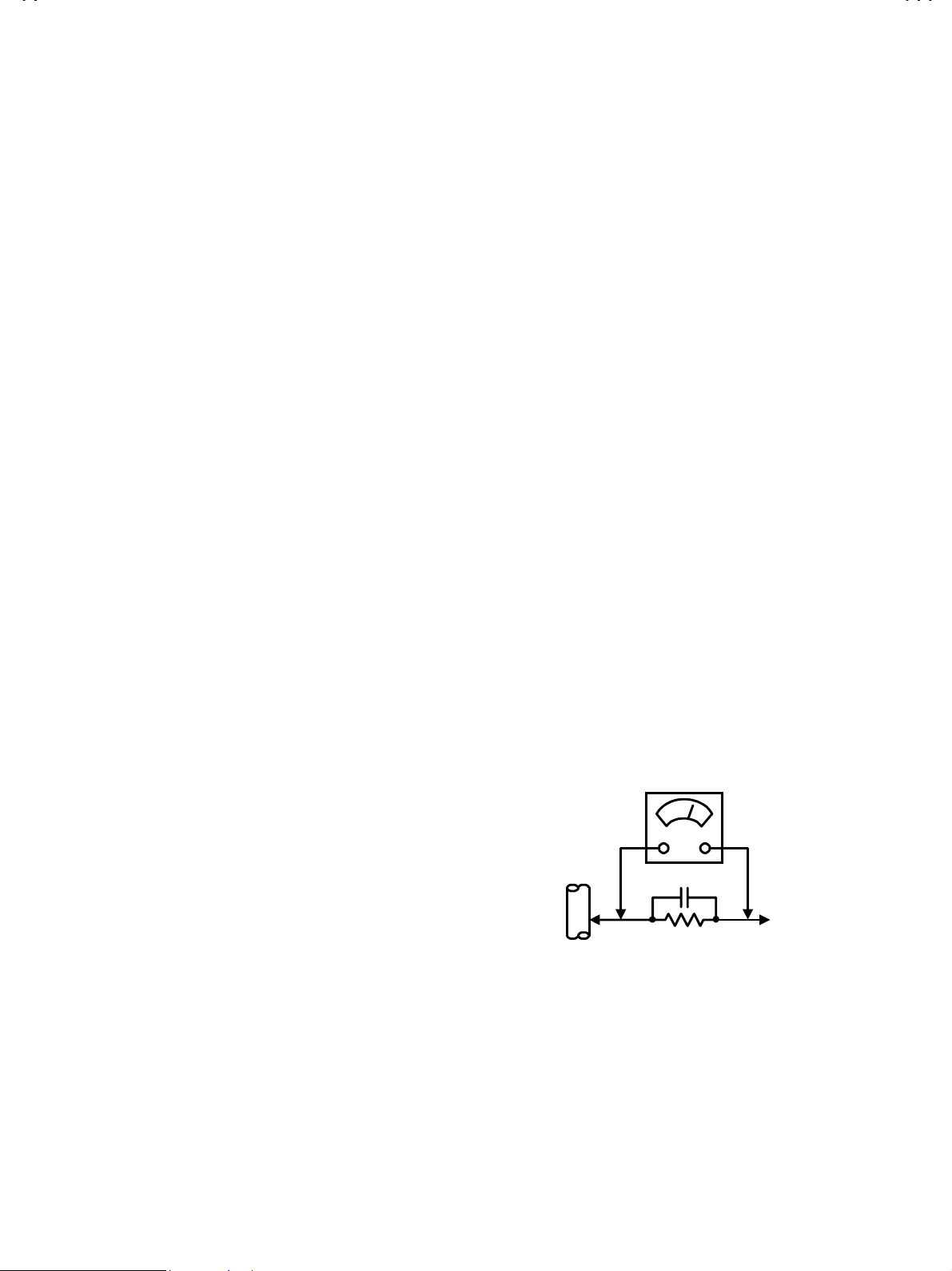
Alternate Check Method
""""
Plug the AC lin e c or d dir ec tly into t h e AC ou tlet (do not use a line
isolati on transform er during t his check.). Use an AC voltmet er
having 1000 ohms per volt or more sensitivity in the following
manner. Connect a 1 500! 10W resistor paralleled by a 0.15#F
AC-typ e capacitor betw een an expos ed metal part and a known
good earth ground (water pipe, etc.). Measure the AC voltage
across the resistor with the AC voltmeter. Move the resistor
connect ion t o each exp os ed met al p art, p articul arl y any exp osed
metal part h avin g a return p ath to th e chassis , and meas ure th e
AC voltag e across the res istor. N ow, re vers e the plug in the AC
outlet and repeat each measurement. Any voltage measured
must not exceed 0.75V AC (r.m.s.). This corresponds to 0.5mA
AC (r.m.s.).
However , i n t ropic al area, this m us t not e xc eed 0.3V AC (r . m.s . ).
This corresponds to 0.2mA AC (r.m.s.).
0.15μF AC-TYPE
1500
GOOD EARTH GROUND
!
AC VOLTMETER
(HAVING 1000
OR MORE SENSITIVITY)
10W
!
/V,
PLACE THIS PROBE
ON EACH EXPOSED
METAL PART
No.51731
3
Page 4

A
V-29M201
FEATURES
N ew ch assi s des ig n enabl es us e of a main b oard wi th s imp lif ied
"
circuitry.
Provided with miniature tuner (TV/CATV).
"
PLL synthesizer system TV/CATV totaling 180 channels.
"
Multifunctional remote control permits picture adjustment.
"
With AUDIO. VIDEO INPUT terminal.
"
Variable audio output terminal.
"
Adoption of the VIDEO STATUS function.
"
Adoption of the ON/OFF TIMER function.
"
With 75ΩV/U in common (F-Type) ANT Terminal.
"
SLEEP TIMER for setting in real time.
"
Wide range voltage (90V~260V) AC power input.
"
4
No.51731
Page 5
A
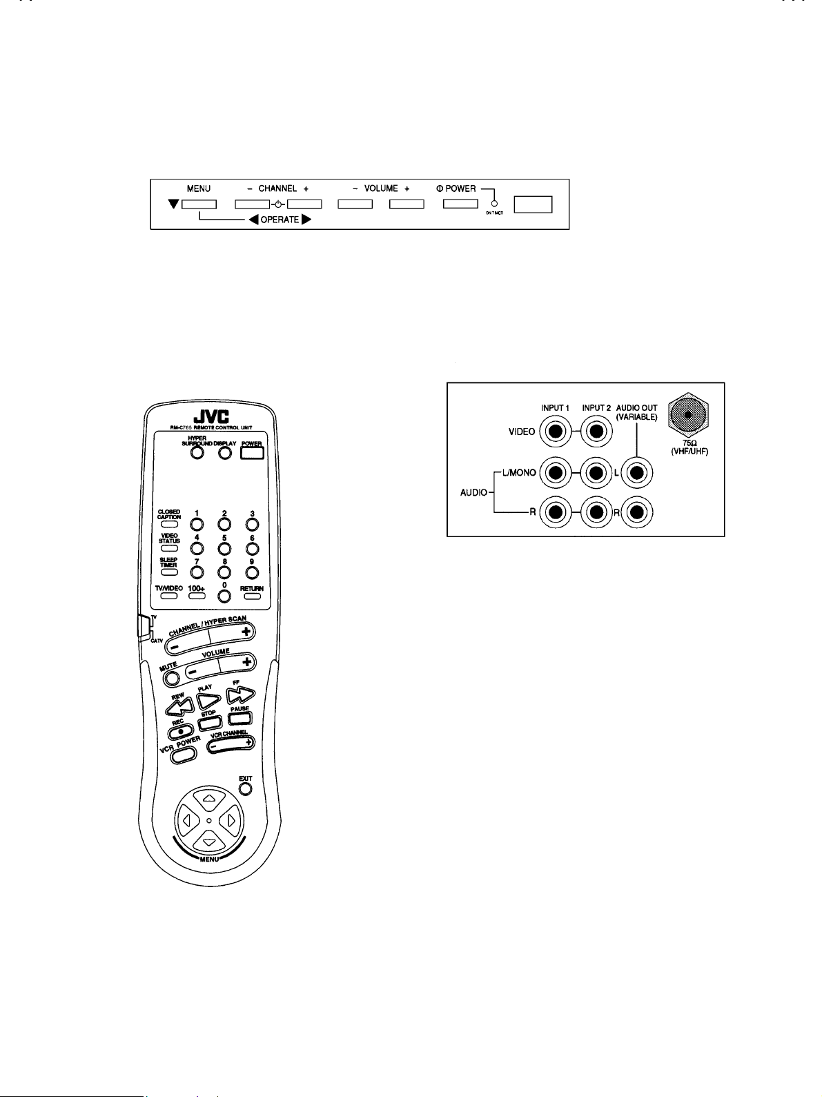
FUNCTIONS
■
FRONT CONTROL
V-29M201
■
REMOTE CONTROL UNIT
(RM-C765-1A)
■■■■
REAR VIEW
No.51731
5
Page 6

A
V-29M201
SPECIFIC SERVICE INSTRUCTIONS
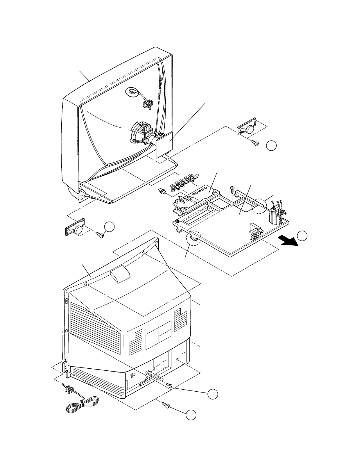
DISASSEMBLY PROCEDURE
REMOVING THE REAR COVER
1. Unplug the power supply co rd.
2. R emove th e 7 s cr ews m ark ed
shown in Fig.1.
When rei nstalling t he rear cover , carefully push it inward after
*
*
**
inserting the chassis into the rear cover groove.
and 2 scr ews m ark ed
AAAA
REMOVING THE CHASSIS
After removing the rear co ver.
%%%%
1. Sli ghtly r aise th e both s ides of the ch assis b y han d and r emov e
the 2 claws under the both sides of the chassis from the front
cabinet.
2. Dr aw the chassis backwar d along the rail i n the arr ow direc tion
marked
(If necessary, take off the wire clamp , connectors etc.)
as shown in the Fig.1.
CCCC
BBBB
as
When conducting a check with power supplied, be sure to
*
*
**
confirm that the CRT earth wire is connected to the CRT
SOCKET PWB and the MAIN PWB.
REMOVING THE SPEAKER
After removing the rear cover and chassis.
%%%%
1. Remove the 2 screws marked
2. Follow the same steps when removing the other hand speaker.
as shown in Fig.1.
DDDD
CHECKING THE MAIN PW BOARD
1. To check the back sid e of th e MA IN PW Board.
1) Pull out the chassis. (Refer to REMOVING THE CHASSIS).
2) Erect th e chass is ver tic ally s o that you c an eas il y check t he
back side of the MAIN PW Board.
[CAUTION]
When erect ing the chassis, be c areful so th at there will b e no
%%%%
contacting with other PWB.
Befor e turning on pow er, m ake sur e th at th e CRT ear th wir e and
%%%%
other connectors are properly connected.
WIRE CLAMPING AND CABLE TYING
1. Be sure clamp the wire.
2. Never remove the cable tie used for tying the wires together.
Should it be inadvertently removed, be sure to tie the wires with a
new cable tie.
6
No. 51731
Page 7
A
FRONT CABI.
V-29M201
CRT SOCKET PWB
(Wit hin MAIN PW B)
D
FRONT
CONTROL PWB
REAR
COVER
MAIN PWB
CLAW
D
C
CLAW
(×2)
B
(×7)
A
No. 51731
7
Page 8
A
V-29M201
(CW)
MEMORY I C REPLAC EMENT
1. Memory IC
This model use a memory IC.
The memor y IC st or es dat a for proper op eration of vi d eo an d deflection c ir c ui ts .
When replacing, be sure to use an IC containing this (initial value) data.
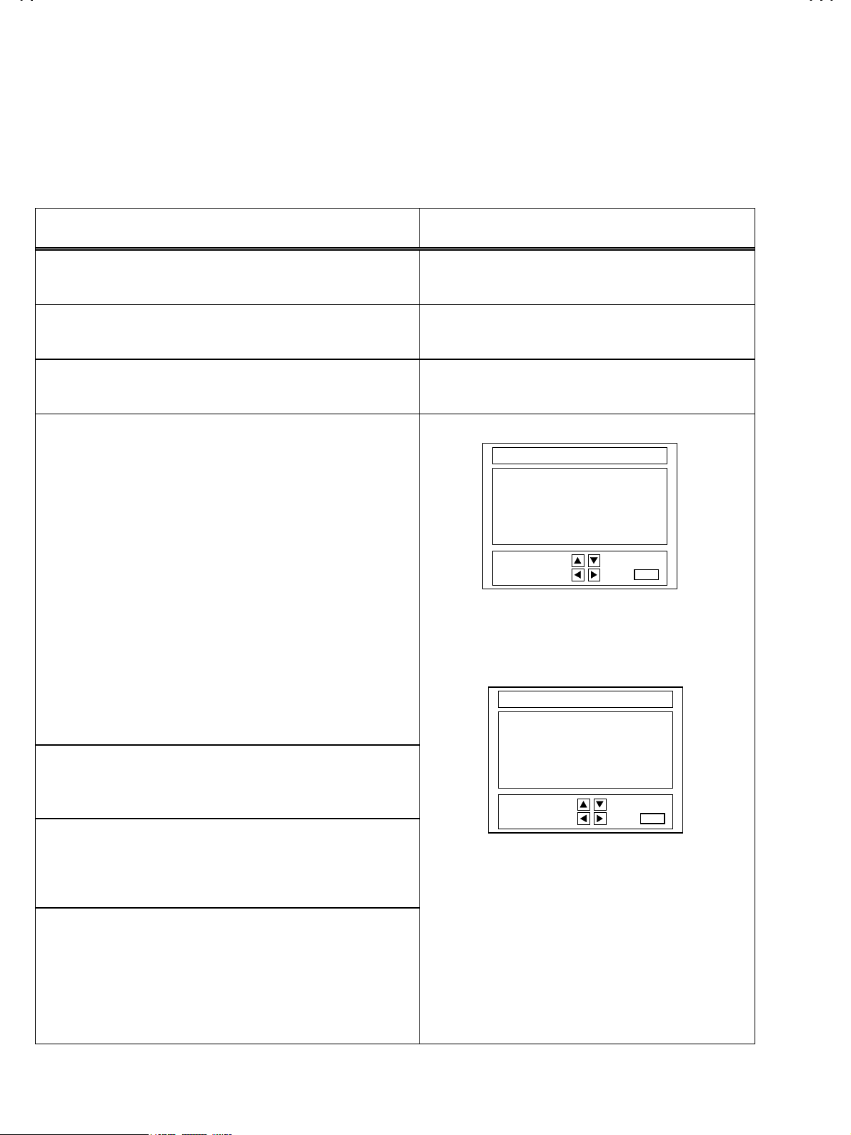
2. Memory IC repl acement procedure
PROCEDURE SCREEN DISPLAY
(1) Power off
Switch off the power and dis connec t th e pow er c or d from the out l et.
(2) Replace the me mor y IC
.
Be sure to u se memo ry ICs written with the i nitial data values.
(3) Power on
Connect the power cord to the outlet and switch on the power.
(4) System const ant chec k and set ting
It must not adjust with ou t sign al.
%%%%
1) Si mult aneousl y press the D ISPLA Y key and VI DEO S TAT US k ey
of the remote control unit.
2) The SERVICE MENU screen of Fig.1 is displayed.
3) While the SERVICE MENU is displayed, again simultaneously
press t h e D IS PLAY an d VIDEO STATU S keys to dis pl a y the Fi g.2
SYSTEM CONSTANT screen.
4) Refer to the SYSTEM CONSTANT table and check the setting
items. W here th ese diff er, sel ect the s etting item wit h the M ENU
UP / DOW N key an d adjust the setting with the ME NU LEFT /
RIGHT keys. (The letters of the selected item are displayed in
yellow.)
5) Af ter adjus ting, release t he MEN U LEFT / RIG HT k ey to store t he
setting value.
6) Press the EXIT key twice to return the normal screen.
(5)
Receive chann el settin g
Refer to the OPERATING INSTRUCTIONS (USER’S GUID E) and
set the receive channel s (Channels Prese t) as described.
(6)
User setti n gs
Check the user setting items according to Table 2.
Where these do not agree, refer to the OPERATING
INSTRUCTIONS (USER’S GUIDE) and set the items as described.
SERVICE MENU
PICTURE SOUND
VIDEO STAT US OTHERS
LOW LIGHT HIGH LIGHT
RF AFC CHK VCO
I2C BUS CTRL
SELECT BY
OPERATE BY
Fig.1
SYSTEM CO NST ANT
GAME : YES
HYPER SCAN : YES
SURROUND : YES
CCD : YES
VIDEO : 2
SELECT BY
OPERATE BY
Fig.2
EXIT BY
EXIT
EXIT BY
EXIT
IT
IT
(7)
SERVICE MENU setting
Verify what to set in the SERVICE MENU, and set whatever is
necessary. (Fig.1) refer to the SERVICE ADJUSTMENT for setting.
8
No. 51731
Page 9
A
V-29M201
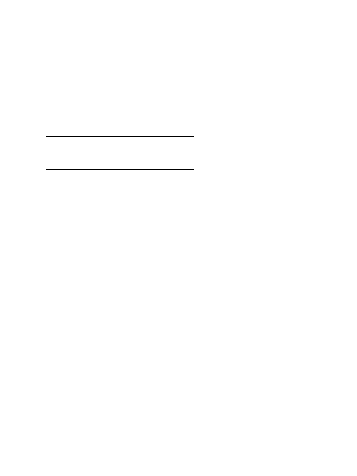
TABLE 1
TABLE 2
1. Setting of FUNCTION
2. Settin g of ME NU
( System Constant Setting )
Setting item Setting content Setting value
GAME YES
HYPER SCAN YES
SURROUND YES
CCD YES
VIDEO 2
(User settin g val ue)
Setting item Setting value
MAIN POWER OFF
SUB POWER ON
CHANNEL CH 02
CHANNEL PRESET Refer to OPERATING INSTRUCTIONS
VOLUME 10
TV/VIDEO TV
DISPLAY OFF
SLEEP TIMER 0
VIDEO STATUS STANDARD
CLOSED CAPTION OFF (CC1/T1)
HYPER SURROUND OFF
TINT CENTER
COLOR CENTER
PICTURE CENTER
BRIGHT CENTER
DETAIL CENTER
BASS CENTER
TREBLE CENTER
BALANCE CENTER
MTS STEREO
TV SPEAKER ON
SET CLOCK Unnecessary to set
ON/OFF TIMER NO
CHANNEL SUMMARY Unnecessary to set
SET LOCK CODE Unnecessary to set
AUTO TUNER SETUP Unnecessary to set
TUNER MODE AIR
NOISE MUTING OFF
CLOSED CAPTION OFF (CAPTION : CC1 TEXT : T1)
LANGUAGE ENG.
YES NO
YES NO
YES NO
YES NO
210
No. 51731
9
Page 10
A
V-29M201
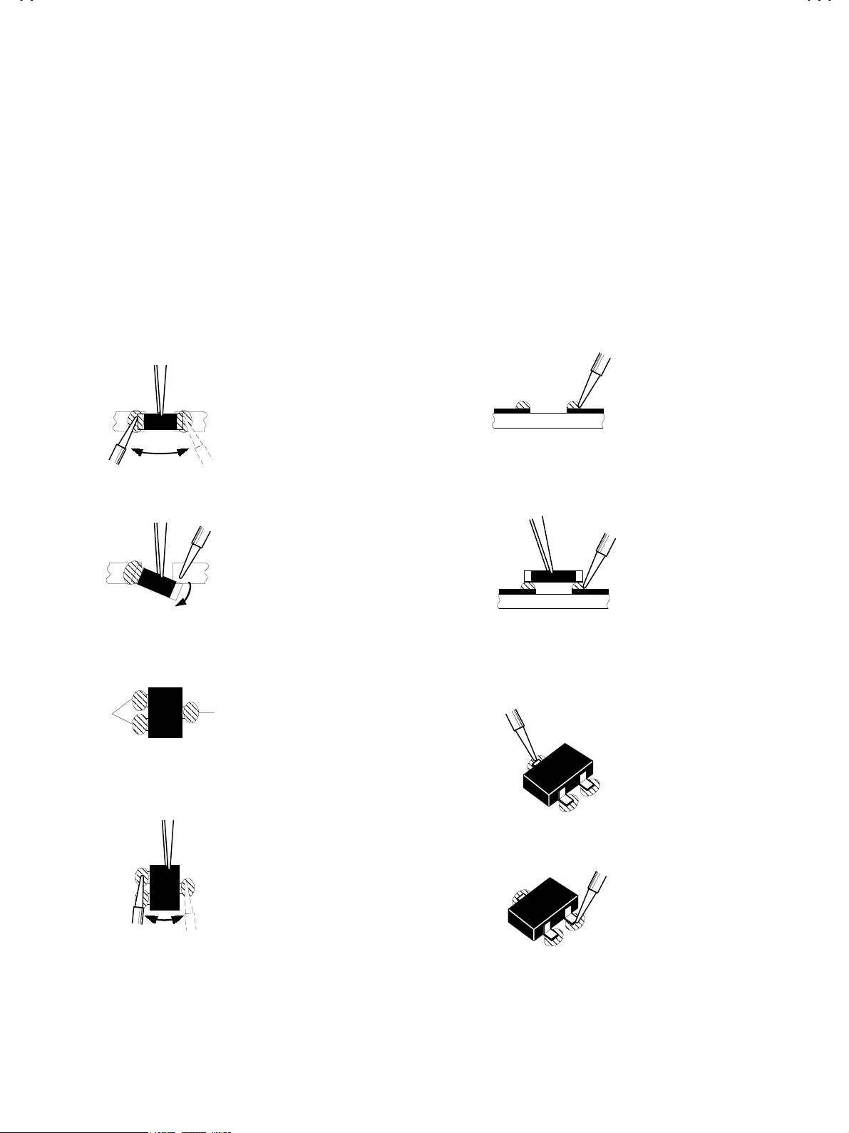
REPLACEMENT OF CHIP COMPONENT
CAUTIONS
!
1. Avoid heating for more than 3 seconds.
2. Do not rub the electrodes and the resist parts of the pattern.
3. When removing a chip part, melt the solder adequately.
4. Do not reus e a chip p ar t after removi ng it.
SOLDERING IRON
!
1. Use a high insul ati on solder in g iron with a thi n p oint ed end of it.
2. A 30w soldering iron is recommended for easily removing parts.
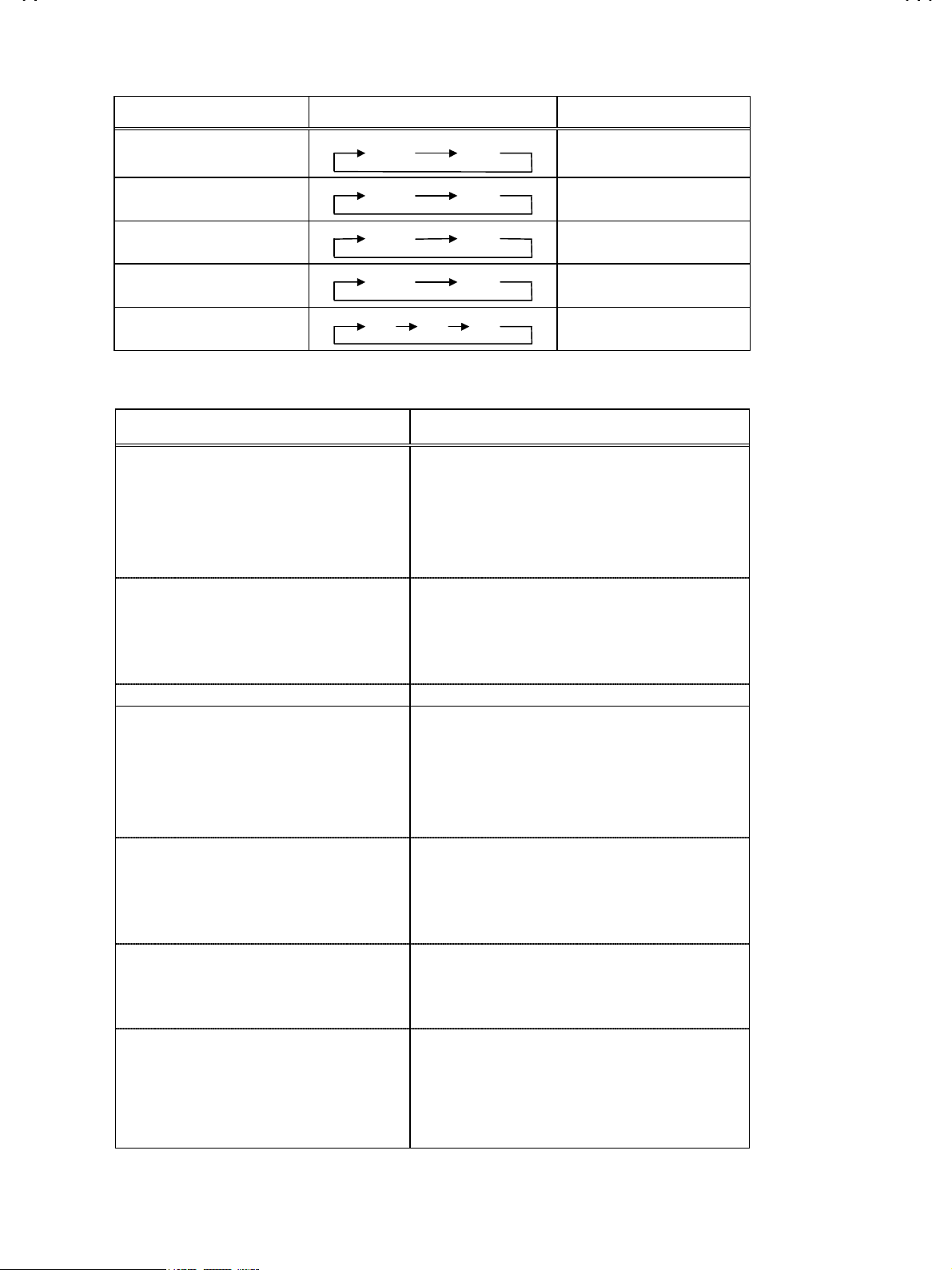
REPLACEMEN T STEPS
!
How to remove Chip parts
1.
Resistors, capacitors, etc
####
(1) As shown in the figure, push the part with tweezers and
alternately m elt th e s older at each en d.
(2) S hif t wi th tweezers an d r em o ve the chip par t.
Transistors, diodes, variable resistors, etc
####
(1) Apply extra solder to each lead.
SOLDER
SOLDER
2. How to install Chip par ts
Resistors, capacitors, etc
####
(1) Apply solder to the pattern as indicated in the figure.
(2) Grasp th e chip part with tw eezers and pl ace it on th e sold er.
Then heat an d m elt t h e s old er at b oth en ds of th e chip part .
Transistors, diodes, variable resistors, etc
####
(1) Apply solder to the pattern as indicated in the figure.
(2) Grasp the chip part with tweezers and place it on the solder.
(3) First solder lead
as indicated in the figure.
A
A
(2) As shown in the figure, push the part with tweezers and
alternat el y melt t he s old er at each lead . Shif t and r emov e th e
chip part.
Note : After removing the part, remove remaining solder from the
pattern.
10
No.51731
(4) Then solder leads
A
and C.
B
C
C
B
B
Page 11
A
V-29M201
SERVICE ADJUSTMENTS
ADJUSTMENT PREPARATION:
1. You can ma ke the n eces sary adjust me nts f or t his unit with eith er th e r emot e cont ro l unit or with the adj ustme nt equ ipmen t a nd
part s as given below.
2. Adjustm en t with th e remote con trol un it i s m ade on t h e ba sis of t h e initial settin g v al u es , howev er, the new set ti n g values which
set the screen to its optimum condition may differ from the initial settings.
3. Make sure that AC power is turned on correctly.
4. Turn on the power for the set and test equipment before use, and start the adjustment procedures after waiting at least 30 minutes.
5. Unless otherwise specified, prepare the most suitable reception or input signal for adjustment.
6. Never touch any adjustment parts which are not specified in the list for this adjustment-variable resistors, transformers, cond ensers, etc .
7. Presett i ng b ef or e ad jus tment.
Unless otherwise specified in the adjustment instructions, preset the following functions with the remote control unit.
VIDEO STATUS NORMAL
TINT, COLOR, PICTURE, BRIGHT,
DETAIL
BASS, TREBLE, BALANCE CENTER
HYPER SURROUND OFF
CENTER
ADJUSTMENT EQUIPMENT
1. DC voltm et er (or digit al voltmet er )
2. Oscilloscope
3. Signal generator ( Pattern genera tor ) [NTSC] [PAL -M] [PAL-N]
4. Remote control unit
5. TV audio multiplex signal generator
6. Frequency counter
ADJUSTMENT ITEMS
Check of B1 POWER SUPPLY
%
IF VCO adjustment
%
RF AGC adjustment
%
FOCUS adj us tment
%
DEFLECT IO N ad jus t m ent
%
V. HEIGHT, V. POSITION, V. LIN., V S CR adjustment
H. POSITION adjustment
VIDEO / CHROMA adjustment
%
WHITE BALANCE ( Low light ) adjustment
WHITE BALANCE ( High light ) adjustment
SUB BRIGHT adjustment
SUB CONTRAST adjustment
SUB COLOR adjustment
SUB TINT adjustment
MTS circuit adjustment
%
INPUT LEVEL check
STEREO VCO adjustment
SAP VCO adjustment
FILTER check
SEPARATION adjust ment
No. 51731
11
Page 12

A
V-29M201
(
)
(
)
(
)
(
)
(
)
(
)
)
(
)
(
)
(
)
ADJUSTMENT LOCATI ONS
F901
IC702
MEMORY
IC701
CPU
FRONT
MAIN PWB ASS'Y(1/2)
SOLDER SIDE
TOP
MPX
5
IC201
1
IC651
AV JAC K
TUNER
T111
IC101
C
CW
TP-E
U
13
B1
TP-91
Q522
HV
T522
HVT
B1
UPPER : FOCUS
LOWER : SCREEN
FRONT
D702
TP-R
T
U
P-E(
T
CRT SOCKET
PWB ASS'Y(2/2)
E1
CRT EARTH
BRAID ED ASS' Y
With in MAIN PWB ASS'Y
12
IC701
POWER/
ON TIME R
LED
S901
POWER SW
FRONT CONTROL PWB ASS'Y
No. 51731
VOL
VOL
+
+
+
+
CH
―
―
―
―
CH
+
+
+
+
OPERATE
SUB POWER
MENU
―
―
―
―
Page 13

A
BASIC OPERATION OF SERVICE MENU
1. TOOL OF SERVICE MENU OPERATIO N
Operate the SERVICE MENU with the REMOTE CONTROL UNIT.
2. SERVICE MENU ITEMS
In general, basic setting( adjust m ents ) items or verific ati ons are perfor m ed in the SERVIC E ME NU .
(1) PICTURE
(2) SOUND
(3) VIDEO STATUS
(4) OTHERS
(5) LOW LIGHT
(6) HIGH LIGHT
(7) RF A F C CHK
(8) VCO (CW)
2
(9) I
C BUS CTRL
・・・・・・・・・・・・・・・・・・
・・・・・・・・・・・・・・・・・・・・
・・・・・・・・・・・・・
・・・・・・・・・・・・・・・・・・・
・・・・・・・・・・・・・・・・
・・・・・・・・・・・・・・・・
・・・・・・・・・・・・・・・
・・・・・・・・・・・・・・・・・
・・・・・・・・・・・・・・
3. Basic Oper a t io ns o f t he SE RV ICE MEN U
(1) How to enter the SERVICE MENU.
Press t h e DISPL A Y k ey an d VIDEO STATU S k e y of th e remot e control un it at t he same tim e t o en ter the SERVI C E MEN U s c reen
shown in figure page la ter.
This sets the setting values (adjustment values) of the VIDEO/CHROMA and DEFLECTION circuits.
This sets the setting values (adjustment values) of the AUDIO circuit.
This is used when the THEATER and GAME MODE is adjusted.
This is used when the OTHERS MODE is adjusted.
This sets the setting values (adjustment values) of the WHITE BALANCE circuit.
This sets the setting values (adjustment values) of the WHITE BALANCE circuit.
This is used when the IF VCO is adjusted.
[Do not adjust]
This is used when the IF VCO is adjusted.
This is used when ON/OFF of the I2C BUS CTRL is set.
[Fixed ON]
V-29M201
①
(2) SERVICE MENU screen selection
Press the UP / DOWN key of the MENU to select any of the following items.
(The lett ers of t h e sel ec t ed it ems are disp l ayed in yellow .)
PICTURE
●
VIDEO STATUS
●
LOW LIGHT
●
RF AFC CHK
●
I2C BUS CTRL
●
SOUND
●
OTHERS
●
HIGH LIGHT
●
VCO (CW)
●
(3) Ente r the any setting ( adjustment ) mode
PICTURE, SOUND and OTHERS mode
"
1) If select any of PICTURE, SOUND or OTHERS items, and the LEFT / RIGHT key is pressed from SERVICE MENU ( MAIN
MENU ), the screen ② will be dis p layed as sh ow n in fi gure pag e later.
2) T hen the U P / DOWN key is press ed, th e PIC TU RE mod e scr een ③ or th e SOUND m ode s cr een ④ or the OTHERS mode
screen ⑤ is displayed, and the PICTURE, SOUND or OTHERS setting can be performed.
VIDEO STATUS, LOW LIGHT, HIGH LIGHT, RF AFC CHK, VCO (CW) and I
"
1) If select any of VIDEO STATUS / LOW LIGHT / HIGH LIGHT / RF AFC CHK / VCO (CW) / I
2
C BUS CTRL mode
2
C BUS CTRL items, and the LEFT
/ RIGHT k ey is pr essed f r om SER V I CE MEN U ( MAIN MEN U ), the scr eens ⑥ ⑦ ⑧ ⑨ ⑩ ⑪ will be disp lay ed as shown in
figure page later.
2) Then the settin gs or verific ati ons c an b e performed.
No. 51731
13
Page 14

A
V-29M201
①①①①
SERVICE MENU (MAIN MENU)
SERVICE MENU
PICTURE SOUND
VIDEO STATUS OTHERS
LOW LIGHT HIGH LIGHT
RF AFC CHK VCO (CW)
I2C BUS CTRL
SELECT BY
OPERATE BY
⑧⑧⑧⑧
HIGH LIGHT MODE
HIGH LIGHT
***
***
******
⑨⑨⑨⑨
RF AFC CHK MODE [DO NOT ADJUST]
EXIT BY
***
***
******
EXIT BY
EXIT
EXIT
②②②②
SCREEN
IT
IT
SELECT BY
1. NOISE
STATUS
SELECT BY
OPERATE BY
④④④④
SOUND MODE
EXIT BY
EXIT
********
********
****************
EXIT BY
EXIT
***
***
******
IT
IT
③③③③
1. PICTURE
**** ****
**** ****
**** ******** ****
SELECT BY
OPERATE BY
⑤⑤⑤⑤
1.OSD POS.
**** ****
**** ****
**** ******** ****
SELECT BY
OPERATE BY
PICTURE MODE
OTHERS MODE
***
***
******
****
****
********
EXIT BY
EXIT
***
***
******
****
****
********
EXIT BY
EXIT
IT
IT
RF AFC
FINE
STATUS
SELECT BY
OPERATE BY
⑩⑩⑩⑩
VOC (CW) MODE
VCO (CW)
TOO HIGH
ABOVE REFERENCE
BELOW REFERENCE
TOO LOW
SYNC : YES
⑪⑪⑪⑪
I2C BUS CTRL MODE
[FIXED ON]
I2C BUS ON
OPERATE BY
***
***
******
********
********
****************
********
********
****************
EXIT BY
EXIT
EXIT BY
EXIT
EXIT BY
EXIT
ON
IT
⑥⑥⑥⑥
VIDEO STATUS MODE
THEATER
TINT G DRI V E
COLOR B DRI V E
PICTURE R CUT.
BRIGHT G CUT.
DETAIL B CUT.
IT
IT
SELECT BY
OPERATE BY
BRIGHT
BRIGHT
***
***
******
***
***
******
***
***
******
***
***
******
***
***
******
⑦⑦⑦⑦
LOW LIGHT MODE
***
***
******
*** *** ***
*** *** ***
*** *** ****** *** ***
***
***
******
***
***
******
***
***
******
***
***
******
***
***
******
EXIT BY
EXIT
EXIT BY
EXIT
Press
VIDEO
STATUS
IT
IT
Key
TINT G DRI V E
COLOR B DRI V E
PICTURE R CUT.
BRIGHT G CUT.
DETAIL B CUT.
SELECT BY
OPERATE BY
***
***
******
***
***
******
***
***
******
***
***
******
***
***
******
GAME
***
***
******
***
***
******
***
***
******
***
***
******
***
***
******
EXIT BY
EXIT
IT
14
No. 51731
Page 15

A
(4) Setting method
1) UP / DOWN key of the MENU
Select the SETTING ITEM.
2) LEFT / RIGHT key of the MENU
Setting(adjust) the SETTING VALUE of the SETTING ITEM.
When the key is released the SETTING VALUE will be stored
(memorized).
3) EXIT key
Returns to the previous screen.
[NOTE] (PICTURE MODE ONLY)
When the INT IAL SET TING VA LUE is tur ned to yel low, y ou can ad just
the values but you cannot adjust the values when it is turned to red
(because the sign al c on ditions, etc . ar e n ot m et.)
(5) Releasing SERVICE MENU
1) After returni ng to the SERVICE MENU upon c ompletion of t he setting
(adjust m ent ) w or k, pr ess the EXIT k ey ag ai n.
The s ettings f or LOW LIGHT and H IGH LIGHT are descr ibed in t he W HITE
★
BALANCE page of ADJUSTMENT.
1. PICTURE
**** ****
**** ****
**** ******** ****
SELECT BY
OPERATE BY
PICTURE MODE
SETTING
ITEM
1. NOISE
STATUS
SELECT BY
OPERATE BY
SOUND MODE
***
***
******
****
****
********
EXIT BY
IT
EXIT
INITIAL
SETTING VALUE
↓ (Adjust)
SETTING VALUE
***
***
******
****
****
********
EXIT BY
IT
EXIT
V-29M201
The setting for VCO(CW) are described in the IF VCO page of ADJUSTMENT.
★
THEATER
The letter of the selected
Items are displayed in yellow.
TINT G DRIVE
COLOR B DRIVE
PICTURE R CUT.
BRIGHT G CUT.
DETAIL B CUT.
SELECT BY
OPERATE BY
***
***
******
***
***
******
***
***
******
***
***
******
***
***
******
***
***
******
***
***
******
***
***
******
***
***
******
***
***
******
EXIT BY
EXIT
1. OSD POS.
**** ****
**** ****
**** ******** ****
SELECT BY
OPERATE BY
OTHERS MODE
TINT G DRIVE
COLOR B DRIVE
PICTURE R CUT.
BRIGHT G CUT.
DETAIL B CUT.
SELECT BY
OPERATE BY
IT
Press
VIDEO
STATUS
Key
VIDEO STATUS MODE
***
***
******
***
***
******
***
***
******
***
***
******
***
***
******
GAME
***
***
******
****
****
********
EXIT BY
EXIT
***
***
******
***
***
******
***
***
******
***
***
******
***
***
******
EXIT BY
EXIT
IT
IT
No. 51731
15
Page 16

A
V-29M201
INITIAL SETTING VALUE OF SERVICE MENU
1. Adjustment of the SERVICE MENU is made on the basis of the initial setting values ; however, the new setting values which set
the screen in its optimum condition may differ from the initial setting.
2. Do not change the initial Setting Values of the Setting (Adjustment) items not listed In “ADJUSTMENT”.
PICTURE MODE
"
The four setting items in the video mode No.8 EXT PIC., No.9 EXT BRI., No.10 EXT COL., and No.11 EXIT TINT are linked to the items in
$
the TV MODE N o.1 PICT URE, N o.2 BRIG HT, N o. 5 COL.N TSC and N o.6 TINT , res pectiv ely. When the s etting items in th e TV mode are
adjust ed, th e val u es in th e s etting i t ems i n t h e vid eo m ode ar e revised au t om at ically t o the sa m e v alu es i n the T V m ode.(Th e initial setting
values given in ( ) are off-set values.)
When the f our items (No.8, 9, 10 and 11) are adjus t ed in t h e vid eo mode, th e s etti ng v alues in each it em ar e re vised ind ep endently.
$
No. Setting (Adjustment) item Variable range Initial setting value
1. PICTURE
2. BRIGHT 0~127 64
3. COL. PALM 0~127 80
4. COL. PALN 0~127 80
5. COL. NTSC 0~127 95
6. TINT
7. TV DTL 0~63 33
8. EXT PIC.
9. EXT BRI.
10. EXT COL.
11. EXT TINT
12. EXT DTL 0~63 30
13. P/N KILL 0 / 1 0
14. Y S CONT 0~31 31
15. TV Y-DL 0~41
16. EXT Y-DL
17. WPL SW 0 / 1 0
18. Y GAMMA 0 / 1 0
19. P/N G P. 0 / 1 0
20. COL. L SW 0 / 1 1
21. COL. LMT.
22. PN C. ATT 0~31
23. OFST. SW 0 / 1 0
24. OFST. B-Y 0~15 8
25. OFST. R-Y 0~15 8
26. C-TOF SW 0 / 1 1
27. TV T FO 0~31
28. TV T Q 0~30
29. EXT T FO 0~30
30. EXT T Q 0~30
31. C-TRAP 0 / 1 0
32. C-TR. FO 0~32
33. C-TRAP Q 0~31
34. FIX B/W 0 / 1 0
35. APA P. FO 0~32
36. DC TRAN.
37. B. ST. SW 0 / 1 0
38. B. ST. PO. 0~70
39. ABL GAIN 0~74
40. ABL PO. 0~70
41. HALF T.
42. DRV G SW 0 / 1 0
43. NT. COMB 0 / 1 1
44. COIN DE T
45. NOISE L.
46. VCD MODE 0 / 1 0
47. V AGC SP 0 / 1 0
48. H POS. 50
49. H BLK. 50
50. V POS. 50
0~127
0~127
25 (0)
±
25 (0)
±
25 (+4)
±
25
±
0~4
0~3
0~7
0~2
0~3
0~3
0~31
0~7
0~7
60
65
(+3)
1
1
4
1
3
3
6
0
2
16
No. 51731
Page 17

A
PICTURE MODE
"
No. Setting (Adjustment) item Variable range Initial setting value
51. V SIZE50 0~127 71
52. V S CR50 0~127 83
53. V LIN. 50 0~31 4
54. H POS. 60 0~31 10
55. H BLK. 60 0~70
56. V POS. 60 0~70
57. V SIZE60 0~127 72
58. V S CR60 0~127 99
59. V LIN. 60 0~31 3
60. RF AGC 0~255 160
SOUND MODE
"
No. Setting (Adjustment) item Variable range Initial setting value
1. NOISE 0 / 1 1
2. IN LEVEL 0~63 50
3. FH MON. 0 / 1 0
4. ST VCO 0~63 25
5. PILOT 0 / 1 0
6. FILTER 0~63 30
7. LOW SEP. 0~63 22
8. HI SEP. 0~63 23
9. 5FH MON. 0 / 1 0
10. SAP VCO 0~63 26
11. IN GAIN 0 / 1 0
12. FIL. OFF. 0~10 0
V-29M201
VIDEO STATUS MODE
"
Setting (Adjustment) item Variable range
TINT
COLOR
PICTURE -30~+20 -10 -10
BRIGHT
DETAIL
G DRIVE -99~+50 -22 0
B DRIVE -99~+50 -54 0
R CUT.
G CUT.
B CUT.
Initial settin g val ue
THEATER GAME
20 0 0
±
20 -3 -3
±
20 0 0
±
15 0 -5
±
10 0 0
±
10 0 0
±
10 0 0
±
No. 51731
17
Page 18

A
V-29M201
A
OTHERS MODE
"
No. Setting (Adjustment) item Variable range Initial setting value
1. OSD POS. 0~31 7
2. LOCK DET 0 / 1 0
3. SD SEL. 0~20
4. H-CK SW 0 / 1 0
LOW LIGHT MODE
"
Setting (Adjustment) item Variable range Initial setting value
R CUTOFF 0~255 20
G CUTOFF 0~255 20
B CUTOFF 0~255 20
HIGH LIGHT MODE
"
Setting (Adjustment) item Variable range Initial setting value
G DRIVE 0~255 128
B DRIVE 0~255 128
RF AFC CHK MODE
"
Setting (Adjustment) item Variable range Initial setting value
RF AFC ON / OFF ON
FINE -77~+77
2
I
C BUS CTRL MODE
"
Setting (Adjustment) item Variable range Initial setting value
I2C BUS ON / OFF
±××
[Fixed ON]
DO NOT
DJUST
18
No. 51731
Page 19

A
■■■■
)
ADJUSTMENTS
B1 POWER SUPPLY
Item
Check of
B1 POWER
SUPPLY
Measuring
instrument
DC Vol tme t e r
ADJU STMENT O F IF VCO
Item
IF VCO
adjustment
Measuring
instrument
Signal
generator
VCO (CW
TOO HIGH
ABOVE REFERENCE
BELOW REFERE NCE
TOO LOW
SYNC : YES
Test point Adjustment ite m Description
B1 ( B1
1
(TP-91)
TP-E(#)
( B1
3
Test point Adjustment ite m Description
Connector
pin)
Connector
pin)
CW TRANSF. (T111)
[VCO (CW)] mode
YELLOW
1. Receive a blac k an d w hi te sign al (c olor off ) . (NT S C)
2. Connect the DC voltmeter to B1
91) and TP-E(#) (B1 connector 3
3. Confirm that the voltage is DC129.5V V.
Under normal conditions, no adjustment is required. and it
%
must not ad jus t w it hout sign al.
1. Receive a NTSC broadcast. (use channels without offset
frequency).
2. Select the VCO(CW) mode from the SERVICE MENU.
3. Confirm the color change (yellow) from “TOO HIGH” to
TOO LOW”by CW TRAN SF. and “SYNC : YES” being
“
shown on the screen. Then, adjust CW TRANSF. until
BELOW REFERENCE” mark turns yellow and confirm
“
again “ SYNC : YES” being shown on the screen.
V-29M201
connector 1 pin (TP-
pin).
+2
-2.5
ADJU STMENT O F RF AGC
RF AGC
adjustment
ADJU STMENT O F FOCUS
FOCUS
adjustment
Signal
generator
EXIT BY
EXIT
IT
No.60 RF AGC
FOCUS VR
[In HVT]
1. Receive a broadcast.
2. Select “No.60 RF AGC” of the PICTURE mode in SERVICE
MENU.
3. Press the MUTING key and turn off color.
4. W ith the M ENU L EFT k ey, g et nois e in t he scr een pic ture. ( 0
side of sett in g value)
5. Press the MENU R IGHT k ey and s top wh en n ois e dis app ears
from the screen.
6. Change to other channels and make sure that there is no
irregularity.
7. Press the MUTING key and get color out.
1. Receive a crosshatch signal.
2. While looking at the screen, adjust FOCUS VR so that the
vertic al and hor i z ont al lines will be cl ear and in fin e det ail.
3. Make sure t hat the pictur e is in focus even when the sc reen
gets dark en ed.
No. 51731
19
Page 20

A
V-29M201
(
)
(
)
(
)
ADJUSTMENT OF DEFLECTION CIRCUIT
Item
V. HEI GHT ,
V. POSITION,
V. LIN.
V. S CR
adjustment
Screen
size
92%
Measuring
instrument
Signal
generator
Test point Adjustment ite m Description
No.56 V POS. 60
No.57 V SIZE 60
No.58 V S CR60
No.59 V. LIN. 60
No.50 V POS.50
No.51 V SIZE 50
No.52 V S CR50
No.53 V LIN.50
Scree s ize
Picture
size
100%
[60Hz]
1. Receive a crosshatch signal.(NTSC or PAL-M)
2. Confirm that the value of PICTURE MODE “No.56 V PO S.
60” is 0.
3. C onfirm th e initial setting value of t he “No.57 V SIZE 60”,
No.58 V S CR60” and “No.59 V LIN. 60”.
4. Adjust the vertical screen size to 92% with the PICTURE
MODE “No. 57 V SIZE 60”.
5. Adjust the PICTURE M ODE “No.59 L LIN. 60” and “No.58
V S CR60” to get the best vertical linearity.
NOTE :
1. The PICTURE MODE “No.56 V POS. 60” is fixed on value 0.
2. Bottom of screen is to be located within the 85%~95% range.
[50Hz]
1. Receive a crosshatch signal. (PAL-N)
2. Confirm the initial setting value of the “No.50 V POS.50”,
“No.51 V SIZE 50” , “No.52 V S CR 50” and “No.53 V LIN.50”.
3. Adjust the vertical screen size to 92% with the PICTURE
MODE “No.51 V SIZE50”.
4. Adjust the P ICT URE MO DE “ No. 53 V LIN. 50” and “N o.52 V S
CR50” to get the best vertical linearity.
5. Adjust the PICTURE MODE “No.50 V POS.50” so that the
vertic al cent er lin e com es clos e to th e CRT vertic al cent er as
much as possible.
Readjust V SIZE, V LIN., V S CR if necessary.
"
H. POSITION
adjustment
Signal
generator
Picture size
100%
No.54 H PO S .60
No.48 H PO S .50
NOTE :
1. Bottom of screen is to be located within the 85%~95% range.
[60Hz]
1. Receive a crosshatc h sig n al. ( NTSC or PAL- M)
2. Select the “No.54 H POS. 60” of the PICTURE mode in
SERVICE MENU.
3. Confirm the initial setting value of the "No.54 H POS. 60".
4. Adjust the “No.54 H POS. 60” until the screen will be
horizontally centered.
[50Hz]
1. Receive a crosshatch signal. (PAL-N)
2. Select the “No.48 H POS. 50” of the PICTURE mode in
SERVICE MENU.
3. Confirm the initial setting value of the "No.48 H POS. 50".
4. Adjust the “No.48 H POS. 50” until the screen will be
horizontally centered.
20
No. 51731
Page 21

A
ADJUSTMENT OF VIDEO / CHROMA CIRCUIT
Item
WHITE
BALANCE
(Low Light)
adjustment
Measuring
instrument
Signal
Generator
Remote
control unit
[LOW LIGHT] MOD E
R CUTOFF
BRIGHT
*** *** ***
*** *** ***
*** *** ****** *** ***
BRIGHT
REMOTE CONTROL UNIT
Test point Adjustment ite m Description
BRIGHT
R CUTOFF
G CUTOFF
B CUTOFF
SCREEN VR
G CUTOFF
***
***
******
B CUTOFF
EXIT BY
IT
EXIT
BRIGHT
V-29M201
1. Receive a bl ac k-and- w hit e si gnal.(Color off )
2. Select the【LOW LIGHT】MODE from the SERVICE MENU.
3. Set the initial s etting value of BRIGHT with th e LEFT / RIGH T
key of the remote control unit.
4. S et the initial s etting val ue of R CUT OFF, G CUT OFF and B
CUTOFF with the
5. Dis play a singl e horiz ontal line by p ressing t he
remote control unit.
6. Turn the screen VR all the way to the left.
7. Turn th e screen VR gradually t o the right f rom the left u ntil
either one of the red, blue or green colors appears faintly.
8. Adjust the two colors which did not appear until the single
horizontal line tha t is displayed becomes white using the
keys of the remote control unit.
⑨⑨⑨⑨
9. Turn the scr een VR to where the singl e horizontal lin e glows
faintly.
10. Press the
The
*
②②②②
EXIT key is the cancel key for the WHITE BALANCE.
③③③③
to
④④④④
key of the remote control unit.
⑨⑨⑨⑨
key to return to the regular screen.
key of the
①①①①
to
④④④④
WHITE
BALANCE
(High Light)
adjustment
H.LINE O N
1 2
R CUTOFF
4 5
R CUTOFF
7 8
H.LINE O FF
G CUTOFF
G CUTOFF
Signal
Generator
Remote
control unit
[HIGH LIGHT] MODE
G DRIVE
HIGH LIGHT
***
***
******
B DRIVE
EXIT
3
B CUTOFF
6
B CUTOFF
9
G DRIVE
B DRIV E
***
***
******
EXIT BY
IT
EXIT
1. Receive a blac k an d w hi te sign al (c olor off ) . (NT S C)
2. Select the HIGH LIGHT mode in the SERVICE MENU.
3. Confirm the initial setting value of “G DRIVE” and “B DRIVE”.
4. Adjust the screen color to white with the
⑤⑤⑤⑤, ⑥⑥⑥⑥, ⑧⑧⑧⑧
and
keys of the remote control unit.
Remote Control Unit
key : H.LINE ON
①
key : H.LINE OFF
②
key : EXIT
③
key : G DRIVE
⑤
key : B DRIVE
⑥
key : G DRIVE
⑧
key : B DRIVE
⑨
▲
▲
▼
▼
⑨⑨⑨⑨
No. 51731
21
Page 22

A
V-29M201
Item
SUB BR I GHT
adjustment
SUB
CONTRAST
adjustment
SUB COLOR
adjustment
Measuring
instrument
Remote
control unit
Remote
control unit
Remote
control unit No.3 COL. PA LM
Test point Adjustment ite m Description
No.2 BRIGHT
No.1 PICTURE
1. Receive a NT SC broadcast.
2. Select “No.2 BRIGHT” of the PICTURE mode in SERVICE
MENU.
3. Confirm the initial setting value of the “No.2 BRIGHT” .
4. If the brightness is not the best with the in itial settin g value,
make fin e adjustm ent of th e “No.2 BRIG HT” until you get th e
optimu m bri ghtness.
1. Receive a NT SC broadcast.
2. Select “No.1 PICTURE” of the PICTURE mode in SERVICE
MENU.
3. Confirm the initial setting value of the “No.1 PICTURE”.
4. If the contrast is not the best with the initial setting value, make
fine adjustment of the “No.1 PICTURE” until you get the
optimum contrast.
[PAL-M]
1. Receive a PAL -M br oadcast.
2. S elect “No.3 COL. PALM” of t he PICTURE mode in SERVICE
MENU.
3. Confirm the initial setting value of the “No.3 COL. PALM”.
4. If th e color is not th e best wit h the init ial setti ng value, make
fine adjustment until you get the best color.
SUB TINT
adjustment
Remote
control unit
No.4 C O L . P A LN
No.5 C O L . NTSC
No. 6 TINT
[PAL-N]
1. Receive a PAL -N bro adcast.
2. Select “No.4 C OL. PA LN” of the P ICT URE mod e in S ER VICE
MENU.
3. Confirm the initial setting value of the “No.4 COL. PALN”.
4. If th e color is not th e best wit h the init ial setti ng value, make
fine adjustment until you get the best color.
[NTSC]
1. Receive a NT SC broadcast.
2. Select “No.5 COL. NTSC” of the PICTURE mode in SERVICE
MENU.
3. Confirm the initial setting value of the “No.5 COL. NTSC”.
4. If th e color is not th e best wit h the init ial setti ng value, make
fine adjustment until you get the best color.
1. Receive a NTSC color bar signal.
2. Select “No. 6 TINT” of the PICTURE mode in SERVECE
MENU.
3. Confirm the initial setting value of the “No. 6 TINT”.
4. If the tint is not the best with the ini tial setti ng valu e, mak e fine
adjust m ent un t il you get t h e bes t tint.
22
No. 51731
Page 23

A
ADJUSTMENT OF MTS CIRCUIT
[
]
Item
MTS INPUT
LEVEL
check
MTS
STEREO VCO
adjustment
Measuring
instrument
Signal
generator
Frequency
counter
Test point Adjustment part Description
R OUT
[AUDIO OUT]
No.2 IN LEVEL
No.3 FH MON
No.4 ST VCO
V-29M201
1. Select the “No.2 I N LEVE L” of the SOUND mode in SE RVICE
MENU.
2. Verify that the “No.2 IN LEVEL” is set at its initial sett ing
value.
1. Receive a NTSC RF signal (non modulated sound signal) from
the anten n a t ermi n al.
2. Select the “No.3 FH MON” of SOUND mode in SERVICE
MENU, change the setting value from 0 to 1.
3. Connect the frequency connector to R OUT RCA pin of the
AUDIO OUT.
4. Select the “No.4 ST VCO”.
5. Confirm the initial setting value of the “No.4 ST VCO”.
6. Adj ust the “No.4 ST VCO” so th at the frequ ency count er wil l
displ ay 15. 73kHz±0.1kHz.
7. Select the “No.3 FH MON” of the SOUND mode, and reset the
setting v al u e fr om 1 to 0.
MTS SAP
VCO
adjustment
MTS FILTER
check
MTS
SEPARATION
adjustment
L-Channel
signal waveform
1 cycle
Signal
generator
Frequency
counter
TV audio
multiplex
signal
generator
Oscilloscope
MPX
Connector
4
pin SDA
pin GND
3
[M AI N PWB]
R OUT
AUDIO OUT
L OUT
R OUT
[AUDIO OUT]
R-Channel
crosstalk portion
Minimum
No.9 5FH MON.
No.10 SAP VCO.
No.6 FILTER
No.7 LOW SEP.
No.8 HI SEP.
1. Receive a NT SC RF si gn al (n on modulated s ou nd si gn al) fr om
the anten n a t ermi n al.
2. Connect between pin 4
(pin 3
3. Select the “No.9 5FH MON.” of the SOUND mode in SERVICE
MENU, and reset the setting value from 0 to 1.
4. Connect the frequency connector to R OUT RCA pin of the
AUDIO OUT.
5. Select the “No.10 SAP VCO”.
6. Confirm the initial setting value of “No.10 SAP VCO”.
7. Adjust th e “N o.10 SA P VCO ” s o th at th e f r equenc y c onnec tor
will display 78.67kHz±0.5kHz.
8. Select the “No.9 5FH MON.” of the SOUND mode, and reset
the setting value from 1 to 0.
1. Select the “No.6 FLTER” of the SOUND mode in SERVICE
MENU.
2. Verify that the “No.6 FLTER” is set at its initial setting value.
1. Input a s tereo L sig nal (30 0Hz) fr om the TV Au dio multi plex
signal g en er at or to the anten n a ter m in al. (NTSC)
2. Connect an oscilloscope to L OUT RCA pin of the AUDIO
OUT, and display one cycle portion of the 300Hz signal.
3. Change the c onn ect ion of t he osc ill osc ope t o R OUT RCA pin
of the AUDIO OUT, and enlarge the voltage axis.
4. Select the “No.7 LOW SEP.” of the SOUND mode in SERVICE
MENU.
5. Confirm the initial setting value of the “No.7 LOW SEP.”.
6. Adjus t the “No.7 LOW SEP.” so that the stroke element of the
300Hz sig n al wi ll b ec om e minim um .
7. Ch ange th e signal t o 3kHz, and si milarly adjust the “N o.8 HI
SEP.”.
of MPX connector) through 1MΩ resistor.
of MPX connector and GND
No. 51731
23
Page 24

A
V-29M201
HOW TO CHECK THE HIGH VOLTAGE HOLD DOWN CIRCUIT
1. HIGH VOLTAGE HOLD DOWN CIRCUIT
After rep air i ng the hi gh voltag e h old d ow n circuit sh ow n in Fi g. 1.
This circuit shall be checked to operate correctly.
2. CHECKI NG OF THE HIGH VOLTAGE HOLD DOWN CIRCUIT
(1) Turn the POWER SW ON.
(2) As shown in Fig.2, set the resistor (between X connector 1 & 3 ).
(3) Make sure that the screen picture disappears.
(4) Tempor ar il y un pl ug t h e p ow er c or d.
(5) Remove the resistor (between X connector 1 & 3 ).
(6) Again plug the power cord, make sure that the normal picture is displayed on the screen.
B1
Q941
Q942
IC701
31 48
Q511
H-Vcc
D510
IC201
3
H-OUT
D562
R563
RESISTOR
RESISTOR
RESISTORRESISTOR
15.3k
15.3kΩ±
Ω±1% 1/4W
15.3k15.3k
Ω±Ω±
4
3 2 1
Fig. 1
1% 1/4W
1% 1/4W1% 1/4W
R562
Q521
C561
Q522
T521
X
FR561
D561
T522
10
5
HEATER
24
D562
3 2 1 X
R562
R563
Fig. 2
No. 51731
CONNECTOR
FR561
C561
D561
Page 25

A
V-29M201
SELF CHECK FUNCTIONS
1. Outline
This mod el has self check f unctions given b elow. W hen a malf unction has been det dcted, the SUB- POWE R is turned off and th e LED
flashes to inform of the failure. The malfunction is detected by the signal input state of the control line connected to the microcomputer.
2. Self check items
Check ite m Detecte d co nt en t s D etection method Abnormality st ate
Over-c urrent protector Operati on of over - c urrent
protection circuit
X-ray protector Operation of X-ray protection
circuit
CRT NECK protector When the vertical circuit S-
correction capacitor C413 is
shorted, detect the potential
drop of the C413, and prevent
the burn damage to the CRT
NECK.
The microc omputer det ects at 1
second intervals.
If NG is detected for more than 1
ms, a malfu nc tion is int erpreted.
The microc omputer det ects at 1
second intervals.
If NG is detected for more than 1
ms, a malfu nc tion is int erpreted
The microc omputer det ects at 1
second intervals.
If NG is detected for more than 1
ms, a malfu nc tion is int erpreted
During an abn ormalit y th e su bpower is cutoff. The remote
controll er p ow er k ey op eration is
not recognized and sub-power
off is main tained until the power
cord is unpl ug g ed an d
reinserted.
During an abnormality the subpower is cutoff. The remote
controll er p ow er k ey op eration is
not recognized and sub-power
off is maintained until the power
cord is unplugged and
reinserted.
During an abnormality the subpower is cutoff. The remote
controll er p ow er k ey op eration is
not recognized and sub-power
off is maintained until the power
cord is unplugged and
reinserted.
3. Self check indicating function
The self check function begins detection about 5
seconds after pow er is sup pl i ed.
In the event a malfunction is detected, the sub-power is
cutoff immediately.
At this time, the POWER/ON TIMER LED flashes to
inform of t he m a lf unction .
Item LED flashing intervals Priority of detection
OCP/X-ray At 0.5 – second intervals 1
NECK At 0.5 – second intervals 2
Because OCP and X-ray protectors are inputted to the same pin in the microcomputer, the judgement will be logical sum (OR).
"
POWER
supplied
About 5 seconds
after
Detection
start
Malfuction is
detected
SUB-POWER OFF
Flashing
POWER /
ON TIMER LED
No. 51731
25
Page 26

A
V-29M201
26
No. 51731
Page 27

A
PARTS LIST
CAUTION
V-29M201
The parts identified by the
!
the safety .
T he parts not indic at ed in th is P arts Li s t and those whic h are fil led with lin es
!
P. W. Board Ass'y will not be supplied, but those which are filled with the Parts No. in the Parts No. columns will be supplied.
!
symbol are important for the safety. Whenever replacing these parts, be sure to use specified ones to secure
!
in the Parts No. columns will not be supplied.
ABBREVIATIONS OF RESISTO RS, CAPACITO RS AND TOLE RANCES
RESISTORS CAPACITORS
C R Carbo n Resistor C CAP. Ceram ic Capacitor
F R Fusible Resistor E CAP. Electrolytic Capacitor
P R Plate Resistor M CAP. Mylar Capacitor
V R
HV R High Voltage Resistor MF CAP. Metalized Film Capacitor
MF R Metal Film Resistor MM CAP. Metalized Mylar Capacitor
MG R Metal Glazed Resistor MP CAP. Metalized Polystyrol Capacitor
MP R Metal Plate Resistor PP CAP. Polypropylene Capacitor
OM R Metal Oxide Film Resistor
Variable Resisto
r
HV CAP. High Voltage Capacitor
PS CAP
.
Polystyrol Capacitor
CMF R Co ating Metal Film Resistor TF CAP. Thin Film Capacitor
UNF R Non-Flammable Resistor MPP CAP. Metalized Polypropylene Capacitor
CH V R Chip Variable Resistor TAN. CAP. Tantalum Capacitor
CH MG R Chip Metal Glazed Resistor CH C CAP. Chip Ceramic Capacitor
COMP. R Composition Resistor BP E CAP. Bi-Polar Electrolytic Capacitor
LPTC R
Linear Positive Temperature Coefficient
Resistor
CH AL E CAP. Chip Aluminum Electrolytic Capacitor
CH AL BP CAP.
CH TAN. E CAP.
CH AL BP E CAP.
Chip Aluminum Bi-Polar Capacitor
Chip Tantalum Electrolytic Capacitor
Chip Tantalum Bi-Polar Electrolytic Capacitor
TOLERANCES
FGJKMNRHZP
1%
±
2%
±
5%
±
10%
±
20%
±
30%
±
+30%
-10%
+50%
-10%
+80%
-20%
+100%
-0%
No.51731
27
Page 28

A
V-29M201
CONTENTS
USING PW BOARD & REMOTE CONTROL UNIT
!
EXPLODED VIEW PARTS LIST
!
EXPLODED VIEW
!
PRINTED W IRING B OARD PARTS LIST
!
MAIN PW BOARD ASS'Y (SGA-1017A-M2)
"
FRONT CONTROL PW BOARD ASS'Y (SGA-4006A-M2)
"
REMOTE CONTROL UNIT PARTS LIST
!
PACKING
!
PACKING PARTS LIST
!
・・・・・・・・・・・・・・・・・・・・・・・・・・・・・・・・・・・・・・・・・・・・・・・・・・・・・・・・・・・・・・・・・・・・・・・・・・・・・・・・・・・・・・・・・・・・・・・・・
・・・・・・・・・・・・・・・・・・・・・・・・・・・・・・・・・・・・・・・・・・・・・・・・・・・・・・・・・・・・・・・・・・・・・・・・・・・・・・・・・・・・・・・・
・・・・・・・・・・・・・・・・・・・・・・・・・・・・・・・・・・・・・・・・・・・・・・・・・・・・・・・・・・・・・・・・・・・・・・・・・・・・・・・・・・・
・・・・・・・・・・・・・・・・・・・・・・・・・・・・・・・・・・・・・・・・・・・・・・・・・・・・・・・・・・・・・・・・・・・・・・・・・・
(With CRT SOCKET PW BOARD)
・・・・・・・・・・・・・・・・・・・・・・・・・・・・・・・・・・・・・・・・・・・・・・・・・・・・・・・・・・・・・・・・
・・・・・・・・・・・・・・・・・・・・・・・・・・・・・・・・・・・・・・・・・・・・・・・・・・・・・・
・・・・・・・・・・・・・・・・・・・・・・・・・・・・・・・・・・・・・・・・・・・・・・・・・
USING P.W. BOA RD & REMOTE CONTROL UNIT
Model
P.W.B ASS’Y
MAIN P.W.B (With CRT SOCKET PWB) SGA-1017A-M2
AV-29M201
・・・・・・・・・・・・・・・・・・・・・・・・・・・・・・・・
28
28
29
30
34
34
35
35
FRONT CONTROL P.W.B SGA-4006A-M2
REMOTE CONTROL UNIT RM-C765-1A
EXPLODED VIEW PARTS LIST
Ref.No. Part No. Part Name Description
!
L01 CELD058-002J3 DEGAUSING COIL
!
V01 A68ADT25X01 ITC TUBE(C) (Inc.DY)
!
T1522 CE42674-001 J1 H.V.TRANSF. (Within MAIN PWB)
!
1 CM12919-008-MA FRONT CABINET
!
2 CHGB0015-0B BRAIDED WIRE
3 CHGB0016-0C BRAIDED WIRE(SUB)
4 CEBSS12D-04KJ2 SPEAKER (×2)SP01,SP02
!
5 CM36568-A02-A PUSH KNOB
6 CM36652-001-A POWER KNOB
7CM12985-002-VA CHASSIS BASE
!
8 QMPD290-200-JC POWER CORD
!
9 LC20106-001D-A CORD CLAMP
!
10CM12920-B02-VA REAR COVER
!
11 QYSBSFG4016Z TAPPING SCREW (×7)
12 QYSBSB3010Z TAPPING SCREW (×2)
13 GQ30018-001A-A RATING LABEL
!
14 CM35983-001-H REMOCON WINDOW
15 CM48006-006-C JVC MARK
28
No.51731
Page 29

A
EXPLODED VIEW
V-29M201
!
1
!
L01
V01
15
14
2
3
!
4
CRT SOCKET PWB
(Wit hin MAIN PW B)
5
FRONT CONTROL
PWB
!
MAIN PWB
6
!
4
!
T1522
!
7
!
!
10
!
13
9
12
(×2)
!
8
11
(×7)
No.51731
29
Page 30

A
V-29M201
PRINTED WIRING BOARD PA RTS LIST
MAIN PW BOARD ASS’Y (SGA-1017A-M2)
!"#$%&'(%) *+,-'(%) *+,-'(+#. /.01,23-2%4
!
''''''''''''''''''''''''''''''''''''''''''''''''''''''''''''''''''''''''''''''''''''
56!7!895
5:;;: (5!<;=>?@ABC DE'5 @AF!':G:;H'''>
5:;;=?;I (5!<;=>?@A:C DE'5 @A;!':G:;H'''>
5:;;@ J5KL;:M?I5M N'5 I)M!'':GIH'''>
!
5:;;A (5!<;=>?O=;C DE'5 O=!':G:;H'''>
5::;: (5!<;=>?@A=C DE'5 @)AF!':G:;H'''>
5::;= (5!<;=>?:O=C DE'5 :)OF!':G:;H'''>
5::;B J56:=:>?:;:P Q'5 :;;!'':G=H'''>
5::;I (5!<;=>?:O;C DE'5 :O!':G:;H'''>
5::;@ (5!<;=>?=M;C DE'5 =M!':G:;H'''>
5:::: (5!<;=>?BLIC DE'5 BL;F!':G:;H'''>
5:::= (5!<;=>?BBIC DE'5 BB;F!':G:;H'''>
5:::B (5!<;=>?:;:C DE'5 :;; !':G:;H'''>
5:::A (5!<;=>?AO;C DE'5 AO!':G:;H'''>
5::B: (5!<;=>?:;=C DE'5 :F!':G:;H'''>
5::B= (5!<;=>?BB:C DE'5 BB; !':G:;H'''>
5::BB (5!<;=>?:;=C DE'5 :F!':G:;H'''>
5::BI (5!<;=>?=M:C DE'5 =M; !':G:;H'''>
5::B@ (5!<;=>?IM:C DE'5 IM; !':G:;H'''>
5::A: (5!<;=>?BB=C DE'5 B)BF!':G:;H'''>
5::A= (5!<;=>?;5;C DE'5 ;); !':G:;H'''>
5::AB (5!<;=>?:;BC DE'5 :;F !':G:;H'''>
5::AI (5!<;=>?:;=C DE'5 :F!':G:;H'''>
5::A@ (5!<;=>?=MBC DE'5 =MF !':G:;H'''>
5::AA (5!<;=>?:;BC DE'5 :;F !':G:;H'''>
5::AM (5!<;=>?:;=C DE'5 :F!':G:;H'''>
5::AO (5!<;=>?:;:C DE'5 :;; !':G:;H'''>
5::AL (5!<;=>?@A:C DE'5 @A; !':G:;H'''>
5::M; (5!<;=>?:=BC DE'5 :=F !':G:;H'''>
5:=;: (5!<;=>?O=:C DE'5 O=; !':G:;H'''>
5:=;= (5!<;=>?:;=C DE'5 :F!':G:;H'''>
5:=;B (5!<;=>?O=:C DE'5 O=; !':G:;H'''>
5:=;I (5!<;=>?AO:C DE'5 AO; !':G:;H'''>
5:=;@ (5!<;=>?:@=C DE'5 :)@F!':G:;H'''>
5:=:B (5!<;=>?BL:C DE'5 BL; !':G:;H'''>
5:=:@ (5!<;=>?O=IC DE'5 O=;F!':G:;H'''>
5:=:A (5!<;=>?;5;C DE'5 ;); !':G:;H'''>
5:=:M (5!<;=>?@ABC DE'5 @AF !':G:;H'''>
5:==; (5!<;=>?IM:C DE'5 IM; !':G:;H'''>
5:=@:?@= (5!<;=>?M@;C DE'5 M@ !':G:;H'''>
5:B;: (5!<;=>?:;=C DE'5 :F!':G:;H'''>
5:B;B?;I (5!<;=>?@A=C DE'5 @)AF!':G:;H'''>
5:B;M (5!<;=>?IM=C DE'5 I)MF!':G:;H'''>
5:B;O (5!<;=>?AO=C DE'5 A)OF!':G:;H'''>
5:B;L (5!<;=>?:;BC DE'5 :;F !':G:;H'''>
5:B:: (5!<;=>?=MBC DE'5 =MF !':G:;H'''>
5:B:= (5!<;=>?;5;C DE'5 ;); !':G:;H'''>
5:B:I (5!<;=>?;5;C DE'5 ;); !':G:;H'''>
5:BI: (5!<;=>?:=:C DE'5 :=; !':G:;H'''>
5:BI=?IB (5!<;=>?BBBC DE'5 BBF!':G:;H'''>
5:B@:?@B (5!<;=>?:@:C DE'5 :@;!':G:;H'''>
5:B@I?@A (5!<;=>?BB:C DE'5 BB;!':G:;H'''>
5:B@M?@L (5!<;=>?:;:C DE'5 :;;!':G:;H'''>
5:BA;?A= J5K;:::?:@= Q'5 :)@F!'':G=H'''R
5:BAB?A@ J5E;=L>?:=B 9D'5 ''': = F !''''= H '''>
5:BAA?AO (5!<;=>?=M=C DE'5 =)MF!':G:;H'''>
5:I;: (5!<;=>?:;BC DE'5 :;F !':G:;H'''>
5:I;= (5!<;=>?AO=C DE'5 A)OF!':G:;H'''>
5:I;B (5!<;=>?;5;C DE'5 ;); !':G:;H'''>
5:I;I (5!<;=>?:;=C DE'5 :F!':G:;H'''>
5:I;@ (5!<;=>?==:C DE'5 ==; !':G:;H'''>
5:I;A?;O (5!<;=>?IM=C DE'5 I)MF!':G:;H'''>
5:I:; (5!<;=>?;5;C DE'5 ;); !':G:;H'''>
5:I:B J56:=:>?BL:P Q'5 BL;!'':G=H'''>
5:I:I J5C;:E>?5AO DN'5 ;)AO!'''': H '''>
5:I:A (5!<;=>?@ABC DE'5 @AF !':G:;H'''>
5:I:O (5!<;=>?@ABC DE'5 @AF !':G:;H'''>
5:I:L (5!<;=>?:OBC DE'5 :OF !':G:;H'''>
5:I=:?== (5!<;=>?;5;C DE'5 ;);!':G:;H'''>
!"#$%&'(%) *+,-'(%) *+,-'(+#. /.01,23-2%4
!
''''''''''''''''''''''''''''''''''''''''''''''''''''''''''''''''''''''''''''''''''''
56!7!895
5:I=B (5!<;=>?:;BC DE'5 :;F !':G:;H'''>
5:@;: (5!<;=>?;5;C DE'5 ;); !':G:;H'''>
5:@;B (5!<;=>?:;BC DE'5 :;F !':G:;H'''>
5:@;I (5!<;=>?:;IC DE'5 :;;F!':G:;H'''>
5:@;@ (5!<;=>?O==C DE'5 O)=F!':G:;H'''>
5:@;A (5!<;=>?:;=C DE'5 :F!':G:;H'''>
5:@:; (5!<;=>?;5;C DE'5 ;); !':G:;H'''>
5:@:= (5!<;=>?:;BC DE'5 :;F !':G:;H'''>
5:@:B (5!<;=>?;5;C DE'5 ;); !':G:;H'''>
5:@:I (5!<;=>?BBBC DE'5 BBF !':G:;H'''>
5:@=: J5S;BL>?:O= 9D'5 :)OF!''''B H '''>
5:@=B (5!<;=>?===C DE'5 =)=F!':G:;H'''>
5:@=I J56:=:>?:;BP Q'5 :;F!'':G=H'''>
5:@=@ J5E;:E>?@A: 9D'5 @A;!'''':H '''>
5:@=A J5S;=L>?:@= 9D'5 :)@F!''''= H '''>
5:@=L (5!<;=>?A=:C DE'5 A=; !':G:;H'''>
5:@B= J5S;BL>?:O= 9D'5 :)OF!''''B H '''>
5:@BB J56:=:>?==;P Q'5 ==!'':G=H'''>
5:@II J5S;=L>?==B 9D'5 ==F!''''=H '''>
5:@A= J5<:IQN?A=;:P DN'5 A)=F!'':GIH'''N
!
5:@AB J5<:IQN?BMI:P DN'5 B)MIF!'':GIH'''N
!
5:@O: J56:=:>?=MBP Q'5 =MF!'':G=H'''>
5:@O= J56:=:>?BLBP Q'5 BLF!'':G=H'''>
5:@OI J56:=:>?==BP Q'5 ==F!'':G=H'''>
5:A;B (5!<;=>?AO=C DE'5 A)OF!':G:;H'''>
5:A;@ (5!<;=>?O=:C DE'5 O=; !':G:;H'''>
5:A;M (5!<;=>?AO=C DE'5 A)OF!':G:;H'''>
5:A;L (5!<;=>?O=:C DE'5 O=; !':G:;H'''>
5:A:: (5!<;=>?==BC DE'5 ==F !':G:;H'''>
5:A:B (5!<;=>?BBBC DE'5 BBF !':G:;H'''>
5:A=; (5!<;=>?:OBC DE'5 :OF !':G:;H'''>
5:A=: J58;BL>?=5= DN'5 =)=!''''BH '''>
5:A== (5!<;=>?:OBC DE'5 :OF !':G:;H'''>
5:A=A (5!<;=>?O==C DE'5 O)=F!':G:;H'''>
5:AB: (5!<;=>?IMBC DE'5 IMF !':G:;H'''>
5:A@: (5!<;=>?:;=C DE'5 :F!':G:;H'''>
5:A@= (5!<;=>?@A:C DE'5 @A; !':G:;H'''>
5:A@B (5!<;=>?=M=C DE'5 =)MF!':G:;H'''>
5:A@I (5!<;=>?BBBC DE'5 BBF !':G:;H'''>
5:A@@ (5!<;=>?BB=C DE'5 B)BF!':G:;H'''>
5:A@A (5T<;=/?:@=C DN'5 :)@F!':G:;H'''/
5:A@O (5T<;=/?:@BC DN'5 :@F !':G:;H'''/
5:AA; (5!<;=>?@:=C DE'5 @):F!':G:;H'''>
5:AA: (5!<;=>?IMBC DE'5 IMF !':G:;H'''>
5:AA=?A@ (5!<;=>?:=BC DE'5 :=F!':G:;H'''>
5:AAA?AM (5!<;=>?@A=C DE'5 @)AF!':G:;H'''>
5:AAO (5!<;=>?IMBC DE'5 IMF !':G:;H'''>
5:AAL?M; (5!<;=>?IM:C DE'5 IM;!':G:;H'''>
5:AM:?M= (5!<;=>?:;=C DE'5 :F !':G:;H'''>
5:AMB?MI (5!<;=>?O=BC DE'5 O=F!':G:;H'''>
5:AM@?MA (5!<;=>?:O:C DE'5 :O;!':G:;H'''>
5:AMM (5!<;=>?AO=C DE'5 A)OF!':G:;H'''>
5:AMO?O: (5!<;=>?==BC DE'5 ==F!':G:;H'''>
5:AO= (5!<;=>?AOBC DE'5 AOF !':G:;H'''>
5:AO@?OO (5!<;=>?;5;C DE'5 ;);!':G:;H'''>
5:AL:?L= (5!<;=>?:;=C DE'5 :F !':G:;H'''>
5:M;: (5!<;=>?@ABC DE'5 @AF !':G:;H'''>
5:M;= (5!<;=>?==BC DE'5 ==F !':G:;H'''>
5:M;B (5!<;=>?;5;C DE'5 ;); !':G:;H'''>
5:M;I (5!<;=>?:;BC DE'5 :;F !':G:;H'''>
5:M;@ (5!<;=>?:;=C DE'5 :F!':G:;H'''>
5:M;A (5!<;=>?@ABC DE'5 @AF !':G:;H'''>
5:M;M (5!<;=>?:;BC DE'5 :;F !':G:;H'''>
5:M;O (5!<;=>?;5;C DE'5 ;); !':G:;H'''>
5:M;L (5!<;=>?:;BC DE'5 :;F !':G:;H'''>
5:M:; (5!<;=>?:;=C DE'5 :F!':G:;H'''>
5:M:: (5!<;=>?:=IC DE'5 :=;F!':G:;H'''>
5:M:= (5!<;=>?:OIC DE'5 :O;F!':G:;H'''>
''''''''''''''''''''''''''''''''''''''''''''''''''''''''''''''''''''''''''''''''''''
30
''''''''''''''''''''''''''''''''''''''''''''''''''''''''''''''''''''''''''''''''''''
No. 51731
Page 31

A
V-29M201
!"#$%&'(%) *+,-'(%) *+,-'(+#. /.01,23-2%4
!
''''''''''''''''''''''''''''''''''''''''''''''''''''''''''''''''''''''''''''''''''''
56!7!895
5:M:B (5!<;=>?:;=C DE'5 :F!':G:;H'''>
5:M:I (5!<;=>?:;BC DE'5 :;F !':G:;H'''>
5:M:@ (5!<;=>?:OBC DE'5 :OF !':G:;H'''>
5:M:A?:M (5!<;=>?:;=C DE'5 :F !':G:;H'''>
5:M=: (5!<;=>?:;=C DE'5 :F!':G:;H'''>
5:M== (5!<;=>?@A:C DE'5 @A; !':G:;H'''>
5:M=I (5!<;=>?==:C DE'5 ==; !':G:;H'''>
5:M=@ (5!<;=>?AO=C DE'5 A)OF!':G:;H'''>
5:M=A (5!<;=>?==:C DE'5 ==; !':G:;H'''>
5:M=M (5!<;=>?AO=C DE'5 A)OF!':G:;H'''>
5:M=O (5!<;=>?==:C DE'5 ==; !':G:;H'''>
5:M=L (5!<;=>?AO=C DE'5 A)OF!':G:;H'''>
5:MB; (5!<;=>?==:C DE'5 ==; !':G:;H'''>
5:MB:?B= (5!<;=>?AO=C DE'5 A)OF!':G:;H'''>
5:MBI (5!<;=>?:;=C DE'5 :F!':G:;H'''>
5:MB@?BA (5!<;=>?IMBC DE'5 IMF!':G:;H'''>
5:MBM (5!<;=>?AOBC DE'5 AOF !':G:;H'''>
5:MBO (5!<;=>?@A=C DE'5 @)AF!':G:;H'''>
5:MI; (5!<;=>?:;:C DE'5 :;; !':G:;H'''>
5:MI: (5!<;=>?:;BC DE'5 :;F !':G:;H'''>
5:MI= (5!<;=>?:;=C DE'5 :F!':G:;H'''>
5:MIB (5!<;=>?BL=C DE'5 B)LF!':G:;H'''>
5:MII (5!<;=>?:;=C DE'5 :F!':G:;H'''>
5:MI@ (5!<;=>?BL=C DE'5 B)LF!':G:;H'''>
5:MIA (5!<;=>?:;=C DE'5 :F!':G:;H'''>
5:MIM (5!<;=>?BL=C DE'5 B)LF!':G:;H'''>
5:MIO?IL (5!<;=>?:;=C DE'5 :F !':G:;H'''>
5:M@;?@= (5!<;=>?;5;C DE'5 ;);!':G:;H'''>
5:M@I?@@ (5!<;=>?===C DE'5 =)=F!':G:;H'''>
5:M@A (5!<;=>?:;BC DE'5 :;F !':G:;H'''>
5:MA: (5!<;=>?:;=C DE'5 :F!':G:;H'''>
5:MA= (5!<;=>?:@BC DE'5 :@F !':G:;H'''>
5:MAI (5!<;=>?:;@C DE'5 :D!':G:;H'''>
5:MA@ (5!<;=>?:==C DE'5 :)=F!':G:;H'''>
5:MAA (5!<;=>?:;=C DE'5 :F!':G:;H'''>
5:MM:?M= (5!<;=>?==:C DE'5 ==;!':G:;H'''>
5:MMB (5!<;=>?;5;C DE'5 ;); !':G:;H'''>
5:MMI?M@ (5!<;=>?:;=C DE'5 :F !':G:;H'''>
5:MLL (5!<;=>?BBBC DE'5 BBF !':G:;H'''>
5:O;:?;B (5!<;=>?==:C DE'5 ==;!':G:;H'''>
5:O::?:B (5!<;=>?;5;C DE'5 ;);!':G:;H'''>
5:O:@ (5!<;=>?;5;C DE'5 ;); !':G:;H'''>
5:L;: J5N:@IR?I5M U(N'5 I)M!''':@ H '''R
!
5:L;= J5S;BL>?BLB 9D'5 BLF!''''BH '''>
5:L;@ J5N:@I>?AO; U(N'5 '''AO' !''': @ H '''>
5:L:; J56:=:>?@AIP Q'5 @A;F!'':G=H'''>
5:L:: J5(:I:>?:OBP Q'5 :OF!'':GIH'''>
5:L=: J56:=:>?AO:P Q'5 AO;!'':G=H'''>
5:L==?=B J58;=L>?5== DN'5 ;)==!''''=H '''>
5:L=I J56:=:>?:;BP Q'5 :;F!'':G=H'''>
5:L=@ J56:=:>?:;=P Q'5 :F!'':G=H'''>
5:L=A J56:=:>?:@=P Q'5 :)@F!'':G=H'''>
5:L=L J56:=:>?BB=P Q'5 B)BF!'':G=H'''>
5:LB= J56:=:>?I5MP Q'5 I)M!'':G=H'''>
5:LI: J5R:=L>?:@; Q'5 :@!'':G=H'''>
5:LI= (5!<;=>?==BC DE'5 ==F !':G:;H'''>
5:LIB J56:=:>?:@=P Q'5 :)@F!'':G=H'''>
5:LII (5!<;=>?:;BC DE'5 :;F !':G:;H'''>
5:LI@ (5!<;=>?BB=C DE'5 B)BF!':G:;H'''>
5:LIA (5!<;=>?:=BC DE'5 :=F !':G:;H'''>
5:LIO (5!<;=>?:@=C DE'5 :)@F!':G:;H'''>
5:LIL (5!<;=>?:@BC DE'5 :@F !':G:;H'''>
5:L@; (5!<;=>?:;BC DE'5 :;F !':G:;H'''>
5:L@: (5!<;=>?BB=C DE'5 B)BF!':G:;H'''>
5:L@= (5!<;=>?IM=C DE'5 I)MF!':G:;H'''>
5:L@L (5!<;=>?;5;C DE'5 ;); !':G:;H'''>
5:LA:?A= J58;=L>?:5= DN'5 :)=!''''=H '''>
5:LAI J56:=:>?=M=P Q'5 =)MF!'':G=H'''>
5:LA@ J56:=:>?IMBP Q'5 IMF!'':G=H'''>
5:LAA J56:=:>?==BP Q'5 ==F!'':G=H'''>
''''''''''''''''''''''''''''''''''''''''''''''''''''''''''''''''''''''''''''''''''''
!"#$%&'(%) *+,-'(%) *+,-'(+#. /.01,23-2%4
!
''''''''''''''''''''''''''''''''''''''''''''''''''''''''''''''''''''''''''''''''''''
56!7!895
5:LO: J5K;;@M?O=@ Q'5 O)=D!''':H'''>
!
''''''''''''''''''''''''''''''''''''''''''''''''''''''''''''''''''''''''''''''''''''
Q<*<Q7895
Q:;;: J68(:VD?:;AK 6'Q<*) :;#N '''@ ; T '''D
Q:;;M J68(:QD?IMMK 6'Q<*) IM;#N ''':AT'''D
Q:;;O?;L J68(:6D?IMAK 6'Q<*) '''IM#N '''=@T '''D
Q:;:: (QW=:VR?:;BC Q'Q<*) ;);:#N'''@; T '''R
Q::;:?;= (QW=:VR?:;BC Q'Q<*) ;);:#N'''@; T '''R
Q::;I?;@ (QW=:VR?:;BC Q'Q<*) ;);:#N'''@; T '''R
Q:::: J68(:6D?IMAK 6'Q<*) '''I M #N '''=@ T'''D
Q:::=?:I (QW=:VR?:;BC Q'Q<*) ;);:#N'''@; T '''R
Q:::A JNTM:V>?==IK DN'Q<*) ;)==#N '''@;T '''>
Q:::M J68(:6D?IMAK 6'Q<*) '''I M #N '''=@ T'''D
Q:::O (QW=:VR?:;BC Q'Q<*) ;);:#N'''@; T '''R
Q:::L (/Q=:V>?AO:C Q'Q<*) AO;3N'''@ ; T '''>
Q::=; J68(:VD?IMIK 6'Q<*) ;)IM#N'''@; T '''D
Q::=B?=I (QW=:VR?:;BC Q'Q<*) ;);:#N'''@; T '''R
Q::A: J68(:VD?:;AK 6'Q<*) :;#N '''@ ; T '''D
Q::AB?AI (/Q=:V>?IM;C Q'Q<*) IM3N'''@;T '''>
Q::A@?AA (QW=:VR?:;BC Q'Q<*) ;);:#N'''@; T '''R
Q:=;= J68(:QD?:;MK 6'Q<*) '':;;#N''':A T'''D
Q:=;@ (/Q=:V>?AO;C Q'Q<*) AO3N'''@ ;T'''>
Q:=;M JNSQ:V>?:;IK D'Q<*) ;):#N '''@;T'''>
Q:=;O J68(:VD?IM@K 6'Q<*) ''I)M#N'''@; T'''D
Q:=;L J68(:QD?==MK 6'Q<*) ''==;#N''':A T'''D
Q:=:; (QW=:VR?:;BC Q'Q<*) ;);:#N'''@; T '''R
Q:=:: (/Q=:V>?AO:C Q'Q<*) AO;3N'''@ ; T '''>
Q:=:= JNSQ:V>?:;IK D'Q<*) ;):#N '''@;T'''>
Q:=:B J68(:VD?:;@K 6'Q<*) :#N'''@; T'''D
Q:=:I JNSQ:V>?:;IK D'Q<*) ;):#N '''@;T'''>
Q:=:@ J68(:VD?:;AK 6'Q<*) :;#N '''@ ; T '''D
Q:=@:?@= J68(:VD?:;AK 6'Q<*) :;#N '''@ ; T '''D
Q:=@@ J68(:VD?:;AK 6'Q<*) :;#N '''@ ; T '''D
Q:=@A J68(:QD?:;MK 6'Q<*) '':;;#N''':A T'''D
Q:=L:?L= J68(:QD?:;MK 6'Q<*) '':;;#N ''': A T '''D
Q:=LI J68(:QD?:;MK 6'Q<*) '':;;#N''':A T'''D
Q:=LA J68(:QD?:;MK 6'Q<*) '':;;#N''':A T'''D
Q:B;:?;= (/Q=:V>?:@;C Q'Q<*) :@3N'''@;T '''>
Q:B;B (/Q=:V>?:=;C Q'Q<*) :=3N'''@ ;T'''>
Q:B;I (QW=:VR?:;BC Q'Q<*) ;);:#N'''@; T '''R
Q:B;@ (/Q=:V>?:=;C Q'Q<*) :=3N'''@ ;T'''>
Q:B;A J68(:6D?IMAK 6'Q<*) '''I M #N '''=@ T'''D
Q:B;M (QW=:VR?:;BC Q'Q<*) ;);:#N'''@; T '''R
Q:B;O?;L JNSQ:V>?:;IK D'Q<*) ;):#N '''@;T '''>
Q:B:: J68(:VD?==@K 6'Q<*) ''=)=#N'''@; T'''D
Q:B:= JNSQ:V>?:;BK D'Q<*) ;);:#N'''@; T '''>
Q:B:B J68(:VD?IM@K 6'Q<*) ''I)M#N'''@; T'''D
Q:BI= J68(:VD?BB@K 6'Q<*) ''B)B#N'''@; T'''D
Q:B@I?@@ (/Q=:V>?=M:C Q'Q<*) =M;3N'''@; T '''>
Q:B@A (/Q=:V>?BB:C Q'Q<*) BB;3N'''@ ; T '''>
Q:B@M J68(:QD?:;MK 6'Q<*) '':;;#N''':A T'''D
Q:BO= JQK;:=:?:;= Q'Q<*) :;;;3N'''BF T '''K
!
Q:I;:?;= J68(:VD?:;@K 6'Q<*) :#N '''@; T'''D
Q:I;B J6DA:6R?==@K 6'Q<*) =)=#N '''=@T'''R
Q:I;@ JNSQ:V>?:;IK D'Q<*) ;):#N '''@;T'''>
Q:I;A JNSQ:V>?:;BK D'Q<*) ;);:#N'''@; T '''>
Q:I:; J68(:TD?:;MK 6'Q<*) '':;;#N'''B@ T'''D
Q:I:: J68(:TD?IMMK 6'Q<*) ''IM;#N'''B@ T'''D
Q:I:= JNSQ=<R?@ABK D'Q<*) ;);@A#N'':;;T '''R
Q:I:B J68D:TD?==O 6'Q<*) '==;;#N '''B@ T '''D
Q:I:I J68(:VD?:;@K 6'Q<*) :#N'''@; T'''D
Q:I:@ JN(B:V>?:@=K D'Q<*) :@;;3N'''@; T '''>
Q:@;: J68(:QD?:;MK 6'Q<*) '':;;#N''':A T'''D
Q:@;B (QW=:VR?:;BC Q'Q<*) ;);:#N'''@; T '''R
Q:@;@?;A (QW=:VR?:;BC Q'Q<*) ;);:#N'''@; T '''R
Q:@;M J68(:VD?:;@K 6'Q<*) :#N'''@; T'''D
Q:@:: J68(:VD?:;AK 6'Q<*) :;#N '''@ ; T '''D
Q:@=: JQWB=VR?:@:K Q'Q<*) :@;3N''@;;T'''R
Q:@== JQWB=VR?BB:K Q'Q<*) BB;3N''@;;T'''R
''''''''''''''''''''''''''''''''''''''''''''''''''''''''''''''''''''''''''''''''''''
No. 51731
31
Page 32

A
V-29M201
!"#$%&'(%) *+,-'(%) *+,-'(+#. /.01,23-2%4
!
''''''''''''''''''''''''''''''''''''''''''''''''''''''''''''''''''''''''''''''''''''
Q<*<Q7895
Q:@=B J68(=QD?:;@K 6'Q<*) '''': #N'':A;T'''D
Q:@=I JNK;::M?:;I= D**'Q<*) :;I;;3N:)IFTV'
!
Q:@=@ JNK;::L?IBI D**'Q<*) ;)IB#N''=;;T'±BX
!
Q:@=A J6K;=;B?:;M 6'Q<*) :;;#N'':A;T'''D
!
Q:@I: J68D=6D?BBA 6'Q<*) '''BB #N''=@;T'''D
Q:@I= JQWB=VR?O=:K Q'Q<*) O=;3N''@;;T'''R
Q:@IB J68D:TD?:;O 6'Q<*) ':;;;#N '''B@ T '''D
Q:@II JQWB=VR?O=:K Q'Q<*) O=;3N''@;;T'''R
Q:@IA J68(:QD?==MK 6'Q<*) ''==;#N''':A T'''D
Q:@IM J68(:QD?:;OK 6'Q<*) ':;;;#N ''':AT '''D
Q:@IO JQK;:==?O=: Q'Q<*) O=;3N'''= F T '''R
Q:@A: J68(:TD?:;MK 6'Q<*) '':;;#N'''B@ T'''D
Q:@O: JNSQ:V>?IMBK D'Q<*) ;);IM#N '''@;T '''>
Q:@OB JNSQ:V>?:;IK D'Q<*) ;):#N '''@;T'''>
Q:@OI JNSQ=<>?:;IK D'Q<*) ;):#N'':;;T'''>
Q:A;I J6(Q:VD?IMIK W*'6'Q<*) ';)IM#N'''@; T '''D
Q:A;M J6(Q:VD?IMIK W*'6'Q<*) ';)IM#N'''@; T '''D
Q:A;L J68(:QD?:;MK 6'Q<*) '':;;#N''':A T'''D
Q:A:B J68(:6D?:;OK 6'Q<*) ':;;;#N '''=@T '''D
Q:A:@ J68(:6D?:;OK 6'Q<*) ':;;;#N '''=@T '''D
Q:A:M J68(:6D?:;OK 6'Q<*) ':;;;#N '''=@T '''D
Q:A:O JNTM:V>?==IK DN'Q<*) ;)==#N '''@;T '''>
Q:A== J68(:VD?:;@K 6'Q<*) :#N'''@; T'''D
Q:A=B?=I J6(Q:VD?IMIK W*'6'Q<*) ';)IM#N'''@; T '''D
Q:AB: J68(:6D?IMAK 6'Q<*) '''I M #N '''=@ T'''D
Q:ABM?BO (QW=:VR?BL=C Q'Q<*) BL;;3N'''@ ; T '''R
Q:A@: (QW=:VR?:;BC Q'Q<*) ;);:#N'''@; T '''R
Q:A@= J68(:QD?:;MK 6'Q<*) '':;;#N''':A T'''D
Q:A@B J68(:6D?IMAK 6'Q<*) '''I M #N '''=@ T'''D
Q:A@I JNSQ:V>?:;IK D'Q<*) ;):#N '''@;T'''>
Q:A@@ J6(Q:VD?IM@K W*'6'Q<*) ''I)M#N'''@; T'''D
Q:A@A J6(Q:VD?:;@K W*'6'Q<*) :#N'''@; T '''D
Q:A@M J68(:VD?==@K 6'Q<*) ''=)=#N'''@; T'''D
Q:A@O (QW=:VR?IMBC Q'Q<*) ;);IM#N '''@;T '''R
Q:A@L J68(:VD?IMIK 6'Q<*) ;)IM#N'''@; T '''D
Q:AA;?A: JNSQ:V>?:;IK D'Q<*) ;):#N '''@;T '''>
Q:AA= JW8Q:QR?BB@K 8<()Q<*) B)B#N ''':AT '''R
Q:AAB J68(:VD?:;@K 6'Q<*) :#N'''@; T'''D
Q:AAI JW8Q:QR?:;AK 8<()Q<*) :;#N''':A T '''R
Q:AA@?AA J68(:VD?:;@K 6'Q<*) :#N '''@; T'''D
Q:AAM J68(:VD?BBAK 6'Q<*) '''B B #N '''@; T'''D
Q:AAO J68(:VD?:;@K 6'Q<*) :#N'''@; T'''D
Q:AAL?M; J6(Q:VD?:;@K W*'6'Q<*) :#N'''@; T '''D
Q:AM: J68(:VD?==@K 6'Q<*) ''=)=#N'''@; T'''D
Q:AM= (QW=:VR?===C Q'Q<*) ==;;3N'''@; T '''R
Q:AMB JNSQ:V>?:;IK D'Q<*) ;):#N '''@;T'''>
Q:AMI J68(:VD?==@K 6'Q<*) ''=)=#N'''@; T'''D
Q:AM@ (QW=:VR?===C Q'Q<*) ==;;3N'''@; T '''R
Q:AMA JNSQ:V>?:;IK D'Q<*) ;):#N '''@;T'''>
Q:AMM (QW=:VR?==BC Q'Q<*) ;);==#N '''@;T '''R
Q:AML J68(:VD?:;@K 6'Q<*) :#N'''@; T'''D
Q:AO; J68(:6D?IMAK 6'Q<*) '''I M #N '''=@ T'''D
Q:AO=?OB J68(:VD?IM@K 6'Q<*) ''I)M#N '''@ ; T '''D
Q:AOI?OA J68(:VD?:;AK 6'Q<*) :;#N '''@ ; T '''D
Q:AL:?L= J68(:VD?:;AK 6'Q<*) :;#N '''@ ; T '''D
Q:ALB?LI (QW=:VR?BL=C Q'Q<*) BL;;3N'''@ ; T '''R
Q:M;: (/Q=:V>?:;=C Q'Q<*) :;;;3N'''@; T '''>
Q:M;B (QW=:VR?:;=C Q'Q<*) :;;;3N'''@; T '''R
Q:M;I (QW=:VR?:;BC Q'Q<*) ;);:#N'''@; T '''R
Q:M;@ (/Q=:V>?IM:C Q'Q<*) IM;3N'''@ ; T '''>
Q:M;A JNSQ:V>?:;IK D'Q<*) ;):#N '''@;T'''>
Q:M;M (/Q=:V>?:O;C Q'Q<*) :O3N'''@ ;T'''>
Q:M;O (/Q=:V>?==;C Q'Q<*) ==3N'''@ ;T'''>
Q:M;L J68(:6D?IMAK 6'Q<*) '''I M #N '''=@ T'''D
Q:M:; JNSQ:V>?:;IK D'Q<*) ;):#N '''@;T'''>
Q:M:: (QW=:VR?:;BC Q'Q<*) ;);:#N'''@; T '''R
Q:M:=?:B J68(:QD?:;MK 6'Q<*) '':;;#N ''': A T '''D
Q:M:I JNSQ:V>?:;IK D'Q<*) ;):#N '''@;T'''>
Q:M:@ (/Q=:V>?:@;C Q'Q<*) :@3N'''@ ;T'''>
Q:M:A (/Q=:V>?BL;C Q'Q<*) BL3N'''@ ;T'''>
Q:M:M (/Q=:V>?:@:C Q'Q<*) :@;3N'''@ ; T '''>
''''''''''''''''''''''''''''''''''''''''''''''''''''''''''''''''''''''''''''''''''''
=)@X
±
!"#$%&'(%) *+,-'(%) *+,-'(+#. /.01,23-2%4
!
''''''''''''''''''''''''''''''''''''''''''''''''''''''''''''''''''''''''''''''''''''
Q<*<Q7895
Q:M:O (5!<;=>?;5;C DE'5 ;); !':G:;H'''>
Q:M:L J68(:VD?:;AK 6'Q<*) :;#N '''@ ; T '''D
Q:M=; (/Q=:V>?:@:C Q'Q<*) :@;3N'''@ ; T '''>
Q:M== (QW=:VR?:;BC Q'Q<*) ;);:#N'''@; T '''R
Q:MA: J68(:VD?:;@K 6'Q<*) :#N'''@; T'''D
Q:MA= (/Q=:V>?==:C Q'Q<*) ==;3N'''@ ; T '''>
Q:MAB (QW=:VR?:;=C Q'Q<*) :;;;3N'''@; T '''R
Q:MA@ (/Q=:V>?:;:C Q'Q<*) :;;3N'''@ ; T '''>
Q:MAA J6(Q:VD?IMIK W*'6'Q<*) ';)IM#N'''@; T '''D
Q:MM: J68(:6D?IMAK 6'Q<*) '''I M #N '''=@ T'''D
Q:MM= (QW=:VR?:;BC Q'Q<*) ;);:#N'''@; T '''R
Q:MMB J68(:VD?:;@K 6'Q<*) :#N'''@; T'''D
Q:MMI?MA (QW=:VR?:;=C Q'Q<*) :;;;3N'''@ ; T '''R
Q:MML (/Q=:V>?:;;C Q'Q<*) :;3N'''@ ;T'''>
Q:MO;?O: (5!<;=>?;5;C DE'5 ;);!':G:;H'''>
Q:O;@ J68(:QD?==MK 6'Q<*) ''==;#N''':A T'''D
Q:O;A (QW=:VR?:;BC Q'Q<*) ;);:#N'''@; T '''R
Q:O::?:B (QW=:VR?:;BC Q'Q<*) ;);:#N'''@; T '''R
Q:L;: JNKL;I;?:;I DN'Q<*
!
Q:L;= JNKL;I;?:;I DN'Q<*
!
Q:L;B JQKL;MI?IM= Q'Q<*) IM;;3N<Q=@;T'''D
!
Q:L;I JQKL;MI?IM= Q'Q<*) IM;;3N<Q=@;T'''D
!
Q:L;@ JQKL;MI?IM= Q'Q<*) IM;;3N<Q=@;T'''D
!
Q:L;A J6K;BM:?BBM 6'Q<*) BB;#N''I;;T'''D
!
Q:L=: JQK;B=@?=== Q'Q<*) ==;;3N'''=F T '''R
Q:L== JQ!B:V>?IM:K Q'Q<*) IM;3N'''@ ; T '''>
Q:L=I J68(:TD?IMMK 6'Q<*) ''IM;#N'''B@ T'''D
Q:L=@ JN(B:V>?:;=K D'Q<*) :;;;3N'''@; T '''>
Q:L=A JN(B:V>?===K D'Q<*) ==;;3N'''@; T '''>
Q:L=O JNSQ:V>?:;IK D'Q<*) ;):#N '''@;T'''>
Q:LB: JQK;:==?BL: Q'Q<*) BL;3N'''= F T '''R
Q:LI: JQK;B=@?@A: Q'Q<*) @A;3N'''= F T '''R
Q:LI= J6K;=;B?:;M 6'Q<*) :;;#N'':A;T'''D
!
Q:LIB JQWB=VR?@A:K Q'Q<*) @A;3N''@;;T'''R
Q:LII J68(:QD?IMMK 6'Q<*) IM;#N ''':AT'''D
Q:LI@ J68(:QD?:;OK 6'Q<*) ':;;;#N ''':AT '''D
Q:LIA J68(:6D?:;MK 6'Q<*) '':;;#N'''=@ T'''D
Q:LIM J68(:VD?:;AK 6'Q<*) :;#N '''@ ; T '''D
Q:L@= J68(:6D?:;OK 6'Q<*) ':;;;#N '''=@T '''D
Q:L@B JQK;:==?@A: Q'Q<*) @A;3N'''= F T '''R
Q:L@M JQWB:VR?IM:K Q'Q<*) IM;3N'''@ ; T '''R
Q:LA: J68(:QD?:;MK 6'Q<*) '':;;#N''':A T'''D
Q:LA= J68(:VD?IMAK 6'Q<*) '''I M #N '''@; T'''D
Q:LO: JQKL;M@?IM: Q'Q<*) IM;3N<Q=@;T'''R
!
Q:LO= JQKL;M@?=== Q'Q<*) ==;;3N<Q=@;T'''D
!
Q:LOB JQKL;M@?IM: Q'Q<*) IM;3N<Q=@;T'''R
!
''''''''''''''''''''''''''''''''''''''''''''''''''''''''''''''''''''''''''''''''''''
85<(!N95D65
8:::: Q6S8;;:?=;L>B Q)H<T6'85<(!N)
8:@=: Q6I=;BI?;;= V)/57T6'85<(!N)
8:@== Q6I=AMI?;;:>: V)T)85<(!N)
!
8:L=: Q68!;L;?;;:>O !H78QV)85<(!N)
!
''''''''''''''''''''''''''''''''''''''''''''''''''''''''''''''''''''''''''''''''''''
Q97S
S:;;: JJS;BW>?:@;K *6<R7(E'Q97S :@#V
S:;;B JJS;BW>?I5MK *6<R7(E'Q97S I)M#V
S::;: JJSK;:I?5== *6<R7(E'Q97S ;)==#V'
S::B: JJS;BW>?==;K *6<R7(E'Q97S ==#V
S::A: JJS;BW>?==;K *6<R7(E'Q97S ==#V
S:=;@ JJS;BW>?I5MK *6<R7(E'Q97S I)M#V
S:B;: JJS;BW>?BL;K *6<R7(E'Q97S BL#V
S:BO: JJS;BW>?BL;K *6<R7(E'Q97S BL#V
S:@;: JJS;BW>?I5MK *6<R7(E'Q97S I)M#V
S:@=: Q6SS;;L?;;B S7(6<578P'Q97S
!
S:M;:?;= JJS;BW>?I5MK *6<R7(E'Q97S I)M#V
S:M;I JJSBLWR?O5=K *6<R7(E'Q97S O)=#V
S:MM: JJS;BW>?I5MK *6<R7(E'Q97S I)M#V
S:LI:?I= JJSI=<R?O=;K QV9R6'Q97S
''''''''''''''''''''''''''''''''''''''''''''''''''''''''''''''''''''''''''''''''''''
.
.
;):#N<Q=M@T'''D
;):#N<Q=M@T'''D
32
No. 51731
Page 33

A
V-29M201
!"#$%&'(%) *+,-'(%) *+,-'(+#. /.01,23-2%4
!
''''''''''''''''''''''''''''''''''''''''''''''''''''''''''''''''''''''''''''''''''''
/79/6
/:;;: D8K>BB<?8= K6(65'/79/6
/:=;: :!!:BB?8= !7)/79/6
/:=;= D8K>M)@W?8= K6(65'/79/6
/:=@B?@A D8K>L):Q?8= K6(65'/79/6
/:BI: :!!:BB?8= !7)/79/6
/:I;: :(I;;B?8= !7)/79/6
/:I;= D8K>M@?8= K6(65'/79/6
/:@:; :!!:BB?8= !7)/79/6
/:@:= 5VBE?N: !7)/79/6
/:@I: 5V:!?8B !7)/79/6
/:@I=?IB 5E*:;>?@;=@?8B !7)/79/6
/:@II 5V:!?8B !7)/79/6
/:@A: :!!O:?8= !7)/79/6
/:@A= D8K>M)@!?8= K6(65'/79/6
!
/:@O: 5E*:;>?@;=@?8B !7)/79/6
/:@O= D8K>L):W?8= K6(65'/79/6
/:AB:?BI :!!:BB?8= !7)/79/6
/:A@A?@M D8K>L):Q?8= K6(65'/79/6
/:AL:?L= D8K>L):Q?8= K6(65'/79/6
/:M;: :!!:BB?8= !7)/79/6
/:M;B?;I :!!:BB?8= !7)/79/6
/:M:; D8K>@)A<?8= K6(65'/79/6
/:M:=?:B :!!:BB?8= !7)/79/6
/:MM:?M= D8K>@)A<?8= K6(65'/79/6
/:O;:?;B D8K>:@W?8= K6(65'/79/6
/:O;@ D8K>:@W?8= K6(65'/79/6
/:L;: /B!W<A; /79/6'W57/E6
!
/:L;B 5E*:;>?@;=@?8B !7)/79/6
/:L;@ D8K>A)O<?8= K6(65'/79/6
/:L=:?== 5E*:;>?@;=@?8B !7)/79/6
/:L=B D8K>:@<?8= K6(65'/79/6
/:L=I :!!:BB?8= !7)/79/6
/:L=M?=O :!!:BB?8= !7)/79/6
/:L=L D8K>:@<?8= K6(65'/79/6
/:LI: 5UB<D?SNQI !7)/79/6
''''''''''''''''''''''''''''''''''''''''''''''''''''''''''''''''''''''''''''''''''''
/79/6
/:LI= 5E*:;>?@;=@?8B !7)/79/6
/:LIB :!!:BB?8= !7)/79/6
/:LI@ D8K>@):W?8= K6(65'/79/6
/:LIO 5UBPC?SNQI !7)/79/6
/:LA: D8K>M)@!?8= K6(65'/79/6
/:LA= :!!:BB?8= !7)/79/6
''''''''''''''''''''''''''''''''''''''''''''''''''''''''''''''''''''''''''''''''''''
85<(!7!895
J::;: =!Q@;OBGS?*G?8 !7)85<(!7!895
J::B: =!Q=I:=RGJ5G?C !7)85<(!7!895
J::A: =!Q=I:=RGJ5G?C !7)85<(!7!895
J:=;:?;= =!Q=I:=RGJ5G?C !7)85<(!7!895
J:B;:?;= =!Q=I:=RGJ5G?C !7)85<(!7!895
J:BI:?I= =!Q=I:=RGJ5G?C !7)85<(!7!895
J:B@:?@B =!QI@II?SW !7)85<(!7!895
J:I;: =!Q=I:=RGJ5G?C !7)85<(!7!895
J:@:: =!Q=MO@G>VG?8 !7)85<(!7!895
J:@=: W!(B;I?8 N)6)8)
J:@== =!/=ILL?SW !7)85<(!7!895 V)9U8
!
J:A;: =!Q=I:=RGJ5G?C !7)85<(!7!895
J:A;B /8Q:=I6R<?C /7E7)85<(!7!895
J:A;I?;@ /8QB=B8R?C /7E7)85<(!7!895
J:AB: =!<:;BM<RGJ5G?C !7)85<(!7!895
J:A@:?@I /8QB=B8R?C /7E7)85<(!7!895
J:M;:?;= =!Q=I:=RGJ5G?C !7)85<(!7!895
J:M;B /8Q:=I6R<?C /7E7)85<(!7!895
J:MA: =!Q=I:=RGJ5G?C !7)85<(!7!895
J:L=: =!<LBB<!GJ5G?8 !7)85<(!7!895
J:LI: =!<LAAG9PG?8 !7)85<(!7!895
J:LI=?II =!Q=I:=RGJ5G?C !7)85<(!7!895
J:LA: =!<LILGPGK:?8 !7)85<(!7!895
''''''''''''''''''''''''''''''''''''''''''''''''''''''''''''''''''''''''''''''''''''
!"#$%&'(%) *+,-'(%) *+,-'(+#. /.01,23-2%4
!
''''''''''''''''''''''''''''''''''''''''''''''''''''''''''''''''''''''''''''''''''''
7Q
7Q:;;: <(MOS;@?8 7)Q)YD9(9?<(<Z
7Q::;: D@=BI=!* 7)Q)YD9(9?<(<Z
7Q:=;: 8W:=B;( 7)Q)Y/7E7?98V65Z
7Q:=@: W<MA:=( 7)Q)YD9(9?<(<Z
7Q:=L: <(MO(;@ 7)Q)YDZ
7Q:=L= <(MOS;L?8 7)Q)YD9(9?<(<Z
7Q:=LB <(MOS;@?8 7)Q)YD9(9?<(<Z
7Q:I;: S<MOI; 7)Q)YD9(9?<(<Z
7Q:@I: <(MO;LN 7)Q)YD9(9?<(<Z
7Q:A;: S<IIO@ 7)Q)YD9(9?<(<Z
!
7Q:A@: U*Q:O@:WQU 7)Q)YD9(9?<(<Z
7Q:A@= W<:@=:O( 7)Q)YD9(9?<(<Z
7Q:M;: DBM=AMDO?=B;!* 7'Q
7Q:M;= <8=IQ;=?=LD=;: 7)Q) Y!65T7Q6Z
7Q:M;B SMOS5;@6?D< 7)Q)YD9(9?<(<Z
7Q:L=: !85?NAA@I 7)Q)YVPW57/Z
!
7Q:LI: !6:B;( 7)Q)YVZ
!
''''''''''''''''''''''''''''''''''''''''''''''''''''''''''''''''''''''''''''''''''''
98V65!
QN:;;: J<C;BIL?;;: Q65<D7Q'N7S865
QN::B: J<C;BBL?;;: Q65<D7Q'N7S865
QN::A: !N!VI)@DQW Q65<D7Q'N7S865
QS:;;= JKH;;=O?;;= H756'QS<D*
Q*:LI: 7Q*?(M@?P 7)Q)*5986Q8
!
Q*:LI= 7Q*?(@;?P 7)Q)*5986Q8
!
6N:B;: Q6I=:I=?===K 6D7'N7S865
N:L;: JDN@:6=?B5:@>I NU!6 B):@<
!
NQ:L;:?;= Q6DE;;=?;;:K NU!6'QS7*
N5:@I= J5KL;=B?:5; N'5 :!''''=H '''>
!
N5:@IB J5KL;=B?=5= N'5 =)=!''''=H '''>
!
N5:@A: J5KL;:M?I5M N'5 I)M!'':GIH'''>
!
N5:@O@ J5KL;==?5BB N'5 ;)BB!'''':H '''R
!
N5:@OA J56:=:>?AO=P Q'5 A)OF!'':G=H'''>
!
>:;;: J((;;OA?;;: *7('><QR
R:I;: JJ5;A=:?;;:K W6</!'Q956
R:L=: JJ5;@O=?;;:K W6</!'Q956
R:L=B JJ5;@O=?;;:K W6</!'Q956
R:LI:?IB JJ5;@O=?;;:K W6</!'Q956
SN:L;: JJ5;AMA?;;: S7(6'N7S865
!
*Q:L=: 8S*A=:YE5Z?SN= 7)Q)Y*V)Q9U*S65Z
!
!N::;: J<C;B=I?;;= !<H'N7S865
!R:B@: Q6I=@B@?;;:>: Q)5)8)!9QR68
!
8V:L;: J</;:;:?L5; *)8V65D7!895
!
8V:L;= J</;:;:?L5; *)8V65D7!895
!
8U:;;: Q66R=O;?W;= 8U(65
!
T<:L;: 65KT:;TA=:Q! T<57!895
!
H:;;L (5!<;=>?;5;C DE'5 ;); !':G:;H'''>
H:;=O (5!<;=>?;5;C DE'5 ;); !':G:;H'''>
H:;IB (5!<;=>?;5;C DE'5 ;); !':G:;H'''>
H:;@B?@A (5!<;=>?;5;C DE'5 ;);!':G:;H'''>
H:;A;?A: (5!<;=>?;5;C DE'5 ;);!':G:;H'''>
H:;AB?A@ (5!<;=>?;5;C DE'5 ;);!':G:;H'''>
H:;AM (5!<;=>?;5;C DE'5 ;); !':G:;H'''>
H:;MB (5!<;=>?;5;C DE'5 ;); !':G:;H'''>
H::=: (5!<;=>?;5;C DE'5 ;); !':G:;H'''>
H:=;:?;@ (5!<;=>?;5;C DE'5 ;);!':G:;H'''>
H:B=M (5!<;=>?;5;C DE'5 ;); !':G:;H'''>
H:BB;?B: (5!<;=>?;5;C DE'5 ;);!':G:;H'''>
H:BI;?I: (5!<;=>?;5;C DE'5 ;);!':G:;H'''>
H:BII (5!<;=>?;5;C DE'5 ;); !':G:;H'''>
H:BAO?AL (5!<;=>?;5;C DE'5 ;);!':G:;H'''>
H:BMO (5!<;=>?;5;C DE'5 ;); !':G:;H'''>
H:BO; (5!<;=>?;5;C DE'5 ;); !':G:;H'''>
H:BOA (5!<;=>?;5;C DE'5 ;); !':G:;H'''>
H:BOO?L; (5!<;=>?;5;C DE'5 ;);!':G:;H'''>
H:BLI?L@ (5!<;=>?;5;C DE'5 ;);!':G:;H'''>
H:BLM (5!<;=>?;5;C DE'5 ;); !':G:;H'''>
H:BLL (5!<;=>?;5;C DE'5 ;); !':G:;H'''>
H:I;I (5!<;=>?;5;C DE'5 ;); !':G:;H'''>
H:I;L (5!<;=>?;5;C DE'5 ;); !':G:;H'''>
QDIO=M:?;;:?< !V76S/'*S<86
''''''''''''''''''''''''''''''''''''''''''''''''''''''''''''''''''''''''''''''''''''
No. 51731
33
Page 34

A
V-29M201
!"#$%&'(%) *+,-'(%) *+,-'(+#. /.01,23-2%4
!
''''''''''''''''''''''''''''''''''''''''''''''''''''''''''''''''''''''''''''''''''''
98V65!
H:I::?:M (5!<;=>?;5;C DE'5 ;);!':G:;H'''>
H:M;= (5!<;=>?;5;C DE'5 ;); !':G:;H'''>
H:M:O (5!<;=>?;5;C DE'5 ;); !':G:;H'''>
C:B;: J<C;B;@?;;:K Q5P!8<S
C:M;: J<C;IAO?;;:K Q5P!8<S
P:=;: (5!<;=>?;5;C DE'5 ;); !':G:;H'''>
P:M;: (5!<;=>?;5;C DE'5 ;); !':G:;H'''>
P:M;B (5!<;=>?;5;C DE'5 ;); !':G:;H'''>
''''''''''''''''''''''''''''''''''''''''''''''''''''''''''''''''''''''''''''''''''''
FRONT CONTROL PW BOARD ASS’Y
(SGA-4006A-M2)
!"#$%&'(%) *+,-'(%) *+,-'(+#. /.01,23-2%4
!
''''''''''''''''''''''''''''''''''''''''''''''''''''''''''''''''''''''''''''''''''''
56!7!895
5IM;: J56:=:>?:;BP Q'5 :;F!'':G=H'''>
5IM;= J56:=:>?@A=P Q'5 @)AF!'':G=H'''>
5IM;B?;I J56:=:>?:;BP Q'5 :;F!'':G=H'''>
5IM;@ J56:=:>?@A=P Q'5 @)AF!'':G=H'''>
5IM;A J56:=:>?:;BP Q'5 :;F!'':G=H'''>
5IM;M?;O J56:=:>?==BP Q'5 ==F!'':G=H'''>
5IM;L J56:=:>?@A:P Q'5 @A;!'':G=H'''>
5IM:;?:: J56:=:>?==BP Q'5 ==F!'':G=H'''>
5IM:= J56:=:>?@A:P Q'5 @A;!'':G=H'''>
5IM:B J56:=:>?:;BP Q'5 :;F!'':G=H'''>
REMOTE CONTROL UNIT PARTS
LIST (RM-C765-1A)
5.\)(%) *+,-'(%) *+,-'(+#. /.01,23-2%4
!
''''''''''''''''''''''''''''''''''''''''''''''''''''''''''''''''''''''''''''''''''''
:AB55Q?;IL?;:<5 W<88<5P'Q9T65
''''''''''''''''''''''''''''''''''''''''''''''''''''''''''''''''''''''''''''''''''''
''''''''''''''''''''''''''''''''''''''''''''''''''''''''''''''''''''''''''''''''''''
Q<*<Q7895
QIM;: J68(:QD?IMAK 6'Q<*) '''I M #N ''':A T'''D
QIM;= JQWB=VR?@A:K Q'Q<*) @A;3N''@;;T'''R
''''''''''''''''''''''''''''''''''''''''''''''''''''''''''''''''''''''''''''''''''''
Q97S
SIM;: JJS;BW>?@A;K *6<R7(E'Q97S @A#V
''''''''''''''''''''''''''''''''''''''''''''''''''''''''''''''''''''''''''''''''''''
/79/6
/IM;= !*5?BLDTHN S)6)/)
''''''''''''''''''''''''''''''''''''''''''''''''''''''''''''''''''''''''''''''''''''
85<(!7!895
JIM;: =!<LBB!YJ5Z?8 !7)85<(!7!895
JIM;= =!Q:MI;!GJ5G?8 !7)85<(!7!895
''''''''''''''''''''''''''''''''''''''''''''''''''''''''''''''''''''''''''''''''''''
7Q
7QIM;: *7Q?=:;IB!5 7N5'/686Q8'U(78
''''''''''''''''''''''''''''''''''''''''''''''''''''''''''''''''''''''''''''''''''''
98V65!
QDBABBB?;;:?V S)6)/)V9S/65
!IM;: J!H;M;M?;;:K 8<Q8'!H78QV T9S'[
!IM;= J!H;M;M?;;:K 8<Q8'!H78QV T9S'?
!IM;B J!H;M;M?;;:K 8<Q8'!H78QV QV'[
!IM;I J!H;M;M?;;:K 8<Q8'!H78QV QV'?
!IM;@ J!H;M;M?;;:K 8<Q8'!H78QV D6(U
!IL;: J!*IR=:?Q;: *U!V'!H78QV *9H65
!
QDBABBI?;;:?V S)6)/)S6(!
''''''''''''''''''''''''''''''''''''''''''''''''''''''''''''''''''''''''''''''''''''
34
No. 51731
Page 35

A
PACKING
V-29M201
2
3
5
!
7
4
1
2
6
8
PACKING PARTS LIST
5.\)(%) *+,-'(%) *+,-'(+#. /.01,23-2% 4
!
'''''''''''''''''''''''''''''''''''''''''''''''''''''''''''''''''''''''''''''''''''''''
'': SQ:;:O :?;: L<?< *<QR7(E'Q<!6
''= SQ:;;O B?;; IW?< QU!V79('<!!P I310'24':0 .''B Q*B;;@ @?;; :?< 89*'Q9T65
''I Q*B;;@ A?;; O?< *9SP'W<E
''@ J*<;=@ ;B@; @ *9SP'W <E
''A 5D?QMA @?:< 56D9Q9 ('U( 78
''M SQ8;O= I?;; :<?< 7(!8'W99R
!
''O QDBAA: A?;; :?< Q95(65'S<W6S =310'2 4':0 .-
'''''''''''''''''''''''''''''''''''''''''''''''''''''''''''''''''''''''''''''''''''''''
No. 51731
35
Page 36

V
ICTOR COMPANY OF JAPAN, LIMITED
TELEVISION RECEIVER DIVISION 1106 Heta, Iwai-city, Ibaraki-prefecture, 306-0698, Japan
4
AV29M201-NAM #4
Printed in Japan
VP 0005
DP4053
 Loading...