

Page 1
S
S
SERVICE MANUAL
COLOUR TELEVISION
AV29BF10ENS
AV29BF10EPS
AV29BF10ENS
AV29BF10EP
AV29BF10EE
CONTENTS
AV29BF10EES
!
SPECIFICATIONS
!
SAFETY PRECAUTIONS ・・・・・・・・・・・・・・・・・・・・・・・・・・・・・・・・
!
FEATURES・・・・・・・・・・・・・・・・・・・・・・・・・・・・・・・・
!
MAIN DIFFERENCE LIST
!
SPECIFIC SERVICE INSTRUCTIONS ・・・・・・・・・・・・・・・・・・・・・・・・・・・・・・・・
! SER VICE ADJUSTMENTS ・・・・・・・・・・・・・・・・・・・・・・・・・・・・・・・・
!
PARTS LIST
★
OPER ATING INSTRUCT IONS
★ STANDARD CI RCUIT DIAGRAM ・・・・・・・・・・・・・・・・・・・・・・・・・・・・・・・・
1
・・・・・・・・・・・・・・・・・・・・・・・・・・・・・・・・・・・・・・・・・・・・・・・・・・・・・・・・・・・・・・・・
・・・・・・・・・・・・・・・・・・・・・・・・・・・・・・・・・・・・・・・・・・・・・・・・・・・・・・・・・・・・・・・・
・・・・・・・・・・・・・・・・・・・・・・・・・・・・・・・・
・・・・・・・・・・・・・・・・・・・・・・・・・・・・・・・・・・・・・・・・・・・・・・・・・・・・・・・・・・・・・
・・・・・・・・・・・・・・・・・・・・・・・・・・・・・・・・・・・・・・・・・・・・・・・・・・・・・・・・・・・・・・・・
・・・・・・・・・・・・・・・・・・・・・・・・・・・・・・・・・・・・・・・・・・・・・・・・・・・・・・・
・・・・・・・・・・・・・・・・・・・・・・・・・・・・・・・・・・・・・・・・・・・・・・・・・・・・・・・・・・・・・・・・
・・・・・・・・・・・・・・・・・・・・・・・・・・・・・・・・・・・
・・・・・・・・・・・・・・・・・・・・・・・・・・・・・・・・・・・・・・・・・・・・・・・・・・・・・・・・・・・・・・・・
・・・・・・・・・・・・・・・・・・・・・・・・・・・・・・・・
・・・・・・・・・・・・・・・・・・・・・・・・・・・・・・・・・・・・・・・・・・・・・・・・・・・・・・・
・・・・・・・・・・・・・・・・・・・・・・・・・・・・・・・・・・・・・・・・・・・・・・・・・・・・・・・・・・・・・・・・
・・・・・・・・・・・・・・・・・・・・・・・・・・・・・・・・・・・・・・・・・・・・・
・・・・・・・・・・・・・・・・・・・・・・・・・・・・・・・・・・・・・・・・・・・・・・・・・・・・・・・・・・・・・・・・
・・・・・・・・・・・・・・・・・・・・・・・・・・・・・・・・・・・・・・・・・・・・・・・・・・・・・・
・・・・・・・・・・・・・・・・・・・・・・・・・・・・・・・・・・・・・・・・・・・・・・・・・・・・・・・・・・・・・・・・
・・・・・・・・・・・・・・・・・・・・・・・・・・・・・・・・
・・・・・・・・・・・・・・・・・・・・・・・・・・・・・・・・・・・・・・・・・・・・・・・・・・・・・・・・・・・・・・・・
・・・・・・・・・・・・・・・・・・・・・・・・・・・・・・・・・・・・・・・・・・・・・・・・・・・・・・・・・・・・・・・・
・・・・・・・・・・・・・・・・・・・・・・・・・・・・・・・・・・・・・・・・・・・・・・・・
・・・・・・・・・・・・・・・・・・・・・・・・・・・・・・・・・・・・・・・・・・・・・・・・・・・・・・・・・・・・・・・・
COPYRIGHT © 2002 VICTOR COMPAN Y OF JAPAN, LTD.
・・・・・・・・・・・・・・・・・・・・・・・・・・・・・
・・・・・・・・・・・・・・・・・・・・・・・・・・・・・・・・・・・・・・・・・・・・・・・・・・・・・・・・・・
・・・・・・・・・・・・・・・・・・・・・・・ 4
・・・・・・・・・・・・・・・・・・・・・・・・・・・・・・・・・・・・・・・・・・・・・・
・・・・・・・・・・・・・・・・・・・・・・・
・・・・・・・・・・・・・・・・・・・・・・・・・・・・・・・・・・・・・・・・・・・・・・
・・・・・・・・・・・・・・・・・・・・・・ 9
・・・・・・・・・・・・・・・・・・・・・・・・・・・・・・・・・・・・・・・・・・・・
・・・・・・・・・・・・・・・・・・・・・・・・・・・・・・・・・・・・
・・・・・・・・・・・・・・・・・・・・・・・・・・・・・・・・・・・・・・・・・・・・・・・・・・・・・・・・・・・・・・・・
・・・ 5
・・・・・・
・・・・・・・・・・・・・ 6
・・・・・・・・・・・・・・・・・・・・・・・・・・
17
・・・・・・・・・・・・・・・・2-1
・・・・・・・・・・・・・・・・・・・・・・・・・・・・・・・・
2
5
No.51936
Mar. 2002
Page 2
A
V29BF10ENS
A
A
V29BF10EPS
V29BF10EES
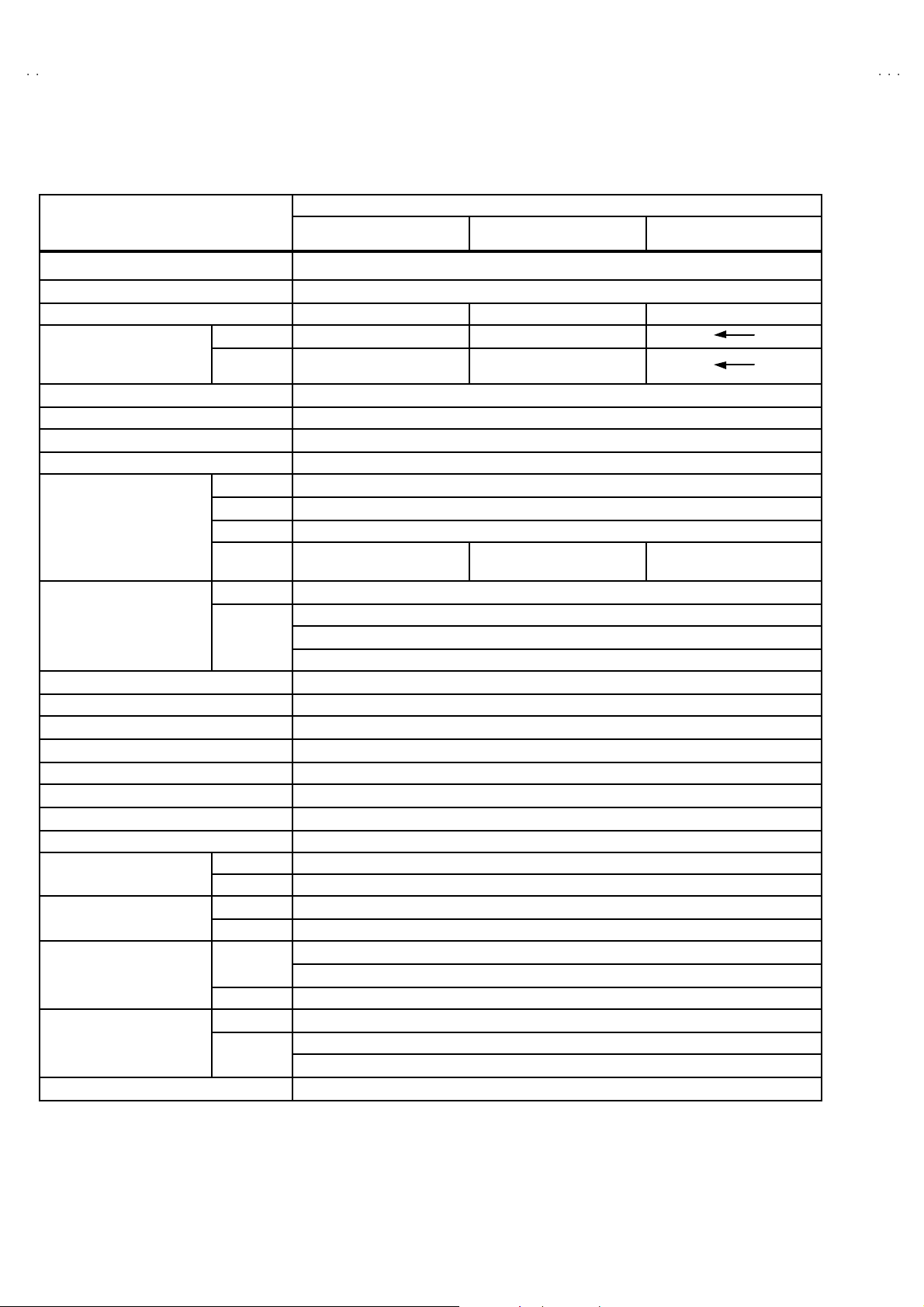
SPECIFICATIONS
Content
ITEM
Dime nsions (WxHxD) 78.4 × 58.2 × 49.3 cm
Weight 46.2 kg
TV RF S ys tem B/G B/G, L B/G, D/K, K1
TV Mode PAL PAL / SECAM
Colour System
Teletext Syst em Fastext / Toptext
Stereo System German + NICAM
Tuning System Frequenc y Synt hesizer Tuning System
Number Of CH memory position 100 ch
Receiving Frequency
Intermediate Fr equency
Colour Sub Carrier Frequency PAL (4.43 MHz ), SEC AM (4.43MHz), NT SC (3.58MHz/ 4.43M Hz )
Aer i al In put Terminal 75 Ohm Unbalanced
Pow er I nput AC 220 ~ 240V, 50Hz
Pow er Cons um ption 150W(Max.) / 73W(Avg.)
Pi cture Tube 29 inch measured diagonally
Hig h Vo l t a g e 29.5kV (in cut-off service mode)
Speaker ( 77 ×1 28 mm ellips e type + Twe eter ) ×2
Audio Out put 12W + 12W
Input ( FRONT )
Output ( REAR )
Re m o te Control Un it VE-30015781 (RM-C85) , Battery size:AAA/R03 x 2
Vi deo Mode
VHF (VL) 46.25MHZ ~ 168.25MHz
VHF (VH) 175.25MHz ~ 463.25MHz
UHF 471.25MHz ~ 863.25MHz
CATV
VIF Carrier 38.9MHz
SIF Carrier
Video 1V p- p, 75 Ohm
Au dio (L/R) 500 mVrms, High Impedance
Video 1 Vp-p, 75 Ohm
Au dio (L/R)500 mVrms, Low Impedanc e
R ear Sid e
Front Side F AV (Video/Audio)
Front Side
R ear Sid e
AV29BF10ENS AV29BF10EPS AV29BF10EES
PAL / NTSC 3.58 /
NTS C 4.43
S1 -S 20 & S 21- S4 1
& S75-S79
32.4MHz (6.5MHz)
32.9MHz (6.0MHz)
33.4MHz (5.5MHz)
EXT 1 (Vi deo/A ud io/R GB)
EXT 2 ( Vi de o/A ud io /S- VH S)Input Terminal
Headphone jack (Stereo mini jack 3.5∅)
EXT 1 ( Vi d eo/Aud i o)Output Terminal
EXT 2 (Video/Audio) (Selected TV, AV1 or AV3)
PAL / SECAM / NTSC 3.58 /
NTS C 4.43
S1 -S 20 & S 21- S4 1
S1 -S 20 & S 21- S4 1
& S75-S77
Design & spec ifications are s ubjec t to change w ithout noti ce.
2
No.51936
Page 3
A
V29BF10ENS
A
S
A
S
V29BF10EP
V29BF10EE
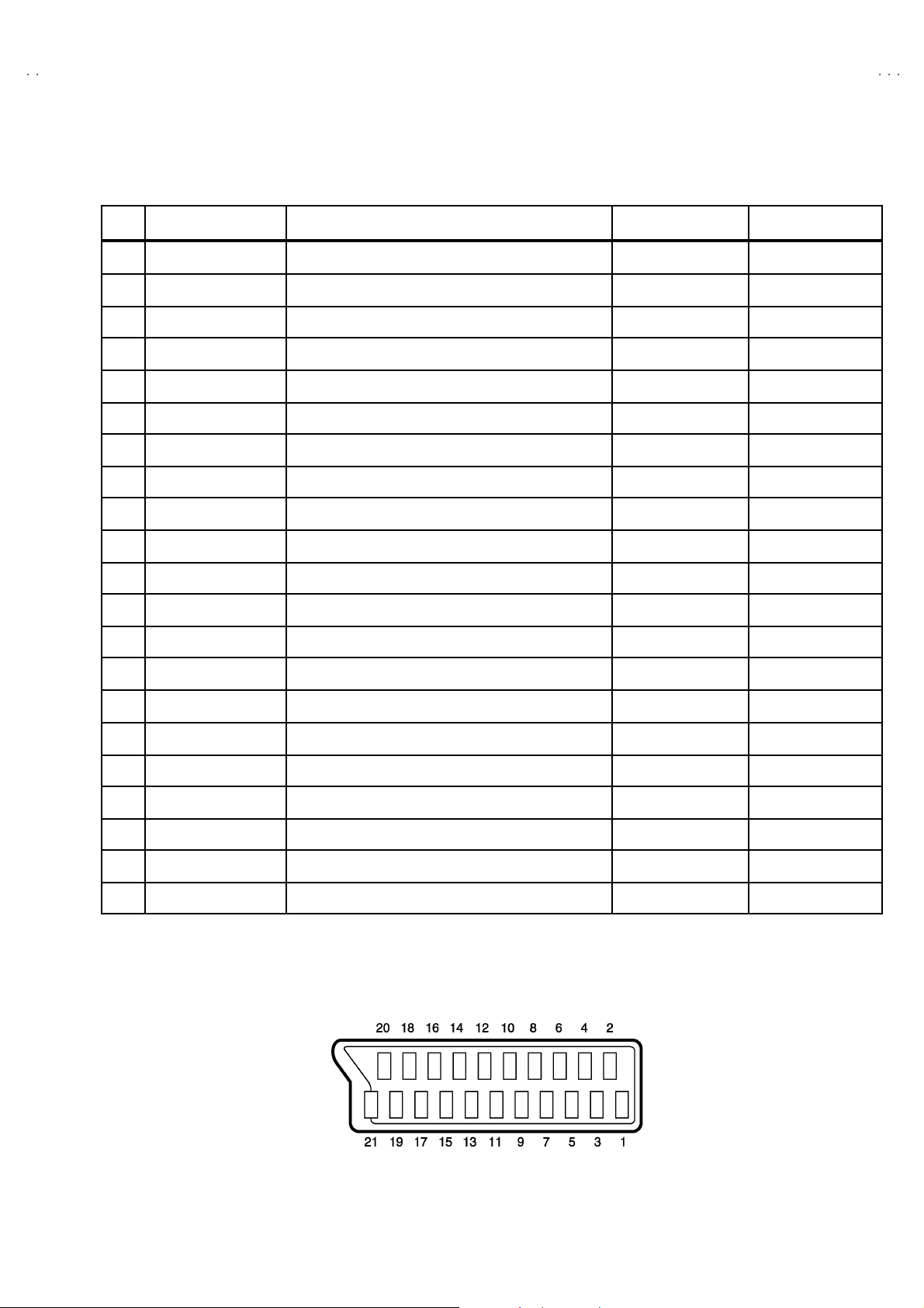
■
■21-pin Euro connector (S CART socket) : EXT 1 / EXT 2
■■
(P-P= Peak to Peak, S-W= Sync tip to white peak, B-W= Blanking to white peak)
Pin
Si gnal Designation Matchi ng Value EXT 1 EXT 2
No .
1 AUDIO R output 500mVrms(Nominal),Low impedance
2 AUDIO R inp ut 5 00 mVrm s (Nominal),High impe dance ○○
3 AUDIO L output 500mVrms(Nominal),Low impedance
4 AUDIO GND
5 GND (B) ○○
○
(TV OUT )
○
(TV OUT )
○○
○
(TV/LINE OUT)
○
(TV/LINE OUT)
6 AUDIO L in pu t 500mVrm s (Nominal), High impedan ce
B-W
7B input
FUN CTO N SW
8
(SLOW SW)
9 GND (G )
10 - NC -
11 G input
12
- NC -
1 3 GND (R)
1 4 GND (YS) ○ NC
1 5 R / C input
16 Ys input Low : 0 – 0.4, High : 1 - 3V, 75Ω○NC
1 7 GND(VIDEO output)
1 8 GND(VIDEO inpu t) ○○
19 VIDEO output
20 VIDEO / Y input 1V
700mV
Low : 0-3V, High : 8- 12V, Hi gh impeda nce
700mV
R : 700mV
C : 300mV
1V
, 75Ω○
B-W
, 75Ω○
B-W
, 75Ω
P-P
, 75Ω
S-W
(Negative going s ync), 75 Ω
S-W
(Negative going s ync), 75 Ω○○
○○
NC
○
○○
○○
○
(R/C)
○○
○
(TV)
NC
NC
○
(only C)
○
(TV/LINE OUT)
21 COMMON GND
○○
[Pin assignment]
No.51936
3
Page 4

A
V29BF10ENS
A
A
V29BF10EPS
V29BF10EES
SAFETY PREC AUTIONS
1. The design of this product contains special hardware, many
circuits and components specially for safety purposes. For
continued protection, no changes should be made to the original
design unless authorized in writing by the manufacturer.
Replacement parts must be identical to those used in the original
circuits. Service should be performed by qualified personnel
only.
2. Alterations of the design or circuitry of the products should not be
made. Any design alterations or additions will void the
manufacturer's warranty and will f urther relieve t he manufacturer
of r es p onsi bil i ty for per s o na l i njur y or p r oper ty dam age r esul ting
therefrom.
3. Many electrical and mechanical parts in the products have
special safety-related cha ra cteristics. T hese ch aracteristics are
often no t e v i den t f r om v is ua l i ns p ect i on n or c a n the pr o tec tio n
affor ded by them neces s ar il y b e ob t ained b y us in g r ep l ac em en t
com ponents ra t ed for hi g he r vo lt ag e, w att ag e, etc. R ep l acem ent
parts whic h have these special safety characterist ics are
identified in the parts list of Service manual. Electrical
com ponents having such featur es are identified by shading
on t he sche matic s and by (!!!! ) on the parts list in Service
manua l. The us e of a substitute r eplacemen t which do es not
have the same saf ety characteristics as the recommended
r epl ac em ent par t s h ow n i n th e par ts li st of Ser v i ce m anual m ay
cause shock, fire, or other hazards.
4. Don't short between the LIVE side ground and ISOLATED
(NEUTRAL) side ground or EARTH side ground when
repa iring.
Some model's p ower circuit is partly different in the GND. The
diff erenc e of the GND i s sh own b y the LI VE si de GND, the
ISO LAT E D(N EU TR AL) sid e GND a nd EA RTH si de GN D. D on't
short b etw ee n the L I VE s i de GN D a nd I S O LATED(N EU T R AL)
side GND or EARTH side GND and never measure with a
measuring apparatus (oscillosc ope etc.) the LIVE side GND and
ISOLATED(NEUTRAL) side GND or EARTH side GND at the
same time.
If above no te will no t be kept, a fuse o r any parts will be bro k en .
5. If any repair has been made to the chassis, it is recommended
that t he B1 setting should be checked or adjusted (See
ADJUSTMENT OF B1 POWER SUPPLY).
6. T he hi gh v olt a ge applie d to th e pi c tu r e t u be mu s t c on for m wi t h
th at sp ecified in S ervice m anual. E xcessive h igh volt age ca n
cause an increase in X-Ray emission, arcing and possible
component damage, t herefore operation under excessive high
voltage conditions should be kept to a minimum, or should be
prevent ed. If s evere arc ing occurs, remove t he AC power
immediately and determine the cause by visual inspection
(incorrect installat ion, cracked or melted high vo ltage harness,
p oor s o ld er i ng, etc.) . To m ai nt ai n t he p r ope r mi n im u m l e v el of
sof t X- Ray em ission, c omponents in the high vol tage circui try
including t he pict ure tu be must b e the exact r eplacem ents or
alternatives approved by the manufacturer of the complete
product.
7. Do not c heck high voltage by drawing an arc. Use a high volt age
meter or a high v oltage prob e wit h a V TVM . Discha rg e the
picture tube before attempting meter connection, by c onnecting
a cl i p le ad to t h e gr ou nd f ra me a nd c onn ec ti n g t h e other end of
t he le ad through a 10kΩ 2W resi s to r to the an od e but t on.
8. W hen se r vic e is r equ ir e d, ob ser v e the or i gi na l l ea d dr es s. E x tr a
pr ecaut i on shou ld b e g i ve n t o as s ur e corr ec t l ea d dr ess i n the
high voltag e circuit a rea. W here a s hort circuit h as occu rre d,
th os e comp on ent s that i ndi ca t e ev idence of over heati ng s ho ul d
be replaced. Always use the manufacturer's replacement
components.
9. Isolation Che ck
(Safety for Electr ical Shock Hazard)
After re-assembling the product, always perform an isolation
check on the exposed metal parts of the cabinet (antenna
terminals, video/audio input and output terminals, Control knobs,
metal cabin et, screwheads, e arphone jack, control sh afts, etc.)
to be sure th e pr oduct is s afe to o per ate with out dan ger of
el ectric al shoc k.
(1) Diele ctric Stre ngth Test
The i so l at ion be tw een t he AC pr im a ry c i rcu i t an d al l me tal p ar ts
exposed to the us er, particularly any expos ed metal part having a
r etu rn pat h to t he c hass is s ho ul d wi ths tand a vol tage of 3000 V
A C (r.m.s.) for a perio d o f one s econd.
( . . . . W it hst an d a v o lt ag e of 1 100V A C ( r .m.s .) t o an ap pl i ance
r ate d up t o 12 0V, an d 3 000V AC ( r .m.s.) t o an appl i an c e r ated
200V or m ore , for a period of one s econd. )
This method of test requires a test equipment not generally found
in the service trade.
(2) L eakage Curr ent Check
Plug the AC line c ord directly into the AC outlet (do not use a line
isolation transformer during this check.). Using a "Leakage
Current Tester", measure the leakage current from each exposed
metal part of the ca bine t, p art icular ly any e xpos ed metal part
having a return path to the chassis, to a known good earth
gr ou nd (w a ter pi pe, e tc .) . An y leak a ge c ur r en t m ust not e x ceed
0 .5m A AC (r.m.s. ).
However, in tropical area, this must not exceed 0.2mA AC
(r.m.s.).
"
" Alternate Check Method
""
Plug the AC line c ord directly into the AC outlet (do not use a line
isolatio n tran sformer during t his che ck.) . Use an AC voltmeter
havi ng 100 0 ohms per vol t or m ore sens it ivity in the fo llowing
m ann er . C on nec t a 150 0Ω 10W res istor par alle le d b y a 0 . 1 5µF
AC - ty pe capa c it or bet we en an expos ed metal part a nd a k no wn
good e arth gr oun d (wa ter pi pe, etc.). Meas ure th e AC vo ltage
across the resistor with the AC voltmeter. Move the resistor
connec ti on t o e ach ex p os e d me t al par t , parti c ul ar l y any exposed
m etal p ar t hav i n g a r eturn pat h to t he chas s i s, and m easu r e t h e
AC vol tage ac ro s s the resist or . N o w , re v er se t h e pl u g i n th e A C
outlet and repeat each measurement. Any volt age measured
must not exceed 0.75V AC (r.m.s.). This corresponds to 0.5mA
A C (r.m.s.).
Howeve r, in tropica l are a, this mu st n ot exce ed 0 .3V AC ( r .m.s .).
This c orrespo nds to 0.2 mA AC (r.m.s.).
AC VOL TM ETE R
(HAVING 1000 Ω /V,
OR MORE SE NSI TIV ITY)
0.15μF AC-TYPE
PL ACE THI S PRO BE
1500 Ω 10W
G OOD E AR TH GR O UN D
ON EACH EXPO SED
MET AL PA RT
4
No.51936
Page 5
A
A
S
A
S
FEATURES
V29BF10ENS
V29BF10EP
V29BF10EE
1. It is a remote controlled col or television.
2. 10 0 pr og r am s fr om VH F , UH F b an ds or cabl e c ha nn el s can be
preset.
3. It can tune cable channels.
4. Controlling the TV is very easy by its menu driven s ystem.
5. It has t w o Eur oc on nec t or s ock et s for e xt er n al d ev i ce (s u c h as
video recorder, video games, audio set, etc.)
6. F r ont AV Input av ail abl e.
7. Stereo s ound s ystems (German + Nicam) are available.
8. Full function Teletext (Fastext, Toptex t).
9. It is possible to connec t headphone.
10. Direct channel access.
11. AP S (Automat ic Programming System).
12. All programs can be named.
13. Forward or backward automatic tuning.
14 . Autom at ic sou nd mu t e wh en no transmi ss i on .
15 . 5 mi nu t es af t er t he br o adc as ti ng ( c los ed ow n) , the T V s wit ch es
itself automatically to stand-by mode.
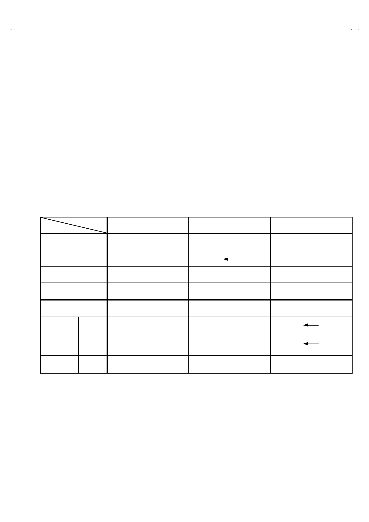
MAIN DIFFEREN CE LIST
MODEL No.
Parts Name
MAIN PWB VE-20082209 VE -20083311 VE-20082155
CRT SOCKET PWB VE-20062535 VE-20072781
AV29BF10ENS AV29BF10EPS AV29BF10EES
F CARTON BOX VE-50022390 VE-50022790 VE-50022788
INST BOOK VE-50022402 VE -50022856 VE-50022857
TV RF system B/G B / G, L B/G, D/K, K1
TV PAL PAL / SECAM
Colour
system
Receiving
Frequenc y
VIDEO
CATV
PAL
NTS C 3.58
NTS C 4.43
S01-S41
S75-S79
PAL / SECAM
NTS C 3.58
NTS C 4.43
B/G : S01- S41 / S75 - S79
L : S01-S41 / S75-S77
B/G : S01-S41 / S75 -S79
D/K : S01-S41
No.51936
5
Page 6

A
V29BF10ENS
A
A
V29BF10EPS
V29BF10EES
SPECIFI C SERVICE INSTRUCTIONS
DISASSEMBL Y PROCEDURE
REMO VI NG THE REAR CO VE R
1. Remove the 8 screws marked A.
2. Remove the 4 screws marked B.
3. Withdraw the rear cover toward you.
REMO VI NG THE MAIN PWB
" After re moving the rea r c over.
1. Draw out back and remove the MAIN PWB ASS’Y,
CAUTIONS)
Be caref ul enough when developing a main chassis.
The wire of a POWER T R ANS FE R does no t se para te and sh ort- circuit with ot her pa r ts.
REMO VI NG THE FRONT AV + HEADP HONE JACK BO ARD ASS ’Y
"
After re moving the rear cover.
1. Remove the 2 screws marked C, and remove the FRONT AV + HEADPHONE JACK BOARD ASS’Y.
REMO VI NG THE FRONT CONTROL PWB
"
A fter removing the rear c over.
1. Remove the MAIN PW B ASS’Y.
2. Remove the 3 screws marked D, and remove the FRONT CONTROL PW B.
REMO VI NG THE SPEAKER
"
A fter removing the rear c over.
1. Remove the 4 screws marked E, and remove the WOOFER SPEAKER.
2. Remove the 2 screws marked F, and remove the TWEETER SPEAKER.
3. Remove an opposite side similarly.
6
No.51936
Page 7

A
A
S
A
S
B
(×4)
V29BF10ENS
V29BF10EP
V29BF10EE
A
(×8)
REAR COVER
MAIN PWB
E
(×4)
SPEAKER
(WOOFER)
F
(×2)
SPEAKER
(TWEE TER)
C
(×2)
E
(×4)
F
(×2)
D
(×3)
FRONT
CONT RO L
PWB
FRONT CABINET
FRONT AV +
HEADPHONE JACK
PWB
No.51936
7
Page 8

A
V29BF10ENS
A
A
V29BF10EPS
V29BF10EES
SETTING OF THE LAS T MEMORY FOR SHIPMENT
■
■ USER SETTING VALUES
■■
Set ti ng I tem Setting Value Setting I tem Setting Value
SOUND MENU FE ATURE MENU
BASS CENTER SLEEP TIMER OFF
TREBLE
↑
CHILD L OCK OFF
BALANCE
EFFECT OFF
PICTURE MENU INSTALL TV CONFIG. MENU
BRIGHTNESS LANGUAGE ENGLISH
COLOUR COUNTRY ?
CONTRAST EXT-2 OUTP UT TV
SHARPNESS
HUE (on ly NTSC)
PICTURE MODE AUTO
Thes e adjust are automatically
restored when APS bit in Service
menu is set.
The proc edu re f or setting APS
b it is describ ed bellow.
↑
■ SETT ING APS BIT IN SERVICE MENU
1) Enter service menu in TV mode by pressing “INFO” and “MUTI NG” keys simultaneously. Serv ice Menu will appear.
2) Select OPTIONS by press ing Up/Down keys on remote control unit.
3) Enter OPTIONS by pressing Left/Right key s on remote control unit.
4) Select OPTION 8 by pressing Up/Down keys on remote control unit.
5) Selected bit in one OPTION is shown by blinking character. Select B2 by pressing Left/Right keys on remote control unit.
DO NOT CHANGE ANY OTH ER BIT.
6) Press digit key “1 ” to set APS bit.
7) Press “STANDARD” key on remote control unit to exit service mode.
8
No.51936
Page 9

A
A
S
A
S
SERVICE ADJUSTMENTS
ADJUSTMENT PREPARATION
1. Y ou ca n ma ke t he n e cessa ry ad ju st m e n ts f or t h is u n it wi t h
either the Remote Control Unit or With the adjustment tools
and part s a s given below.
2. Ad justment with the Remote Control Unit is made on the
basis of the initia l setti ng va lues, however, the new sett ing
values which s et the screen to its optimum condition may
differ from the initial settings.
3. Make sure that AC power is turned on correc tly.
4. Turn on th e power for s et an d test eq uip ment bef ore use , and
start the adjustment procedures after waiting at least 30 minutes.
5. U nl es s ot he r wi se s pecif i ed, pr epar e t he mo s t s u it ab le r ec ep ti on
or input signal for adjustment.
6. N ev er tou c h any ad j us tm en t par ts whic h ar e n ot s p ec i fi ed in the
list for thi s adju stment - v ariable resistors, transf ormers,
condensers, etc.
7. Presetting before adjustment.
U nles s ot her w i se s pec if i ed i n t he adj us tm e nt i nst r uctions , pres e t
the following functions with the remote c ontrol unit:
VIDEO STATUS STANDARD
TINT / COLOUR
PICTURE/BRIG HT
DETAIL
V29BF10ENS
V29BF10EP
V29BF10EE
CENTER
ADJUSTMENT EQUIPMENT
1. DC voltmeter (or digital voltmeter)
2. Signal generator (Pattern generator)[PAL/SECAM/NTSC
3 . Remo te control unit
MAIN PARTS LOCATIONS
FRONT AV + HEADPHONE
JA CK PWB
FRONT
VIDEO
HEADPHONE J ACK
RL
AUDIO
IC500
MICO M
LED
IC502
MEMO RY IC
]
FRONT CONTROL PWB
REMOCON
RECEIVER
MENU
MAIN PWB
(+)
(+) (-)
(-)
(+)(+)
(-)(-)
PROG
/Ch.
(+)
(+) (-)
(-)
(+)(+)
(-)(-)
VOL
TOP
FRONT
FBT
TUNER
(Indicated [150/115V]
on the bottom side)
B1
No. 51936
UPPER : FOCUS VR
LOWER : SCREEN VR
9
Page 10

A
V29BF10ENS
A
A
ADJUSTMENT SCREEN
A
(
)
y
V29BF10EPS
V29BF10EES
BASIC OPE RATION SERVICE MENU
■
■ HO W TO E NTER THE S ERVICE MODE
■■
1) Press the INFORMATION key and MUTI NG key of
REMOTE CO NT ROL UNIT simu ltaneously.
■■■■
SELECTION OF ADJUSTMENT ITEMS
1) Press the UP ( ) o r DOWN ( ) key and select
the service menu item.
2) Press the LEFT ( ) or RIGHT ( ) key and
enter ADJU STMENT SCRE EN.
3) Select the ADJUST No., use UP ( ) / DOWN ( )
key of remote control unit.
4) To change the selected parameter, us e LEFT ( )
and RIGHT ( ) key.
■ HOW TO EXIT SERVICE MOD E
1) Pr ess the STANDARD Ke y on REMOTE CONTROL UNIT.
■■■■
ADJUSTMENT SERVICE MENU
ADJUSTME NT ITEM
AGC 03 AGC
IF-PLL NEGATIVE 04 IF-PLL Negative
IF-PLL POSITIVE 05 IF-PLL P ositive
VERTICAL ZOOM
VE RTICA L SCRO LL
4 : 3 HORIZONTAL SHIFT
VERTICAL SLOPE
VERTICAL AMPLITUDE
S-CORRECTION
VERTICAL SHIFT
EW WIDTH
EW PAR ABOLA WIDT H
EW UPPER CORNER
PARABOLA
EW TRAPEZIUM
HORIZONTAL
PARALLELOGRAM
BOW
LOWER CORNE R
PARABOLA
DO NOT A DJUST 38~ 88 DO NOT ADJUST
ADJUST
No .
00 White Point RED
01 White Point G RE E NWH ITE BALANCE
02 White Point BLUE
06 Y-Delay PAL
07 Y-Delay SECAMLUMINANCE DELAY
08 Y-Del ay NTS C
10 4 : 3 PICTURE MODE
24 16 : 9 PICTURE MODE
11 4 : 3 PICTURE MODE
25 16 : 9 PICTURE MODE
12 4 : 3 PICTURE MODE
26 16 : 9 PICTURE MODE
13 4 : 3 PICTURE MODE
27 16 : 9 PICTURE MODE
14 4 : 3 PICTURE MODE
28 16 : 9 PICTURE MODE
15 4 : 3 PICTURE MODE
29 16 : 9 PICTURE MODE
16 4 : 3 PICTURE MODE
30 16 : 9 PICTURE MODE
17 4 : 3 PICTURE MODE
31 16 : 9 PICTURE MODE
18 4 : 3 PICTURE MODE
32 16 : 9 PICTURE MODE
19 4 : 3 PICTURE MODE
33 16 : 9 PICTURE MODE
20 4 : 3 PICTURE MODE
34 16 : 9 PICTURE MODE
21 4 : 3 PICTURE MODE
35 16 : 9 PICTURE MODE
22 4 : 3 PICTURE MODE
36 16 : 9 PICTURE MODE
23 4 : 3 PICTURE MODE
37 16 : 9 PICTURE MODE
DISCRIPTION
SERVICE
PARAMETER
VALUE
MUTING key
UP / DOWN
(
/
INFORMATION
key
SERVICE
ADJUST…..
OPTIONS…..
SERVICE MENU SCREEN
ADJUST *** ******
** *
IN. DOW N
REMOTE CONTROL UNIT key NAME
) key
DJUS T No.
PARAMETER
ST ANDARD k ey
LEFT / R IGHT
/
ke
10
No. 51936
Page 11

A
A
S
A
S
ADJUSTMENTS
Item
SCREEN
VOLTAGE
Adjus tment
Measuring
instrument
Signa l
Gen erator
Remote
Control
unit
SERVICE
ADJUST…..
OPTIONS…..
Test point Adjustment part Descr iption
SERVICE MENU
SCR EEN VR
[FBT]
OPTI ON 02
V29BF10ENS
V29BF10EP
V29BF10EE
1. Receive a PAL colour bar.
2. Enter the option settings in the SERVICE MENU.
3. Press the UP / DOW N ( ▲/ ▼) key, and Enter Option 0 2.
4. To change bit 6, c ome on to it by using L / R (
make it “1” by pressing “1” whit e bit 2 is blinking.
5. Observe the thin horizontal blue-white line in the middle of the
sc r een , and adjus t t he l o we r VR of th e FB T, u nti l the li ne is in
its thinn est visible thickness.
6. T he n ma k e Opt i on 02 b i t 6 “0 ” , by p r es s ing “0 ” on th e r em ote
control u nit, althou gh you do not see any picture.
/
) key and
FOCUS
Adjus tment
SELECT OPTION menu
FBT
FOCOUS
SCREEN
Signa l
gener ator
FOCUS VR
[FBT]
1. Receive a PAL circle pattern.
2. A d ju st t he upp er V R of t he F BT , u nti l you g et the O pti m um
fo cus, the sharpest picture.
B1
VOLTAGE
check
DC
Voltmeter
Marked
[150/115V]
on t he
MAIN PWB
No. 51936
1. Check whether the voltage at the point named and silk
screened as “150 / 115V” on the MAIN PWB is 150V DC.
11
Page 12

A
V29BF10ENS
A
A
)
)
)
V29BF10EPS
V29BF10EES
Item
WHITE
BALANCE
Measuring
instruments
Signa l
gener ator
Test point A djustment part Description
ADJUS T 00
(Whi te point
ADJUS T 01
(White point
ADJUS T 02
(Whi te point
-
GREEN
- BLUE
- RE D
[LOW LIGHT]
1. R ec ei ve a wh ole bl ac k sig na l.
2. Adjust the <Adjust 00>, <Adjust 01>, <Adjust 02>, in the
SERVICE MENU so that the entire screen do not shine black.
[HIGH LIGHT]
1. Receive a white and blac k signal (colour off).
2. Adjust the <Adjust 00>, <Adjust 01>, <Adjust 02>, in the
SE RV I CE M EN U s o that th e whiteness i n t he screen bec om e
sharp.
AGC
Ad justment
IF-PLL
NEGATIVE
Ad justment
IF-PLL
POSITIVE
Ad justment
DC
voltmeter
ADJUS T 03 1. Receive a any broadc ast.
2. Select <ADJ UST 03 > from SERVICE MENU
3. Connect a DC voltmeter to pin 1 of the tuner. Change the
AGC p ar am et e r unt i l you s ee 3.7 0V DC on v olt m et er di s play.
ADJUS T 04 1. Select <ADJ UST 04 > from SERVICE MENU.
2. Adjustment value is s et to 80 as a default value.
ADJUS T 05 1. Select <ADJ UST 05 > from SERVICE MENU.
2. Adjustment value is s et to 80 as a default value.
12
No. 51936
Page 13

A
V29BF10ENS
A
S
A
S
V29BF10EP
V29BF10EE
Item
LUMIN ANCE
DELA Y
Ad justment
Measuring
instruments
Signa l
gener ator
Test point Adjustment part Descr iption
Adjust 06 [ Y-Delay PAL ]
1. Receive a PAL colour bar signal.
2. Select <Adju st 06 > from SERVICE MENU.
3. Ad ju s t Y- D el ay PAL t il l t he c o l our tr ansi ents on t h e c olour
b ar of the patter n bec o me as s h ar per a nd c o l our s bet w een
transients do not mix with each other as possible.
Note: If the S AW filter is one of the G1965M, J1951M, K2958M,
K2962M, G3957M, K6256K, K6259K or M1963M, there is
constant group delay distortion, so for an equal delay of
the luminance and chrominance signal the delay must be
set at a value of 160nS. Th is means the adju st m ent must
be set t o the ma ximu m v alue.
Adjust 07 [ Y-Delay SECAM ]
1. Receive a SECAM colour bar sign al.
2. Select <Adju st 07 > from SERVICE MENU.
3. Adjust Y-Delay SECAM till t he co lour t ra nsien ts o n the
col o ur bar of the p att er n b ec o me as s h ar per an d c o l our s
between transients do not mix with each other as possible.
Note: If the SAW filter is one of the G1965M, K2958M,
K2 962 M, G 3957M , K62 56 K or K 6259K , ther e i s c on s tan t
group delay distortion, s o for an equal delay of the
l um inance an d c hr o mi n anc e s i gn al the del ay mu st be s e t
at a v alue of 16 0nS. Thi s me ans th e ad ju s tm en t m ust b e
set to the maxim um value.
Adjust 08 [ Y-Delay NTSC ]
1. Receive a NT SC colour bar signal.
2. Select <Adju st 08 > from SERVICE MENU.
3. Adjust Y-Delay NT SC till the colour transients on the colour
b ar of the patter n bec o me as s h ar per a nd c o l our s bet w een
transients do not mix with each other as possible.
Note: If the SAW filter is M1963M, there is constant group delay
disto rtion, so f or an equal delay of the lumin anc e and
chr omi n anc e s i gn al th e delay mu s t b e s et at a v al u e of
160nS . This m eans the a djust me nt must b e se t to the
ma ximum va lue.
No. 51936
13
Page 14

A
V29BF10ENS
A
A
V29BF10EPS
V29BF10EES
Item
VERTICAL
ZOOM
Ad justment
VERTICAL
SCROLL
Ad justment
4 : 3
HORIZONTAL
SHIFT
Ad justment
Measuring
instruments
Signa l
gener ator
Signa l
gener ator
Signa l
gener ator
Test point Adjustment part Descr iption
Adjust 10 ( 4 : 3 )
Adjust 24 ( 16 : 9 )
Adjust 11 ( 4 : 3 )
Adjust 25 ( 16 : 9 )
Adjust 12 ( 4 : 3 )
Adjust 26 ( 16 : 9 )
1. Receive a PAL circle test pattern .
2. Set < 4 : 3 aspect mode >.
3. Select < ADJUST 10 > from SERVICE MENU.
4 . Change vertica l z oo m till y ou see the upper an d lower lim it
of th e circle a s cl ose to th e uppe r and l owe r limit of th e
picture tube as possible.
5. Set < 16 : 9 aspect mode >.
6. Ad ju s ts with the s tep wh ich i s the sa me above fr om 3 t o 4
about the 16 : 9 aspect mode, too.
1. Receive a PAL circle test pattern.
2. Set < 4 : 3 aspect mode >.
3. Select < ADJUST 11 > from SERVICE MENU.
4. Cha nge vertica l scr oll til l you se e th e cir cle exact ly in the
middl e of the scr een .
5. Set < 16 : 9 aspect mode >.
6. Ad ju s ts with th e s tep w hi c h is the s am e ab ov e f r om 3 t o 4
about the 16 : 9 aspect mode, too.
1. Receive a RE D PURITY test pattern.
2. Set < 4 : 3 aspect mode >.
3. Select < ADJUST 12 > from SERVICE MENU.
4. Change horizontal shift till the picture is horizontally
cen tered. Check whet her t his adjust ment is correct aft er
com pl e t i ng Ser vi c e Mo de Ad ju s tm en t.
5. Set < 16 : 9 aspect mode >.
6. Ad ju s ts with the s tep wh ich is th e s am e abo v e fr om 3 t o 4
about the 16 : 9 aspect mode, too.
VERTICAL
SLOPE
Ad justment
VERTICAL
AMP LIT UDE
Ad justment
Signa l
gener ator
Signa l
gener ator
Adjust 13 ( 4 : 3 )
Adjust 27 ( 16 : 9 )
Adjust 14 ( 4 : 3 )
Adjust 28 ( 16 : 9 )
1. Receive a CROSS-HATCH signal.
2. Set < 4 : 3 aspect mode >.
3. Select < ADJUST 13 > from SERVICE MENU.
4. C ha nge v e rt ic al sl op e t i ll t he s iz e of squar es on b oth t he
up per a nd l owe r par t of t est p att er n bec om e e qu al t o th e
squares laying on the vertical center of the test pattern.
5. Check and readjust VERTICAL SLOPE item if the
ad j ust m en t bec om es im pr oper af t er so me ot her g eome t r ic
adjustments are done.
6. Set < 16 : 9 aspect mode >.
7. Ad ju s ts with the s tep wh ich i s the sa me above fr om 3 t o 5
about the 16 : 9 aspect mode, too.
1. Receive a PAL tes t pattern signal.
2. Set < 4 : 3 aspect mode >.
3. Select < ADJUST 14 > from SERVICE MENU.
4. C ha nge v er ti c al s lo pe ti ll ho ri zont a l bl ack l i nes o n both the
up per an d l ow er p ar t of the t est p at t er n bec om e ver y c l ose
to the uppe r a nd l ow e r ho ri zo nt a l s ides of pict ur e t ub e an d
nearly about to disappear.
5. Check and read just VE RTICAL AMPL ITU DE item if the
ad j ust m en t bec om es im pr oper af t er so me ot her g eome t r ic
adjustments are done.
6. Set < 16 : 9 aspect mode >.
7. Ad ju s ts with the s tep wh ich i s the sa me above fr om 3 t o 5
about the 16 : 9 aspect mode, too.
14
No. 51936
Page 15

A
V29BF10ENS
A
S
A
S
V29BF10EP
V29BF10EE
Item
S-CORRECTION
Ad justment
VERTICAL
SHIFT
Ad justment
EW WIDTH
Ad justment
Measuring
instrument
Signa l
gener ator
Signa l
gener ator
Signa l
gener ator
Test point Adjustment part Descr iption
Adjust 15 ( 4 : 3 )
Adjust 29 ( 16 : 9 )
Adjust 16 ( 4 : 3 )
Adjust 30 ( 16 : 9 )
Adjust 17 ( 4 : 3 )
Adjust 31 ( 16 : 9 )
1. Receive a PAL circle pattern signal.
2. Set < 4 : 3 aspect mode >.
3. Select < ADJUST 15 > from SERVICE MENU.
4. C ha nge S-c o rr ect i on ti l l th e middle part of the c i rcl e i s r ou n d
as pos si ble .
5. Set < 16 : 9 aspect mode >.
6. Ad ju s ts wi t h the s tep whi c h i s the s a me ab ov e fr om 3 to 4
about the 16 : 9 aspect mode, too.
1. Receive a PAL tes t pattern signal ( or the symmetrical signal
in the top and the bottom and on eith er side to find ).
2. Set < 4 : 3 aspect mode >.
3. Select < ADJUST 16 > from SERVICE MENU.
4. Change Vertical Shift till the test pattern is vertically centered,
i .e. hor i z on tal l i ne at the c e nter p atter n i s i n equ al dis t an c e
both to upper and lower side of the picture tube.
5. Check and readjust Vertical Shift item if t he adjust ment
b ec om es i m pr op er af ter s om e o ther geo m etr i c a dj ust m en ts
ar e do ne.
6. Set < 16 : 9 aspect mode >.
7. Ad ju s ts wi t h the s tep whi c h i s the s a me ab ov e fr om 3 to 5
about the 16 : 9 aspect mode, too.
1. Receive a PAL tes t pattern signal.
2. Set < 4 : 3 aspect mode >.
3. Select < ADJUST 17 > from SERVICE MENU.
4. Cha nge EW Width till th e ve rt ical black and white bars on
both left and right side of the pattern exactly disappear.
5. Set < 16 : 9 aspect mode >.
6. Adjusts with the step which is the same above from 3 to 4
about the 16 : 9 aspect mode, too.
EW
PARABOLA
WIDTH
Ad justment
EW
UPPER
CORNER
PARABOLA
Ad justment
Signa l
gener ator
Signa l
gener ator
Adjust 18 ( 4 : 3 )
Adjust 32 ( 16 : 9 )
Adjust 19 ( 4 : 3 )
Adjust 33 ( 16 : 9 )
1. Receive a PAL tes t pattern signal.
2. Set < 4 : 3 aspect mode >.
3. Select < ADJUST 18 > from SERVICE MENU.
4. Change EW Parabola Width till vertical lines clos e to the both
si des of t he p i c tur e fr ame b ec o me para l l el to v er ti c a l si de of
picture tube.
5. Check and readjust EW Parabola Width item if the
adjustm ent bec omes improp er aft er s ome ot her g eomet ric
adjustments are done.
6. Set < 16 : 9 aspect mode >.
7. Adjusts with the step which is the same above from 3 to 5
about the 16 : 9 aspect mode, too.
1. Receive a PAL tes t pattern signal.
2. Set < 4 : 3 aspect mode >.
3. Select < ADJUST 19 > from SERVICE MENU.
4. C ha nge EW Cor n er Par abola t i l l v er tical li n es at the cor n er s
of both s i des of pi cture f ra me bec o me ver ti cal and par al l el to
vertical corner sides of picture t ube.
5. Check and readjust EW Corner Parabola item if the
adjustm ent bec omes improp er aft er s ome ot her g eomet ric
adjustments are done.
6. Set < 16 : 9 aspect mode >.
7. Adjusts with the step which is the same above from 3 to 5
about the 16 : 9 aspect mode, too.
No. 51936
15
Page 16

A
V29BF10ENS
A
A
V29BF10EPS
V29BF10EES
Item
EW
TRAPEZIUM
Ad justment
HORIZONTAL
PARALLELO
-GRAM
Measuring
instrument
Signa l
gener ator
Signa l
gener ator
Test point Adjustment part Descr iption
Adjust 20 ( 4 : 3 )
Adjust 34 ( 16 : 9 )
Adjust 21 ( 4 : 3 )
Adjust 35 ( 16 : 9 )
1. Receive a CROSS-HATCH signal.
2. Set < 4 : 3 aspect mode >.
3. Select < ADJUST 20 > from SERVICE MENU.
4. C ha nge EW T r apez i um t i ll v er tic al l i ne s , es peci all y l in es at
th e s i d es of t h e pi c tu r e f ra m e b ec a me p ar al l el to th e both
si des of pi ct u re tu be as p os si bl e.
5. Check a nd read just EW Trapezium it em if t he adjust ment
becomes improper after s ome other geometric adjustment.
6. Set < 16 : 9 aspect mode >.
7. Ad ju s ts wi t h the s tep whi c h i s th e s a m e a bov e fr om 3 to 5
about the 16 : 9 aspect mode, too.
1. Receive a CROSS-HATCH signal.
2. Set < 4 : 3 as pect mode >.
3. Select < ADJUST 21 > from SERVICE MENU.
4. Change Horizontal Parallelogram to set vertical lines
orthogonal to the horizontal lines..
5. Check and readjust Horizontal Parallelogram item if t he
adjustm ent bec omes improp er aft er some oth er geo metr ic
adjustment.
6. Set < 16 : 9 aspect mode >.
7. Ad ju s ts wi t h the s tep whi c h i s th e s a m e a bov e fr om 3 to 5
about the 16 : 9 as pect mode, too.
BOW Signal
gener ator
EW
LOWER
CORNER
PARABOLA
Ad justment
Signa l
gener ator
Adjust 22 ( 4 : 3 )
Adjust 36 ( 16 : 9 )
Adjust 23 ( 4 : 3 )
Adjust 37 ( 16 : 9 )
1. Receive a CROSS-HATCH signal.
2. Set < 4 : 3 as pect mode >.
3. Select < ADJUST 22 > from SERVICE MENU.
4. Change Bow to straighten the vertical lines.
5. Check and r eadj ust Bo w it em i f the ad ju stment b ecomes
improper after some other geometric adjust ment.
6. Set < 16 : 9 aspect mode >.
7. Ad ju s ts wi t h the s tep whi c h i s th e s a m e a bov e fr om 3 to 5
about the 16 : 9 as pect mode, too.
1. Receive a CROSS-HATCH signal.
2. Set < 4 : 3 as pect mode >.
3. Select < ADJUST 23 > from SERVICE MENU.
4. Cha nge EW Lower Corn er Parabola till vertical lines at the
cor ners of both sides of pi cture frame beco me vert ic al and
parallel to vertical corner sides of picture tube.
5. C heck an d r eadjus t E W Low er C or n er Par abola i t em i f the
adjustm ent bec omes improp er aft er some oth er geo metr ic
adjustment.
6. Set < 16 : 9 aspect mode >.
7. Ad ju s ts wi t h the s tep whi c h i s th e s a m e a bov e fr om 3 to 5
about the 16 : 9 as pect mode, too.
16
No. 51936
 Loading...