

Page 1
AV28CT1E KS / AV28C T1EK
B
B
AV28CT1EPS / AV28CT1EP
SERVICE MANUAL
COLOUR TELEVISION
AV28CT1EKS / AV28CT1EKB
AV28CT1EPS / AV28CT1EPB
AV28 CT1 EIS
BAS IC CHASSIS
ⅡⅡⅡⅡ
JK
AV28CT1EIS
CONTENTS
!
SPECIFICATIONS
!
SAFETY PRECAUTIONS ・・・・・・・・・・・・・・・・・・・・・・・・・・・・・・・・
! WAR NING ・・・・・・・・・・・・・・・・・・・・・・・・・・・・・・・・
!
FEATURES・・・・・・・・・・・・・・・・・・・・・・・・・・・・・・・・
!
MAIN DIFFERENCE LIST ・・・・・・・・・・・・・・・・・・・・・・・・・・・・・・・・
! SPECIFIC SERVICE INSTRUCTIONS ・・・・・・・・・・・・・・・・・・・・・・・・・・・・・・・・
!
SERVICE ADJUSTMENTS
! PARTS LIST ・・・・・・・・・・・・・・・・・・・・・・・・・・・・・・・・
・・・・・・・・・・・・・・・・・・・・・・・・・・・・・・・・・・・・・・・・・・・・・・・・・・・・・・・・・・・・・・・・
・・・・・・・・・・・・・・・・・・・・・・・・・・・・・・・・・・・・・・・・・・・・・・・・・・・・・・・・・・・・・・・・
・・・・・・・・・・・・・・・・・・・・・・・・・・・・・・・・・・・・・・・・・・・・・・・・・・・・・・・・・・・・・・・・
・・・・・・・・・・・・・・・・・・・・・・・・・・・・・・・・・・・・・・・・・・・・・・・・・・・・・・・・・・・・・・・・
・・・・・・・・・・・・・・・・・・・・・・・・・・・・・・・・
・・・・・・・・・・・・・・・・・・・・・・・・・・・・・・・・・・・・・・・・・・・・・・・・・・・・・・・・・・・・・
・・・・・・・・・・・・・・・・・・・・・・・・・・・・・・・・・・・・・・・・・・・・・・・・・・・・・・・・・・・・・・・・
・・・・・・・・・・・・・・・・・・・・・・・・・・・・・・・・・・・・・・・・・・・・・・・・・・・・・・・
・・・・・・・・・・・・・・・・・・・・・・・・・・・・・・・・・・・・・・・・・・・・・・・・・・・・・・・・・・・・・・・・
・・・・・・・・・・・・・・・・・・・・・・・・・・・・・・・・・・・
・・・・・・・・・・・・・・・・・・・・・・・・・・・・・・・・・・・・・・・・・・・・・・・・・・・・・・・・・・・・・・・・
・・・・・・・・・・・・・・・・・・・・・・・・・・・・・・・・・・・
・・・・・・・・・・・・・・・・・・・・・・・・・・・・・・・・・・・・・・・・・・・・・・・・・・・・・・・・・・・・・・・・
・・・・・・・・・・・・・・・・・・・・・・・・・・・・・・・・・・・・・・・・・・・・・・・・・・・・・・・
・・・・・・・・・・・・・・・・・・・・・・・・・・・・・・・・・・・・・・・・・・・・・・・・・・・・・・・・・・・・・・・・
・・・・・・・・・・・・・・・・・・・・・・・・・・・・・・・・・・・・・・・・・・・・・
・・・・・・・・・・・・・・・・・・・・・・・・・・・・・・・・・・・・・・・・・・・・・・・・・・・・・・・・・・・・・・・・
・・・・・・・・・・・・・・・・・・・・・・・・・・・・・・・・
・・・・・・・・・・・・・・・・・・・・・・・・・・・・・・・・・・・・・・・・・・・・・・・・・・・・・
・・・・・・・・・・・・・・・・・・・・・・・・・・・・・・・・・・・・・・・・・・・・・・・・・・・・・・・・・・・・・・・・
・・・・・・・・・・・・・・・・・・・・・・・・・・・・・・・・・・・・・・・・・・・・・・・・・・・・・・・・・・・・・・・・
・・・・・・・・・・・・・・・・・・・・・・・・・・・・・・・・・・・・・・・・・・・・・・・・・・・・・・・・・・・・・・・・
・・・・・・・・・・・・・・・・・・・・・・・・・・・・・
・・・・・・・・・・・・・・・・・・・・・・・・・・・・・・・・・・・・・・・・・・・・・・・・・・・・・・・・・・
・・・・・・・・・・・・・・・・・・・・・・・ 4
・・・・・・・・・・・・・・・・・・・・・・・・・・・・・・・・・・・・・・・・・・・・・・
・・・・・・・・・・・・・・・・・・・・・・・ 6
・・・・・・・・・・・・・・・・・・・・・・・・・・・・・・・・・・・・・・・・・・・・・・
・・・・・・・・・・・・・・・・・・・・・
・・・・・・・・・・・・・・・・・・・・・・・・・・・・・・・・・・・・・・・・・・
・・・・・・・・・・・・・・・・・・・・・・・・・・・・・・・・・・・・ 33
・・・・・・・・・・・・・・・・・・・・・・・・・・・・・・・・・・・・・・・・・・・・・・・・・・・・・・・・・・・・・・・・
・・・ 5
・・・・・・
・・・ 6
・・・・・・
・・・・・・・・・・・・・ 7
・・・・・・・・・・・・・・・・・・・・・・・・・・
13
2
★ ST ANDARD CIRCUIT DIAGRAM ・・・・・・・・・・・・・・・・・・・・・・・・・・・・・・・・
1
COPYRIGHT © 2002 VICTOR COMPANY OF JAPAN, LTD.
・・・・・・・・・・・・・・・・・・・・・・・・・・・・・・・・・・・・・・・・・・・・・・・・
・・・・・・・・・・・・・・・・・・・・・・・・・・・・・・・・・・・・・・・・・・・・・・・・・・・・・・・・・・・・・・・・
・・・・・・・・・・・・・・・・ 2-1
・・・・・・・・・・・・・・・・・・・・・・・・・・・・・・・・
No.519 52
Mar. 2002
Page 2
A
B
A
B
A
S
REPLACEMENT OF MEMORY ICs
1. Memory ICs
This TV use memory ICs. In the memory ICs, there are memorized data
for cor r ectl y op erating th e video an d def l ection cir cu its . W h en r ep lac ing
memory IC s, b e s ure t o us e IC s wri tte n with th e initial values of da ta.
2. Procedure for replacing memory ICs
PROCE DURE
(1) Powe r off
Switch the p ower of f and un plug th e pow er cor d fro m t he ou tlet.
V28CT1EKS / AV28CT 1EK
V28CT1EPS / AV28CT 1EP
V28CT1EI
(2) Rep la ce ICs.
Be sure to use memory ICs writt en with the in it ial data values.
(3) Powe r o n
Plug th e p ower c ord i nt o the outlet a nd swit ch t he po we r on .
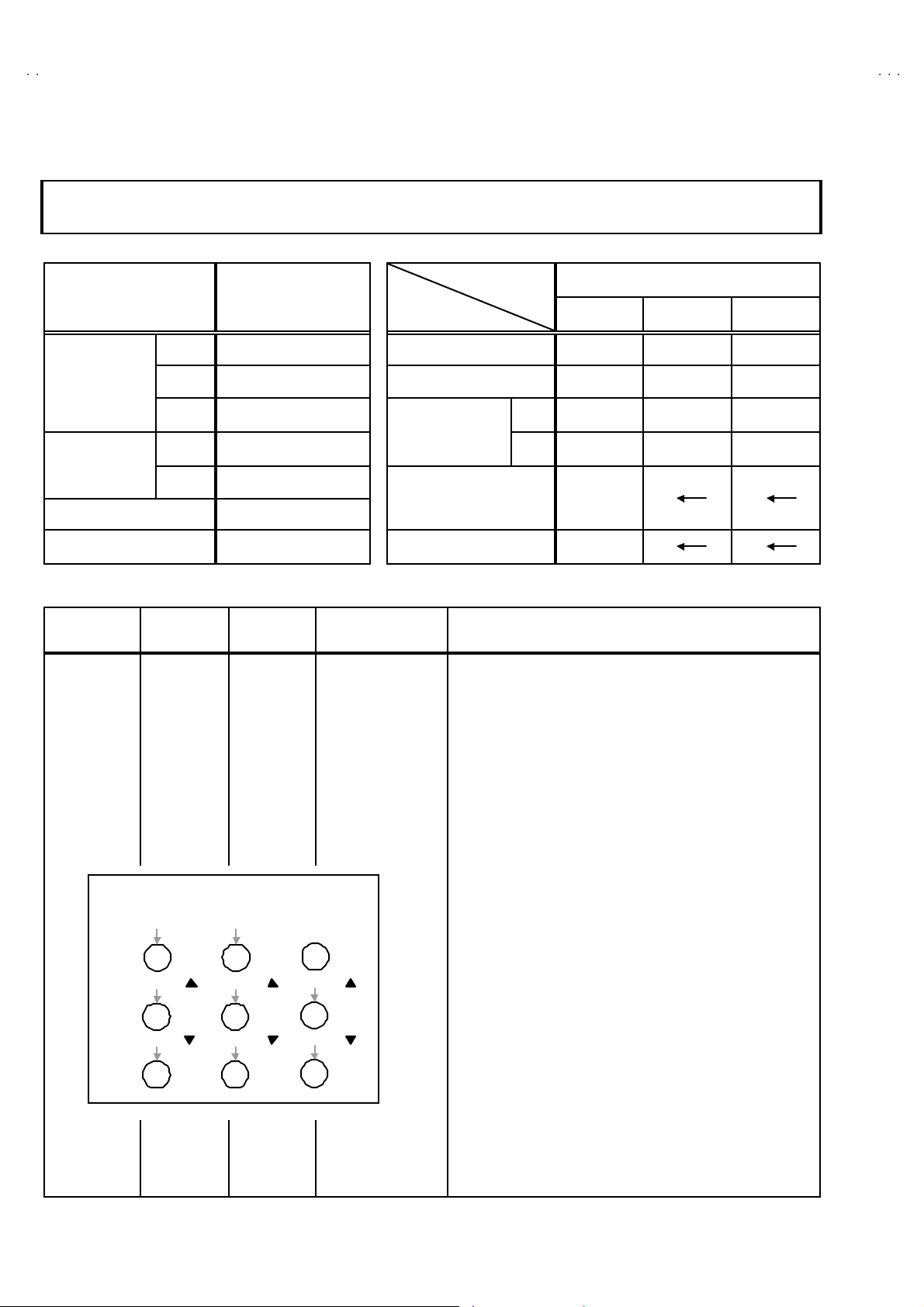
(4) Check an d s et SY STEM CONSTAN T SET :
It must not adjust wit hout sig nal.
****
1) Pr ess th e INFORMAT I ON ke y and th e MUT IN G k ey of th e
REMOTE CONTROL UNIT simultane ous ly.
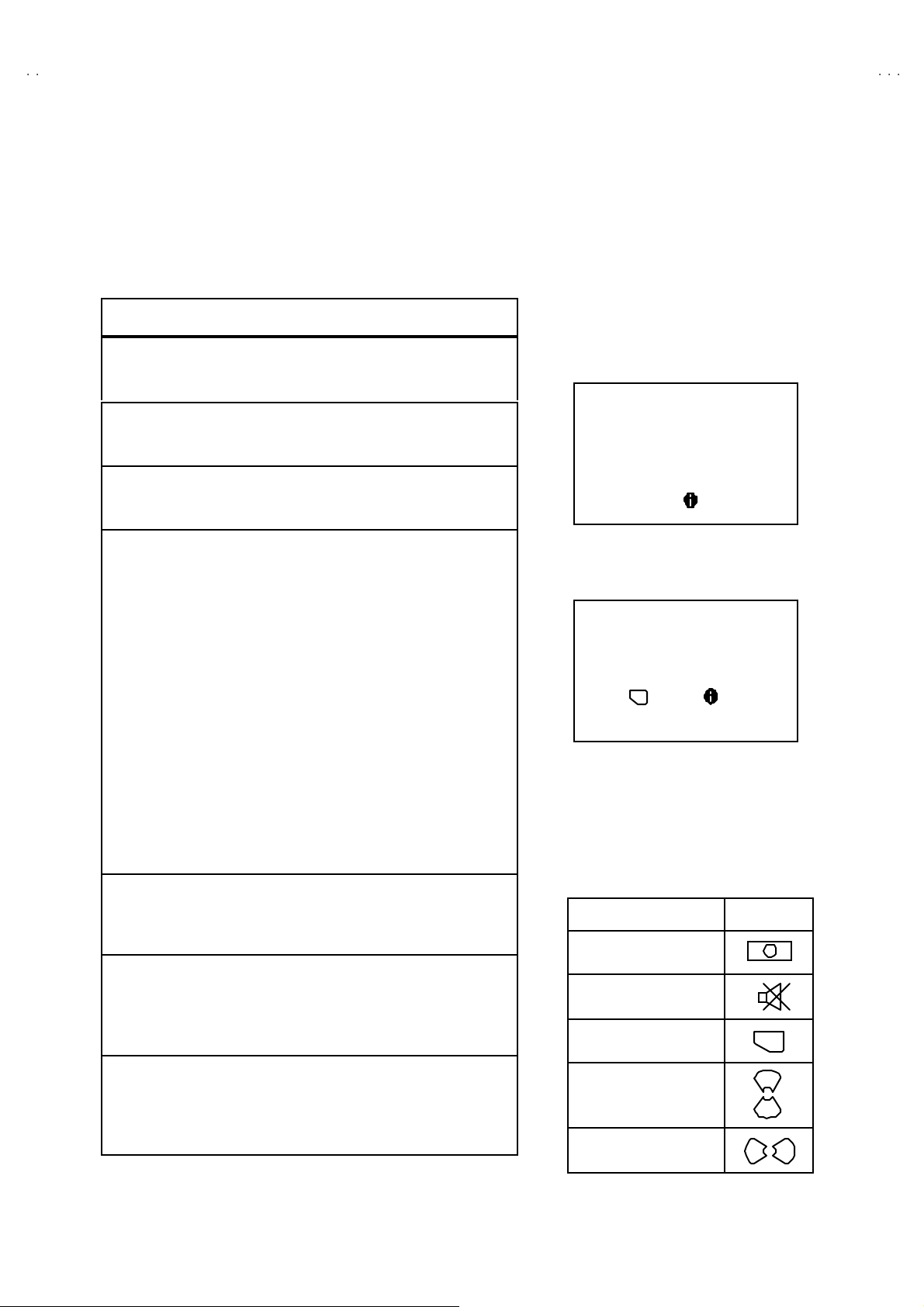
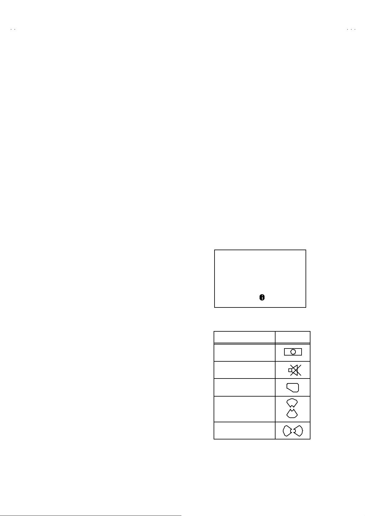
2) The SERVICE MENU screen of Fig. 1 will be displayed.
3) Whi le th e S ERVICE ME NU is displ a yed, p r ess t he
INFORMATION key and MUTING key simultane ously, and the
SYSTEM CONSTANT SET screen of Fig. 2 will be display ed.
4) Check the se tting va lues of the S YSTEM C ONST A NT SET of
Table 1. If the value is d ifferent, select th e s ettin g item with th e
FUNCTION U P/ DOWN key, and s et the correct va lue with the
FUNCTION - /+ ke y.
5) Press the MENU key to memorize the setting va lue.
6) Pres s t he IN FOR MATION ke y t wice, a nd r etu rn t o th e no rmal
screen.
SE RV ICE MEN U
1. IF 2. V/C
3. AUDIO 4. DEF
5. VS M PRES ET 6. VP S
7. AUTO PROGRAM (OFF)
1- 7 : SE LECT : EXI T
Fig.1
SY STE M CON ST AN T S ET
MO DE L= JK _EU R O (V
COUNTRY :
INCH :
MO DE L : W T
- + : STORE : EXIT
OK
JVC JK- II EU RO V00
******** - *****
Fig.2
*.****
**
**
)
(5) Setting of re cei ve ch anne ls
Se t the rec eive c h an ne l.
NAME OF REMOTE CONTROL KEY
Names of key
ke y
For setting , ref er to the OPERATIN G INSTRUCTIONS.
INFORMATION
iiii
(6) User se tting s
Check th e us er sett in g values of T ab le 2, an d if sett in g value is
MU T I N G
diff er ent , set the c orr ec t val u e.
For setting , ref er to the OPERATIN G INSTRUCTIONS.
OK
▼
▼
(7) Setting of SERV ICE MENU
Ve rif y the s et ting it ems of th e SER VIC E MENU of Tab le 3, an d r ese t
where necessary.
ME NU
FUNCTION UP/DOWN
For setting , ref er to the SERVICE ADJUSTMENTS.
▼
FUNCTION -/+
▼
No. 51952
11
Page 3
A
V28CT1EKS / AV28CT 1EKB
A
A
V28CT1EPS / AV28CT 1EPB
V28CT1EIS
SETT I NG VALU ES OF SYST EM CONS TANT SE T (TABLE 1)
Setting item Se tting content
AV28 CT1 EPS / EPB AV28 CT1 EIS AV 28CT1 EKS / EKB
Setting value
COUNT RY EP IR EK
INCH 28 28 28
MO DE L W T
EK EPIR
WT
3224 28
WR
USER SETTING VALUES (TABLE 2)
PICTURE SE TTING EX T SET TI NG
TINT
CONTRAST
BRIGHT
SHAR P
COLO UR
ECO MOD E
PICTURE F EAT URES FEATUR ES
AUT O VNR
COLOUR S YSTEM
4:3 AUT O ASPE CT
SOUND SETTING INSTALL
STEREO / Ⅰ・Ⅱ
BA SS
TR EBL E
BALANCE
HYPE R S OUND
COOL
REFER to VSM PRESET
NOTHING
AUT O
TV : Acco rding t o preset CH
EXT : AUTO
PA NO RA MI C
+8
CENTER
OFF
ID
S-IN
DUB BING
SLEEP TIMER
BLUE BA CK
CHI LD LO CK
DECODER (EXT-2)
LA NG UA G E
EDIT/MANUAL
DEMO OFF
BLANK
BLANK
EXT- 1→EX T-2
OFF
ON
ID : No.****
ALL CH OFF
OFF
ENGL ISH
PRES ET CH on ly
The others : BLANK
SERVICE MENU SETTING ITEMS (TABLE 3)
Setting item Setting value Se tting item Setting value
1. IF VCO 4. DEF. 1. V-SHIFT
2. V / C 1. CUT OFF
1. AUDIO
(Do not adju st)
2. DRI VE
3. BRIGHT
4. CONT.
5. COLO UR
6. HUE
7. BL ACK O FFS ET ( Onl y SEC AM)
8. SHAR P
9. PURITY
1. CONC LIMIT
2. A2 ID THR
3. AL C
4. BA SS
5. TR EBL E
5. VS M PRESE T
COOL
NORMAL
WARM
6. VP S
(Do not adju st)
7. AUT O PROG RAM
(Do not adju st)
2. V-SIZE
3. SUBT IT LE
4. H-CENT
5. H-S IZE
6. EW - PIN
7. TR APE Z
8. EW. COR. L
9. EW. COR. H
10. V. S- COR
11 . V- LIN
12. H- BL K-R
13. H- BL K- L
14. V-EHT
15 . H - EHT
16. EHT-GAIN
1. BRIGHT
2. CONT.
3. COLO UR
4. SHAR P
5. HUE
6. R DRIVE
7. B D RIVE
VP S
PDC
ON / O FF
12
No. 51952
Page 4

A
B
A
B
A
S
SERVICE ADJUSTMENTS
BEFORE STARTING SERVICE ADJUSTMENT
1. There ar e 2 w ays of ad ju st ing this TV: One is wi th the
REMOTE CONTROL UNIT and the other is the conventional
method using adjustment pa rts and components.
2. The s etting (adjustment) using the REMOTE CONTROL
UNIT is made on the basis of th e init ial setting values. The
se tting va lues which adj u st the scree n to t h e opt imum
condition can be different from the initial setting values.
3. Make s ur e th at c onn ect ion is c orrect l y made t o AC p ow er
source.
4. Tur n on th e pow e r of the T V and m eas u r ing instr um en t for
warmi n g u p for at l east 30 minut es b ef ore sta rt ing adju stment .
5. If th e r ec eive or i np ut si g nal is not speci fi ed , use t he m ost
ap prop riate s igna l f or a dj ust ment.
6. Never tou c h p ar ts ( suc h as var i ab le resist or s, tran sformers an d
condensers) not shown in the adjustment items of this service
adjustment.
7. Preparatio n f or ad j ustment ( pr es etting):
Unles s oth er wis e speci fi ed i n the a djust ment it em s, p r eset th e
follo wing funct io ns with the REMOTE CONTROL U NIT :
" Setting position
PICTURE MODE (VSM) NORMAL
SLEEP TIMER OFF
BALANCE CENTER
ZOOM PANORAMIC
V28CT1EKS / AV28CT 1EK
V28CT1EPS / AV28CT 1EP
V28CT1EI
MEASURING INSTRUMENT AND FIXTURES
1. DC voltmeter (or digit al voltmeter)
2. Oscilloscop e
3. Si gn al g enerat or (Patt ern g en erator) [ PAL / SE CA M / NTSC ]
4. Remote control unit
ADJUSTMENT ITEMS
●
B1 power supply check.
●
Adjustment of FOCUS.
●
IF ci rcuit a djust me nt.
●
VS M p r eset ad ju st s ettin g.
●
VIDEO / CHROMA circ uit adjustment.
●
DEFLECTION circuit adjustment.
●
H. BLANKIN G ADJUSTME NT.
●
AUDIO circuit adjustment. (Do not adjust)
No. 51952
13
Page 5
A
V28CT1EKS / AV28CT 1EKB
A
A
5
V28CT1EPS / AV28CT 1EPB
V28CT1EIS
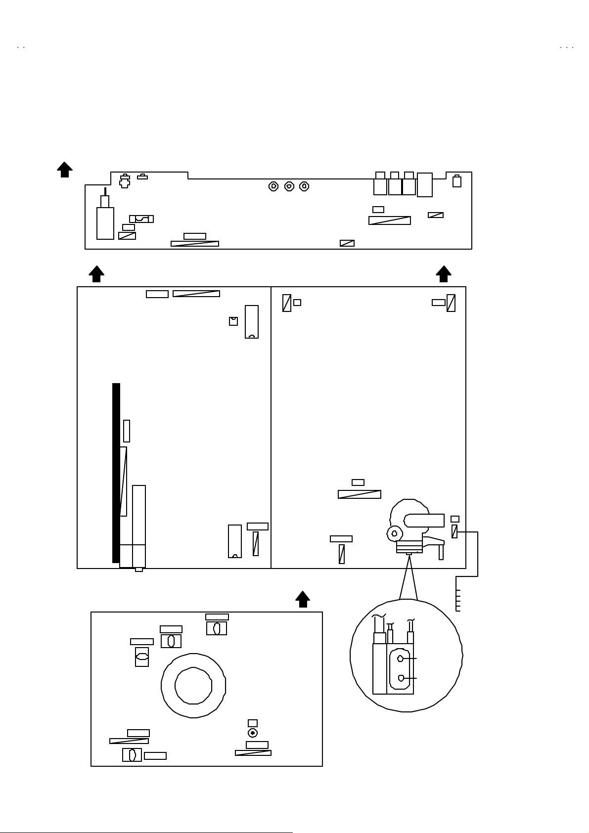
ADJUSTMENT LOCATIONS
FRON T
FRONT CONTROL PWB
F90 1
PW
POWER SW
FRON T
MAIN PWB POWER&DEF PW B
CN001
AV SEL PWB
CN006
CN001
MEMORY
IC702
IC701
F
SP R
SP L
FRON T
W DEG
TUNER
CRT SOCKET PWB
T P-47R
T P-47G
CN008
TP-E
IC301
CN008
(SOLDER SIDE)
T P-47B
E1
CN009
TOP
CN009
HV
X
1
1pin:B1( TP-91)
2pin:NC
3pin:NC
4pin:NC
5pin:GN D
FOCUS
SCREEN
14
No. 51952
Page 6
A
V28CT1EKS / AV28CT 1EK
B
A
B
A
S
y
y
V28CT1EPS / AV28CT 1EP
V28CT1EI
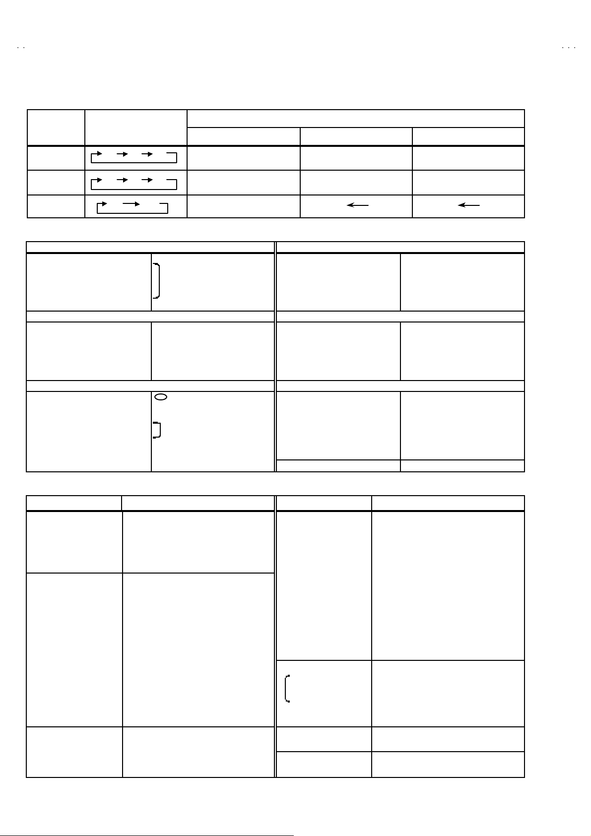
BASIC OPERATION SERVICE MENU
1. TOOL OF SERVICE MENU OPERATION
Operate the SERVICE MENU with the REMOTE CONTROL UNIT.
2. SE RVICE MENU ITEMS
With the SERVI CE MENU , v ar iou s s ett ings ( ad ju stments) c an b e m ade , and th ey a re b roadly clas sif ied i n th e f ol lowing i te ms of s et tings
(adjus tm ents ):
(1) 1. IF ・・・・・・・・・・・・・・・・・・・・ ・・・ This mode adjust s the se tting values of the IF circuit.
(2) 2.V /C ・・・・・・・・・・・・・・・・・・・・ ・・ This mod e adjust s th e se tting values of the VIDEO / CHROMA circuit.
(3) 3.AUDIO ・・・・・・・・・・・・・・・・・・・ This mode adjusts the setting values of the mu ltiplic ity SOUND circuit.
(4) 4. DEF ・・・・・・・ ・・・・・・・・・・・・・ ・ T hi s m ode adjust s th e setti ng values o f the DE FLECT ION c ircui t f or eac h as pect m od e g i ven be low.
REGULA R (50/ 60 Hz )
PA NO RA MI C ( 50/ 60 Hz)
14 :9 Z O OM (50/ 60 Hz)
16 :9 Z O OM (50/ 60 Hz)
SUB TI TLE (50/ 60 Hz)
FU LL (50/ 60Hz)
(5) 5.V SM PRESET ・・・・・・・・・・・・・ This mode adjusts the initial setting values of COOL,NOMAL and WARM.
(VSM : Video Status Memory)
(6) 6.V PS ・・・・・・・ ・・・・・・・・・・・・・ ・ Thi s m ode sh ows th e mo nitor of t he VP S a nd PDC.(Do not adjust).
(VP S : Vide o Pr o gr am Syst em, PDC : Progr a m Delive ry Cod e)
(7) 7. AUTO P ROGRAM ・・・・・・・ ・・ By t urni ng the p ower switch on, you c an ge t the st ate of AU TO PR OG RAM. (Do not adjust)
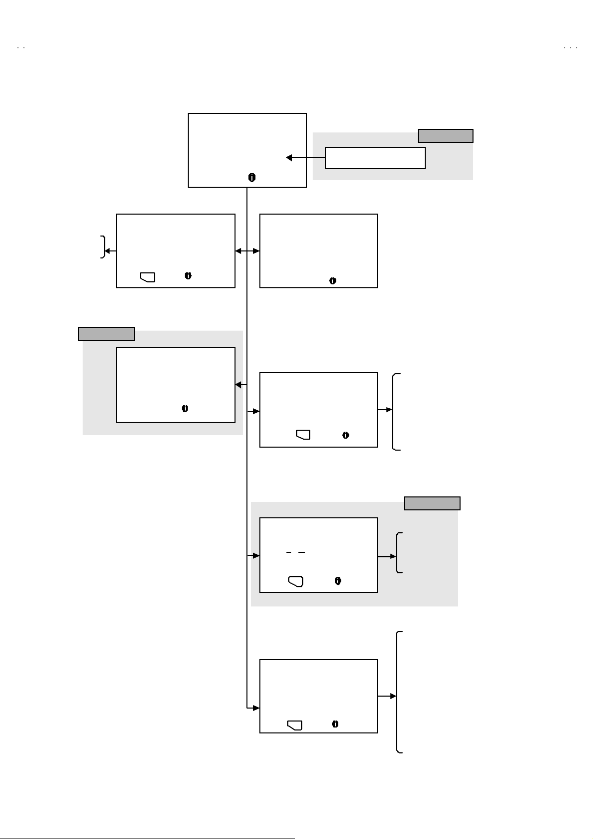
3. BASIC OPERATION OF SERVICE MENU
(1) How to enter SERVICE MENU
Press the INFORMATION key a nd the MUTING key of t he
REMO TE CONT RO L U NI T si mu lt an eou s ly, an d th e
SERVICE MENU screen of Fig. 1 will be displayed.
(2) Selection of S UB MENU SCREEN
Press one of keys 1~7 of the REMOTE CO NTROL UNIT
an d sel e c t th e S UB M ENU SCR EEN ( See Fi g. 3 ), fo rm th e
SERVICE MENU.
SERVICE MENU → SUB MENU
1. IF
2. V / C
3. AUDIO
4. DE F.
5. VSM PRESET
6. VP S
7. AUTO PROGRAM
SE RVICE M ENU
SERVICE MENU
1. IF 2. V/C
3. AUDIO 4. DEF
5. VS M PR ES ET 6 . VP S
7. AUTO PROGRAM (OFF)
1-7 : SELECT : EXIT
Fig.1
NEME OF REMOTE CONTOROL KEY
Names of ke
INFORMATION
MUTI NG
MENU
FUNCTIO N UP/DOWN
FUNCTIO N -/ +
Fig.2
ke
iiii
OK
▼
▼
▼
▼
No. 51952
15
Page 7
A
V28CT1EKS / AV28CT 1EKB
A
A
V28CT1EPS / AV28CT 1EPB
V28CT1EIS
SERVICE MENU
SERVICE MENU
1. IF 2. V/C
3. AUDIO 4. DEF
5. VSM PRESET 6. VPS
7. AUTO PROGRAM (OF F)
1-7 : SELECT : EXIT
7. AU TO PRO G RAM
7. AUTO PROGRAM (OF F)
7. AUTO PROGRAM (ON )
Do not adjust
COOL
NOR MAL
WARM
1. BR IGHT
2. CONT .
3. COL OU R
4. SHA RP
5. HU E
6. R DR IV E
7. B DR IV E
Do not adjust
5. VSM PRESET
VSM PRESET
NOR MAL
1. BR IGHT
- + : STORE : EXI T
OK
VPS = 0000H(- - -)
PD C 8 / 30 / 1 = 0 404 H
***
6. VPS
VPS
: EXI T
1.IF (VCO)
VCO (CW)
1. CUT OFF ( R)
- +
**
** ....**
**
****
****
TOO HIGH
ABOVE REFER ENCE
JUST REFERENCE
BEL OW R EFE RE NC E
TOO LOW
2. V /C
V/C
PAL
****
(G)
****
(B)
****
: ST ORE : EXI T
OK
MHz
: EXI T
1. CUT OFF
2. DR IVE
3. BR IGHT
4. CONT .
5. COL OU R
6. HU E
7. BLAC K OFFS ET
8. SHARP (Do not adjust)
9. PUR ITY (Do not adjust)
3. AU DIO
AU DIO
1. CONC L IMI T 0AH
C AD B I TS = 00 00000 0
: ST ORE : EXI T
OK
- +
SU B M ENU 4. D EF
DEF PANORAMIC
1. V- SHIFT
: ST ORE : EXI T
- +
OK
Fig. 3 SUB MENU SCREEN
***
(**)
Do not adjust
1. CONC LIM IT
2. A2 ID THR
3. ALC
4. BA SS
5. TREBLE
1. V-SHIFT
2. V-SIZE
3. SUB TITLE
4. H-C ENT
5. H-SI Z E
Hz
**
**
****
6. EW -PIN
7. TRAPEZ
8. EW.COR.L
9. EW.COR.H
10. V.S-COR
11 . V-L I N
12 . H -BL K-R
13 . H -BL K-L
14. V-EHT(Do not adjust)
15 . H -EHT ( Do no t ad jus t)
16 . EH T-G A IN (D o n o t ad jus t)
16
No. 51952
Page 8

A
V28CT1EKS / AV28CT 1EK
B
A
B
A
S
V28CT1EPS / AV28CT 1EP
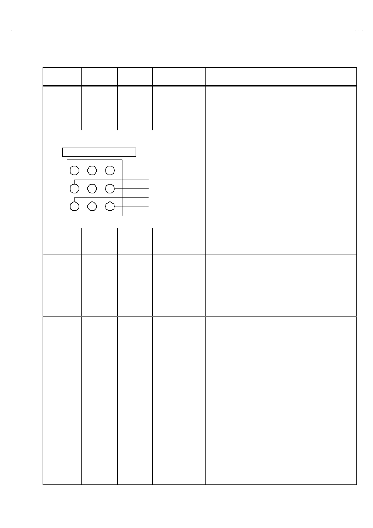
(3) Method of Setting
1) M eth od of Set ting 1. IF
[VCO]
① 1 Key ・・・・・・・ ・・・・・・・・・・・・・ ・・・・・ Select 1.IF.
② The VCO (CW) screen will be displayed in yellow when the AFC voltage is at a certain level and in blue when it is at other levels .
③ INFORMATION K ey ・・・・・・・ ・・・・・ Return t o th e SER VICE ME NU scr e en.
2) Meth od of s ett in g 2.V/C, 3.AUDIO, 4.DEF an d 5.VSM PRESET.
① 2~5 K ey・・・・・・・・・・・・・・・・・・・・ ・・ Select one from 2.V/C, 3.AUDIO, 4.DEF and 5 .VSM PRESET.
② FUNCTION UP / DOW N Key・・・・・ Se lect s etting i tems.
③ FUNCTION -/+ ・・・・・・・ ・・・・・・・・・・ Set (adjust) the setti ng valu es o f th e settin g it ems.
(U se the num ber keys of the REMOTE CONTROL UNI T for s etting of WHITE BALANC E.
For the s etti n g, ref er to ea ch it em c on cerned.)
④ MENU Key ・・・・・・・ ・・・・・・・・・・・・・ Memorize t he setting value.
(Bef or e st or ing t he s ett in g values i n me mo r y, do no t pr ess t he C H, TV, POWE R O N / OF F key -
if you d o, the valu es will not be stored in memory.)
⑤ INFORMATION K ey ・・・・・・・ ・・・・・ Ret urn t o th e SE RVICE M E NU sc ree n.
3) Meth od of s ett in g 6.VPS and 7 . AU T O PR O GR AM .
6.V PS ・・・・・・・ ・・・・・・・・・・・・・ ・・・・・・・ This mode displayed monitor of VPS syst ems. (Do not adjust)
7.AUT O PROGRAM・・・・・・・ ・・・・・・・・ W hen the MAI N POW ER is tur ne d on w it h the sta te of AU TO P RO GR AM ON, you ge t a m od e
that initializes every existing set value including language s elect ion. Because this mode is set
at th e factor y upo n co mpl eti on of the a djust ment , you need not t o use i t for servi ce.
(Do not adju st in this mode.)
V28CT1EI
(4) R ele ase o f SER V ICE M ENU
1) Af ter co mp leting th e setti ng , r etur n to t he SERVIC E ME NU , then ag ai n p r ess th e INFOR MATIO N ke y.
No. 51952
17
Page 9
A
V28CT1EKS / AV28CT 1EKB
A
A
SC
OCUS
V28CT1EPS / AV28CT 1EPB
V28CT1EIS
ADJUSTMENTS
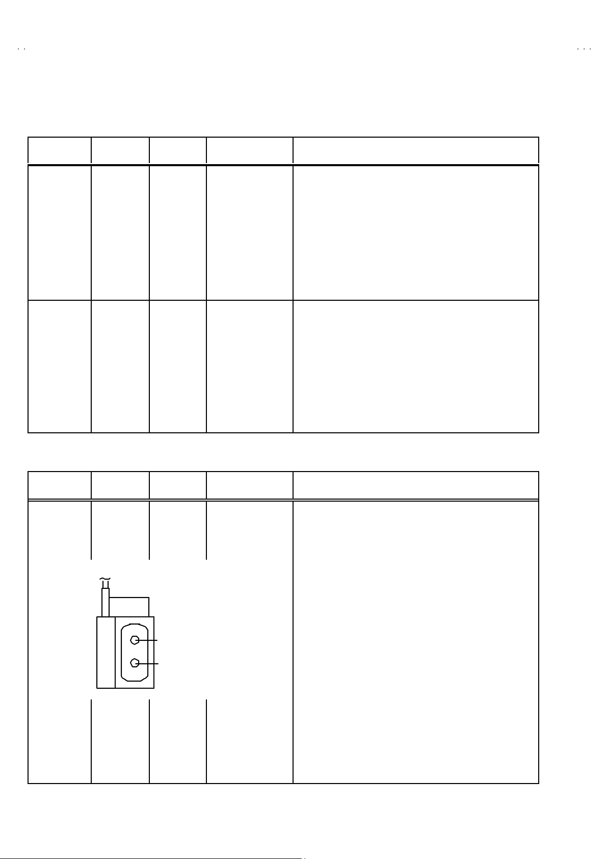
CHECK ITEM
Item
Check of B1
Power Supply
Measuring
instrume nt
Signal
generator
DC vo ltmeter
Remote
control unit
Test point Ad justment part Description
TP-91(B1)
TP-E(#### )
[X connector
on POWER
DE F PW B]
1. Recei ve a an y broa dcast.
2. Pu sh t he “ZOOM” k e y an d s elect the FULL mode .
3. Sele ct 2 .V/C f rom the SE RVICE M EN U.
4. Se lect 1. CUT OFF wit h Fu nctio n UP/ DOW N k ey.
5. Sh ow one ho riz on tal line w i th the 1 k ey.
6. Tur n the SCREEN VR, the whol e blac k scr een disp lay.
7. Con nect a D C vol tm eter t o TP- 9 1(B 1) a nd T P- E(#).
8. Mak e sure t hat the vol t age i s D C 14 4.5 ±2.0V.
9. Readjust the S CRE EN VR to ap pear th e hor izon tal li n e fai n tly,
an d cancel t he hor i zonta l lin e to p ress th e 2 key.
Check of High
Volt age
Signal
generator
DC volunteer
Remote
control unit
ADJUS TMENT OF FOCUS
Item
Ad justment of
FOCUS
Measuring
instrume nt
Signal
gener ator
CRT anode
Chassis GND
Test point Ad justment part Description
FOCUS VR
[In FBT]
1. Recei ve a an y broa dcast.
2. Pu sh t he “ZOOM” k e y an d s elect the FULL mode .
3. Sele ct 2 .V/C f rom the SE RVICE M EN U.
4. Se lect 1.CUT OFF wit h Fu nctio n UP/DOW N key.
5. Sh ow one h orizo ntal l in e with t he 1 key.
6. Tur n the SCREEN VR, the whol e blac k scr een disp lay.
7. Connect a DC voltmeter t o CRT ANODE and chassis GND.
8. Mak e sure t hat the vol t age i s D C 3 0.0kV .
9. Readjust t he SCREEN VR to appea r th e hor i zon tal lin e fain tly,
an d c onnec t the h orizo ntal l in e to press 2 key.
1. Receive a cross-hatch signal. S elect FULL m ode.
2. W hile watc hi ng th e s cr een , a djus t the FOCUS VR to m ake th e
ver ti cal and ho rizo ntal l ines as f in e a nd sha rp as possi b l e.
3. Make sure th at w hen the s c reen is darke ned , the lines r e ma i n
in good focus.
+1kV
-1.5kV
F
VR
REEN VR
18
No. 51952
Page 10
A
B
A
B
A
S
IF CIRCUIT ADJUSTMENT
Item
Ad justment of
VCO
Measuring
instrume nt
Remote
control unit
VCO( CW)
***.**
T OO HI GH
ABOVE REFERE NCE
JUS T REF ERENCE
BEL OW REFERE NCE
T OO LO W
: EXIT
Test point Ad justment part Description
MHz
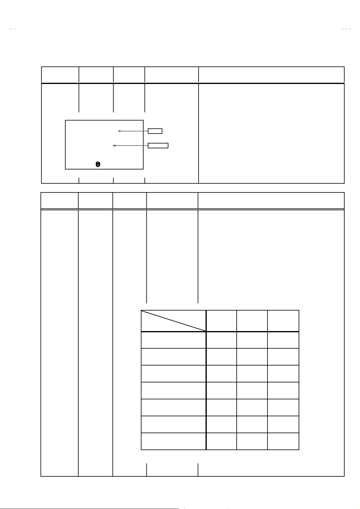
VSM PR ES ET AD JUS T SET TIN G
Item
Setting of
VS M PRESET
Measuring
instrume nt
Remote
control unit
Test point Ad justment part Description
fv
YELLOW
1. BR I G HT
2. CONT.
3. COLOUR
4. SHARP
5. HUE
6. R DRIVE
7. B DRIVE
V28CT1EKS / AV28CT 1EK
V28CT1EPS / AV28CT 1EP
V28CT1EI
"
U nd er n orma l c ondi ti ons, no ad just ment is r e quired .
1. Recei ve an y br oadc ast.
2. Select 1 .IF from t he SERVICE MENU.
3. Check th e charact ers co l our of the JU ST REFE REN CE
displayed to yellow.
1. Sele ct 5 .VSM P RESET from th e S ERVICE MENU.
2. Se lect C OOL with t he MEN U key of t he re mote con tr ol un it.
3. Ad ju st th e FUNC TION UP /D OW N and -/ + key t o bring t he s et
val u es of 1.B RIG HT ~ 7.B DR IVE to the val ues s h ow n in the
tabl e.
4. Press the ME NU key a nd mem or iz e th e s et va lue.
5. Respectively select the VSM PRESET mode for NORMAL and
WARM, an d m ake si milar a djust ment as i n 3 abo ve.
6. Press the ME NU key a nd mem or iz e th e s et va lue.
∗
Refe r to O PERATIN G INSTRUCTIONS for the PICTURE
MO DE .
VSM preset mode
Setting item
1. BRIGH T
SE TT ING VAL UE
2. CONT.
SE TT ING VAL UE
3. C OLO UR
SE TT ING VAL UE
4. SH ARP
SE TT ING VAL UE
5. H UE
SE TT ING VAL UE
6. R DRIVE
SE TT ING VAL UE
7. B D RIVE
SE TT ING VAL UE
COOL NORM AL WAR M
+0 +0 +0
+12 +10 +2
+6 +0 -2
+0 +0 -2
+0 +0 +0
-20 +0 +16
+23+0-13
SE TT ING VALUES OF VSM PRESE T
No. 51952
19
Page 11
A
V28CT1EKS / AV28CT 1EKB
A
A
ote Control Unit
V28CT1EPS / AV28CT 1EPB
V28CT1EIS
VIDEO / CHR OMA CIRCUIT ADJUSTMENT
The setting (adjustment) using the REMOTE CONTROL UNI T is made on the basis of the initial setting values.
The setting values which adj ust the screen to the optimum condition can be different from the initial setti ng val ues.
Colour sy stem
Setting Item
(Adjustment Item )
R -100 5. COLOUR +14 +0 +8
1. CUTOFF
2. DRIVE
3. BR IG HT +0
4. CONT. -10 9. PURITY (Do not adjust)
Item
Ad j ust men t
of WHITE
BALANCE
(Low Light)
Rem
H. LIN E O N
G -100
B - 100 R-Y +0
R
B+0
Measuring
instrume nt
Signal
gener ator
Remote
control unit
Initial set ting v al ue
+0
Test point Ad justment part Description
1.CUT OFF
SCREEN VR
[In FBT]
H. LIN E O F F
Setting item
6. HUE
7. BLACK OFFSET
(SECAM)
8. SH ARP
(Do not adjust)
(R)***
(G)
***
(B)***
B- Y +0
"
Se t th e PICTURE MODE to NORMAL.
1. Rec eive a bl ack a nd white sign al ( col o ur of f).
2. Sele ct 2 .V/C f rom the SE RVICE M EN U.
3. Select 1.CUT OFF with the FUNCTION UP/DOWN key.
4. Pu sh t he “ZOOM” k e y an d s elect the “PA NOR AM IC” mod e.
5. Sh ow one ho riz on tal line w i th the 1 k ey.
6. Gr ad ua lly turn the SC REEN VR fr om th e left en d to th e r i ght
direc ti o n to bring o ne of th e r ed , g r een or blue co l our f aint ly
visible.
7. Press 4 ~9 key, and br ing ou t the o the r 2 colours a nd make
on e h or izont al l ine vi sible i n white.
8. Turn th e SC R EEN VR a nd br i ng on e white horiz on tal lin e
faintly visible.
9. Press 2 ke y, tu rn of f 1. CUT OF F sc reen .
10 . Press the MENU key a nd mem oriz e th e s et va lue.
Initial set ting v al ue
PAL
-7
OFF
SE CAM
NT SC 3.5 8
NT SC 4.4 3
+2
20
1 2
R CU TOFF
4 5
R CU TOFF
7 8
G CUTOFF
G CUTOFF
3
B CUTOFF
6
B CUTOFF
9
No. 51952
Page 12
A
V28CT1EKS / AV28CT 1EK
B
A
B
A
S
)
)
V28CT1EPS / AV28CT 1EP
V28CT1EI
Item
Ad j ust men t
of WHITE
BALANCE
(High Light)
Measuring
instrume nt
Signal
gener ator
Remote
control unit
REMOTE CONTROL UNIT
1 2 3
4 5
7 8
Test point Ad justment part Description
6
9
2. DRIV E
DRIVE
(R)
DRIVE
(B)
DRIVE(R
DRIVE(B
(R)***
(B)***
▲
▲
▼
▼
"
The a dj ust me nt f or Lo w Light W H ITE BA LANC E sh ou l d b e
finish ed.
"
Se t th e PICTURE MODE to NORMAL.
1. Rec eive a bl ack a nd white sign al ( col o ur of f).
2. Sele ct 2 .V/C f rom the SE RVICE M EN U.
3. Se lect 2.DRIVE with th e FU NCTI ON UP/DOW N key.
4. Cha nge the sc reen col o ur to whi te wit h 4 key o r 7 key (D rive of
Red), 6 ke y or 9 key (Drive of Blu e) .
5. Press the MENU key, and memorize the set values.
Ad j ust men t
of
SUB BRIGHT
Ad j ust men t
of
SUB
CONTRAS T
Remote
control unit
Remote
control unit
3. BR IG HT 1. Recei ve an y br oadc ast.
2. Se le ct 2.V/C f rom the SE RVICE MEN U.
3. Select 3 .BRIGHT with th e FUN CTI ON UP/DOW N key.
4. Set the initial setting value with the FUNCTION -/+ key.
5. If th e brigh tn ess is no t th e be st wi th th e in i ti al se tting val ue ,
make fine adjustment until you get the bes t brightness.
6. Press the MENU key a nd mem oriz e th e s et va lue.
4.CO NT. 1. Recei ve an y br oadc ast.
2. Se le ct 2.V/C f rom the SE RVICE MEN U.
3. Select 4.CONT with the FUNCTION UP/DOWN key.
4. Set the initial setting value with the FUNCTION -/+ key.
5. If the contr ast is n ot the be st with the i niti al se tting va lue, ma ke
fine adjustment until you get the best contrast.
6. Press the MENU key a nd mem oriz e th e s et va lue.
No. 51952
21
Page 13

A
V28CT1EKS / AV28CT 1EKB
A
A
V28CT1EPS / AV28CT 1EPB
V28CT1EIS
Item
Ad j ust men t
of SUB
COLOURⅠⅠⅠⅠ
Measuring
instrume nt
Remote
control unit
Test point Ad justment part Description
5.COLO UR
(PAL~~~~NT S C)
PAL COLOUR (PAL COLOUR)
SE CA M C OLO UR
Only
AV28CT1E PS
AV28CT1E PB
[Method of adjustment without measuring instrument]
1. Rec eive PAL b road cast.
2. Sele ct 2 .V/C f rom the SE RVICE M EN U.
3. Se lect 5.COLOUR with the FUNCTIO N UP/DOW N key.
4. Se t th e in it ial sett ing value for PAL C OLO UR with the
FUNCTION - or + k ey.
5. If t he co lour i s no t the bes t with th e initial s et value, m ake
fine adjustment until you get the best colour.
6. Press the ME NU key a nd mem or iz e th e s et va lue.
(SECAM COLOUR)
1. Recei ve a SE CAM broa dcas t.
2. M ake fi n e adjustm e nt of SE C AM COLO UR i n the s ame
manner as for abo ve.
NTSC COLO UR
(NTSC 3.58 COL OUR)
1. Input a NTSC 3.58MHz COMPOSITE V IDEO sig nal fr om the
EXT t erminal.
2. Make s imil ar f in e ad justment of N TSC 3 .58 COLO UR i n th e
sam e mann er as f or a bo ve.
(NTSC 4.43 COL OUR)
1. When NTSC 3.58 is set, NTSC 4.43 will be automatically set at
the respective values.
22
No. 51952
Page 14

A
V28CT1EKS / AV28CT 1EK
B
A
B
A
S
(+)
(-)
0
(A)
V28CT1EPS / AV28CT 1EP
V28CT1EI
Item
Ad j ust men t
of SUB
COLOUR ⅡⅡⅡⅡ
Measuring
instrume nt
Signal
gener ator
Oscilloscope
Remote
control unit
Test point Ad justment part Description
TP-47B
TP-E(#### )
[CRT
SOCKET
PWB ]
5.COLO UR
(PAL~~~~NT S C)
PAL COLOUR (PAL COLOUR)
SE CA M C OLO UR
Only
AV28CT1E PS
AV28CT1E PB
[Method of adjustment using measuring instrument]
1. Rec eive a PAL full f ield co lour b ar si gn al (75% white ).
2. Sele ct 2 .V/C f rom the SE RVICE M EN U.
3. Se lect 5.COLO UR with the FUN CTI ON U P/DOW N key.
4. Se t th e i n it i al setti ng value of P AL COLO UR with t he
FUNCTION - or + k ey.
5. Con nect th e osc ill osc ope be twee n T P -4 7B and T P- E( #).
6. Adjust P AL C OL OUR an d b r in g the val ue of ( A) in th e
illustration to +6V.
7. Press the ME NU key a nd mem or iz e th e s etti n g value.
VOLTAGE (W -B)
+6V
(SECAM COLOUR)
1. Rec eive a SE CA M f ul l fie ld co lour b ar si gn al(75 % w hi te) .
2. Set the init ial setting value of SECAM COLOUR with the
FUNCTION - /+ ke y.
3. Adju st SE C AM C OLO UR an d br in g t he val ue of (A ) in t he
illustration to –5V.
4. Press the ME NU key a nd mem or iz e th e s etti n g value.
WCyMgB
NTSC COLO UR
VOLTAGE (W -B)
-5V
(NTSC 3.58 COLOUR)
1. Inp ut a NT SC 3.5 8MHz COMPOSI TE V IDE O s ign al (full field
colo ur bar with 75% w hit e) from th e EX T terminal.
2. Set th e initial setti ng value of NTSC 3.58 COLO UR with the
FUNCTION - /+ ke y.
3. Ad ju st NT SC 3.5 8 COL OU R and b ring th e val u e of (A) in the
illu strati on to 0V (Vo lt ag e d if fer en ce bet w een wh ite( W ) an d
blue(B).
4. Press the ME NU key a nd mem or iz e th e s etti n g value.
(NTSC 4.43 COLOUR)
1. When NTSC 3.58 is set, NTSC 4.43 will be automatically set at
the respective values.
No. 51952
23
Page 15

A
V28CT1EKS / AV28CT 1EKB
A
A
CyMg
(B)
(-)
(+)
V28CT1EPS / AV28CT 1EPB
V28CT1EIS
Item
Ad j ust men t
of
SUB HUEⅠⅠⅠⅠ
Measuring
instrume nt
Remote
control unit
Test point Ad justment part Description
6. HUE [Method of adjustment without measuring instrument]
NTSC 3.58 HUE [NTSC 3.58 HUE]
1. Inp ut a NT SC 3.5 8MHz COMPOSI TE V IDE O s ign al (f ull field
colo ur bar with 75% w hit e) from th e EX T terminal.
2. Sele ct 2 .V / C fr om t he SERVI CE MENU.
3. Select 6. HUE with the FUNCTION UP/DOWN key.
4. Se t the ini ti a l sett in g value of NT SC 3. 58 H UE w i th th e
FUNCTION - /+ ke y.
5. If you cannot get the best hue with the initial setting value,
make fine adjustment until you get the bes t hue.
6. Press the ME NU key a nd mem or iz e th e s et va lue.
NTSC 4.43 HUE [NTSC 4.43 HUE]
1. When NTSC 3.58 is set, NTSC 4.43 will be automatically set at
the respective values.
Ad j ust men t
of
SUB HUE
ⅡⅡⅡⅡ
Signal
gener ator
Oscilloscope
Remote
control unit
W
TP-47B
TP-E(#### )
[CRT
SOCKET
PWB]
B
6. HUE [Method of adjustment using measuring instrument]
NTSC 3.58 HUE [NTSC 3.58 HUE]
1. Inp ut a NT SC 3.5 8MHz COMPOSI TE V IDE O s ign al (f ull field
colo ur bar with 75% w hit e) from th e EX T terminal.
2. Sele ct 2 .V/C f rom the SE RVICE M EN U.
3. Select 6. HUE with the FUNCTION UP/DOWN key.
4. Se t the ini ti a l sett in g value of NT SC 3. 58 H UE w i th th e
FUNCTION - or + k ey.
5. Con nect th e osc ill osc ope be twee n T P -4 7B and T P- E(#)
6. Adjust N TSC 3. 58 H UE t o br i ng the val u e of (B) in the
illu strati on t o - 4 V ( vol tag e diff er enc e b et ween white (W) an d
magent a ( Mg ) ).
7. Press the MENU key and memoriz e the setting value
0
NTSC 4.43 HUE [NTSC 4.43 HUE]
1. W hen N TSC 3 .58 is set, N TSC 4.43 w ill b e aut omati ca lly se t at
the respective values.
24
No. 51952
Page 16

A
B
A
B
A
S
[Only AV28CT1EPS / AV28CT1EPB]
(c)
(d)
Item
of BLACK
OFF SET
(SECAM)ⅠⅠⅠⅠ
REMOTE CONTROL UNIT
Measuring
instrume nt
Remote
control unit
1 2 3
4
5
7
8
Test point Ad justment part Description
6
9
7. BL AC K
OFF SET
(R-Y) ***
(B-Y) ***
BLACK OFFSET ON
BLACK OFFSET
OFF
R-Y
▲
B- Y
▲
R-Y
▼
B- Y
▼
V28CT1EKS / AV28CT 1EK
V28CT1EPS / AV28CT 1EP
V28CT1EI
[Method of adjustment without measuring instrument]Ad j ust men t
1. Rec eive a SEC AM br oadc ast.
2. Sele ct 2 .V/C f rom SER VIC E MENU.
3. Se le ct 7 . BLACK O FFSET with th e FU NCTIO N UP/DOW N
key.
4. Se t the i n it i al se tting val u e for BLA CK OF FSET ( R- Y) an d ( B-
Y) wit h 4 and 7 or 6 and 9 k e ys of the remot e c ontrol.
5. If the pictur e i s not th e b est wit h the in it ial set ting value, m ak e
fin e ad j ustment un til yo u get t he be st p ict ure.
6. Pr ess the MENU key a nd memor i ze t he sett in g va l ue.
of BLACK
OFF SET
(SECAM)ⅡⅡⅡⅡ
[R-Y]
[B-Y]
Signal
gener ator
Oscilloscope
Remote
control unit
35 PI N (R -Y )
36 PI N (B -Y )
IC- 301 ON
MAIN PWB
(a) (b)
7. BL ACK
OFF SET
(R-Y) ***
(B-Y) ***
[Method of adjustment using measuring instrument]Ad j ust men t
1. R eceiv e a SECAM C OL OUR bar si gn al (f ul l field co l our b ar
75% white).
2. Select 2 .V /C fr om SERVICE ME NU.
3. Select 7.BL ACK OFFSET with the FUNCTION UP/DOW N
key.
4. C on nect th e os cillosc op e bet ween 35 pi n of IC-3 01 an d TP- E
(#).
5. By usi ng 4 and 7 keys of t he remote control, adjust the
BLACK OFFSET (R-Y) so that it becomes the waveform
ch anges f ro m (a ) t o ( b) shown in th e f igure.
6. C on nect th e osc ill osc ope be tween 36 pi n of IC-3 01 an d TP- E.
7. By usi ng 6 and 9 keys of the remote control, adjust the
BLACK OFFSET (B-Y) so that it becomes the waveform
ch anges f ro m (c) to (d) sh ow n i n th e figu re.
8. If the pi ctu re i s n ot th e best wit h th e adj u sted pi ctu re , m ake
fine adjustment until you get the best picture.
9. Pr ess the MENU key a nd memoriz e th e s etti n g value.
No. 51952
25
Page 17

A
V28CT1EKS / AV28CT 1EKB
A
A
V28CT1EPS / AV28CT 1EPB
V28CT1EIS
DEFLECTION CIRCUIT ADJUSTMENT
Th ere are 7 mo des of t h e adjus tme nt.
( 1 ) 50Hz mode ( ①①①① PANORAMIC ②②②②FULL ③③③③REGULAR ④④④④14:9 ZOOM ⑤⑤⑤⑤16:9 ZOOM ⑥⑥⑥⑥ 16:9 ZOOM SUB TITLE )
・・・・ ・
・・・・ ・
( 2 ) 60Hz mo de ( ea ch as pect mode )
"
The adjustment using the remote control unit is made on the basis of the initial setting val ues.
"
When the 50Hz PANORAMI C mode has been established, the setting of oth er modes will be done automatically.
However, if the picture quality has not been optimized, adjust each mode again, respectively.
" The setting v alues which adj ust the screen to the opti mum condition can be different from the initial setting values.
Ini tial setti ng v alue ( 1/2)
Setting item Ad justment name
1. V-SHIFTVertical center -10-1 +0+0+1+0+0+0
2. V- SIZ E Ve rt ic al he ig ht +8 - 2 +18 +15 +38 +37 +42 +40
3. SU BT ITL E SUBTIT LE B OTTOM Ver ti cal Line ar ity -8 + 0 +0 + 0 +0 + 0 +15 + 15
4. H-CENT Horizontal center -9 +5 +1 +1 +0 +0 +0 +0
5. H-S IZE H or izont al w idth +10 + 0 -12 -14 - 6 -6 -6 -6
6. EW-PIN Side pin correction -23 +0 -1 -1 -1 -1 -2 -1
7. TRAPEZ Tr ap ez oida l dis to rt ion c orrec tion +2 + 0 - 1 +0 - 1 + 0 +0 + 0
8. EW.COR.L CORNER PIN correction Low s ide +0 +0 +0 +0 +0 +0 +0 +0
9. EW.COR.H CORNER PIN correction High side +0 +0 +0 +0 +0 +0 +0 +0
10.V.S-CORVertical height correction +4+0+0+0+0+0+4+0
11.V-LIN Vertical Linearity -1+0+0+0+1+0+0+0
12.H-BLK-R BLANKING POSITION of Right side +0 +0 +123 +124 +0 +0 +0 +0
13.H-BLK-L BLANKING POSITION of Left side +0 +0 +36 +27 +0 +0 +0 +0
14 .V- EHT
(Do no t adjus t )
15 .H -E HT
(Do no t adjus t )
16 .EH T-GAIN
(Do no t adjus t )
V size correction level caused by EHT cha nge-4+0+0+0+0+0+0+0
H size correction level caus ed by EHT change -3 +0 +0 +0 +0 +0 +0 +0
Size c orrection gain caused by EHT change +0 +0 +0 +0 +0 +0 +0 +0
・・・・ ・・・・・ ・
De pending upon the kind of signals ( vertical freque ncy 50Hz / 60Hz ).
Initial set ting v al ue
PANORAMIC 14:9 ZOOM 16:9 Z OOM
50 Hz 60 Hz 50 Hz 60 Hz 50 Hz 60 Hz 50 Hz 60 Hz
16:9 ZOOM
SUB TITLE
Ini tial setti ng v alue ( 2/2)
Initial set ting v al ue
Setting item Ad justment name
1. V-SHIFT Vertic al center +0 +0 +0 +0
2. V- SIZ E Ve rt ic al height -6 -6 -3 -3
3. SU BT ITL E SUBTIT LE BOTTOM Verti cal Line ar i ty +0 +0 + 0 +0
4. H-CEN T H or izont al ce nte r + 0 +0 + 1 +1
5. H-S IZE H or i zont al w i dth -6 -6 -21 - 21
6. EW-PINSide pin correction +0+0+0+0
7. TRAPEZ Tr ap ezoidal disto rt i on c orr ec ti on +0 + 0 - 1 +0
8. EW .COR .L C OR NE R PIN co rrect ion Low s id e + 0 +0 + 0 +0
9. EW .COR .H C OR NE R PIN correc t ion Hig h side +0 + 0 +0 + 0
10 .V.S -COR Vertic al he ight c or r ection +0 + 0 +0 + 0
11 .V- LI N Ve rt ic al Lin eari ty +0 + 0 +0 + 0
12 .H -B LK -R BL ANKING P OSITI ON of Right s id e +0 + 0 + 123 + 124
13 .H -B LK -L BL AN KING P OSITI ON of Lef t si d e + 0 +0 +36 +27
14 .V- EHT
(Do no t adjus t )
15 .H -E HT
(Do no t adjus t )
16 .EH T-GAIN
(Do no t adjus t )
Vsize correction level caused by EHT change +0 +0 +0 +0
Hsiz e corr ect ion leve l c aused by EHT cha nge+0+0+0+0
Size c orre ction ga in ca used b y EHT chan ge + 0 +0 + 0 + 0
FULL REGULAR
50 Hz 60 Hz 50 Hz 60 Hz
26
No. 51952
Page 18

A
B
A
B
A
S
Item
Ad j ust men t
of
V-SHIF T
Measuring
instrume nt
Signal
gener ator
Remote
control unit
V28CT1EPS / AV28CT 1EP
V28CT1EKS / AV28CT 1EK
Test point Ad justment part Description
1. V- S HI FT [50 Hz PANORA MIC mode]
1. Rec eive a cir cle p att ern si g na l of vert ic al freq ue ncy 5 0Hz.
2. Se lect 4 .DEF f rom t he SER VI CE M EN U .
3. Se lect 1.V-SHIFT w ith t he FUNCTION UP/DOW N key.
4. Adjust V-S HIFT to make A = B.
5. Press the ME NU key a nd mem or iz e th e s et va lue.
****
For JK c hass is
A
B
Set all d ata exc ept for "PANORAM IC" to " 0".
Ad just V.CE NTE R of other asp ects w ith "P ANOR AM IC " mode
whil e al so ta king the ir p osi t io ns i n to c onsi d erat ion. If you want
to obt ain h oriz ont al l ines wi th l ess no is e o n th e s cr ee n, ad ju st
V.LIN instead of "PANORA MIC" mod e.
V28CT1EI
Ad j ust men t
of V-SIZE &
SUBTITLE
Scr e en
size
AS PE CT
MODE
SCREEN
TOP
SCREEN
BOTTOM
2.V-SI ZE
3.S UBTITLE
Screen size
Picture
size
10 0%
Picture size 100%
PANORAMIC 14 : 9 Z OOM 16 : 9 Z OOM
87 % 80% 70 % 70 % 92% 92 %
87 % 80 % 70 % 83 % 92 % 92 %
[ SCREEN S IZE ]
6. Rec eive a cros s -hatc h signal.
7. Select 2.V-SIZE and set the initial setting value.
8. Adjust V-SIZE and make sure that the vertical screen size of t he
pictu re si ze is in th e bel low t abl e.
9. Press the ME NU key a nd mem or iz e th e s et va lue.
10 . W hen ad jus t th e [S UB T IT LE ], se l ect “ 3 .SU BT IT L E” an d ad jus t
to un der p ar t o f pict ur e s ize.
11 . Inp ut a NTSC VIDEO si g na l (60Hz) f r om th e EXT t er minal, and
make sure t hat th e vert ic al scr een size i s in th e t able be low.
12 . Pr ess the MENU key and mem or ize the s et value.
16 : 9 Z OOM
SUB TITLE
FULL REGULAR
No. 51952
27
Page 19

A
V28CT1EPS / AV28CT 1EPB
A
A
V28CT1EKS / AV28CT 1EKB
V28CT1EIS
Item
Ad justment of
HORIZONTAL
CENTER
Ad j ust men t
of
HORIZONTAL
SIZ E
Measuring
instrume nt
CD
90 %
Test point Ad justment part Description
4.H-CENT. 13 . R eceiv e a c ircle p atter n s igna l.
14. Select 4.H-CENT and set the initial setting value.
15 . Ad ju st H- CE NT t o ma k e C =D .
16 . Press the ME NU key a nd mem or iz e th e s et va lue.
90 %
L
5. H-SIZ E 17. Receive a circle pattern signal.
18. Select 5.H-SIZE and set the initial sett ing value.
19 . Ad just H - SIZE and m ake sur e that t he ho riz o nta l sc reen size
20 . Press the ME NU key a nd mem or iz e th e s et va lue.
of th e pict ur e si ze is i n th e bel l ow t abl e .
AS PE CT
MODE
H SI Z E
Ad justment of
EW-PIN
* The nu m er ic of t he RE GU LA R an d 1 4:9 ZOO M m o des ar e
21. Input a NTSC VIDEO si gnal (6 0Hz) f rom the EXT term ina l,
22 . Press the ME NU key a nd mem or iz e th e s et va lue.
PANORAMIC 14:9 ZOOM 16 :9 ZOOM
PA L=95 %
NTSC=9 4%
Straight
L=495mm 92% 92% 92 % L=44 0mm
[ SCREEN S IZE ]
6.E W-PI N 23. Select 6.EW- PIN an d s et t he initial s etting value
24 . Ad just EW- PIN a nd ma ke t he 2nd .ve rt ic al lin es at th e lef t and
25 . Press the ME NU key a nd mem or iz e th e s et va lue.
sh own the length o f th e 90 % ho rizo nta l size posi ti on ( L ) as
sh own in the figu r e a bov e.
an d make s ure tha t the h orizo nt al s cr e en s ize of th e eac h
ASPECT mode is in the b elow table.
16:9 ZOOM
SUB TITLE
right ed ges of th e scr ee n str aig ht. Also mak e sure t hat the 3rd
vertical lines are straight.
FULL REGULAR
28
No. 51952
Page 20

A
V28CT1EPS / AV28CT 1EP
B
A
B
A
S
V28CT1EKS / AV28CT 1EK
V28CT1EI
Item
Ad j ust men t
of TRAPEZ
Ad justment of
EW. CORNER
L/H
Straight Straight
Measuring
instrume nt
Signal
gener ator
Remote
control unit
Signal
gener ator
Remote
control unit
Test point Ad justment part Description
7. TR APEZ 26 . Recei ve a c ross -h atch si gna l.
27. Select 7.TRAPEZ with the FUNCTION UP/ DOWN key.
28. Set the init ial setting value of TRAPEZ with the FUNCTION
- or + key.
Parallel
8.EW. COR. L
9.EW. COR. H
29 . Ad just TRAPE Z and b r ing t he VERT IC AL lines at the right
an d lef t edges o f the sc re en pa ralle l .
30 . Press the ME NU key a nd mem or iz e th e s et va lue.
31. Select 8.EW. COR. L with the FUNCTION UP / DOW N key.
32. Set the initial sett ing value of EW. COR. L with th e
FUNCTION – or + key.
33 . Ad just EW. C OR . L, and brin g the strai gh t li ne at the low
corner.
34. Select 9.EW. COR. H with the FUNCTION UP / DOWN key.
35. Set the init ial setting value of EW. COR. H with the
FUNCTION – or + key.
36 . Ad just EW. C OR . H , an d br i ng the str aigh t l i n e a t th e u pp er
corner.
37 . Press the ME NU key a nd mem or iz e th e s et va lue.
Ad j ust men t
Of
VERTICAL-S
CORRECTION
&
VERTICAL
LINEARITY
10. V- S.CR
11 . V- LIN
TOP
CENTER
BOT TOM
No. 51952
When the vertical linearity has been deteriorated remarkably,
•
perform the following steps.
38 . R ecei ve a cr oss- h atc h signa l.
39. Select 11.V-LIN with the FUNCTIO N UP / DOWN ke y.
40. Set the in itial setting value of 11.V-LIN wit h the FUNCTION
- / + key.
41. Select 10.V-S. COR with the FUNCTION UP / DOW N key.
42 . Set th e initial sett ing val ue o f 10.V-S. COR with the
FUNCTION
- / + key.
43. Adjust 11.V-LIN and 10.V-S.COR s o that t he sp aces of eac h
line on TOP, CENTER and BOTTOM be come unif orm.
NOTE : Do n ot adjust “PANORAMI C” & “16 : 9 Z OOM SU BTIT LE”
mode.
****
For JK chassis
On account of CRT (ITC), set V-S.COR excep t for
"PANOR AMIC " m ode to the minim um.
When ad ju sting "PA NO RAMIC" mode, sli gh tly exp an d th e
sp ac e at th e CENT ER wh ile taki ng the c ircul ar ity at th e
CENTER into consideration.
29
Page 21

A
V28CT1EPS / AV28CT 1EPB
A
A
V28CT1EKS / AV28CT 1EKB
V28CT1EIS
Item
Measuring
instrume nt
Test point Ad justment part Description
H. BLAN KING ADJUSTM ENT
Item
Ad justment of
HORIZONTAL
BL ANKING
Measuring
instrume nt
Test point Ad justment part Description
H H'
H. B LK
Capacitor
[On MAIN PWB]
At fi rst th e adj ustmen t in 50Hz -PANOR A MIC mo de sho uld be
d one, then the d at a for the o ther zoo m mode is correc t ed i n t he
resp ec ti ve val ue at t he same ti me. A nd c onf irm th e defl ec tion
adjustment initial s ett ing value in 60Hz ( TSC EXT mode )
PA NO RA MIC mo de . If th e ad ju stm en t i n 50 H z each zoo m
mode h as be en d on e a nd st ored, t he d ata f or th e same asp ect
modes in 60 Hz is corrected in the respective value. O nly t he
data for the oth er asp ect mode in 60Hz is c orrec ted for its elf .
1. R eceive the P AL c ircle p attern sig nal.
2. Select 4 .DEF f rom t he SER VI CE M ENU.
3. Select t he asp ect [ 14 :9 ZOO M] m ode.
4. Select 12.H-BLK-R with th e FUNCTION UP/ DOWN key a nd
ad just H - BLA NKIN G s o th at 92% of the pictu re on the r ig ht s ide
is di sp layed.
5. Select 13.H-BLK-L wit h the FUNCTION UP/DOWN key and
ad just H- BL AN KING so that 9 2% of th e pi ctu r e on th e l eft si de
is di sp layed.
6. Pres s the MENU key a nd memoriz e t he set val ue.
7. Select the asp ect [R EG ULAR ] mode.
8. Select 12.H-BLK-R with th e FUNCTION UP/ DOWN key a nd
ad just H’.B LAN KI NG s o th at 92% o f t he pic tur e o n the r igh t side
is di sp layed.
9. Select 13.H-BLK-L wit h the FUNCTION UP/DOWN key and
ad just H- BL AN KING so that 9 2% of th e pi ctu r e on th e l eft si de
is di sp layed.
10 . Press the ME NU key a nd m em or iz e th e s et va lue.
30
No. 51952
Page 22

A
V28CT1EPS / AV28CT 1EP
B
A
B
A
S
V28CT1EKS / AV28CT 1EK
V28CT1EI
AUDIO CIRCU IT ADJUSTMENT
"
Do not tou ch 3.AUDIO (1.CONC LIMIT, 2.A2 ID TH R, 3.A LC, 4. BASS, 5.TREB LE) of the SERVICE M ENU as it req uires no adjustment .
3. AUDIO
Setting item Variabl e range fixed value
1. CONC LI MIT(Do not adjust) 00 H ~ FFH 0AH
2. A2 ID THR(Do not adjust) 00 H ~ FFH 19H
3. AL C (Do not adjust)
4. BAS S (Do not adjust) -17 ~ +17 +0
5. TREBL E (Do not adjust) - 17 ~ +17 +0
20 MS EC 2S EC 4SEC 8S EC
No. 51952
31
Page 23

CIRCUIT DIAGRAMS MAIN PWB CIRCUIT DIAGRAMS
TU1_SW1
AFC_MAIN
R009
27
R008
0
C003
0.1
R427
*
R429
Q502
*
R505
220
R507
C507
0.01
C510
0.01
C511
0.01
C403
0.01
R514
4.7k
R411
0.5%
47k
R412
X
2200/16
QETM1CM-228
R428
*
100/16
X
220R506
1k
R010
*
MY
0.082
R007
100k
K003
C005
C509
C513
*
0.8V
3.8V
0.1V
11.7V
0V
1/50HFC512
0.6V
9.3V
3.8V
C405
LOCK
X
3.1V
3.6V
4.9V
9.1V
3.8V
0.01
32V
0.1
NCB21HK-104X
C007
C008
10/50
C009
0.1
CC
IC501
AN5441SA-W
DEF CONTROL
SDA
D.GN D
SCL
A.GND
H_FBP
PULSE
5V
TEST
NC
RAMP
HBLK
H
STONE
HBLK
EHT DC
L
VBLK
EHT AC
H
VBLK
CORNER
L
H_AGC
EW OUT
BLK OUT
V OUT
FEED
NECK
BACK
V FEED 12V
QFV71HJ-394Z
C514
0.01
YORCV
AGC
AGC
KEY
AV_LINK
SDA1
SCL1
Y305
*
SCL1
SDA1
100
R416
C407
0.82
C406
0.18
C407
C406
TF
TF
R415 X
D401
*
QFV71HJ-824Z
QFV71HJ-184Z
R519
5.6k
C516
0.01
R520
1.5k
C571
0.01
100
V_DRIVE
R517
4.7k
R518
6.8k
R516
2.2k
C408
*
0V
2.6V
V
11.9V
12V
7.4V
1.1V
2.4V
8V
R572
13k
0.6V
R573
820
2.8V
R571
4.6V
R414
100
0.5%
C515
11.9V
0.39
TF
SCL1
SDA1
L501
QQL244J-151Z
GND
GND
TV_VIDEO
SC_B
SC_B
SC_G
NC
V-BLK OUT
NC
SC_G
SC_R
SC_R
R405
C501
R406
X
SC_YS
SC_YS
22k
0V
GND
VAGC-filter
1.5V
100/16
GND
XC402
CORCV
GND
CORCV
18k
R404
4V 3.1V
V-NF
Vcc
C502
GND
YORCV
R403
1k
R402
10k
V-OUT
H-OUT
R501
0.01
QQL244K-4R7Z
H_DRIVE
TU001
*
OSD_HP
SW0
SW1
AFT
RF AGC
VIDEO OUT
GND
IFIN
TU2
(LOCK)
DATA
CLOCK
ADR
AGC
Q503
*
R509
22k
SIF
BV
NC
IF1
IF2
PB
MB
BT
C001
0.0022
R431
3.7V
0V
0V
0V
0V
3.8V
2.3V
4.9V
0V
32.4V
1.9V
4.2V
3.3V
3.6V
3.8V
*
RB100A-T2
D503
R001
1k
R002
*
R003
*
QQR0621-002Z
C010
100/16
0V
L001
QQL244K-5R6Z
C012
X
0
Y003
4.2V
R005
1k
R006
1k
C004
1000/16
1.1V
X
C011
K001
QQR0621-002Z
C006
10/50
R430
*
1000/16
R508
22k
R409
0
R511
0
R413
0.5%
NECK
TU1_SW0
K004
R011
5.6
1kR004
XK002
L002
QQL244K-270Z
C409
*
D402
*
C508
C404
0.01
22k
V_SAW
[1/2]
TO AV SEL & MSP PWB ASS'Y
GND
YORCV
AV_LINK
A.MUTE
GNDNCNC
YORCV
R309
2.2k
C505
1/50C401
0.0033
C506
0.1
3.3/50
C333
5.2
NC
2.5V
2.3V
V
V-ra mp
V-Sepa
Sync-IN
Sync-OUT
Curve
Correction
Coinsident Det
FBP-IN
Vdd(5V)
1.5V4.5V1.9V9V
2.6V
620
10k
100k
R502
R503
0.01
0.01
C503
C504
L301
4.7
120
1W OMR
R304
9VNCNC
R306
2.2k
R504
8.2k
5.1V 2.5V
AFC1-filter
SCL
C303
47/25
D301
MA3051/M/-X
R310
C304
GND
GND
Q301
*2
BUFFER
R401
10k
V Center
SDA
390
0.01
NC
R305
5.6k
2.8V
SDEMO-adj
GND
0V2.8V3.3V5.2V
390
R311
NC
R312
GND
GND
CORCV
R307
1k
R308
470
C301
0.1
C302
2.1V
Video-IN
Composite
B-OUT
2.5V
100
R313
5V
0.082
100
5V
R314
5.6k
BUFFER
C309
68p
2.3V
APL
G-OUT
2.5V
SDA2
R317
SDA2
Q302
4.7/50
100
AV28CT1EKS / AV28CT1EKB
AV28CT1EPS / AV28CT1EPB
GND
SCL2
SCL2
*2
0.01
C310
CH
C312
0V 4.8V
GND
R-OUT
2.5V
C313
100/16
R321
D302
*3
12V
12V
R690
27
1W
OMR
L302
4.7
QQL244K-4R7Z
C306
0.01
C307
470/16
16.2MHz
QAX0305-001Z
4.1V
Y/C-Vcc(5V)
Chroma IN
GND
ABL
C314
1k
ABL
SIFAMTV_AUDIO
GND
L_MONO
9.4V
C672
0.1
C305
100/16
C308
12p
CH
R316
220k
X301
2.4V
2.4V
Black
16MHZXtal
RGB-Vcc(9V)
Digital R-IN
1k
R318
0.01
C315
10/50
GND
GND
IC607
BA05T
Stretch
0V
5.2V
GND
Vdd
Fsc
G-IN
Digital
LC301
C311
R3201kR319
GND
MSP_RES
10/50
2.3V
B-IN
Digital
1k
NC
MSP_RESET
5VANC
4.9V
C671
100/16
1.7V 1.7V
Y-OUT
B-Y OUT
Ys
Digital
1k
R3291kR328
22k
4.7k
R330
R346
5V
GND
100/16
*R327
R-Y OUT
Analog YS/YM
1/50C324
D303
*3
100/16
C329
47/25
C319
0.1C321
2.3V
R-Y IN
R-IN
Analog
C328
R332
2.2k
R_OUT
L_OUT
1/50C325
CN006
QGB1505J1-50
C320
0.01
0.1C3221/50C326
2.3V
B-Y IN
G-IN
Analog
R331
33k
AV28CT1EIS
SECAM Trap SW
Q308
*
R335
27k
1/50C331
0.1
2.9
V
Filter
VM OUT
APC
D304
2.4V2.4V2.4
B
R
TC4053BP/N/
RGB.SW
C330
4.2V
*3
IC302
*
C332
0.01
2.3V
V
B1
Q309
BUFFER
9V
R336
X
IC301
TB1227CN
V/C DEF
0V
0V
2.3
V
B0
*
R337
X
L306
K307
QQR0621-002Z
L305
C323
4.7
2.2
0V
V
Y-IN
GND
Fsc
B-IN
Analog
Color
LimiterNCC/V SECAM/OTHERS
2.4V4.5V4.5V4.5V0V0.5V0V0V0V9V6.3V
C327
4.7/50
R340
33k
R341
33k
R333
2.2k
4.9
V
VDD
R1R0G1GG0
2.4V2.3V2.4V2.4V2.3V0V 0V 0V
X
3.5V
Ys
Ys
4.9V4.9
INH
Q312
4.9V
Q311
*5
*2
SW
SW
V
B
VEE
LC301
CE42142-222Z
K307
QQR0621-002Z
L305
QQL244K-4R7Z
R342
1.5k
0V
0V
R344
470
0V
R343
2.7k
R345
1K
4.9
V
C
VSS
SC_YS
SC_B
SC_G
SC_R
AV28CT1EKS / AV28CT1EKB
AV28CT1EPS / AV28CT1EPB
AV28CT1EIS
R608
8.2k
R609
8.2k
R611
R610
10K
10K
Y617
X
Y618
0
R417
R418
R420
*
18k
7.6V
8.2V
Q402
R419
*1
*
SW
0V
7.6V
Q401
22k
*5
SW
0V
STB
Y606
C623
220/16
C622
220/16
D602
X
*3
MSP_RES
MSP_RES
Q604
POWER ON/OFF DET
4.4V
R638
47k
4.9V
R633
27k
SP_R
A.GND
CENT.VCC
SCL2
SCL2
SDA2
SDA2
SP_L
AUDIO AMPLA4446IC601
LIN
DC(MUTE)
LNF
POGND
LBS
LOUT
VCC
ROUT
RBS
POGND
RNF
PRGND
RIN
0V
R643
X
C630
X
C640
220p
5%
0
0R003
(1/2)
0.1 TF
0.1TF
4.7
1/2W
47/25
C637
C638
R645
C631
R644
0V
0Y605
0Y604
560
C639
10/50
NOTE
X
:
OPTION(NON MOUNT)
BW
:
IM-BW
0
:
NRSA02J-0R0X
*1
:
2SC2412K/QR/-X
:
*2
2SA1037AK/QR/-X
*3
:
MA111-X
*4
:
MA3100/M/-X
*5
:
DTC124EKA-X
*6
:
DTA124EKA-X
*7
:
2SC1740S/QR/-T
*8
:
2SA933AS/QR/-T
0V 0V 0V
21.5V1.1V 0V 20.3V11.2V21.5V11.1V20.3
C605
10/50
C606
220/25
N
560
X
R635
R641
C626
100/25
N
C625
X
C624
47/25
C632
220p
C633
5%
*2Q609
0.2V
MUTING
D608
*2
*3
0V
D624
R639
10k
D625
0.6V
D612
R648
*3
*3
100k
Q610
C641
22/50
DTC323TK-X
MUTING
*3
D604
0.1TF
X
C634
0.1TF
R642
4.7
1/2W
0V
-2V
Q612
0V
DTC323TK-X
MUTING
0V
DIFFERENCE LIST
R327
L306
C330
Q308*5X
TU001
CN012 XX
R690
R002
R009
R010
R415
C408
Y305 0
R009
R010
R418
R419
QETM1EM-228C627
2200/25
1000/25
C635
SJK1916A-U2
X
X
QAU0189
-2
27
X
X
X
X
5.6k 5.6k
0.015
X
X
6.8k
5.6k
C636
C629
100/25
N
1000/25
SJK1716A-U2
QQL244K
39p CH
QAU0188
0.015
N
4700
-330Z
-2
100K
100K
100k
100k
6.8k
5.6k
V
XD605
27
0
MAIN PWB
SJK-1716A-U2(AV28CT1EPS/EPB/EIS)
SJK-1916A-U2(AV28CT1EKS/EKB)
OSD_HP
SYNC
OSD_VP
5V
5V
HBLK_L
HBLK_R
OSD_VP
OSD_VP
SYNC
SYNC
REG
OSD_R
SDA1
SCL1
REG
SCL1
SDA1
OSD_R
OSD_G
OSD_G
OSD_B
OSD_B
OSD_YS
OSD_YS
TXT_R
TXT_R
TXT_G
TXT_G
TXT_B
TXT_B
TXT_YS
TXT_YS
S_COR
AMP_MUTE
A_MUTE
EXT1/OTH
S_COR
A_MUTE
EXT1/OTH
AMP_MUTE
12V
9V
12V
SCL1
SDA1
CN008
QGA2501C5-08Z
B
R
G
VM
12V
12V
GND
TO CRT SKT PWB ASS'Y
GND
OSD_B
OSD_REWOSD_YS
OSD_G
TXT_YS
No.51952 No.51952
TXT_R
TXT_G
QGB1506L1-16
2-5 2-6
EXT1/OTH
CN003
TXT_B
ABL
OSD_HP
V_DRIVE
NC
ABL
HFB
GND
GND
GND
V.DRIVE
TO POW DEF PB ASSY
V_SAW
H_DRIVE
NECK
EW
REG
S_COR
EW
GND
GND
GND
NECK
V.S AW
S.COR
H.DRIVE
REG/OTH
A_MUTE
AMP_MUTE
Page 24

MAIN PWB CIRCUIT DIAGRAM [2/2]
AV28CT1EKS/AV28CT1EKB
AV28CT1EPS/AV28CT1EPB
AV28CT1EIS
AV28CT1EKS/AV28CT1EKB
AV28CT1EPS/AV28CT1EPB
AV28CT1EIS
IC871
ET417
NCB21EK-104X
DATA SLICER
0.1
C871
TSIG
0V
2.7V
SCAN_0
SSIG
C872
3V
0.022
0.9V
C873
X871
13.875MHz
BUFFER
R706
22k
Q871
*2
0V
C877
0.1
NCB21EK-104X
L871
4.7
QQL244K-4R7Z
R703
27k
4.6
V
D702
*3
R707
10k
CE41257-001Z
C874
15p
C878
0.001
R873
2.2k
2.5V3.2V
0V
C880
470/10
Q703
*1
4.9V
R710
5V
10k
Q702
*1
DIFFERENCE LIST
SJK-
SJK-
1916A-U2
C879
R743
R744
C832
X
R841
R835
X
X
R834
Q832
X
X
BUFFER
N
C831
X
Q833
X
AMP
R837XR842
X
C835
R839
X
X
R838
X
R840
X
C833
X
C834
X
Q834
X
AMP
Q835
X
BUFFER
C836
X
R843
X
R844
X
Q836
R845
X
X
SW
1712A-U2
18p220p
100X
X
100
C701
1
NCF21CZ-105X
R701
220
R705
1k
D701
MA3068/M/-X
Q701
*1
-0.5V
R704
47k
XR850
C837
X
R846
X
R847
X
R848
X
IC831
X
AUTO PANORAMA IC
C838
X
R851
R849
X
X
12V
5V
X831
X
IC832
X
RESET
C839
X
GND
VDD
OUT
R852
X
D831
X
AA_SDA
XR853
XR854
XR855
XR856
R857
X
Q837
X
INV
9V
AA_50/60
R858
X
R859
X
AA_FRQ
AA_SCL
VP
C879
R874
2.7k
0V
CH
R871
1k
*CH
R708
10k
Q704
*1
220p
C875
15p
C876
0.001
R872
2.2k
C881
0.1
NCB21EK-104X
7V
2.4V
R7091kR714
10k
0V
2.1V
2.9V
4.9V
1.3V
0V
1.3V
4.9V
4.5V
SYNC
CSIG
0V
DGND
0.1V
OSCOUT
DGND
TDATA
TSTAPLB
1k
WIND
TCLK
NCB21EK-104X
4.8V
DVcc
2.1V
0V
0.1V
0.1V
0V
C702
X
N
D703
X
AGND
OSC1
OSC2
AVcc
CREF
AGND
BIAS
Q705
*2
R713
0V
R875
100k
C884
0.1
R715
X
2.4V
C703
47/25
47/25
QQL244K-3R3Z
K872
3.3
C883
0.01
5V REG/RESET
IN
cd GND
5.7
V
C706
0.1
NCB21EK-104X
100/10
C882
NCB21EK-104X
BUFFER
4.9V
2.5V
L78LR05E-MAIC703
RESET
4.9
0V
V
C707
0.47/50
MA3036-X
X701
CST8.00MTW
or
QAX0667-001Z
L701
4.7
C704
0.1
NCB21EK-104X
C705
D704
*3
QQL244K-3R9Z
L701
QQL244K-4R7Z
OUT
47/25
D705
0V 0V2V
GND
5V
4.9V
L702
3.1V
4.9V
C885
0.1
3.1V
R876
1k
C708
X'TAL
OSC1
2.6V
C709
9p
CH
IC872
TELETEXT DECODERS
4.9V
TEST5
SYNC
VIDEO
0V
DVcc
4.9V
RSTB
2.1V
CLKIN
0V
DGND
0V
TEST1
4.9V
TEST4
0.1V
TDATA
0.1V
TCLK
4.5V
CSB
Q872
*1
MUTE
0V
IC702
AT24C1628CT1EP
MEMORY
SDA1
SCL1
R717
100k
R716
1k
C725
0.001
4.9V
2V
GND
X'TAL
PROTECT
BBE ON/OFF
RESET
OSC2
2.7V
4.9V 4.9V
*3D706
3.9
R718
6.8k
L702
R719
6.8k
C710
9p
CH
ET206
RGBSET
GREEN
BLANK
TEST3
GND A2 A1 A0
SDA3
SCL3
4.9
4.9V4.9
V
SDA3
SCL3
R767
10k
H/P DET
MSP.
TEXT RESET
A.MUTING
0V 0V
FLAG1
FLAG2
REF
AGND
RED
AVcc
BLUE
SDA
SCL
WINDGND
RC
VDD
V
2.2V
4.9V
5V
AGC
AMP MUTING
POWER
3.7V
0V
1.3V
1.7V
0V
0V
0V
4.9V
0V
0V
3.3V
3.5V
4.9V
ON/OFF
4.7k
R724
SDA2
3.2V
Y871
0
C886
0.01
R877
39k
C711
NCB21EK-104X
4.7kR720
0V
NC
AV_LINKOUT
SDA1
SDA2
3.2V
4.7k
R725
220R730
220R729
SDA1
R878
1.5k
R883
1k
0.1
BUS_FREE
C712
DOLBY IFOK
2
DOLBY CLOCK
4.7k
R727
SCL2
MAIN PWB
SJK-1716A-U2(AV28CT1EPS/EPB/EIS)
SJK-1916A-U2(AV28CT1EKS/EKB)
C887
R880
10/50
R881
330
4.7kR722
150p CH
0V
I C BUS FREE
SCL2
3.9V
220R731
1.5k
1.5kR879
REMOCON
XR736
AA_50/60
330R740
4.7V
0V
AA_50/60
REMOCON
DOLBY DATYSSCL1
3.4V
4.7k
R745
SCL1
R882
330
R884
330
AA_SDA
0V
AA_SDA
DOLBY IFCS
220R748
C889
10/50
D707
XR739
AA_SCL
XR741
MICRO
4.9V 0V
C888
10/50
*3D708
*3
X
R737
AA_FRQ
0V 0V
AA_SCL
AA_FRQ
COMPUTER
TU1_SW1
EXT/OTH
*R743
3.5V 2.4V
S_COR
LR_CENT
SDA3
TU1_SW0
*R744
4.9V4.9V
4.7k
R747
SDA3
TXT_R
TXT_G
TXT_B
TXT_YS
C718
0.033
KEY1
KEY2
1k
R753
10kR756
4.8V
4.8V
N/S
KEY1
CANCEL
AFC MAIN
ROTAT I O N
NS CEN/OTH
SCL3
4.9V
4.7k
R759
220R749
220R764
SCL3
R806
220R750
180k
220R751
220R752
220R765
220R766
BUS_FREE
KEY2
R755
R763
1kR780
ECO
1k
5.1V
ECO IN
REG
0V 4.5V
10k
0V0V0V
2V
LOCK
M37280MK-221SP
H_BLK_L
H_BLK_R
1V0V0V
33k
2.2k
R802
R801
33k
R774
R775
1/50
C716
C717
R805
(2/2)
VP
4.6V
VPULS
AV_LINKIN
IC701
0V
R771
2.7k
R770
2.2k
*3
D710
2.2k
R777
33k
1/50
3.3k
SYNC
AFC_MAIN
CN001
QGF1220C2-19
GND
SP_L
SP_R
C668
0.1
C668
NCB21EK-104X
GND
KEY2
KEY1
STB_5V
GND
GND
REMOCON
ECO
P_ON/OFF
NC
12V
SP_L
SP_L
SP_R
SP_R
AUDIO GND
AUDIO GND
AUDIO GND
TO CONTROL PB ASSY
KEY2
KEY1
STB_5V
Q708
*2
INV
R784
4.9V
R785
22k
22k
0.2V
4.5V
C722
R787
X
3.3k
Q709
*1
INV
R788
2.7k
D709
X
Q710
4V
4V
HPULS
RGB
0V
2.2k
R772
2.2k
R773
2.2k
R779
2.2k
R778
R789
*1
47k
INV
0V
C723
X
R790
6.8k
REMOCON
ECO
LOCK
S_COR
R786
47k
0.4V
OSD_VP
C726
X
CH
OSD_HP
NOTE
X
:
OPTION(NON MOUNT)
BW
:
IM-BW
:
NRSA02J-0R0X
0
*1
:
2SC2412K/QR/-X
:
*2
2SA1037AK/QR/-X
*3
:
MA111-X
*4
:
MA3100/M/-X
*5
:
DTC124EKA-X
*6
:
DTA124EKA-X
*7
:
2SC1740S/QR/-T
*8
:
2SA933AS/QR/-T
A.GND
AFC_MAIN
SYNC
TXT_YS
TXT_B
TXT_G
TXT_R
TXT_YS
TXT_B
TXT_G
TXT_R
SP_R
SP_L
SP_L
SP_R
S_COR
LOCK
OSD_HP
LOCK
S_COR
OSD_VP
OSD_HP
OSD_VP
SYNC
AFC_MAIN
SCL2
SDA2
SCL1
SDA1
9V
5V5V5V
CENT.VCC
CN005
QGB1506L1-16
GND
GND
GND
P_ON/OFF
NCNCNC
GND
AUDIO GND
AUDIO GND
CENT.VCC
CENT.VCC
TO POW DEF PB ASSY
NC
GND
PROTECT
32V
GND
GND
CN004
QGB1506L1-16
No.51952
9V
12V
12V
STB
GND
3.3V
GND
GND
GND
GND
5V
9V
32V
12V
YORCV
AV_LINK
STB
AGC
SCL2
SCL1
SDA2
SDA1
A_MUTE
MSP_RES
AMP_MUTE
TU1_SW0
TU1_SW1
EXT1/OTH
2-7 2-8
SCL1
SCL3
SDA1
D_GND
CN0C2
CH41169-006Y
SDA3
CN0C1
BUS_FREE
X
REG
OSD_B
OSD_R
OSD_G
HBLK_L
HBLK_R
OSD_YS
No.51952
Page 25

POWER & DEF. PWB CIRCUIT DIAGRAM
AV28CT1EKS / AV28CT1EKB
AV28CT1EPS / AV28CT1EPB
AV28CT1EIS
AV28CT1EKS / AV28CT1EKB
AV28CT1EPS / AV28CT1EPB
AV28CT1EIS
!
L01 DEG COIL
QQW0102-001
CNDE2
CNDEG
CH42145-802T
CN00W
AC
AC
X
X
Y908
*
Y902
X
NOTE
*1:
*2:
*3:
: : X
C901
X
!
R902
QRZ0123-121
120 7W UNFR
Y905
X
Y901
X
R903
3.9
10W UNF R
QRF104K-3R9
STR-F6667B/F7
REFERENCE LIST (*PARTS)
2SC1740S/QR/-T
2SA933AS/QR/-T
1SS133-T2
BUS WIRE
NON MOUNT
(OPEN)
!
TH901
QAD0120-9R0
Y907
BW
Y906
X
! LF901
QQR1095-001
QQR0659-004
! L903
XY903
XY904
GND
IC901
DRAIN
SOURCE
OCP/FB
MTZJ15B-T2
SJK2512A-H3
QFZ0200
C521
-722
QRL039J
R504
-821
QQR1137
L522
-4
QFZ0197
C529
-104
QFV71HJ
C561
-154Z
QRE121J
R465
-103Y
R468
BW
L551 X
QRL039J
R505
-681
QFZ0197
C532
-374
R591
12k
L901
QQL402K-100
L902
QQL402K-100
C902
C903
CEHT12N-026PSHS001
0V
10
.1V
VIN
333V
0V
1.2V
D911
D3SBA60
!
X
!
X
!
QCZ9054-472
C914
X
QRM059J-R15
*
R464
C543
R414
R415
D963
C528
C542
R406
R467
C904
0.0047
AC250V
K903
BWD910
SJK2512A-H3
QRE121J
-682Y
QFZ0197
-204
QRE121J
-3R9Y
QRX01GJ
-1R8
3.9B-T2
QFZ0197
-683
QFZ0197
-824
QRL039J
-120
D901
MTZJ
X
R910
1/2W
R911
10k
!
AC250V
QCZ9054-472
3W OMF
QRG039J-683
680
0.15
C906
0.0047
R909
68k
D908
BW
D912
BW
!
C905
0.0047
QCZ9054-472
QEZ0199-227
C907
220/385
MTZJ27B-T2
C913
47/50
R912
2.2 2W OMF
QRT029J-2R2
Y909
BW
R917
X
2W OMF
Q901
X
C917
X
TF
R918
3.3k
AC250V
R906
D913
D909
*3
BW
1/2W
D906
BW
D907
R904
X
470k
1/2W
R905
470k
1/2W
QRL039J-823
.01/500V
QCB32HK-103
D902
BYD33M-T3
D903
X
K904
QQR0679-001
C911
X
C912
470p
R916
X
100/50
C918
680p
C919
X
QRZ9046-825Z
R907
3W OMF
82k
C908
C910
.001/2KV
QCZ0122-102
QCZ0122-391
K901
QQR0679-001
XK902
C915
X
D904
BYD33D-T3
C916
D905
BYD33D-T3
R914
2.7k 1/2W
R915
X
PC123FY2
VOLTAGE FEEDBACK
!
R991
8.2M 1/2W
R908
3W OMF
QRL039J-823
R908
82k
C909
390p/2kV
C909
QRZ9017-100
!!R913
10 1/4W
FR
PC901
RY931
QSK0099-001
QQT0303-001
QQS0099-001
3.5V
3.5V
CN005
QGB1506M1-16
R931
BW
Q931
C931
D931
*3
1N4003-T2
1N4003-T2
!
!
ISOLATEDLIVE
QQR0872-001Y
Y951
X
R951
3W OMF
3.5V
3.5V
D936
D935
1N4003-T2
D937
D938
1N4003-T2
C992
470 AC250V
QCZ9079-471
C991
0.0033 AC250V
QCZ9079-332
K951
QCB32HK-391Z
K952
QQR0621-002Z
QCB32HK-391Z
K953
QQR0621-002Z
CEHT11B-002Q
Y953
HS955
BW
K954
QQR0621-002Z
X
R952
X
T921
X!C993
T901
0.1V
X
0V
!
CP957
ICP-N5-Y
QCZ0122-561
C953
D953
BYW95B-20
C955
D954
BYW95B-20
*1
0.7V
R932
C934
10/50
CP
D951
RU4B-F1
QEZ0203-227
C951
560p/2kV
IC PROTECT
CP951
BW
CP
2200/25
QTMM1EM-228
CP952
!
ICP-N50-Y
CP
IC PROTECT
C956
2200/16
QTMM1CM-228
C958
QCB32HK-391Z
!CPCP953
ICP-N75-Y
D955
FMX-G12S
QETM1VM-228
R933
1k
X
2SC2655/Y/-T
R939
C935
220/25
220/160
X
C952
C954
C959
2200/35
C933
10/50
5.4V
C964
0.68
C932
D932
5V
TF
X
BW
R934
Q933
10.4V
D934
MTZJ6.2B-T2
D939
*3
R940
39
1/2W
QQLZ026-460
C957
X
D933
BW
X
R937
BW
R938
1k
1/2W
L951
1SR35-400A-T2
D958
D963
*
R964
1k
1/2W
C979
0.1
TF
46
XY952
141.3V
12.6V
5V5V5V
!
CP956
ICP-N10-Y
Y954
0V
GND
CP
BW
IN
COM
E
GND
POWER_ON/OFF
R936
10k
14.9V
C968
0.1
CC
MTZJ7.5C-T2
R976
C971
10
0.1
2W OMF
QRL029J-100
C974
0.1
CC
X
R977
3.3V REG
C977
R953
X
IC951
SE140N
ERROR AMP.
GND*GND
CC
AUDIO_B
10.4V
4.7V
MTZJ33B-T2
R978
D985
12.9V
IC953
7.1V
IC955
X
NCNCAUDIO_B
D964
9V REG
BA17809T
X
AUDIO_E
Q932
4.1V
R935
47k
X
12V REGIC952
BA12T
5V REGIC954
BA05T
*1
0V
2W OMF
12V
X 2W OMFR979
NCNCAUDIO_E
QQL26AK-820Z
C969
470/16
XHS962
QEHR1CM-477Z
9V
C972
220/16
4.9
V
C975
220/10
CEHT11B-002QHS964
C978
R967
22k
QRL039J-223
3W OMF
L952
QEHR1CM-107Z
82
100/16
L953
5.6
QQL26AM-5R6Z
C973
47/25
L954
QQL26AM-5R6Z
5.6
C976
47/25
X
C970
AUDIO_E
AUDIO_B
5V
STB
-13V
D401
MTZJ75-T2
X
QFLC2AJ-683Z
R409
10k
1.4V
R501
BW
REGULAR
S_COR
C403
C405
0.0047
R410
1k
R413
1/2W
QQR0621-002Z
R417
1/2W
G
R502
2.2k
Q501
BSN304-T
H.DRIVE
32V
B1
V_DRIVE
12V
D981
9V
5V
D984
3.3V
AUDIO_B
AUDIO_E
V_SAW
*3
X
C409
*3D982
EW
*3D983
H_DRIVE
POWER & DEF. PWB
CN004
QGB1506M1-16
NECK
R492
68k
R493
220k
CEHT12N-014QS
HS003
IC401
THERMAL
PROTECTION
-Vcc Vcc
13
1.9V
0.2V
.2V
C402
1000/35
QETM1VM-108
C406
MY
QCZ0337-180Z
R407
BW
R406
*
C407
0.001
MY
R414
*
X
R415
*
K401
C410
R416
0.33QFV71HJ-334Z
82
0.33QFV71HJ-334Z C408
1
C411
MY
.056/100
680p/500
QCB32HK-681Z
C502
93V
D
C501
X
S
R503
1.5k
1/2W
GND
D491
BYD33D-T3
C491
1/50
LA7841VERT OUT
PUMPUP
1.9V 13
.4V
1W OMF
MY
T501
CE42034-002
C503
1/160
QEHR2CM-105Z
R504
3W OMF
*
R505
3W OMF
*
R548
2.2k
1/2W
0V
GND
GND
PROTECTOR
32V
STB
STB
32V
-11.3V
C401
R403
220/35
1.2k
4W
QEHR1VM-227Z
D402
1N4003-T2
!
D492
R494
4.7
1/4W
QRZ9017-4R7
R461
2.8V
330
C463
0.015
Q521
2SD2634-YD
H.OUT
R521
15
1/2W
1.5kVH MPP
1V
Q546
DTC124ESA-T
Q541
DTC124ESA-T
D.M.SW
GND
GND
12V
R401
6.8k
R404
MTZJ22B-T2
D493
*3
R463
3.9k
1/2W
Q463
R462
X
HS002
CM48010-002-H
!
C521
K503 K504
QQR0582-001Z
QQR0582-001Z
R541
10k
1/2W
B1 144.5V
GND
12V9V9V
820
1/4W
R495
C492
10/50
R464
*
1/2W
3.4V
*2
PIN DRIVE
Q462
*2
PIN DRIVE
K504
D522
BYW95B-20
11V
3.5
V
GND
9V
R402
6.8k
1/4W
D403
C404
1/50
10k
2.8V
3.3V
*3
1/4w,1%
C464
R465
R466
1k
1/2W
D521
K503
R542
2.2k
1/2W
0V
Q542
DTC124ESA-T
ZOOM SW
3.3V
R405
820
R496
X
*
D521
C524
GND
R497
15k
0V
0.2
D494
V
*3
Q402
*1
18k
C462
10/50
R467
MY
*
L461
QQLZ028-472
3W OMF
R468
*
C461
Y524
4.7/100 QEZ0231-475Z
X
C465
BW
HS004
12.5V
CEHT11B-005QS
0.5V
Q461
2SD1408/OY/-LB
0V
PIN OUT
RH3G-F1
1200
!
C522
!
C523
400V PP
!
Q543
0V
IRF620
D
D.M.SW
11V
G
S
0V
C541
PC123F2
ZOOM SW
PC542
QFZ0197-354
PP
T521
R543
X
CE42549-001J1
120k
1/2W
R546
100k
1/2W
0.1V
1V
0V
Q545
Y522
X
!
.35
200V PP
C543
27.5V
R547
2SK2459N-F54
QGB1506M1-16
C521 QFZ0200-722
!
7200pF 1.5kVH MPP
C522 QFZ0200-113.
!
0.011 1.5kVH MPP
C523 QFP32GJ-223
!
0.022 400V PP
C524 QFN32DK-683
!
0.068 200V M
C526 QFZ0197-514
!
0.51 250V MPP
XY523
C525
C527
4.7/250
C532
250V
.37
C529
.1 250V
MPP
*
D
G
S
0V
Q545
12k
CN003
D525
MTZJ9.1B-T2
1000/25
QEHR1EM-108Z
!
C526
250V MPP
*
D523
R522
10k
3W OMF
C528
.068 250V MPP
L521
15.2V
0.1V
PC541
PC123F2
ZOOM SWITCH
ABL
HFB
QEHR1EM-108Z
C555
QQLZ028-101
R544
100k
1/2W
R545
12k
DEF_GND
DEF_GND
V_DRIVENCV_SAW
V_DRIVE
R526
X
1000/25
R552
QRT039J-1R0
3W_FR
C530
C527
R522
D523
C542
200V MPP
0.1V
D
Q544
G
S
0V
DEF_GND
DEF_GND
NECKEWREGULAR
NECK
V_SAW
C533
X
5%
R525
3.3k
R551
QRT039J-1R0
3W_FR
C553
1500p/500
D554
BYW95B-20
QCB32HK-561Z
QEHR2EM-475Z
QRL039J-103
BYD33G-T3
L522
C530
560p/500
*
2SK2459N-F54
ZOOM SWITCH
DEF_GND
EW
X
D524
C554
*
DEF_GND
S_COR
S_COR
C531
0.01 MY
R523
470
1/2W
H_DRIVE
H_DRIVE
REGULAR
BYD33D-T3
C552
1500p/500
D553
BYW95B-20
D593
!
R524
QRZ9017-4R7
4.7
1/4W FR
!
R595
QRA14CF-1692Y
16.9k 1/4W,1%
!
R596
QRA14CF-2491Y
2.49k 1/4W,1%
R595
!
MTZJ7.5S-T2
C593
R596
10/100
! R554
QRZ9021-1R0
R591
*
1/2W
R553
5.6
10W
UNF R
QRF104K-5R6
C560
220/160
QETM2CM-227
D594
!
L551
T551
MF
MF
C594
MF1/4W,1%
220/10
FR1.0 1W
QQH0093-001
100/10
X-RAY PROT.
0.1V
X
FBT
BYD33G-T3
C591
145V
3.7V
R593
18k
R594
2.2k
4.9V
Q593
*1
R597
0V
27K
EHV
FOCUS
SCREEN
D451
BYD33D-T3
D551
R592
1.2k
1/4W,1%
144.8V
Q591
2SA949/Y/Z1-T
FBT PROTECTOR
MTZJ15B-T2
D591
MTZJ7.5B-T2
C592
47/25
D592
!
R555
4.7
1/2W FR
-0.1V
C451
0.1
TF
QRZ9011-4R7
4.9V
Q592
DTC124ESA-T
FBT PROTECTOR
C551
10/250
CN009
B1
NC
HEATER
GND
NC
HB
QGA2501C5-06Z
CN00X
GND
NC
NC
NC
B1
QGA2501C5-05Z
TO CRT SKT PWB
FOR TEST
SJK-2512A-H3
C432
C431
X
X5%
5%
No.51952 No.51952
2-9 2-10
HV
CN0HV
CHC802T-05N-J
V.DYH.DY
Page 26

AV SEL. PWB CIRCUIT DIAGRAM
AV SEL. PWB
SJK0S712A-H3(AV28CT1EPS/EPB/EIS)
SJK0S912A-H3(AV28CT1EKS/EKB)
CN00F
R4
R4
GND
L4
L4
TO
GND
V4
GND
Y4
GND
C4
V4
Y4
C4
EXT-1
COMMON GND
V IN 1
V OUT
TV
GND(V IN)
GND(V OUT)
Y IN
S
RIN
GND(Y )
S
GND(R)
NC
G IN
NC
GND(G)
SLOW SW1
B IN
L IN
1
GND(B)
AUDIO GND
L OUT
TV
R IN
1
R OUT
TV
J002
QNZ0463-001
EXT-2
COMMON GND
V /Y IN
22
V
SEL
OUT
GND(V IN)
GND(V OUT)
S
NC(Y IN)
C IN
2
S
NC(Y OUT)
GND(R)
SDA2
NC(G IN)
AV LINK
/SCL2
NC(G GND)
SLOW SW2
NC(B IN)
L IN
2
GND(B)
AUDIO GND
SEL
OUT
L
R IN
2
SEL OUT
R
J001
QNZ0465-001
EXT-3
COMMON GND
V /Y IN
33
NC
GND(V IN)
NC
S
NC(Y IN)
3
C IN
NC(Y OUT)
S
GND(R)
SDA3
NC(G IN)
SCL3
NC(G GND)
SLOW SW3
NC(B IN)
L3IN
GND(B)
AUDIO GND
NC
R3IN
NC
J001
D103
CE42681-001Y
K103
K104
CE42681-001Y
C113
150P CH
C101
150P
K102
CH
CE42681-001Y
L114
QQR0716-001Z
D101
D102
*4
*4
*4
C109
0.0015
C115
0.0047
R101
75
R102
75
R103
75
R104
75
C106
0.0047
C107
0.0015
C108
0.0047
R105
75
R106
75
K101
CE42681-001Y
C111
0.0047
C112
0.0047
R107
75
R108
75
C114
0.0047
Q120
470/16
C103
10/50
C104
10/50
C110
470/16
*1
C102
5V
TV_OUT
D104
*4
10/50C105
Q119
*1
SW
3.8V
SW
0.1V
R212
10k
CONTROL
PB ASSY
SC_YS
SC_R
R113
75
SC_G
SLOW1
SC_B
V2_OUT
AV_LINK
3.4V2.3V
V1
L1
R1
V2/Y2
SDA2
SCL2
10kR211
SLOW2
V3/Y3
SLOW3
C2
L2
L2OUT
R2
R2OUT
C3
L3
R3
L1
V1
R1
R126
33k
SLOW1
R115
22k
L3
V3/Y3
R3
C3
SLOW3
R116
22k
R2OUT
BUSA
R4
Y4
L4
C4L2OUT
75
R205
R204
0.01
C149
C150
10/50
2.2k
R207
2.2k
R209
33k
R208
C152
1/50
C153
1/50
Q104
*1
6.6V
R128
82kR129
R114
47k
C118
DTC323TK-X
DTC323TK-X
10k
47kR130
15k
Q105
27k
0.001
R132
R131
C119
2.2kR133
1/50
R134
C120
33k
10/50
R135
C1212.2k
1/50
C122
R136
0.01
33k
R137
33k
R138
R139
47k
82k
6.6
V
*1
R141
15k
Q106
R143
0V
47k
Q107
*1
R144
C123
27k
0.001
BUSA
R146
390
R117
82k
R148
390
R118 *4
82k
Q109
MUTING
Q110
MUTING
R210
75
R125
D108
D109
AV28CT1EKS/AV28CT1EKB
AV28CT1EPS/AV28CT1EPB
AV28CT1EIS
TV_R
A.MUTE
C147
470/16
R2_OUT
R203
75
L2_OUT
C145
100/16
V2_OUT
COUT
YOUT
TV_V
TV_L
C156
X
SDA2
SCL2
12V
390R119
R110
82k
R112
0V
V4
X
R206
R152
C126
2.2k
1/50
R153
C157
C127
33k
C151
10/50
10/50
2.2kR154
100
100
R158
100
R156
C128
R157
1/50
R155
4.4V3.9
4.0
C155
68p
CH
Q111
*1
0V
R170
33k
6.6V
Q112
*1
EXT4
EXT3
6.6
0
V
V
V
TV
LTV
RTV
GND
COUT1
EXT1
CXA2089Q-X
S-2
S2-2
3.9
0V
4.4
V
V
V
100
R168
R169
100
C130
10/50
C129
1/50
2.2kR171
10k
R184
R174
33k
6.6V
L2
V2/Y2
33k
C158
68p CH
R124
3.9
100
V
33k
V1
D107
4.4
*4
V
L1
R159
100
3.9
100
V
Y1
4.4
*4
V
R1
R160
100
4.4
100R127
V
C1
6.6
*4
V
S1-1
R161
100
6.6V
S-1
R162
100
C154
V2
68p
*1
R163
L2
3.9
100
V
R164
Y2
100
4.4
R165
V
R2
100
4.4
V
C2
R166
100
R167
100
R173
R172
82k
47k
0V
10kR140
R175
15k
47kR176
R142
22k
R177
27k
C131
0.001
SLOW2
C124
10/50
L2_OUT
D110
*4
C125
10/50
R2_OUT
D111
A.MUTE
Q108
*2
MUTING
R151
100k
82k
C137
10/25
3.9
NC
V
4V
TRAP1
YOUT1
VOUT1
ROUT1
IC101
AV SW
EXT2 TV
S-3
S2-3
C3R3Y3L3V3
4.4
4.4
6.6
3.9
V
V
V
V
100
100
100
100
R182
R181
R180
R183
0.01
C133
1/50
C132
R186
33k
2.2kR185
R2
C2
0V
Q101
DTC323TK-X
MUTING
COUT
YOUT
N
4.4V4.4
V
CIN1
BIAS
LOUT1
MUTE
VOUT2
ROUT2
YOUT2
LOUT2
COUT2
DC OUT2
R4V4L4
4.4
4.5V
V
N
C143
10/25
R1931kR194
1k
C146
100/16
R199
100
VIDEO BUFFER
Y105
X
YIN1
Vcc
SDA
SCL
ADR
4.4V0V
390R120
Q103
DTC323TK-X
MUTING
C136
10/50
5.5V
9V
3.5V
4.4V
4.5V
3.8V
3.8V
R191
5.6k
5.6kR192
C161
68p CH
2.3V
Q116
*8
C116
10/50
C117
10/50
-1.3V
C139
NC
C140
100/16
R188
3.9
V
NC
NC
NC
R189
R190
0V
N
N
C144
R195
100 OMF1
R197
180
R1/2
3V
10/25N
0.01
100
R202
R1/2
220
220
C142
R198
D113
C141
150
75
*4
D112
D105
*4
D106
R123
100k
*4
1/50
1/50
*4
0.1V
Q102
*2
MUTING
Q118
*7
VIDEOBUFFER
TV_OUT
AV28CT1EKS/AV28CT1EKB
AV28CT1EPS/AV28CT1EPB
AV28CT1EIS
R647
100
R648
100
R649
R650
X
X
Q601
R607
*1
12k
SIF
R603
C610
1k
820p
CH
L601
22
QQL244K-220Z
C160
0.001
QQL244K-180Z
C611
47p
CH
CH
C612
L602
18
CH
47p
C614
18p
BPF
R608
180
R651
1.2k
CH
R609
R610
12k
1.2k
SJK-
0S712A-H3
DTC323
Q602
TK-X
Q603
*2
R624 100k
R606
OMF1
180
RD8.2E/B2/-T2
L_MONO
SJK-
0S912A-H3
C616
100/16
D601
NCB21EK-104X
NCB21EK-104X
X
X
X
NCB21EK-104X
C618
10/50
C619
0.1
C620
10/50
C621
1/50
N
C622
1/50
N
C623
0.1
C624
10/50
L603
BW
NCB21EK-104X
Q602
*
MUTING
C617
0.1
6.8V
0V
3.7V
3.7V
2.5V
3.7
0V
C633
10/50
C629
10/50
AGNDC
SC2_IN_L
SC2_IN_R
ASG1
SC1_IN_L
SC1_IN_R
VREFTOP
V
MCNO_IN
AVSS
K601
QQR0621-002Z
CAPL_M
AHVSS
C632
0.1
C630
0.001
8V
AHVSVP
AVSUP
1.4V
3.7
V
NC
ANA_IN+
1.4V
C634
0.01
TV_L
TV_R
C631
0.001
NC
VREF1
SCI_OUT_R
TESTEN
XTAL_IN
XTAL_OUTNCD_CTR_OUT1
2.2V
C642
2p CH
0.2V
0.022C628
C640
0.022
DACM_L
R624
*
MUTING
C643
1/50
C627
1/50
0.1V
DACM_R
4.9V2V
X601
CE42546-001Z
N
N
33
.7V
SCI_OUT_L
IC603
MSP3415DQGB3GHX
MULTI SOUND PROCESSOR
ANA_IN-
1.4V 0V
C636
2p
CH
C635
0.01
VREF2
D_CTR_OUT0
Q603
*
NC
RESETQ
STANBY
ADR_SEL
4.9V
R61668p CH
220
IC602
BA4558F-X
R633
220
BA4558F-X
NC
NC
DVSS
DVSUP
TP
NC
TP
TP
TP
3.2
I2C DA
4.2
I2C CL
4.9V
C648
0.1
NCB21EK-104X
QQL244K-100ZL604
10
R615
6V
(1/2)
0.0022
6V
IC602
(2/2)
LPF
6.8V
0V
6.8V
C646
0.1
NCB21EK-104X
V
V
R630
100
100
12V
6V
5.8V
C637
100R631
0V
5.8V
C677
0.001
C678
0.001
C645
0.01
CE42482-103Y
LC601
QQL244K-4R7Z
C647
100/16
R629
100
SCL2
SDA2
C625
220/16
R617
C626
1k
0.015
3.3kR635
R623
1k
C639
0.015
3.3kR634
C641
0.0022
L605
33/16
R628
0
R632
C638
3.3k
R618
3.3k
CE42482-103Y
LC602
4.7
0Y621
MSP_RES
C660
N
1/50
R614
10k
C659
N
1/50
R619
33k
R620
33k
R622
10k
L_OUT
R_OUT
NOTE
OPTION(NON MOUNT)
X
:
IM-BW
BW
:
NRSA02J-0R0X
0
:
2SC2412K/QR/-X
*1
:
:
2SA1037AK/QR/-X
*2
MA111-X
*3
:
MA3120/M/-X
*4
:
DTC124EKA-X
*5
:
:
DTA124EKA-X
*6
:
2SC1740S/QR/-T
*7
:
2SA933AS/QR/-T
*8
TV_V
GND
TV_VIDEO
No.51952
COUT
YOUT
SCL2
SC_R
SC_B
SC_G
SC_YS
AV_LINK
NC
NC
NC
NC
GND
GND9VGND
GND
GND
SC_B
SC_R
SC_G
SC_YS
CorCV
GND
YorCV
A.MUTE
AV_LINK
TO MAIN PB ASSY
SDA2
SIF
C159
L_MONO
560p CH
5V
5V
NC
NC
GND
GND
GND
NC
SIF
12V
12V
GND
GND
GND
GND
SCL2
SDA2
GND
L_MONO
GND
MSP_RES
NC
GND
MSP_RESET
L_OUT
R_OUT
Y622
0
5V
5V
NC
GND
L_OUT
R_OUT
Y104
X
Y106
QGB1505K1-50CN006
BW
2-11 2-12
No.51952
Page 27

CRT SOCKET PWB CIRCUIT DIAGRAM
CN008
QJK002-083033
12V
(H)
MAIN PB ASSY
CN009
QJK002-063631
HEATER
12V
GND
12V
GND
VM
GNDH
B
G
R
HB
NC
NC
B1
MAIN PB ASSY
CRT SOCKET PWB
SJK-3512A-H3
D151
*3
12V
R151
1k
MA3082/L/-X
0V
D152
R152
4.7k
11.9V
Q151
*2
SPOT KILLR
Y152
X
C107
10/50
12.5V
-0.4V
D156
MA3047/H/-X
L301
C304
X
SPOT KILLER
Q152
2SC4682-T
0.3V
X
R312
X
R303
X
R316
X
NRSA02J-0R0X
R153
X
C305
X
100/16
C116
D163
MA3150/M/-X
R313
X
Q304
X
VM AMP
AV28CT1EKS / AV28CT1EKB
AV28CT1EPS / AV28CT1EPB
QRG01GJ-101
100
R130
DRIVE
K302
X
C307
OMF1
Q305
X
R318
!
X
Q306
X
VM
C104
R314
X
R315
X
K301
X
VM
AV28CT1EIS
12V
C105
47/25
2.5V
R103
100
VIDEO AMP
R109
3.9k
Q105
2SC4544-LB
VIDEO AMP
12V
R102
100
136.2V
VIDEO AMP
R108
3.9k
Q104
2SC4544-LB
VIDEO AMP
12V
R101
100
2.5V
VIDEO AMP
R107
3.9k
C306
X
Q312
X
LIMIT
Q311
LIMIT
X
DRIVE
Q102
Q101
*7
X
11.7V
Q103
*7
R112
*7
R111
R110
220
H106
*10
220
220
136V
11.7V
R334
X
136.2V
Q106
2SC4544-LB
VIDEO AMP
1.9V
C103
390p
133.5V
H105
*10
11.7V
1.9V
C102
390p
R114
47
H104
*10
1.9V
C101
390p
R113
47
FR330
!
R335
X
R332
X
C331
X
AV28CT1EKS / AV28CT1EKB
AV28CT1EPS / AV28CT1EPB
AV28CT1EIS
18k
R121
OMF2
QRZ0107-102Z
TP-47B
CH
R115
47
R128
X
CH
R129
X
CH
D153
*3
R154
FR
X
C332
X
C311
X
R319
X
R333
X
0
R317
X
D154
*3
X
C308
X
C309
X
C313
X
QRZ0107-102Z
R157
X
R119
OMF2
QRZ0107-102Z
D155
*3
QQR0621-002Z
C310
C312
X
L103
BW
15k
R118
OMF2
R127
1k
TP-E
(H)
(H)
18k
R120
OMF2
L102
BW
15k
R117
OMF2
R126
1k
TP-47R
TP-47G
18k
L101
15k
R116
OMF2
1k
R125
R136
470k
R1/2
C114
33/250
QETM2EM-336
K101
R320
X
R323
X
R324
X
R325
X
BW
CN0E1
HB
H307
X
Q307
VM OUT
Q308
H308
X
SK001
QNZ0464-001
B
BK
RK
R
G
GK
HEATER
GNDH
X
X
OUTVM
R326
X
R327
X
R328
X
V01
PICTURE TUBE
W66QBD240X03
CRT SOCKET
HH
NC
C115
10/250
QETM2EM-106
R138
1M
D164
X
K303
X
1SR35-400A-T2
R138
QRE121J-105Y
R321
R322
X
G2
G1
SK001
1k
R137
QRZ0107-102Z
QRZ0107-474Z
0.0022
C113
QCZ0131-222
C314
X
D302
X
K304
D303
X
C316
X
C317
X
NOTE
OPTION
X
:
BW
:
0
:
*1
:
*2
:
*3
:
*4
:
*5
:
*6
:
*7
:
*8
:
*9
:
*10
:
:
:
(H)
EHV
FOCUS
G3
CRT
GND
CN0SC
SCREEN
R135
470k
HVT
XR329
VM COIL
NC
X
C315
V
X
CN0VM
(NON MOUNTED)
IM-BW
NRSA02J-0R0X
2SC2412K/QR/-X
2SA1037AK/QR/-X
MA111-X
MA3100/M/-X
DTC124EKA-X
DTA124EKA-X
2SC1740S/QR/-T
2SA933AS/QR/-T
CE41492-001Z
CEHP00N-001Q
LOW B
GND
HIGH B
GND
No.51952 No.51952
2-13 2-14
Page 28

FRONT CONTROL PWB CIRCUIT DIAGRAM
AV28CT1EKS/AV28CT1EKB
AV28CT1EPS/AV28CT1EPB
AV28CT1EIS
AV28CT1EKS/AV28CT1EKB
AV28CT1EPS/AV28CT1EPB
AV28CT1EIS
QNZ0453-001J301
EXT-4
J801
QMS3004-C01
HEADPHONE JACK
CN00W
TO MAIN PWB ASSY
PW
CN0PW
BLU
BRN
50Hz
AC230V
(AC220~240V)
POWER CORD
QMPN130-185-JC (EKS/EKB/EIS)
QMPN160-185-JC (EPS/EPB)
W
AC
AC
MAIN
!
POWER
S901
QSW0824-001
XY901
XY902
F901
T3.15AH
!
QMF51D2-3R15J1
LIVE ISOLATED
((
))
IC851
GP1U281Q
!
QQR1095-001
LF901
XY904
XY903
5V
Q801
LED SW
*5
4.9V
1.5V
0.47
! C901 1k
MFAC275V
QFZ9040-474
VA901
X
!
R801
560
4.8V
R802
560
[G] [R]
D801
POWER
SPR-39MVWF
[STD BY RED]
[POWER ON GRN]
4.9V
1.5V
4.4V
R803
*5Q802
LED SW
X
D805
*3
REMOCON RECEVER
Vcc
OUT
GND
4.8V
4.9V
0V
C851
0.1
R851
6.8k
NCB21EK-104X
C852
100/16
MA3068/M/-X
D851
C301
0.0047
27
L301
QQL244K-270Z
QQR0716-001Z
R4
S801
VR
QSW0619-003Z
S802
V(DOWN)
QSW0619-003Z
S803
V
(UP)
QSW0619-003Z
L302
A.GND
C302
0.0047
27
L303
QQL244K-270Z
L4
R808
10k
R301
75
R302
R303
X
X
C801
0.1
QQL244K-5R6Z
L801
V4
R807
10k
R809
10k
V.GND
Y4
C4
5.6
QQR0716-001Z
GND
L803
R811
QRE121J-271Y
R812
1k
RL
C802
0.1
R810
QRE121J-271Y
L802
5.6
QQL244K-5R6Z
R813
FRONT CONTROL PWB
SJK-8515A-H3
AUDIO GND
AUDIO GND
AUDIO GND
H/P_R
H/P_R
NC
GND
P_ON/OFF
REMOCON
GND
H/P_L
H/P_L
TO MAIN PWB ASS'Y
KEY1
STB_5V
KEY2
CN001
QGF1220C2-19
GND
GND
No.51952
C303
CN00F
R4
A.GND
R4
C805
0.01
C001
NCF21CZ-105X
NCB21HK-102X
QGA2501C1-09
TO AV SEL PB ASSY
2-15 2-16
GND
C4
Y4
V4
L4
V.GND
CN0SL
QGA2501C5-03Z
L4
V4
Y4
C4
GND
GND
GND
NC
SP-
SP+
NC
SP-
CN0SR
QGA2501C5-03Z
SP+
NOTE
*1:
2SC2412K/QR/-X
2SA1037AK/QR/-X
*2:
MA111-X
*3:
*4: DTC124EKA-X
*5
DTA124EKA-X
X:
OPEN (NON MOUNT)
0:00
NRSA02J-0R0X
BW:
IM-BW
No.51952
Page 29

A
V28CT1EKS / AV28CT 1EK
B
A
B
A
S
V28CT1EPS / AV28CT 1EP
V28CT1EI
PARTS LIST
CAUTION
! The pa rts ide ntified b y th e ! symbol are i m port ant for t he s afety. W h ene ver replaci ng the se parts, be sure t o use s pec if ied o nes to se cure
the safety .
!
T he pa rts not ind ic ated in th is P arts L i st a nd tho se whi ch ar e fi l led with li nes in the Part s No. c olumns will not be supplied.
! P. W. Board Ass'y will not be supplied, but those which are filled with the Parts No. in th e Parts No. columns will be supplied.
ABBREVIATIONS OF RESISTORS, CAPACITORS AND TOLERANCES
RESISTORS CAPACITORS
C R Carbon Resistor C CAP. Ceramic Capacitor
F R Fusible Resistor E CAP. Electrolytic Capacitor
P R Plate Resistor M CAP. Mylar Capa citor
V R
HV R High V oltage Resistor MF CA P. Metalized Film Capacit or
MF R Metal Film Resistor MM CAP. Metalized Mylar Capacitor
MG R Metal Glazed Resistor MP CAP. Metalized Polystyrol Capacitor
MP R Metal Plate R esisto r PP CA P. Po lyp ropyl en e Ca pa citor
OM R M etal Ox ide Film R esis tor
CMF R Coat ing Metal Film Resistor TF CAP. Thin F ilm Capacitor
UNF R N on- Flammabl e Resi sto r MP P C AP . M etal i ze d Poly pr op ylene Cap acito r
CH V R Chip Variable Resistor TAN. CAP . Tantalum Capacitor
CH MG R Chip Metal Glazed Resistor CH C CA P. Chip Cera mic Capacitor
COMP . R Compos it io n Re sist or BP E CAP . Bi- Pola r E l ectroly ti c Ca pacit or
LP TC R
Variable Res istor
Linear P osi ti ve T emperat ur e Co eff ici e nt
Resistor
HV CAP. High Voltage Capacitor
PS CAP.
CH AL E CAP. Chip Aluminum Electrolytic Capacitor
CH AL BP C A P.
CH TAN. E CAP.
Polystyrol Capacitor
Chip A lum inum B i-Po lar Cap acitor
Chip T ant al um El ec trol ytic Cap aci tor
CH AL BP E C AP.
Chip T ant al um Bi -Po l ar Electro lyt ic Ca pac it or
TOLERANCES
FGJ KMNRHZ P
±
1%
±
2%
±
5%
±
10 %
±
20 %
±
30 %
+30%
-10%
No.51952
+50%
-10%
+80%
-20%
+100%
-0%
33
Page 30

A
V28CT1EKS / AV28CT 1EKB
AV28CT1EKS / AV28CT1EKB
PRINTED WIRING BOARD PARTS LIST
■ MAIN P.W. BOARD ASS’Y (SJK-1916A-U2 )
Symbol No. Part No. Part Name Description
!
RESISTOR
R1001 NRSA02J-102X MG R 1kΩ 1/10W J
R1004 NRSA02J-102X MG R 1kΩ 1/10W J
R1005 NRSA02J-102X MG R 1kΩ 1/10W J
R1006 NRSA02J-102X MG R 1kΩ 1/10W J
R1007 NRSA02J-104X MG R 100kΩ 1/10W J
R1008 NRSA02J-0R0X MG R 0.0Ω 1/10W J
R1304 QRG01GJ-121 OM R 120Ω 1W J
R1305 NRSA02J-562X MG R 5.6kΩ 1/10W J
R1306 NRSA02J-222X MG R 2.2kΩ 1/10W J
R1307 NRSA02J-102X MG R 1kΩ 1/10W J
R1308 NRSA02J-471X MG R 470Ω 1/10W J
R1309 NRSA02J-222X MG R 2.2kΩ 1/10W J
R1310-11 NRSA02J-391X MG R 390Ω 1/10W J
R1312-13 NRSA02J-101X MG R 100Ω 1/10W J
R1314 NRSA02J-562X MG R 5.6kΩ 1/10W J
R1316 NRSA02J-224X MG R 220kΩ 1/10W J
R1317 NRSA02J-101X MG R 100Ω 1/10W J
R1318 NRSA02J-102X MG R 1kΩ 1/10W J
R1319 NRSA02J-102X MG R 1kΩ 1/10W J
R1320 NRSA02J-102X MG R 1kΩ 1/10W J
R1321 NRSA02J-102X MG R 1kΩ 1/10W J
R1327 NRSA02J-0R0X MG R 0.0Ω 1/10W J
R1328 NRSA02J-102X MG R 1kΩ 1/10W J
R1329 NRSA02J-102X MG R 1kΩ 1/10W J
R1330 NRSA02J-472X MG R 4.7kΩ 1/10W J
R1331 NRSA02J-333X MG R 33kΩ 1/10W J
R1332-33 NRSA02J-222X MG R 2.2kΩ 1/10W J
R1335 NRSA02J-273X MG R 27kΩ 1/10W J
R1340-41 NRSA02J-333X MG R 33kΩ 1/10W J
R1342 NRSA02J-152X MG R 1.5kΩ 1/10W J
R1343 NRSA02J-272X MG R 2.7kΩ 1/10W J
R1344 NRSA02J-471X MG R 470Ω 1/10W J
R1345 NRSA02J-102X MG R 1kΩ 1/10W J
R1346 NRSA02J-223X MG R 22kΩ 1/10W J
R1401-02 NRSA02J-103X MG R 10kΩ 1/10W J
R1403 NRSA02J-102X MG R 1kΩ 1/10W J
R1404 NRSA02J-183X MG R 18kΩ 1/10W J
R1405 NRSA02J-223X MG R 22kΩ 1/10W J
R1409 NRSA02J-0R0X MG R 0.0Ω 1/10W J
R1411 NRVA02D-473X MF R 47kΩ 1/10W D
R1413 NRVA02D-223X MF R 22kΩ 1/10W D
R1414 NRVA02D-101X MF R 100Ω 1/10W D
R1415 NRSA02J-562X MG R 5.6kΩ 1/10W J
R1416 NRSA02J-101X MG R 100Ω 1/10W J
R1417 NRSA02J-223X MG R 22kΩ 1/10W J
R1418 NRSA02J-682X MG R 6.8kΩ 1/10W J
R1419 NRSA02J-562X MG R 5.6kΩ 1/10W J
R1420 NRSA02J-183X MG R 18kΩ 1/10W J
R1501 NRSA02J-621X MG R 620Ω 1/10W J
R1502 NRSA02J-103X MG R 10kΩ 1/10W J
R1503 NRSA02J-104X MG R 100kΩ 1/10W J
R1504 NRSA02J-822X MG R 8.2kΩ 1/10W J
R1505-06 NRSA02J-221X MG R 220Ω 1/10W J
R1507 NRSA02J-102X MG R 1kΩ 1/10W J
R1508 NRSA02J-223X MG R 22kΩ 1/10W J
R1509 NRSA02J-223X MG R 22kΩ 1/10W J
R1511 NRSA02J-0R0X MG R 0.0Ω 1/10W J
R1514 NRSA02J-472X MG R 4.7kΩ 1/10W J
R1516 NRSA02J-222X MG R 2.2kΩ 1/10W J
R1517 NRSA02J-472X MG R 4.7kΩ 1/10W J
R1518 NRSA02J-682X MG R 6.8kΩ 1/10W J
R1519 NRSA02J-562X MG R 5.6kΩ 1/10W J
R1520 NRSA02J-152X MG R 1.5kΩ 1/10W J
R1571 NRSA02J-101X MG R 100Ω 1/10W J
!
Symbol No. Part No. Part Name Description
RESISTOR
R1572 NRSA02J-133X MG R 13kΩ 1/10W J
R1573 NRSA02J-821X MG R 820Ω 1/10W J
R1608-09 NRSA02J-822X MG R 8.2kΩ 1/10W J
R1610-11 NRSA02J-103X MG R 10kΩ 1/10W J
R1633 NRSA02J-273X MG R 27kΩ 1/10W J
R1635 NRSA02J-561X MG R 560Ω 1/10W J
R1638 NRSA02J-473X MG R 47kΩ 1/10W J
R1639 NRSA02J-103X MG R 10kΩ 1/10W J
R1642 QRK126J-4R7X C R 4.7Ω 1/2W J
R1644 NRSA02J-561X MG R 560Ω 1/10W J
R1645 QRK126J-4R7X C R 4.7Ω 1/2W J
R1648 NRSA02J-104X MG R 100kΩ 1/10W J
R1690 QRG01GJ-270 OM R 27Ω 1W J
R1701 NRSA02J-221X MG R 220Ω 1/10W J
R1703 NRSA02J-273X MG R 27kΩ 1/10W J
R1704 NRSA02J-473X MG R 47kΩ 1/10W J
R1705 NRSA02J-102X MG R 1kΩ 1/10W J
R1706 NRSA02J-223X MG R 22kΩ 1/10W J
R1707-10 NRSA02J-103X MG R 10kΩ 1/10W J
R1713 NRSA02J-102X MG R 1kΩ 1/10W J
R1714 NRSA02J-102X MG R 1kΩ 1/10W J
R1716 NRSA02J-102X MG R 1kΩ 1/10W J
R1717 NRSA02J-104X MG R 100kΩ 1/10W J
R1718 NRSA02J-682X MG R 6.8kΩ 1/10W J
R1719 NRSA02J-682X MG R 6.8kΩ 1/10W J
R1720 NRSA02J-472X MG R 4.7kΩ 1/10W J
R1722 NRSA02J-472X MG R 4.7kΩ 1/10W J
R1724-25 NRSA02J-472X MG R 4.7kΩ 1/10W J
R1727 NRSA02J-472X MG R 4.7kΩ 1/10W J
R1729-31 NRSA02J-221X MG R 220Ω 1/10W J
R1740 NRSA02J-331X MG R 330Ω 1/10W J
R1745 NRSA02J-472X MG R 4.7kΩ 1/10W J
R1747 NRSA02J-472X MG R 4.7kΩ 1/10W J
R1748-52 NRSA02J-221X MG R 220Ω 1/10W J
R1753 NRSA02J-102X MG R 1kΩ 1/10W J
R1755 NRSA02J-102X MG R 1kΩ 1/10W J
R1756 NRSA02J-103X MG R 10kΩ 1/10W J
R1759 NRSA02J-472X MG R 4.7kΩ 1/10W J
R1763 NRSA02J-103X MG R 10kΩ 1/10W J
R1764-66 NRSA02J-221X MG R 220Ω 1/10W J
R1767 NRSA02J-103X MG R 10kΩ 1/10W J
R1770 NRSA02J-272X MG R 2.7kΩ 1/10W J
R1771-73 NRSA02J-222X MG R 2.2kΩ 1/10W J
R1774-75 NRSA02J-333X MG R 33kΩ 1/10W J
R1777-79 NRSA02J-222X MG R 2.2kΩ 1/10W J
R1780 NRSA02J-102X MG R 1kΩ 1/10W J
R1784 NRSA02J-223X MG R 22kΩ 1/10W J
R1785 NRSA02J-223X MG R 22kΩ 1/10W J
R1786 NRSA02J-473X MG R 47kΩ 1/10W J
R1787 NRSA02J-332X MG R 3.3kΩ 1/10W J
R1788 NRSA02J-272X MG R 2.7kΩ 1/10W J
R1789 NRSA02J-473X MG R 47kΩ 1/10W J
R1790 NRSA02J-682X MG R 6.8kΩ 1/10W J
R1801 NRSA02J-333X MG R 33kΩ 1/10W J
R1802 NRSA02J-222X MG R 2.2kΩ 1/10W J
R1805 NRSA02J-332X MG R 3.3kΩ 1/10W J
R1806 NRSA02J-184X MG R 180kΩ 1/10W J
R1871 NRSA02J-102X MG R 1kΩ 1/10W J
R1872-73 NRSA02J-222X MG R 2.2kΩ 1/10W J
R1874 NRSA02J-272X MG R 2.7kΩ 1/10W J
R1875 NRSA02J-104X MG R 100kΩ 1/10W J
R1876 NRSA02J-102X MG R 1kΩ 1/10W J
R1877 NRSA02J-393X MG R 39kΩ 1/10W J
R1878-80 NRSA02J-152X MG R 1.5kΩ 1/10W J
38
No. 51952
Page 31

A
V28CT1EKS / AV28CT 1EK
B
Symbol No. Part No. Part Name Description
!
RESISTOR
R1881-82 NRSA02J-331X MG R 330Ω 1/10W J
R1883 NRSA02J-102X MG R 1kΩ 1/10W J
R1884 NRSA02J-331X MG R 330Ω 1/10W J
CAPACITOR
C1001 NCB21HK-222X C CAP. 2200pF 50V K
C1003 NCB21EK-104X C CAP. 0.1µF 25V K
C1004 QETN1CM-108Z E CAP. 1000µF 16V M
C1005 QETN1CM-107Z E CAP. 100µF 16V M
C1006 QETN1HM-106Z E CAP. 10µF 50V M
C1007 NCB21HK-104X C CAP. 0.1µF 50V K
C1008 QETN1HM-106Z E CAP. 10µF 50V M
C1009 NCB21EK-104X C CAP. 0.1µF 25V K
C1010 QETN1CM-107Z E CAP. 100µF 16V M
C1301 NCB21EK-104X C CAP. 0.1µF 25V K
C1302 NCB21HK-823X CHIP CAP. 0.082µF 50V K
C1303 QETN1EM-476Z E CAP. 47µF 25V M
C1304 NCB21HK-103X C CAP. 0.01µF 50V K
C1305 QETN1CM-107Z E CAP. 100µF 16V M
C1306 NCB21HK-103X C CAP. 0.01µF 50V K
C1307 QETN1CM-477Z E CAP. 470µF 16V M
C1308 NDC21HJ-120X C CAP. 12pF 50V J
C1309 QETN1HM-475Z E CAP. 4.7µF 50V M
C1310 NCB21HK-103X C CAP. 0.01µF 50V K
C1311 QETN1HM-106Z E CAP. 10µF 50V M
C1312 NDC21HJ-680X C CAP. 68pF 50V J
C1313 QETN1CM-107Z E CAP. 100µF 16V M
C1314 NCB21HK-103X C CAP. 0.01µF 50V K
C1315 QETN1HM-106Z E CAP. 10µF 50V M
C1319 QETN1CM-107Z E CAP. 100µF 16V M
C1320 NCB21HK-103X C CAP. 0.01µF 50V K
C1321-23 NCB21EK-104X C CAP. 0.1µF 25V K
C1324-26 QETN1HM-105Z E CAP. 1.0µF 50V M
C1327 QETN1HM-475Z E CAP. 4.7µF 50V M
C1328 QETN1CM-107Z E CAP. 100µF 16V M
C1329 QETN1EM-476Z E CAP. 47µF 25V M
C1331 QETN1HM-105Z E CAP. 1.0µF 50V M
C1332 NCB21HK-103X C CAP. 0.01µF 50V K
C1333 NCB21EK-104X C CAP. 0.1µF 25V K
C1401 QETN1HM-105Z E CAP. 1.0µF 50V M
C1403-05 NCB21HK-103X C CAP. 0.01µF 50V K
C1406 QFV71HJ-184Z MF CAP. 0.18µF 50V J
C1407 QFV71HJ-824Z MF CAP. 0.82µF 50V J
C1408 NCB21HK-153X C CAP. 0.015 µF 50V K
C1501 QETN1CM-107Z E CAP. 100µF 16V M
C1502-04 NCB21HK-103X C CAP. 0.01µF 50V K
C1505 NCB21HK-332X C CAP. 3300pF 50V K
C1506 QETN1HM-335Z E CAP. 3.3µF 50V M
C1507 NCB21HK-103X C CAP. 0.01µF 50V K
C1508 QETN1CM-108Z E CAP. 1000µF 16V M
C1509 NCB21HK-823X CHIP CAP. 0.082µF 50V K
C1510-11 NCB21HK-103X C CAP. 0.01µF 50V K
C1512 QTMN1HM-105Z E CAP.
C1513 QETM1CM-228 E CAP. 2200µF 16V M
C1514 NCB21HK-103X C CAP. 0.01µF 50V K
C1515 QFV71HJ-394Z MF CAP. 0.39µF 50V J
C1516 NCB21HK-103X C CAP. 0.01µF 50V K
C1571 NCB21HK-103X C CAP. 0.01µF 50V K
C1605 QETN1HM-106Z E CAP. 10µF 50V M
C1606 QETN1EM-227Z E CAP. 220µF 25V M
C1622-23 QETN1CM-227Z E CAP. 220µF 16V M
C1624 QETN1EM-476Z E CAP. 47µF 25V M
C1626 QENC1EM-107Z BP E CAP. 100µF 25V M
C1627 QETM1EM-228 E CAP. 2200µF 25V M
Symbol No. Part No. Part Name Description
!
CAPACITOR
C1629 QENC1EM-107Z BP E CAP. 100µF 25V M
C1631 QETN1EM-476Z E CAP. 47µF 25V M
C1632 NCS21HJ-221X C CAP. 220pF 50V J
C1633-34 QFV71HJ-104Z MF CAP. 0.1µF 50V J
C1635-36 QETN1EM-108Z E CAP. 1000µF 25V M
C1637-38 QFV71HJ-104Z MF CAP. 0.1µF 50V J
C1639 QETN1HM-106Z E CAP. 10µF 50V M
C1640 NCS21HJ-221X C CAP. 220pF 50V J
C1641 QETN1HM-226Z E CAP. 22µF 50V M
C1668 NCB21EK-104X C CAP. 0.1µF 25V K
C1671 QETN1CM-107Z E CAP. 100µF 16V M
C1672 NCB21EK-104X C CAP. 0.1µF 25V K
C1701 NCF21CZ-105X C CAP. 1µF 16V Z
C1703 QETN1EM-476Z E CAP. 47µF 25V M
C1704 NCB21EK-104X C CAP. 0.1µF 25V K
C1705 QETN1AM-107Z E CAP. 100µF 10V M
C1706 NCB21EK-104X C CAP. 0.1µF 25V K
C1707 QETN1HM-474Z E CAP. 0.47µF 50V M
C1708 QETN1EM-476Z E CAP. 47µF 25V M
C1709-10 NDC21HJ-9R0X C CAP. 9.0pF 50V J
C1711 NCB21EK-104X C CAP. 0.1µF 25V K
C1712 NDC21HJ-151X C CAP. 150pF 50V J
C1716-17 QETN1HM-105Z E CAP. 1.0µF 50V M
C1718 NCB21HK-333X C CAP. 0.033µF 50V K
C1725 NCB21HK-102X C CAP. 1000pF 50V K
C1837 NCB21EK-104X C CAP. 0.1µF 25V K
C1839 QETN1HM-106Z E CAP. 10µF 50V M
C1871 NCB21EK-104X C CAP. 0.1µF 25V K
C1872 NCB21HK-223X C CAP. 0.022 µF 50V K
C1873 NDC21HJ-221X C CAP. 220pF 50V J
C1874 -75 NDC21HJ-150X C CAP. 15pF 50V J
C1876 NCB21HK-102X C CAP. 1000pF 50V K
C1877 NCB21EK-104X C CAP. 0.1µF 25V K
C1878 NCB21HK-102X C CAP. 1000pF 50V K
C1879 NDC21HJ-221X C CAP. 220pF 50V J
C1880 QETN1AM-477Z E CAP. 470µF 10V M
C1881 NCB21EK-104X C CAP. 0.1µF 25V K
C1882 QETN1EM-476Z E CAP. 47µF 25V M
C1883 NCB21HK-103X C CAP. 0.01µF 50V K
C1884-85 NCB21EK-104X C CAP. 0.1µF 25V K
C1886 NCB21HK-103X C CAP. 0.01µF 50V K
C1887-89 QETN1HM-106Z E CAP. 10µF 50V M
C1890 NCB21HK-103X C CAP. 0.01µF 50V K
COIL
L1001 QQL244K-5R6Z COIL 5.6µH K
L1002 QQL244K-270Z PEAKING COIL
L1301-02 QQL244K-4R7Z COIL 4.7µH K
L1305 QQL244K-4R7Z COIL 4.7µH K
L1501 QQL244J-151Z PEAKING COIL
L1701 QQL244K-4R7Z COIL 4.7µH K
L1702 QQL244K-3R9Z COIL 3.9µH K
L1871 QQL244K-4R7Z COIL 4.7µH K
DIODE
D1301 MA3051/M/-X ZENER DIODE
D1302-04 MA111-X SI.DIODE
D1503 RB100A-T2 SI.DIODE
D1602 MA111-X SI.DI ODE
D1608 MA111-X SI.DIODE
D1612 MA111-X SI.DIODE
D1624-25 MA111-X SI.DIODE
D1701 MA3068/M/-X ZENER DIODE
D1702 MA111-X SI.DIODE
D1704 MA111-X SI.DIODE
D1705 MA3036-X ZENER DIODE
D1706-08 MA111-X SI.DIODE
No. 51952
39
Page 32

A
V28CT1EKS / AV28CT 1EKB
Symbol No. Part No. Part Name Description
!
DIODE
D1710 MA111-X SI.DIODE
TRANSISTOR
Q1301-02 2SA1037AK/QR/-X SI.TRANSISTOR
Q1311 DTC124EKA-X DIGI.TRANSISTOR
Q1312 2SA1037AK/QR/-X SI.TRANSISTOR
Q1401 DTC124EKA-X DIGI.TRANSISTOR
Q1402 2SC2412K/QR/-X SI.TRANSISTOR
Q1604 2SA1037AK/QR/-X SI.TRANSISTOR
Q1609 2SA1037AK/QR/-X SI.TRANSISTOR
Q1610 DTC323TK-X DIGI.TRANSISTOR
Q1612 DTC323TK-X DIGI.TRANSISTOR
Q1701-04 2SC2412K/QR/-X SI.TRANSISTOR
Q1705 2SA1037AK/QR/-X SI.TRANSISTOR
Q1708 2SA1037AK/QR/-X SI.TRANSISTOR
Q1709-10 2SC2412K/QR/-X SI.TRANSISTOR
Q1871 2SA1037AK/QR/-X SI.TRANSISTOR
Q1872 2SC2412K/QR/-X SI.TRANSISTOR
IC
IC1301 TB1227CN I.C.(DIGI-OTHER)
IC1302 TC4053BP/N/ I.C.(DIGI-MOS)
IC1501 AN5441SA-W I.C.(MONO-ANA)
IC1601 LA4446 I.C.(MONO-ANA)
IC1607 BA05T I.C.(MONO-ANA)
IC1701 M37280MK-221SP I C
IC1702 AT24C1628CT1EP I.C. (SERVICE)
IC1703 L78LR05E-MA I.C.(MONO-ANA)
IC1871 ET417 I.C.(M)
IC1872 ET206 I.C.(M)
OTHERS
CN1008 QGA2501C5-08Z W TO B CONNE
LC1301 CE42142-222Z EMI FILTER
K1001 QQR0621-002Z BEADS CORE
K1004 QQR0621-002Z BEADS CORE
K1307 QQR0621-002Z BEADS CORE
K1872 QQL244K-3R3Z COIL 3.3µH K
TU1001 QAU0189-002 TUNER
X1301 QAX0305-001Z CRYSTAL
X1701 QAX0667-001Z CRYSTAL
X1871 CE41257-001Z CRYSTAL
■■■■POWER & DEF. P.W. BOARD AS S’Y
(SJ K-2512A-H 3)
Symbol No. Part No. Part Name Description
!
RESISTOR
R2401 QRA14CF-6801Y MF R 6.8kΩ 1/4W F
R2402 QRA14CF-6801Y MF R 6.8kΩ 1/4W F
R2403 QRA14CF-2201Y MF R 2.2kΩ 1/4W F
R2404-05 QRA14CF-8200Y MF R 820Ω 1/4W F
R2406 QRE141J-103Y C R 10kΩ 1/4W J
R2409 QRE141J-103Y C R 10kΩ 1/4W J
R2410 QRE141J-102Y C R 1kΩ 1/4W J
R2414 QRE121J-3R9Y C R 3.9Ω 1/2W J
R2415 QRX01GJ-1R8 MF R 1.8Ω 1W J
R2416 QRG01GJ-820 OM R 82Ω 1W J
R2417 QRE121J-1R0Y C R 1.0Ω 1/2W J
R2461 QRE141J-331Y C R 330Ω 1/4W J
R2463 QRE121J-392Y C R 3.9kΩ 1/2W J
R2464 QRE121J-682Y C R 6.8kΩ 1/2W J
R2465 QRE121J-103Y C R 10kΩ 1/2W J
R2466 QRE121J-102Y C R 1kΩ 1/2W J
R2467 QRL039J-120 OM R 12Ω 3W J
R2492 QRE141J-683Y C R 68kΩ 1/4W J
R2493 QRE141J-224Y C R 220kΩ 1/4W J
R2494 QRZ9017-4R7 F R 4.7 Ω 1/4W J
!
R2495 QRE141J-103Y C R 10kΩ 1/4W J
R2496 QRE141J-183Y C R 18kΩ 1/4W J
R2497 QRE141J-153Y C R 15kΩ 1/4W J
R2502 QRE141J-222Y C R 2.2kΩ 1/4W J
R2503 QRE121J-152Y C R 1.5kΩ 1/2W J
R2504 QRL039J-821 OM R 820Ω 3W J
R2505 QRL039J-681 OM R 680Ω 3W J
R2521 QRE121J-150Y C R 15Ω 1/2W J
R2522 QRL039J-103 OM R 10kΩ 3W J
R2523 QRE121J-471Y C R 470Ω 1/2W J
R2524 QRZ9017-4R7 F R 4.7 Ω 1/4W J
!
R2525 QRE141J-332Y C R 3.3kΩ 1/4W J
R2541 QRE121J-103Y C R 10kΩ 1/2W J
R2542 QRE121J-222Y C R 2.2kΩ 1/2W J
R2543 QRE121J-124Y C R 120kΩ 1/2W J
R2544 QRE121J-104Y C R 100kΩ 1/2W J
R2545 QRE141J-123Y C R 12kΩ 1/4W J
R2546 QRE121J-104Y C R 100kΩ 1/2W J
R2547 QRE141J-123Y C R 12kΩ 1/4W J
R2548 QRE121J-222Y C R 2.2kΩ 1/2W J
R2551-52 QRT039J-1R0 MF R 1.0Ω 3W J
R2553 QRF104K-5R6 UNF R 5.6Ω 10W K
!
R2554 QRZ9021-1R0 F R 1.0 Ω 1W J
!
R2555 QRZ9011-4R7 F R 4.7 Ω 1/2W J
R2591 QRE121J-123Y C R 12kΩ 1/2W J
R2592 QRA14CF-1201Y MF R 1.2kΩ 1/4W F
R2593 QRE141J-183Y C R 18kΩ 1/4W J
R2594 QRE141J-222Y C R 2.2kΩ 1/4W J
!
R2595 QRA14CF-1692Y MF R 16.9kΩ 1/4W F
!
R2596 QRA14CF-2491Y MF R 2.49kΩ 1/4W F
R2597 QRE141J-273Y C R 27kΩ 1/4W J
R2902 QRZ0123-121 UNF R 120 Ω 7W J
!
R2903 QRF104K-3R9 UNF R 3.9Ω 10W K
R2904-05 QRE121J-474Y C R 470kΩ 1/2W J
R2907-08 QRL039J-823 OM R 82kΩ 3W J
R2909 QRG039J-683 OM R 68kΩ 3W J
R2910 QRE121J-681Y C R 680Ω 1/2W J
R2911 QRM059J-R15 MP R 0.15Ω 5W K
R2912 QRT029J-2R2 MF R 2.2Ω 2W J
R2913 QRZ9017-100 F R 10 Ω 1/4W K
!
R2914 QRE121J-272Y C R 2.7kΩ 1/2W J
R2918 QRE121J-332Y C R 3.3kΩ 1/2W J
R2933 QRE141J-102Y C R 1kΩ 1/4W J
R2935 QRE141J-473Y C R 47kΩ 1/4W J
40
No. 51952
Page 33

A
V28CT1EKS / AV28CT 1EK
B
Symbol No. Part No. Part Name Description
!
RESISTOR
R2936 QRE141J-103Y C R 10kΩ 1/4W J
R2938 QRE121J-102Y C R 1kΩ 1/2W J
R2940 QRE121J-390Y C R 39Ω 1/2W J
R2964 QRE121J-102Y C R 1kΩ 1/2W J
R2967 QRL039J-223 OM R 22kΩ 3W J
R2976 QRL029J-100 OM R 10Ω 2W J
!
R2991 QRZ9046-825Z C R 8.2MΩ 1/2W K
CAPACITOR
C2401 QEHR1VM-227Z E CAP. 220µF 35V M
C2402 QETM1VM-108 E CAP. 1000 µF 35V M
C2403 QFLC2AJ-683Z M CAP. 0.068µF 100V J
C2404 QETN1HM-105Z E CAP. 1.0µF 50V M
C2405 QFLC1HJ-472Z M CAP. 4700pF 50V J
C2406 QCZ0337-180Z C CAP. 18pF 2kV K
C2407 QFLC1HJ-102Z M CAP. 1000pF 50V J
C2408 QFV71HJ-334Z MF CAP. 0.33µF 50V J
C2410 QFV71HJ-334Z MF CAP. 0.33µF 50V J
C2411 QFLC2AJ-563Z M CAP. 0.056µF 100V J
C2451 QFV71HJ-104Z MF CAP. 0.1µF 50V J
C2461 QEZ0231-475Z E CAP. 4.7μF 160V M
C2462 QETN1HM-106Z E CAP. 10µF 50V M
C2463 QFLC1HJ-153Z M CAP. 0.015µF 50V J
C2491 QETN1HM-105Z E CAP. 1.0µF 50V M
C2492 QETN1HM-106Z E CAP. 10µF 50V M
C2502 QCB32HK-681Z C CAP. 680pF 500V K
C2503 QEHR2CM-105Z E CAP. 1µF 160V M
C2521 QFZ0200-722 MPP CAP. 7200pF1.5kVH±3%
!
C2522 QFZ0200-113 MPP CAP. 0.011µF1.5kVH±3%
!
!
C2523 QFP32GJ-223 PP CAP. 0.022µF 400V J
!
C2524 QFN32DK-683 M CAP. 0.068µF 200V K
C2525 QFZ0197-354 MPP CAP. 0.35μF 250V J
!
!
C2526 QFZ0197-514 MPP CAP. 0.51μF 250V J
C2527 QEHR2EM-475Z E CAP. 4.7µF 250V M
C2528 QFZ0197-683 MPP CAP. 0.068µF 250V J
C2529 QFZ0197-104 MPP CAP. 0.1µF 250V J
C2530 QCB32HK-561Z C CAP. 560pF 500V K
C2531 QFLC1HJ-103Z M CAP. 0.01µF 50V J
C2532 QFZ0197-374 MPP CAP. 0.37µF 250V J
C2542 QFZ0197-824 MPP CAP. 0.82μF 250V J
C2543 QFZ0197-204 MPP CAP. 0.2µF 250V J
C2551 QETM2EM-106 E CAP. 10µF 250V M
C2552 QCB32HK-152Z C CAP. 1500pF 500V K
C2553 QEHR1EM-108Z E CAP. 1000µF 25V M
C2554 QCB32HK-152Z C CAP. 1500pF 500V K
C2555 QEHR1EM-108Z E CAP. 1000µF 25V M
C2560 QETM2CM-227 E CAP. 220µF 160V M
C2591 QETN1AM-107Z E CAP. 100µF 10V M
C2592 QETN1EM-476Z E CAP. 47µF 25V M
C2593 QETN2AM-106Z E CAP. 10µF 100V M
C2594 QETN1AM-227Z E CAP. 220µF 10V M
C2904 QCZ9054-472 C CAP. 4700pFAC250V Z
!
!
C2905 QCZ9054-472 C CAP. 4700pFAC250V Z
!
C2906 QCZ9054-472 C CAP. 4700pFAC250V Z
C2907 QEZ0199-227 E CAP. 220µF 400V M
C2908 QCB32HK-103 C CAP. 0.01µF 500V K
C2909 QCZ0122-391 C CAP. 390pF 2kV K
C2910 QCZ0122-102 C CAP. 1000pF 2kV K
C2912 QCB31HK-471Z C CAP. 470pF 50V K
C2913 QETN1HM-476Z E CAP. 47µF 50V M
C2916 QETN1HM-107Z E CAP. 100µF 50V M
C2918 QCB31HK-681Z C CAP. 680pF 50V K
C2933-34 QETN1HM-106Z E CAP. 10µF 50V M
C2935 QETN1EM-227Z E CAP. 220µF 25V M
Symbol No. Part No. Part Name Description
!
CAPACITOR
C2951 QCZ0122-561 C CAP. 560pF 2kV K
C2952 QEZ0203-227 E CAP. 220µF 160V M
C2953 QCB32HK-391Z C CAP. 390pF 500V K
C2954 QTMM1EM-228 E CAP. 2200µF 25V M
C2955 QCB32HK-391Z C CAP. 390pF 500V K
C2956 QTMM1CM-228 E CAP. 2200µF 16V M
C2958 QCB32HK-391Z C CAP. 390pF 500V K
C2959 QETM1VM-228 E CAP. 2200µF 35V M
C2964 QFV71HJ-684Z MF CAP. 0.68µF 50V J
C2968 QCZ0120-104Z C CAP. 0.1µF 25V Z
C2969 QEHR1CM-477Z E CAP. 470µF 16V M
C2970 QEHR1CM-107Z E CAP. 100µF 16V M
C2971 QCZ0120-104Z C CAP. 0.1µF 25V Z
C2972 QETN1CM-227Z E CAP. 220µF 16V M
C2973 QETN1EM-476Z E CAP. 47µF 25V M
C2974 QCZ0120-104Z C CAP. 0.1µF 25V Z
C2975 QETN1AM-227Z E CAP. 220µF 10V M
C2976 QETN1EM-476Z E CAP. 47µF 25V M
C2979 QFV71HJ-104Z MF CAP. 0.1µF 50V J
C2991 QCZ9079-332 C CAP. 3300pFAC250V M
!
!
C2992 QCZ9079-471 C CAP. 470pFAC250V K
TRANSFORMER
T2501 CE42034-002 H.DRIVE TRANSF
T2521 CE42549-001J1 COIL
!
T2551 QQH0093-001 H.V.TRANSF
!
T2901 QQS0099-001 SW TRANSF
T2921 QQT0303-001 POWER TRANSF
!
COIL
L2461 QQLZ028-472 CHOKU
L2521 QQLZ028-101 CHOKU
L2522 QQR1137-004 RENIARITY COIL
L2901-02 QQL402K-100 COIL 10µH K
L2903 QQR0659-004 CHOKU
!
L2951 QQLZ026-460 CHOKU
L2952 QQL26AK-820Z COIL 82µH K
L2953-54 QQL26AM-5R6Z CHOKU
DIODE
D2401 MTZJ75-T2 ZENER DIODE
D2402 1N4003-T2 DIODE
D2403 1SS133-T2 DIODE
D2451 BYD33D-T3 SI DIODE
D2491 BYD33D-T3 SI DIODE
D2492 MTZJ22B-T2 ZENER DIODE
D2493 1SS133-T2 DIODE
D2494 1SS133-T2 DIODE
D2521 RH3G-F1 SI DIODE
D2522 BYW95B-20 SI DIODE
D2523 BYD33G-T3 SI DIODE
D2525 MTZJ9.1B-T2 ZENER DIODE
D2551 BYD33G-T3 SI DIODE
D2553-54 BYW95B-20 SI DIODE
D2591 MTZJ15B-T2 ZENER DIODE
D2592 MTZJ7.5B-T2 ZENER DIODE
D2593 BYD33D-T3 SI DIODE
D2594 MTZJ7.5S-T2 ZENER DIODE
D2901 D3SBA60 BRIDGE DIODE
!
D2902 BYD33M-T3 SI DIODE
D2904 BYD33D-T3 SI DIODE
D2905 BYD33D-T3 SI DIODE
D2909 1SS133-T2 DIODE
D2911 MTZJ15B-T2 ZENER DIODE
D2913 MTZJ27B-T2 ZENER DIODE
D2931 1SS133-T2 DIODE
D2934 MTZJ6.2B-T2 ZENER DIODE
D2935-38 1N4003-T2 DIODE
D2939 1SS133-T2 DIODE
D2951 RU4B-F1 SI DIODE
No. 51952
41
Page 34

A
V28CT1EKS / AV28CT 1EKB
!
Symbol No. Part No. Part Name Description
DIODE
D2953-54 BYW95B-20 SI DIODE
D2955 FMX-G12S SI DIODE
D2958 1SR35-400A-T2 SI DIODE
D2963 MTZJ3.9B-T2 ZENER DIODE
D2964 MTZJ33B-T2 ZENER DIODE
D2981 1SS133-T2 DIODE
D2982 1SS133-T2 DIODE
D2983 1SS133-T2 DIODE
D2985 MTZJ7.5C-T2 ZENER DIODE
TRANSISTOR
Q2402 2SC1740S/QR/-T SI TRANSISTOR
Q2461 2SD1408/OY/-LB SI TRANSISTOR
Q2462-63 2SA933AS/QR/-T SI TRANSISTOR
Q2501 BSN304-T FET
!
Q2521 2SD2634-YD TRANSISTOR H.OUT
Q2541-42 DTC124ESA-T DIGI TRANSISTOR
Q2543 IRF620 FET
Q2544-45 2SK2459N-F54 FET
Q2546 DTC124ESA-T DIGI TRANSISTOR
Q2591 2SA1208/ST/Z1-T SI TRANSISTOR
Q2592 DTC124ESA-T DIGI TRANSISTOR
Q2593 2SC1740S/QR/-T SI TRANSISTOR
Q2931-32 2SC1740S/QR/-T SI TRANSISTOR
Q2933 2SC2655/Y/-T SI TRANSISTOR
IC
IC2401 LA7841 IC
!
IC2901 STR-F6667B/F7 IC
IC2951 SE140N IC
IC2952 BA12T IC
IC2953 BA17809T IC
IC2954 BA05T IC
OTHERS
CN2003-05 QGB1506M1-16 CONECTOR
CN2009 QGA2501C5-06Z EH POST HEADER
!
CP2952 ICP-N50-Y I.C.PROTECT
!
CP2953 ICP-N75-Y I.C.PROTECT
CP2956 ICP-N10-Y I.C.PROTECT
!
CP2957 ICP-N5-Y I.C.PROTECT
!
K2401 QQR0621-002Z BEADS CORE
K2503-04 QQR0582-001Z BEADS CORE
K2901 QQR0679-001 FERAITE BEADS
K2904 QQR0679-001 FERAITE BEADS
K2951 QQR0872-001Y FERAITE CORE
K2952 QQR0621-002Z BEADS CORE
K2953 QQR0621-002Z BEADS CORE
K2954 QQR0621-002Z BEADS CORE
LF2901 QQR1095-001 LINE FILTER
!
PC2541 PC123F2 PHOTO COUPLER
!
!
PC2542 PC123F2 PHOTO COUPLER
!
PC2901 PC123FY2 PHOTO COUPLER
RY2931 QSK0099-001 RERAY
!
TH2901 QAD0120-9R0 P.THERMISTOR
!
■■■■CRT SOCKET P.W. BOARD ASS’Y
(SJ K-3512A-H 3)
Symbol No. Part No. Part Name Description
!
RESISTOR
R3101-03 NRSA02J-101X MG R 100Ω 1/10W J
R3107 NRSA02J-392X MG R 3.9kΩ 1/10W J
R3108 NRSA02J-392X MG R 3.9kΩ 1/10W J
R3109 NRSA02J-392X MG R 3.9kΩ 1/10W J
R3110-12 NRSA02J-221X MG R 220Ω 1/10W J
R3113-15 NRSA02J-470X MG R 47Ω 1/10W J
R3116-18 QRL029J-153 OM R 15kΩ 2W J
R3119-21 QRL029J-183 OM R 18kΩ 2W J
R3125-27 QRZ0107-102Z C R 1kΩ 1/2W K
R3130 QRG01GJ-101 OM R 100Ω 1W J
R3135 QRZ0107-474Z C R 470kΩ 1/2W K
R3136 QRE121J-474Y C R 470kΩ 1/2W J
R3137 QRZ0107-102Z C R 1kΩ 1/2W K
R3138 QRE121J-105Y C R 1MΩ 1/2W J
R3151 NRSA02J-102X MG R 1kΩ 1/10W J
R3152 NRSA02J-472X MG R 4.7kΩ 1/10W J
R3154 NRSA02J-0R0X MG R 0.0Ω 1/10W J
CAPACITOR
C3101-03 NDC21HJ-391X C CAP. 390pF 50V J
C3104 QETN1CM-107Z E CAP. 100µF 16V M
C3105 QETN1EM-476Z E CAP. 47µF 25V M
C3107 QETN1HM-106Z E CAP. 10µF 50V M
C3113 QCZ0131-222 C CAP. 2200pF 2kV K
C3114 QETM2EM-336 E CAP. 33µF 250V M
C3115 QETM2EM-106 E CAP. 10µF 250V M
C3116 NRSA02J-0R0X MG R 0.0Ω 1/10W J
DIODE
D3151 MA111-X SI DIODE
D3152 MA3082/L/-X ZENER DIODE
D3153-55 MA111-X SI DIODE
D3156 MA3047/H/-X ZENER DIODE
D3163 MA3150/M/-X ZENER DIODE
D3164 1SR35-400A-T2 SI DIODE
TRANSISTOR
Q3101-03 2SC1740S/QR/-T SI TRANSISTOR
Q3104-06 2SC4544-LB SI TRANSISTOR
Q3151 2SA1037AK/QR/-X SI TRANSISTOR
Q3152 2SC4682-T SI TRANSISTOR
OTHERS
K3101 QQR0621-002Z BEADS CORE
!
SK3001 QNZ0464-001 CRT SOCKET
42
No. 51952
Page 35

A
B
■■■■FRONT CONTROL P.W. BOARD ASS’Y
(SJ K-8515A-H 3)
Symbol No. Part No. Part Name Description
!
RESISTOR
R8301 NRSA02J-750X MG R 75Ω 1/10W J
R8801-02 NRSA02J-561X MG R 560Ω 1/10W J
R8807-09 NRSA02J-103X MG R 10kΩ 1/10W J
R8810-11 QRE121J-271Y C R 270Ω 1/2W J
R8812 NRSA02J-102X MG R 1kΩ 1/10W J
R8813 NRSA02J-102X MG R 1kΩ 1/10W J
R8851 NRSA02J-682X MG R 6.8kΩ 1/10W J
CAPACITOR
C8001 NCF21CZ-105X C CAP. 1µF 16V Z
C8301-02 NCB21HK-472X C CAP. 4700pF 50V K
C8303 NCB21HK-102X C CAP. 1000pF 50V K
C8801-02 NCB21HK-104X C CAP. 0.1µF 50V K
C8805 NCB21HK-103X C CAP. 0.01µF 50V K
C8851 NCB21EK-104X C CAP. 0.1µF 25V K
C8852 QETN1CM-107Z E CAP. 100µF 16V M
!
C8901 QFZ9040-474 MF CAP. 0.47µFAC275V M
COIL
L8301 QQL244K-270Z PEAKING COIL
L8302 QQR0716-001Z COIL
L8303 QQL244K-270Z PEAKING COIL
L8801-02 QQL244K-5R6Z COIL 5.6µH K
L8803 QQR0716-001Z COIL
DIODE
D8801 SPR-39MVWF LED
D8805 MA111-X SI DIODE
D8851 MA3068/M/-X ZENER DIODE
TRANSISTOR
Q8801-02 DTA124EKA-X DIGI TRANSISTOR
IC
IC8851 GP1U281Q IC
OTHERS
LC30349-001A-H LED HOLDER
CN8001 QGF1220C2-19 FFC/FPC CONNECTOR
!
F8901 QMF51D2-3R15J1 FUSE 3.15A
J8301 QNZ0453-001 JACK
J8801 QMS3004-C01 HEADPHONE JACK
LF8901 QQR1095-001 LINE FILTER
!
S8801 QSW0619-003Z PUSH SWITCH MENU
S8802 QSW0619-003Z PUSH SWITCH CH DOWN
S8803 QSW0619-003Z PUSH SWITCH CH UP
S8901 QSW0824-001 PUSH SWITCH MAIN POWER
!
CEMG002-001Z FUSE CLIP
■■■■AV SEL. P.W. BOARD ASS’Y (SJK0S912A-H3)
!
Symbol No. Part No. Part Name Description
RESISTOR
R0101-08 NRSA02J-750X MG R 75Ω 1/10W J
R0110 NRSA02J-823X MG R 82kΩ 1/10W J
R0112 NRSA02J-823X MG R 82kΩ 1/10W J
R0113 NRSA02J-750X MG R 75Ω 1/10W J
R0114 NRSA02J-473X MG R 47kΩ 1/10W J
R0115 NRSA02J-223X MG R 22kΩ 1/10W J
R0116 NRSA02J-223X MG R 22kΩ 1/10W J
R0117-18 NRSA02J-823X MG R 82kΩ 1/10W J
V28CT1EKS / AV28CT 1EK
Symbol No. Part No. Part Name Description
!
RESISTOR
R0119-20 NRSA02J-391X MG R 390Ω 1/10W J
R0123 NRSA02J-104X MG R 100kΩ 1/10W J
R0124-25 NRSA02J-101X MG R 100Ω 1/10W J
R0126 NRSA02J-333X MG R 33kΩ 1/10W J
R0127 NRSA02J-101X MG R 100Ω 1/10W J
R0128 NRSA02J-103X MG R 10kΩ 1/10W J
R0129 NRSA02J-823X MG R 82kΩ 1/10W J
R0130 NRSA02J-473X MG R 47kΩ 1/10W J
R0131 NRSA02J-273X MG R 27kΩ 1/10W J
R0132 NRSA02J-153X MG R 15kΩ 1/10W J
R0133 NRSA02J-222X MG R 2.2kΩ 1/10W J
R0134 NRSA02J-333X MG R 33kΩ 1/10W J
R0135 NRSA02J-222X MG R 2.2kΩ 1/10W J
R0136-37 NRSA02J-333X MG R 33kΩ 1/10W J
R0138 NRSA02J-473X MG R 47kΩ 1/10W J
R0139 NRSA02J-823X MG R 82kΩ 1/10W J
R0140 NRSA02J-103X MG R 10kΩ 1/10W J
R0141 NRSA02J-153X MG R 15kΩ 1/10W J
R0142 NRSA02J-223X MG R 22kΩ 1/10W J
R0143 NRSA02J-473X MG R 47kΩ 1/10W J
R0144 NRSA02J-273X MG R 27kΩ 1/10W J
R0146 NRSA02J-391X MG R 390Ω 1/10W J
R0148 NRSA02J-391X MG R 390Ω 1/10W J
R0151 NRSA02J-104X MG R 100kΩ 1/10W J
R0152 NRSA02J-222X MG R 2.2kΩ 1/10W J
R0153 NRSA02J-333X MG R 33kΩ 1/10W J
R0154 NRSA02J-222X MG R 2.2kΩ 1/10W J
R0155 NRSA02J-333X MG R 33kΩ 1/10W J
R0156-69 NRSA02J-101X MG R 100Ω 1/10W J
R0170 NRSA02J-333X MG R 33kΩ 1/10W J
R0171 NRSA02J-222X MG R 2.2kΩ 1/10W J
R0172 NRSA02J-473X MG R 47kΩ 1/10W J
R0173 NRSA02J-823X MG R 82kΩ 1/10W J
R0174 NRSA02J-103X MG R 10kΩ 1/10W J
R0175 NRSA02J-153X MG R 15kΩ 1/10W J
R0176 NRSA02J-473X MG R 47kΩ 1/10W J
R0177 NRSA02J-273X MG R 27kΩ 1/10W J
R0180-83 NRSA02J-101X MG R 100Ω 1/10W J
R0184 NRSA02J-333X MG R 33kΩ 1/10W J
R0185 NRSA02J-222X MG R 2.2kΩ 1/10W J
R0186 NRSA02J-333X MG R 33kΩ 1/10W J
R0188 NRSA02J-101X MG R 100Ω 1/10W J
R0189-90 NRSA02J-221X MG R 220Ω 1/10W J
R0191-92 NRSA02J-562X MG R 5.6kΩ 1/10W J
R0193 NRSA02J-102X MG R 1kΩ 1/10W J
R0194 NRSA02J-102X MG R 1kΩ 1/10W J
R0195 QRG01GJ-101 OM R 100Ω 1W J
R0197 QRK126J-181X C R 180Ω 1/2W J
R0198 NRSA02J-750X MG R 75Ω 1/10W J
R0199 NRSA02J-101X MG R 100Ω 1/10W J
R0202 QRK126J-151X C R 150Ω 1/2W J
R0203-05 NRSA02J-750X MG R 75Ω 1/10W J
R0207 NRSA02J-222X MG R 2.2kΩ 1/10W J
R0208 NRSA02J-333X MG R 33kΩ 1/10W J
R0209 NRSA02J-222X MG R 2.2kΩ 1/10W J
R0210 NRSA02J-333X MG R 33kΩ 1/10W J
R0211-12 NRSA02J-103X MG R 10kΩ 1/10W J
R0603 NRSA02J-102X MG R 1kΩ 1/10W J
R0606 QRG01GJ-181 OM R 180Ω 1W J
R0607 NRSA0 2J-123X MG R 12kΩ 1/10W J
R0608 NRSA02J-181X MG R 180Ω 1/10W J
R0609 NRSA02J-123X MG R 12kΩ 1/10W J
R0610 NRSA02J-122X MG R 1.2kΩ 1/10W J
R0614 NRSA02J-103X MG R 10kΩ 1/10W J
No. 51952
43
Page 36

A
V28CT1EKS / AV28CT 1EKB
Symbol No. Part No. Part Name Description
!
RESISTOR
R0615 NRSA02J-101X MG R 100Ω 1/10W J
R0616 NRSA02J-221X MG R 220Ω 1/10W J
R0617 NRSA02J-102X MG R 1kΩ 1/10W J
R0618 NRSA02J-332X MG R 3.3kΩ 1/10W J
R0619-20 NRSA02J-333X MG R 33kΩ 1/10W J
R0622 NRSA02J-103X MG R 10kΩ 1/10W J
R0623 NRSA02J-102X MG R 1kΩ 1/10W J
R0628 NRSA02J-0R0X MG R 0.0Ω 1/10W J
R0629-31 NRSA02J-101X MG R 100Ω 1/10W J
R0632 NRSA02J-332X MG R 3.3kΩ 1/10W J
R0633 NRSA02J-221X MG R 220Ω 1/10W J
R0634-35 NRSA02J-332X MG R 3.3kΩ 1/10W J
R0647-48 NRSA02J-101X MG R 100Ω 1/10W J
R0651 NRSA02J-122X MG R 1.2kΩ 1/10W J
CAPACITOR
C0101 NDC21HJ-151X C CAP. 150pF 50V J
C0102 QETN1CM-477Z E CAP. 470µF 16V M
C0103-05 QETN1HM-106Z E CAP. 10µF 50V M
C0106 NCB21HK-472X C CAP. 4700pF 50V K
C0107 NCB21HK-152X C CAP. 1500pF 50V K
C0108 NCB21HK-472X C CAP. 4700pF 50V K
C0109 NCB21HK-152X C CAP. 1500pF 50V K
C0110 QETN1CM-477Z E CAP. 470µF 16V M
C0111-12 NCB21HK-472X C CAP. 4700pF 50V K
C0113 NDC21HJ-151X C CAP. 150pF 50V J
C0114-15 NCB21HK-472X C CAP. 4700pF 50V K
C0116-17 QETN1HM-106Z E CAP. 10µF 50V M
C0118 NCB21HK-102X C CAP. 1000pF 50V K
C0119 QETN1HM-105Z E CAP. 1.0µF 50V M
C0120 QETN1HM-106Z E CAP. 10µF 50V M
C0121 QETN1HM-105Z E CAP. 1.0µF 50V M
C0122 NCB21HK-103X C CAP. 0.01µF 50V K
C0123 NCB21HK-102X C CAP. 1000pF 50V K
C0124-25 QETN1HM-106Z E CAP. 10µF 50V M
C0126 QETN1HM-105Z E CAP. 1.0µF 50V M
C0127 QETN1HM-106Z E CAP. 10µF 50V M
C0128 QETN1HM-105Z E CAP. 1.0µF 50V M
C0129 QETN1HM-106Z E CAP. 10µF 50V M
C0130 QETN1HM-105Z E CAP. 1.0µF 50V M
C0131 NCB21HK-102X C CAP. 1000pF 50V K
C0132 QETN1HM-105Z E CAP. 1.0µF 50V M
C0133 NCB21HK-103X C CAP. 0.01µF 50V K
C0136 QETN1HM-106Z E CAP. 10µF 50V M
C0137 QENC1EM-106Z BP E CAP. 10µF 25V M
C0139 QENC1EM-106Z BP E CAP. 10µF 25V M
C0140 QETN1CM-107Z E CAP. 100µF 16V M
C0141 NCB21HK-103X C CAP. 0.01µF 50V K
C0142 QENC1HM-105Z BP E CAP. 1.0µF 50V M
C0143 QENC1EM-106Z BP E CAP. 10µF 25V M
C0144 QENC1HM-105Z BP E CAP. 1.0µF 50V M
C0145-46 QETN1CM-107Z E CAP. 100µF 16V M
C0147 QETN1CM-477Z E CAP. 470µF 16V M
C0149 NCB21HK-103X C CAP. 0.01µF 50V K
C0150-51 QETN1HM-106Z E CAP. 10µF 50V M
C0152-53 QETN1HM-105Z E CAP. 1.0µF 50V M
C0154-55 NDC21HJ-680X C CAP. 68pF 50V J
C0157-58 NDC21HJ-680X C CAP. 68pF 50V J
C0159 NDC21HJ-561X C CAP. 560pF 50V J
C0160 NDC21HJ-102X C CAP. 1000pF 50V J
C0161 NDC21HJ-680X C CAP. 68pF 50V J
C0610 NDC21HJ-821X C CAP. 820pF 50V J
C0611-12 NDC21HJ-470X C CAP. 47pF 50V J
C0614 NDC21HJ-180X C CAP. 18pF 50V J
C0616 QETN1CM-107Z E CAP. 100µF 16V M
Symbol No. Part No. Part Name Description
!
CAPACITOR
C0617 NCB21EK-104X C CAP. 0.1µF 25V K
C0618 QETN1HM-106Z E CAP. 10µF 50V M
C0619 NCB21EK-104X C CAP. 0.1µF 25V K
C0620 QETN1HM-106Z E CAP. 10µF 50V M
C0621-22 QENC1HM-105Z BP E CAP. 1.0µF 50V M
C0623 NCB21EK-104X C CAP. 0.1µF 25V K
C0624 QETN1HM-106Z E CAP. 10µF 50V M
C0625 QETN1CM-227Z E CAP. 220µF 16V M
C0626 NCB21HK-153X C CAP. 0.015µF 50V K
C0627 QENC1HM-105Z BP E CAP. 1.0µF 50V M
C0628 NCB21HK-223X C CAP. 0.022 µF 50V K
C0629 QETN1HM-106Z E CAP. 10µF 50V M
C0630-31 NCB21HK-102X C CAP. 1000pF 50V K
C0632 NCB21EK-104X C CAP. 0.1µF 25V K
C0633 QETN1HM-106Z E CAP. 10µF 50V M
C0634-35 NCB21HK-103X C CAP. 0.01µF 50V K
C0636 NDC21HJ-2R0X C CAP. 2.0pF 50V J
C0637 NCB21HK-222X C CAP. 2200pF 50V K
C0638 QETN1CM-336Z E CAP. 33µF 16V M
C0639 NCB21HK-153X C CAP. 0.015 µF 50V K
C0640 NCB21HK-223X C CAP. 0.022 µF 50V K
C0641 NCB21HK-222X C CAP. 2200pF 50V K
C0642 NDC21HJ-2R0X C CAP. 2.0pF 50V J
C0643 QENC1HM-105Z BP E CAP. 1.0µF 50V M
C0645 NCB21HK-103X C CAP. 0.01µF 50V K
C0646 NCB21EK-104X C CAP. 0.1µF 25V K
C0647 QETN1CM-107Z E CAP. 100µF 16V M
C0648 NCB21EK-104X C CAP. 0.1µF 25V K
C0659-60 QENC1HM-105Z BP E CAP. 1.0µF 50V M
C0677-78 NCB21HK-102X C CAP. 1000pF 50V K
COIL
L0114 QQR0716-001Z COIL
L0601 QQL244K-220Z PEAKING COIL
L0602 QQL244K-180Z COIL 18µH K
L0604 QQL244K-100Z COIL 10µH K
L0605 QQL244K-4R7Z COIL 4.7µH K
DIODE
D0101-13 MA3120/M/-X ZENER DIODE
D0601 RD8.2E/B2/-T2 ZENER DIODE
TRANSISTOR
Q0101 DTC323TK-X DIGI TRANSISTOR
Q0102 2SA1037AK/QR/-X SI TRANSISTOR
Q0103 DTC323TK-X DIGI TRANSISTOR
Q0104-07 2SC2412K/QR/-X SI TRANSISTOR
Q0108 2SA1037AK/QR/-X SI TRANSISTOR
Q0109-10 DTC323TK-X DIGI TRANSISTOR
Q0111-12 2SC2412K/QR/-X SI TRANSISTOR
Q0116 2SA933AS/QR/-T SI TRANSISTOR
Q0118 2SC1740S/QR/-T SI TRANSISTOR
Q0119-20 2SC2412K/QR/-X SI TRANSISTOR
Q0601 2SC2412K/QR/-X SI TRANSISTOR
IC
IC0101 CXA2089Q-X IC
IC0602 BA4558F-X IC
IC0603 MSP3415DQGB3GHX IC
OTHERS
CN0006 QGB1505K1-50 CONECTOR
J0001 QNZ0465-001 PIN CONECTOR
J0002 QNZ0463-001 PIN CONECTOR
K0101-04 CE42681-001Y BEADS CORE
K0601 QQR0621-002Z BEADS CORE
LC0601-02 CE42482-103Y EMI FILTER
X0601 CE42546-001Z X TAL
44
No. 51952
Page 37

A
B
A
S
AV28CT1EPS / AV28CT1EPB / AV28CT1EIS
PRINTED WIRING BOARD PARTS LIST
■ MAIN P.W. BOARD ASS’Y (SJK-1716A-U2 )
Symbol No. Part No. Part Name Description
!
RESISTOR
R1001 NRSA02J-102X MG R 1kΩ 1/10W J
R1002 NRSA02J-0R0X MG R 0.0Ω 1/10W J
R1003 NRSA02J-0R0X MG R 0.0Ω 1/10W J
R1004 NRSA02J-102X MG R 1kΩ 1/10W J
R1005 NRSA02J-102X MG R 1kΩ 1/10W J
R1006 NRSA02J-102X MG R 1kΩ 1/10W J
R1007 NRSA02J-104X MG R 100kΩ 1/10W J
R1008 NRSA02J-0R0X MG R 0.0Ω 1/10W J
R1009-10 NRSA02J-104X MG R 100kΩ 1/10W J
R1304 QRG01GJ-121 OM R 120Ω 1W J
R1305 NRSA02J-562X MG R 5.6kΩ 1/10W J
R1306 NRSA02J-222X MG R 2.2kΩ 1/10W J
R1307 NRSA02J-102X MG R 1kΩ 1/10W J
R1308 NRSA02J-471X MG R 470Ω 1/10W J
R1309 NRSA02J-222X MG R 2.2kΩ 1/10W J
R1310-11 NRSA02J-391X MG R 390Ω 1/10W J
R1312-13 NRSA02J-101X MG R 100Ω 1/10W J
R1314 NRSA02J-562X MG R 5.6kΩ 1/10W J
R1316 NRSA02J-224X MG R 220kΩ 1/10W J
R1317 NRSA02J-101X MG R 100Ω 1/10W J
R1318 NRSA02J-102X MG R 1kΩ 1/10W J
R1319 NRSA02J-102X MG R 1kΩ 1/10W J
R1320 NRSA02J-102X MG R 1kΩ 1/10W J
R1321 NRSA02J-102X MG R 1kΩ 1/10W J
R1327 NRSA02J-471X MG R 470Ω 1/10W J
R1328 NRSA02J-102X MG R 1kΩ 1/10W J
R1329 NRSA02J-102X MG R 1kΩ 1/10W J
R1330 NRSA02J-472X MG R 4.7kΩ 1/10W J
R1331 NRSA02J-333X MG R 33kΩ 1/10W J
R1332-33 NRSA02J-222X MG R 2.2kΩ 1/10W J
R1335 NRSA02J-273X MG R 27kΩ 1/10W J
R1340-41 NRSA02J-333X MG R 33kΩ 1/10W J
R1342 NRSA02J-152X MG R 1.5kΩ 1/10W J
R1343 NRSA02J-272X MG R 2.7kΩ 1/10W J
R1344 NRSA02J-471X MG R 470Ω 1/10W J
R1345 NRSA02J-102X MG R 1kΩ 1/10W J
R1346 NRSA02J-223X MG R 22kΩ 1/10W J
R1401-02 NRSA02J-103X MG R 10kΩ 1/10W J
R1403 NRSA02J-102X MG R 1kΩ 1/10W J
R1404 NRSA02J-183X MG R 18kΩ 1/10W J
R1405 NRSA02J-223X MG R 22kΩ 1/10W J
R1409 NRSA02J-0R0X MG R 0.0Ω 1/10W J
R1411 NRVA02D-473X MF R 47kΩ 1/10W D
R1413 NRVA02D-223X MF R 22kΩ 1/10W D
R1414 NRVA02D-101X MF R 100Ω 1/10W D
R1415 NRSA02J-562X MG R 5.6kΩ 1/10W J
R1416 NRSA02J-101X MG R 100Ω 1/10W J
R1417 NRSA02J-223X MG R 22kΩ 1/10W J
R1418 NRSA02J-682X MG R 6.8kΩ 1/10W J
R1419 NRSA02J-562X MG R 5.6kΩ 1/10W J
R1420 NRSA02J-183X MG R 18kΩ 1/10W J
R1501 NRSA02J-621X MG R 620Ω 1/10W J
R1502 NRSA02J-103X MG R 10kΩ 1/10W J
R1503 NRSA02J-104X MG R 100kΩ 1/10W J
R1504 NRSA02J-822X MG R 8.2kΩ 1/10W J
R1505-06 NRSA02J-221X MG R 220Ω 1/10W J
R1507 NRSA02J-102X MG R 1kΩ 1/10W J
R1508 NRSA02J-223X MG R 22kΩ 1/10W J
R1509 NRSA02J-223X MG R 22kΩ 1/10W J
R1511 NRSA02J-0R0X MG R 0.0Ω 1/10W J
R1514 NRSA02J-472X MG R 4.7kΩ 1/10W J
R1516 NRSA02J-222X MG R 2.2kΩ 1/10W J
R1517 NRSA02J-472X MG R 4.7kΩ 1/10W J
R1518 NRSA02J-682X MG R 6.8kΩ 1/10W J
V28CT1EPS / AV28CT 1EP
V28CT1EI
!
Symbol No. Part No. Part Name Description
RESISTOR
R1519 NRSA02J-562X MG R 5.6kΩ 1/10W J
R1520 NRSA02J-152X MG R 1.5kΩ 1/10W J
R1571 NRSA02J-101X MG R 100Ω 1/10W J
R1572 NRSA02J-133X MG R 13kΩ 1/10W J
R1573 NRSA02J-821X MG R 820Ω 1/10W J
R1608-09 NRSA02J-822X MG R 8.2kΩ 1/10W J
R1610-11 NRSA02J-103X MG R 10kΩ 1/10W J
R1633 NRSA02J-273X MG R 27kΩ 1/10W J
R1635 NRSA02J-561X MG R 560Ω 1/10W J
R1638 NRSA02J-473X MG R 47kΩ 1/10W J
R1639 NRSA02J-103X MG R 10kΩ 1/10W J
R1642 QRK126J-4R7X C R 4.7Ω 1/2W J
R1644 NRSA02J-561X MG R 560Ω 1/10W J
R1645 QRK126J-4R7X C R 4.7Ω 1/2W J
R1648 NRSA02J-104X MG R 100kΩ 1/10W J
R1690 QRG01GJ-270 OM R 27Ω 1W J
R1701 NRSA02J-221X MG R 220Ω 1/10W J
R1703 NRSA02J-273X MG R 27kΩ 1/10W J
R1704 NRSA02J-473X MG R 47kΩ 1/10W J
R1705 NRSA02J-102X MG R 1kΩ 1/10W J
R1706 NRSA02J-223X MG R 22kΩ 1/10W J
R1707-10 NRSA02J-103X MG R 10kΩ 1/10W J
R1713 NRSA02J-102X MG R 1kΩ 1/10W J
R1714 NRSA02J-102X MG R 1kΩ 1/10W J
R1716 NRSA02J-102X MG R 1kΩ 1/10W J
R1717 NRSA02J-104X MG R 100kΩ 1/10W J
R1718 NRSA02J-682X MG R 6.8kΩ 1/10W J
R1719 NRSA02J-682X MG R 6.8kΩ 1/10W J
R1720 NRSA02J-472X MG R 4.7kΩ 1/10W J
R1722 NRSA02J-472X MG R 4.7kΩ 1/10W J
R1724-25 NRSA02J-472X MG R 4.7kΩ 1/10W J
R1727 NRSA02J-472X MG R 4.7kΩ 1/10W J
R1729-31 NRSA02J-221X MG R 220Ω 1/10W J
R1740 NRSA02J-331X MG R 330Ω 1/10W J
R1743-44 NRSA02J-101X MG R 100Ω 1/10W J
R1745 NRSA02J-472X MG R 4.7kΩ 1/10W J
R1747 NRSA02J-472X MG R 4.7kΩ 1/10W J
R1748-52 NRSA02J-221X MG R 220Ω 1/10W J
R1753 NRSA02J-102X MG R 1kΩ 1/10W J
R1755 NRSA02J-102X MG R 1kΩ 1/10W J
R1756 NRSA02J-103X MG R 10kΩ 1/10W J
R1759 NRSA02J-472X MG R 4.7kΩ 1/10W J
R1763 NRSA02J-103X MG R 10kΩ 1/10W J
R1764-66 NRSA02J-221X MG R 220Ω 1/10W J
R1767 NRSA02J-103X MG R 10kΩ 1/10W J
R1770 NRSA02J-272X MG R 2.7kΩ 1/10W J
R1771-73 NRSA02J-222X MG R 2.2kΩ 1/10W J
R1774-75 NRSA02J-333X MG R 33kΩ 1/10W J
R1777-79 NRSA02J-222X MG R 2.2kΩ 1/10W J
R1780 NRSA02J-102X MG R 1kΩ 1/10W J
R1784 NRSA02J-223X MG R 22kΩ 1/10W J
R1785 NRSA02J-223X MG R 22kΩ 1/10W J
R1786 NRSA02J-473X MG R 47kΩ 1/10W J
R1787 NRSA02J-332X MG R 3.3kΩ 1/10W J
R1788 NRSA02J-272X MG R 2.7kΩ 1/10W J
R1789 NRSA02J-473X MG R 47kΩ 1/10W J
R1790 NRSA02J-682X MG R 6.8kΩ 1/10W J
R1801 NRSA02J-333X MG R 33kΩ 1/10W J
R1802 NRSA02J-222X MG R 2.2kΩ 1/10W J
R1805 NRSA02J-332X MG R 3.3kΩ 1/10W J
R1806 NRSA02J-184X MG R 180kΩ 1/10W J
R1871 NRSA02J-102X MG R 1kΩ 1/10W J
R1872-73 NRSA02J-222X MG R 2.2kΩ 1/10W J
R1874 NRSA02J-272X MG R 2.7kΩ 1/10W J
No. 51952
45
Page 38

A
V28CT1EPS / AV28CT 1EPB
A
V28CT1EIS
Symbol No. Part No. Part Name Description
!
RESISTOR
R1875 NRSA02J-104X MG R 100kΩ 1/10W J
R1876 NRSA02J-102X MG R 1kΩ 1/10W J
R1877 NRSA02J-393X MG R 39kΩ 1/10W J
R1878-80 NRSA02J-152X MG R 1.5kΩ 1/10W J
R1881-82 NRSA02J-331X MG R 330Ω 1/10W J
R1883 NRSA02J-102X MG R 1kΩ 1/10W J
R1884 NRSA02J-331X MG R 330Ω 1/10W J
CAPACITOR
C1001 NCB21HK-222X C CAP. 2200pF 50V K
C1003 NCB21EK-104X C CAP. 0.1µF 25V K
C1004 QETN1CM-108Z E CAP. 1000µF 16V M
C1005 QETN1CM-107Z E CAP. 100µF 16V M
C1006 QETN1HM-106Z E CAP. 10µF 50V M
C1007 NCB21HK-104X C CAP. 0.1µF 50V K
C1008 QETN1HM-106Z E CAP. 10µF 50V M
C1009 NCB21EK-104X C CAP. 0.1µF 25V K
C1010 QETN1CM-107Z E CAP. 100µF 16V M
C1301 NCB21EK-104X C CAP. 0.1µF 25V K
C1302 NCB21HK-823X CHIP CAP. 0.082 µF 50V K
C1303 QETN1EM-476Z E CAP. 47µF 25V M
C1304 NCB21HK-103X C CAP. 0.01µF 50V K
C1305 QETN1CM-107Z E CAP. 100µF 16V M
C1306 NCB21HK-103X C CAP. 0.01µF 50V K
C1307 QETN1CM-477Z E CAP. 470µF 16V M
C1308 NDC21HJ-120X C CAP. 12pF 50V J
C1309 QETN1HM-475Z E CAP. 4.7µF 50V M
C1310 NCB21HK-103X C CAP. 0.01µF 50V K
C1311 QETN1HM-106Z E CAP. 10µF 50V M
C1312 NDC21HJ-680X C CAP. 68pF 50V J
C1313 QETN1CM-107Z E CAP. 100µF 16V M
C1314 NCB21HK-103X C CAP. 0.01µF 50V K
C1315 QETN1HM-106Z E CAP. 10µF 50V M
C1319 QETN1CM-107Z E CAP. 100µF 16V M
C1320 NCB21HK-103X C CAP. 0.01µF 50V K
C1321-23 NCB21EK-104X C CAP. 0.1µF 25V K
C1324-26 QETN1HM-105Z E CAP. 1.0µF 50V M
C1327 QETN1HM-475Z E CAP. 4.7µF 50V M
C1328 QETN1CM-107Z E CAP. 100µF 16V M
C1329 QETN1EM-476Z E CAP. 47µF 25V M
C1330 NDC21HJ-390X C CAP. 39pF 50V J
C1331 QETN1HM-105Z E CAP. 1.0µF 50V M
C1332 NCB21HK-103X C CAP. 0.01µF 50V K
C1333 NCB21EK-104X C CAP. 0.1µF 25V K
C1401 QETN1HM-105Z E CAP. 1.0µF 50V M
C1403-05 NCB21HK-103X C CAP. 0.01µF 50V K
C1406 QFV71HJ-184Z MF CAP. 0.18µF 50V J
C1407 QFV71HJ-824Z MF CAP. 0.82µF 50V J
C1408 NCB21HK-153X C CAP. 0.015 µF 50V K
C1501 QETN1CM-107Z E CAP. 100µF 16V M
C1502-04 NCB21HK-103X C CAP. 0.01µF 50V K
C1505 NCB21HK-332X C CAP. 3300pF 50V K
C1506 QETN1HM-335Z E CAP. 3.3µF 50V M
C1507 NCB21HK-103X C CAP. 0.01µF 50V K
C1508 QETN1CM-108Z E CAP. 1000µF 16V M
C1509 NCB21HK-823X CHIP CAP. 0.082 µF 50V K
C1510-11 NCB21HK-103X C CAP. 0.01µF 50V K
C1512 QTMN1HM-105Z E CAP.
C1513 QETM1CM-228 E CAP. 2200 µF 16V M
C1514 NCB21HK-103X C CAP. 0.01µF 50V K
C1515 QFV71HJ-394Z MF CAP. 0.39µF 50V J
C1516 NCB21HK-103X C CAP. 0.01µF 50V K
C1571 NCB21HK-103X C CAP. 0.01µF 50V K
C1605 QETN1HM-106Z E CAP. 10µF 50V M
C1606 QETN1EM-227Z E CAP. 220µF 25V M
Symbol No. Part No. Part Name Description
!
CAPACITOR
C1622-23 QETN1CM-227Z E CAP. 220µF 16V M
C1624 QETN1EM-476Z E CAP. 47µF 25V M
C1626 QENC1EM-107Z BP E CAP. 100µF 25V M
C1627 QETM1EM-228 E CAP. 2200µF 25V M
C1629 QENC1EM-107Z BP E CAP. 100µF 25V M
C1631 QETN1EM-476Z E CAP. 47µF 25V M
C1632 NCS21HJ-221X C CAP. 220pF 50V J
C1633-34 QFV71HJ-104Z MF CAP. 0.1µF 50V J
C1635-36 QETN1EM-108Z E CAP. 1000µF 25V M
C1637-38 QFV71HJ-104Z MF CAP. 0.1µF 50V J
C1639 QETN1HM-106Z E CAP. 10µF 50V M
C1640 NCS21HJ-221X C CAP. 220pF 50V J
C1641 QETN1HM-226Z E CAP. 22µF 50V M
C1668 NCB21EK-104X C CAP. 0.1µF 25V K
C1671 QETN1CM-107Z E CAP. 100µF 16V M
C1672 NCB21EK-104X C CAP. 0.1µF 25V K
C1701 NCF21CZ-105X C CAP. 1µF 16V Z
C1703 QETN1EM-476Z E CAP. 47µF 25V M
C1704 NCB21EK-104X C CAP. 0.1µF 25V K
C1705 QETN1AM-107Z E CAP. 100µF 10V M
C1706 NCB21EK-104X C CAP. 0.1µF 25V K
C1707 QETN1HM-474Z E CAP. 0.47µF 50V M
C1708 QETN1EM-476Z E CAP. 47µF 25V M
C1709-10 NDC21HJ-9R0X C CAP. 9.0pF 50V J
C1711 NCB21EK-104X C CAP. 0.1µF 25V K
C1712 NDC21HJ-151X C CAP. 150pF 50V J
C1716-17 QETN1HM-105Z E CAP. 1.0µF 50V M
C1718 NCB21HK-333X C CAP. 0.033 µF 50V K
C1725 NCB21HK-102X C CAP. 1000pF 50V K
C1837 NCB21EK-104X C CAP. 0.1µF 25V K
C1839 QETN1HM-106Z E CAP. 10µF 50V M
C1871 NCB21EK-104X C CAP. 0.1µF 25V K
C1872 NCB21HK-223X C CAP. 0.022 µF 50V K
C1873 NDC21HJ-221X C CAP. 220pF 50V J
C1874-75 NDC21HJ-150X C CAP. 15pF 50V J
C1876 NCB21HK-102X C CAP. 1000pF 50V K
C1877 NCB21EK-104X C CAP. 0.1µF 25V K
C1878 NCB21HK-102X C CAP. 1000pF 50V K
C1879 NDC21HJ-180X C CAP. 18pF 50V J
C1880 QETN1AM-477Z E CAP. 470µF 10V M
C1881 NCB21EK-104X C CAP. 0.1µF 25V K
C1882 QETN1EM-476Z E CAP. 47µF 25V M
C1883 NCB21HK-103X C CAP. 0.01µF 50V K
C1884-85 NCB21EK-104X C CAP. 0.1µF 25V K
C1886 NCB21HK-103X C CAP. 0.01µF 50V K
C1887-89 QETN1HM-106Z E CAP. 10µF 50V M
C1890 NCB21HK-103X C CAP. 0.01µF 50V K
COIL
L1001 QQL244K-5R6Z COIL 5.6µH K
L1002 QQL244K-270Z PEAKING COIL
L1301-02 QQL244K-4R7Z COIL 4.7µH K
L1305 QQL244K-4R7Z COIL 4.7µH K
L1306 QQL244K-330Z COIL 33µH K
L1501 QQL244J-151Z PEAKING COIL
L1701 QQL244K-4R7Z COIL 4.7µH K
L1702 QQL244K-3R9Z COIL 3.9µH K
L1871 QQL244K-4R7Z COIL 4.7µH K
DIODE
D1301 MA3051/M/-X ZENER DIODE
D1302-04 MA111-X SI.DIODE
D1503 RB100A-T2 SI.DIODE
D1602 MA111-X SI.DIODE
D1608 MA111-X SI.DIODE
D1612 MA111-X SI.DIODE
D1624-25 MA111-X SI.DIODE
D1701 MA3068/M/-X ZENER DIODE
46
No. 51952
Page 39

A
B
A
S
Symbol No. Part No. Part Name Description
!
DIODE
D1702 MA111-X SI.DIODE
D1704 MA111-X SI.DIODE
D1705 MA3036-X ZENER DIODE
D1706-08 MA111-X SI.DIODE
D1710 MA111-X SI.DIODE
TRANSISTOR
Q1301-02 2SA1037AK/QR/-X SI.TRANSISTOR
Q1308 DTC124EKA-X DIGI.TRANSISTOR
Q1311 DTC124EKA-X DIGI.TRANSISTOR
Q1312 2SA1037AK/QR/-X SI.TRANSISTOR
Q1401 DTC124EKA-X DIGI.TRANSISTOR
Q1402 2SC2412K/QR/-X SI.TRANSISTOR
Q1604 2SA1037AK/QR/-X SI.TRANSISTOR
Q1609 2SA1037AK/QR/-X SI.TRANSISTOR
Q1610 DTC323TK-X DIGI.TRANSISTOR
Q1612 DTC323TK-X DIGI.TRANSISTOR
Q1701-04 2SC2412K/QR/-X SI.TRANSISTOR
Q1705 2SA1037AK/QR/-X SI.TRANSISTOR
Q1708 2SA1037AK/QR/-X SI.TRANSISTOR
Q1709-10 2SC2412K/QR/-X SI.TRANSISTOR
Q1871 2SA1037AK/QR/-X SI.TRANSISTOR
Q1872 2SC2412K/QR/-X SI.TRANSISTOR
IC
IC1301 TB1227CN I.C.(DIGI-OTHER)
IC1302 TC4053BP/N/ I.C.(DIGI-MOS)
IC1501 AN5441SA-W I.C.(MONO-ANA)
IC1601 LA4446 I.C.(MONO-ANA)
IC1607 BA05T I.C.(MONO-ANA)
IC1701 M37280MK-221SP I C
IC1702 AT24C1628CT1EP I.C. (SERVICE)
IC1703 L78LR05E-MA I.C.(MONO-ANA)
IC1871 ET417 I.C.(M)
IC1872 ET206 I.C.(M)
OTHERS
CN1008 QGA2501C5-08Z W TO B CONNE
K1001 QQR0621-002Z BEADS CORE
K1004 QQR0621-002Z BEADS CORE
K1307 QQR0621-002Z BEADS CORE
K1872 QQL244K-3R3Z COIL 3.3µH K
LC1301 CE42142-222Z EMI FILTER
TU1001 QAU0188-004 TUNER
X1301 QAX0305-001Z CRYSTAL
X1701 QAX0667-001Z CRYSTAL
X1871 CE41257-001Z CRYSTAL
■
POWER & DEF. P.W. BOARD AS S’Y
(SJ K-2512A-H 3)
Refe r to PARTS L IST in page 40 f or this P.W . board.
■ CRT SOCKET P.W. BOARD ASS’Y
(SJ K-3512A-H 3)
Refe r to PARTS L IST in page 42 f or this P.W . board.
■
FRONT C ONTROL P.W. BOARD ASS’Y
(SJ K-8515A-H 3)
V28CT1EPS / AV28CT 1EP
V28CT1EI
■■■■AV SEL. P.W. BOARD ASS’Y (SJK0S712A-H3)
!
Symbol No. Part No. Part Name Description
RESISTOR
R0101-08 NRSA02J-750X MG R 75Ω 1/10W J
R0110 NRSA02J-823X MG R 82kΩ 1/10W J
R0112 NRSA02J-823X MG R 82kΩ 1/10W J
R0113 NRSA02J-750X MG R 75Ω 1/10W J
R0114 NRSA02J-473X MG R 47kΩ 1/10W J
R0115 NRSA02J-223X MG R 22kΩ 1/10W J
R0116 NRSA02J-223X MG R 22kΩ 1/10W J
R0117-18 NRSA02J-823X MG R 82kΩ 1/10W J
R0119-20 NRSA02J-391X MG R 390Ω 1/10W J
R0123 NRSA02J-104X MG R 100kΩ 1/10W J
R0124-25 NRSA02J-101X MG R 100Ω 1/10W J
R0126 NRSA02J-333X MG R 33kΩ 1/10W J
R0127 NRSA02J-101X MG R 100Ω 1/10W J
R0128 NRSA02J-103X MG R 10kΩ 1/10W J
R0129 NRSA02J-823X MG R 82kΩ 1/10W J
R0130 NRSA02J-473X MG R 47kΩ 1/10W J
R0131 NRSA02J-273X MG R 27kΩ 1/10W J
R0132 NRSA02J-153X MG R 15kΩ 1/10W J
R0133 NRSA02J-222X MG R 2.2kΩ 1/10W J
R0134 NRSA02J-333X MG R 33kΩ 1/10W J
R0135 NRSA02J-222X MG R 2.2kΩ 1/10W J
R0136-37 NRSA02J-333X MG R 33kΩ 1/10W J
R0138 NRSA02J-473X MG R 47kΩ 1/10W J
R0139 NRSA02J-823X MG R 82kΩ 1/10W J
R0140 NRSA02J-103X MG R 10kΩ 1/10W J
R0141 NRSA02J-153X MG R 15kΩ 1/10W J
R0142 NRSA02J-223X MG R 22kΩ 1/10W J
R0143 NRSA02J-473X MG R 47kΩ 1/10W J
R0144 NRSA02J-273X MG R 27kΩ 1/10W J
R0146 NRSA02J-391X MG R 390Ω 1/10W J
R0148 NRSA02J-391X MG R 390Ω 1/10W J
R0151 NRSA02J-104X MG R 100kΩ 1/10W J
R0152 NRSA02J-222X MG R 2.2kΩ 1/10W J
R0153 NRSA02J-333X MG R 33kΩ 1/10W J
R0154 NRSA02J-222X MG R 2.2kΩ 1/10W J
R0155 NRSA02J-333X MG R 33kΩ 1/10W J
R0156-69 NRSA02J-101X MG R 100Ω 1/10W J
R0170 NRSA02J-333X MG R 33kΩ 1/10W J
R0171 NRSA02J-222X MG R 2.2kΩ 1/10W J
R0172 NRSA02J-473X MG R 47kΩ 1/10W J
R0173 NRSA02J-823X MG R 82kΩ 1/10W J
R0174 NRSA02J-103X MG R 10kΩ 1/10W J
R0175 NRSA02J-153X MG R 15kΩ 1/10W J
R0176 NRSA02J-473X MG R 47kΩ 1/10W J
R0177 NRSA02J-273X MG R 27kΩ 1/10W J
R0180-83 NRSA02J-101X MG R 100Ω 1/10W J
R0184 NRSA02J-333X MG R 33kΩ 1/10W J
R0185 NRSA02J-222X MG R 2.2kΩ 1/10W J
R0186 NRSA02J-333X MG R 33kΩ 1/10W J
R0188 NRSA02J-101X MG R 100Ω 1/10W J
R0189-90 NRSA02J-221X MG R 220Ω 1/10W J
R0191-92 NRSA02J-562X MG R 5.6kΩ 1/10W J
R0193 NRSA02J-102X MG R 1kΩ 1/10W J
R0194 NRSA02J-102X MG R 1kΩ 1/10W J
R0195 QRG01GJ-101 OM R 100Ω 1W J
R0197 QRK126J-181X C R 180Ω 1/2W J
R0198 NRSA02J-750X MG R 75Ω 1/10W J
R0199 NRSA02J-101X MG R 100Ω 1/10W J
R0202 QRK126J-151X C R 150Ω 1/2W J
R0203-05 NRSA02J-750X MG R 75Ω 1/10W J
R0207 NRSA02J-222X MG R 2.2kΩ 1/10W J
R0208 NRSA02J-333X MG R 33kΩ 1/10W J
R0209 NRSA02J-222X MG R 2.2kΩ 1/10W J
R0210 NRSA02J-333X MG R 33kΩ 1/10W J
Refe r to PARTS L IST in page 43 f or this P.W . board.
No. 51952
47
Page 40

A
V28CT1EPS / AV28CT 1EPB
A
V28CT1EIS
Symbol No. Part No. Part Name Description
!
RESISTOR
R0211-12 NRSA02J-103X MG R 10kΩ 1/10W J
R0603 NRSA02J-102X MG R 1kΩ 1/10W J
R0606 QRG01GJ-181 OM R 180Ω 1W J
R0607 NRSA02J-123X MG R 12kΩ 1/10W J
R0608 NRSA02J-181X MG R 180Ω 1/10W J
R0609 NRSA02J-123X MG R 12kΩ 1/10W J
R0610 NRSA02J-122X MG R 1.2kΩ 1/10W J
R0614 NRSA02J-103X MG R 10kΩ 1/10W J
R0615 NRSA02J-101X MG R 100Ω 1/10W J
R0616 NRSA02J-221X MG R 220Ω 1/10W J
R0617 NRSA02J-102X MG R 1kΩ 1/10W J
R0618 NRSA02J-332X MG R 3.3kΩ 1/10W J
R0619-20 NRSA02J-333X MG R 33kΩ 1/10W J
R0622 NRSA02J-103X MG R 10kΩ 1/10W J
R0623 NRSA02J-102X MG R 1kΩ 1/10W J
R0624 NRSA02J-104X MG R 100kΩ 1/10W J
R0628 NRSA02J-0R0X MG R 0.0Ω 1/10W J
R0629-31 NRSA02J-101X MG R 100Ω 1/10W J
R0632 NRSA02J-332X MG R 3.3kΩ 1/10W J
R0633 NRSA02J-221X MG R 220Ω 1/10W J
R0634-35 NRSA02J-332X MG R 3.3kΩ 1/10W J
R0647-48 NRSA02J-101X MG R 100Ω 1/10W J
R0651 NRSA02J-122X MG R 1.2kΩ 1/10W J
CAPACITOR
C0101 NDC21HJ-151X C CAP. 150pF 50V J
C0102 QETN1CM-477Z E CAP. 470µF 16V M
C0103-05 QETN1HM-106Z E CAP. 10µF 50V M
C0106 NCB21HK-472X C CAP. 4700pF 50V K
C0107 NCB21HK-152X C CAP. 1500pF 50V K
C0108 NCB21HK-472X C CAP. 4700pF 50V K
C0109 NCB21HK-152X C CAP. 1500pF 50V K
C0110 QETN1CM-477Z E CAP. 470µF 16V M
C0111-12 NCB21HK-472X C CAP. 4700pF 50V K
C0113 NDC21HJ-151X C CAP. 150pF 50V J
C0114-15 NCB21HK-472X C CAP. 4700pF 50V K
C0116-17 QETN1HM-106Z E CAP. 10µF 50V M
C0118 NCB21HK-102X C CAP. 1000pF 50V K
C0119 QETN1HM-105Z E CAP. 1.0µF 50V M
C0120 QETN1HM-106Z E CAP. 10µF 50V M
C0121 QETN1HM-105Z E CAP. 1.0µF 50V M
C0122 NCB21HK-103X C CAP. 0.01µF 50V K
C0123 NCB21HK-102X C CAP. 1000pF 50V K
C0124-25 QETN1HM-106Z E CAP. 10µF 50V M
C0126 QETN1HM-105Z E CAP. 1.0µF 50V M
C0127 QETN1HM-106Z E CAP. 10µF 50V M
C0128 QETN1HM-105Z E CAP. 1.0µF 50V M
C0129 QETN1HM-106Z E CAP. 10µF 50V M
C0130 QETN1HM-105Z E CAP. 1.0µF 50V M
C0131 NCB21HK-102X C CAP. 1000pF 50V K
C0132 QETN1HM-105Z E CAP. 1.0µF 50V M
C0133 NCB21HK-103X C CAP. 0.01µF 50V K
C0136 QETN1HM-106Z E CAP. 10µF 50V M
C0137 QENC1EM-106Z BP E CAP. 10µF 25V M
C0139 QENC1EM-106Z BP E CAP. 10µF 25V M
C0140 QETN1CM-107Z E CAP. 100µF 16V M
C0141 NCB21HK-103X C CAP. 0.01µF 50V K
C0142 QENC1HM-105Z BP E CAP. 1.0µF 50V M
C0143 QENC1EM-106Z BP E CAP. 10µF 25V M
C0144 QENC1HM-105Z BP E CAP. 1.0µF 50V M
C0145-46 QETN1CM-107Z E CAP. 100µF 16V M
C0147 QETN1CM-477Z E CAP. 470µF 16V M
C0149 NCB21HK-103X C CAP. 0.01µF 50V K
C0150-51 QETN1HM-106Z E CAP. 10µF 50V M
C0152-53 QETN1HM-105Z E CAP. 1.0µF 50V M
C0154-55 NDC21HJ-680X C CAP. 68pF 50V J
C0157-58 NDC21HJ-680X C CAP. 68pF 50V J
C0159 NDC21HJ-561X C CAP. 560pF 50V J
C0160 NDC21HJ-102X C CAP. 1000pF 50V J
C0161 NDC21HJ-680X C CAP. 68pF 50V J
C0610 NDC21HJ-821X C CAP. 820pF 50V J
C0611-12 NDC21HJ-470X C CAP. 47pF 50V J
C0614 NDC21HJ-180X C CAP. 18pF 50V J
Symbol No. Part No. Part Name Description
!
CAPACITOR
C0616 QETN1CM-107Z E CAP. 100µF 16V M
C0617 NCB21EK-104X C CAP. 0.1µF 25V K
C0618 QETN1HM-106Z E CAP. 10µF 50V M
C0619 NCB21EK-104X C CAP. 0.1µF 25V K
C0620 QETN1HM-106Z E CAP. 10µF 50V M
C0621-22 QENC1HM-105Z BP E CAP. 1.0µF 50V M
C0623 NCB21EK-104X C CAP. 0.1µF 25V K
C0624 QETN1HM-106Z E CAP. 10µF 50V M
C0625 QETN1CM-227Z E CAP. 220µF 16V M
C0626 NCB21HK-153X C CAP. 0.015 µF 50V K
C0627 QENC1HM-105Z BP E CAP. 1.0µF 50V M
C0628 NCB21HK-223X C CAP. 0.022 µF 50V K
C0629 QETN1HM-106Z E CAP. 10µF 50V M
C0630-31 NCB21HK-102X C CAP. 1000pF 50V K
C0632 NCB21EK-104X C CAP. 0.1µF 25V K
C0633 QETN1HM-106Z E CAP. 10µF 50V M
C0634-35 NCB21HK-103X C CAP. 0.01µF 50V K
C0636 NDC21HJ-2R0X C CAP. 2.0pF 50V J
C0637 NCB21HK-222X C CAP. 2200pF 50V K
C0638 QETN1CM-336Z E CAP. 33µF 16V M
C0639 NCB21HK-153X C CAP. 0.015 µF 50V K
C0640 NCB21HK-223X C CAP. 0.022µF 50V K
C0641 NCB21HK-222X C CAP. 2200pF 50V K
C0642 NDC21HJ-2R0X C CAP. 2.0pF 50V J
C0643 QENC1HM-105Z BP E CAP. 1.0µF 50V M
C0645 NCB21HK-103X C CAP. 0.01µF 50V K
C0646 NCB21EK-104X C CAP. 0.1µF 25V K
C0647 QETN1CM-107Z E CAP. 100µF 16V M
C0648 NCB21EK-104X C CAP. 0.1µF 25V K
C0659-60 QENC1HM-105Z BP E CAP. 1.0µF 50V M
C0677-78 NCB21HK-102X C CAP. 1000pF 50V K
COIL
L0114 QQR0716-001Z COIL
L0601 QQL244K-220Z PEAKING COIL
L0602 QQL244K-180Z COIL 18µH K
L0604 QQL244K-100Z COIL 10µH K
L0605 QQL244K-4R7Z COIL 4.7µH K
DIODE
D0101-13 MA3120/M/-X ZENER DIODE
D0601 RD8.2E/B2/-T2 ZENER DIODE
TRANSISTOR
Q0101 DTC323TK-X DIGI TRANSISTOR
Q0102 2SA1037AK/QR/-X SI TRANSISTOR
Q0103 DTC323TK-X DIGI TRANSISTOR
Q0104-07 2SC2412K/QR/-X SI TRANSISTOR
Q0108 2SA1037AK/QR/-X SI TRANSISTOR
Q0109-10 DTC323TK-X DIGI TRANSISTOR
Q0111-12 2SC2412K/QR/-X SI TRANSISTOR
Q0116 2SA933AS/QR/-T SI TRANSISTOR
Q0118 2SC1740S/QR/-T SI TRANSISTOR
Q0119-20 2SC2412K/QR/-X SI TRANSISTOR
Q0601 2SC2412K/QR/-X SI TRANSISTOR
Q0602 DTC323TK-X DIGI TRANSISTOR
Q0603 2SA1037AK/QR/-X SI TRANSISTOR
IC
IC0101 CXA2089Q-X IC
IC0602 BA4558F-X IC
IC0603 MSP3415DQGB3GHX IC
OTHERS
CN0006 QGB1505K1-50 CONECTOR
J0001 QNZ0465-001 PIN CONECTOR
J0002 QNZ0463-001 PIN CONECTOR
K0101-04 CE42681-001Y BEADS CORE
K0601 QQR0621-002Z BEADS CORE
LC0601-02 CE42482-103Y EMI FILTER
X0601 CE42546-001Z X TAL
48
No. 51952
 Loading...