

Page 1
AV28CT1E KS / AV28C T1EK
B
B
AV28CT1EPS / AV28CT1EP
SERVICE MANUAL
COLOUR TELEVISION
AV28CT1EKS / AV28CT1EKB
AV28CT1EPS / AV28CT1EPB
AV28 CT1 EIS
BAS IC CHASSIS
ⅡⅡⅡⅡ
JK
AV28CT1EIS
CONTENTS
!
SPECIFICATIONS
!
SAFETY PRECAUTIONS ・・・・・・・・・・・・・・・・・・・・・・・・・・・・・・・・
! WAR NING ・・・・・・・・・・・・・・・・・・・・・・・・・・・・・・・・
!
FEATURES・・・・・・・・・・・・・・・・・・・・・・・・・・・・・・・・
!
MAIN DIFFERENCE LIST ・・・・・・・・・・・・・・・・・・・・・・・・・・・・・・・・
! SPECIFIC SERVICE INSTRUCTIONS ・・・・・・・・・・・・・・・・・・・・・・・・・・・・・・・・
!
SERVICE ADJUSTMENTS
! PARTS LIST ・・・・・・・・・・・・・・・・・・・・・・・・・・・・・・・・
・・・・・・・・・・・・・・・・・・・・・・・・・・・・・・・・・・・・・・・・・・・・・・・・・・・・・・・・・・・・・・・・
・・・・・・・・・・・・・・・・・・・・・・・・・・・・・・・・・・・・・・・・・・・・・・・・・・・・・・・・・・・・・・・・
・・・・・・・・・・・・・・・・・・・・・・・・・・・・・・・・・・・・・・・・・・・・・・・・・・・・・・・・・・・・・・・・
・・・・・・・・・・・・・・・・・・・・・・・・・・・・・・・・・・・・・・・・・・・・・・・・・・・・・・・・・・・・・・・・
・・・・・・・・・・・・・・・・・・・・・・・・・・・・・・・・
・・・・・・・・・・・・・・・・・・・・・・・・・・・・・・・・・・・・・・・・・・・・・・・・・・・・・・・・・・・・・
・・・・・・・・・・・・・・・・・・・・・・・・・・・・・・・・・・・・・・・・・・・・・・・・・・・・・・・・・・・・・・・・
・・・・・・・・・・・・・・・・・・・・・・・・・・・・・・・・・・・・・・・・・・・・・・・・・・・・・・・
・・・・・・・・・・・・・・・・・・・・・・・・・・・・・・・・・・・・・・・・・・・・・・・・・・・・・・・・・・・・・・・・
・・・・・・・・・・・・・・・・・・・・・・・・・・・・・・・・・・・
・・・・・・・・・・・・・・・・・・・・・・・・・・・・・・・・・・・・・・・・・・・・・・・・・・・・・・・・・・・・・・・・
・・・・・・・・・・・・・・・・・・・・・・・・・・・・・・・・・・・
・・・・・・・・・・・・・・・・・・・・・・・・・・・・・・・・・・・・・・・・・・・・・・・・・・・・・・・・・・・・・・・・
・・・・・・・・・・・・・・・・・・・・・・・・・・・・・・・・・・・・・・・・・・・・・・・・・・・・・・・
・・・・・・・・・・・・・・・・・・・・・・・・・・・・・・・・・・・・・・・・・・・・・・・・・・・・・・・・・・・・・・・・
・・・・・・・・・・・・・・・・・・・・・・・・・・・・・・・・・・・・・・・・・・・・・
・・・・・・・・・・・・・・・・・・・・・・・・・・・・・・・・・・・・・・・・・・・・・・・・・・・・・・・・・・・・・・・・
・・・・・・・・・・・・・・・・・・・・・・・・・・・・・・・・
・・・・・・・・・・・・・・・・・・・・・・・・・・・・・・・・・・・・・・・・・・・・・・・・・・・・・
・・・・・・・・・・・・・・・・・・・・・・・・・・・・・・・・・・・・・・・・・・・・・・・・・・・・・・・・・・・・・・・・
・・・・・・・・・・・・・・・・・・・・・・・・・・・・・・・・・・・・・・・・・・・・・・・・・・・・・・・・・・・・・・・・
・・・・・・・・・・・・・・・・・・・・・・・・・・・・・・・・・・・・・・・・・・・・・・・・・・・・・・・・・・・・・・・・
・・・・・・・・・・・・・・・・・・・・・・・・・・・・・
・・・・・・・・・・・・・・・・・・・・・・・・・・・・・・・・・・・・・・・・・・・・・・・・・・・・・・・・・・
・・・・・・・・・・・・・・・・・・・・・・・ 4
・・・・・・・・・・・・・・・・・・・・・・・・・・・・・・・・・・・・・・・・・・・・・・
・・・・・・・・・・・・・・・・・・・・・・・ 6
・・・・・・・・・・・・・・・・・・・・・・・・・・・・・・・・・・・・・・・・・・・・・・
・・・・・・・・・・・・・・・・・・・・・
・・・・・・・・・・・・・・・・・・・・・・・・・・・・・・・・・・・・・・・・・・
・・・・・・・・・・・・・・・・・・・・・・・・・・・・・・・・・・・・ 33
・・・・・・・・・・・・・・・・・・・・・・・・・・・・・・・・・・・・・・・・・・・・・・・・・・・・・・・・・・・・・・・・
・・・ 5
・・・・・・
・・・ 6
・・・・・・
・・・・・・・・・・・・・ 7
・・・・・・・・・・・・・・・・・・・・・・・・・・
13
2
★ ST ANDARD CIRCUIT DIAGRAM ・・・・・・・・・・・・・・・・・・・・・・・・・・・・・・・・
1
COPYRIGHT © 2002 VICTOR COMPANY OF JAPAN, LTD.
・・・・・・・・・・・・・・・・・・・・・・・・・・・・・・・・・・・・・・・・・・・・・・・・
・・・・・・・・・・・・・・・・・・・・・・・・・・・・・・・・・・・・・・・・・・・・・・・・・・・・・・・・・・・・・・・・
・・・・・・・・・・・・・・・・ 2-1
・・・・・・・・・・・・・・・・・・・・・・・・・・・・・・・・
No.519 52
Mar. 2002
Page 2
A
V28CT1EPS / AV28CT 1EPB
A
A
y
V28CT1EKS / AV28CT 1EKB
V28CT1EIS
SPECIFICATIONS
Item
Di mensions ( W××××H××××D ) 72 5mm×4 80m m×4 96m m
Mass 33 .8 kg
TV RF System
Colour Sy stem PA L / SECA M /
Stere o Sy st em A2 / NICAM NICAM NICAM
Teletext System FLOF (Fastext)
Receiv ing Frequency
VHF 47 MHz ~ 47 0MHz 47 MHz ~ 47 0M H z
UHF 470MHz ~ 8 62MHz 47 0MHz ~ 862MHz 470MHz ~ 862MHz
French CATV
Interme diate Fr equenc
VIF Carrier 38.9MHz (B/G, I ,L)/ 33.95MHz ( L’) 38.9 MHz ( I ) 38.9MHz ( I )
SIF Carrier 33.4MHz (5.5MHz:B/ G) / 32.9MHz
Colour Sub Carr ier Fr eq.
PAL 4.43MHz 4.43MHz 4.43MHz
SE CAM 4.40625MHz / 4.25MHz
NT S C 3.58MHz / 4.43MHz 3.58MHz / 4.43MHz 3.58MHz / 4.43MHz
Power Input AC 220V~2 40V , 5 0Hz
Power Consumption
Aerial Input Term 75 Ωun ba l anc ed, C oaxi al
Picture Tube Visi ble si ze : 66 cm, Meas ured
Hi gh Vo lt ag e 30.0kV (at zero beam
Speake r
Au dio Output 5W + 5W
EX T-1 /EXT-2/EX T-3
(Input / Output)
EXT-4 (Input) Video
Au di o (L /R )
S / Video
AUDIO OUT (Variable)
Headphone jac k St ereo min i jac k ( φ3.5mm )
Remote Control Unit
(AAA/R03 dr y batte ry ×2)
AV28 CT 1 E PS/EP B AV28 CT 1 EIS AV28 CT 1 EKS/E KB
CCIR ( B/G , I ,L) CCIR (I ) CCIR ( I )
NTSC (Only in EXT mode)
TOP (German system)
WST(Standard system)
116MHz ~ 1 72M H z /
220MHz ~ 4 69M H z
(6.0 MHz:I ) / 32.4MHz (6. 5MHz :L) /
27.45 MHz ( 6.5MHz:L’)
15 6W ( Max) / 122W ( Av g)
St andby : 0.8 W
12 2W /h (ITA LY)
diagon ally
1kV
+
current)
10 cm×3c m Oval type×2
21 -pin E ur o c onnec to r
(SCART socket)
1V p- p 7 5 Ω(RCA pi n ja ck)
50 0mVr ms( - 4dBs ), High
Im pe da nce ( RCA pin jack )
Y : 1V
sync P rovide d, when ter m inat ed
wi t h 7 5Ω)
C : 0 .28 6V
ter m inat ed w it h 7 5Ω)
0~1 Vrms , Low Imp ed ance
(RCA pi n jack ×2)
RM-C54H (AV2 8C T1EPS)
RM-C50 ( AV2 8CT1EP B)
-1. 5kV
p-p
PO SITI VE (Neg ativ e
p-p
(Burst signal, when
PA L / NTSC (Only in EX T mod e) PA L / NTSC (Only in EX T mod e)
FLOF ( Fast ext)
WST(Standard system)
32.9MHz ( 6.0MHz:I) 32.9MHz (6.0 MHz:I)
RM-C55 H (AV28CT1EI S) RM-C55 H (AV28CT1EKS)
Content
RM-C51 ( AV2 8CT1EK B)
De sign & sp eci f icat ions are subje ct to cha nge wi thout notice .
2
No.51952
Page 3
A
V28CT1EKS / AV28CT 1EK
B
A
B
A
S
V28CT1EPS / AV28CT 1EP
V28CT1EI
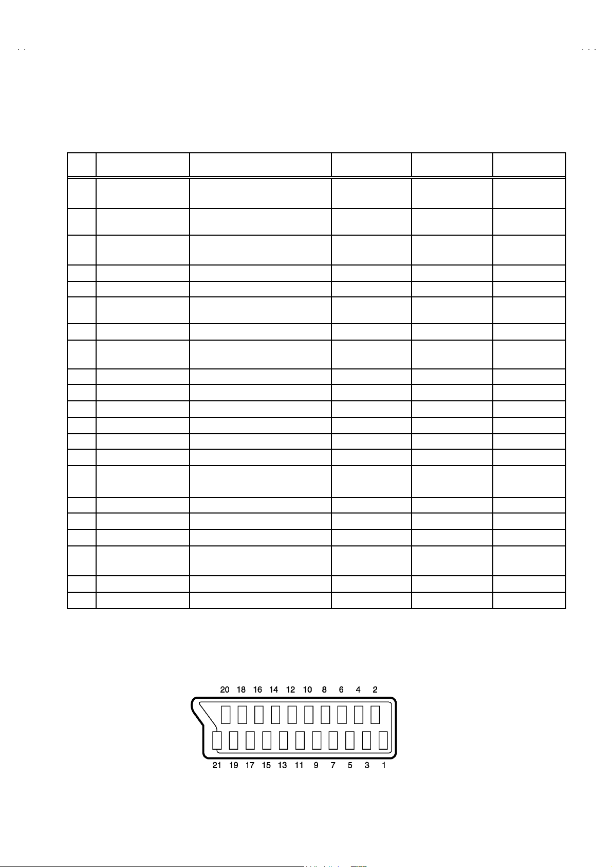
■■■■21-pin Euro connector (SCART socket) : EXT-1 / EXT-2 / EXT-3
(P-P= Peak to Peak, S-W= Sync tip to white peak, B-W= Blanking to white peak)
Pin
Signal Designation Matching Value EXT-1 EX T-2 EXT-3
No .
1 AUDIO R o ut put 50 0mVr ms( N ominal),
Low impedance
2 AUDIO R i n put 50 0m Vr ms( N ominal),
High i m pe da nce
3 AUDIO L output 50 0mVr ms( N ominal),
Low impedance
4 AUDIO GND ○○○
5 GND (B)
6 AUDIO L input 500mVrms(Nominal),
High i m pe da nce
7B input 700mV
8 FUNCTON SW
(SLOW SW)
9 GND (G)
10 SCL3 NC ○ NC
11 G in put 70 0m V
12 SDA3 NC ○ NC
13 GND (R)
14 GND (YS) ○ NC NC
15 R / C input R : 700mV
16 Ys i n put
17 GND(VIDEO outp ut) ○○○
18 GND(VIDEO input) ○○○
19 VID EO output 1V
20 VID EO / Y i np ut 1V
21 COM MON G ND ○○○
Low : 0-3V, High : 8-12V, High
impedance
C : 300mV
Low : 0 - 0.4, High : 1 - 3V, 75Ω○
, 75Ω○NC NC
B- W
, 75Ω○NC NC
B- W
, 75Ω
B-W
, 75Ω
P- P
(Nega tiv e g oin g sync ), 75Ω○
P- P
(Nega tiv e g oin g sync ), 75Ω○ ○ ○
P- P
○
(TV OUT)
○○○
○
(TV OUT)
○○○
○○○
○○○
○○○
○○○
○
(only R)
(TV)
○
(LINE OUT)
○
(LINE OUT)
○
(only C)
NC NC
○
(LINE OUT)
NC
NC
○
(only C)
NC
[Pin assignment]
No.51952
3
Page 4

A
V28CT1EPS / AV28CT 1EPB
SAFETY PRECAUTIONS
1. The d es ign of th is product con ta ins sp ec ial har d ware , many
circuits and components spe cially for safety purp oses. For
con tinu ed pr ot ection , n o chan g es sh ou ld b e ma de to the orig inal
d esi gn un l ess auth oriz ed in writi n g by th e ma nu fact urer.
Replac em en t p arts m ust be ident ic al to thos e u sed in th e or i ginal
ci rcu it s. Serv ice s ho uld b e perfor med by qualif ied p ers on nel
on ly.
2. Alte rati on s of t he desig n or cir cuitry of t he pr od ucts sh ould not be
made. Any design alterations or additions will void the
manufact ur er 's warrant y and will f urth er r eliev e t he ma nu factu r er
of r esp onsi b ility for per so na l injur y or p roperty dam ag e resul t in g
th erefr om.
3. Many el ectr ical an d m echanica l p ar ts in th e pr od ucts ha ve
special safety-related characteristics. T hese characteristics are
oft en no t e v ident f r om v isua l i nsp ection n or ca n t he pr o tec t io n
aff or de d by th em nece ssar i l y be ob tain ed b y u s ing replacem en t
com po ne nts ra ted f or hi g he r voltag e, w att ag e, etc. R ep l acement
p arts whic h ha ve th ese sp eci al s afet y ch ar ac t er ist ics are
ide ntified i n the parts list of Servic e m anual. El ectric al
components having such features are identified by shading
on the sch e mat ic s and by (
manual. The us e of a substitute r ep la cem en t whic h do es n ot
h ave th e same saf ety ch ar act er ist ics as t he r eco mmen de d
replac em ent part sh own i n th e p ar ts l i st of S er vi ce man ual may
cause shock, fire, or other hazards.
!!!!
) on the parts list in Service
4. Do n't short between the LIVE s ide ground and ISOLATED
(NEUTRAL) s ide ground or EARTH side ground when
repairing.
Some model's power circuit is partly different in the GND. The
diff er enc e of th e GND i s s ho wn b y th e LIV E : (") side GND , the
ISO LATED(NEUT RAL) : ( #) side GND and EARTH : ($) side
GND. Don't sh ort b et ween th e LIV E sid e GN D and
ISO LATED(NEUT RAL) side GND or EARTH side GND an d
n ever m ea s ur e w it h a m ea suring a ppa r atus ( osc illos cop e etc.)
th e LI VE si d e GND an d IS OLA TED (NE UTR AL ) s ide G ND or
EARTH side GND at th e s ame tim e.
If above note will not be kept, a fuse or any parts will be broken.
5. If any repair has been made to the chassis, it is recommended
th at t he B1 set ti ng s hou l d b e ch eck e d or adju ste d ( Se e
ADJUST MENT OF B1 POWE R SUPPL Y) .
6. The hi gh volta ge app lie d t o the pictu r e tu be mu st con form wit h
th at s p ecified in S ervi ce manual. E xcessi ve high volt ag e c a n
cau s e an i ncr e ase i n X- R ay em i ssi on , ar c ing an d possi b le
component damage, therefore operation under excessive high
voltage conditions should be kept to a minimum, or should be
preve nt ed. If s ever e arc ing occ ur s, r emove t he AC pow er
immed i ate ly an d de ter m i ne th e c a use b y visua l insp ec t io n
(inc or rect ins tal lat i on, cracke d or melte d high v o lt age har n es s,
p oor so lder i ng, et c.). To maint ai n the p roper min im u m le vel of
sof t X-Ray em ission, c omponen ts in th e high vol tag e ci r cui try
incl ud ing t he pi ct ur e tu be must be t he e xact r ep l aceme nts or
alte rn at i ves ap pr ove d b y th e ma nuf act urer of th e c om pl et e
product.
7. Do n ot c hec k high vol t age b y draw ing an ar c. Us e a high vol t age
meter or a hi g h v oltag e pr ob e wit h a V TVM. Discharge th e
picture tube before attempting meter connection, by connecting
a cl i p lead to th e gr ou nd f ra me and c onn ec ti n g th e oth er end of
the lead through a 10kΩ 2W resis to r to the anod e butt on .
8. When s e r vice is r equ ired, ob serve th e origi na l lea d dr ess . Extr a
prec aut ion sh ou ld b e g iven t o ass ur e corr ec t l ea d dr ess i n the
high vol tag e c ircui t a r ea. W her e a s hort ci r cuit h as oc cu rre d,
th ose co mp on ent s tha t i ndi ca te evide nce of ove r hea ting sho ul d
b e re plac e d. A lways us e th e ma nuf act ur er's r ep l acement
components.
9. Isolation Check
(1) Di electric Strength Test
(2) Leakage Current Check
AV28CT1EPS / AV28CT1EPB
(Safety for Electrical Shock Hazard)
Af ter re- ass emb l in g th e pr odu c t, al w ays per f orm an i sol at ion
ch ec k on the expo sed metal parts of t he c abin et ( a ntenn a
ter m inals, video /audio inpu t and ou tput t erminals , C on trol kn obs,
metal cabi n et, scr ew he ad s, ea r ph one j ack, con trol s haf ts, etc.)
to be s u re th e p roduct is s af e t o ope r ate with ou t dan ger of
elect ri cal s hoc k.
The i solation be tw een the A C prim a ry c ircu i t an d al l me tal p ar ts
exp osed t o th e us er , p arti cular l y any e xp osed met al p art having a
retu rn p ath to t he chass is sho uld withs tan d a vol t age of 3 000 V
AC (r.m. s.) for a period of one second.
(. . . . W it hstan d a vo lt ag e of 1 10 0V A C (r .m. s.) t o an ap pl ianc e
rate d up to 12 0V , an d 3 00 0V AC ( r .m. s.) to an ap pl ian ce r at ed
200V or more, for a period of one second.)
This meth od of test requi res a t est equi pmen t n ot gen erally found
in t he servic e trad e.
Plug th e A C line c ord direc t ly in to the A C ou tl et ( d o not use a lin e
isol ati o n tr ansf or m er during this check .) . Usi n g a " Lea kag e
Curr ent T este r", me asur e th e lea kag e cu rre nt f rom each exp osed
metal p art of the cabinet, p art icu larly any expos ed me tal p ar t
h avi ng a re tur n path to the c h assis , t o a kn ow n go od ea rt h
ground (water pip e, e tc.) . An y l eaka ge curren t m ust n ot e xceed
0.5mA AC (r.m.s.).
Howev e r, i n tr op ic al area , th is must no t exce ed 0.2 mA AC
(r.m.s. ).
""""
Alternate Che ck M et hod
Plug th e A C line c ord direc t ly in to the A C ou tl et ( d o not use a lin e
isol ati o n tr an s for m er dur ing t his che ck .) . Use an AC vo lt me ter
h avi ng 1 00 0 ohms pe r volt or mor e s ens itivity i n th e fo llow i ng
manner. Con nec t a 1 50 0Ω 10W res ist or par a lle led by a 0 .1 5µF
AC-type c apa citor bet we en an ex po sed met al pa rt a nd a kno wn
g ood e ar th gro un d (water pipe , etc.). M eas ure th e A C v o lt ag e
acr oss th e r es ist or w i th th e AC vo ltm eter . M ove th e r esis tor
con nec ti on to each exp ose d metal part, part ic ularly any exp osed
metal p art havin g a retu rn pat h to t he chassis, an d m eas u r e th e
AC vol tag e ac ro ss the r es ist or. No w , rev er se th e plu g in th e AC
ou tl et and re pe at eac h mea s ur emen t. Any volt ag e me asured
must not exc eed 0.75V AC (r.m. s.). This c orre sponds to 0.5m A
AC (r.m. s.).
Howeve r, in tropical are a, this must not exceed 0.3V AC ( r .m.s.).
This corresponds to 0.2mA AC (r.m.s.).
AC VOLTMETER
(HAVING 1000 Ω /V,
OR MOR E SENSITIVITY)
0.15μF AC-T YPE
PLACE THIS PROBE
1500 Ω 10W
GOOD EARTH GROUND
ON E A C H EX PO SE D
ME T AL PA RT
4
No.51952
Page 5

A
V28CT1EKS / AV28CT 1EK
B
A
S
V28CT1EI
SAFETY PRECAUTIONS
1. The design of thi s pro du ct c ont ains spe ci al hard ware and many
circuits and components spe cially for safety purp oses. For
con tinu ed pr ot ection , n o chan g es sh ou ld b e ma de to the orig inal
d esi gn un l ess auth oriz ed in writi n g by th e ma nu fact urer.
Replac em en t p arts m ust be ident ic al to thos e u sed in th e or i ginal
ci rcu it s. Serv ice s ho uld b e perfor med by qualif ied p ers on nel
on ly.
2. Alte rati on s of th e des ig n or ci rc uitr y of th e pr od uct sho uld no t be
made. Any design alterations or additions will void the
manufact ur er 's warrant y and will f urth er r eliev e t he ma nu factu r er
of r esp onsi b ility for per so na l injur y or p roperty dam ag e resul t in g
th erefr om.
3. Man y elec tr i cal a nd me chanical p ar ts in the pr od uct h ave spe ci al
saf ety- r elat ed ch ar act erist ics. Thes e characteri stics a re oft en not
evi d ent from visu al insp ec ti o n no r can th e p rotect i on af forde d by
th em n ecess ar y be o bta in ed by usi ng replac em ent c om pon en ts
rate d for hi gh er volta ge, wa tta ge , etc. R e pl acement p art s whic h
4. The leads i n the p rodu cts ar e r ou ted an d d r es sed wit h t ies,
AV28CT1EKS
/ AV28CT1E KB
AV28CT1EIS
h ave th ese spe c ial s af et y c har ac ter istic s ar e i d ent if ied in th e
Pa rts Lis t of Serv ice Ma nu al . Elec tr i cal compon en ts h avi ng suc h
fe atur es are identifi ed b y sh adin g on the sche ma tic s and by (!)
on t he Par ts List in the S ervi ce Manual. The u s e of a s ub stitut e
replac em ent w hi ch d oes no t h av e th e s am e saf ety
ch ar ac ter i stic s as the re c om mend ed r eplace ment part sho wn in
th e Par ts List of Se rvi ce Man ual may cause sh ock , fire, or ot her
hazards.
cl am ps, tu bi ng ’ s, b ar rie rs a nd t he like t o be s epa ra ted from live
p arts, high t emperature pa rts, m oving parts an d / or sh arp ed ges
for t he p reven ti on of e lectr i c sh oc k and fire h azar d. W he n
ser vic e is r e quired , the or igin al le ad r outin g and d ress sh ould b e
ob ser v ed , and it sh oul d b e co nfi r m ed t hat th ey h ave bee n
retu rn ed to no rm al , aft er re- as se mblin g.
WARNING
1. The eq uipme nt h as b ee n d esig ned a nd m anu fact ur ed to me et i nternatio nal saf ety sta nd ards.
2. It is t he leg al resp onsib ili ty o f th e re pa irer t o e nsure th at thes e safet y sta ndar ds are mai nt aine d.
3. Rep airs mu st b e m ad e i n acc ordan ce with the rele vant saf ety st an dar ds .
4. It is ess en ti al t hat saf ety cri ti cal c ompon ent s are replac ed by a pp ro ved part s.
5. If main s vol t age selec tor is p rovide d, ch eck s etti n g f or loca l vo ltag e.
No.51952
5
Page 6
A
V28CT1EPS / AV28CT 1EPB
A
A
(
)
(
)
)
(
)
)
(
)
)
(
)
)
V28CT1EKS / AV28CT 1EKB
V28CT1EIS
FEATURES
"
By pref er enc e, users can s ele ct th e pictur e size fr om REG UL AR ,
PANORAMIC, FULL, 14:9 ZOOM, 16: 9 ZOO M, 16 :9 ZOOM SUB
TITL E mod es. W he n th e TV u ni t r e ceived W SS pict ur e si gn al, th e
pictu re can be ch an ged t o 16:9 ZOOM m ode autom atically.
" The T ELE TEXT S YSTE M has a b uilt - in FAS TEXT, TOP (On l y
AV 28CT1 EPS / EPB) an d W ST s ystem.
" Be c aus e th is T V un it cor r espon ds t o m ultiplex br oa dc a st, u sers
can enjoy music programs and sporting events with live realism.
In ad di ti on , BI LIN GUAL programs can b e h ear d in th eir or i g in al
language.
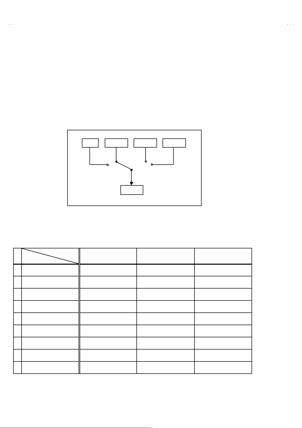
TV EXT-1 EXT-3
EXT-2
"
Users can make VCR dubbing of picture and sound by controlling
th e AV s elec tor to se lec t an optiona l so urc e at th e EXT- 2 outp ut
sh own in figu re.
EXT-4
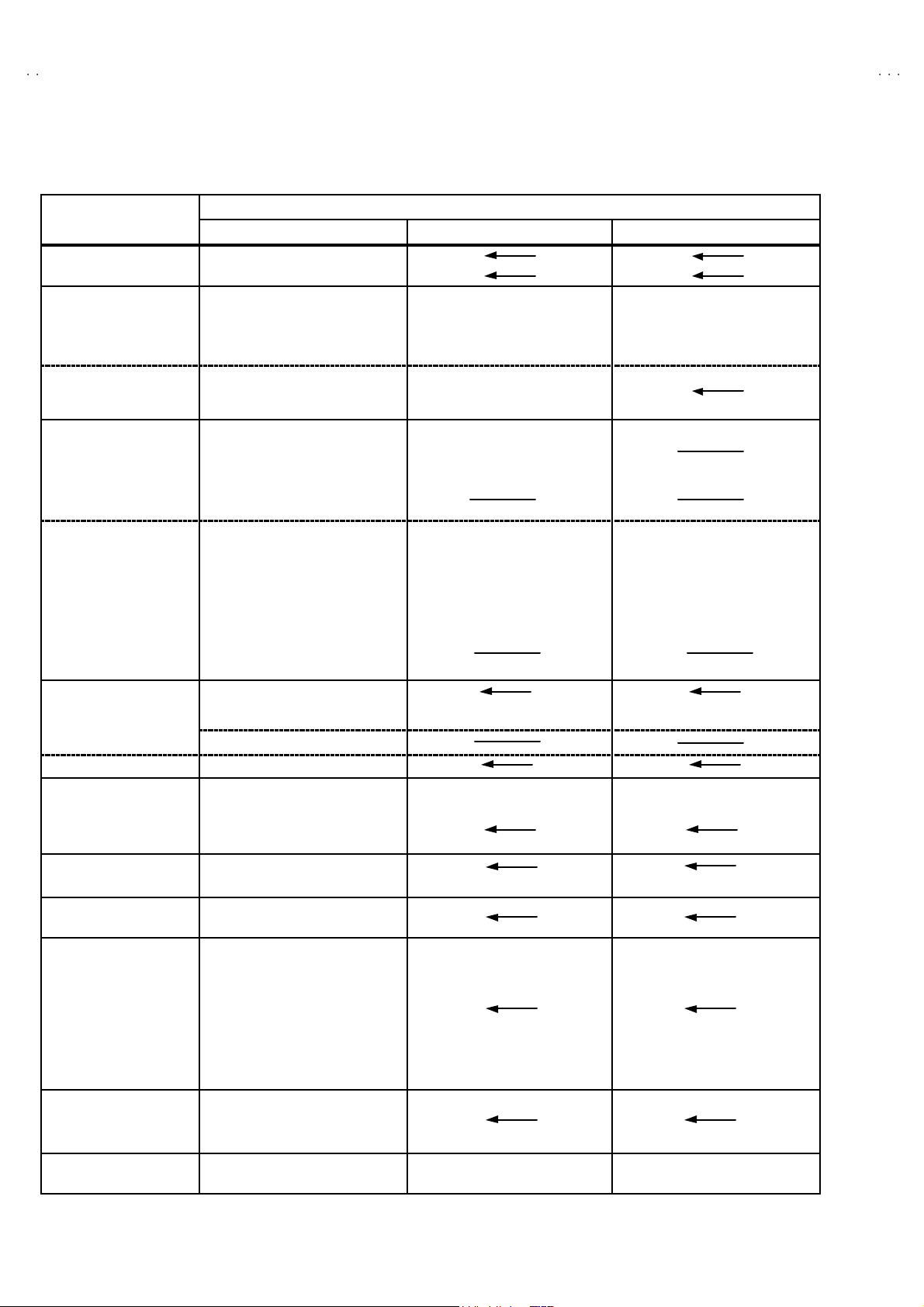
MAIN DIFFERENCE LIST
Model Name
!!!!
Part Name
MAIN PWB SJK-1716A-U2
AV SEL. PWB SJK0S712A-H3 ← SJK0S912A-H3
FRONT CABINET ASSY
!
POWER CORD QMPK160- 185- JC QM PN130-185-JC ←
!
RATI NG LABEL
EURO LABEL
!
INST BOOK
REM OTE CO NT ROL
UNI T
S. DIAGRAM
ONLY ITALY(SERVICE)
AV28CT1EPS / EPB AV28CT1EIS AV28CT1EKS / EKB
LC10001-006C-U
LC10001-007B-U (EPB)
LC11415-001A-U
LC11415-002A-U (EPB
AEM1064-014-E (EPS)
AEM1064-015-E (EPB)
LCT1137- 001A- U
LCT1136- 001A- U (EPB
RM-C54H-1C (EPS)
RM-C50-1C (EPB)
28CT1EP-HSA-E
EPS
EPS
EPS
←
LC10001-006C-U
LC11372-003A-U
AEM1064-013-E
LCT1138- 001A- U LCT1138- 001A- U
RM-C5 5H- 1C
××
EPS
SJK-1916A-U2
LC10001-006C-U (EPS
LC10001-007B-U (EPB)
LC11364-005A-U
LC11364-006A-U (EKB
AEM1064-011-E (EKS)
AEM1064-012-E (EKB)
RM-C55H-1C (EKS)
RM-C51-1C (EKB)
EKS
6
No.51952
Page 7
A
V28CT1EKS / AV28CT 1EK
B
A
B
A
S
V28CT1EPS / AV28CT 1EP
SPECIFIC SERVICE INSTRUCTIONS
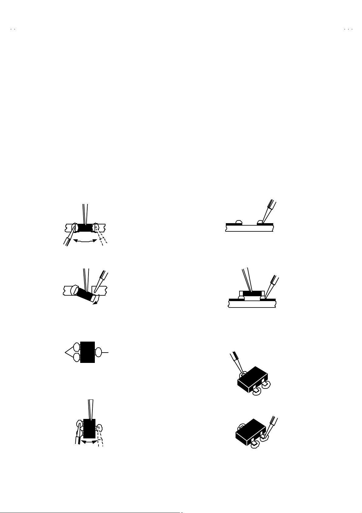
REPLACEMENT OF CHIP COMPONENT
! CAUTIONS
1. Avoid heating for more than 3 seconds.
2. Do n ot rub t he el ect rodes an d the resis t p arts of the p att ern.
3. When removi ng a c hip part, mel t the s older ad equ atel y.
4. Do n ot reuse a ch ip p art afte r removi ng it .
! SOLDERING IRON
1. Us e a hi g h ins ulati o n s older i ng i r on with a t hin po in ted end of it .
2. A 3 0 w s oldering ir on is r ec ommend ed for easi l y r emovi ng par ts .
!
REPLACEMENT STEPS
1. How to remove Chip parts
####
Resi st ors, ca pacit ors , etc
(1) As sh own in the f igure, pu sh th e pa rt with tw ee zers and
alte rn at el y m el t the sol de r at each en d.
(2) Sh if t w ith tw eeze rs and r em o ve th e ch ip p ar t.
#### Trans isto rs, dio des, va ria bl e r esistors, et c
(1) Ap ply e xt ra so lder to ea ch lead .
SOLDE R SOLDE R
2. How to install Chip parts
####
Resi st ors, ca pacitors , et c
(1) Ap ply sold er to th e pattern as ind ic ated in the fi gure.
(2) Gr asp t he ch ip p art with twee zers and pl ac e it on th e s old er.
The n hea t and melt th e so lder a t b oth en ds of t he chip part.
#### Trans isto rs, diodes , varia bl e r es ist or s, et c
(1) Ap ply sold er to th e pattern as ind ic ated in the fi gure.
(2) Gr asp th e chip p art w it h twe eze rs and p lace it on th e so lder.
(3) First solder lead A as indicated i n t he figure.
V28CT1EI
A
(2) As sh own in the f igure, pu sh th e pa rt with tw ee zers and
alte rn at el y m el t the sol d er at eac h le ad . Shi ft and remove the
chip part.
(4) Then so lder le ads B and C.
Note : A fte r re moving the part, r emove remain ing so lder fro m the
pattern.
No.51952
C
A
C
B
B
7
Page 8
A
V28CT1EKS / AV28CT 1EKB
A
A
V28CT1EPS / AV28CT 1EPB
V28CT1EIS
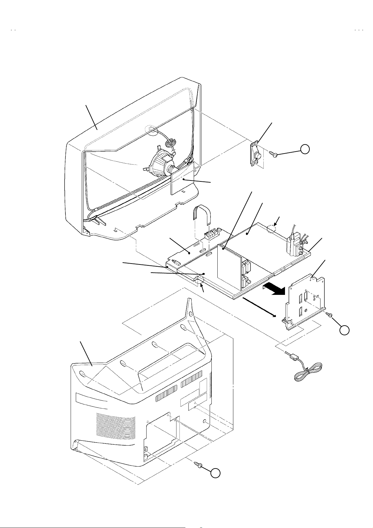
DISASSEMBLY PROCEDURE
REMOVING THE REAR COVER
1. Unp lug t he powe r c ord.
2. Remove the 14 screws marked“
3. Withdr a w t he rear co ver to wa rd you .
REMOVING THE CHASSIS
"
After removing the rear cover.
1. Sli ght ly rai se th e bo th si de s of th e c hass is by h and and re mo ve
th e tw o claws u nd er th e b oth s id es of the chassis fr om t he front
cab inet .
2. Withdr a w t he chass is backward.
(If n ecessary, take off the wire clamp, conne ctors etc.)
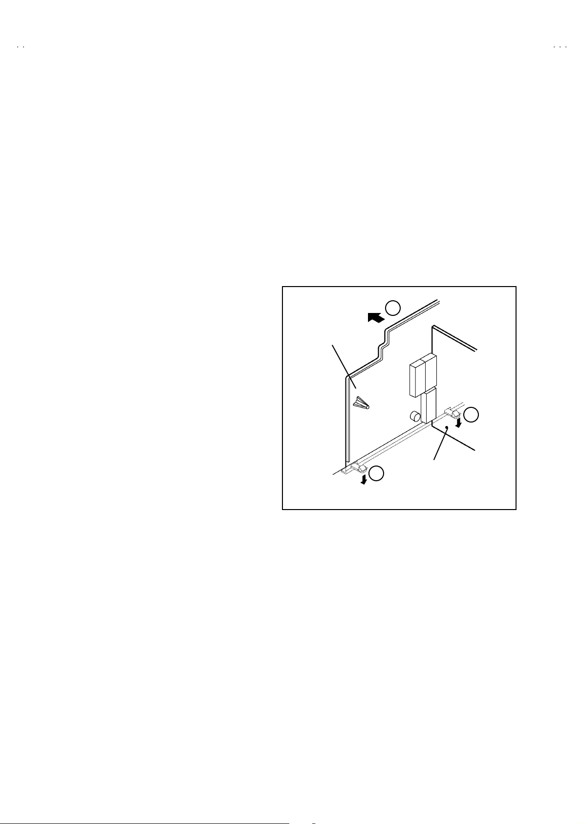
REMOVING THE AV TE RMINAL BOARD
" After removing the rear cover.
1. Remove the 2 scr ew s mar ked“
2. Remove the claws marked “
shown in Fig. 2.
3. Remove th e to p of t he A V TE RMINAL BOA RD slight ly in th e
direc ti o n of arr ow “
” as sh own in Fi g. 2 .
$$$$
”as sh own i n t he F ig. 1.
!!!!
”as sh own in th e Fig. 1.
""""
” u nde r the C H ASS IS as
####
D
AV TERMINAL
BOARD
REMOVING THE SPEAKER
"
After removing the rear cover.
1. Remove the 2 scr ew s mar ked“
2. Fol low th e s ame st eps when removi ng th e other ha nd speake r.
”as shown in Fig. 1.
%%%%
CHECKING THE PW BOARD
To c h eck the b ack side of th e PW B oard.
1) Pull out the ch assis . ( Refe r to RE MOVING TH E CH ASSIS).
2) Erect the c hassis vertically so that you can easily check the
b ack si de of th e PW B oard.
[CAUTION]
" When e recting the chassis, be careful s o that there will be no
contacting with other PW Board.
" Be for e turning on po wer , make sure t ha t the w i re c o nn ec to r i s
properly connec ted.
"
W hen co ndu cting a ch eck w ith p ow er su ppli ed , b e sure to c onfir m
th at t he CRT E ART H WI RE (B RA ID ED AS S’Y) is co nne cted t o
th e C RT SOCKE T PW b oar d.
WIRE CLAMPING AND CABLE TYING
1. Be sure t o cla mp the wir e.
2. Never r em o ve th e c able tie used f or ty ing th e w i res toge the r.
Sh ould it be in adve rt ent l y rem oved, b e sure to ti e th e wi res w it h
a n ew c able ti e.
C
AV SE L PWB
C
Fig . 2
8
No.51952
Page 9
A
B
A
B
A
S
FRONT CABINET
CRT
SOCKET
PWB
V28CT1EKS / AV28CT 1EK
V28CT1EPS / AV28CT 1EP
V28CT1EI
SP EAKER
E
AV SE L . P WB
POWER & DEF. PWB
CLAW
C ONT RO L BASE
REAR COVER
FRONT CO NTROL
PWB
MAIN PWB
CHAS SIS
AV TERMINAL
BOARD
CLAW
B
A
Fig . 1
No.51952
9
Page 10
A
V28CT1EKS / AV28CT 1EKB
A
A
V28CT1EPS / AV28CT 1EPB
V28CT1EIS
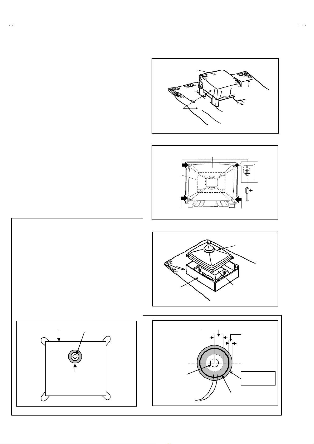
REMOVING THE CRT
∗
Replac em en t of the CRT sho ul d be per formed b y 2 or mor e
p ers ons.
• After removing the cover, chassis etc.,
1. Pu tting the CR T c han ge ta ble o n sof t c loth , th e CRT cha ng e ta ble
sh ould al so b e c over ed w ith s uch soft clot h (sho wn in Fi g. 5).
2. While k ee pi n g th e surf ac e of CRT dow n , m ou nt the TV s et on t he
CRT change table balanced will as shown in Fig.6.
3. R em ove 4 s c rews mark e d by arro ws with a box typ e scr e w dr iver
as s hown in Fig. 6.
• Si nc e th e cab inet w ill dr op wh en scr ew s h ave b een remo ved, be
sure t o su pport t he cabinet with h ands.
4. After 4 screws have been removed, put the cabinet slowly on
cloth (At th is time, be carefully so as not to damag e the front
sur fac e of th e c abin et) sh own in Fig.7 .
• The CR T sh ould b e ass em bled acc or ding to th e opp osi te
sequence of its dismounting steps.
∗
T he C RT chang e t able sh ould pr ef erab ly b e small er t hat th e CRT
sur fac e, and its height b e about 35c m.
CRT CHANGE TABLE
AP PROX.
35 cm
CLOTH
Fig. 5
CRT
CRT
CHA NGE
TABLE
BOX
TYPE
SCREW
DRI VER
COATING OF SILICON GREASE FOR EL ECT RICAL
INSULATION ON THE CRT ANODE CAP SECTION.
•
Subs e qu ent to re pl ac ement of t he C RT an d HV tr an sfor m er o r
repair of t he an od e cap, etc. by d is mount i ng the m, be sure to coa t
si lic o n g rease for electric al ins u l ati o n as sh ow n in Fig.8 .
W ipe a r oun d t he an ode b utt on with cl ea n and dry c lot h. (F i g. 8)
Coat si l ic on greas e on t he sect ion arou nd th e a no de bu tt on. At
this time, take c are so that any silicon greases dose n ot stic k to
the ano de button . (F ig.9 )
★★★★
Silicon grease product No. KS - 650N
CRT
An od e b utton
Silic on greas e
coating
CABINET
Ap prox.
20mm (Do not
coat grease on
this s ection
An od e b utton
(No s ti cki ng of
silicon grease)
Fig. 6
CRT
CRT
CHANGE TA BLE
Fig. 7
Silic on greas e
sh oul d be coa ted
b y 5mm or m or e
fr om th e outs id e
diameter of
an od e c ap.
Coat ing posi t io n
of silico n gr eas e
An od e ca p
Fig. 8 Fig. 9
10
No. 51952
Page 11

A
B
A
B
A
S
REPLACEMENT OF MEMORY ICs
1. Memory ICs
This TV use memory ICs. In the memory ICs, there are memorized data
for cor r ectl y op erating th e video an d def l ection cir cu its . W h en r ep lac ing
memory IC s, b e s ure t o us e IC s wri tte n with th e initial values of da ta.
2. Procedure for replacing memory ICs
PROCE DURE
(1) Powe r off
Switch the p ower of f and un plug th e pow er cor d fro m t he ou tlet.
V28CT1EKS / AV28CT 1EK
V28CT1EPS / AV28CT 1EP
V28CT1EI
(2) Rep la ce ICs.
Be sure to use memory ICs writt en with the in it ial data values.
(3) Powe r o n
Plug th e p ower c ord i nt o the outlet a nd swit ch t he po we r on .
(4) Check an d s et SY STEM CONSTAN T SET :
It must not adjust wit hout sig nal.
****
1) Pr ess th e INFORMAT I ON ke y and th e MUT IN G k ey of th e
REMOTE CONTROL UNIT simultane ous ly.
2) The SERVICE MENU screen of Fig. 1 will be displayed.
3) Whi le th e S ERVICE ME NU is displ a yed, p r ess t he
INFORMATION key and MUTING key simultane ously, and the
SYSTEM CONSTANT SET screen of Fig. 2 will be display ed.
4) Check the se tting va lues of the S YSTEM C ONST A NT SET of
Table 1. If the value is d ifferent, select th e s ettin g item with th e
FUNCTION U P/ DOWN key, and s et the correct va lue with the
FUNCTION - /+ ke y.
5) Press the MENU key to memorize the setting va lue.
6) Pres s t he IN FOR MATION ke y t wice, a nd r etu rn t o th e no rmal
screen.
SE RV ICE MEN U
1. IF 2. V/C
3. AUDIO 4. DEF
5. VS M PRES ET 6 . VP S
7. AUTO PROGRAM (OFF)
1- 7 : SE LECT : EXI T
Fig.1
SY STE M CON ST AN T S ET
MO DE L= JK _EU R O (V
COUNTRY :
INCH :
MO DE L : W T
- + : STORE : EXIT
OK
JVC JK- II EU RO V00
******** - *****
Fig.2
*.****
**
**
)
(5) Setting of re cei ve ch anne ls
Se t the rec eive c h an ne l.
NAME OF REMOTE CONTROL KEY
Names of key
ke y
For setting , ref er to the OPERATIN G INSTRUCTIONS.
INFORMATION
iiii
(6) User se tting s
Check th e us er sett in g values of T ab le 2, an d if sett in g value is
MU T I N G
diff er ent , set the c orr ec t val u e.
For setting , ref er to the OPERATIN G INSTRUCTIONS.
OK
▼
▼
(7) Setting of SERV ICE MENU
Ve rif y the s et ting it ems of th e SER VIC E MENU of Tab le 3, an d r ese t
where necessary.
ME NU
FUNCTION UP/DOWN
For setting , ref er to the SERVICE ADJUSTMENTS.
▼
FUNCTION -/+
▼
No. 51952
11
Page 12

A
V28CT1EKS / AV28CT 1EKB
A
A
V28CT1EPS / AV28CT 1EPB
V28CT1EIS
SETT I NG VALU ES OF SYST EM CONS TANT SE T (TABLE 1)
Setting item Setting content
AV28 CT1 EPS / EPB AV28 CT1 EIS AV28CT1EKS / EKB
Setting value
COUNT RY EP IR EK
INCH 28 28 28
MO DE L W T
EK EPIR
WT
3224 28
WR
USER SETTING VALUES (TABLE 2)
PICTURE SE TTING EX T SET TI NG
TINT
CONTRAST
BRIGHT
SHAR P
COLO UR
ECO MOD E
PICTURE F EAT URES FEATUR ES
AUT O VNR
COLOUR S YSTEM
4:3 AUT O ASPE CT
SOUND SETTING INSTALL
STEREO / Ⅰ・Ⅱ
BA SS
TR EBL E
BALANCE
HYPE R S OUND
COOL
REFER to VSM PRESET
NOTHING
AUT O
TV : Acco rding t o preset CH
EXT : AUTO
PA NO RA MI C
+8
CENTER
OFF
ID
S-IN
DUB BING
SLEEP TIMER
BLUE BA CK
CHI LD LO CK
DECODER (EXT-2)
LA NG UA G E
EDIT/MANUAL
DEMO OFF
BLANK
BLANK
EXT- 1→EX T-2
OFF
ON
ID : No.****
ALL CH OFF
OFF
ENGL ISH
PRES ET CH on ly
The others : BLANK
SERVICE MENU SETTING ITEMS (TABLE 3)
Setting item Setting value Setting item Setting value
1. IF VCO 4. DEF. 1. V-SHIFT
2. V / C 1. CUT OFF
1. AUDIO
(Do not adju st)
2. DRI VE
3. BRIGHT
4. CONT.
5. COLO UR
6. HUE
7. BLAC K O FFS ET ( Onl y SEC AM)
8. SHAR P
9. PURITY
1. CONC LIMIT
2. A2 ID THR
3. AL C
4. BA SS
5. TR EBL E
5. VS M PRESE T
COOL
NORMAL
WARM
6. VP S
(Do not adju st)
7. AUT O PROG RAM
(Do not adju st)
2. V-SIZE
3. SUBT IT LE
4. H-CENT
5. H-S IZE
6. EW - PIN
7. TR APE Z
8. EW. COR. L
9. EW. COR. H
10. V. S- COR
11 . V- LIN
12. H- BL K-R
13. H- BL K- L
14. V-EHT
15 . H - EHT
16. EHT-GAIN
1. BRIGHT
2. CONT.
3. COLO UR
4. SHAR P
5. HUE
6. R DRIVE
7. B DRIVE
VP S
PDC
ON / O FF
12
No. 51952
Page 13

A
B
A
B
A
S
SERVICE ADJUSTMENTS
BEFORE STARTING SERVICE ADJUSTMENT
1. There ar e 2 w ays of ad ju st ing this TV: One is wi th the
REMOTE CONTROL UNIT and the other is the conventional
method using adjustment pa rts and components.
2. The s etting (adjustment) using the REMOTE CONTROL
UNIT is made on the basis of th e init ial setting values. The
se tting va lues which adj u st the scree n to t h e opt imum
condition can be different from the initial setting values.
3. Make s ur e th at conn ec t i on i s c orr ect ly ma de t o AC p ower
source.
4. Tur n on the power of th e TV and measu r in g i nstrument for
warmi n g u p for at l east 30 minut es b ef ore sta rt ing adju stment .
5. If th e r ec eive or i np ut si g nal is not speci fi ed , use t he m ost
ap prop riate s igna l f or a dj ust ment.
6. Never tou c h p ar ts ( suc h as var i ab le resist or s, tran sformers an d
condensers) not shown in the adjustment items of this service
adjustment.
7. Preparatio n f or ad j ustment ( pr es etting):
Unles s oth er wis e speci fi ed i n the a djust ment it em s, p r eset th e
follo wing funct io ns with the REMOTE CONTROL U NIT :
" Setting position
PICTURE MODE (VSM) NORMAL
SLEEP TIMER OFF
BALANCE CE NTER
ZOOM PANORAMIC
V28CT1EKS / AV28CT 1EK
V28CT1EPS / AV28CT 1EP
V28CT1EI
MEASURING INSTRUMENT AND FIXTURES
1. DC voltmeter (or digit al voltmeter)
2. Oscilloscop e
3. Si gn al g enerat or (Patt ern g en erator) [ PAL / SE CA M / NTSC ]
4. Remote control unit
ADJUSTMENT ITEMS
●
B1 power supply check.
●
Adjustment of FOCUS.
●
IF ci rcuit a djust me nt.
●
VS M p r eset ad ju st s ettin g.
●
VIDEO / CHROMA circ uit adjustment.
●
DEFLECTION circuit adjustment.
●
H. BLANKIN G ADJUSTME NT.
●
AUDIO circuit adjustment. (Do not adjust)
No. 51952
13
Page 14

A
V28CT1EKS / AV28CT 1EKB
A
A
5
V28CT1EPS / AV28CT 1EPB
V28CT1EIS
ADJUSTMENT LOCATIONS
FRON T
FRONT CONTROL PWB
F90 1
PW
POWER SW
FRON T
MAIN PWB POWER&DEF PW B
CN001
AV SEL PWB
CN006
CN001
MEMORY
IC702
IC701
F
SP R
SP L
FRON T
W DEG
TUNER
CRT SOCKET PWB
T P-47R
T P-47G
CN008
TP-E
IC301
CN008
(SOLDER SIDE)
T P-47B
E1
CN009
TOP
CN009
HV
X
1
1pin:B1( TP-91)
2pin:NC
3pin:NC
4pin:NC
5pin:GN D
FOCUS
SCREEN
14
No. 51952
Page 15

A
V28CT1EKS / AV28CT 1EK
B
A
B
A
S
y
y
V28CT1EPS / AV28CT 1EP
V28CT1EI
BASIC OPERATION SERVICE MENU
1. TOOL OF SERVICE MENU OPERATION
Operate the SERVICE MENU with the REMOTE CONTROL UNI T.
2. SE RVICE MENU ITEMS
With the SERVI CE MENU , v ar iou s s ett ings ( ad ju stments) c an b e m ade , and th ey a re b roadly clas sif ied i n th e f ol lowing i te ms of s et tings
(adjus tm ents ):
(1) 1. IF ・・・・・・・・・・・・・・・・・・・・ ・・・ This mode adjust s the se tting values of the IF circuit.
(2) 2.V /C ・・・・・・・ ・・・・・・・・・・・・・ ・・ This mode adjust s the se tting values of the VID EO / CH ROMA circui t.
(3) 3.AUDIO ・・・・・・・・・・・・・・・・・・・ This mode adjusts the setting values of the multiplicit y SOUND circuit.
(4) 4. DEF ・・・・・・・ ・・・・・・・・・・・・・ ・ T hi s m ode adjust s th e setti ng values o f the DE FLECT ION c ircui t f or eac h as pect m od e g i ven be low.
REGULA R (50/ 60 Hz)
PA NO RA MI C ( 50 / 60 Hz)
14 :9 Z O OM (50/ 60 Hz)
16 :9 Z O OM (50/ 60 Hz)
SUB TI TLE (50/ 60Hz)
FU LL (50/ 60Hz)
(5) 5.V SM PRESET ・・・・・・・・・・・・・ This mode adjusts the initial setting values of COO L,NOMAL and WARM.
(VSM : Video Status Memory)
(6) 6.V PS ・・・・・・・ ・・・・・・・・・・・・・ ・ Thi s m ode sh ows the monitor of t he VPS a nd PD C .(Do not adjust).
(VP S : Vide o Pro gr am Syst em, PDC : Progra m Delive ry Code)
(7) 7. AUTO P ROGRAM ・・・・・・・ ・・ By t urni ng the p ower switch o n, you c an ge t the st ate of AU T O PR OG RAM. (Do not adjust)
3. BASIC OPERATION OF SERVICE MENU
(1) How to enter SERVICE MENU
Press the INFORM ATION key and the MUTING key of t he
REMO TE CONT RO L U NI T si mu lt an eou s ly, an d th e
SERVICE MENU screen of Fig. 1 will be displayed.
(2) Selection of S UB MENU SCREEN
Press one of keys 1~7 of the REMOTE CONTROL UNIT
an d sel e c t th e S UB M ENU SCR EEN ( See Fi g. 3 ), fo rm th e
SERVICE MENU.
SERV ICE MENU → SUB ME NU
1. IF
2. V / C
3. AUDIO
4. DE F.
5. VSM PRESET
6. VP S
7. AUTO PROGRAM
SE RVICE M ENU
SERVICE MENU
1. IF 2. V/C
3. AUDIO 4. DEF
5. VS M PR ES ET 6 . VP S
7. AUTO PROGRAM (OFF)
1-7 : SELECT : EXIT
Fig.1
NEME OF REMOTE CONTOROL KEY
Names of ke
INFORMATION
MUTI NG
MENU
FUNCTIO N UP/DOWN
FUNCTIO N -/ +
Fig.2
ke
iiii
OK
▼
▼
▼
▼
No. 51952
15
Page 16

A
V28CT1EKS / AV28CT 1EKB
A
A
V28CT1EPS / AV28CT 1EPB
V28CT1EIS
SERVICE MENU
SERVICE MENU
1. IF 2. V/C
3. AUDIO 4. DEF
5. VSM PRESET 6. VPS
7. AUTO PROGRAM (OF F)
1-7 : SELECT : EXI T
7. AU TO PRO G RAM
7. AUTO PROGRAM (OF F)
7. AUTO PROGRAM (ON )
Do not adjust
COOL
NOR MAL
WARM
1. BR IGHT
2. CONT .
3. COL OU R
4. SHA RP
5. HU E
6. R DR IV E
7. B DR IV E
Do not adjust
5. VSM PRESET
VSM PRESET
NOR MAL
1. BR IGHT
- + : STORE : EXIT
OK
VPS = 0000H(- - -)
PD C 8 / 30 / 1 = 0 404 H
***
6. VPS
VPS
: EXI T
1.IF (VCO)
VCO (CW)
**
** ....**
**
****
****
TOO HIGH
ABOVE REFER ENCE
JUST REFERENCE
BEL OW R EFE RE NC E
TOO LOW
2. V /C
V/C
PAL
1. CUT OFF ( R)
OK
- +
****
(G)
****
(B)
****
: ST ORE : EXI T
MHz
: EXI T
1. CUT OFF
2. DR IVE
3. BR IGHT
4. CONT .
5. COL OU R
6. HU E
7. BLAC K OFFS ET
8. SHARP (Do not adjust)
9. PUR ITY (Do not adjust)
3. AU DIO
AU DIO
1. CONC L IMI T 0AH
C AD B I TS = 00 00000 0
: ST ORE : EXI T
OK
- +
SU B M ENU 4. D EF
DEF PANORAMIC
1. V- SHIFT
: ST ORE : EXI T
- +
OK
Fig. 3 SUB MENU SCREEN
***
(**)
Do not adjust
1. CONC LIM IT
2. A2 ID THR
3. ALC
4. BA SS
5. TREBLE
1. V-SHIFT
2. V-SIZE
3. SUB TITLE
4. H-C ENT
5. H-SI Z E
Hz
**
**
****
6. EW -PIN
7. TRAPEZ
8. EW.COR.L
9. EW.COR.H
10. V.S-COR
11 . V-L I N
12 . H -BL K-R
13 . H -BL K-L
14. V-EHT(Do not adjust)
15 . H -EHT ( Do no t ad jus t)
16 . EH T-G A IN (D o n o t ad jus t)
16
No. 51952
Page 17

A
V28CT1EKS / AV28CT 1EK
B
A
B
A
S
V28CT1EPS / AV28CT 1EP
(3) Method of Setting
1) Meth od of Set ting 1. IF
[VCO]
① 1 Key ・・・・・・・ ・・・・・・・・・・・・・ ・・・・・ Select 1.IF.
② The VCO (CW) screen will be displayed in yellow when the AFC voltage is at a certain level and in blue when it is at other levels .
③ INFORMATION K ey ・・・・・・・ ・・・・・ Return t o the SE RVICE MENU scre en.
2) Meth od of s ett in g 2.V/C, 3.AUDIO, 4.DEF an d 5.VSM PRESET.
① 2~5 K ey・・・・・・・・・・・・・・・・・・・・ ・・ Select one from 2.V/C, 3.AUDIO, 4.DEF and 5 .VSM PRESET.
② FUNCTION UP / DOW N Key・・・・・ Se lect s etting i tems.
③ FUNCTION -/+ ・・・・・・・ ・・・・・・・・・・ Set ( adjust) the se tting values of th e settin g it ems.
(U se the num ber keys of the REMOTE CONTROL UNI T for s etting of WHITE BALANC E.
For the s etti n g, ref er to ea ch it em c on cerned.)
④ MENU Key ・・・・・・・・・・・・・・・・・・・・ Memorize t he setting value.
(Bef or e st or ing t he s ett in g values i n me mo r y, do no t pr ess t he C H, TV, POWE R O N / OF F key -
if you d o, the valu es will not be stored in memory.)
⑤ INFORMATION K ey ・・・・・・・ ・・・・・ Ret urn t o the SERVICE ME NU sc r ee n.
3) Meth od of s ett in g 6.VPS and 7 . AU T O PR O GR AM .
6.V PS ・・・・・・・ ・・・・・・・・・・・・・ ・・・・・・・ This mode displayed monitor of VPS systems. (Do not adjust)
7.AUT O PROGRAM・・・・・・・ ・・・・・・・・ W hen the MAI N POW ER is tur ne d on w it h the sta te of AU TO P RO GR AM ON, you ge t a m od e
that initializes every existing set value including language s elect ion. Because this mode is set
at th e factor y upo n co mpl eti on of the a djust ment , you need not t o use i t for servi ce.
(Do not adju st in this mode.)
V28CT1EI
(4) R ele ase o f SER V ICE M ENU
1) Af ter co mp leting th e setti ng , r etur n to t he SERVIC E ME NU , then ag ai n p r ess th e INFOR MATIO N ke y.
No. 51952
17
Page 18

A
V28CT1EKS / AV28CT 1EKB
A
A
SC
OCUS
V28CT1EPS / AV28CT 1EPB
V28CT1EIS
ADJUSTMENTS
CHECK ITEM
Item
Check of B1
Power Supply
Measuring
instrume nt
Signal
generator
DC vo ltmeter
Remote
control unit
Test point Ad justment part Description
TP-91(B1)
TP-E(#### )
[X connector
on POWER
DE F PW B]
1. Recei ve a an y broa dcast.
2. Pu sh t he “ZOOM” k e y an d s elect the FULL mode .
3. Sele ct 2 .V/C f rom the SE RVICE M EN U.
4. Se lect 1. CUT OFF wit h Fu nctio n UP/ DOW N k ey.
5. Sh ow one ho riz on tal line w i th the 1 k ey.
6. Tur n the SCREEN VR, the whol e blac k scr een disp lay.
7. Con nect a D C vol tm eter t o TP- 9 1(B 1) a nd T P- E(#).
8. Mak e sure t hat the vol t age i s D C 14 4.5 ±2.0V.
9. Readjust the S CRE EN VR to ap pear th e hor izon tal li n e fai n tly,
an d cancel t he hor i zonta l lin e to p ress th e 2 key.
Check of High
Volt age
Signal
generator
DC volunteer
Remote
control unit
ADJUS TMENT OF FOCUS
Item
Ad justment of
FOCUS
Measuring
instrume nt
Signal
gener ator
CRT anode
Chassis GND
Test point Ad justment part Description
FOCUS VR
[In FBT]
1. Recei ve a an y broa dcast.
2. Pu sh t he “ZOOM” k e y an d s elect the FULL mode .
3. Sele ct 2 .V/C f rom the SE RVICE M EN U.
4. Se lect 1.CUT OFF wit h Fu nctio n UP/DOW N key.
5. Sh ow one h orizo ntal l in e with t he 1 key.
6. Tur n the SCREEN VR, the whol e blac k scr een disp lay.
7. Connect a DC voltmeter t o CRT ANODE and chassis GND.
8. Mak e sure t hat the vol t age i s D C 3 0.0kV .
9. Readjust t he SCREEN VR to appea r th e hor i zon tal lin e fain tly,
an d c onnec t the h orizo ntal l in e to press 2 key.
1. Receive a cross-hatch signal. S elect FULL m ode.
2. W hile watc hi ng th e s cr een , a djus t the FOCUS VR to m ake th e
ver ti cal and ho rizo ntal l ines as f in e a nd sha rp as possi b l e.
3. Make sure th at w hen the s c reen is darke ned , the lines r e ma i n
in good focus.
+1kV
-1.5kV
F
VR
REEN VR
18
No. 51952
Page 19

A
B
A
B
A
S
IF CIRCUIT ADJUSTMENT
Item
Ad justment of
VCO
Measuring
instrume nt
Remote
control unit
VCO( CW)
***.**
T OO HI GH
ABOVE REFERE NCE
JUS T REF ERENCE
BEL OW REFERE NCE
T OO LO W
: EXIT
Test point Ad justment part Description
MHz
VSM PR ES ET AD JUS T SET TIN G
Item
Setting of
VS M PRESET
Measuring
instrume nt
Remote
control unit
Test point Ad justment part Description
fv
YELLOW
1. BR I G HT
2. CONT.
3. COLOUR
4. SHARP
5. HUE
6. R DRIVE
7. B DRIVE
V28CT1EKS / AV28CT 1EK
V28CT1EPS / AV28CT 1EP
V28CT1EI
"
U nd er n orma l c ondi ti ons, no ad just ment is r e quired .
1. Recei ve an y br oadc ast.
2. Select 1 .IF from t he SERVICE MENU.
3. Check th e charact ers co l our of the JU ST REFE REN CE
displayed to yellow.
1. Sele ct 5 .VSM P RESET from th e S ERVICE MENU.
2. Se lect C OOL with t he MEN U key of t he re mote con tr ol un it.
3. Ad ju st th e FUNC TION UP /D OW N and -/ + key t o bring t he s et
val u es of 1.B RIG HT ~ 7.B DR IVE to the val ues s h ow n in the
tabl e.
4. Press the ME NU key a nd mem or iz e th e s et va lue.
5. Respectively select the VSM PRESET mode for NORMAL and
WARM, an d m ake si milar a djust ment as i n 3 abo ve.
6. Press the ME NU key a nd mem or iz e th e s et va lue.
∗
Refe r to O PERATIN G INSTRUCTIONS for the PICTURE
MO DE .
VSM preset mode
Setting item
1. BRIGH T
SE TT ING VAL UE
2. CONT.
SE TT ING VAL UE
3. COLO UR
SE TT ING VAL UE
4. SH ARP
SE TT ING VAL UE
5. HUE
SE TT ING VAL UE
6. R DRIVE
SE TT ING VAL UE
7. B D RIVE
SE TT ING VAL UE
COOL NORM AL WAR M
+0 +0 +0
+12 +10 +2
+6 +0 -2
+0 +0 -2
+0 +0 +0
-20 +0 +16
+23+0-13
SE TT ING VALUES OF VSM PRESE T
No. 51952
19
Page 20

A
V28CT1EKS / AV28CT 1EKB
A
A
ote Control Unit
V28CT1EPS / AV28CT 1EPB
V28CT1EIS
VIDEO / CHR OMA CIRCUIT ADJUSTMENT
The setting (adjustment) using the REMOTE CONTROL UNI T is made on the basis of the initial setting values.
The setting values which adj ust the screen to the optimum condition can be different from the initial setti ng val ues.
Colour sy stem
Setting Item
(Adjustment Item )
R -100 5. COLOUR +14 +0 +8
1. CUTOFF
2. DRIVE
3. BR IG HT +0
4. CONT. -10 9. PURITY (Do not adjust)
Item
Ad j ust men t
of WHITE
BALANCE
(Low Light)
Rem
H. LIN E O N
G -100
B - 100 R-Y +0
R
B+0
Measuring
instrume nt
Signal
gener ator
Remote
control unit
Initial set ting v al ue
+0
Test point Ad justment part Description
1.CUT OFF
SCREEN VR
[In FBT]
H. LIN E O F F
Setting item
6. HUE
7. BLACK OFFSET
(SECAM)
8. SH ARP
(Do not adjust)
(R)***
(G)
***
(B)***
B- Y +0
"
Se t th e PICTURE MODE to NORMAL.
1. Rec eive a bl ack a nd white sign al ( col o ur of f).
2. Sele ct 2 .V/C f rom the SE RVICE M EN U.
3. Select 1.CUT OFF with the FUNCTION UP/DOWN key.
4. Pu sh t he “ZOOM” k e y an d s elect the “PA NOR AM IC” mod e.
5. Sh ow one ho riz on tal line w i th the 1 k ey.
6. Gr ad ua lly turn the SC REEN VR fr om th e left en d to th e r i ght
direc ti o n to bring o ne of th e r ed , g r een or blue co l our f aint ly
visible.
7. Press 4 ~9 key, and br ing ou t the o the r 2 colours a nd make
on e h or izont al l ine vi sible i n white.
8. Turn th e SC R EEN VR a nd br i ng on e white horiz on tal lin e
faintly visible.
9. Press 2 ke y, tu rn of f 1. CUT OF F sc reen .
10 . Press the MENU key a nd mem oriz e th e s et va lue.
Initial set ting v al ue
PAL
-7
OFF
SE CAM
NT SC 3.5 8
NT SC 4.4 3
+2
20
1 2
R CU TOFF
4 5
R CU TOFF
7 8
G CUTOFF
G CUTOFF
3
B CUTOFF
6
B CUTOFF
9
No. 51952
Page 21

A
V28CT1EKS / AV28CT 1EK
B
A
B
A
S
)
)
V28CT1EPS / AV28CT 1EP
V28CT1EI
Item
Ad j ust men t
of WHITE
BALANCE
(High Light)
Measuring
instrume nt
Signal
gener ator
Remote
control unit
REMOTE CONTROL UNIT
1 2 3
4 5
7 8
Test point Ad justment part Description
6
9
2. DRIV E
DRIVE
(R)
DRIVE
(B)
DRIVE(R
DRIVE(B
(R)***
(B)***
▲
▲
▼
▼
"
The a dj ust me nt f or Lo w Light W H ITE BA LANC E sh ou l d b e
finish ed.
"
Se t th e PICTURE MODE to NORMAL.
1. Rec eive a bl ack a nd white sign al ( col o ur of f).
2. Sele ct 2 .V/C f rom the SE RVICE M EN U.
3. Se lect 2.DRIVE with th e FU NCTI ON UP/DOW N key.
4. Cha nge the sc reen col o ur to whi te wit h 4 key o r 7 key (D rive of
Red), 6 ke y or 9 key (Drive of Blu e) .
5. Press the MENU key, and memorize the set values.
Ad j ust men t
of
SUB BRIGHT
Ad j ust men t
of
SUB
CONTRAS T
Remote
control unit
Remote
control unit
3. BR IG HT 1. Recei ve an y br oadc ast.
2. Se le ct 2.V/C f rom the SE RVICE MEN U.
3. Select 3 .BRIGHT with th e FUN CTI ON UP/DOW N key.
4. Set the initial setting value with the FUNCTION -/+ key.
5. If th e brigh tn ess is no t th e be st wi th th e in i ti al se tting val ue ,
make fine adjustment until you get the bes t brightness.
6. Press the MENU key a nd mem oriz e th e s et va lue.
4.CO NT. 1. R ecei ve an y broadc ast.
2. Se le ct 2.V/C f rom the SE RVICE MEN U.
3. Select 4.CONT with the FUNCTION UP/DOWN key.
4. Set the initial setting value with the FUNCTION -/+ key.
5. If the contr ast is n ot the be st with the i niti al se tting va lue, ma ke
fine adjustment until you get the best contrast.
6. Press the MENU key a nd mem oriz e th e s et va lue.
No. 51952
21
Page 22

A
V28CT1EKS / AV28CT 1EKB
A
A
V28CT1EPS / AV28CT 1EPB
V28CT1EIS
Item
Ad j ust men t
of SUB
COLOURⅠⅠⅠⅠ
Measuring
instrume nt
Remote
control unit
Test point Ad justment part Description
5.COLO UR
(PAL~~~~NT S C)
PAL COLOUR (PAL COLOUR)
SE CA M C OLO UR
Only
AV28CT1E PS
AV28CT1E PB
[Method of adjustment without measuring instrument]
1. Rec eive PAL b road cast.
2. Sele ct 2 .V/C f rom the SE RVICE M EN U.
3. Se lect 5.COLOUR with the FUNCTIO N UP/DOW N key.
4. Se t th e in it ial sett ing value for PAL C OLO UR with the
FUNCTION - or + k ey.
5. If t he co lour i s no t the bes t with th e initial s et value, m ake
fine adjustment until you get the best colour.
6. Press the ME NU key a nd mem or iz e th e s et va lue.
(SECAM COLOUR)
1. Recei ve a SE CAM broa dcas t.
2. M ake fi n e adjustm e nt of SE C AM COLO UR i n the s ame
manner as for abo ve.
NTSC COLO UR
(NTSC 3.58 COL OUR)
1. Input a NTSC 3.58MHz COM POSITE V IDEO sig nal fr om the
EXT t erminal.
2. Make s imil ar f in e ad justment of N TSC 3 .58 COLO UR i n th e
sam e mann er as f or a bo ve.
(NTSC 4.43 COL OUR)
1. When NTSC 3.58 is set, NTSC 4.43 will be automatically set at
the respective values.
22
No. 51952
Page 23

A
V28CT1EKS / AV28CT 1EK
B
A
B
A
S
(+)
(-)
0
(A)
V28CT1EPS / AV28CT 1EP
V28CT1EI
Item
Ad j ust men t
of SUB
COLOUR ⅡⅡⅡⅡ
Measuring
instrume nt
Signal
gener ator
Oscilloscope
Remote
control unit
Test point Ad justment part Description
TP-47B
TP-E(#### )
[CRT
SOCKET
PWB ]
5.COLO UR
(PAL~~~~NT S C)
PAL COLOUR (PAL COLOUR)
SE CA M C OLO UR
Only
AV28CT1E PS
AV28CT1E PB
[Method of adjustment using measuring instrument]
1. Rec eive a PAL full f ield co lour b ar si gn al (75% white ).
2. Sele ct 2 .V/C f rom the SE RVICE M EN U.
3. Se lect 5.COLO UR with the FUN CTI ON U P/DOW N key.
4. Se t th e i n it i al setti ng value of P AL COLO UR with t he
FUNCTION - or + k ey.
5. Con nect th e osc ill osc ope be twee n T P -4 7B and T P- E( #).
6. Ad just P AL C OL OUR an d b ring th e value of ( A) i n th e
illustration to +6V.
7. Press the ME NU key a nd mem or iz e th e s etti n g value.
VOLTAGE (W -B)
+6V
(SECAM COLOUR)
1. Rec eive a SE CA M f ul l fie ld co lour b ar si gn al(75 % w hi te) .
2. Set the initial setting value of SECAM COLOUR with the
FUNCTION - /+ ke y.
3. Adju st SE C AM C OLO UR an d br in g t he val ue of (A ) in t he
illustration to –5V.
4. Press the ME NU key a nd mem or iz e th e s etti n g value.
WCyMgB
NTSC COLO UR
VOLTAGE (W -B)
-5V
(NTSC 3.58 COLOUR)
1. Inp ut a NT SC 3.5 8MHz COMPOSI TE V IDE O s ign al (full field
colo ur bar with 75% w hit e) from th e EX T terminal.
2. Set th e initial setti ng value of NTSC 3.58 COLO UR with the
FUNCTION - /+ ke y.
3. Ad ju st NT SC 3.5 8 COL OU R and b ring th e val u e of (A) in the
illu strati on to 0V (Vo lt ag e d if fer en ce bet w een wh ite( W ) an d
blue(B).
4. Press the ME NU key a nd mem or iz e th e s etti n g value.
(NTSC 4.43 COLOUR)
1. When NTSC 3.58 is set, NTSC 4.43 will be automatically set at
the respective values.
No. 51952
23
Page 24

A
V28CT1EKS / AV28CT 1EKB
A
A
CyMg
(B)
(-)
(+)
V28CT1EPS / AV28CT 1EPB
V28CT1EIS
Item
Ad j ust men t
of
SUB HUEⅠⅠⅠⅠ
Measuring
instrume nt
Remote
control unit
Test point Ad justment part Description
6. HUE [Method of adjustment without measuring instrument]
NTSC 3.58 HUE [NTSC 3.58 HUE]
1. Inp ut a NT SC 3.5 8MHz COMPOSI TE V IDE O s ign al (f ull field
colo ur bar with 75% w hit e) from th e EX T terminal.
2. Sele ct 2 .V / C fr om t he SERVI CE MENU.
3. Select 6. HUE with the FUNCTION UP/DOWN key.
4. Se t the ini ti a l sett in g value of NT SC 3. 58 H UE w i th th e
FUNCTION - /+ ke y.
5. If you cannot get the best hue with the initial setting value,
make fine adjustment until you get the bes t hue.
6. Press the ME NU key a nd mem or iz e th e s et va lue.
NTSC 4.43 HUE [NTSC 4.43 HUE]
1. When NTSC 3.58 is set, NTSC 4.43 will be automatically set at
the respective values.
Ad j ust men t
of
SUB HUE
ⅡⅡⅡⅡ
Signal
gener ator
Oscilloscope
Remote
control unit
W
TP-47B
TP-E(#### )
[CRT
SOCKET
PWB]
B
6. HUE [Method of adjustment using measuring instrument]
NTSC 3.58 HUE [NTSC 3.58 HUE]
1. Inp ut a NT SC 3.5 8MHz COMPOSI TE V IDE O s ign al (f ull field
colo ur bar with 75% w hit e) from th e EX T terminal.
2. Sele ct 2 .V/C f rom the SE RVICE M EN U.
3. Select 6. HUE with the FUNCTION UP/DOWN key.
4. Se t the ini ti a l sett in g value of NT SC 3. 58 H UE w i th th e
FUNCTION - or + k ey.
5. Con nect th e osc ill osc ope be twee n T P -4 7B and T P- E(#)
6. Ad just N T SC 3. 58 H UE t o bring th e valu e of (B) in the
illu strati on t o - 4 V ( vol tag e diff er enc e b et ween white (W) an d
magent a ( Mg ) ).
7. Press the MENU key and memoriz e the setting value
0
NTSC 4.43 HUE [NTSC 4.43 HUE]
1. W hen N TSC 3 .58 is set, N TSC 4.43 w ill b e aut omati ca lly se t at
the respective values.
24
No. 51952
Page 25

A
B
A
B
A
S
[Only AV28CT1EPS / AV28CT1EPB]
(c)
(d)
Item
of BLACK
OFF SET
(SECAM)ⅠⅠⅠⅠ
REMOTE CONTROL UNIT
Measuring
instrume nt
Remote
control unit
1 2 3
4
5
7
8
Test point Ad justment part Description
6
9
7. BL AC K
OFF SET
(R-Y) ***
(B-Y) ***
BLACK OFFSET ON
BLACK OFFSET
OFF
R-Y
▲
B- Y
▲
R-Y
▼
B- Y
▼
V28CT1EKS / AV28CT 1EK
V28CT1EPS / AV28CT 1EP
V28CT1EI
[Method of adjustment without measuring instrument]Ad j ust men t
1. Rec eive a SEC AM br oadc ast.
2. Sele ct 2 .V/C f rom SER VIC E MENU.
3. Se lect 7. B LACK OFFS ET with th e FUN CTIO N UP/DOWN
key.
4. Se t the i n it i al se tting val u e for BLA CK OF FSET ( R- Y) an d ( B-
Y) wit h 4 and 7 or 6 and 9 k e ys of the remot e c ontrol.
5. If the pictur e i s not th e b est wit h the in it ial set ting value, m ak e
fin e ad j ustment un til yo u get t he be st p ict ure.
6. Pr ess the MENU key a nd memor i ze t he sett in g va l ue.
of BLACK
OFF SET
(SECAM)ⅡⅡⅡⅡ
[R-Y]
[B-Y]
Signal
gener ator
Oscilloscope
Remote
control unit
35 PI N (R -Y )
36 PI N (B -Y )
IC- 301 ON
MAIN PWB
(a) (b)
7. BL ACK
OFF SET
(R-Y) ***
(B-Y) ***
[Method of adjustment using measuring instrument]Ad j ust men t
1. R eceiv e a SECAM C OL OUR bar si gn al (f ul l field co l our b ar
75% white).
2. Select 2.V /C fr om S ERVICE MENU.
3. Select 7.BL ACK OFFSET with the FUNCTION UP/DOW N
key.
4. C on nect th e os cillosc op e bet ween 35 pi n of IC-3 01 an d TP- E
(#).
5. By usi ng 4 and 7 keys of t he remote control, adjust the
BLACK OFFSET (R-Y) so that it becomes the waveform
ch anges f ro m (a ) t o ( b) shown in th e f igure.
6. C on nect th e osc il l osc ope be tween 36 pi n of IC-3 01 an d TP-E.
7. By usi ng 6 and 9 keys of the remote control, adjust the
BLACK OFFSET (B-Y) so that it becomes the waveform
ch anges f ro m (c) to (d) sh ow n i n th e figu re.
8. If the pi ctu re i s n ot th e best wit h th e adj u sted pi ctu re , m ake
fine adjustment until you get the best picture.
9. Pr ess the MENU key a nd m em or iz e the s etti n g va lue.
No. 51952
25
Page 26

A
V28CT1EKS / AV28CT 1EKB
A
A
V28CT1EPS / AV28CT 1EPB
V28CT1EIS
DEFLECTION CIRCUIT ADJUSTMENT
Th ere are 7 mo des of t h e adjus tme nt.
( 1 ) 50Hz mode ( ①①①① PANORAMIC ②②②②FULL ③③③③REGULAR ④④④④14:9 ZOOM ⑤⑤⑤⑤16:9 ZOOM ⑥⑥⑥⑥ 16:9 ZOOM SUB TITLE )
・・・・ ・
・・・・ ・
( 2 ) 60Hz mo de ( ea ch as pect mode )
"
The adjustment using the remote control unit is made on the basis of the initial setting val ues.
"
When the 50Hz PANORAMI C mode has been established, the setting of oth er modes will be done automatically.
However, if the picture quality has not been optimized, adjust each mode again, respectively.
" The setting v alues which adj ust the screen to the opti mum condition can be different from the initial setting values.
Ini tial setti ng v alue ( 1/2)
Setting item Ad justment name
1. V-SHIFTVertical center -10-1+0+0+1+0+0+0
2. V- SIZ E Vert ic al he ig ht +8 - 2 +18 +15 +38 +37 +42 +40
3. SU BT ITL E SU BTIT LE B OTTOM Vertical Li ne ar i ty -8 + 0 +0 + 0 + 0 +0 +15 +15
4. H-CENT Horizontal center -9 +5 +1 +1 +0 +0 +0 +0
5. H-S IZE H or i zont al w i dth +10 + 0 -12 -14 - 6 -6 -6 -6
6. EW-PIN Side pin correction -23 +0 -1 -1 -1 -1 -2 -1
7. TRAPEZ Tr ap ezoida l disto rt i on c orr ec tion +2 + 0 -1 + 0 - 1 + 0 + 0 +0
8. EW.COR.L CORNER PIN correction Low s ide +0 +0 +0 +0 +0 +0 +0 +0
9. EW.COR.H CORNER PIN correction High side +0 +0 +0 +0 +0 +0 +0 +0
10.V.S-CORVertical height correction +4+0+0+0+0+0+4+0
11.V-LIN Vertical Linearity -1+0+0+0+1+0+0+0
12.H-BLK-R BLANKING POSITION of Right side +0 +0 +123 +124 +0 +0 +0 +0
13.H-BLK-L BLANKING P OSITION of Left side +0 +0 +36 +27 +0 +0 +0 +0
14 .V- EHT
(Do no t adjus t )
15 .H -E HT
(Do no t adjus t )
16 .EH T-GAIN
(Do no t adjus t )
V size correction level caused by EHT cha nge-4+0+0+0+0+0+0+0
H size correction level caus ed by EHT change -3 +0 +0 +0 +0 +0 +0 +0
Size c orrection gain caused by EHT change +0 +0 +0 +0 +0 +0 +0 +0
・・・・ ・・・・・ ・
De pending upon the kind of signals ( vertical freque ncy 50Hz / 60Hz ).
Initial set ting v al ue
PANORAMIC 14:9 ZOOM 16:9 ZOOM
50 Hz 60 Hz 50 Hz 60 Hz 50 Hz 60 Hz 50 Hz 60 Hz
16:9 ZOOM
SUB TITLE
Ini tial setti ng v alue ( 2/2)
Initial set ting v al ue
Setting item Adjustment name
1. V-SHIFT Vertic al center +0 +0 +0 +0
2. V- SIZ E Ve rt ic al height -6 -6 -3 -3
3. SU BT ITL E SUBTIT LE BOTTOM Verti cal Line ar i ty +0 + 0 + 0 +0
4. H-CEN T H or izont al ce nte r + 0 +0 + 1 + 1
5. H-S IZE H or i zont al w i dth -6 -6 - 21 -21
6. EW-PINSide pin correction +0+0+0+0
7. TRAPEZ Tr ap ezoidal disto rt i on c orr ec ti on + 0 +0 - 1 + 0
8. EW .COR .L C OR NE R PIN co rrect ion Low s id e + 0 + 0 +0 + 0
9. EW .COR .H CORNER PIN co rrec t ion Hig h side + 0 +0 +0 + 0
10 .V.S -COR Vert ic al he ig ht correc ti on +0 + 0 +0 + 0
11 .V- LI N Ve rt ic al Lin eari ty +0 + 0 + 0 +0
12 .H -B LK -R BL AN KIN G P OSITI ON of Right s ide +0 + 0 + 123 + 124
13 .H -B LK -L BLANKIN G P OSITI ON of Lef t sid e +0 + 0 + 36 + 27
14 .V- EHT
(Do no t adjus t )
15 .H -E HT
(Do no t adjus t )
16 .EH T-GAIN
(Do no t adjus t )
Vsize correction level caused by EHT change +0 +0 +0 +0
Hsiz e corr ect ion leve l c aused by EHT cha nge+0+0+0+0
Size c orre ction ga in ca used b y EHT chan ge + 0 +0 +0 + 0
FULL REGULAR
50 Hz 60 Hz 50 Hz 60 Hz
26
No. 51952
Page 27

A
B
A
B
A
S
Item
Ad j ust men t
of
V-SHIF T
Measuring
instrume nt
Signal
gener ator
Remote
control unit
V28CT1EPS / AV28CT 1EP
V28CT1EKS / AV28CT 1EK
Test point Ad justment part Description
1. V- S HI FT [50Hz PANORA MIC mode]
1. Rec eive a cir cle p att ern si g na l of vert ic al freq ue ncy 5 0Hz.
2. Se lect 4 .DEF f rom t he SER VI CE M EN U .
3. Se lect 1.V-SHIFT w ith t he FUNCTION UP/DOW N key.
4. Adjust V-S HIFT to make A = B.
5. Press the ME NU key a nd mem or iz e th e s et va lue.
****
For JK c hass is
A
B
Set all d ata exc ept for "PANORAM IC" to " 0".
Ad just V.CE NTE R of other asp ects w ith "P ANOR AM IC " mode
whil e al so ta king the ir p osi t io ns i n to c onsi d erat ion. If y o u wa nt
to obt ain h oriz ont al l ines wi th l ess no is e o n th e s cr ee n, ad ju st
V.LIN instead of "PANORA MIC" mod e.
V28CT1EI
Ad j ust men t
of V-SIZE &
SUBTITLE
Scr e en
size
AS PE CT
MODE
SCREEN
TOP
SCREEN
BOTTOM
2.V-SI ZE
3.S UBTITLE
Screen size
Picture
size
10 0%
Picture size 100%
PANORAMIC 14 : 9 Z OOM 16 : 9 Z OOM
87 % 80 % 70 % 70% 92 % 92%
87 % 80 % 70 % 83% 92 % 92%
[ SCREEN S IZE ]
6. Rec eive a cros s -hatc h signal.
7. Select 2.V-SIZE and set the initial setting value.
8. Adjust V-SIZE and make sure that the vertical screen size of t he
pictu re si ze is in th e bel low t abl e.
9. Press the ME NU key a nd mem or iz e th e s et va lue.
10 . W hen ad jus t th e [S UB T IT LE ], se l ect “ 3 .SU BT IT L E” an d ad jus t
to un der p ar t o f pict ur e s ize.
11 . Inp ut a NTSC VIDEO si g na l (60Hz) f r om th e EXT t er minal, and
make sure t hat th e vert ic al scr een size i s in th e t able be low.
12 . Pr ess the MENU key and mem or ize the s et value.
16 : 9 Z OOM
SUB TITLE
FULL REGULAR
No. 51952
27
Page 28

A
V28CT1EPS / AV28CT 1EPB
A
A
V28CT1EKS / AV28CT 1EKB
V28CT1EIS
Item
Ad justment of
HORIZONTAL
CENTER
Ad j ust men t
of
HORIZONTAL
SIZ E
Measuring
instrume nt
CD
90 %
Test point Ad justment part Description
4.H-CENT. 13. R eceive a c ircle p atter n s igna l.
14. Select 4.H-CENT and set the initial setting value.
15 . Ad ju st H- CE NT t o ma k e C =D .
16 . Press the ME NU key a nd mem or iz e th e s et va lue.
90 %
L
5. H-SIZ E 17. Receive a circle pattern signal.
18. Select 5.H-SIZE and set the initial sett ing value.
19 . Ad just H - SIZE and m ake sur e that t he ho riz o nta l sc reen size
20 . Press the ME NU key a nd mem or iz e th e s et va lue.
of th e pict ur e si ze is i n th e bel l ow t abl e .
AS PE CT
MODE
H SI Z E
Ad justment of
EW-PIN
* The nu meric of t he REGULA R an d 1 4:9 ZOO M mo des are
21. Input a NTSC VIDEO si gnal (6 0Hz) f rom the EXT term ina l,
22 . Press the ME NU key a nd mem or iz e th e s et va lue.
PANORAMIC 14:9 ZOOM 16 :9 ZOOM
PA L=95 %
NTSC=9 4%
Straight
L=495mm 92 % 92% 92% L= 44 0mm
[ SCREEN S IZE ]
6.E W-PI N 23. Select 6.EW- PIN an d s et t he initial s etting value
24 . Ad just EW- PIN a nd ma ke t he 2nd .ve rt ic al lin es at th e lef t and
25 . Press the ME NU key a nd mem or iz e th e s et va lue.
sh own the length o f th e 90 % ho rizo nta l size posi ti on ( L ) as
sh own in the figu r e a bov e.
an d make s ure tha t the h orizo nt al s cr e en s ize of th e eac h
ASPECT mode is in the b elow table.
16:9 ZOOM
SUB TITLE
right ed ges of th e scr ee n str aig ht. Also mak e sure t hat the 3rd
vertical lines are straight.
FULL REGULAR
28
No. 51952
Page 29

A
V28CT1EPS / AV28CT 1EP
B
A
B
A
S
V28CT1EKS / AV28CT 1EK
V28CT1EI
Item
Ad j ust men t
of TRAPEZ
Ad justment of
EW. CORNER
L/H
Straight Straight
Measuring
instrume nt
Signal
gener ator
Remote
control unit
Signal
gener ator
Remote
control unit
Test point Ad justment part Description
7. TR APEZ 26. Rec eive a cross-h atch si gna l.
27. Select 7.TRAPEZ with the FUNCTION UP/ DOWN key.
28. Set the init ial setting value of TRAPEZ with the FUNCTION
- or + key.
Parallel
8.EW. COR. L
9.EW. COR. H
29 . Ad just TRAPE Z and b r ing t he VERT IC AL lines at the right
an d lef t edges o f the sc re en pa ralle l .
30 . Press the ME NU key a nd mem or iz e th e s et va lue.
31. Select 8.EW. COR. L with the FUNCTION UP / DOW N key.
32. Set the initial sett ing value of EW. COR. L with th e
FUNCTION – or + key.
33 . Ad just EW. C OR . L, and brin g the strai gh t li ne at the low
corner.
34. Select 9.EW. COR. H with the FUNCTION UP / DOWN key.
35. Set the init ial setting value of EW. COR. H with the
FUNCTION – or + key.
36 . Ad just EW. C OR . H , an d br i ng the str aigh t l i n e a t th e u pp er
corner.
37 . Press the ME NU key a nd mem or iz e th e s et va lue.
Ad j ust men t
Of
VERTICAL-S
CORRECTION
&
VERTICAL
LINEARITY
10. V- S.CR
11 . V- LIN
TOP
CENTER
BOT TOM
No. 51952
When the vertical linearity has been deteriorated remarkably,
•
perform the following steps.
38 . R ecei ve a cr oss- h atc h signa l.
39. Select 11.V-LIN with the FUNCTIO N UP / DOWN ke y.
40. Set the in itial setting value of 11.V-LIN wit h the FUNCTION
- / + key.
41. Select 10.V-S. COR with the FUNCTION UP / DOW N key.
42 . Set th e initial sett ing val ue o f 10.V-S. COR with the
FUNCTION
- / + key.
43. Adjust 11.V-LIN and 10.V-S.COR s o that t he s p aces of e ach
line on TOP, CENTER and BOTTOM be come unif orm.
NOTE : Do n ot adjust “PANORAMI C” & “16 : 9 Z OOM SU BTIT LE”
mode.
****
For JK chassis
On account of CRT (ITC), set V-S.COR excep t for
"PANOR AMIC " m ode to the minim um.
When ad ju sting "PA NO RAMIC" mode, sli gh tly exp an d th e
sp ac e at th e CENT ER wh ile taki ng the c ircul ar ity at th e
CENTER into consideration.
29
Page 30

A
V28CT1EPS / AV28CT 1EPB
A
A
V28CT1EKS / AV28CT 1EKB
V28CT1EIS
Item
Measuring
instrume nt
Test point Ad justment part Description
H. BLAN KING ADJUSTM ENT
Item
Ad justment of
HORIZONTAL
BL ANKING
Measuring
instrume nt
Test point Ad justment part Description
H H'
H. B LK
Capacitor
[On MAIN PWB]
At fi rst th e adj ustmen t in 50Hz -PANOR A MIC mo de sho uld be
d one, then the d at a for the o ther zoo m mode is correc t ed i n t he
resp ec ti ve val ue at t he same ti me. A nd c onf irm th e defl ec tion
adjustment initial s ett ing value in 60Hz ( TSC EXT mode )
PA NO RA MIC mo de . If th e ad ju stm en t i n 50 H z each zoo m
mode h as be en d on e a nd st ored, t he d ata f or th e same asp ect
modes in 60 Hz is corrected in the respective value. O nly t he
data for the oth er asp ect mode in 60Hz is c orrec ted for its elf .
1. Recei ve the P AL c ircl e p attern sig na l.
2. Se lect 4.D EF f rom t he SERVI CE M EN U.
3. Se lect t he asp ect [ 14 :9 ZOO M] m ode.
4. Select 12.H-BLK-R with th e FUNCTION UP/ DOWN key a nd
ad just H - BLA NKIN G s o th at 92% of the pictu re on the r ig ht s ide
is di sp layed.
5. Select 13.H-BLK-L wit h the FUNCTION UP/DOWN key and
ad just H- BL AN KING so that 9 2% of th e pi ctu r e on th e l eft si de
is di sp layed.
6. Pres s the MENU key a nd memoriz e t he set val ue.
7. Se lect t he aspect [REG U LAR ] mode.
8. Select 12.H-BLK-R with th e FUNCTION UP/ DOWN key a nd
ad just H’.B LAN KI NG s o th at 92% o f t he pic tur e o n the r igh t side
is di sp layed.
9. Select 13.H-BLK-L wit h the FUNCTION UP/DOWN key and
ad just H- BL AN KING so that 9 2% of th e pi ctu r e on th e l eft si de
is di sp layed.
10 . Press the ME NU key a nd m em or iz e th e s et va lue.
30
No. 51952
Page 31

A
V28CT1EPS / AV28CT 1EP
B
A
B
A
S
V28CT1EKS / AV28CT 1EK
V28CT1EI
AUDIO CIRCU IT ADJUSTMENT
"
Do not touch 3.AUDIO (1.CONC L IMIT, 2. A2 ID THR, 3.ALC, 4.BASS, 5.TREB LE) of th e SERVICE M ENU as it req uires no adjustment .
3. AUDIO
Setting item Variabl e range fixed value
1. CONC LI MIT(Do not adjust) 00 H ~ FFH 0AH
2. A2 ID THR(Do not adjust) 00H ~ FFH 19H
3. AL C (Do not adjust)
4. BAS S (Do not adjust) -17 ~ +17 +0
5. TREBL E (Do not adjust) - 17 ~ +17 +0
20 MS EC 2S EC 4S EC 8SEC
No. 51952
31
Page 32

A
V28CT1EPS / AV28CT 1EPB
A
A
V28CT1EKS / AV28CT 1EKB
V28CT1EIS
32
No. 51952
 Loading...