

Page 1
B
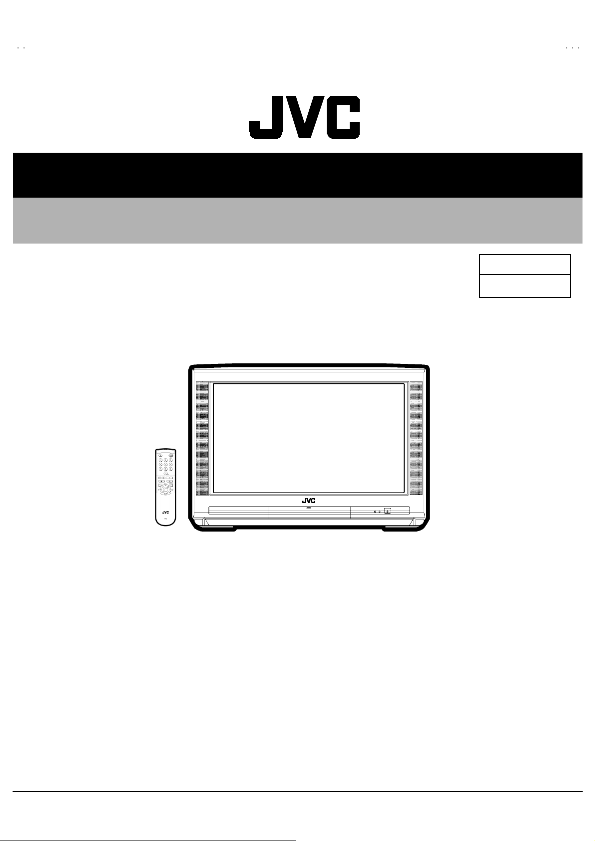
SERVICE MANUAL
COLOUR TELEVISION
AV28CH1 EUS
AV28 CH1 EU
BASIC CHASSIS
AV28CH1EUS
AV28CH1EUB
MF
CONTENTS
! SPECIFICATIONS ・・・・・・・・・・・・・・・・・・・・・・・・・・・・・・・・
!
SAFETY PRECAUTIONS
!
FEATURES・・・・・・・・・・・・・・・・・・・・・・・・・・・・・・・・
! MAIN DIFFERENCE LIST ・・・・・・・・・・・・・・・・・・・・・・・・・・・・・・・・
!
SPECIFIC SERVICE INSTRUCTIONS
! SERVICE ADJUSTMENTS ・・・・・・・・・・・・・・・・・・・・・・・・・・・・・・・・
!
PARTS LIST
★
STAND ARD CIRCUIT DIAGRAM
1
・・・・・・・・・・・・・・・・・・・・・・・・・・・・・・・・・・・・・・・・・・・・・・・・・・・・・・・・・・・・・・・・
・・・・・・・・・・・・・・・・・・・・・・・・・・・・・・・・・・・・・・・・・・・・・・・・・・・・・・・・・・・・・・・・
・・・・・・・・・・・・・・・・・・・・・・・・・・・・・・・・・・・・・・・・・・・・・・・・・・・・・・・・・・・・・
・・・・・・・・・・・・・・・・・・・・・・・・・・・・・・・・・・・・・・・・・・・・・・・・・・・・・・・・・・・・・・・・
・・・・・・・・・・・・・・・・・・・・・・・・・・・・・・・・
・・・・・・・・・・・・・・・・・・・・・・・・・・・・・・・・・・・・・・・・・・・・・・・・・・・・・・・
・・・・・・・・・・・・・・・・・・・・・・・・・・・・・・・・・・・・・・・・・・・・・・・・・・・・・・・・・・・・・・・・
・・・・・・・・・・・・・・・・・・・・・・・・・・・・・・・・・・・
・・・・・・・・・・・・・・・・・・・・・・・・・・・・・・・・・・・・・・・・・・・・・・・・・・・・・・・・・・・・・・・・
・・・・・・・・・・・・・・・・・・・・・・・・・・・・・・・・・・・・・・・・・・・・・・・・・・・・・・・
・・・・・・・・・・・・・・・・・・・・・・・・・・・・・・・・・・・・・・・・・・・・・・・・・・・・・・・・・・・・・・・・
・・・・・・・・・・・・・・・・・・・・・・・・・・・・・・・・
・・・・・・・・・・・・・・・・・・・・・・・・・・・・・・・・・・・・・・・・・・・・・
・・・・・・・・・・・・・・・・・・・・・・・・・・・・・・・・・・・・・・・・・・・・・・・・・・・・・・・・・・・・・・・・
・・・・・・・・・・・・・・・・・・・・・・・・・・・・・・・・・・・・・・・・・・・・・・・・・・・・・
・・・・・・・・・・・・・・・・・・・・・・・・・・・・・・・・・・・・・・・・・・・・・・・・・・・・・・・・・・・・・・・・
・・・・・・・・・・・・・・・・・・・・・・・・・・・・・・・・
・・・・・・・・・・・・・・・・・・・・・・・・・・・・・・・・・・・・・・・・・・・・・・・・・・・・・・・・・・・・・・・・
・・・・・・・・・・・・・・・・・・・・・・・・・・・・・・・・・・・・・・・・・・・・・・・・・・・・・・・・・・・・・・・・
・・・・・・・・・・・・・・・・・・・・・・・・・・・・・・・・
・・・・・・・・・・・・・・・・・・・・・・・・・・・・・・・・・・・・・・・・・・・・・・・・
・・・・・・・・・・・・・・・・・・・・・・・・・・・・・・・・・・・・・・・・・・・・・・・・・・・・・・・・・・・・・・・・
COPYRIGHT © 2002 VICTOR COMPANY OF JAPAN, LTD.
・・・・・・・・・・・・・・・・・・・・・・・・・・・・・ 2
・・・・・・・・・・・・・・・・・・・・・・・・・・・・・・・・・・・・・・・・・・・・・・・・・・・・・・・・・・
・・・・・・・・・・・・・・・・・・・・・・・・・・・・・・・・・・・・
・・・・・・・・・・・・・・・・・・・・・・・・・・・・・・・・・・・・・・・・・・・・・・・・・・・・・・・・・・・・・・・・
・・・・・・・・・・・・・・・・・・・・・・・
・・・・・・・・・・・・・・・・・・・・・・・・・・・・・・・・・・・・・・・・・・・・・・
・・・ 5
・・・・・・
・・・・・・・・・・・・・・・・・・・・・・・ 5
・・・・・・・・・・・・・・・・・・・・・・・・・・・・・・・・・・・・・・・・・・・・・・
・・・・・・・・・・・・・
・・・・・・・・・・・・・・・・・・・・・・・・・・
・・・・・・・・・・・・・・・・・・・・・ 12
・・・・・・・・・・・・・・・・・・・・・・・・・・・・・・・・・・・・・・・・・・
31
・・・・・・・・・・・・・・・・
・・・・・・・・・・・・・・・・・・・・・・・・・・・・・・・・
2- 1
4
6
No.519 44
Mar. 2002
Page 2
A
V28CH1EUS
A
y
V28CH1EUB
SPECIFICATIONS
Item
Dimensions ( W××××H××××D ) 72 5mm×4 80m m×496mm
Mass 34 .7 kg
TV RF System
Colour Sy stem PA L / SECA M / NT SC (Only i n EXT mode)
Stere o Sy st em A2 (B /G,D/K)/ NICAM(B/G,I ,D/K,L)
Teletext System FLOF (Fastext)
Receiving Frequency
Interme diate Fr equenc
VIF Carrier 38 .9 MHz ( B/G , I ,L)/ 3 3.9 5 MHz (L’)
SIF Carrier 33 .4 MHz ( 5.5MHz :B/ G) / 32.9MHz (6.0 MHz:I ) / 32.4MHz (6.5MHz:L , D/K) / 40 .45MHz (6.5MHz:L’ )
Colour Sub Carrier Fr eq.
SE CAM 4.40625MHz/4.25MHz
Power Input AC 2 30V , 50Hz
Power Consumpti on
CCIR (B/G,D/K, I ,L, L ’)
TOP (German syst em)
WST(W orld Standard system)
VHF 47 MHz ~ 47 0MHz
UHF
470MHz ~ 8 62MHz
PAL 4.43MHz
NT S C 3.58MHz / 4.43MHz
16 5W ( Max) / 112W(Avg) , sta ndby : 2.8W
AV28CH1EUS / AV28CH1EUB
Content
Aerial Input Term
Pictur e Tube
Hi gh Vo lt ag e
Speake r
Au dio Output 5W + 5W
EX T-1 /EXT-2/EXT- 3
(Input / Output)
S / Video
EXT-4 (Input) Video
Au di o (L /R )
S / Video
AUDIO OUT (Vari able)
Headphone jack St ereo mi n i jac k (φ3.5mm )
Remote Control Unit RM-C 54 H (AAA/R 0 3 dr y batte ry×2) : (A V2 8CH1EUS) / R M-C50( AAA/R03 d r y bat tery×2 ) : (A V2 8CH1EUB)
75 Ωun ba l anc ed, C oaxi al
Visi ble si ze : 66 cm, Meas ured di a gon al l y
1kV
+
30.0kV (at zero beam current)
-1. 5kV
(10c m×3cm) ov al typ e ×2
21 -pin E ur o c onnec to r
(SCART socket)
p-p
Y : 1V
C : 0.3V
1V p- p 7 5Ω(RCA pi n jack)
50 0mVr ms( -4dB s ), H igh Impe dan ce ( RCA pin jack )
Y : 1V
C : 0.3V
0~1 Vrms, Low Imp ed ance
(RCA pi n jack ×2)
POSITIVE (Negative sync Provided, when terminated with 75Ω)
p-p
(Burst signal, when terminated with 75Ω)
p-p
POSITIVE (Negative sync Provided, when terminated with 75Ω)
p-p
(Burst signal, when terminated with 75Ω)
De sign & sp eci ficatio ns ar e su bje ct to change wi thou t no t ice .
2
No.51944
Page 3
A
V28CH1EUS
A
V28CH1EUB
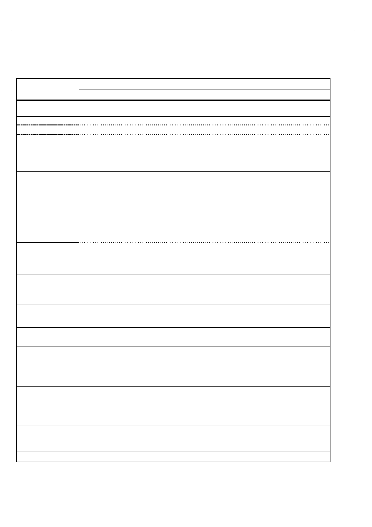
■■■■21-pin Euro connector (SCART socket) : EXT-1 / EXT-2 / EXT-3
(P-P= Peak to Peak, B-W= Blanking to white peak)
Pin
Signal Designation Matching Value EXT-1 EXT-2 EXT-3
No .
1 AUDIO R o ut put 50 0mVr ms( N ominal),
Low impedance
2 AUDIO R input 50 0mVr ms( N ominal),
High i m pe da nce
3 AUDIO L o utput 50 0mVr ms( N ominal),
Low impedance
4 AUDIO GN D ○○○
5 GND (B)
6 AUDIO L input 500mVrms(Nominal),
High i m pe da nce
7B input 700mV
8 FUNCTION SW
(SLOW SW)
9 GND (G)
10 SCL3 NC ○ NC
11 G in put 70 0m V
12 SDA3 NC ○ NC
13 GND (R)
14 GND (YS) ○ NC NC
15 R / C input R : 700mV
16 Ys i n put
17 GND(VIDEO output) ○○○
18 GND(VIDEO input) ○○○
19 VID EO output 1V
20 VIDEO / Y inp ut 1V
21 COMMON GN D ○○○
Low : 0-3V, High : 8-12V, High
impedance
C : 300mV
Low : 0 - 0.4, High : 1 - 3V, 75Ω○
, 75Ω○○NC
B- W
, 75Ω○○NC
B- W
, 75Ω
B- W
, 75Ω
P- P
(Nega tiv e g oin g sync ), 75Ω○
P- P
(Nega tiv e g oin g sync ), 75Ω○ ○ ○
P- P
○
(TV OUT)
○○○
○
(TV OUT)
○○○
○○○
○○○
○○○
○○○
○
(only R)
(TV)
○
(LINE OUT)
○
(LINE OUT)
○
NC NC
○
(LINE OUT)
NC
NC
○
(only C)
NC
[Pin assignment]
No.51944
3
Page 4
A
V28CH1EUS
A
V28CH1EUB
SAFETY PRECAUTIONS
1. T he design of th is pr od uc t con ta in s sp eci al hard ware, many
circuit s and components specially for safety purposes. For
con tinu ed pr ot ection , n o chan g es sh ou ld b e ma de to the o ri g inal
d esi gn un l ess auth oriz ed in writi n g by th e ma nu fact urer.
Replac em en t p arts m ust be ident ic al to thos e u sed in th e or i ginal
ci rcu it s. Serv ice s ho uld b e p er for m ed by qu al if i ed p ers on nel
on ly.
2. Alte r ati on s of the design or ci r cui try of t he prod ucts sh ould not be
made. Any design alterations or additions will void the
manufact ur er 's warrant y and will f urth er r eliev e t he ma nu factu r er
of r esp onsi b ility for per so na l injur y or p r op er ty d am ag e r esult ing
th erefr om.
3. M an y e lectric al and mech ani ca l parts i n th e prod ucts ha ve
special safety-related characteristics. These characteristics are
oft en no t e v ident f r om v isua l i nsp ection n or ca n t he pr o tec t io n
aff or de d by th em nece ssar i l y be ob tain ed b y u sin g r ep l acement
com po ne nts ra ted f or hig he r vol tage, watt ag e, etc. R ep l acem en t
p arts whic h ha ve th ese sp eci al s afet y ch ar ac t er ist ics are
ide ntified i n the parts list of Servic e manua l. El ec tric al
components having such features are identi fied by shading
on t he sche mat ic s an d by (
manual. The us e of a sub s ti tu te rep lacem en t whi ch does n ot
h ave th e same saf ety ch ar act er ist ics as t he r eco mmen de d
replac em ent part sh own i n th e p ar ts lis t of S er vic e man ual may
cause shock, fire, or other hazards .
!!!!
) on the parts list in Service
4. Don't shor t between the LIVE side ground and ISOLATED
(NE UTRAL) side ground or EARTH side ground when
repairing.
Some model's power circuit is partly different in the GND. The
diff er enc e of th e GND i s s ho wn b y th e LIV E : (") side GND , the
ISO LATED(NEUT RAL) : (#) si de GND and EAR T H : ($) side
GND. Don't sh ort b et ween th e LIV E sid e GN D and
ISO LATED(NEUT RAL) side GND or EARTH side GND an d
n ever m ea s ur e w it h a m ea suring a ppa r atus ( osc illos cop e etc.)
th e LI VE si d e GND an d IS OLA TED (NE UTR AL ) s ide G ND or
EARTH side GND at th e s ame time.
If above note will not be kept, a fuse or any parts will be broken.
5. If any repair has been made to the chassis, it is recommended
th at t he B1 set ti ng s hou l d b e ch eck e d or adju ste d ( Se e
ADJUST MENT OF B1 POWE R SUPPL Y) .
6. The hi gh v olta ge app li e d t o th e pictu re tu be mu st confor m with
th at s p ecified in S ervi ce manual. E xcessi ve high volt ag e c a n
cau s e an i ncr e ase i n X- R ay em i ssi on , ar c ing an d possi b le
component damage, therefore operation under excessive high
voltage conditions should be kept to a minimum, or should be
preve nt ed. If s ever e arc ing occ ur s, r emove t he AC pow er
immed i ate ly an d de ter m i ne th e c a use b y visua l insp ec t io n
(inc or rect ins tal lat i on, cracke d or melte d high vo ltage har n ess,
p oor so lder i ng, et c.). To maint ai n the p roper min im u m le vel of
sof t X- R ay emi ssi on, c omp on en ts i n th e hi gh v oltag e cir c uitr y
incl ud ing t he pi ct ur e tu be must be t he e xact r ep l aceme nts or
alte rn at i ves ap pr ove d b y th e ma nuf act urer of th e c om pl et e
product.
7. Do not c hec k high volt age b y dr awing an ar c. Us e a high vol t age
meter or a hi g h v oltag e pr ob e wit h a V TVM. Discharge th e
picture tube before attempting meter connection, by connecting
a cl i p lead to th e gr ou nd f ra me and c onn ectin g th e other end of
the lead through a 10kΩ 2W resi sto r to the anod e b utt on .
8. When se rvice i s require d, ob ser ve th e or i gina l lea d dress. E x tr a
prec aut ion sh ou ld b e g iven t o ass ur e corr ec t l ea d dr ess i n the
high vol tag e c ircui t a r ea. W her e a s hort ci r cuit h as oc cu rre d,
th ose co mp on ent s tha t i ndi ca te evide nce of ove r hea ting sho ul d
b e r e pl ace d. A l wa ys u se th e ma nuf act urer's r ep l acem en t
components.
9. Isolation Check
(1) Dielectric Strength Test
(2) Leakage Current Check
(Safety for Electrical Shock Hazard)
Af ter re- ass emb l in g th e pr odu c t, al w ays per f orm an i sol at ion
ch ec k on the expo sed metal parts of t he c abin et ( a ntenn a
ter m inals, video /audio inpu t and ou tput t erminals , C on trol kn obs,
metal cabi n et, scr ew he ad s, ea r ph one j ack, con trol s haf ts, etc.)
to be s u re th e p roduct is s af e t o ope r ate with ou t dan ger of
elect ri cal s hoc k.
The iso l ati on be tween the AC pr imary ci rcuit an d all metal parts
exp osed t o th e us er , p arti cular l y any e xp os ed met al p art having a
retu rn p ath to t he chass is sho uld withs tan d a vol t age of 3 000 V
AC (r.m. s.) for a period of one second.
(. . . . W it hs tan d a v o lt ag e of 1 10 0V A C (r.m. s.) t o an applianc e
rate d up to 12 0V , an d 3 00 0V AC ( r .m. s.) to an ap pl ian ce r at ed
200V or more, for a period of one second.)
This meth od of test requi res a t est equ ipment n ot g enerally found
in t he servic e trad e.
Plug th e A C line c ord d irect ly into th e AC ou tlet ( d o not use a line
isol ati o n tr ansf or m er du r in g thi s ch eck.). Usi n g a " Lea kage
Curr ent T este r", me asur e th e lea kag e cu rre nt f rom each exp osed
metal p art of the cabinet, p art icu larly any expos ed me tal p ar t
h avi ng a re tur n path to the c h assis , t o a kn own go od ea rt h
ground (water pip e, e tc.) . An y l eaka ge curren t m ust n ot e xceed
0.5mA AC (r.m.s.).
Howev e r, i n tr op ic al area , th is must no t exce ed 0.2 mA AC
(r.m.s.).
""""
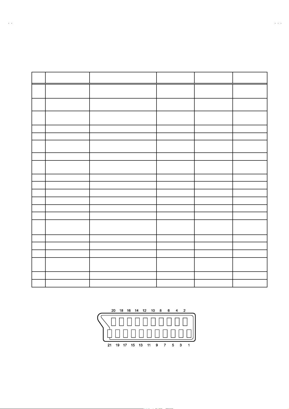
Alternate Che ck M et hod
Plug th e A C line c ord d irect ly into th e AC ou tlet ( d o not use a line
isol ati o n tr an s for m er dur ing t hi s che c k.). U se an AC vo lt me ter
h avi ng 1 00 0 ohms pe r volt or mor e s ens itivi ty in th e fo ll owing
manner. Con nec t a 1 50 0Ω 10W res ist or par a lle led by a 0 .1 5µF
AC-type c apa cit or bet ween an expo sed met al pa rt a nd a known
g ood e ar th gro un d (water pipe , etc.). M eas ure th e A C volt ag e
acr oss th e res ist or w ith th e AC vo ltm eter . Move th e r esis tor
con nec ti on to each exp ose d metal part, part ic ularly a ny exp os ed
metal p art havin g a retu rn pat h to t he ch as sis , an d m easu re th e
AC vol tag e ac ro ss the res ist or . No w, re vers e th e pl u g i n th e AC
ou tl et and re pe at eac h mea s ur emen t. Any volt ag e me asured
must no t e xceed 0 .75V AC (r.m. s.). This c orre spo nds to 0.5mA
AC (r.m. s.).
Howeve r, in tropica l are a, this must n ot exceed 0.3V AC ( r.m.s.).
This corresponds to 0.2mA AC (r.m.s.).
AC VOLT MET ER
(HAVING 1000 Ω /V,
OR MOR E SENSIT IVITY)
0.15μF AC-T YPE
PLACE THIS PROBE
1500 Ω 10W
GOOD EARTH GROUND
ON E A C H EX PO SE D
ME T AL PA RT
4
No.51944
Page 5
A
A
FEATURES
V28CH1EUS
V28CH1EUB
"
New c hass is d es ign ena bl e us e of an i nte rac ti ve on screen
control.
"
The TELETEXT SYSTEM has a built-in FASTEXT (UK syst em),
TOP (Germ an syst em) and W ST (world standard system)
system.
"
Be c aus e th is T V un i t cor r esp on ds t o m ultiple x br oa dc a st, u s ers
can enjoy music programs and sporting events with live realism.
In ad di ti on , BI LIN GUAL programs can b e h ear d in th eir or i g in al
language.
TV EXT-1 EXT-3
EXT-2
"
Users can make VCR dubbing of picture and sound by controlling
th e AV s elec tor to se lec t an optiona l so urc e at th e EXT- 2 outp ut
sh own i n fi gu re.
EXT-4
MAIN DIFFERENCE LIST
Model Name
!
Par t Name
!
FRONT CABINE T ASSY LC 10001- 008C- U LC 1000 1-00 9B-U
!
DOOR LC 20 00 1-01 0A-U LC 20 00 1-01 2A-U
!
POWER KNOB LC 30 10 4- 01 0A -U LC 30 10 4- 01 2A -U
RE A R COVER LC 10 03 -0 09 B- U LC 10 00 3- 01 0B -U
!
JV C MA RK LC 40 35 4- 00 3A -U LC 40 35 4- 00 1C-U
!
RATING L ABEL
LC 114 14 -001A -U
EURO LABEL AEM1064-009-E AEM1064-010-E
REMOTE CONTROL UNIT RM-C54H-1C RM-C50-1C
AV28CH1EUS AV28CH1EUB
LC 114 14 -002A -U
No.51944
5
Page 6
A
V28CH1EUS
A
V28CH1EUB
SPECIFIC SERVICE INSTRUCTIONS
DISASSEMBLY PROCEDURE
REMOVING THE REAR COVER
1. Unplug t he po wer c or d.
2. Remove the 14 screws marked
3. Withdra w t he r ear cover to wa rd you .
REMOVING THE CHASSIS
"
After removing the rear cover.
1. Sl i ght ly r aise the bo th side s of th e c hass is by h and and re mo ve
th e tw o claws u nd er th e both sid es of the ch assis fr om t he fro nt
cab inet .
2. Withdra w t he chass is back wa rd .
(If necessary, take off the wire clamp, co nnectors etc.)
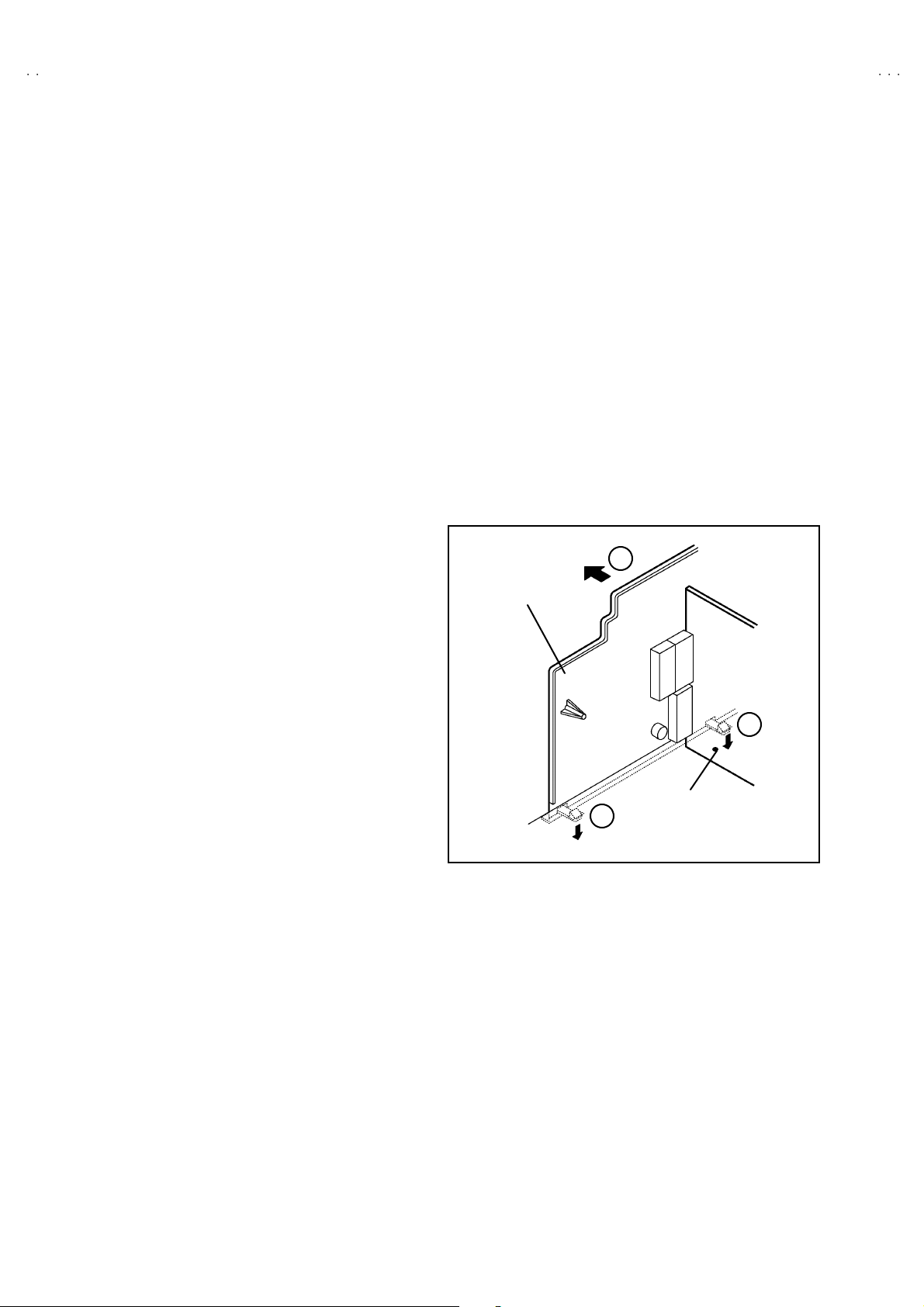
REMOVING THE AV TERMINAL BOARD
" After removing the rear cover.
1. Remov e th e 2 s cr ews m ar ked
2. Remove the claws marked
Fig. 2.
3. Slight ly in t he di re ction of ar r ow
####
as sh own in th e Fig. 1.
!!!!
as sh own in th e Fig. 1.
""""
un der t he CHAS SIS as sho wn in
as sh own in Fi g. 2.
$$$$
D
AV TERMINAL
BOARD
REMOVING THE SPEAKER
" After removing the rear cover.
1. Remov e t he 2 s cr ews m ar ked
2. F ollow th e s ame st eps when removi ng th e other ha nd speake r.
as sh own in Fi g. 1.
%%%%
CHECKING THE PW BOARD
To c h eck the b ack side of th e PW B oard.
1) Pu ll out the chassis. (R efer to RE MOV ING THE CHAS SIS ).
2) Erect the chassis vertically so that you c an easily check the
b ack si de of th e PW B oard.
[CAUTION]
"
When erecting the chassis, be careful s o that there will be no
contacting with other PW Board.
"
Be for e turning on po wer, ma ke s ur e t ha t the wi re co nn ector is
properly connec ted.
"
W hen condu cting a ch eck w ith p ow er su pplied , b e sure to c onfi r m
th at t he CRT E ART H WI RE (B RA ID ED AS S’Y) is co nne cted t o
th e C RT SOCKE T PW b oar d.
WIRE CLAMPING AND CABLE TYING
1. Be sure to cla mp th e wire.
2. Never r emo ve th e c able tie use d f or ty ing th e wires to gether.
Sh ould i t be i n adve rt ent l y remov e d, b e su re to ti e th e wires w it h
a n ew c able ti e.
C
AV SE L PWB
C
Fig . 2
6
No.51944
Page 7
A
A
FRONT CABINET
S
CRT
SOCKET
PWB
FRONT
C ONT RO L
PWB
MICON PWB
10 0Hz PW B
V28CH1EUS
V28CH1EUB
PEAKER
E
POWER & DEF. PWB
C ONT RO L BASE
REAR COVER
MAIN PWB
CLAW
AV SW PWB
CLAW
FBT
CHASSIS
AV TERMINAL
BOARD
B
A
Fig . 1
No.51944
7
Page 8
A
V28CH1EUS
A
V28CH1EUB
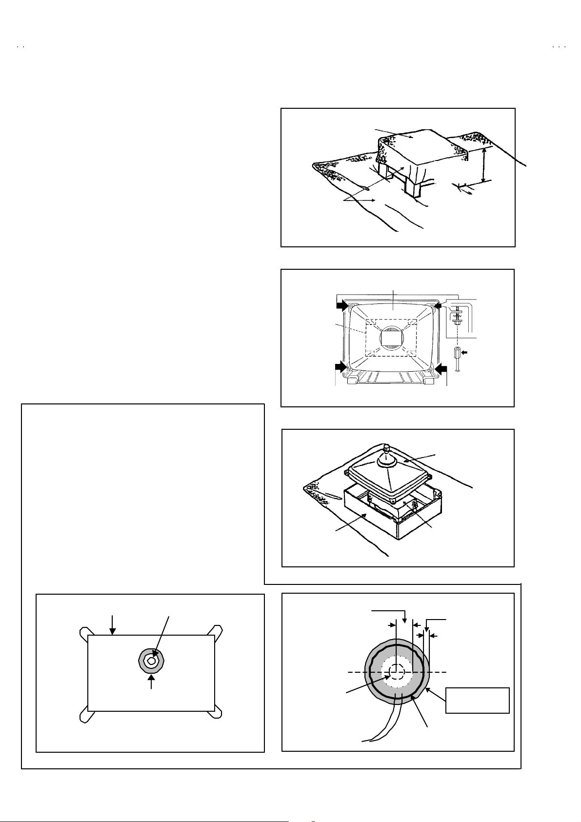
REMOVING THE CRT
∗
Replac em en t of th e CRT sho uld be p er for m ed by 2 or more
p ers ons.
• After removing the cover, chassis etc.,
1. Putti ng th e CR T c hange tabl e o n sof t cloth , the CRT chang e ta ble
sh ould al so b e c over ed w ith s uch soft clot h (sho wn in Fi g. 3).
2. W hile kee pin g th e surf ac e of CRT down , m ou nt the TV s et on t he
CRT change table balanced will as shown in Fig.4.
3. R em ove 4 sc re ws mar ke d by arro ws with a b ox typ e scr e w driver
as s hown in Fig. 4.
• Si nc e the cab inet will dr op wh en scr ew s h ave b een remo ved, be
sure t o su pport t he cab inet with hands.
4. After 4 screws have been removed, put the cabinet slowly on
cloth (At this time, be ca refully so as not to damage the front
sur fac e of th e c abin et) sh own in Fig.5 .
• The CRT s h oul d b e ass em bl ed accor di n g to the o pp osite
sequence of its dismounting steps.
∗
The CRT cha ng e t able sh ould pref er ab l y be sm al ler t hat the CRT
sur fac e, and its height b e about 35c m.
CRT CHANGE TABL E
AP PROX.
35 cm
CLOTH
Fig. 3
CRT
CRT
CHANGE
TABLE
BOX
TYPE
SCREW
DRI VER
COATING OF SILICON GREASE FOR ELECTRICAL
INSULATION ON THE CRT ANODE CAP SECTION.
•
Su bs e qu ent to re pl ac ement of t he C RT an d HV tr an sfor m er o r
repair of t he an od e ca p, etc. by dis mount i ng the m, be sure to c oa t
si lic o n g re ase fo r el ectric al insu latio n as sh ow n in Fig .6.
W ipe a roun d t he an ode b utton with cl ea n and dr y cl ot h. (F ig. 6)
Coat si l ic on greas e on t he sect ion arou nd th e a no de bu tt on. At
this time, take care so t hat any silicon greases dose not stick to
the ano de button . (F ig.7 )
★★★★
Sil icon grease product No. KS - 650N
CRT
An od e b utton
Silic on greas e
coating
CABINET
Ap prox.
20mm (Do not
coat grease on
this section
An od e b utton
(No s ti cki ng of
silicon grease)
Fig. 4
CRT
CRT
CHANGE TA BLE
Fig. 5
Silic on greas e
sh oul d be coa ted
b y 5mm or m ore
fr om th e outs id e
diameter of
an od e c ap.
Coat ing posi t io n
of silico n gr eas e
An od e ca p
Fig. 6 Fig. 7
8
No. 51944
Page 9
A
A
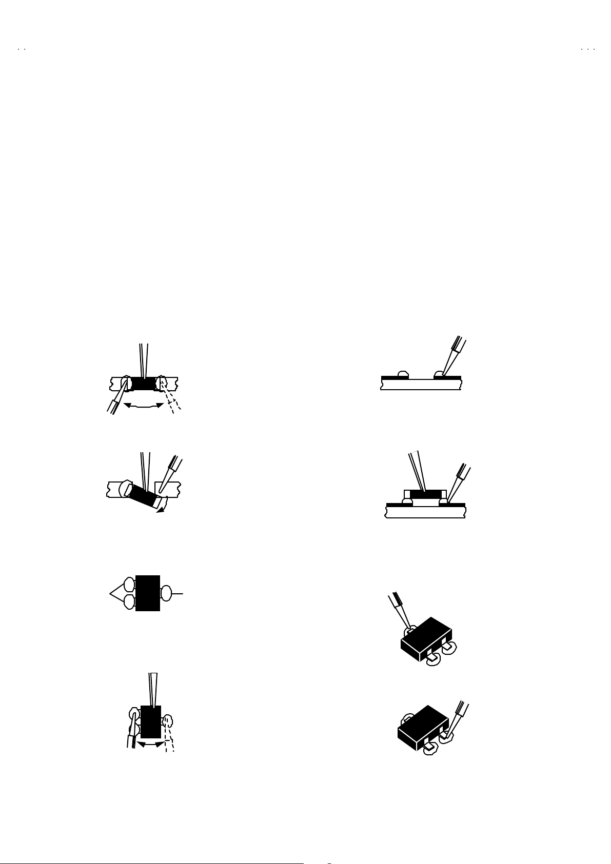
REPLACEMENT OF CHIP COMPONENT
! CAUTIONS
1. Avoid heating for more than 3 seconds.
2. Do n ot rub t he elect rodes an d t he r esis t p ar ts of the patt ern.
3. When r emovi ng a c hip part, mel t th e s older ad equate ly.
4. Do n ot reuse a chip part after removi ng it .
! SOLDERING IRON
1. Us e a hi g h i ns ulati o n solder ing iron with a t hi n po in ted end of it.
2. A 3 0 w s older ing iron is rec omm end ed for easil y remov ing p ar ts .
!
REPLACEMENT STEPS
1. How to remove Chip parts
####
Resi st ors, ca pacit ors , etc
(1) As s h own in t he f ig ur e, pu s h th e pa rt with tw ee zers and
alte rn at el y melt th e s older at each en d.
(2) Sh if t w ith tw eeze rs and r em o ve th e ch ip p ar t.
#### T ran s ist ors, diodes , varia bl e resist or s, etc
(1) Ap ply e xt ra solder to ea ch le ad.
SOLDE R SOLDE R
V28CH1EUS
V28CH1EUB
2. How to install Chip parts
####
Resi st ors, ca pa cit ors , etc
(1) Apply solder to th e patter n as ind icated in the figure.
(2) Gr asp t he ch ip p art with tw ee zers and pl ac e it on th e s old er.
The n hea t and melt th e so lder a t b oth en ds of t he chip part.
#### T ran s istors, dio des, va ria bl e r esistors, et c
(1) Apply solder to th e patter n as ind icated in the figure.
(2) Gr asp th e chip part with t we ezers an d pl ace it on th e solder.
(3) First solder lead A as indicated in the figure.
A
(2) As s h own in t he f ig ur e, pu s h th e pa rt with tw ee zers and
alte rn at el y melt th e sold er a t each l e ad . Shift an d r em ove t he
chip part.
(4) The n so lder le ads B and C.
Note : A fte r re movin g t he part , remove remain ing so lder from the
pattern.
C
A
C
No.51944
B
B
9
Page 10
A
V28CH1EUS
A
V28CH1EUB
REPLACEMENT OF MEMORY ICs
1. Memory ICs
This TV use memory ICs. In the memory ICs, there are memorized data
for cor r ectl y op erating th e video an d def l ection cir cu its . Wh en r ep l aci ng
memory IC s, b e s ure t o us e IC s wri tte n with th e initial values of da ta.
2. Procedure for replacing memory ICs
PROCEDURE
(1) Power of f
Switch the p ower of f and un plug th e pow er cor d fro m t he ou tlet.
(2) R epla ce IC s.
Be sure to use memory ICs written with the initial data values.
(3) Powe r on
Plug th e p ower c ord i nt o the outlet a nd swit ch t he po we r on .
(4) Check and s et SY STEM CO NSTANT SET :
****
It must not adjust without sig na l.
1) Pr ess th e INFORMAT I ON ke y an d th e MU TING key of th e
REMO TE CONTROL UNIT simultaneous ly.
2) The SERVICE MENU screen of Fig. 1 will be displayed.
3) W hi le th e S ERVIC E ME NU is d is played, pr es s th e
INFORMATION key and MUTING key s imultaneously, and the
SYSTEM CONSTANT SET screen of Fig. 2 will be displayed.
4) Check th e se tting va lues of the S YSTEM C ON ST A NT SET of
Table 1. If the value is d if fere nt, se lect the s ettin g item with th e
FUNCTION U P/ DOWN key, and s et the correct va lue with the
FUNCTION - /+ ke y.
5) Press the MENU key to memorize the setting value.
6) Pr ess t he IN FORMATION ke y t wice, a nd r etu rn t o th e normal
screen.
SE RV ICE MEN U
1. IF 2. V/C
3. A UDI O 4. D EF
5. VSM P RESET 6. S TATUS
7. P IP 8. ---
9. SHIPPING (OFF) 0. BUS FREE
1 -9 : SE LE CT
SY STE M CON ST ANT S ET
1. DESTINATION EU
- /+ : STORE i : EXIT
OK
Fig.1
Fig.2
i
: EXI T
NAME OF REMOTE CONTROL KEY
(5) Se tt in g of re cei ve chann e ls
Names of key
ke y
Se t the rec eive c h an ne l.
For setting , ref er to the OPE RATING IN S TRUC TIONS.
(6) U ser se tting s
INFORMATI ON
MU T I N G
iiii
Check th e us er sett in g values of Tab le 2, and i f sett in g value is
diff er ent , set the c orr ec t val u e.
For setting , ref er to the OPE RATING IN S TRUC TIONS.
(7) Setting of SERVICE MENU
Ve rif y the set ti ng it ems of th e SER VIC E ME NU of Tab le 3, an d rese t
ME NU
FUNCTION UP/ DO WN
OK
▼
▼
where n ecessary.
For setting , ref er to the SE RVICE ADJUSTM ENT S.
FUNCTION -/+
▼
▼
10
No. 51944
Page 11
A
A
SETT I NG VALU ES OF SYST EM CONS TANT SE T (TABLE 1)
V28CH1EUS
V28CH1EUB
Setting item Setting content Setting value
16 :9
NO
NO
EKEU EI
4:3
YE SNO
YE SNO
YE S
2TUNER1TUNER
YE S
DESTIN A TION EU DOLBY NO
CRT TYPE 16:9 BB E NO
PURITY NO PROGRESSIVE NO
PICTURE TILT NO TDA9178 NO
DIGIP URE PRO NO TONE IC NO
PIP NO F LAT NO
PIC&TE XT NO
NO
Setting item
Setting content Setting value
YE SNO
YE SNO
YE SNO
NO
NO
YE S
YE SNO
YE S
USER SETTING VALUES (TABLE 2)
PICTURE SE TTING EX T SET TI NG
TINT COOL
CONTRAST / BRIGH T
SHAR P / COLO UR
PICTURE FEATURES FEATURES
DIGITAL VNR AUTO
Digipure PRO AUTO
COLO UR S YST E M TV : Acco rd in g t o pr eset C H
4:3 AUT O ASPE CT PA NO RAMIC
SOUND SET TING INSTALL
BA SS / TREBL E / BA LANCE LANGUAGE ENGLISH
HYPER SOUND OFF EDIT/MANUAL PRESET CH only
REFER to VSM PRESET
EXT : AUTO
CENTER
ID
S-IN
DUBBING
SLEEP TIMER
BLUE BA CK
BLANK
BLANK
EXT- 1→EX T-2
OFF
ON
The others : BLANK
SERVICE MENU SETING IT EMS (TAB LE 3)
Setting item Setting value Setting item Setting value
1. IF 1. VCO
2. ATT ON /OFF
2. V / C 1. RGB BLK
3.A UD IO
(Do not adjust)
9.S HIPPI NG
(Do not adjust)
2. W D R R
3. W D R G
4. W D R B
5. BRIGHT
6. CONTRAST
7. COLO UR
8. HUE
9. SHAR P
10. VC O A DJ .
1. ER R LI MIT
2. A2 ID THR
ON/OFF
4. DE F. 1. V- SH IF T
5. VSM PRESET
COOL
NORMA L
WARM
6.S TATUS
(Do not a dju st)
No. 51944
2. V-SIZE
3. H-CENT
4. H-S IZE
5. TR APE Z
6. EW - PIN
7. COR-P IN
8. COR-UP
9. COR-LO
10. ANGLE
11 . BOW
12. V-S.CR
13 . V- LIN
1. CONT.
2. BRIGHT
3. SHAR P
4. COLO UR
5. HUE
6. W D R R
7. W D R G
8. W D R B
VP S
PDC
11
Page 12

A
V28CH1EUS
A
V28CH1EUB
SERVICE ADJUSTMENTS
BEFORE STARTING SERVICE ADJUSTMENT
1. There ar e 2 w ays o f adjusting this T V: On e is wi th t he
REMOTE CONTROL UNI T and the other is the conventional
method using adjustment parts and components.
2. The setting (adjustment) us ing the REMOTE CONTROL
UNIT is made on the basis of th e init ial setting values. The
se tting va lues which adj u st the scree n to t h e opt imum
condition can be different from the initial setting values.
3. M ak e s ure th at c onn ect i on is c orrect ly ma de t o AC p ow er
source.
4. T ur n on th e pow e r of th e TV a nd m easu ring ins tr um en t for
warmi n g u p for at l east 30 minut es b ef ore sta rt ing adju stment .
5. If th e r ec eive or i np ut si g nal is not speci fi ed , use t he m ost
ap prop riate s igna l f or a dj ust ment.
6. N ever tou ch parts ( s uch as variab le res ist ors, transform er s an d
condensers) not shown in the adjustment items of this service
adjustment.
7. Prep ar ati o n f or ad j ustmen t ( pr es ettin g) :
Unles s oth er wis e speci fi ed i n the a djust ment it em s, p r eset th e
follo win g funct ions with th e REMOTE CONTROL UNI T.
"
Setti ng posit ion
PICTURE MODE (VSM) NORMAL
SLEEP TIMER OFF
TONE BALAN CE CENTER
ZOOM PANORAMIC
MEASURING INSTRUMENT AND FIXTURES
1. DC voltmeter (or digital voltmeter)
2. Oscilloscope
3. Si gn al gener at or (Patt ern gener at or) [ PAL / SE CA M / NT SC]
4. Remote control unit
ADJUSTMENT ITEMS
●
Check ing i t ems.
●
Adjustment of FOC US & SCREEN
●
VS M p r eset ad ju st s ettin g.
●
VIDEO / CHROMA circ uit adjustment.
●
DEFLECTION c ircuit adjustment.
●
AUDIO circuit adjustment. (Do not adjust)
12
No. 51944
Page 13

A
A
ADJUSTMENT LOCATIONS
(
)
5
V28CH1EUS
V28CH1EUB
FRON T
FRONT CONTROL PWB
F90 1
PW
POWER SW
CN001
FRON T
MAIN PWB POWER&DEF PWB
CN002
AV SEL PWB
CN006
IC702
MEMORY
100Hz PWB
IC701
F
SP R
SP L
FRON T
W DEG
TUNER
CRT SOCKET PWB
T P- 47R
T P- 47G
CN013
TP-E
MIC OM PWB
CN008
SOLDER SIDE
T P- 47B
CN009
TOP
E1
CN014
HV
HVT
FOCUS1
FOCUS2
SCREEN
X
1
1pin:B1( TP-91)
2pin:NC
3pin:NC
4pin:NC
5pin:GN D
No. 51944
13
Page 14

A
V28CH1EUS
A
y
y
V28CH1EUB
BASIC OPERATION SERVICE MENU
1. TOOL OF SERVICE MENU OPERATION
Operate the SERVICE MENU with the REMOTE CONTROL UNIT.
2. SE RVICE MENU ITEMS
With the SERVI CE M EN U, var i ou s sett in gs ( ad jus tm en ts) c an b e m ade , a nd th ey a re b r oad l y c lass if ied in th e f ol l owing items of s et tings
(adjus tm ents ):
(1) 1. IF ・・・・・・・ ・・・・・・・・・・・・・ ・・・ This m ode adjust s the se tting values of the IF circui t.
(2) 2.V /C ・・・・・・・ ・・・・・・・・・・・・・ ・・ T his m ode adjusts th e setting valu es o f th e VIDEO / CHROMA ci rcuit.
(3) 3.AUDIO・・・・・・・ ・・・・・・・・・・・・ This mode adjusts the setting values of the multiplic ity SOUND circuit.
(4) 4. DEF ・・・・・・・ ・・・・・・・・・・・・・ ・ This m od e adjust s th e setti ng values o f the DE FLECT ION c ircui t f or eac h as pect m od e g i ven be low.
FULL (100/120Hzi)
PA NO RA MIC ( 1 00 /12 0 H z i )
SUBTITLE (100/120Hzi)
COMP RESS (Fix ed val u e) (100/1 20H zi)
(5) 5.V SM PRESE T
(VSM : Video Status Memory)
3. BASIC OPERATION OF SERVICE MENU
(1) Ho w to enter SERVICE MENU
Press the INFORMATION key a nd the MUTING key of t he
REMO TE CONT RO L U NI T si mu lt an eou s ly, an d th e
SERVICE MENU screen of Fig. 1 will be displa yed.
(2) Selection of SUB MENU SCREEN
Press one of keys 1~5 of the REMOTE CO NTROL UNIT
an d sel e c t th e S UB M ENU SCR EEN ( See Fi g. 3 ), fo rm th e
SERVICE MENU.
SERVICE MENU → SUB MENU
・・・・・・・ ・・・・・・
1. IF
2. V / C
3. AUDIO
4. DE F.
5. VS M PRESE T
6. STATUS
7. PI P
8. ---
9. SHIPPING(OFF)
0. BUS FREE
Thi s mode adjust s th e in itial s ett ing va lues of COOL, N ORM AL an d WAR M .
SE RVICE M ENU
SE RV ICE MEN U
1. IF 2. V/ C
3. AU DIO 4. DE F
5. VS M PRESET 6. ST ATUS
7. PI P 8. -- -
9. SH IPPING ( OFF) 0. BU S FREE
1 -9 : SE LE CTi : EXI T
Fig.1
NEME OF REMOTE CONTOROL KEY
Names of ke
INFORMATI ON
MU T I N G
ME NU
Do no t W o rk
FUNCTION UP/ DO WN
FUNCTION -/+
Fig.2
ke
iiii
OK
▼
▼
▼
▼
14
No. 51944
Page 15

A
A
SERVICE MENU
SERVICE ME NU
1. I F 2. V /C
3. AUDIO 4. DEF
5. VSM PR ESET 6. STAT US
7. PIP (OFF) 8. - - -
9. SHIPPING (O FF) 0. BUS FREE
1-9 : SELE CT : EX ITi
V28CH1EUS
V28CH1EUB
1. V- SH I F T
2. V- SI Z E
3. H-CENT
4. H-SIZE
5. TRAPEZ
6. EW -PIN
7. COR PIN
8. COR-UP
9. COR-LO
10. A NGLE
11. B OW
12.V- S.CR
13.V-LIN
DE F *** Hz FUL L
1. V- SHI F T
: STORE i : EXIT
OK
- / +
4. DEF
***
1.IF(VCO)
IF SER VICE M E NU
1. VCO
2. ATT O N/O FF
1-2 : SELECT i : EXIT
2. V/C
V/C
PAL
1. RGB_BLK
- / +
: STORE i : EXIT
OK
****
Do no t move
1. RGB BL K
2. WDR R
3. WDR G
4. WDR B
5. BRIGHT
6. CONT RAST
7. COL OUR
8. HUE
9. SHA RP
10. VCO ADJ
COOL
NORMAL
WARM
1. CONT .
2. BRIGHT
3. SHA RP
4. COL OUR
5. HUE
6. WDR R
7. WDR G
8. WDR B
5. VSM PRESET
VSM PRESET NORMA L
1.CONT
: STORE i : EXIT
OK
- / +
***
- / +
Fig.3 SUB MENU SCREEN
No. 51944
3. AUDIO
AUDIO
1. ERR LIMIT 10H
C_AD_BIT S =
: STORE i : EXIT
OK
* ** *** **
Do no t adjust
1. ERR L IMIT
2. A2 ID T HR
15
Page 16

A
V28CH1EUS
A
V28CH1EUB
(3) Meth od of Set ti ng
1) Meth od of Setti ng 1. IF
[VCO] ・・・・・・・ ・・・・・・・・・・・・・ ・・・・・・・・ It mus t not adjust wit hout si g nal.
① 1 K ey・・・・・・・・・・・・・・・・・・・・ ・・・・・ Se lect 1.IF.
② 1 K ey・・・・・・・・・・・・・・・・・・・・ ・・・・・ Se le ct 1 .VCO(CW )
Make sure that the arrow position between the ABOVE REF and BELOW REF.
③ INFORMATION K ey ・・・・・・・ ・・・・・ Return t o th e SERVICE ME NU scr e en.
2) Meth od of s ett in g 2.V/C, 3.AUDIO, 4.DEF and 5.VSM PRESET.
① 2~5 K ey・・・・・・・・・・・・・・・・・・・・ ・・ Select one from 2.V/C, 3.AUDI O, 4.DEF and 5 .VSM PRESET.
②
FUNCTION U P / DOWN Key
③
FUNCTION - /+
④
ME NU Key
⑤
INFOMATION K ey
・・・・・・・ ・・・・・・・・・・
・・・・・・・ ・・・・・・・・・・・・・
・・・・・・・ ・・・・・・
・・・・
Select s etting items.
Set ( adjust) th e setting valu es o f th e setting it ems.
Memorize the setting value.
(Bef or e st or ing t he s ett in g valu es in memory, do not pres s t he CH, TV , POW ER ON / OF F key if you d o, the valu es will not be stored in memory.)
Retu rn t o th e SE RVICE M E NU s cr een.
3) Can not setting 6.S TATUS, 7. PIP, 8. --- , 9 .SH IP PING(OFF ) & 0.B US FR EE .
(4) R ele ase of SERV IC E M E NU
1) Af ter c o mp l eti ng th e se tti ng , ret urn t o the SER VIC E ME NU , then ag ai n p r ess th e INFOR MATIO N ke y.
16
No. 51944
Page 17

A
A
ADJUSTMENTS
CHECK ITEM
Item
Check of B1
Power Supply
Measuring
instrume nt
Signal
generator
DC v o l tm et er
Remote
control unit
Test point Ad justment part Description
TP-91(B1)
TP-E(####)
[X connector
on POWER
DE F PW B ]
1.R G B BL K 1. Recei ve a an y broa dca s t.
2. Pu sh t he “ZOOM ” ke y an d s elect the FULL mode .
3. Select 2 . V/ C from the SER VICE MENU.
4. Select 1 . RGB BLK w ith f un ction UP / DOW N key.
5. Press the functi on +( ) key to fin d th e cut off screen (Black
screen).
6. Con nect a D C voltmet er t o T P- 9 1(B 1) a nd TP-E(#).
7. Make sure t hat th e volt age is DC139.9 ±2.0V.
8. Press the functi on – ( ) key t o return t o s ervice m enu..
V28CH1EUS
V28CH1EUB
Check of High
Volt age
Check of VCO
Signal
generator
DC volunteer
Remote
control unit
Remote
control unit
IF S ERVIC E MENU
1. VCO
2. ATT ON/OFF
1-2 : SELECT
TO O HI GH
ABOVE REF
JUST REF
BELOW REF
TO O LO W
VCO(CW)
MAI N
CRT anode
Chass is
GND
i : EXIT
****
MHz
i : EXIT
1.R G B BL K 1. Recei ve a an y broa dca s t.
2. Pu sh t he “ZOOM ” ke y an d s elect the FULL mode .
3. Select 2 . V/ C from the SER VICE MENU.
4. Select 1 . RGB BLK w ith f un ction UP / DOW N key.
5. Press the functi on +( ) key to fin d th e cut off screen (Black
screen).
6. Connect a DC voltmeter t o CRT ANODE and chassis GND.
7. Make sure t hat th e volt age is DC 31.0 kV .
+1kV
-1.5kV
8. Press the functi on – ( ) key t o return t o s ervice m enu.
1. VC O " U nd er n orm a l c ondi ti ons, no ad just ment is r e quired .
" Conf irmat ion adjus t me nt.
1. Select 1 .IF from the SERVICE MENU.
2. The n se lect 1 .VCO from th e IF S ERVICE MEN U.
3. Rec eive any bro adc ast.
4. C heck t he ar r ow () posi ti on be tween th e A BOVE REF. and
(Do not move)
BE LOW REF .
No. 51944
17
Page 18

A
V28CH1EUS
A
S
V28CH1EUB
ADJUS TMENT OF FOCUS & SCREEN
Item
DAd j ust men t
of
FOCUS
Measuring
instrume nt
Signal
generator
HVT
Test point Ad justment part Description
FOCUS VR
SCREEN VR
FOCUS VR
[In HVT]
1. Rec eive a cross -hatc h sign al. S elect FULL mode .
2. Whi l e w atc hing th e scr een , a djust th e F OC US VR to m ake th e
ver ti cal and ho rizo ntal l ines as f in e a nd sha rp as possi b l e.
3. Make sur e that when the sc re en i s d ar ke ned , the lines re ma in
in good focus.
Ad justment of
SCREEN
Signal
generator
SCREEN VR
[In HVT]
1 Press a w h ole b lack si gn al
2 Press the ZOOM key and select the FULL mode.
3 Se lect 2. V/ C from the SERVICE MENU.
4 T ur n t he SCR EEN V R c lockwis e f r om th e f ul l co unt er
V/C
PAL
cl ockw is e p osition and s t op it a t th e po i nt w h er e “ CLOW ” stat us
(mark e d in Fi g.) c h ang es f ro m 1 t o 0 to 1 ( wh ich i s
1. RGB BLK
00
ind icated at th e 3rd colu mn from the right.)
5 The n tur n th e SCREEN V R cou nt ercl o ckw is e, and st op wh ere
- / +
: STORE i : EXIT
OK
0 0 0 0 0 1 0 0
CLOW
status
th e “ C LOW ” stat us ch an ges 1 t o 0
* “C LOW ” : c ontr o l loopou t of win do w.
ERVICE MODE SCREEN
VSM PR ES ET AD JUS T SET TIN G
Item
Setting of
VS M PRESET
Setting item
VSM preset mod e
COOL +130 -11+1 0-17-9 0
Measuring
instrume nt
Remote
control unit
Test point Ad justment part Description
1. C ONT .
2. BR IG HT
3. SHARP
4. COLOUR
5. HUE
6. W DR R
7. W DR G
8. W DR B
1. Select 5.VS M P RESET fr om th e S ERVICE ME NU.
2. Select CO OL with the MENU key of t he remote con trol unit.
3. Adjust the FUNCTION UP/DOWN and -/+ key to bring the set
val u es of 1.C ON T ~ 8. WDR B to the values shown in the
tabl e.
4. Pr ess the MENU key a nd memoriz e th e s et value.
5. Respectively s elect the VSM PRESET mode for NORMAL and
WARM, an d m ake si milar a djust ment as i n 3 abo ve.
6. Pr ess the MENU key a nd memoriz e th e s et value.
∗ Refer to OPERATING INSTRUCTIONS for the PICTURE
MO DE.
1.CONT. 2.BRIGHT 3.SHARP 4.COLOUR 5.HUE 6.WDR R 7.WDR G 8.WDR B
NORMAL 00-1100000
WARM -13 0 -11 -1 0 +4 0 0
SE TT ING VAL UES OF VSM PRESET
18
No. 51944
Page 19

A
A
VIDEO / CHR OMA CIRCUIT ADJUSTMENT
The setting (adjustment) using the REMOTE CONTROL UNIT is made on the basis of the initial setting values.
The setting values which adjust the screen to the optimum condition can be different from the initial setting values.
V28CH1EUS
V28CH1EUB
Setting item
(Adjustment item)
2. V/C PAL SE CAM NT SC
1.R G B BL K
2.WDR R 0
3.WDR G 0
4.WDR B (Do not adjust) -12
5. BR IG HT 0
6.CONTRAST 0
7.COLO UR 000
8. HUE +20
9.SHARP (Do not adjust) +7
Initial set ting v al ue
11.VID AG C (Do not adjust) 0
12.SY C SLI +7
13.A MOVIE +1
No. 51944
19
Page 20

A
V28CH1EUS
A
V28CH1EUB
Item
Ad j ust men t
of
WHITE
BALANCE
(High Light)
Measuring
instrume nt
Signal
generator
Remote
control unit
Test point Ad justment part Description
2. W DR R
3. W DR G
4. W DR B
(Do not adjust)
" Se t th e P ICT URE MODE to NORMAL.
1. Recei ve a bl ack a nd white sign al (col o ur of f).
2. Select 2 .V/C f r om the SERVICE M ENU.
3. Modif y 2. W DR R and 3.W DR G da ta t o ad just t he w hite
balance ( high light ).
4. Pr ess the MENU key a nd mem oriz e th e s et va lue.
5. Cha nge th e c ontrast an d brig htn ess with the remot e c ontr o l
up & dow n from lo w– light t o h igh–light a nd c heck t hat the
tr ack ing of the w h it e bal an ce is g oo d.
Ad j ust men t
of
SUB BRIGHT
Ad j ust men t
of
SUB CONT.
Remote
control unit
Remote
control unit
5. BR I G HT 1. Rec eive any broadc ast.
2. Se lect 2 .V/C f r om the SE RVICE M ENU.
3. Select 5 .BRIGHT with th e FU NCTI ON UP /DOWN key.
4. Set the initial setting value with the FUNCTION -/+ key.
5. If the brigh tn ess is n ot th e b est wi th the i n itia l se tting value ,
make fine adjustment until you get the best brightness.
6. Press the ME NU key a nd mem oriz e th e s et va lue.
6.CO NT. 1. Rec eive any bro adc ast.
2. Se lect 2 .V/C f r om the SE RVICE M ENU.
3. Select 6.CONT with t he FUNCTION UP/DOWN key.
4. Set the initial setting value with the FUNCTION - / + key.
5. If the con tr ast is n ot the be st with t he initial s e tting va lue, ma ke
fine adjustment until you get the best contrast.
6. Press the ME NU key a nd mem oriz e th e s et va lue.
20
No. 51944
Page 21

A
V28CH1EUS
A
ey
V28CH1EUB
Item
Ad j ust men t
of
SUB CO LOUR
Measuring
instrume nt
Remote
control unit
ⅠⅠⅠⅠ
Test point Ad justment part Description
7.COLO UR
(PAL~~~~NT S C)
PAL COLOUR (PAL COLOUR)
CH. key
SECAM COLOUR
MENU
( OK ) k ey
NTSC COLO UR
[Method of adjustm ent without measuring instrument]
1. Rec eive PAL broad cas t.
2. Se lect 2 .V/C f r om the SE RVICE M ENU.
3. Select 7 .COLOUR with th e FU NCTIO N UP/DOWN key.
4. Set the initial setting value for PAL COLOUR with the
FUNCTION - or + k ey.
5. If t he co lour is no t the bes t with th e in iti al set va lue, ma ke
fine adjustment until you get the best colour.
6. Press the ME NU key a nd mem oriz e th e s et va lue.
(SECAM COLO UR)
1. Rec eive a SECAM b roadc ast.
2. M ake fi n e a dj ustm e nt of SE CA M COLOUR in the s am e
manner as for abo ve.
(NTSC 3.58 COLOUR)
1. Input a NTSC 3.58MHz C OMPOSITE VIDEO si g nal f r om th e
EXT t erminal.
2. Make s imil ar f ine ad jus tm en t of NT SC 3.58 COLO UR in th e
sam e mann er as f or a bo ve.
FUNCTION k
( INFORM ATI ON ) keyi
REMOTE CONTROL KEY
(NTSC 4.43COLOUR)
1. When NTSC 3.58 COLOUR set, NTSC 4.43 COLOUR will
automatically set.
No. 51944
21
Page 22

A
V28CH1EUS
A
(+)
(-)
(A)
V28CH1EUB
Item
Ad j ust men t
of
SUB CO LOUR
Measuring
instrume nt
Signal
generator
Ⅱ
Ⅱ
ⅡⅡ
Oscilloscope
Remote
control unit
Test point Ad justment part Description
TP-47B
####
TP-E(
[CRT
SOCKET
PWB ]
7.COLO UR
(PAL~~~~NT S C)
)
PAL COLOUR (PAL COLOUR)
SECAM COLOUR
[Method of adjustm ent using measur ing instrument]
1. Rec eive a PAL fu ll f i eld co lour b ar si gn al (75% w hite ).
2. Se lect 2 .V/C f r om the SE RVICE M ENU.
3. Select 7 .COLOUR with th e FU NCTI ON UP/DOW N key.
4. Set the initial setting value of PAL COLOUR with the
FUNCTION - or + k ey.
5. Con nect the osc illosc ope be tw ee n T P -4 7B and T P- E( #).
6. Ad just PAL COLO UR an d b r ing th e valu e of (A) in the
illustration to the values as shown given billow (Voltage
diff er enc e betwee n wh ite ( W ) and b lu e ( B) ) .
7. Press the ME NU key a nd mem oriz e th e s etti n g value.
VOLTAGE (W-B) +8V
(SECAM COLO UR)
1. Rec eive a SECAM fu ll field co lour bar si gn al ( 75% white) .
2. Set the initial setting value of SECAM COLOUR with the
FUNCTION - /+ ke y.
3. Adju st SE C AM CO LOU R an d b ri n g t he va lu e of (A) in the
illu strati on t o th e values as s hown g iven b ill ow (Volt ag e
diff er enc e betwee n wh ite ( W ) and b lu e ( B) ) .
4. Press the ME NU key a nd mem oriz e th e s etti n g value.
WCyMgB
NTSC COLO UR
0
VOLTAGE (W-B) +7V
(NTSC 3.58 COLOUR)
1. Input a NTSC 3.58 MHz C OMPOSITE VIDEO si gnal (full fi eld
colo ur bar with 75% w hit e) from the EXT t ermina l.
2. Set th e i nitial s etting val ue of N T SC 3 .58 COLO UR wit h th e
FUNCTION - /+ ke y.
3. Adjus t NTS C 3 .5 8 C OLO UR a nd bring th e val u e of ( A) in the
illustration to the values as shown given billow (Voltage
diff er enc e betwee n wh ite ( W ) and b lu e ( B) ) ..
4. Press the ME NU key a nd mem oriz e th e s etti n g value.
VOLTAGE (W-B) 0V
(NTSC 4.43COLOUR)
1. When NTSC 3.58 COLOUR set, NTSC 4.43 COLOUR will
automatically set.
22
No. 51944
Page 23

A
V28CH1EUS
A
(B)
(-)
(+)
V28CH1EUB
Item
Ad j ust men t
of
SUB HUE ⅠⅠⅠⅠ
Measuring
instrume nt
Remote
control unit
Test point Ad justment part Description
8.HUE [Method of adjustment without measuring instrument]
NTSC 3.58 HUE [NTSC 3. 58 HUE]
1. Input a N TSC 3.5 8 MHz C OM POSI T E V IDEO si gn al (f ul l fi e ld
colo ur bar with 75% w hit e) from the EXT t ermina l.
2. Se lect 2 .V/C f r om the SE RVICE M ENU.
3. Select 8. HUE with t he FUNCTION UP/DOW N key.
4. Se t the initia l sett ing va lue of N TSC 3. 58 HUE wi th th e
FUNCTION - /+ ke y.
5. If you cannot get the best hue with the initial setting value,
make fine adjustment until you get the best hue.
6. Press the ME NU key a nd mem oriz e th e s et va lue.
NTSC 4.43 HUE (NTSC 4.43 HUE)
1. W hen NTS C 3.58 i s s et , NTSC 4.4 3 will be automat ic ally s et at
the respective values
Ad j ust men t
of
SUB HUE
ⅡⅡⅡⅡ
Signal
generator
Oscilloscope
Remote
control unit
W
CyMgB
TP-47B
####
TP-E(
[CRT
SOCKET
PWB]
8. HUE [Method of adjustment using measuring instrument]
)
NTSC 3.58 HUE [NTSC 3.58 HUE]
1. Input a N TSC 3.5 8 MHz C OM POSI T E V IDEO si gn al (f ul l fi e ld
colo ur bar with 75% w hit e) from the EXT t ermina l.
2. Se lect 2 .V/C f r om the SE RVICE M ENU.
3. Select 8. HUE with t he FUNCTION UP/DOW N key.
4. Se t the initia l sett ing va lue of N TSC 3. 58 HUE wi th th e
FUNCTION - or + k ey.
5. Con nect the osc illosc ope be tw ee n T P -4 7B and T P- E( #)
6. Adjus t N TSC 3. 58 H UE t o br i ng the val u e of (B) in the
illustration t o -1V (voltage difference between white (W) and
magenta (Mg)).
7. Press the MENU key and memorize the s ettin g value
0
NTSC 4.43 HUE (NTSC 4.43 HUE)
1. When NTSC 3.58 COLOUR s et, NTSC 4.43 COLOUR will
automatically set.
No. 51944
23
Page 24

A
V28CH1EUS
A
(Do not adjust)
V28CH1EUB
DEFLECTION CIRCUIT ADJUSTMENT
There are 4 aspect modes ( ①①①①FULL, ②②②②PANORAMIC, ③③③③ SUBTIT LE , ④④④④COMPRES) of the a djustme nt ( 1 ) 100 H z i mod e, ( 2 ) 1 20 Hz i
mode ・・・・・・
・・・・ ・・ depending upon the kind of signals ( vertical frequency 100Hzi / 120Hzi ).
・・・・ ・・・・・・ ・・
"
When the 100 Hz FULL mode has be en establ ished, the se ttin g of other mode s will be done automatically.
Ho wever, if the picture quality has not been optimized, adjust each mod e again, respectively.
" The adjustment usi ng the remote control unit is made on the basis of the initial setting values.
"
The setting values which adj ust the screen to the optimum condition can be different from the initial setti ng values.
Ini tial setti ng v alue ( 1/2) *
Setting item Ad justment name
1. V- SH IF T Ve rt ic al cent er -006 -006 00 00 0000
2. V- SIZ E Ve rt ic al he ight -006 -001 + 003 00 00
3. H-CEN T H or izont al ce nte r -014 + 002
4. H-S IZE Hor i zont al width +007 - 003
5. TRAPEZ Trap ezoi da l disto rt ion c orr ec ti on -016 - 010 00 00 0000
6. EW -PIN Si de pin cor rection -045 00 00 0000 00 00
7. CO R-P IN Cor ne r Pi n -005 00 00 +002 00 00
8. CO R-UP Corne r P in c orr ect i on Up si de - 003 - 004 + 005 0000
9. CO R-L O Cor ne r P in c orrect ion Low s id e -007 - 003 - 002 00 00
10 .AN GL E An gl e c orre ction 00 00 0000 0000 0000
11 .BOW Bo w-sh ape d dis tortio n corr ec t io n 0000 00 00 0000 0000
12.V- S.CR
13 .V- LIN
(Do not a dju st)
Ve rt ic al heig ht c or r ection -007 00 00 +013 00 00
Ve rt ic al Lin ear i ty -003 -002 00 00 0000
Ini tial setti ng v alue ( 2/2)
Setting item Ad justment name
1. V- SH IF T Ve rt ic al cent er +012 - 002 00 00 00 00
2. V- SIZ E Ve rt ic al height +009 0000 - 011 0000
3. H-CEN T Horiz ont al cente r 0000 00 00 00 00 00 00
4. H-S IZE Hor i zont al width 00 00 0000 00 00 00 00
5. TRAPEZ Tr ap ez oida l disto rt i on correc ti on -001 00 00 0000 00 00
6. EW -PIN Side pin correc ti o n -001 00 00 0000 00 00
7. CO R-P IN Cor ne r P i n -005 00 00 00 00 00 00
8. CO R-UP C or ne r P i n c orrect ion U p side + 009 0000 0000 00 00
9. CO R-L O Cor ne r P i n c orrect i on Lo w s id e +005 00 00 00 00 00 00
10 . AN GL E An gl e c orre ction 0000 00 00 00 00 0000
11 . BOW Bo w- sh ape d dis tortio n correct io n 00 00 0000 0000 00 00
12. V-S. CR
(Do not a dju st)
13 . V- L IN
(Do not a dju st)
*
* *
Initial set ting v al ue
FULL PANORAMIC
10 0Hzi 12 0Hzi 100Hzi 12 0Hzi
-003 00 00
-004 00 00
*
*
* *
Initial set ting v al ue
SUBTITLE COMPRESS
10 0Hzi 12 0Hzi 100Hzi 60 P
Ve rt ic al heig ht c or r ection +003 0000 0000 00 00
Ve rt ic al Lin ear i ty -027 00 00 00 00 0000
: Fixed value
: Fixed value
24
No. 51944
Page 25

A
A
Item
Ad j ust men t
of V-SHIFT
Measuring
instrume nt
Signal
generator
Remote
control unit
Test point Ad justment part Description
1. V- S HI FT [FULL mode]
1. Receiv e a cir cle p att ern si g nal of ve rt ic al fr eq ue ncy 5 0H z.
2. Selec t 4 .DEF f rom t he SERVI CE M ENU.
3. Select 1 .V-SHIFT wi th t he FUNCTION UP/DOW N key.
4. Ad just V-S HIFT to make A = B .
5. Check the ad justmen t value ab o ve in o ther zo om mo de . If it is a
wrong adjustment, re-adjust in PANORAMIC mode and adjust
A
B
by 1.V-SHIFT.
6. Pres s the MENU key a nd mem or iz e th e s et va lue.
V28CH1EUS
V28CH1EUB
Ad j ust men t
of V-SIZE
Screen size
Scr e en
size
Picture size 100%
ASPECT MODE FULL PANORAMIC SUBTITLE
ASPECT MODE FULL PANORAMIC SUBTITLE
SCREEN
SCREEN
TOP
TOP
SCREEN
SCREEN
BOTTOM
BOTTOM
[ SCREEN SIZE ]
92 % 87 % 70 %
92 % 87 % 70%
92 % 87 % 83 %
92 % 87 % 83%
[ SCREEN SIZE ]
2.V-SI ZE 7. R eceiv e a cross -hatc h sign al.
8. Select 2.V-SIZE and set the initial setting value.
9. Ad just V-S IZ E a nd make s ure t hat the ve rt ic al scr een siz e of
10 . Pr ess the MENU key a nd m em or iz e the s et value.
12. Press the MENU key and memorize the s et value
Picture
size
10 0%
th e p ict ure s ize is i n t he bel l ow t abl e.
11 . Input a NT SC V IDEO si gn al (6 0H z) fr om the E XT ter m i nal,
an d make s u r e t hat the v er ti cal s cr een s iz e is i n t he t ab le
below.
No. 51944
25
Page 26

A
V28CH1EUS
A
V28CH1EUB
Item
Ad justment of
H.CENTER
Ad j ust men t
of
H.S IZ E
Measuring
instrume nt
CD
90 %
Test point Ad justment part Description
3. H-CENT. 13 . Recei ve a c ir cle p atter n s ig nal.
14. Select 3.H-CENT and set the initial setting value.
15 . Ad ju s t H- CE NT to ma ke C=D.
16 . Pr ess the MENU key a nd m em or iz e the s et value.
90 %
4. H- SIZ E 17. Receive a circle pattern signal.
18. Select 4.H-SIZE and set the initial setting value.
19 . Ad ju st H-S IZE an d m ake sur e th at t he horiz on tal scr ee n size
20 . Press the MENU key a nd mem oriz e th e s et va lue.
21 . Inp ut a NTSC VIDEO signal ( 60 Hz) fr om t he E XT ter m inal,
22 . Press the MENU key a nd mem oriz e th e s et va lue.
of th e pict ur e si ze is i n th e bel l ow t abl e .
an d make sur e th at t he h ori zo nt al sc r een siz e of the eac h
ASPECT mode is in the below table.
AS PE CT
MODE
H SI Z E
Ad justment of
EW-PIN
FULL PANORAMIC SUBTITLE
92 % 95 %
[ SCREEN S IZE ]
6.E W-PI N 23 . Selec t 6 .EW-PIN an d s et t he i nitial s etti ng valu e
Straight
92 %
24 . Adju st E W - PIN and m ak e th e 2 nd.vert ic al lines at the left a nd
right ed ges of the sc r ee n st ra i ght . Als o m ake s ur e th at the 3r d
vertical lines are straight.
25 . Pr ess the MENU key a nd m em or iz e the s et value.
26
No. 51944
Page 27

A
V28CH1EUS
A
V28CH1EUB
Item
Ad j ust men t
of TRAPEZ
Ad justment of
COR. UP/LO
Straight Straight
Measuring
instrume nt
Signal
generator
Remote
control unit
Signal
generator
Remote
control unit
Test point Ad justment part Description
5. TR APEZ 26 . Recei ve a cr oss -h atc h signal.
27. Select 5.TRAPEZ with the FUNCTION UP/DOWN key.
28. Set the initial sett ing value of T RAPEZ with th e FUNCT ION
- or + key.
Parallel
7.COR-PIN
8.COR-UP
9.COR-LO
29 . Adju st TRAP EZ an d bring th e VER TICAL l in es at the righ t
an d lef t edges o f the sc re en pa ra llel .
30 . Press the ME NU key a nd mem oriz e th e s et va lue.
31. Select 8.COR-UP with the FUNCTION UP / DOW N k ey.
32. Set the init ial setting value of COR.-UP with the FUNCTION
- or + key.
33 . Adjus t CO R- UP, a nd b ri n g th e str ai gh t lin e at th e up per
corner.
34. Select 9.COR-LO with the FUNCTION UP / DOWN key.
35. Set the initial setting value of COR-LO with the FUNCTION
- or + key.
36 . Ad just COR- LO, an d b ring t he straight line at the low co rner .
37 . Press the ME NU key a nd mem oriz e th e s et va lue.
38 . If th e e xtream upper & lower corners ar e a l ittl e p in or barrel
ch ose 7.C OR -P IN an d adju st.
39. Press the MENU key and memorize the s et value
Ad j ust men t
of ANGLE
Fig. A
10. ANGLE •
No. 51944
In case where th ere is a para l lelogrammi cal d ist or ti on of
images on th e scr e en.( FigA )
40. Select 10.ANGLE with the FUNCTION UP / DOWN key.
41 . Ad just ANGE L, and b ri n g t he VERTIC AL lines str aight..
42 . Press the ME NU key a nd mem oriz e th e s et va lue.
27
Page 28

A
V28CH1EUS
A
V28CH1EUB
Item
Ad justment of
BOW
Ad justment of
V-S.CR &
V. LI NE AR IT Y
Measuring
instrume nt
Test point Ad justment part Description
11.B OW
Fig. B
12.V- S.CR
13.V- LIN
TOP
In case w here there is a b ow- shaped distortion of images on the
•
screen. (Fig.B)
43. Select 1 1.B OWwith th e FU NCTIO N UP/DOWN key.
44 . Ad just BO W , an d bri n g t he VERTIC AL lines str aight.
45 . Press the ME NU key a nd mem oriz e th e s et va lue.
Wh en the vertical linearity has been deteriorated rem arkably,
•
perform the following steps.
46 . Receiv e a cross -hatc h sign al.
47. Se lect 13.V-LIN with t he FUNCTION UP/ DOW N k ey.
48. Set the initial setting value of 13.V-LIN with t he FUNCTION
- / + key.
49. Select 12.V-S.COR with t he FUNCT ION U P / DOW N key.
50. Set the initial setting value of 12.V-S.COR with the FUNCTION
- / + key.
51 . Adju st 13 .V- LI N and 12 .V- S.COR so that th e s pac es of ea ch
line on TO P, CENTE R and BO TT OM bec ome u ni fo rm .
NO T E :D o not ad just PA NO RAM IC & SUBTITLE mode.
CENTER
BOT TOM
At first the adjustment in 100Hz FULL mode should be done,
th en th e d at a for th e ot he r asp ect mo de is corr ec t ed in the
resp ec ti ve val ue a t t he s am e ti m e. A nd co nfirm th e d eflec ti o n
ad justm en t i n itia l se tting va lue i n 12 0H z (NT SC EXT mod e)
FU LL m od e. If the adju stmen t in 10 0Hz eac h aspect mode h as
b een don e and sto red, th e data f or th e s ame as pect m od es in
12 0Hz i s cor re cte d i n th e res pect ive v a lue. Only t he da ta fo r th e
oth er as pect mod e i n 12 0Hz i s co rr ect ed f or its elf.
28
No. 51944
Page 29

A
A
AUDIO CIRCU IT ADJUSTMENT
"
Do not tou ch 3. AUDIO a dj ust me nt of the SER V ICE M ENU as it re quire s no adj ustm en t.
If values ha d ch an ge d for the s o me r eas on, set th e i nitial val ues in th e f ollowi ng table.
3. AUDIO(D o not adjust)
Setting item Variable range fixed value
1. ER R LI M IT 00 H~FFH 0AH
2. A2 ID THR 00 H~FFH 19H
V28CH1EUS
V28CH1EUB
No. 51944
29
Page 30

BLOCK DIAGRAM
AV28CH1EUS
AV28CH1EUB
AV28CH1EUS
AV28CH1EUB
EXT-1
EXT-2
EXT-3
TU001
TUNER
VTV1
L TV RTV
TV OUT
V1, L1, R1
YS, SLOW1
V2, C2, R2
L2 OUT
R2 OUT
V2 OUT
V3 / Y3, C3
L3, R3
AV SW PWB
SIF
63
IC101
AV SW
IC101
MULTI SOUND
PROCESSOR
M_CV/Y
M_C
100Hz PWB
IC662
R-OUT
L-OUT
IC101
VIDEO
PROCESSOR
& CODEC
LPF
IC663
BBE
SDA1
SCL1
R
L
IC201
SAMPLE RATE
CONVERTER
V
IC301
ENHANCE
POWER
IC665
BASS
V100, U100, Y100
IC601
POWER AMP
MAIN PWB
R
L
IC551
ROTATION
IC301
DEF & RGB
PROCESSOR
IC402
EW/V DRIVE
FRONT CTRL PWB
(2/2)
ROTATION
COIL
B
R
G
H.OUT
HEADPHONE
SP R
SP L
IC203
B-OUT
IC202
R-OUT
IC201
G-OUT
CRT SOCKET PWB
CRT
VM COIL
EXT-4
AC IN
S
KEY
FRONT CTRL PWB
(1/2)
IC001
REMOCON
RECEIVER
POWER SW
REMOCON
FUSE
LF901
SDA2 SCL2
D931
IC001
MICRO PROCESSOR
MICON PWB
T901
IC003
SO RAM
IC012
MASK
POM
IC004
MEMORY
Q521
H.OUT
H.DY
V.DY
T551
HVT
SCREEN
EHV
B1
FOCUS2
FOCUS1
IC401
V.OUT
POWER & DEF PWB
No.51944
2-3 2-4
No.51944
Page 31

CIRCUIT DIAGRAMS MAIN PWB CIRCUIT DIAGRAMS
TO AV SW PWB ASSY
SDA1
SCL1
SDA2
SCL2
TU1_SW0
TU1_SW1
TU1_AFC
VTV1
RTV1
POW_ON/OFF
BBE_ON/OFF
BBE_BOOST
CLOCK
DATA
STATUS
READY
MSP_RESET
AUDIO_MUTE
A.MUTE
AMP_MUTE
L/R_CENT
L_SUB
A_SUB_GND
R_SUB
H/P_L
H/P_GND
H/P_R
A_M+VCC
A_M-VCC
A_C_VCC
A_GND
AGC
LTV1
32V
R
L
9V
5V
8V
QGB1505J1-50
SDA1
SCL1
SDA2
SCL2
TU1_SW0
TU1_SW1
TU1_AFC
VTV1
LTV1
RTV1
POW_ON/OFF
BBE_ON/OFF
BBE_BOOST
CLOCK
STATUS
READY
MSP_RESET
AUDIO_MUTE
A.MUTE
AMP_MUTE
L/R_CENT
L_SUB
A_SUB_GND
R_SUB
H/P_L
H/P_GND
H/P_R
A_GND
NOTE
OPTION(NON MOUNT)
:
X
IM-BW
:
BW
NRSA63J-0R0X
:
0
2SC2412K/QR/-X
:
*1
:
2SA1037AK/QR/-X
*2
MA111-X
:
*3
MA3120/M/-X
:
*4
DTC124EKA-X
:
*5
DTA124EKA-X
:
*6
2SC1740S/QR/-T
:
*7
2SA933AS/QR/-T
:
*8
AGC
DATA
CN001
GND
GND
GND
SC_YS1
SC_R1
SC_G1
SC_B1
VTV1
1.6V
0V0V0V
0V
Y50
SC_B
SC_G
SC_R
SC_YS
VTV1
DEFFERENCE LIST
*
SMF-
1008A-U2
IC551
X
X
R551
R552
X
R553
X
X
R554
R555
X
R556
X
X
R557
R558
X
R559
X
R560
X
R561 X
R562 X
X
R563
X
R564
X
R565
X
C551
X
C552
X
C553
C554
X
C555
X
C560 X
C561
X
C562
X
X
Q561
Q562
X
CN0R1
CN0R3 X
R704
R716
R71700
X
1kR703
1k
R
L
GND
CB
Y
0V
0V
B-Y50
1008A-U2
C458 X
R464
R462 12k
R463
R473 27k
R487X27k
SMF-
GND
GND
GND
GND
A_MUTE
GND
SC_YS2
GND
0V
R-Y50
M_C
M_CV/Y
AV_LINK
CR
0V
4.8V
0V
3.8V
4.2V
M_CV/Y
M_C
AV_LINK
A.MUTE
YS2
Y701
0
X
PIP_V
8.9V
0V
S_CV
QGB1506L1-16
SDA2
SCL29V9V
3.6V
3.6V
3.1V
STATUS
SCL2
SDA2
YS2/AFC2
CN004
SPA
CV_A/D
0V
CV_A/D
C564
.1/16
TXT_CV
3.6V
TXT_CV
GND
GND
GND
LTV1
3.7V
LTV1
GND
ALC
RTV1
0V
3.7V
RTV1
ALC
SUBTITLE
Y702
X
PROTECT
SUBTITLE
L_SUB
GND
4.4V
0V
L_SUB
A_SUB_GND
POW_ON/OFF
GND
STBY_5V
GND
TU2_SW0
R_SUB
4.4V
0V
TU2_SW0
R_SUB
A_C_VCC
A_C_VCC
P_ON/OFF
TU2_AFC
TU2_SW1
0V
0V
4.9V
TU2_SW1
TU2_AFC
A_GND
A_GND
A_M-VCC
A_M-VCC
A_M+VCC
GND
32V5V5V
32V
A_M+VCC
GND
A_GND
GND
GND
H_DRIVE
GND
4.9V
C563
X
EW_DRIVE
VD-
VD+
GND
GND
EW_DRIVE
AV28CH1EUS
AV28CH1EUB
SC_B1
SC_G1
M_CV/Y
3.8V
M_CV/Y
R511
1.5k
H_PROT
H_PULSE
GND
R512
3.3k
S_CV
M_C
GND
GND
4.2V
0V
M_C
S_CV
C458
*
IC402
BA10324AF-XE
EW/V DRIVE
CN006
QGB1506L1-16
BSO
GND
C402
100/16
SC_R1
0V
SC_R
Y303
C457
.033/25
0V
SC_G
0
0V
0V
SC_B
SC_YS
R323XR324
525P/OTH
GND
0V
525P
CH
V_PROT
SC_YS1
RGBGND
X
R-Y50
SC_R2/
RGBGND
0V
0V
R-Y50
B-Y50
R458
12k
C454
.033/25
B-Y50
Y50
SC_G2/
SC_B2/
0V
Y50
C453
0.01
CN00C
CH41171-006
D774
MA3056/M/-X
C701
10/50
CH
QAX0549-001Z
24.576MHz
C302
R322
0
NQL092K-1R5X
R321
0
C301
R456
12k
R457
0V
2.9V
GND
VCC
5V 12V
C401
C404
.1/16
R461
12k
R462
*
C702
.056/16
R503
X
2V
X501
0R304
3.1V
100R301
3.5V
100R302
3.6V
LC301
3.1V
0V
.1/16
2.3V
NC
NC
1.7V
0V
L301
1.5
NQL092K-1R5X
R405
1k
3.9k
R403
.1/16
C403
1.5V
1.5V
1.5V
1.5V
.1/16
VD-
CFREE
2
I
SDA0
220R776
220R775
220R774
IICFREE
SDA0
SCL0
R712
4.9V
VDD
A0A1A2
1kR714
1kR715
CLKI
X1
X2
CLEXT
TEST
SUBST
RESN
SCL1
SDA1
VDD(D)
VSS(D)
HD
H35K
H38K
PWM
VSYNC
L302
1.5
330
2V
2V
R404
330
1k
R406
SCL0
SDA2
100
SDA1
220R773
SDA1
SCL1
R711
3.6V
SDA2
R701
HPROT
E/W
VD+
RGBGND
RGBGND
X
Y306
3.6V
SCL1
SDA1
R455
12k
6.2V
5.6V
R459
4.7k
R463
*
SCL1
SDA1
CN003
QGB1505J1-50
Y305
X
D773
MA3056/M/-X
3.6V
SDA1
SCL1
CV_A/D
R454
4.7k
C455
2.9V
6V
C456
L/R_CENT
C501
15p CH
C502
15p
NQR0431-001X
C320
2200/6.3
100/16
.1/16
.1/16
MAIN PWB
SCL1
220
R772
D772
MA3056/M/-X
SCL2
100
3.6V
NS
SCL2
10k
R501
0
X
R502
0V
3.1V
SWITCH
FH1_2
3.1V
0.2V
D771
MA3056/M/-X
BBE_BOOST
R722
1k
10k
10k
R708
R707
3.9V
0V0V0V
BBE
BOOST
ON/OFF
LR_CEN
CV_A/D
0V
0V
10k
R702*R703
LC303
NQR0431-001X
C308
.1/16
0V
3.1V
SSD
VSS(D)
HSYNC
VDD(A1)
3.1V
0V
LC302
NQR0431-001X
C303
.1/16
XCN0C2
ALC
SUBTITLE
XR723
1kR721
1kR720
BBE_ON/OFF
10k
10k
R705
R706
0V
ALC
BBE
ON/OFF
SUBTITLE
VSS
M.SW0
M.SW1
R717
0.1V
4.3V
R704
*
R716
IC701
JLC1562BF-X
18kR319
5.6kR318
NC
SCP
SVM
VDD(D)
VSS(MC)
DEF & RGB PROCESSOR
IC301
SDA9380
VSS(A1)
FBP
VDD(A2)
VSS(A2)
5.6k
R522
R521
22k
D521
*3
R474
R476
56k
12k
R475
C473
15k
.1/16
IC471
UPC358G2-XE
EHT CORRECT
C475
.1/16
(1/2)
*
*
C310
Oct-2200
100R317
3.2V1V0V
BOUT
E/W
1.2V0.3V
C452
C471
.1/16
R489
33k
12V
0V
TU1_SW1
100R316
3.1V
GOUT
D/A
820
R451
C581
X
TU2_SW1
GND
0V
0.8V
TU2_SW1
AGC
TU1_SW0
100R315
C307
3.4V
ROUT
VD+
1kR401
X
VCC
R487
AGC
TU2_SW0
0V
TU2_SW0
.1/16
7.9V
VDD(MC)
VD-
1.5V1.5V2.9V
1kR402
R473
*
GND
0.022C323
*
C.V
3.5V
TXT_CV
0.6V
BIN
VDD(A3)
C305
R493
MSP_RESET
TU1_AFC
TV_LINK/COMPULINK
TAKEOFF
1.9V
3.7V
4.8V
TU1_AFC
AV_LINK
MSP_RESET
0.022C321
0.022C322
0.6V0.8V
0.6V
RIN
GIN
VSS(A3)
VPROT
1.1V
0V3.1V0V0.2V
C491
.1/16
.047/25
X
3.3k
R491
R471
27k
6.8k
R472
R470
22k
GND
TO MICON PWB ASSY
OSD_EW
YS2/AFC2
0V
0V
YS2/AFC2
R464
*
R314
220
FBL2
HPROT
5.6kR492
C591
470p
D591
*3
R591
560
R468
220k
R469
68k
R
0.2V
OSD_R
D317
*3
VSS(A4)
VDD(A4)
PROTON
HSAFE
*3D474
R485
12k
R486
4.7k
CLOCK
G
3.7V
0.2V
3.7V
STATUS
CLOCK
OSD_G
*3D318
FBL1
B/V1
G/U1
R/Y1
VIN
UIN
YIN
DCI
(Ik)
VREFC
VREFN
VBLO
VREFH
IBEAM
(ABL)
BSOIN
CH
R592
3.3k
D592
MA3051/M/-X
R467
56k
STATUS
CH
R593
C324
R466
220k
B
0.2V
OSD_B
82P
0.5V
0.5V
0.5V
1V
0.8V
3.1V
1.5V
2.9V
R504
X
DATA
3.7V
DATA
1V
3V
2.5V
NC
0V
2.5V
R465
220k
C472
0.01
2.3V
D311
D314
PROTECT
R303
1k
READY
C309
.1/16
READY
3.7V
0V
OSD_YS
X
X
C318
C317
C316
C315
C312
27k
0.01
C521
YS
H_PULSE
1.3V
C311
.068/16
AMP_MUTE
V_PULSE
-1.1V
0V
AMP_MUTE
D315
X
0.01
0.01
0.01
0.022
0.022C314
0.022C313
C306
.1/16
220p
CH
R312
27k
R484
47k
AUDIO_MUTE
GND
0V
3.6V
SDA2
AUDIO_MUTE
X
D312
R313
18k
R595
X
ABL
SDA2
SCL2
3.6V
3.6V
SDA1
SCL2
D313
X
D316
X
R596
330R311
Q472
EHT
CORRECT
4.7k
R483
*1
SMF-1008A-U2
GND
KEY1
KEY2
TIMER_LED
STBY_5V
GND
GND
STBY_5V
IIC_FREE
3.6V
IICFREE
0V
C595
.033/25
POWER
3.3V
0V
3.3V
0V
-0.1V
Q591
FBP
KEY1
X
Q471
*1
EHT
CORRECT
R478
12k
KEY2
TIMER_LED
POW_ON/OFF
R477
12k
VS
3.4V
KEY3
4.9V
X
R480
82k
R479
150k
C474
SCL1
SDA1
SDA0
SCL0
3.5V
3.2V
3.1V
SCL1
SDA0
SCL0
X
R481
4.7k
2.7k
R482
ECO_LED
KEY3
6V
3.3V
REMOCON
ECO_LED
OSD_YS
N
C351
10/25
3D_LED
REMOCON
H/P_DET
3V
2.3V
3.1V
3D_LED
H/P_DET
ECO
OSD_B
OSD_G
OSD_R
SCP
V100
U100
Y100
ECO
GND
CN007
QGB1505J1-50
H/P_L
H/P_GND
H/P_R
C699
0.01
POW_ON/OFF
TIMER_LED
ECO_LED
3D_LED
ECO
H/P_DET
REMOCON
KEY3
KEY2
KEY1
*3D471
*3D472
*3D473
H/P_L
H/P_L
H/P_GND
H/P_GND
H/P_R
H/P_R
STBY_5V
STBY_5V
GND
GND
P.ON/OFF
TIMER_ON/OFF
ECO_ON/OFF
3D_ON/OFF
ECO
H/P DET
REMOCON
KEY3
KEY2
KEY1
GND
GND
GND
GND
12V
CN002
QGF1220C2-25
CN013
QGA2501C1-10
GND
12V
GND
Ik
B
G
R
PROTECT
SVM_Y
SVM_YS
TO FRONT PWB ASSY
TO CRTSKT PWB ASSY
AV28CH1EUS
AV28CH1EUB
[1/2]
X
C571
C572
X
CN015
V.SENCE1
80%
X
80%
X
*
ROTAT IO NIC551
V.1
GND
V.2
R559
*
R555
R556
*
R557
*
D951
TO SYNC SEP PB
YIN
9V
HDOUT
VDOUT
GND
HDIN
VDIN
525/OTH
X
0
Y302
0
Y301
Y50
525P
HD
VD
X PURITYIC571
OUT1
-V.1
V.1
GND
V.2
R572
X
R579XR578
R573
X
X
R574
X
R558
*
*
TO POW & DEF PWB ASSY
R575
R576
X
R577
X
-V.2
OUT2
V.SENCE2
VCC
5.6V12V
R561
R560
C553
*
*
80%
C554
*
80%
C555
*
R951
22
R1/2
5V
5V
32V
3.3V
3.3V
GND
GND
GND
-(B-Y)100
-(R-Y)100
GND
SDA2
SCL2
2V
V100
SDA2
SCL2
-V.2
OUT2
V.SENCE2
R580
X
X
80%
C575
X
80%
C576
X
*
C560
*
Q562
N/S_COR
HS952
10V
C951
470/16
12V
12V
10V
10V
GND
GND
GND
Y100
GND
1.9V
2.3V
U100
Y100
VCC
R581
X
C574
X
C573
X
Q572
X
SWITCH
R565
*
4.8V
*
11V
C952
.1/16
X
11.4V
IN OUT
C953
.1/16
CN005
QGB1506L1-16
10V
SCP
VOUT
H0UT
GND
GND
0.2V
0V
0.8V
SCP
HD
VD
X
Q571
SWITCH
R582
X
R583
X1/2W
R585
X
R564
4.2V
*
C562
*
*3
D982
*3
D981
IC951
BA09T
8.9V
IN OUT
IC952
BA08T
CLKOUT
GND
0V
R584
X
R563
*
Q561
*
L951
5.6
C954
470/10
L951
QQL26AM-5R6Z
C955
220/10
CN0NS
CN0R1
*
CN0R2
CN0R3
L_OUT
R_OUT
GND
4.4V
R
X
*
4.4V
L
R571
LA6515
V.SENCE1
OUT1
-V.1
7.2V
6.4V6.4V 5.9V 6V 5.6V
7.2V
R552
R551
*
*
R553
*
80%
C551
*
R554
C552
80%
*
*
ROTAT IO N
1SR35-400A-T5
TO 100Hz PWB ASSY
8V8V8V
GND
GND
GND
GND5V5V5V3.3V
3.3V
3.3V
3.1V
7.9V
K301
Y304
NQR0413-003X
X
C561
*
CH
4V
0.4V
R562
*
9V
C956
100/10
8V
VS
ABL
GND
GND
GND
GND
No.51944 No.51944
2-5 2-6
Page 32

MAIN PWB CIRCUIT DIAGRAM [2/2]
AV28CH1EUS
AV28CH1EUB
AV28CH1EUS
AV28CH1EUB
TU001
QAU0188-003
SW0
SW1
RF AGC
VIDEO OUT
GND
ADR
AGC
5V
R
L
AGC
VTV1
SDA1
TU1_SW0
TU1_SW1
TU1_AFC
SCL1
32V
TU1_SW0
TU1_AFCSRAGC
SDA1
SCL1
VTV1
C010
C005
L003
10
Y005
0
27
L001
QQL244K-270Z
R002
X
32V
TU1_SW0
TU1_SW1
VTV1
TU1_AFC
Y006
SDA1
SCL1
R003
X
X
32V
AGC
TU1_SW1
C011
X
Y011
0
0.0022
L004
C003
C001
0R009
0R008
10
NQL092K-100X
C009
XR006
.1/16
0Y003
C008
X
QQL244K-100Z
C006
.01/50
K001
100R005
100R004
X
C002
10/50
X
0Y010
XY009
0Y008
XY007
Y004
0
Y002
X
L002
C007
10/50
NQR0389-003X
C004
.1/16
R001
10/50
10
1000/16
X
AM
SIF
AFC
5V
IFIN
Y001
NC
IF1
IF2
NC
TU2
NC
PB
NC
NC
SDA
SCL
BT
9V
R
L
MAIN_L
MAIN_R
R101
C130
10/50
1k
A_SUB_GND
R_SUB
R157
X
C111
820p
CH
QQL244K-220Z
L_SUB
R155
X
R156 0
0
100R151
100R153
R152
X
QQL244K-180Z
C112
L112
47p
18
CH
L111
CH
22
C113
47p
C129
80%
1/10
R103
2.2k
R102
180
CH
C114
18p
8V
R158
R154
X
C124
10/50
C125
10/50
C153
80%
1/10
C154
80%
1/10
C151
80%
1/10
C152
80%
1/10
C127
10/50
L101
0
QRN143J-0R0X
10/50
Y101
X
2.7V
AMP
R104
1k
R107
270
C106
.1/16
C126
.1/16
C128
.1/16
NQR0389-003X
C102
R105
330
6.5V
Q101
*1
2.1V
R106
27
C115
0.0047
0V
0V
1.6V
3.7V
2.6V
3.7V
0V
0V
NC
0V
K101
C101
.1/16
C116
0.0047
AGNDC
SC2_IN_L
SC2_IN_R
ASG1
SC1_IN_L
SC1_IN_R
VREFTOP
MONO_IN
AVSS
C105
10/50
CH
C123
0.001
8V
NC
NC
AHVSUP
CAPL_M
AHVSS
MULTI SOUND PROCESSOR
AVSUP
ANA_IN+
4.9V
1.4V
C117
0.01
8.9V
BUFFER
Q102
*1
5.8V
R108
1k
RTV1
LTV1
3.7V
0V
CH
C155
C122
0.001
0.001
NC
NC
VREF1
SC1_OUT_L
SC1_OUT_R
IC101
MSP3415DQGB3GHX
ANA_IN-
TESTEN
XTAL_IN
XTAL_OUTNCD_CTR_OUT1
0V
2.2V
1.4V
CH
CH
C120
C118
2p
0.01
C119
2p
X101
CE42546-001Z
MSP_RESET
SDA2
SCL2
SDA2
SCL2
MSP_RESET
0V0V
CH
CH
C156
0.001
NC
NC
NC
NC
ADR_SEL
18.432MHz
GND1
Y681
RESETQ
C107
.1/16
DVSS
DVSUP
STANBY
0
NC
TP
NC
TP
TP
TP
SDA
SCL
4.8V
1.6V
C121
0.01
NC
4.8V
LC102 4.7
4.8V
NQR0431-001X
K102
NC
NC
NC
NQR0389-003X
NC
NC
R110
100
3.6V
4.8V
R109
100
K102
.1/16
VREF2
DACM_L
DACM_R
D_CTR_OUT0
NC
NC
NC
A_GND
C103
100/16
C104
100R111
L102
QQL244K-4R7Z
MSP_RESET
SDA2
SCL2
Y604
Y611
X
Y610
X
Y603
0
0
Y613
X
Y612
BBE_BOOST
BBE_ON/OFF
BBE_BOOST
BBE_ON/OFF
L/R_CENT
C614
Y676
0
CENTRE
X
AUDIO_MUTE
AMP_MUTE
D_MUTE
L/R_CENT
POW_ON/OFF
POW_ON/OFF
C613
X
C615
AMP_MUTE
AUDIO_MUTE
AUDIO_MUTE
AMP_MUTE
X
C626
X
A.MUTE
CLOCK
R631
X
R632
X
R635
X
CLOCK
STATUS
X
Y614
X
Y615
H/P_GND
DATA
READY
STATUS
DATA
READY
R633
X
R634
D602
*3
C606
220/16
C607
220/16
0
R647
X
Vcc
X
POWER ON/OFF DET
R605
47k
R606
27k
A_M-VCC
A_M-VCC
A_GND
Q601
A_GND
GND
4.9V 5.3V
A_M+VCC
A_M+VCC
*2
4.8V
D613
X
R655
C638
0
D626
IC604
AMP(HP)
D610
D611
*3
D614
D615
H/P_R
H/P_L
A_C_VCC
J001
X
L
R
0
Y609
CN00S
0
X
NC
GND
GND
SC_OUT
0
C646
X
C648
QETM1VM-108
1000/35
QETM1VM-108
C650
Y607
Y606
C649
X
SL
Y605
X
X
Y608
K602
X
R642
X
Q617
0V
-0.1V
R643
X
1.2V
Q616
X
MUTING
MA3330/L/-X
R
C641
.22/50
C642
.22/50
D619
MA3330/L/-X
L
D620
R650
X
K601
X
0V
C647
X
R651
X
1000/35
C
D621
X
X
MUTING
Q615
X
MUTING
0V
R644
TA8246AH
8.5V
C632
.22/50
0V
C6291/50
Vcc_G
26.1V
12.3V
10/50
C630
.22/50
80%
80%
C634
2200/35
QETM1HM-228
C635
X
X
CC
0V
12.4V
0V
X
C631
80%
80%
80%
80%
X
C633
R649
2.2 1/2W
QRK126J-2R2X
R638
X
C639
X
X
R654
0
X
X
D627
X
C617
X
C618
XD609
D612
Q602
X
R609
100k
D616
D617
X
R610
6.8k
X
1/50
Q605
DTC124EKA-X
MUTING
Q606
MUTING
R619
100k
Q603
X
MUTING
*3
*2 MUTING
*3
*3
IC601
POWER AMP
RGND
MUTE VccRLL
0V
2V
2V
0.1V
C616
C628
100/50
R637
2.2 1/2W
QRK126J-2R2X
Q604
DTC124EKA-X
MUTING
R618
25.4V
33k
Q607
*6
25.4V
IC602
R639
560
0V
R620
5.6k
Vcc
X
POWER AMP
*1
0.1V
NOTE
:
OPTION(NON MOUNT)
X
:
IM-BW
BW
0
:
NRSA63J-0R0X
*1
:
2SC2412K/QR/-X
:
*2
2SA1037AK/QR/-X
:
*3
MA111-X
:
*4
MA3120/M/-X
*5
:
DTC124EKA-X
*6
:
DTA124EKA-X
*7
:
2SC1740S/QR/-T
*8
:
2SA933AS/QR/-T
SR-IN
A.MUTE
OUT
+Vcc
MUTE
-Vcc
-IN
+IN
IN_MUTE
R621
C612
X
C619
X
R625
CH
C622
X
XQ609
R626
D618
X
X
R613
X
IC603
POWER AMP
X
+Vcc
MUTE
-Vcc
OUT
R627
X
C623
R616
X
X
C625
X
CH
X
R629
X
No.51944
R661
R681
X
X
C662
X
C690
X
R662
X
X
TONE/VOL.
IC661
C664
X
C665
Y668
SL
SR
DATA
CLOCK
READY
D_MUTE
STATUS
Y679
X
NC
GND
DSPCLK
DSPSTATUS
NC
D-5V
D-GND
D-GND
D_MUTE
DSPDATA
DSPREADY
SR-IN
SL-IN
SL-IN
GND
L-TRE
X
C666
X
C669
C670
D-5V
C661
R-
R-
BASS
BASS
BLE
BLE
L-TRE
R691
X
C668
X
X
X
SDA1
SCL1
5V
SCL1
SDA1
C663
R663
X
X
L-
L-
BASS
BASS
L-IN
NESS
L-LOUD
C640
X
X
R692
C643
X
R617
X
IC664
5V REG
L/R_CENT
BBE_BOOST
5V
GND
GND
L/R.C SW
TO DOLBY PWB ASSY
No.51944
X
ROUT
R-IN
R-LOUD
C659
Y683
X
X
C667
X
Y663
X
X
BBE_ON/OFF
GND
LOW BOOST
BBE ON/OFF
NESS
X
C660
R600
GND
R
LOUT
X
X
C671
X
Y677
X
R664
X
MAIN_R
H/P-R
H/P-L
80%
MAIN_L
GND
GND
C674
0
R665
X
C673
0
Y684
C627
SL-OUT
SR-OUT
80%
GND
C675
X
X
X
GND
R646
R645
R690
D628
CENTRE
C-OUT
Y678
X
Vcc
SCL
SDA
CHIP
VREF
GND
Y682
X
C672
X
Y664
0
Y665
0
L
9V+
-9V
9V
9V
-9V
-9V
L-IN
R-IN
GND
GND
CH
C108
IC662
X
X
LPF
4.5V
C678
R670
R160
X
R672
C681
0Y667
0
R673
X
C682
R674
X
4.5V
R676
X
XR678
4.5V
R648
X
4.5V
X
R667
0
CH
R666
Y673
0
X
C676
Y672
XCH
X
R636
*
X
4.5V
IC662
R669
0
4.5V
X
R668
CH
0
C679
Y675
0
X
Y674
C677
R671
X
X
X
CH
R699
Y661
X
X
X
Y662
CN008
X
X
SCL1
SDA1
9V
9V
L-OUT
R-OUT
R159
X
4.4V
4.4V
X
4.4V
X
X
4.4V
4.4V
X
R675
4.4V
X
0V
0V
R677
X
0V
C683
X
BBE_ON/OFF
LIN
HPF(L)
CR1(L)
BPF(L)
CR2(L)
LPF(L)
LOUT
H H/L
L H/L
BBE
ON/OFF
IC663
BBE
X
HPF(R)
CR1(R)
BPF(R)
CR2(R)
LPF(R)
ROUT
VREF
GND
RIN
Vcc
R161
4.4V
R162
X
R679
4.4V
X
4.4V
C684
4.4V
R680
X
4.4V
C685
4.4V
X
4.4V
4.4V
8.9V
C689
X
C680
3.9k
NRSA63J-392X
X
X
C687
C688
C691
0.0022
80%
Y666
0
C694
X
POWER BASS
Y669
IC665
C697
R686
IC665
R687
R684
0
0
4.4V
R682
4.4V
X
4.4V
XR685
4.4V
XCHC692
R695
X
X
C693
X
X
4.4V
0
R688
X
4.4V
4.4V
IC665
4.4V
CH
R696
X
C658
X
C657
X
R658
X
NRSA63J-392X
C686
3.9k
80%
X
X
R694
X
R656
0
C696
0.0022
R693
0
4.4V
4.4V
4.4V
4.4V
R657
X
MAIN PWB
A_M-VCC
A_GND
R601
A_M+VCC
POW_ON/OFF
Y602
X
9V+
-9V
XY601
D601
X
R697
X
C601
X
R698
X
C604
5.6k
R602
8.2k
R603
5.6k
R604
8.2k
X
C695
0
CH
R689
X
R683
X
0Y670
POWER BASS
IC665
CH
C698
0
R659
X
(2/2)
C608
X
C609
X
D603
X
XD604
D605
X
Y680
X
D607
X
D608
X
Q612
X
Q611
R608
X
X
INV.
9V REG
IC605
X
C602
X
-9V REG
IC606
X
C605
X
X
D606
Q608
X
R611
X
X
R614
X
C610
X
C611
X
C603
SMF-1008A-U2
R612
X
XQ610
R615
X
X
2-7 2-8
X
IN_MUTE
X
R628
C624
XR622
R623
R640
X
X
Q614
C636
C637
X
R652
X
C651
X
C652
X
X
C645
C644
X
Q613
X
MUTING
X
C653
X
C654
X
R653
X
X
D622
D623
D624
D625
R607
X
CN111
C655
X
X
TWEETER
GND
C656
R660
SP-L
GND
SP-R
GND
TWEETER
GND
X
X
TO SPEAKER
X
X
X
X
XR624
C621
X
X C620
XHS603
-IN
+IN
R630
R641
X
X
X
Page 33

POWER & DEF. PWB CIRCUIT DIAGRAM
AV28CH1EUS
AV28CH1EUB
AV28CH1EUS
AV28CH1EUB
TO MAIN PWB ASSY
DEG
DEG
TO DEG.COIL
CNDEG
QGA7901C1-02
CN00W
AC IN
AC IN
FROM CTRL PWB
R901
330
1/2W
! LF901
QQR1095-003
!
C902
QFZ9075-104
QFZ9075-473
!
C902
AC275V
0.1
MPP
!
C903
0.047
MPP
QAD0120-9R0
!
C901
QFZ9075-473
0.047 MPP
AC275V
Y902
QQL401K-100Z
XY904
XY905
XY906
XY907
AC275V
L903
QQR1200-001
C903
X
!
L902
!
TH901
R903
Y909
3.9 10W
QRF104K-3R9
X
OVP
TSD
OSC
DRIVE
Y901
Y908
GND
CN004
QGB1506M1-16
X
QQL401K-100ZL901
!
C931~C933
QCZ9054-472
QCZ9054-472
QCZ9054-472
!
C931
0.0047
AC250V
!
C932
0.0047
AC250V
3.3 5W
R902
QRF054K-3R3
S1WB/A/60-4101
388V
0.0047
X
D901
D3SB60
R904
68k
OMF 3W
STR-F6667B/F7IC901
GND
18.7V
Vcc
304V
0V
2.5V
C914
470p
MTZJ15B-T2
D909
!
C904
BW
D931
D910
D908
C936
150p
2kV
C933
!
560K 1/2WR934
-13.8
V
R936
3.9
OMF 1W
C905
0.0047
C906
0.0047
*3
XC913
XK902
R915
680
1/2W
R914
0.22
QRM059J-R22
STR-L472/F7IC931
NC
D911
BW
0.0047
AC250V
GND
GND1
R937
680
1/2W
QEZ0199-227
C934
22/400
QETM2GM-226
DRIVE
FB
Vcc
GND
GND1
-12.7V
C940
470p
C904~C906
QCZ9054-472
QCZ9054-472
QCZ9054-472
C907
220/400
D903
X
47/50
C910
R913
1.8
QRT029J-1R8
! CP931
AU01Z-T2
3.2V
D912
MTZJ27B-T2
R905
470k
1/2W
R906
470k
1/2W
R907
BW
RG1C-LFA1
QQR0679-001
D906
MTZJ27B-T2
C912
560p
2kV
D907
*3
C915
X
R916
3.3k
1/2W
QMFZ043-2R0Z-J1
C935
X
D932
X
QRZ9017-470
D933
D934
C937
R933
4.7/50
2.7K
1/2W
D935
C938
*3
0.0022
C908
QCB32HK-103
C908
.01/500
D902
K901
QCB32HK-152Z
0.0015
C916
D904
AU01Z-T2
R912
X
AU01Z-T2
QRZ9017-4R7
GND1
R931
X
!
R932
FR
47
C939
0.01
R935
4.7K
82k
R908
OMF 3W
C909
390p
2kV
FR
! R910
4.7
D905
AU01Z-T2
R911
1.5k
1/2W
C911
0.0018
! PC901
PC123FY2
!
R991
QRZ0057-825
8.2M
1W
)
!
QQS0101-001
!
PC123FY2
2.9V
MY
-8.9V
! T901
QQS0103-001
82k
OMF 3W
R909
18.6V
3.8V
GND3
RY931
!
QSK0099-001
T931
PC931
4.6V
C992
!
C993
!
470p
QCZ9079-471
GND
D941
RGP10J-5025-T3
GND
R941
330
1/2W
3.6V
D944
NJM431L-T
X
QQR0621
QCB32HK-152Z
R959
9.9V
R951
1k
1/2W
8.9V
!
C991
0.0022
QCZ9079-222
GND
ISOLATEDLIVE
D945
*3
AC250V
!CPCP941
ICP-N25-Y
R942
470
1/2W
R943
Y952
BW
Y953
BW
K951
X
GND
K952
-002Z
Y951
BW
C963
0.0015
BW
HS955
X
AC250V
GND
C942
0.001
10k
820p 2kV
RU4B-F1
FMX-G12S
FMX-G12SD954
XC964
D955
X
C965
X
D956
X
D961
1SR35-400A-T2
C941
1000/10
MY
D951
C961
X
D952
ICP-N75-Y
! CP954
CP955
X
CP956
X
QCZ0131-821C960
(
D953
RU4B-F1
R950
10k
R960
10k
QQLZ026-460
220/160
QEZ0203-227
C952
QTMM1EM-228
QETM1VM-228
C959
0.68
TF
)(
C951
C952
C954
L951
46
C955
X
C956
X
R949
100
D943
MTZJ7.5B-T2
141.5V
L960
22
R944
10k
0V
R945
56k
C967
L959
22
QQL26AK-220Z
L954
QQR1129-001
R955
BW
R956
X
IC955
SI-8033S/F1
L955 46
QQR1129-001
R957
BW
R958
X
QQL26AK-220Z
X
R953
470k
R954
10k
L957
46
QQLZ026-460
C974
1200/10
QEZ0256-128
L958
QQLZ026-460
C978
1200/10
QEZ0256-128
R946
R948
0.1V
Vin
L952
BW
11V
C972
1000/16
K953
QQR0621-002Z
Vin
L953
BW
11V
C976
1000/16
K954
QQR0621-002Z
R963
X
OMF 3W
IC951
SE140N
IN
0V
E
C
D957
8.9V
MY
C966
X
BW
Q942
*1
Vout
5V
D959
RK34-LFC4
Vout
3.3V
D960
RK34-LFC4
0.7V
GND
GND
R947
X
R952
22k
OMF 3W
MTZJ33B-T2
SI-8050SIC954
Vref
4.9V
Vref
3.2V
10k
Q941
*1
D958
S.S
2V
C973
X
S.S
2V
C977
X
R981
15k
D981
*3
R982
1k
R961
R962
C975
1200/10
QEZ0256-128
C979
1200/10
QEZ0256-128
STBY_5V
P_ON/OFF
PROTECT
X
X
D984
*3
D985
A_C_VCC
A_M+VCC
A_GND
A_M-VCC
SUBTITLE
GND
GND
GND
PROTECT
STBY_5V
P_ON/OFF
GND
GND
P_ON/OFF
STBY_5V
PROTECT
32V
B1
BSO
5V
3.3V
10V
5V
*3
3.3V
PROTECT
A_GND
A_GND
A_C_VCC
A_C_VCC
A_C_VCC
A_GND
R502
OMF 3W
D523
MTZJ22B-T2
R477
56k
R478
33k
A_M-VCC
R501
470
12k
R504
2.7k
A_M+VCC
A_M-VCC
A_M+VCC
A_M-VCC
IC401 1
0.7
IC401 3
30
IC401 5
50
80
BSN304-T
H.DRIVE
Q501
2.2V
1.5k QRC121K-152ZR524
D463
A_M+VCC
Q501 D
G
0.7V
*3
CN005
QGB1506M1-16
32V5V3.3V
R503
T501
QQR1111-001
1.5k
HDT
1/2W
37V
C504
X
D
330p/500
C501
S
D501
1SS81-T5
C502
R505
.01/200
3.3k
QFM72DK-103
OMF 3W
Q501 G
4.8 2
1
VCC
2
3
GND
IC461
BA10393
*1
BUFFER
R475
Q463
1k
0.9V
R476
1k
32V
5V
GND
R401
5.6k
R402
5.6k
Q521 B
7
6
5
GND
GND
3.3V
5V
VD+
R403
2.2k
!
Q521
2SC5552-RL
H.OUT
5.6
R506
1/2W
C503
0.22
TF
5%
C470
47p
R473
47k
IC461
2.1V
0.9V
PIN DRIVE
R474
10k
GND
3.3V
QETM1VM-108
C402
X
R407
1.2
OMF 1W
R523
C468
47/25
R472
10k
1%
(1/2)
R522
GND
12V
1000/35
0.0068
22k
10k
C471
0.01
390
12V
C414
CH
C401
X
CH
OMF 1W
R471
10V
C406
R408
3.6V
10V
0.5V
1.5
D521
10V
V11CA-C1
!
MY
MY
C467
10V
GND
13.2
V
1SR35-400A-T2
D402
QETN1VM-337Z
QQR0621-002Z
R406
2.2k
R405
220 OMF 2W
C413
X
K522
CE41832-001
1100p
1800VH
QFZ0122-112
C521
K521
X
MY
!
C523
0.039 200V
QFM72DK-393
R469
2.7k
3.6V
IC461
(2/2)
PIN DRIVE
PP
0.001
C466
0.0027
QFP31HJ-272Z
PUMP
UP
-VccVcc
12.5
V
C408
330/35
C407
X
K401
C411
.1/100
MY
D522
FMV-3FU-F1
BWY522
BWY521
QRG029J-820
EU2-T3
R468
1k
2SK2459N-F54
BW
R467
10V
R466
X
POWER & DEF. PWB
QGB1506M1-16
V.OUTLA78041IC401
THERMAL
PROTECTION
12.9
-10.3
V
V
R404
1
OMF 1W
TF
C409
0.47
TF
C410
0.47
C412
X
!
C522
0.011
QFZ0200-113
C524
0.022
QFP32JJ-223
R461
82
D461
PIN OUT
Q461
R465
G
BW
10V
OMF 1W
HS461
CEHP00N-001Q
0.5V
MY
D401
X
C404
1.5KVH
!
MY
QFM72DJ-152Z
QQLZ028-272
22V
D
S
0V
D462
*3
R464
3.3
CN006
GND
R409
82k
C403
.1/100
CC
CH
C405
0.1
82p
630V
QQLZ030-801
C462
0.0015
200V
L462
C463
1500p/200
QFM72DJ-152Z
PIN PROTECT
R462
47k
C465
10/50
R463
6.8k
VS
ABL
GND
GND
ABL
VS
R410
10k
D421
*3
IC401 6
30
1200
!
0.91 250VAC
QFZ0194-914
T521
QQR1188-001
INNER PIN
L461
2.6V
0.1
C464
QCZ0120-104Z
GND
GND
DTC124ESA-T
C421
C525
Q464
*2
2.3V
Q462
*1
GND
GND
VD+
H_DRIVE
Q421
1.5V
R422
270k
1/50
!
C527
X
B1 139.9V
C461
10/250
QEZ0472-106Z
PIN PROTECT
VD-
V_PROT
H_PROT
EW_DRIVE
R421
10k
0.1V
GND GND
PROTECTOR
IC401 7
0.8
C528
X250VAC
C526
0.47 250VAC
QFZ0194-474
L521
X
XC529
Y461
X
BSO
H_PULSE
BSO
PROTECT
2.3V
Q422
X-ray1
R591
1/4W FR
QRZ9017-4R7
12V
OUT
13V
N13V
L522
560p/500
L552
22
QQL26AK-220Z
C559
220/16
QEHR1CM-227Z
C554
1000/16
C530
12V
R551
!
1W FR
0.47
QRZ9022-R47
C552
1000/16
0.47
! R552
C581
100/16
C551
.0015/500
D551
EU2-T3
C553
.0015/500
D552
EU2-T3
FR1W
QRZ9022-R47
QFZ0194-534
C531
4.7 15W
R581
QRF154K-4R7
R582
680
141.5
V
0V
R584
18k
R585
2.2k
C532
220/160
QETM2CM-227
IC551
BA12T
12V REG.
IN
12.9V
*1
QQR1191-001
LIN. COIL
R521
470
1/2W
D584
EU2-T3
C583
10/100
0.53
R583
6.8k 1/2W
C581
141.1V
Q581
2SA1208/ST/Z1-T
FBT PROTECTOR
C582
47/25
8
130
R586
6.80k
1%
R587
2.80k
1%
C558
470/16
T551
!
QQH0095-001
K524
CE41832-001
QETN1CM-107Z
D582
MTZJ7.5B-T2
T551
D583
MTZJ7.5S-T2
220/10
H V T
0V
380
C584
X-ray2
!
!
4.7
X-RAY
D541
EU2-T3
D553
RU30A-F1
C555
560p/500
QCB32HK-561Z
2.3V
Q582
DTC144ESA-T
FBT
PROTECTOR
5
PROTECT
2.3V
0V
R588
10k
R555
QRX029J-2R2
EHV
FOCUS2
FOCUS1
SCREEN
K523
CE41832-001
1/50
C541
N
D554
BW
Q583
*1
X-RAY PROTECTOR
2.2 OMF 2W
L551
X
(DYNAMIC)
(S TATI C)
HB
C556
10/250
R543
2.7k
1/2W
R541
HEATER
D542
MTZJ3.9B-T2
ABL
R542
1.8k
2.2k
CN00X
B1
NC
X-ray1
X-ray
X-ray2
X-ray
GND
PROTECT
HEATER
FOR TEST
SMF-2004A-U2
No.51944 No.51944
2-9 2-10
NOTE
2SC1740S/QR/-T
:
*1
2SA933AS/QR/-T
:
*2
*3
1SS133-T2
:
: : X NON MOUNT
BUS WIREBW
(OPTION)
V.DY H.DY
HV
CN0HV
CHC802T-05N-J
!
DY01
6
120
2
80
CN014
QGA2501C5-06Z
B1
HB
NC
NC
GND
TO CRT SOCKET PWB ASSY
HEATER
Page 34

100Hz PWB CIRCUIT DIAGRAM
AV28CH1EUS
AV28CH1EUB
AV28CH1EUS
AV28CH1EUB
V103BD
100Hz PWB
SMF0Z005A-U2
No.51944
2-11 2-12
*DEFFERENCE LIST
SMF0Z005A-U2
No.51944
SMF0Z005A-U2
SMF0Z005A-U2
SMF0Z005A-U2
SMF0Z005A-U2
Page 35

MICON PWB CIRCUIT DIAGRAM
COMPULINK
R012
27k
D002
*3
TV_LINK
R013
220
*1
Q012
T_VLINK
D003
MA3068/M/-X
C056
0.1
C057
0.1
LDQM
A15
A14
CSSDRAM
A11
A10
B
AA16
A15
A14
A13
A12
A11
A10
A9
A8
AA19
R157
0
AA18
AA17
A7
A6
A5
A4
A3
A2
A1
A0
CSROM
NOTE
*1: 2SC2712/YG/-X
*2: 2SA1162/YG/-X
*3: MA111-X
*4: 2SK1374-X
*5: MA3056/M/-X
X: OPEN
0:00CHIP BUS WIRE
T_V
LINK
Q010
*1
R011
10k
R017
10k
IC003
K4S161622D-TC80
16MB SD-RAM
VCC
D0
DQ1
D1
DQ2
VSS
D2
DQ3
D3
DQ4
VCC
D4
DQ5
D5
DQ6
VSS
D6
DQ7
D7
DQ8
VCC
LDQM
WR
WE
CAS
RAS
CS
A11
A10
A0
A0
A1
A1
A2
A2
A3
VCC
IC012
X
16MB_MASK_ROM
BYTE
A16
A15
A14
A13
A12
A11
A10
A9
A8
A19
VSS
WE
A18
A17
A7
A6
A5
A4
A3
A2
A1
A0
CE VSS
T_VLINK
Q008
T_VLINK
R016
10k
R140
X
C021
47/16
C022
R009
*2
Q009
*1
R010
10k
Q011
T_VLINK
*1
VSS
DQ16
DQ15
VSS
DQ14
DQ13
VCC
DQ12
DQ11
VSS
DQ10
DQ9
VCC
NC
UDQM
CLK
CKE
NC
A9
A8
A7
A6
A5
A4
VSS
VSS
VSS
D15
D14
D13
D12
VCC
VCC
D11
D10
VSS
1
10k
R008
1k
R015
47k
D15
D14
D13
D12
D11
D10
D9
D8
UDQM
CLK
CKE
A9
A8
A7
A6
A5
A4A3
K005
D7
D6
D5
D4
NC
D3
D2
D9
D1
D8
D0
OE
C022
NCF31AZ-105X
R007
1k
R006
1.5k
R014
1k
BYTE
XR084
A19
A10
A11
A12
A13
A14
A15
A16
VSS
Q15
Q14
Q13
Q12
VCC
K003
A11
A8
A9
Q7
Q6
Q5
Q4
0
XR085
47/16
AA19
A8
A9
A10
A11
A12
A13
A14
A15
AA16A0
D15
D7
D14
D6
D13
D5
D12
D4
C050
0.1
A12
A13
XR086
L015
4.7
NQL034K-4R7X
C048
C049
A14
A15
220R087
XR088
0.1
NQR0389-003X
K004
L016
4.7
NQL034K-4R7X
IC002
C051
C052
0.1
C053
0.1
C054
0.1
C055
0.1
BB B B
B
0
D15
D7
D14
D6
D13
D5
D12
D4
D11
D3
D10
D2
D9
D1
D8
D0
RD
MR27V1652ED5RAZ
47/16
16MB EPROM
AA18
A18
AA17
A17
A7
A7
A6
A6
A5
A5
A4
A4
A3
A3
A2
A2
A1
A1
A0
CSROM
R145
R146
E
VSS
RD
X
G
D0
Q0
D8
Q8
D1
X
Q1
D9
Q9
D2
Q2
D10
Q10
D3
Q3
D11
Q11
WR
A10
CKE
UDQM
LDQM
CSSDRAM
XR078
XR079
XR080
XR081
XR082
XR083
AFC1
AFC2
AGC
ECO
REMOCON
KEY1
KEY2
KEY3
TIMER
4.7kR022X
R023
LC001
NQR0313-007X
AA16
AA17
AA18
AA19
B
47/16
1kR001
100kR002
4.7kR024X
R025
R042
R043
C028
A19A18A17
XR026
4.7K
R027
C024
0.1
C0260R131
X
K002
NQR0389-003X
C027
47/16
C029
150p CH
1kR003
1kR004
1kR005
1kR018
1kR019
1kR020
1kR021
A16
XR028X
4.7kR030
X
R029
R031
0
0
0R044
0R045
SDA2
SCL2
XR118
P6.6
VSYNC
VSS33
0R068
4.7
0.1
R156
100
L021
1.5
GND
STB_5V
IIC_FREE
R117XR116
SDA1
X
P6.5
VDD33
D13
L006
STB_5V
R115
SCL1
IIC_FREE
X
P6.4
P6.3
P6.2
TRIG_OUT
TRIG_IN
P5.15
P5.14
P3.15
P3.13
P3.12
RXD0
TXD0
VDD25
VSS25
VDD33
VSS33
RSTIN
VDD33
VSS33
D13D9D5
0
D9
D5
R0710R0700R069
GND
GND
P3.9
P3.8
P3.7
P3.6
P3.5
P3.4
P3.3
P3.2
P3.1
P3.0
KEY1
AV28CH1EUS
AV28CH1EUB
CN0J2
X
R142
10kR114
D11
D3
D4
D10
D12
D2
KEY2
KEY1
KEY2
POWER
RESET
X
L009
NQL034K-4R7X
TRIG_OUT
TRIG_IN
RXD0
TXD0
4.7L007
REMOCON
KEY3
TIMER
KEY3
ECO_LED
TIMER_LED
TXDO
RXDO
TRIG_IN
1kR112
1kR110
XR109
XR108
1kR107
L008
4.7
1kR102
1kR101
1kR100
1kR099
0R098
1kR097
220R096
220R090
220R089
0R077
D11
0R076
D3
0R075
D4
0R074
D10
0R073
D12
0R072
D2
ECO
3D_LED
H/P_DET
REMOCON
TRIG_IN
TRIG_OUT
TRIG_OUT
H.P_DET
C036
0.1
ECO
GND
GND
TXD0
RXD0
R125
4.7k
R126
4.7k
R127
4.7k
R128
4.7k
4.7
10kR113
L009
PROTECT
S.SW0
S.SW1
MSP_RESET
CLOCK
DATA
STATUS
READY
PWR_DET
CN001
QGB1505K1-50
SDA0
SCL0
10/16
C061
0.1C038
0.1C037
R111
10k
R148
AMP_MUTE
AUDIO_MUTE
R092
4.7k
R091
220
Vss SDA0
AT24C3228CH1EU
MICON PWB
SMF0M003A-U2
B
G
R
YS
SDA2
SCL2
SDA1
SCL1
R123
Q001
*1
INV
R120
3.3k
10kR103
C013
0.1
Q002
*1
INV
R147
4.7k
IC005
S-80828ANNP-W
GNDOUT
Vcc
R095
47k
C012
D001
*3
6.8k
C014
0.0068
NCB31HK-682X
R121
1.8k
R150
X
Q013
X
RESET
0.1
D005*5D006*5D007*5D008
S.SW0
S.SW1
MSP_RST
CLOCK
DATA
STATUS
READY
*5
5V
2.5V
3.3V
NEH71HM-225X
GND
R161
1k
R162
15k
MA3068/M/-X
C005
2.2/16
C008
2.2/16
RESET
C070
2.2/50
IC901
TA48M025F-X
B1
B1
MM1437AF-X RESET®IC903
D010
C004
1000/6.3
IC902
TA48M033F-X
C007
47/16
GND
Cd
VIN
VOUT
NC
R164
X
R163
6.8k
V_PULSE
PROTECT
H_PULSE
C001
C002
470/6.3
0.1
N
C003
2.2/16
B1
C006
2.2/16
B1
R122
10k
C015
X
C017
CH
15p
R119
56k
C016
X
R149
X
X
R144
10k
10kR106
10kR105
10kR104
R093
220
R094
4.7k
Vcc
SCL0
TEST
A0A1A2
IC004
AV28CH1EUS
AV28CH1EUB
CN0J1
X
TMODE
TCK
TMS
TDI
TDO
3.3V
GND
R143
X
C058
R141
X
X
TMODE
TDO
TCK
TDI
TMS
C019
47/16
R139
C018
2.2k
*2
C047
VDDA
A13
A14
C033
R
R
C046
0.1
C059
4.7L014
0.1
VSSA
CVBS1A
RAS/A14
CAS/A15
0
A15
X
R0530R0520R0510R0500R0490R0480R0470R046
R153
220
L018
1.5
C064
82p
G
CLOCK
G
D_CLOCK
2.2k
10/16
4.7L013
0.1
C045
VSSA
VDDA
CVBS2
CVBS1B
MICRO COMPUTER
VSS33
VDD33
MEMCLK
CSSDRAM
CLK
CSSDRAM
K001
NQR0360-002X
R154
220
L019
1.5
C065
82p
B
PROTECT
STATUS
DATA
B
D_DATA
D_STATUS
R138
C044
X
C062
0.1
CKE
PROTECT
X
0.1
C043
4.7L012
VSSA
VDDA
IC001
SDA6000
CLKEN
CSROMRDUDQM
RD
CSROM
R158
220
L022
1.5
YS
READY
YS
D_READY
R137
2.2k
B
R
G
LDQMD6WR
UDQM
LDQM
H_PULSE
V_PULSE
V_PULSE
H_PULSE
X001
QAX0669-001Z
C041
27p
CH
R124
100
C042
0.1
C039
4.7L011
VSSA
VDDA
XTAL2
XTAL1
D15
VSS33
VDD33D7D0
0R063
0
4.7
D7
WR
D15
C034
0.1
L005
R0620R0610R0600R0590R0580R0570R0560R055
R155
100
L020
1.5
SDA2
GND
SCL2
SDA2
AMP_MUTTING
M.ENA/AUDIO_MUTTING
C040
33p
0.1
VSS33
SCL2
CH
6MHZ
0R064
D0
SDA1
4.7L010
VDD33
BLANK
D14D8D1
0R065
D14
SDA1
SCL1
SCL1
COR/RSTOUT
0R067
0R066
D8D6D1
C035
SCL0
SDA0
HSYNC
C020
0.1
Q007
C023
R130
R129
100k
82k
0.033
NCB31EK-333X
R132
X
R133
0
REMOCON
R151
18k
TV_LINK
TIMER_LED
ECO_LED
TV_LINK
4.7kR032
C031
0.1
R034
R035
R036
R037
R038
X
R039
R033
R040
R041
C032
0.1
L003
4.7
A16
A17
A18
A19
3D_LED
A16
A8
A7
A9
A6
A5
A10
A11
A12
TMODE
TCK
TMS
TDI
TDO
KEY1
KEY2
KEY3
POWER
0.1C030
4.7L001
LC001
12V
GND
D004
MA3027-X
C025
X
R134
X
C060
10/16
1kR135
R136
10k
P5.3
P5.2
P5.1
P5.0
TMODE
TCK
TMS
TDI
TDO
P2.8
P2.9
P2.10
P2.11
P2.12
P2.13
P2.14
P2.15
VSS33
VDD33
OUT
P4.5
P4.4
A19
A19
A18
A18
A17
A17
VSS25
VDD25
A16
0
A8
0
A7
0
A9
0
A6
0
A5
0
A10
0
A11
0
A12
VSS33
VDD33
A4A3A2A1A0
A4
A0A1A2
A3
S.SW0
AFC1
C.V
GND
NQR0431-001X
MSP_RST
NC
AFC1
MSP_RESET
TV_LINK/COMPULINK
A13
LC002
R152
220
L017
1.5
C063
82p
AFC2
OSD_EW
YS2/AFC2
B
S.SW0
S.SW1
AGC
AGC
S.SW1
No.51944 No.51944
2-13 2-14
Page 36

FRONT CTRL PWB CIRCUIT DIAGRAM
AV28CH1EUS
AV28CH1EUB
AV28CH1EUS
AV28CH1EUB
CN00W
CHGH0001-0H-N
LED SW
[G]
! LF901
QQR1095-003
Y902
Y901 X
Q004
*3
3.4V
3.4V
X
3.4V
LED SW
1.9V
R005
220
[R]
D010
POWER
SPR-39MVWF
[STD BY RED]
[POWER ON GRN]
0V
Q002
*4
LED SW
ISOLATED
LIVE
R039
330
Q003
*3
[G]
2.2V
1.9V
XY904
XY903
D011
*2
0.4V
IC001
GP1U281Q
REMOCON RECEIVER
Vcc
OUT
GND
3.5V
R008
1k
C022
47/25
QETN1EM-476Z
4.5V
C004
0.1
NCB31CK-104X
D014
MA3068/M/-X
FRONT CTRL PWB
S001
QSW0619-003Z
MENU
CH DOWN
S002
CH UP
QSW0619-003Z
S003
QSW0619-003Z
R013
10k
R012
10k
R010
10k
SMF-8010A-U2
J001
QMS3004-C01
HEADPHONE JACK
C001
0.01
C002
R007
X
Y002
NDC31HJ-680X
L001
R001
1/2W
R021
X
0.01
270
1k
5.6
QQL244K-5R6Z
C005
68P
LR
5.6
L002
5.6
QQL244K-5R6Z
QQL244K-5R6Z
L003
R002
270
1/2W
R022
1k
R4IN
C010
0.0047
27QQL244K-270Z L010
L012
C021
NCB31CK-104X
L4IN
C011
0.0047
27
L011
QQR0716-001Z
QQL244K-270Z
Y008
QNZ0453-001J003
EXT-4
Y001
X
C021
0.1
LC002
NQR0169-001X
X
R017
X
Y004
CN00F
QGA2501C1-09
Y006
0
R016
Y007
X
X
GND
R4_IN
LC001
L4_IN
GND
X
V4_IN
Y005
R015
GND
0
X
Y4_IN
GND
Y009
C4_IN
0
PW
CN0PW
BRN
AC230V50Hz
(AC220~240V)
POWER CORD
QMPK160-185-JC
BLU
MAIN
POWER
QSW0824-001
!
F901
T3.15AH
QMF51D2-3R15J1
C901
!
0.47
MF
!
S901
AC275V
QFZ9040-474
VA901
X
CN002
QGF1220C2-25
H/P_L
H/P_L
H/P_R
H/P_GND
H/P_GND
H/P_R
STBY_5V
GND
GND
STBY_5V
Y010
X
P.ON/OFF
3D_ON/OFF
ECO_ON/OFF
TIMER_ON/OFF
ECO
H/P DET
REMOCON
KEY3
KEY2
KEY1
GND
GND
GND
GND
R035
150 1/2W
D018
MA3033-X
C019
100/16
N
CN0SL
QGA2501C5-03Z
CN0SR
QGA2501C5-03Z
SP-
L
SP+
SP-
SP+
R
NOTE
2SA1037AK/QR/-X
*1
*2
MA111-X
*3
DTA124EKA-X
*4
DTC124EKA-X
MAIN PWB ASSY
No.51944
2-15 2-16
No.51944
Page 37

CRT SOCKET PWB CIRCUIT DIAGRAM
CN013
CHGY0146-0A-G
SVM_YS
SVM_Y
ASSY
PROTECT
R
G
B
Ik
GND
MAIN PWB
TO
12V
GND
ASSYPOW/DEF
PWB
GND
HEATER
TO
QJK002-063631
C216
100/16
QETN1CM-107Z
B1
NC
HB
NC
CN014
VM_Y
TP-Y
CRT SOCKET PWB
SMF-3005A-U2
R302
470k
1/2W
R301
470k 1/2W
D301
*3
HB DET
R303
22k
POWERDET
(H)
12V
Q301
*2
D302
Q303
X
R304
22k
4.9V
X
R103
100
D303
*3
R101
R104
4.7k
R305
5.6k
R306
3.9k
R308
X
C301
X
12k
3.3V
R105
R107
560
QQL26AJ-102Z
D304
X
R102
680
11.4V
Q101
*1
2.7V
1k
R106
220
CH
L204
D305
X
C302
470/10
D211
MA3062/M/-X
R207
R208
X
R111
*
CH
C103
*
QQL244K-5R6Z
D101
*3
0V
C121
220p
X
R309
R110
2.2k
X
Q102
*2
L101
5.6
0V
Q103
2SC1906-T
R211
150k
R242
10k
R113
*
R310
12V
6.8V
C102
CH
0
*
C104
0.01
1SR124-400A-T2
1SR124-400A-T2
R243
R244
Q302
X
SW
R307
X
R114
R109
15k
1.7V
C120
220p
R112
2.7k
C203
CH
C202
CH
X
1k
C201
CH
1.5k
Q104
*1
VM AMP
H
C
C106
3.3/50
D210
*
NCF31CZ-104X
2.7kR206
D209
*
NCF31CZ-104X
2.7kR205
R228
2.7k
R227
10k
*
2.7kR204
CE41492-001Z
2SC1627A/OY/-T
0V
1.1V
R115
*
R117
*
AV28CH1EUS
AV28CH1EUB
12V
3V
C206
0.1
R225
R247
2.7k
5.6k
IC202
TDA6111Q R-OUT
3V 12V 3V 9.8V
C205
0.1
R246
5.6k
IC201
TDA6111Q G-OUT
2.9V
12V
0.1
C204
NCF31CZ-104X
R223
2.7k
R245
5.6k
K101
VM DRIVE
D102
*3
K102
C105
X
C107
100/16
Q105
12V
5.9V
5.3V
X
R116
100
1W OMR
IC203
TDA6111Q B-OUT
3V
9.7V
199V
C209
47/25
199V
C208
47/25
R224
2.7k
3V
9.8V
199V
C207
47/25
R118
X
Q106
X
X
C109
C108
X
R120
Q107
X
AV28CH1EUS
AV28CH1EUB
121.7
122.8
V
V
2W
100k
R231
QRL029J-104
C212
0.1
QFK62EK-104Z
152V
113.5
V
2W
100k
R230
QRL029J-104
C211
0.1
QFK62EK-104Z
122.6
124.9
V
V
2W
100k
R229
QRL029J-104
C210
0.1
QFK62EK-104Z
FR
!R134
1W_FR
560
QRZ9021-561
R119
X
X
R121
X
R124
C112
R126
47
47
121.3V
112.1V
123.1V
D208
1SR124-400A-T2
C111
.0047/500
X
.0047/500
C115
X
L203
R233
3.3k
BWL202
C113
10/160
R234
3.3k
180p
70
C110
10/160
R123
1/2W
C114
80
BW
CH
C214
R232
3.3k
BWL201
56k
CH
80
QRC121K-152Z
D205
EU01N-T2
CH
C213
180p
QETM2EM-336
R122
1.2k
124V
63.4V
R125
56k
1/2W
3.3V
R127
1.2k
QRC121K-152Z
C215
180p
D206
EU01N-T2
R236
1.5k
1/2S
SG203
X
SG202
SG201
D204
EU01N-T2
33/250
2.8V
R237
1.5k
1/2S
X
X
1.5k
C217
1/2S
C218
R128
R129
2.7 1/2W
124V
Q108
2SA1837
VM OUT
K103
CE41492-001Z
63.4V
Q109
2SC4793
VM OUT
R130
2.7 1/2W
R131
39
R132
120
NOTE
*1:
*2:
*3:
BW:BUS WIRE
x :NON-MOUNT(OPEN)
TP-47B
TP-E
B
R
G
R241
1M 1/2S
C221
10/250
QETN2EM-106Z
QRC121K-152ZR235
X
R238
X
(H)
200V
C11639
100/10
D103
RH1S-T3
CE41492-001Z
D104
RH1S-T3
C117
100/10
C118
330/10
2SC2412K/QR/-X
2SA1037AK/QR/-X
MA111-X
BK
RK
GK
2WA OMR
K104
SK001
CRT SOCKET
412:NC
:ARRESTER
GND
HH
R240
D207
BW
C219
0.022
QFZ0097-223
HEATER
R133
NC
*
C119
X
*
G3
G1
G2
BW
(H)
MM
(H)
R315
X
1/2W
CN0VM
CHHB003-100R-G
VM COIL
CN0E1
K105
QQR0621-002Z
(H)
CRT GND
R239
470k
1/2S
V01
CN0SC
(H)
CN0E2
X
*DIFFERENCE LISTS
SMF-
3005A-U2
QNZ0464
SK001
R111
1.8k
C103
150p
C102
R113
R115
R117
R133
C201
C202
C203
HV
FOCUS
SCREEN
LOW B
:
HIGH B
:
TO FRONT CABINET
-1
8p
330
82
220
390
8p
8p
8p
GND
GND
No.51944 No.51944
2-17 2-18
Page 38

AV SW PWB CIRCUIT DIAGRAM
TO
CONTROL
PB ASSY
GND
L4
GND
GND
Y4
GND
C4
EXT-1
COMMON GND
QNZ0463-001
EXT-2
COMMON GND
22
NC(Y OUT)
QNZ0465-001
EXT-3
COMMON GND
33
NC(Y OUT)
CN00F
QGA2501C1-09
V IN 1
V OUT
GND(V IN)
GND(V OUT)
Y IN
GND(Y )
GND(R)
G IN
GND(G)
SLOW SW1
B IN
L IN
GND(B)
AUDIO GND
L OUT
R IN
R OUT
J002
V /Y IN
OUT
V
SEL
GND(V IN)
GND(V OUT)
Y IN S
C2/R IN
GND(R)
SDA2
G IN
AV LINK
/SCL2
NC(G GND)
SLOW SW2
B IN
L IN
GND(B)
AUDIO GND
SEL
OUT
L
R IN
SELOUT
R
J001
V /Y IN
NC
GND(V IN)
NC
NC(Y IN)
C IN
GND(R)
SDA3
NC(G IN)
SCL3
NC(G GND)
SLOW SW3
NC(B IN)
L3IN
GND(B)
AUDIO GND
NC
R3IN
NC
J001
R4
L4
V4
Y4
C4
COUT1
0.1V
100
SC_B2
R190
100
0.9V
1V
VGND
YOUT1
S-4L5V5
NC
0.1V
D111
C144
*4
0.01
SCL2
AV_LINK
SC_YS2
GND
GND
SC_R2
SC_YS2
AV_LINK
AV28CH1EUS
AV28CH1EUB
8.9V
4.4V
Q115
*1
3.4V
VIDEO BUFFER
R189
100
R191
2.2k
NC
0V
0.1V
TRAP1
M_CV/Y
GND
D.OUT
IRD
0V
C145
0.01
SDA2
GND
M_CV/Y
0.4V
ROUT1
PIP
0.1V
M_C
M_C
C146
GND
VOUT1
R5
0.01
COUT2
COUT3
DCOUT
PIP_V
A_MUTE
MAIN PB
LOUT1
CIN1
BIAS
YIN1
MUTE
TRAP2
ROUT2
VOUT2
LOUT2
VOUT3
ROUT3
YOUT3
LOUT3
AGND
SDA
SCL
ADR
TV_OUT
GND
Vcc
C151
100/16
9V
C147
0.01
0.1V
0.1V
0.1V
NC
NC
0.1V
1.1V
0.2V
0.6V
0.2V
NC
0.1V
NC
NC
3.6V
3.6V
R196
100
OMF1
R198
2.4V
75
D112
*4
SCL2
SDA2
NC
9V
SPA
SCL2
SDA2
N
C149
C150
100/16
R194
220
220R195
R197
180
R1/2
Q116
*8
VIDEO BUFFER
1.7V
NC
GND
CV_A/D
TXT_CV
R193
LTV1
C148
10/50
10/25
X
0V
VIDEO
BUFFER
R199
100
NC
ALC
LTV1
R202
R192
RTV1
A.MUTE
RTV1
LTV1
AV SW PWB
SMF0S003A-U2
M_C
M_CV/Y
ROUT
LOUT
R_SUB
L_SUB
8.9V
Q118
X
VIDEO
BUFFER
0V
X
C152
470/16
C153
0.01
8.9V
Q117
*7
4.3V
100
R201
150
R1/2
L_SUB
GND
RTV1
C154
100/16
L_SUB
GND
3.6V
R_SUB
R_SUB
R200
75
D113
R2_OUT
L2_OUT
NCNCNCNCNC
TU2_SW1
TU2_SW0
*4
5V
TU2_AFC
5V
V2_OUT
ROUT
GND
LOUT
NC
32V
GND
GND
R_OUT
CN001
QGB1505K1-50
L_OUT
2.5
NOTE
:
OPTION(NON MOUNT)
X
:
IM-BW
BW
:
0
NRSA63J-0R0X
:
*1
2SC2412K/QR/-X
:
*2
2SA1037AK/QR/-X
*3
:
MA111-X
*4
:
MA3120/M/-X
*5
:
DTC124EKA-X
*6
DTA124EKA-X
:
*7
2SC1740S/QR/-T
:
*8
2SA933AS/QR/-T
:
: MA3056/M/-X
*9
AV28CH1EUS
AV28CH1EUB
C115
R130
390
-1.3V
33k
C126
*2
R145
R132
R136
Q107
10k
R131
0V
DTC323TK-X
MUTING
2.2k
R133
33k
R134
2.2k
10k
*1
SW
R138
33k
R141
33k
SLOW2
0.1V
R150
100k
390
R147
22k
R146
C121
1/50
47k
-1.3V
Q104
C125
0.001
10/50
C118
1/50
R135
33k
10/50
C117
C116
10/50
C128
C129
1/50
C131
1/50
1/50C119
0.01C120
L2_OUT
R177
R178
C122
10/50
C123
1/50
C124
0.01
15k
82k
R179
0.1V
MUTING
R151
100k
R169
2.2k
R172
2.2k
47k
R2_OUT
Q112
*2
R154
100
R155
100
R170
33k
R173
33k
0V
R180
27k
A.MUTE
R163
R164
R165
R166
C132
C138
1/50
R181
5.6k
R184
100R15210/50
0V
V1
100R153
0V
L1
0.01C130
Y1
0.1V
R1
0.2V
C1
0.01
S2-1
1.5V
S-1
100R156
0V
V2
100R157
0.1V
L2
100R158
0V
Y2
100R159
0.1V
R2
100R160
0V
C2
100R161
1.6V
S2-2
S-2
100R162
0.1V
V3
100
0.1V
L3
100
0V
Y3
100
0.1V
R3C3EXT3
100
0.1V
100R167
1.4V
C133
10/50
R168
75
R171
75
R174
75
R175
33k
R176
6.6V
10k
Q113
*1
SW
6.6V
0V
Q114
*1
SW
N
N
1k
R183
1k
10/25
N
C140
0V
0.3V
0.2V
0V
TV
LTV
RTV
TV1R4TV2
EXT1
EXT2
S2-3
S-3V4L4Y4R4C4S2-4
0V
C155
R185
15p
100
CH
1/50C134
D109
10/50C135
1/50C136
0.01C137
SC_B1
GND
GND
VTV1
C139
1/50
R182
5.6k
C141
0.01
*4
SC_G1
SC_B1
R6
0V
SC_R1
SC_G1
C142
0.01
0.1V
0V
100R186
R188
100
SC_YS1
SC_R1
SC_YS1
0V
V6
C143
0.01
L6
IC101
CXA2069Q
AV SW
EXT4
0.1V
*4
D110
SC_G2
GNDV4GND
SC_G2
0.1V
R187
9V
SC_B2
R112
82k
R113
82k
0V
Q105
DTC323TK-X
V4
L4
Y4
R4
C4
R122
47k
C114
0.001
R2OUT
DTC323TK-X
R116
82k
R118
47k
R120
L2OUT
R128
R129
82k
Q103
MUTING
MUTING
R114
33k
Q106
*1
6.6V
SW
0V
6.6V
R119
15k
27k
82k
R123
R126
R137
2.2k
R121
2.2k
R139
33k
R140
2.2k
R142
2.2k
R143
R144
33k
Q108
*1
6.6V
82k
SW
0V
R124
15k
Q109
6.6V
*1
SW
0V
R12747k
27k
R148
10/50
390
C127
10/50
R149
390
Q111
DTC323TK-X
0V
MUTING
-1V
0V
Q110
-1V
MUTING
R101
C111
75
*9
D114
MA3039/H/-X
D115
*9
*9
C107
C108
R107
75
R108
75
C110
0.0047
0.0047C104
C106
C109
R102
75
R103
75
R104
75
C101
C105
0.0047
0.0047
0.0047
0.0047C103
R203
75
R106
75
R204
75
0.0047
0.0047
D117
470/16
0.0047C102
R109
D104
75
*9
SC_YS2
SC_G2
Q102
SC_B2
SW
R205
*9
75
TV
D101
S
RIN
NC
NC
TV
TV
S
3
S
S
1
1
S
2
2
*9
D102
*9
D103
CE42681-001Y
K101
K102
CE42681-001Y
K103
K104
CE42681-001Y
K103
CE42681-001Y
L101
QQR0716-001Z
D116
0.0047
V1
TV_OUT
SC_YS1
SC_R1
SC_G1
SLOW1
SC_B1
L1
V1
R1
L1
R105
1
Q
4.8V
*1
0.1V
R1
75
V2/Y2
V2_OUT
C112
470/16
1.3V
SW
1
0
*1
3.6V
R110
10k
10kR111
AV_LINK
SDA2
0.1V
SLOW2
L2OUT
R2OUT
V3/Y3
SLOW3
3.6V
SCL2
R115
47k
SLOW1
C2
R117
C113
22k
0.001
V2/Y2
L2
R2
L2
C2
R2
L3
V3/Y3
R3
C3
C3
L3
R3
SLOW3
R125
22k
No.51944
2-19 2-20
No.51944
 Loading...