

Page 1
SERVICE MANUAL
COLOUR TELEVISION
52056B20057
AV-25BT6ENB, AV-25BT6ENS
Supplementary
The following items for the AV-25BT6ENB and AV-25BT6ENS were changed partly.
Therefore, this service manual describes only the items which differ from those of the AV-25BT6ENB and
AV-25BT6ENS service manual.
For details other than those described in this manual, please refer to the AV-25BT6ENB and AV-25BT6ENS
service manual (No.52056, Jul. 2002).
DIFFERENCE LIST
PRINTED WIRING BOARD PARTS LIST
MAIN P.W. BOARD ASS'Y
Ref. No.
TU201 VE-30009637 VE-30033888 TUNER Non compatible
BEFORE AFTER
Part No.
PART NAME DESCRIPTION
COPYRIGHT © 2005 Victor Company of Japan, Limited
No.52056B
2005/7
Page 2
SECTION 1
PRECAUTION
Please refer to "AV-25BT6ENB and AV-25BT6ENS (No.52056)" about this section.
SECTION 2
SPECIFIC SERVICE INSTRUCTIONS
Please refer to "AV-25BT6ENB and AV-25BT6ENS (No.52056)" about this section.
SECTION 3
DISASSEMBLY
Please refer to "AV-25BT6ENB and AV-25BT6ENS (No.52056)" about this section.
SECTION 4
ADJUSTMENT
4.1 SETTING VALUES OF OPTION ITEMS
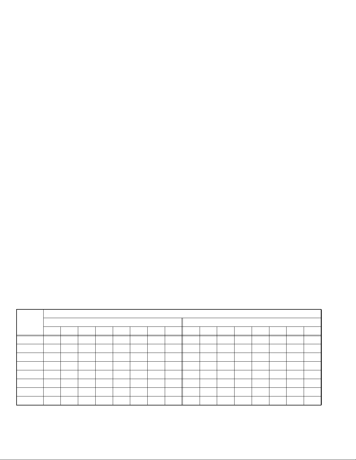
When a previous TUNER (VE-30009637) is replaced by a new TUNER (VE-30033888), it should be adjusted to the setting values in
the table below. If the TUNER of the model with the new TUNER (VE-30033888) is replaced, there is no need for adjustment.
4.1.1 SETTING VALUE OF SETTING ITEM
Make sure not to change the values that are not in the table below. If those values are changed, the unit will not operate normally.
Setting value
Item
Bit 7 Bit 6 Bit 5 Bit 4 Bit 3 Bit 2 Bit 1 Bit 0 Bit 7 Bit 6 Bit 5 Bit 4 Bit 3 Bit 2 Bit 1 Bit 0
F1H 0000100100001011
F1L 1001001001010010
F2H 0001101100011101
F2L 1000001000000010
BS1 0000001100000001
BS2 0000011000000010
BS3 1000010100001000
CB 1000111010001110
BEFORE AFTER
1-2 (No.52056B)
Page 3

4.1.2 HOW TO ENTER THE SERVICE MODE
(1) Press the [INFORMATION] key and [MUTING] key
simultaneously, and the SERVICE MENU screen will be
displayed. (Fig.1)
SERVICE MENU
JVCAK30/37 B23
OSD 080
IF1 004
IF2 069
IF3 004
IF4 031
AGC 042
VLIN 031
RGBH 007
VSOF -20
VPOF -05
> 0 3 AVL *
Fig.1
4.1.3 HOW TO SELECT THE SETTING ITEM
While the SERVICE MENU screen is displayed, press the []/[]
key and select the setting item.(Fig.2)
4.1.4 HOW TO CHANGE THE SETTING VLUE
(1) After selecting the correct 8-bit option line, by using the
dedicated number on the number key (0,1,2,3,4,5,6,7) you
can change that bit from 0 to 1 or vice versa.
Example:
Initially an option with values: "00000000"
Press "0" button: "00000001"
Press "0" button again: "00000000"
4.1.5 HOW TO STORE OF SETTING VALUE
(1) The setting value will be stored auto matically when
release the REMOTE CONTROL UNIT keys.
REMOTE CONTROL UNIT key NAME
MUTING key
Bit 7
Bit 5 Bit 3 Bit 1
00000000
Bit 6 Bit 4 Bit 2 Bit 0
JVCAK30/37 B23
NIP 018
SCP2 018
SEC2 017
F1H 00001101
F1L 00010010
F2H 00010010
F2L 00010010
BS1 00010010
BS2 00010010
BS3 00010010
> 0 3 76543210
Fig.2
INFORMATION key
MENU key
FUNCTION
[ ]/[ ] key
FUNCTION
[ ]/[ ] key
SECTION 5
TROUBLESHOOTING
Please refer to "AV-25BT6ENB and AV-25BT6ENS (No.52056)" about this section.
(No.52056B)1-3
Page 4

Victor Company of Japan, Limited
AV & MULTIMEDIA COMPANY VIDEO DISPLAY CATEGORY 12, 3-chome, Moriya-cho, kanagawa-ku, Yokohama, kanagawa-prefecture, 221-8528, Japan
(No.52056B)
Printed in Japan
VPT
 Loading...