

Page 1
A
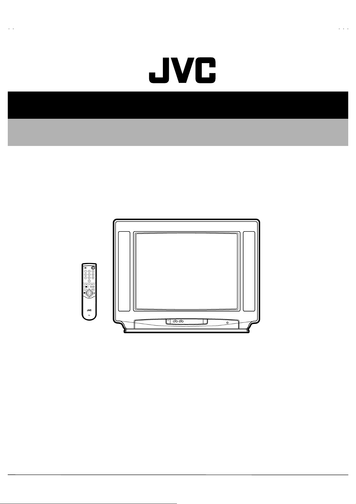
SERVICE MANUAL
COLOUR TELEVISION
AV25BT5ENS
AV25BT5ENB
AV25BT5ENS
V25BT5ENB
CONTENTS
SPECIFICATIONS
SAFETY PRECAUTIONS
FEATURES
MAIN DIFFERENCE LIST
SPECIFIC SERVICE INSTRUCTIONS
SERVICE ADJUSTMENTS
PARTS LIST
★
OPERATING INSTRUCTIONS
★
STANDARD CIRCUIT DIAGRAM
1
・・・・・・・・・・・・・・・・・・・・・・・・・・・・・・・・
・・・・・・・・・・・・・・・・・・・・・・・・・・・・・・・・・・・・・・・・・・・・・・・・・・・・・・・・・・・・・・・・
・・・・・・・・・・・・・・・・・・・・・・・・・・・・・・・・・・・・・・・・・・・・・・・・・・・・・・・・・・・・・・・・
・・・・・・・・・・・・・・・・・・・・・・・・・・・・・・・・
・・・・・・・・・・・・・・・・・・・・・・・・・・・・・・・・・・・・・・・・・・・・・・・・・・・・・・・・・・・・・
・・・・・・・・・・・・・・・・・・・・・・・・・・・・・・・・・・・・・・・・・・・・・・・・・・・・・・・・・・・・・・・・
・・・・・・・・・・・・・・・・・・・・・・・・・・・・・・・・
・・・・・・・・・・・・・・・・・・・・・・・・・・・・・・・・・・・・・・・・・・・・・・・・・・・・・・・
・・・・・・・・・・・・・・・・・・・・・・・・・・・・・・・・・・・・・・・・・・・・・・・・・・・・・・・・・・・・・・・・
・・・・・・・・・・・・・・・・・・・・・・・・・・・・・・・・・・・
・・・・・・・・・・・・・・・・・・・・・・・・・・・・・・・・・・・・・・・・・・・・・・・・・・・・・・・・・・・・・・・・
・・・・・・・・・・・・・・・・・・・・・・・・・・・・・・・・
・・・・・・・・・・・・・・・・・・・・・・・・・・・・・・・・・・・・・・・・・・・・・・・・・・・・・・・
・・・・・・・・・・・・・・・・・・・・・・・・・・・・・・・・・・・・・・・・・・・・・・・・・・・・・・・・・・・・・・・・
・・・・・・・・・・・・・・・・・・・・・・・・・・・・・・・・
・・・・・・・・・・・・・・・・・・・・・・・・・・・・・・・・・・・・・・・・・・・・・
・・・・・・・・・・・・・・・・・・・・・・・・・・・・・・・・・・・・・・・・・・・・・・・・・・・・・・・・・・・・・・・・
・・・・・・・・・・・・・・・・・・・・・・・・・・・・・・・・
・・・・・・・・・・・・・・・・・・・・・・・・・・・・・・・・・・・・・・・・・・・・・・・・・・・・・・
・・・・・・・・・・・・・・・・・・・・・・・・・・・・・・・・・・・・・・・・・・・・・・・・・・・・・・・・・・・・・・・・
・・・・・・・・・・・・・・・・・・・・・・・・・・・・・・・・
・・・・・・・・・・・・・・・・・・・・・・・・・・・・・・・・・・・・・・・・・・・・・・・・・・・・・・・・・・・・・・・・
・・・・・・・・・・・・・・・・・・・・・・・・・・・・・・・・・・・・・・・・・・・・・・・・・・・・・・・・・・・・・・・・
・・・・・・・・・・・・・・・・・・・・・・・・・・・・・・・・
・・・・・・・・・・・・・・・・・・・・・・・・・・・・・・・・・・・・・・・・・・・・・・・・
・・・・・・・・・・・・・・・・・・・・・・・・・・・・・・・・・・・・・・・・・・・・・・・・・・・・・・・・・・・・・・・・
COPYRIGHT © 2002 VICTOR COMPANY OF JAPAN, LTD.
・・・・・・・・・・・・・・・・・・・・・・・・・・・・・
・・・・・・・・・・・・・・・・・・・・・・・・・・・・・・・・・・・・・・・・・・・・・・・・・・・・・・・・・・
・・・・・・・・・・・・・・・・・・・・・・・
・・・・・・・・・・・・・・・・・・・・・・・・・・・・・・・・・・・・・・・・・・・・・・
・・・・・・・・・・・・・・・・・・・・・・・
・・・・・・・・・・・・・・・・・・・・・・・・・・・・・・・・・・・・・・・・・・・・・・
・・・・・・・・・・・・・
・・・・・・・・・・・・・・・・・・・・・・・・・・
・・・・・・・・・・・・・・・・・・・・・・
・・・・・・・・・・・・・・・・・・・・・・・・・・・・・・・・・・・・・・・・・・・・
・・・・・・・・・・・・・・・・・・・・・・・・・・・・・・・・・・・・
・・・・・・・・・・・・・・・・・・・・・・・・・・・・・・・・・・・・・・・・・・・・・・・・・・・・・・・・・・・・・・・・
・・・・・・・・・・・・・・・・
・・・・・・・・・・・・・・・・・・・・・・・・・・・・・・・・
・・・
・・・・・・
2
4
5
5
6
9
17
2-1
No.51882
Jan. 2002
Page 2
A
V25BT5ENS
A
V25BT5ENB
SPECIFICATIONS
ITEM
Dimensions (WxHxD)
Weight
TV RF System
Colour System
Teletext System
Stereo System
Tuning System
Number Of C H memory position
Receiving Frequency
Intermediate Frequency
Colour Sub Carrier Frequency
Aerial Input Terminal
Power Input
Power Consumption
Picture Tube
High Voltage
Speaker
Audio Output
Input
Output
Input Terminal
Output Terminal
Remote Control Unit
TV Mode
Video Mode
VHF (VL)
VHF (VH)
UHF
CATV
VIF Carrier
SIF Carrier
Video
S/Video
Audio (L/R)
Video
Audio (L/R)
Rear Side
Front Side
Front Side
Rear Side
69 x 54 x 47 cm
27 kg
B/G
PAL
PAL / NTSC 3.58 / NTSC 4.43
Fastext / Topt ext
A2 / German + NICAM
Frequenc y Synthesizer T uning System
100 ch
46.25MHZ ~ 168.25MHz
175.25MHz ~ 463. 25MHz
471.25MHz ~ 863. 25MHz
Super (S11-S20) & Hyper (S21-S41) bands receivable
38.9MHz
32.4MHz (6.5MHz)
32.9MHz (6.0MHz)
33.4MHz (5.5MHz)
PAL (4.43MHz), SECAM (4.43MHz), NTSC (3.58MHz/4.43MHz)
75Ohm Unbalanc ed
AC 170 ~ 270V
120W(Max.)/90W(Avg.)
25 inch measured diagonally
28kV (in cut-off service mode)
5.7 X 16 cm Oval type X 2
8W + 8W
1Vp-p, 75 Ohm
Y: 1Vp-p Positive
C: 0.286Vp-p
500 mVrms, High Impedance
1 Vp-p, 75 Ohm
500 mVrms, Low Impedance
AV1 (Video/Audio/RGB)
AV2 (Video/Audio/S-VHS)
AV3 (Video/Audio)
Headphone jack (Stereo mini jack 3.5)
AV1 (Video/Audio)
AV2 (Video/Audio) (Selected TV, AV1 or AV3)
RM-C85, Battery size:AAA/R03 x 2
Content
AV25BT5ENS (Silver)
AV25BT5ENB ( Blac k)
Design & specifications are subject to change without notice.
2
No.51882
Page 3
A
A
■■■■
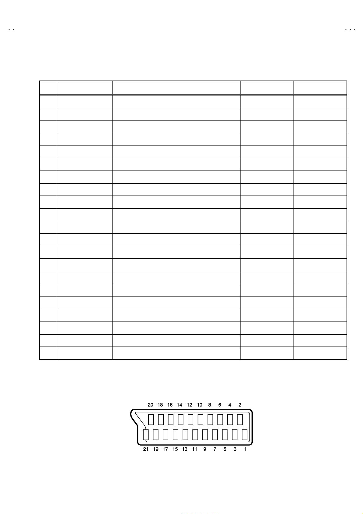
21-pin Euro connector (SCART socket) : AV1 / AV 2
(P-P= Peak to Peak, S-W= Sync tip to white peak, B-W= Blanking to white peak)
Pin
No.
Signal Designation Matching Value AV-1 AV-2
1 AUDIO R output 500mVrms(Nominal),Low impedance
2 AUDIO R input 500mVrms(Nominal),High impedance
3 AUDIO L output 500mVrms(Nominal),Low impedance
4 AUDIO GND
V25BT5ENS
V25BT5ENB
○
(TV OUT)
○○
○
(TV OUT)
○○
○
(TV/LINE OUT)
○
(TV/LINE OUT)
5 GND (B)
6 AUDIO L input 500mVrms(Nominal), High impedance
7B input
FUNCTON SW
8
(SLOW SW)
9 GND (G)
10 - NC -
11 G input
12
- NC -
13 GND (R)
14 GND (YS)
15 R / C input
16 Ys input
17 GND(VIDEO output)
18 GND(VIDEO input)
19 VIDEO output
20 VIDEO / Y input
700mV
Low : 0-3V, High : 8-12V, High impedance
700mV
R : 700mV
C : 300mV
Low : 0 – 0.4, High : 1 - 3V, 75
1V
1V
, 75
B-W
Ω○
, 75
B-W
Ω○
, 75
B-W
Ω
, 75
P-P
Ω
(Negative going sync), 75
S-W
(Negative going sync), 75
S-W
Ω○
Ω
Ω○○
○○
○○
○
○○
○○
○
○
(R/C)
○○
○○
○
(TV)
(TV/LINE OUT)
NC
NC
NC
NC
○
(only C)
NC
○
21 COMMON GND
[
Pin assignment
]
No.51882
○○
3
Page 4
A
V25BT5ENS
A
V25BT5ENB
SAFETY PRECAUTIONS
1. The design of this product contains special hardware, many
circuits and components specially for safety purposes. For
continued protection, no changes should be made to the original
design unless authorized in writing by the manufacturer.
Replacement parts must be identical t o those us ed in the original
circuits. Service should be performed by qualified personnel
only.
2. Alterations of the design or circuitry of the products should not be
made. Any design alterations or additions will void the
manufacturer's warranty and will further relieve the manufacturer
of responsibility for personal injury or property damage resulting
theref rom.
3. Many electric al and mechanical parts in the products have
special safety-related characteristics. These characteristics are
often not evident from visual inspection nor can t he protection
afforded by them necessarily be obtained by using replacement
components rated for higher voltage, wattage, etc. Replacement
parts which have these special safety characteristics are
identified in the parts list of Service manual.
components having such features are identified by shading
on the schematics and by (
manual.
have the s ame safety characteristics as the recommended
replacement part shown in the parts list of S ervice manual may
cause shock, fire, or other hazards.
The us e of a substitute replacement which does not
) on the parts list in Service
Electrical
4.
Don't short between the LIVE side ground and ISOLATED
(NEUTRAL) side ground or EARTH side ground when
repairing.
Some model's power circuit is partly different in the GND. The
differenc e of the GND is shown by the LIVE side GND, the
ISOLATED(NEUTRAL) side GND and EARTH side GND. Don't
short between the LIVE side GND and ISOLATED(NEUTRAL)
side GND or EARTH side GND and never measure with a
measuring apparatus (oscilloscope etc.) the LIVE side GND and
ISOLATED(NEUTRAL) side GND or EARTH side GND at the
same time.
If above note will not be kept, a fuse or any parts will be broken.
5. If any repair has been made to the chassis, it is recommended
that the B1 setting should be checked or adjusted (See
ADJUSTMENT OF B1 POWER SUPPLY).
6. The high voltage applied to the picture tube must conform with
that specified in Servic e manual. E xcessive high voltage can
cause an incr ease in X-Ray emission, arcing and possible
component damage, therefore operation under excessive high
voltage conditions should be kept to a minimum, or should be
prevented. If s evere arcing occurs, remove the AC power
immediately and determine the cause by visual inspection
(incorrect installation, cracked or melted high voltage harness,
poor soldering, etc.). To maintain the proper minimum level of
soft X-Ray emission, components in the high voltage circuitr y
including the picture tube must be the exact replacements or
alternatives approved by the manufacturer of the c omplete
product.
7. Do not check high voltage by drawing an arc. Use a high voltage
meter or a high voltage probe with a VT VM. Discharge the
picture tube before attempting meter connection, by connecting
a clip lead to the ground frame and connecting the other end of
the lead through a 10k: 2W resistor to the anode button.
8. W hen service is required, observe the original lead dress. Extra
precaution should be given to assure c orrect lead dress in the
high voltage circuit area. Where a short circuit has occ urred,
those components that indicate evidence of overheating should
be replaced. Always use the manufacturer's replacement
components.
9.
Isolation Check
(Safety for Electrical Shock Hazard)
After re-assembling the product, always perform an isolation
check on the exposed metal parts of the cabinet (antenna
terminals, video/audio input and output terminals, Control knobs,
metal c abinet, screwheads, earphone jack, control shafts, etc.)
to be sure the product is safe to operate without danger of
electr ic al shock.
(1)
Dielectric Strength Test
The isolation between the AC primary circuit and all metal parts
exposed to the user, particularly any exposed metal part having a
return path to the chassis should withstand a voltage of 3000V
AC (r.m.s.) for a period of one second.
(. . . . Withstand a voltage of 1100V AC (r.m.s.) to an appliance
rated up to 120V, and 3000V AC (r.m.s.) to an appliance rated
200V or more, for a period of one second.)
This method of test requires a test equipment not generally found
in the s ervice trade.
(2)
Leakage Current Check
Plug the AC line cord directly into the AC outlet (do not use a line
isolation transformer during this check.). Using a "Leakage
Current T ester", measure the leakage current from each exposed
metal part of the cabinet, particularly any exposed metal part
having a return path to the chassis, to a known good earth
ground (water pipe, etc.). Any leakage curr ent must not exceed
0.5mA AC (r.m.s.).
However, in tropical area, this must not exceed 0.2mA AC
(r.m.s.).
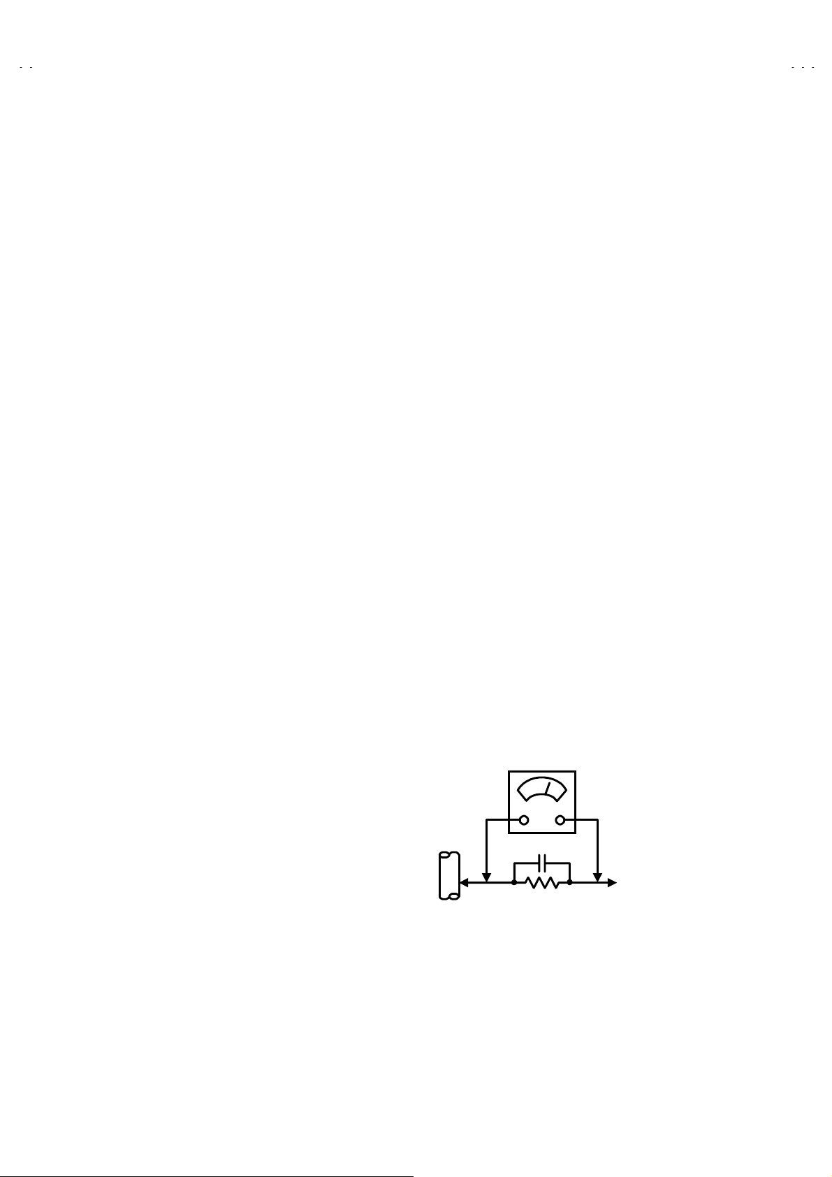
Alternate Check M ethod
zzzz
Plug the AC line cord directly into the AC outlet (do not use a line
isolation transf ormer during this check.). Use an AC voltmeter
having 1000 ohms per volt or more sensitivity in the following
manner. Connect a 1500: 10W resistor paralleled by a 0.15PF
AC-type capacitor between an exposed metal part and a known
good earth ground (water pipe, etc.). Measure the AC voltage
across the resistor with the AC voltmeter. Move the resistor
connection to each exposed metal part, particularly any exposed
metal part having a retur n path to the chassis, and measure the
AC voltage across the resistor. Now, reverse the plug in the AC
outlet and repeat each measurement. Any voltage measured
must not exceed 0.75V AC (r.m.s.). This corresponds to 0.5mA
AC (r.m.s.).
However, in tropical ar ea, this must not exceed 0.3V AC ( r.m.s.).
This corresponds to 0.2mA AC (r.m.s.).
AC VOLTMETER
0.15μF AC-T YPE
1500
GOOD EARTH GROUND
:
(HAVING 1000
OR MORE SENSITIVITY)
10W
/V,
:
PLACE THIS PROBE
ON EACH EXPOSED
METAL PART
4
No.51882
Page 5
A
A
FEATURES
V25BT5ENS
V25BT5ENB
1. It is a remte controlled color television.
2. 100 programs from VHF, UHF bands or cable channels can be
preset.
3. It can tune cable channels.
4. Controlling the TV is very easy by its menu driven s ystem.
5. It has two Euroconnector s ockets f or external device (such as
video recorder, video games, audio set, etc.)
6. Front AV Input available.
7. Stereo sound syst ems (German + Nicam) ar e available.
8. Full function Teletext (F astext, Toptext).
9. It is possible to connect headphone.
10. Direct channel access.
11. APS (Automatic Programming System).
12. All programs can be named.
13. Forward or backward automatic tuning.
14. Automatic sound mute when no transmission.
15. 5 minutes after the broadcasting (closedown), the TV switches
itself automatic ally to stand-by mode.
MAIN DIFFERENCE LIST
MODEL No.
Parts Name
MAIN PWB VE-20073443
F CARTON BOX VE-20076975 VE-20076972
AV25BT5ENS
(Silver)
AV25BT5ENB
(Black)
←
INST BOOK VE-20076973 VE-20076960
RATING LABEL VE-20076974 VE-20076961
FRONT CABINET VE-20043531 VE-20016402
BACK COVER VE-20004635 VE-20016402
No.51882
5
Page 6
A
V25BT5ENS
A
V25BT5ENB
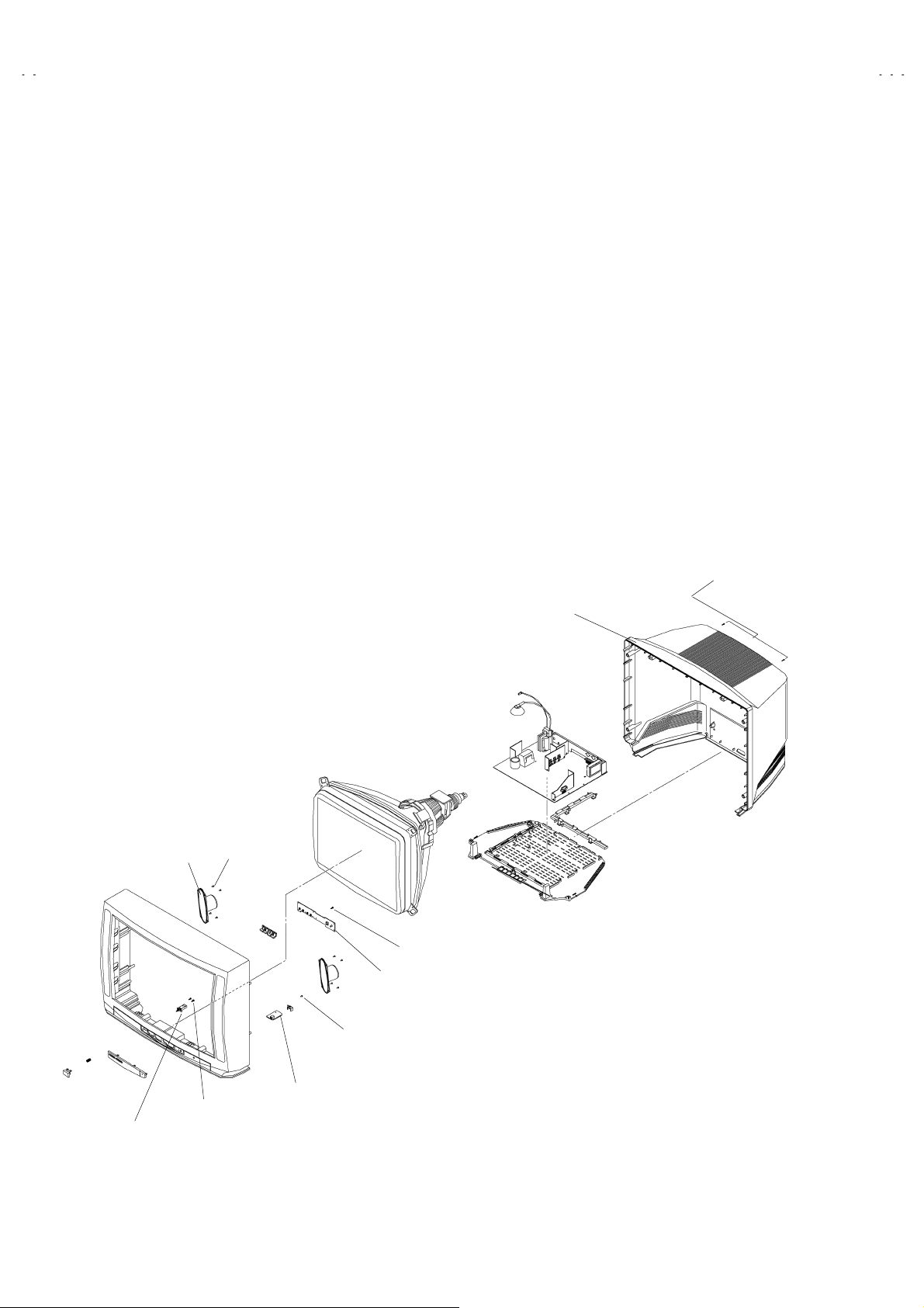
SPECIFIC SERVICE INSTRUCTIONS
DISASSEMBLY PROCEDURE
REMOVING THE REAR COVER
1. Remove the 8 screws marked A.
2. Withdraw the rear cover toward you.
REMOVING THE MAIN PWB ASS’Y
After removing the rear cover.
z
1. You can pull out the MAIN PWB ASS’Y.
REMOVING THE HEADPHONE JACK PWB ASS’Y
After removing the rear cover.
z
1. Remove the 1 screw marked B.
2. Remove the HEADPHONE JACK PWB ASS’Y & BRACKET.
REMOVING THE SPEAKER
After removing the rear cover.
z
1. Remove the 4 screws marked C.
2. Remove the SPEAKER.
REMOVING THE FRONT CONTROL PWB
After removing the rear cover.
z
1. Remove the MAIN PWB ASS’Y.
2. Remove the 4 screws marked D and remove the FRONT
CONTROL PWB.
REMOVING THE POWER SW
After removing the rear cover.
z
1. Remove the MAIN PWB ASS’Y.
2. Remove the 2 screws marked E, and remove the POWER SW.
SPEAKER
(×8)
A
REAR COVER
C
(×4)
D
FRONT CONTROL PWB
B
(×1)
HEADPHONE JACK PWB
E
(×2)
POWER SW
6
No.51882
Page 7

A
A
SETTING OF THE LAST MEMORY FOR SHIPMENT
■■■■
USER SETTING VALUES
Setting Item Setting Value Setting Item Setting Value
SOUND MENU FEATURE MENU
BASS CENTER SLEEP TIMER OFF
V25BT5ENS
V25BT5ENB
TREBLE
BALANCE
EFFECT OFF
PICTURE MENU INSTALL TV CONFIG. MENU
BRIGHTNESS LANGUAGE ENGLISH
COLOUR COUNTRY ?
CONTRAST AV-2 OUTPUT TV
SHARPNESS
HUE (only NTSC)
PICTURE MODE AUTO
■
SETTING APS BIT IN SERVICE MENU
1) Enter s ervice menu in TV mode by pressing “INFO ” and “MUTING” keys simultaneously. Service Menu will appear.
2) Select OPTIONS by pressing Up/Down keys on remote control unit.
3) Enter OPTIONS by pressing Left/Right keys on remote control unit.
4) Select OPTION 8 by pressing Up/D own keys on remote control unit.
5) Selected bit in one OPTION is shown by blinking character. Select B2 by pressing Left/Right keys on remote contr ol unit.
DO NOT CHANGE ANY OTHER BIT.
6) Press digit key “1” to s et APS bit.
7) Press “STANDARD” key on remote contr ol unit to exit s ervice mode.
These adjust are automatically
restored when APS bit in Service
menu is s et.
The proc edure f or setting APS
bit is described bellow.
↑
↑
CHILD LOCK OFF
No.51882
7
Page 8

A
V25BT5ENS
A
V25BT5ENB
REPLACEMENT OF CHIP COMPONENT
CAUTIONS
1. Avoid heating for more than 3 seconds.
2. Do not rub the electr odes and the resist parts of the pattern.
3. W hen removing a chip part, melt the solder adequately.
4. Do not reuse a chip part after removing it.
SOLDERING IRON
1. Use a high insulation soldering iron with a thin pointed end of it.
2. A 30w soldering iron is recommended for easily removing parts.
REPLACEMENT STEPS
How to remove Chip parts
1.
Resistors, capacit ors, etc.
(1) As shown in the figure, pus h the part with tweezers and
alternately melt the solder at each end.
2. How to install Chip parts
Resistors, capacit ors, etc.
(1) Apply solder to the pattern as indicated in the figure.
(2) Shift with tweezers and remove the chip part.
Transistors, diodes, variable resistors, etc.
(1) Apply extra s older to each lead.
SOLDER
(2) As shown in the figure, pus h the part with tweezers and
alternately melt the solder at each lead. Shift and remove
the chip part.
SOLDER
(2) Grasp the chip part with tweezers and place it on the
solder. Then heat and melt the solder at both ends of the
chip part.
Transistors, diodes, variable resistors, etc.
(1) Apply solder to the pattern as indicated in the figure.
(2) Grasp the chip part with tweezers and place it on the
solder.
(3) First solder lead
(4) Then solder leads
as indicated in the figur e.
A
A
B
C
and C.
B
A
B
Note : After remov ing the part, remove remaining solder from
the pattern.
8
No. 51882
C
Page 9

A
A
SERVICE ADJUSTMENTS
ADJUSTMENT PREPARATION:
1. You can make the necessary adjustments for this un it with
either the Remote Control Unit or With the adjustment tools
and parts as given below.
2. Adjustment with the Remote Control Unit is made on the
basis of the initial setting values, however, the new setting
values which set the scr een to its optimum condition may
differ from the initial settings.
3. Make sure that AC power is turned on correctly.
4. Turn on the power for set and test equipment before use, and
start the adjustment procedures after waiting at least 30 minutes.
5. Unless otherwise specified, prepare the most suitable reception
or input signal f or adjustment.
6. Never touch any adjustment parts which are not specified in the
list for this adjust ment - var iable resistors, transformers,
condensers, etc.
7. Presetting before adjustment.
Unless otherwise specified in the adjustment instructions, preset
the following functions with the r emote c ontrol unit:
VIDEO STATUS STANDARD
TINT/COLOR
PICTURE/BRIGHT
DETAIL
V25BT5ENS
V25BT5ENB
CENTER
ADJUSTMENT EQUIPMENT
1. DC voltmeter (or digital voltmeter)
2. Signal generator (Pattern generator)[PAL/SECAM/NTSC
3. Remote c ontrol unit
MAIN PARTS LOCATIONS
LED
REMOCON
RECEIVER
IC502
MEMOR Y IC
VIDEO R L
AUDIO.
IC501
MICOM
]
TOP
MENU
(+)
(+) (-)
(+)(+)
(-)
(-)(-)
PROG
/Ch.
(+)
(+) (-)
(+)(+)
VOL
(-)
(-)(-)
FRONT
FBT
MULTI SOUND PWB
SCART
jack
TUNER
AV-1 AV-2
SCART
jack
No. 51882
(Indicated [150/115V]
B1
on the bottom side)
UPPER : FOCUS VR
LOWER : SCREEN VR
9
Page 10

A
V25BT5ENS
A
A
V25BT5ENB
BASIC OPERATION SERVICE MENU
■■■■
HOW TO ENTER THE SERVICE MODE
1) Press the
REMOTE CONTROL UNIT simultaneously.
■■■■
SELECTION OF ADJUSTMENT ITEMS
1) Press the UP ( ) or
the service menu item.
2) Press the
enter ADJUSTMENT SCREEN.
3) Select the ADJUST No., us e
key of remote control unit.
4) To change the selected parameter, use
and
■
HOW TO EXIT SERVICE MODE
1) Press the
■■■■
ADJUSTMENT SERVICE MENU
ADJUSTMENT ITEM
AGC 03 AGC
IF-PLL NEGATIVE 04 IF-PLL Negative
IF-PLL POSITIVE 05 IF-PLL Positive
VERTICAL ZOOM
VERTICAL SCROLL
4 : 3 HORIZONTAL SHIFT
VERTICAL SLOPE
VERTICAL AMPLITUDE
S-CORRE CTION
VERTICAL SHIFT
EW W IDTH
EW PARABOLA WIDTH
EW CORNER PARABOLA
EW TRAPEZIUM
INFORMATION
RIGHT
( ) key.
LEFT
STANDARD
( ) or
key and
DOWN
LEFT
Key on REMOTE CONTROL UNIT.
MUTING
( ) key and select
( ) key and
RIGHT
ADJUST
No.
00 White Point RED
01 White Point GREENWHITE BALANCE
02 White Point BLUE
06 Y-Delay PAL
07 Y-Delay SECAMLUMINANCE DELAY
08 Y-Delay NTS C
10 4 : 3 PICTURE MODE
21 16 : 9 PICTURE MODE
11 4 : 3 PICTURE MODE
22 16 : 9 PICTURE MODE
12 4 : 3 PICTURE MODE
23 16 : 9 PICTURE MODE
13 4 : 3 PICTURE MODE
24 16 : 9 PICTURE MODE
14 4 : 3 PICTURE MODE
25 16 : 9 PICTURE MODE
15 4 : 3 PICTURE MODE
26 16 : 9 PICTURE MODE
16 4 : 3 PICTURE MODE
27 16 : 9 PICTURE MODE
17 4 : 3 PICTURE MODE
28 16 : 9 PICTURE MODE
18 4 : 3 PICTURE MODE
29 16 : 9 PICTURE MODE
19 4 : 3 PICTURE MODE
30 16 : 9 PICTURE MODE
20 4 : 3 PICTURE MODE
31 16 : 9 PICTURE MODE
( ) /
RIGHT
key of
( )
LEFT
( )
DISCRIPTION
SERVICE
MENU ITEM
PARAMETER
VALUE
MUTING key
UP / DOWN
(
/
INFORMATION
key
SERVICE
ADJUST…..
OPTIONS…..
SERVICE MENU SCREEN
ADJUST
***
OUT UP
REMOTE CONTROL UNIT key NAME
) key
*** ******
ADJUSTMENT SCREEN
DJUST No.
PARAMETER
STANDARD key
RIGHT / LEFT
(
) key
/
10
No. 51882
Page 11

A
A
ADJUSTMENTS
Item
SCREEN
VOLTAGE
Adju stment
Measurin g
instrument
Signal
Generator
Remote
Control
unit
SERVICE
ADJUST…..
OPTIONS…..
Test point Adjustment part Description
SERVICE MENU
SCREEN VR
[FBT]
OPTION 02
V25BT5ENS
V25BT5ENB
1. Receive a
2. Enter the option settings in the SERVICE MENU.
3. Press the UP / DOW N (
4. To change bit 6, come on to it by using L / R (
make it “1” by pressing “1” white bit 2 is blinking.
5. Observe the thin horizontal blue-white line in the middle of the
screen, and adjust the lower VR of the FBT, until the line is in
its thinnest visible thickness.
6. Then make Option 02 bit 6 “0” , by pressing “ 0” on the r emote
control unit, although you do not see any picture.
PAL
colour bar.
▲
/
) key, and Enter
▼
Option 02
) key and
/
.
FOCUS
Adju stment
SELECT OPTION menu
FBT
FOCOUS
SCREEN
Signal
generator
FOCUS VR
[FBT]
1. Receive a
2. Adjust the upper VR of the FBT, until you get the Optinum
focus, the sharpest picture.
circle pattern.
PAL
B1
VOLTAGE
check
DC
Voltmeter
Marked
[150/115V]
on the
MAIN PWB
No. 51882
1. Check whether the voltage at the point named and silk
screened as “150 / 115V” on the MAIN PW B is 150V DC.
11
Page 12

A
V25BT5ENS
A
V25BT5ENB
Item
WHITE
BALANCE
Measurin g
instruments
Signal
generator
Test point Adjustment part Description
ADJUST 00
(White point
ADJUST 01
(White
point
-
GREEN)
ADJUST 02
(White point
- BLUE)
- RED)
[LOW LIGHT]
1. Receive a whole black signal.
2. Adjust the <Adjust 00>, <Adjust 01>, <Adjust 02>, in the
SERVICE MENU s o that the entire screen do not shine black.
[HIGH LIGHT]
1. Receive a white and black signal (colour off).
2. Adjust the <Adjust 00>, <Adjust 01>, <Adjust 02>, in the
SERVICE MENU so that the whiteness in the screen become
sharp.
AGC
Adju stment
IF-PLL
NEGATIVE
Adju stment
IF-PLL
POSITIVE
Adju stment
DC
voltmeter
ADJUST 03
ADJUST 04
ADJUST 05
1. Receive a any broadcast.
2. Select
3. Connect a DC voltmeter to pin 1 of the tuner. Change the
<ADJUST 03>
AGC parameter until you see 3.70V DC on voltmeter display.
from SERVICE MENU
1. Select
2. Adjustment value is set to 80 as a default value.
<ADJUST 04>
from SERVICE MENU.
1. Select
2. Adjustment value is set to 80 as a default value.
<ADJUST 05>
from SERVICE MENU.
12
No. 51882
Page 13

A
V25BT5ENS
A
V25BT5ENB
Item
LUMINANCE
DELAY
Adju stment
Measurin g
instruments
Signal
generator
Test point Adjustment part Description
Adjust 06 [ Y-Delay PAL ]
1. Receive a
2. Select
3. Adjust Y-Delay PAL till the colour transients on the colour
bar of the pattern become as sharper and colours between
transients do not mix with each other as possible.
Note: If the SAW filter is one of the G1965M, J1951M, K2958M,
K2962M, G3957M, K6256K, K6259K or M1963M, there is
constant group delay distortion, so for an equal delay of
the luminance and chrominance signal the delay must be
set at a value of 160nS. This means the adjustment must
be set to the maximum value.
Adju st 07 [ Y-Delay SECAM ]
1. Receive a
2. Select
3. Adjust
colour bar of the pattern become as sharper and colours
between transients do not mix with each other as possible.
Note: If the SAW filter is one of the G1965M, K2958M,
K2962M, G3957M, K6256K or K6259K, there is constant
group delay distortion, so for an equal delay of the
luminance and chrominance signal the delay must be s et
at a value of 160nS. This means the adjustment must be
set to the maximum value.
colour bar signal.
PAL
<Adjust 06>
SECAM
<Adjust 07>
Y-Delay SECAM
from SERVICE MENU.
colour bar signal.
from SERVICE MENU.
till the colour transients on the
Adju st 08 [ Y-Delay NTSC ]
1. Receive a
2. Select
3. Adjust
bar of the pattern become as sharper and colours between
transients do not mix with each other as possible.
Note: If the SAW filter is M1963M, there is constant group delay
distortion, so for an equal delay of the luminanc e and
chrominance signal the delay must be set at a value of
160nS. This means the adjustment must be set to the
maximum value.
NTSC
<Adjust 08>
Y-Delay NTSC
colour bar signal.
from SERVICE MENU.
till the c olour transients on the colour
No. 51882
13
Page 14

A
V25BT5ENS
A
V25BT5ENB
Item
VERTICAL
ZOOM
Adju stment
VERTICAL
SCROLL
Adju stment
4 : 3
HORIZONTAL
SHIFT
Adju stment
Measurin g
instruments
Signal
generator
Signal
generator
Signal
generator
Test point Adjustment part Description
Adjust 10 ( 4 : 3 )
Adjust 21 ( 16 : 9 )
Adjust 11 ( 4 : 3 )
Adjust 22 ( 16 : 9 )
Adjust 12 ( 4 : 3 )
Adjust 23 ( 16 : 9 )
1. Receive a
2. Set
< 4 : 3 aspect mode >
3. Select
4. Change vertical zoom till you see the upper and lower limit
5. Set
6. Adjusts with the step which is the s ame above from 3 to 4
1. Receive a
2. Set
3. Select
4. Change vertical scroll till you s ee the circle exactly un the
5. Set
6. Adjusts with the step which is the same above from 3 to 4
1. Receive a
2. Set
3. Select
4. Change horizontal shift till the picture is horizontally
5. Set
6. Adjusts with the step which is the same above from 3 to 4
< ADJUST 10 >
of the circle as close to the upper and lower limit of the
picture tube as possible.
< 16 : 9 aspect mode >
about the 16 : 9 aspect mode, too.
< 4 : 3 aspect mode >
< ADJUST 11 >
middle of the screen.
< 16 : 9 aspect mode >
about the 16 : 9 aspect mode, too.
< 4 : 3 aspect mode >
< ADJUST 12 >
centered. Check whether this adjustment is correct after
completing Servic e Mode Adjustment.
< 16 : 9 aspect mode >
about the 16 : 9 aspect mode, too.
circle test pattern.
PAL
from SERVICE MENU.
circle test pattern.
PAL
from SERVICE MENU.
RED PURITY
.
.
.
.
test pattern.
.
from SERVICE MENU.
.
VERTICAL
SLOPE
Adju stment
VERTICAL
AM PLITU DE
Adju stment
Signal
generator
Signal
generator
Adjust 13 ( 4 : 3 )
Adjust 24 ( 16 : 9 )
Adjust 14 ( 4 : 3 )
Adjust 25 ( 16 : 9 )
1. Receive a
2. Set
3. Select
4. Change vertic al slope till the size of squares on both the
upper and lower part of test pattern become equal to the
squares laying on the vertical centre of the test pattern.
5. Check and readjust VERTICAL SLO PE item if the
adjustment becomes improper after some other geometric
adjustments are done.
6. Set
7. Adjusts with the step which is the s ame above from 3 to 5
about the 16 : 9 aspect mode, too.
1. Receive a
2. Set
3. Select
4. Change vertical slope till horizontal black lines on both the
upper and lower part of the test pattern become very close
to the upper and lower horizontal sides of picture tube and
nearly about to disappear.
5. Check and readjust VERTICAL AMPLITUDE item if the
adjustment becomes improper after some other geometric
adjustments are done.
6. Set
7. Adjusts with the step which is the s ame above from 3 to 5
about the 16 : 9 aspect mode, too.
CROSS-HATCH
< 4 : 3 aspect mode >
< ADJUST 13 >
< 16 : 9 aspect mode >
test pattern signal.
PAL
< 4 : 3 aspect mode >
< ADJUST 14 >
< 16 : 9 aspect mode >
signal.
.
from SERVICE MENU.
.
.
from SERVICE MENU.
.
14
No. 51882
Page 15

A
V25BT5ENS
A
V25BT5ENB
Item
S-CORRECTION
Adju stment
VERTICAL
SHIFT
Adju stment
EW WIDTH
Adju stment
Measurin g
instrument
Signal
generator
Signal
generator
Signal
generator
Test point Adjustment part Description
Adjust 15 ( 4 : 3 )
Adjust 26 ( 16 : 9 )
Adjust 16 ( 4 : 3 )
Adjust 27 ( 16 : 9 )
Adjust 17 ( 4 : 3 )
Adjust 28 ( 16 : 9 )
1. Receive a
2. Set
< 4 : 3 aspect mode >
3. Select
4. Change S-correction till the middle part of the circle is round
5. Set
6. Adjusts with the step which is the same above fr om 3 to 4
1. Receive a
2. Set
3. Select
4. Change Vertic al Shift till the t est pattern is vertically c entred,
5. Check and readjust Vertical Shif t item if the adjust ment
6. Set
7. Adjusts with the step which is the same above from 3 to 5
1. Receive a
2. Set
3. Select
4. Change EW Width till the vertical black and white bars on
5. Set
6. Adjusts with the step which is the same above from 3 to 4
< ADJUST 15 >
as possible.
< 16 : 9 aspect mode >
about the 16 : 9 aspect mode, too.
in the top and the bottom and on either side to find ).
< 4 : 3 aspect mode >
< ADJUST 16 >
i.e. horizontal line at the centre pattern is in equal distanc e
both to upper and lower side of the picture tube.
becomes improper after some other geometric adjustments
are done.
< 16 : 9 aspect mode >
about the 16 : 9 aspect mode, too.
< 4 : 3 aspect mode >
< ADJUST 17 >
both left and right side of the pattern exactly disappear.
< 16 : 9 aspect mode >
about the 16 : 9 aspect mode, too.
circle pattern signal.
PAL
.
from SERVICE MENU.
.
test pattern signal ( or the symmetrical signal
PAL
.
from SERVICE MENU.
.
test pattern signal.
PAL
.
from SERVICE MENU.
.
EW
PARABOLA
WIDTH
Adju stment
EW CORNER
PARABOLA
Adju stment
Signal
generator
Signal
generator
Adjust 18 ( 4 : 3 )
Adjust 29 ( 16 : 9 )
Adjust 19 ( 4 : 3 )
Adjust 30 ( 16 : 9 )
1. Receive a
2. Set
< 4 : 3 aspect mode >
3. Select
4. Change EW Parabola Width till vertical lines close to the both
5. Check and readjust EW Parabola W idth item if the
6. Set
7. Adjusts with the step which is the same above from 3 to 5
1. Receive a
2. Set
3. Select
4. Change EW Corner Parabola till vertical lines at the corners
5. Check and readjust EW Corner Parabola item if the
6. Set
7. Adjusts with the step which is the same above from 3 to 5
< ADJUST 18 >
sides of the picture frame become parallel to ver tical side of
picture tube.
adjustment becomes improper after some other geometric
adjustments are done.
< 16 : 9 aspect mode >
about the 16 : 9 aspect mode, too.
< 4 : 3 aspect mode >
< ADJUST 19 >
of both sides of picture frame become vertical and parallel to
vertical corner sides of picture tube.
adjustment becomes improper after some other geometric
adjustments are done.
< 16 : 9 aspect mode >
about the 16 : 9 aspect mode, too.
test pattern signal.
PAL
test pattern signal.
PAL
.
from SERVICE MENU.
.
.
from SERVICE MENU.
.
No. 51882
15
Page 16

A
V25BT5ENS
A
V25BT5ENB
Item
EW
TRAPEZIUM
Adju stment
Measurin g
instrument
Signal
generator
Test point Adjustment part Description
Adjust 20 ( 4 : 3 )
Adjust 31 ( 16 : 9 )
1. Receive a
2. Set
< 4 : 3 aspect mode >
3. Select
4. Change EW Trapezium till vertical lines, especially lines at
5. Check and readjust EW Trapezium item if the adjustment
6. Set
7. Adjusts with the step which is the same above from 3 to 5
< ADJUST 20 >
the sides of the picture frame became parallel to the both
sides of picture tube as possible.
becomes improper after some other geometric adjustment.
< 16 : 9 aspect mode >
about the 16 : 9 aspect mode, too.
circle pattern signal.
PAL
from SERVICE MENU.
.
.
16
No. 51882
Page 17

VICTOR COMPANY OF JAPAN, LIMITED
HOME AV NETWORK BUSINESS UNIT 12, 3-chome, Moriya-cho, Kanagawa-ku, Yokohama, Kanagawa-prefecture, 221-8528, Japan
4
VP 0201
DP205180
 Loading...