

Page 1
AV28WT5EPS AV24WT5EPS
AV28WT5EIS AV24WT5EIS
AV28WT5EKS AV24WT5EKS
SERVICE MANUAL
COLOUR TELEVISION
AV28WT5EPS AV24WT5EPS
AV28WT5EIS AV24WT5EIS
BASIC CHASSIS
ⅡⅡⅡⅡ
JK
AV28WT5EKS AV24WT5EKS
CONTENTS
!
SPECIFICATIONS
!
SAFETY PRECAUTIONS
!
WARNING
!
FEATURES
!
MAIN DIFFERENCE PARTS LIST
!
SPECIFIC SERVICE INSTRUCTIONS
!
SERVICE ADJUSTM ENTS
!
PARTS LIST
★
OPERATING INSTRUCTIONS
★
STANDARD CIRCUIT DIAGRAM
・・・・・・・・・・・・・・・・・・・・・・・・・・・・・・・・
・・・・・・・・・・・・・・・・・・・・・・・・・・・・・・・・ ・・・・・・・・・・・・・・・・・・・・・・・・・・・・・・・・
・・・・・・・・・・・・・・・・・・・・・・・・・・・・・・・・・・・・・・・・・・・・・・・・・・・・・・・・・・・・・・・・
・・・・・・・・・・・・・・・・・・・・・・・・・・・・・・・・
・・・・・・・・・・・・・・・・・・・・・・・・・・・・・・・・ ・・・・・・・・・・・・・・・・・・・・・・・・・・・・・・・・
・・・・・・・・・・・・・・・・・・・・・・・・・・・・・・・・・・・・・・・・・・・・・・・・・・・・・・・・・・・・・・・・
・・・・・・・・・・・・・・・・・・・・・・・・・・・・・・・・
・・・・・・・・・・・・・・・・・・・・・・・・・・・・・・・・ ・・・・・・・・・・・・・・・・・・・・・・・・・・・・・・・・
・・・・・・・・・・・・・・・・・・・・・・・・・・・・・・・・・・・・・・・・・・・・・・・・・・・・・・・・・・・・・・・・
・・・・・・・・・・・・・・・・・・・・・・・・・・・・・・・・
・・・・・・・・・・・・・・・・・・・・・・・・・・・・・・・・ ・・・・・・・・・・・・・・・・・・・・・・・・・・・
・・・・・・・・・・・・・・・・・・・・・・・・・・・・・・・・・・・・・・・・・・・・・・・・・・・・・・・・・・・・・・・・
・・・・・・・・・・・・・・・・・・・・・・・・・・・・・・・・
・・・・・・・・・・・・・・・・・・・・・・・・・・・・・・・・ ・・・・・・・・・・・・・・・・・・・・・・・・
・・・・・・・・・・・・・・・・・・・・・・・・・・・・・・・・・・・・・・・・・・・・・・・・・・・・・・・・・・・・・・・・
・・・・・・・・・・・・・・・・・・・・・・・・・・・・・・・・
・・・・・・・・・・・・・・・・・・・・・・・・・・・・・・・・ ・・・・・・・・・・・・・・・・・・・・・・・・・・・・・・・・
・・・・・・・・・・・・・・・・・・・・・・・・・・・・・・・・・・・・・・・・・・・・・・・・・・・・・・・・・・・・・・・・
・・・・・・・・・・・・・・・・・・・・・・・・・・・・・・・・ ・・・・
・・・・・・・・・・・・・・・・・・・・・・・・・・・・・・・・・・・・・・・・・・・・・・・・・・・・・・・・・・・・・・・・
・・・・・・・・・・・・・・・・・・・・・・・・・・・
・・・・・・・・・・・・・・・・・・・・・・・・・・・・・・・・・・・・・・・・・・・・・・・・・・・・・・
・・・・・・・・・・・・・・・・・・・・・・・・・・・・・・・・ ・・・・・・・・
・・・・・・・・・・・・・・・・・・・・・・・・・・・・・・・・・・・・・・・・・・・・・・・・・・・・・・・・・・・・・・・・
・・・・・・・・・・・・・・・・・・・・・・・・・・・・・・・・ ・・・・・・・
・・・・・・・・・・・・・・・・・・・・・・・・・・・・・・・・・・・・・・・・・・・・・・・・・・・・・・・・・・・・・・・・
・・・・・・・・・・・・・・・・・・・・・・・・・・・・・・・・
・・・・・・・・・・・・・・・・・・・・・・・・・・・・・・・・ ・・・・・・・・・・・・・・・・・・・・
・・・・・・・・・・・・・・・・・・・・・・・・・・・・・・・・・・・・・・・・・・・・・・・・・・・・・・・・・・・・・・・・
・・・・・・・・・・・・・・・・・・・・・・・・・・・・・・・・
・・・・・・・・・・・・・・・・・・・・・・・・・・・・・・・・ ・・・・・・・・・・・・・・・
・・・・・・・・・・・・・・・・・・・・・・・・・・・・・・・・・・・・・・・・・・・・・・・・・・・・・・・・・・・・・・・・
・・・・・・・・・・・・・・・・・・・・・・・・
・・・・・・・・・・・・・・・・・・・・・・・・・・・・・・・・・・・・・・・・・・・・・・・・
・・・・・・・・・・・・・・・・・・・・・・・・・・・・・・・・ ・・・・
・・・・・・・・・・・・・・・・・・・・・・・・・・・・・・・・・・・・・・・・・・・・・・・・・・・・・・・・・・・・・・・・
・・・・・・・・・・・・・・・・・・・・・・・・・・・・・・・・
・・・・・・・・・・・・・・・・・・・・・・・・・・・・・・・・ ・・・・・・・・・・・・・・・・・・・・・
・・・・・・・・・・・・・・・・・・・・・・・・・・・・・・・・・・・・・・・・・・・・・・・・・・・・・・・・・・・・・・・・
・・・・・・・・・・・・・・・・・・・・・・・・・・・・・・・・
・・・・・・・・・・・・・・・・・・・・・・・・・・・・・・・・ ・・・・・・・・・・・・・・・・・・
・・・・・・・・・・・・・・・・・・・・・・・・・・・・・・・・・・・・・・・・・・・・・・・・・・・・・・・・・・・・・・・・
・・・・・・・・・・・・・・・・・・・・
・・・・・・・・・・・・・・・・・・・・・・・・・・・・・・・・・・・・・・・・
・・・・・・・・・・・・・・・
・・・・・・・・・・・・・・・・・・・・・・・・・・・・・・
・・・・・・・・・・・・・・・・・・・・・
・・・・・・・・・・・・・・・・・・・・・・・・・・・・・・・・・・・・・・・・・・
・・・・・・・・・・・・・・・・・・
・・・・・・・・・・・・・・・・・・・・・・・・・・・・・・・・・・・・
・・・・・・・・
・・・・・・・・・・・・・・・・
・・・・・・・
・・・・・・・・・・・・・・
・・・・
・・・・・・・・
2
4
5
7
9
10
17
39
1-1
2-1
1
COPYRIGHT © 2001 VICTOR COMPANY OF JAPAN, LTD.
No.51776
Jan. 2001
Page 2
A
V28WT5EPS
A
A
V28WT5EIS
V28WT5EKS
SPECIFICATIONS
Item
Dimensions ( W
Mass
TV RF System
Colour System
Stereo System
Teletext System
Receiving Frequency
Intermediate Frequency
××××H××××
D )
VHF
UHF
French CATV
VIF Carrier
SIF Carrier
716mm×489mm×496mm
34.2kg
CCIR (B/G, I ,L) CCIR (I ) CCIR ( I )
PAL / SECAM /
NTSC (Only in EXT mode)
A2 / NICAM NICAM NICAM
FLOF (Fastext)
TOP (German system)
WST(Standard system)
47MHz ~ 470MHz 47MHz ~ 470MHz
470MHz ~ 862MHz 470MHz ~ 862MHz 470MHz ~ 862MHz
116MHz ~ 172MHz /
220MHz ~ 469MHz
38.9MHz (B/G, I ,L)/ 33.95MHz (L’) 38.9MHz ( I ) 38.9MHz ( I )
33.4MHz (5.5MHz:B/G) / 32.9MHz
(6.0MHz:I) / 32.4MHz (6.5MHz:L) /
27.45MHz (6.5MHz:L’)
AV28WT5EPS AV28WT5EIS AV28WT5EKS
(28” Model)
Content
PAL / NTSC (Only in EXT mode) PAL / NTSC (Only in EXT mode)
FLOF (Fastext)
WST(Standard system)
32.9MHz (6.0MHz:I) 32.9MHz (6.0MHz:I)
Colour Sub Carrier Freq.
PAL
SECAM
NTSC
Power Input
Power Consumption
Aerial Input Term
Picture Tube
High Voltage
Speaker
Audio Output
EXT-1/EXT-2/EXT-3
(Input / Output)
EXT-4 (Input) Video
Audio(L/R)
S / Video
AUDIO OUT (Variable)
Headphone jack
4.43MHz 4.43MHz 4.43MHz
4.40625MHz / 4.25MHz
3.58MHz / 4.43MHz 3.58MHz / 4.43MHz 3.58MHz / 4.43MHz
AC 220V~240V , 50Hz
156W(Max) / 122W(Avg),
122W/h(ITALY)
75Ωunbalanced, Coaxial
Visible size : 66cm, Measured
diagonally
1kV
30.0kV (at zero beam
current)
10cm×3cm Oval type×2
5W + 5W
21-pin Euro connector
(SCART socket)
1Vp-p 75Ω(RCA pin jack)
500mVrms(!-4dBs!), High
Impedance (!RCA pin jack!)
Y : 1V
sync Provided, when terminated
with 75Ω)
C : 0.286V
terminated with 75Ω)
0~1Vrms, Low Impedance
(RCA pin jack×2)
Stereo mini jack (φ3.5mm )
+
-1.5kV
p-p
POSITIVE (Negative
p-p
(Burst signal, when
Remote Control Unit
RM-C54 (AAA/R03 dry battery×2) RM-C55 (AA A /R03 dry battery×2)
Design & specifications are subject to change without notice
2
.
No.51776
Page 3
A
V24WT5EPS
A
A
V24WT5EIS
V24WT5EKS
SPECIFICATIONS
Item
Dimensions ( W
Mass
TV RF System
Colour System
Stereo System
Teletext System
Receiving Frequency
Intermediate Frequency
Colour Sub Carrier Freq.
Power Input
Power Consumption
Aerial Input Term
Picture Tube
High Voltage
Speaker
Audio Output
EXT-1/EXT-2/EXT-3
(Input / Output)
EXT-4 (Input) Video
AUDIO OUT
Headphone jack
××××H××××
D )
VHF
UHF
French CATV
VIF Carrier
SIF Carrier
PAL
SECAM
NTSC
Audio(L/R)
S / Video
645mm×427mm×443mm
23.1kg
CCIR (B/G, I ,L) CCIR ( I )
PAL / SECAM /
NTSC (Only in EXT mode)
A2 / NICAM NICAM
FLOF (Fastext)
TOP (German system)
WST(Standard system)
47MHz ~ 470MHz 47MHz ~ 470MHz
470MHz ~ 862MHz 470MHz ~ 862MHz 470MHz ~ 862MHz
116MHz ~ 172MHz /
220MHz ~ 469MHz
38.9MHz (B/G, I ,L) /
33.95MHz (L’)
33.4MHz (5.5MHz:B/G) / 32.9MHz
(6.0MHz:I) /32.4MHz (6.5MHz:L) /
27.45MHz (6.5MHz:L’)
4.43MHz 4.43MHz
4.40625MHz / 4.25MHz
3.58MHz / 4.43MHz 3. 58MHz / 4.43MHz
AC 220V~240V , 50Hz
127W(Max) / 92W(Avg)
92W/h(ITALY)
75Ωunbalanced, Coaxial
Visible size : 56cm, Measured
diagonally
30.0kV (at zero beam
current)
10cm×3cm Oval type×2
5W + 5W
21-pin Euro connector
(SCART socket)
1Vp-p 75Ω(RCA pin jack)
500mVrms(!-4dBs!), High
Impedance (!RCA pin jack!)
Y : 1V
sync Provided, when terminated
with 75Ω)
C : 0.286V
terminated with 75Ω)
0~1Vrms, Low Impedance
(RCA pin jack)
Stereo mini jack (φ3.5mm )
AV24WT5EPS AV24WT5EIS AV24WT5EKS
1kV
+
-1.5kV
p-p
POSITIVE (Negative
p-p
(Burst signal, when
(24” Model)
Content
PAL /
NTSC (Only in EXT mode)
FLOF (Fastext)
WST(Standard system)
38.9MHz ( I )
32.9MHz (6.0MHz:I)
Remote Control Unit
RM-C54 (AAA/R03 dry battery×2) RM-C55 (AAA/R03 dry battery×2)
Design & specifications are subject to change without notice
No.51776
3
Page 4

A
V28WT5EPS AV24WT5EPS
SAFETY PRECAUTIONS
1. The design of this product contains special hardware, many
circuits and components specially for safety purposes. For
continued protection, no changes should be made to the original
design unless authorized in writing by the manufacturer.
Replacement parts must be identical to those used in the original
circuits. Service should be performed by qualified personnel
only.
2. Alterations of the design or circuitry of the products should not be
made. Any design alterations or additions will void the
manufacturer's warranty and will further relieve the manufacturer
of responsibility for personal injury or property damage resulting
therefrom.
3. Many electrical and mechanical parts in the products have
special safety-related characteristics. These characteristics are
often not evident from visual inspection nor can the protection
afforded by them necessarily be obtained by using replacement
components rated for higher voltage, wattage, etc. Replacement
parts which have these special safety characteristics are
identified in the parts list of Service manual.
components having such features are identified by shading
on the schematics and by (
manual.
have the same safety characteristics as the recommended
replacement part shown in the parts list of Service manual may
cause shock, fire, or other hazards.
The use of a substitute replacement which does not
!!!!
) on the parts list in Service
Electrical
4.
Don't short between the LIVE side ground and ISOLATED
(NEUTRAL) side ground or EARTH side ground when
repairing.
Some model's power circuit is partly different in the GND. The
difference of the GND is shown by the LIVE : (") side GND, the
ISOLATED(NEUTRAL) : (#) side GND and EARTH : ($) side
GND. Don't short between the LIVE side GND and
ISOLATED(NEUTRAL) side GND or EARTH side GND and
never measure with a measuring apparatus (oscilloscope etc.)
the LIVE side GND and ISOLATED(NEUTRAL) side GND or
EARTH side GND at the same time.
If above note will not be kept, a fuse or any parts will be broken.
5. If any repair has been made to the chassis, it is recommended
that the B1 setting should be checked or adjusted (See
ADJUSTMENT OF B1 POWER SUPPLY).
6. The high voltage applied to the picture tube must conform with
that specified in Service manual. Excessive high voltage can
cause an increase in X-Ray emission, arcing and possible
component damage, therefore operation under excessive high
voltage conditions should be kept to a minimum, or should be
prevented. If severe arcing occurs, remove the AC power
immediately and determine the cause by visual inspection
(incorrect installation, cracked or melted high voltage harness,
poor soldering, etc.). To maintain the proper minimum level of
soft X-Ray emission, components in the high voltage circuitry
including the picture tube must be the exact replacements or
alternatives approved by the manufacturer of the complete
product.
7. Do not check high voltage by drawing an arc. Use a high voltage
meter or a high voltage probe with a VTVM. Discharge the
picture tube before attempting meter connection, by connecting
a clip lead to the ground frame and connecting t he other end of
the lead through a 10k" 2W resistor to the anode button.
8. When service is required, observe t he original lead dress. Extra
precaution should be given to assure correct lead dress in the
high voltage circuit area. Where a short circuit has occurred,
those components that indicate evidence of overheating should
be replaced. Always use the manufacturer's replacement
components.
9.
(1)
(2)
AV28WT5EPS / AV24WT5EPS
Isolation Check
(Safety for Electrical Shock Hazard)
After re-assembling the product, always perform an isolation
check on the exposed metal parts of the cabinet (antenna
terminals, video/audio input and output terminals, Control knobs,
metal cabinet, screwheads, earphone jack , control shafts, etc.)
to be sure the product is safe to operate without danger of
electrical shock.
Dielectric Strength Test
The isolation between the AC primary circuit and all metal parts
exposed to the user, particularly any exposed metal part having a
return path to the chassis should withstand a voltage of 3000V
AC (r.m.s.) for a period of one second.
(. . . . Withstand a voltage of 1100V AC (r.m.s.) to an appliance
rated up to 120V, and 3000V AC (r.m.s.) to an applianc e rated
200V or more, for a period of one second.)
This method of test requires a test equipment not generally found
in the service trade.
Leakage Current Check
Plug the AC line cord directly into the AC outlet (do not use a line
isolation transformer during this check.). Using a "Leakage
Current Tester", measure the leakage current from each exposed
metal part of the cabinet, particularly any exposed metal part
having a return path to the chassis, to a known good earth
ground (water pipe, etc.). Any leakage current m ust not exceed
0.5mA AC (r.m.s.).
However, in tropical area, this must not exceed 0.2mA AC
(r.m.s.).
""""
Alternate Check Method
Plug the AC line cord directly into the AC outlet (do not use a line
isolation transformer during this check.). Use an AC voltmeter
having 1000 ohms per volt or more sensitivity in the following
manner. Connect a 1500" 10W resistor paralleled by a 0.15#F
AC-type capacitor between an exposed metal part and a known
good earth ground (water pipe, etc.). Measure the AC voltage
across the resistor with the AC voltmeter. Move the resistor
connection to each exposed metal part, particularly any exposed
metal part having a return path to the chassis, and measure the
AC voltage across the resistor. Now, reverse the plug in the AC
outlet and repeat each measurement. Any voltage measured
must not exceed 0.75V AC (r.m.s.). This corresponds to 0.5mA
AC (r.m.s.).
However, in tropical area, this mus t not exceed 0.3V A C (r.m. s.).
This corresponds to 0.2mA AC (r.m.s.).
AC VOLTMETER
0.15μF AC-TYPE
1500
GOOD EARTH GROUND
"
(HAVING 1000
OR MORE SENSITIVITY)
10W
/V,
"
PLACE THIS PROBE
ON EACH EXPOSED
METAL PART
4
No.51776
Page 5

A
V28WT5EIS AV24WT5EIS
A
V28WT5EKS AV24WT5EKS
SAFETY PRECAUTIONS
1. The design of this product cont ains special hardware and many
circuits and components specially for safety purposes. For
continued protection, no changes should be made to the original
design unless authorized in writing by the manufacturer.
Replacement parts must be identical to those used in the original
circuits. Service should be performed by qualified personnel
only.
2. Alt erations of the design or circuit ry of the product should not be
made. Any design alterations or additions will void the
manufacturer's warranty and will further relieve the manufacturer
of responsibility for personal injury or property damage resulting
therefrom.
3. Many electrical and mechanical parts in the product have special
safety-related characteristics. These characteristics are often not
evident from visual inspection nor can the protection afforded by
them necessary be obtained by using replacement components
rated for higher voltage, wattage, etc. Replacement parts which
4. The leads in the products are routed and dressed with ties,
AV28WT5EIS / AV24WT5EIS
AV28WT5EKS / AV24WT5EKS
have these special safety characteristics are identified in the
Parts List of Service Manual. Elect rical components having such
features are identified by shading on the schemati cs and by (!)
on the Parts List in the Service Manual. The use of a substitute
replacement which does not have the same safety
characteristics as the recommended replacement part shown in
the Parts List of Service Manual m ay cause shock, fire, or ot her
hazards.
clamps, tubing’s, barriers and the like to be separated from live
parts, high temperature parts, moving parts and / or sharp edges
for the prevention of electric shock and fire hazard. When
service is required, the original lead routing and dress should be
observed, and it should be confirmed that they have been
returned to normal, after re-assembling.
WARNING
1. The equipm ent has been designed and manuf act u red t o meet internati onal saf ety standards.
2. I t is the legal responsibility of the repairer to ensure that these safety standards are maintained.
3. Repairs must be made in accordance with the relevant safety standards.
4. I t is essential that safety critical components are replaced by approved parts.
5. I f mains voltage selector is provided, check setting for local voltage.
No.51776
5
Page 6
A
V28WT5EPS AV24WT5EPS
A
A
V28WT5EIS AV24WT5EIS
V28WT5EKS AV24WT5EKS
■■■■
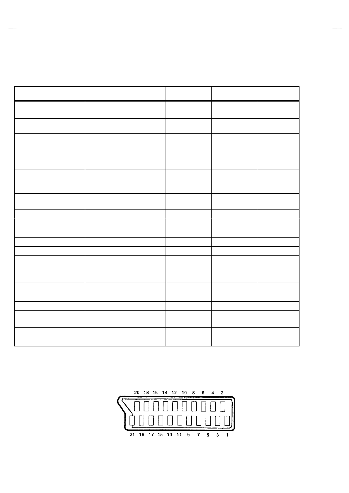
21-pin Euro connector (SCART socket) : EXT-1 / EXT-2 / EXT-3
(P-P= Peak to Peak, S-W= Sync tip to white peak, B-W= Blanking to white peak)
Pin
No.
Signal Designation Matching Value EXT-1 EXT-2 EXT-3
1 AUDIO R output 500mVrms(Nominal),
Low impedance
2 AUDIO R input 500mVrms(Nominal),
High impedance
3 AUDIO L output 500mVrms(Nominal),
Low impedance
4 AUDI O GND
5 GND (B )
6 AUDIO L input 500mVrms(Nominal),
High impedance
7 B i nput
8 FUNCT O N SW
(SLOW SW)
9 GND (G)
10 SCL3 NC
11 G input
12 SDA3 NC
13 GND (R)
14 GND (YS)
15 R / C input
16 Ys input
17 GND(VIDEO output)
18 GND(VIDEO input)
19 VIDEO output
20 VIDEO / Y input
21 COMMON GND
700mV
Low : 0-3V, High : 8-12V, High
impedance
700mV
R : 700mV
C : 300mV
Low : 0 - 0.4, High : 1 - 3V, 75
1V
P-P
1V
P-P
Ω○
, 75
B-W
Ω○
, 75
B-W
Ω
, 75
B-W
Ω
, 75
P-P
Ω○
(Negative going sync), 75
(Negative going sync), 75
Ω○
Ω○ ○ ○
○
(TV OUT)
○○○
○
(TV OUT)
○○○
○○○
○○○
○○○
○○○
○○○
○
○
(only R)
○○○
○○○
(TV)
○○○
○
(LINE OUT)
○
(LINE OUT)
NC NC
○
NC NC
○
NC NC
○
(only C)
NC NC
○
(LINE OUT)
NC
NC
NC
NC
○
(only C)
NC
[
Pin assignment
6
]
No.51776
Page 7
A
A
A
FEATURES
V28WT5EPS AV24WT5EPS
V28WT5EIS AV24WT5EIS
V28WT5EKS AV24WT5EKS
"
By preference, users can select the picture size from REGULAR,
PANORAMIC, FULL, 14:9 ZOOM, 16:9 ZOOM, 16:9 ZOOM SUB
TITLE modes. When the TV unit received WSS picture signal, the
picture can be changed to 16:9 ZOOM mode automatically.
"
The TELETEXT SYSTEM has a built-in FASTEXT, TOP(Only
AV28WT5EPS / AV24WT5EPS) and WST system.
"
Because this TV unit corresponds to multiplex broadcast, users
can enjoy music programs and sporting events with live realism.
In addition, BILINGUAL programs can be heard in their original
language.
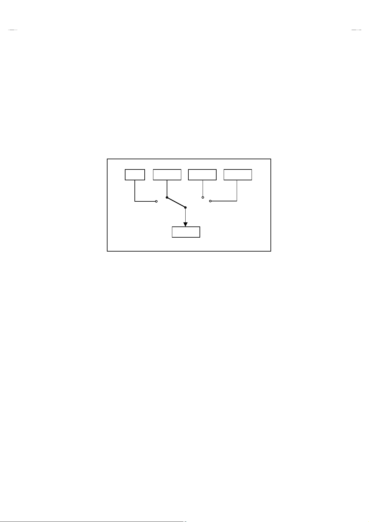
TV EXT-1 EXT-3
EXT-2
"
Built-in ECO (ECONOMY, ECOLOGY) MODE.
In accordance with the brightness in a room, the brightness
and/or contrast of the picture can be adjusted automatically to
make the optimum picture which is easy on the eye.
"
Users can make VCR dubbing of picture and sound by controlling
the AV selector to select an opt ional source at the EXT-2 output
shown in figure.
EXT-4
No.51776
7
Page 8
A
V28WT5EPS AV24WT5EPS
A
A
V28WT5EIS AV24WT5EIS
V28WT5EKS AV24WT5EKS
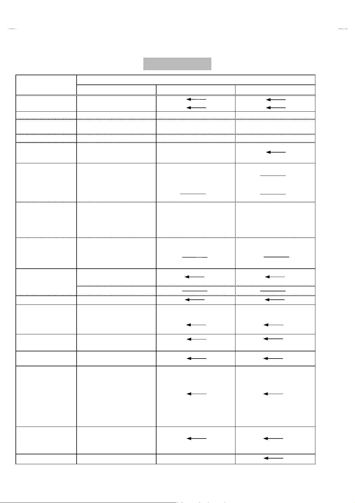
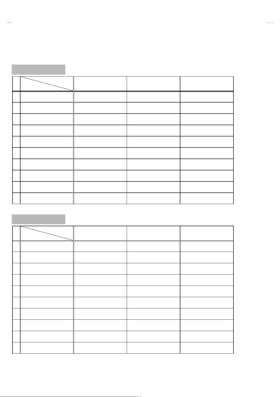
MAIN DIFFERENCE PARTS LIST
(28” Model)
Model Name
!!!!
Part Name
MAIN PWB SJK-1712A-U2
AV SEL. PWB SJK0S712A-U2
!
POWER CORD QMPK160-185-JC QMPN130-185-JC
!
RATING LABEL
EURO LABEL AEM1052-031-E AEM1052-030-E AEM1052-029-E
!
INST BOOK
REMOTE CONTROL
UNIT
X-RAY CARD AEM1061-001-E
S. DIAGRAM
ONLY ITALY(SERVICE)
REG. SHEET
AV28WT5EPS AV28WT5EIS AV28WT5EKS
SJK-1912A-U2
SJK0S912A-U2
AEM3148-001-E
LC20433-008A-U
LC20434-008A-U
LCT0897-001A-U
LCT0898-001A-U
RM-C54-1C RM-C55-1C
2824WT5-HSAEI
××
LC20080-015A-U LC20091-023A-U
LCT0900-001A-U LCT0899-001A-U
←
←
××
××
←
←
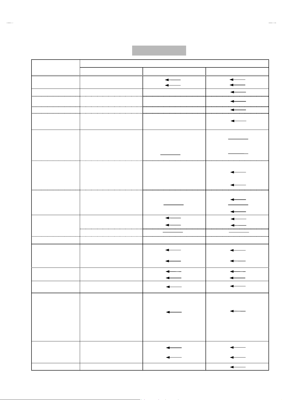
(24” Model)
Model Name
!!!!
Part Name
MAIN PWB SJK-1713A-U2
AV SEL. PWB SJK0S713A-U2
!
POWER CORD QMPK160-185-JC QMPN130-185-JC
!
RATING LABEL
EURO LABEL AEM1052-027-E AEM1052-025-E AEM1052-026-E
!
INST BOOK
REMOTE CONTROL
UNIT
X-RAY CARD AEM1060-001-E
S. DIAGRAM
ONLY ITALY(SERVICE)
REG. SHEET
AV24WT5EPS AV24WT5EIS AV24WT5EKS
SJK-1913A-U2
SJK0S913A-U2
AEM3148-001-E
LC20433-007A-U
LC20434-007A-U
LCT0897-001A-U
LCT0898-001A-U
RM-C54-1C RM-C55-1C
2824WT5-HSAEI
××
LC20080-014A-U LC20091-022A-U
LCT0900-001A-U LCT0899-001A-U
←
←
××
××
←
←
8
No.51776
Page 9
A
V28WT5EPS AV24WT5EPS
A
A
V28WT5EIS AV24WT5EIS
V28WT5EKS AV24WT5EKS
SPECIFIC SERVICE INSTRUCTIONS
REPLACEMENT OF CHIP COMPONENT
!
CAUTIONS
1. A void heating for more than 3 seconds.
2. Do not rub the elect rodes and the resist parts of the pattern.
3. When removing a chip part, melt the solder adequately.
4. Do not reuse a chip part after removing it.
!
SOLDERING IRON
1. Us e a hi gh insulat i on solderi ng iron with a thin pointed end of it.
2. A 30w solderi ng i ron is recommended for easily removi ng parts .
!
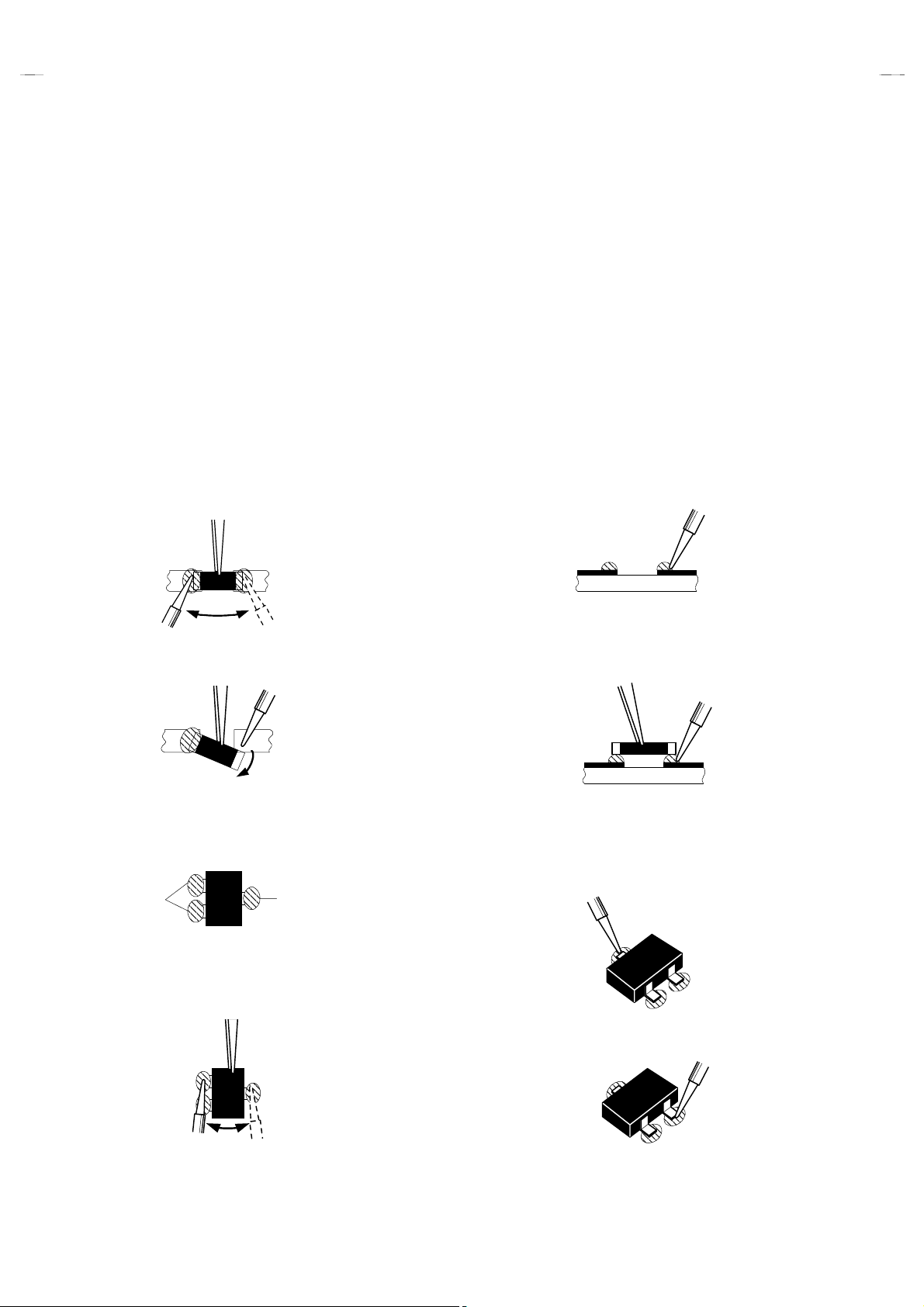
REPLACEMENT STEPS
How to remove Chip parts
1.
####
Resistors, capacitors, etc
(1) As shown in the figure, push the part with tweezers and
alternately melt the solder at each end.
(2) Shi ft with tweezers and remove the chip part.
####
Transistors, diodes, variable resistors, etc
(1) Appl y extra sol der to each lead.
SOLDER
SOLDER
2. How to install Chip parts
####
Resistors, capacitors, etc
(1) Appl y solder to the pattern as indicated in the figure.
(2) Gras p the chip part with tweezers and place it on the solder.
Then heat and melt the solder at both ends of the chip part.
####
Transistors, diodes, variable resistors, etc
(1) Appl y solder to the pattern as indicated in the figure.
(2) Grasp the chip part with tweezers and place it on the solder.
(3) First solder lead
as indicated in the figure.
A
A
and C.
B
B
B
9
(2) As shown in the figure, push the part with tweezers and
alternately melt the solder at each lead. Shift and remove the
chip part.
(4) Then solder leads
Note : After removing the part, remove remaining solder from the
pattern.
No.51776
C
A
C
Page 10
A
V28WT5EPS
A
A
A
A
V28WT5EIS
V28WT5EKS
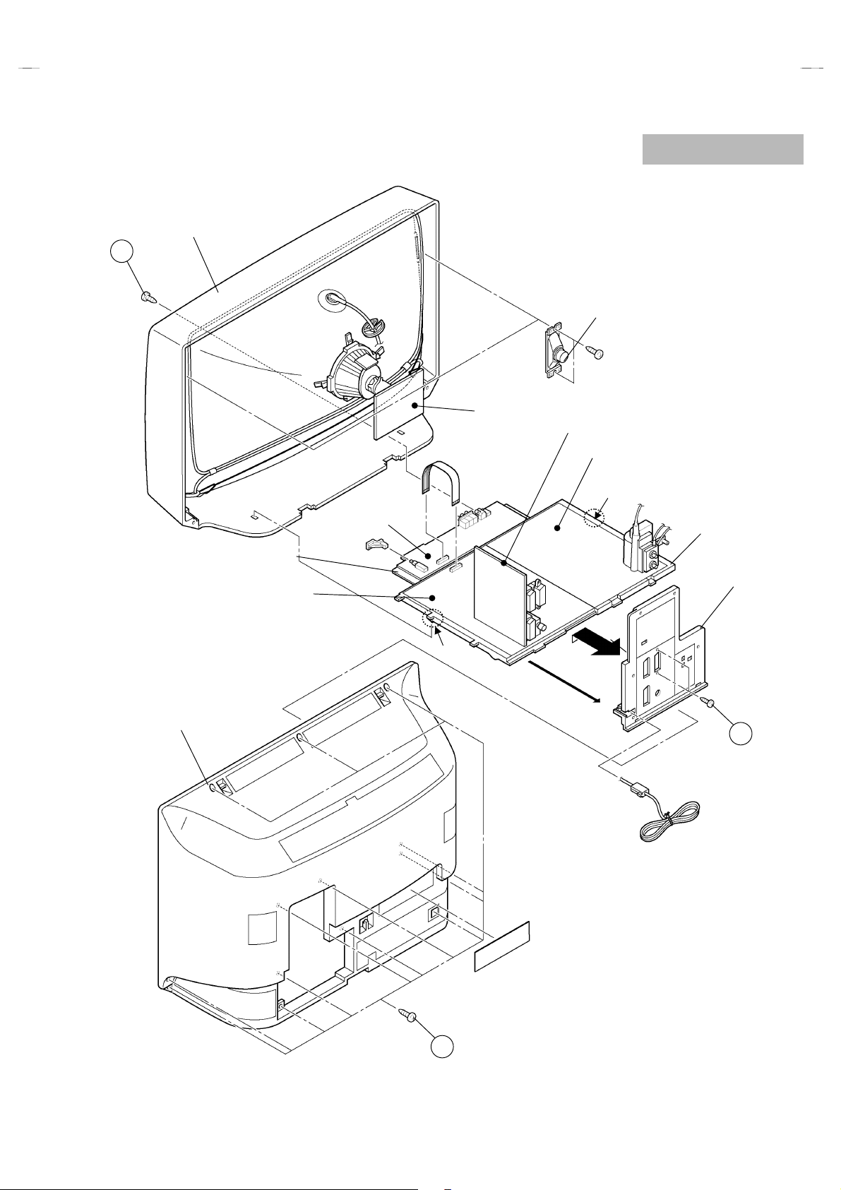
DISASSEMBLY PROCEDURE
(28” Model)
REMOVING THE REAR COVER
1. Unplug the power cord.
”
2. Remove the 13 screws marked
3. Withdraw the rear cover toward you.
“
as shown in the Fig. 1.
AAAA
REMOVING THE CHASSIS
"
After removing the rear cover.
”
1. Remove t he s crew mark ed
FRONT CABINET as shown in the Fig. 1.
2. Slightly raise the both sides of t he chassis by hand and remove
the two claws under the both sides of the chassis from the front
cabinet.
3. Withdraw the chassis backward.
(If necessary, take off the wire clamp, connectors etc.)
“
on the S/VIDEO terminal of
BBBB
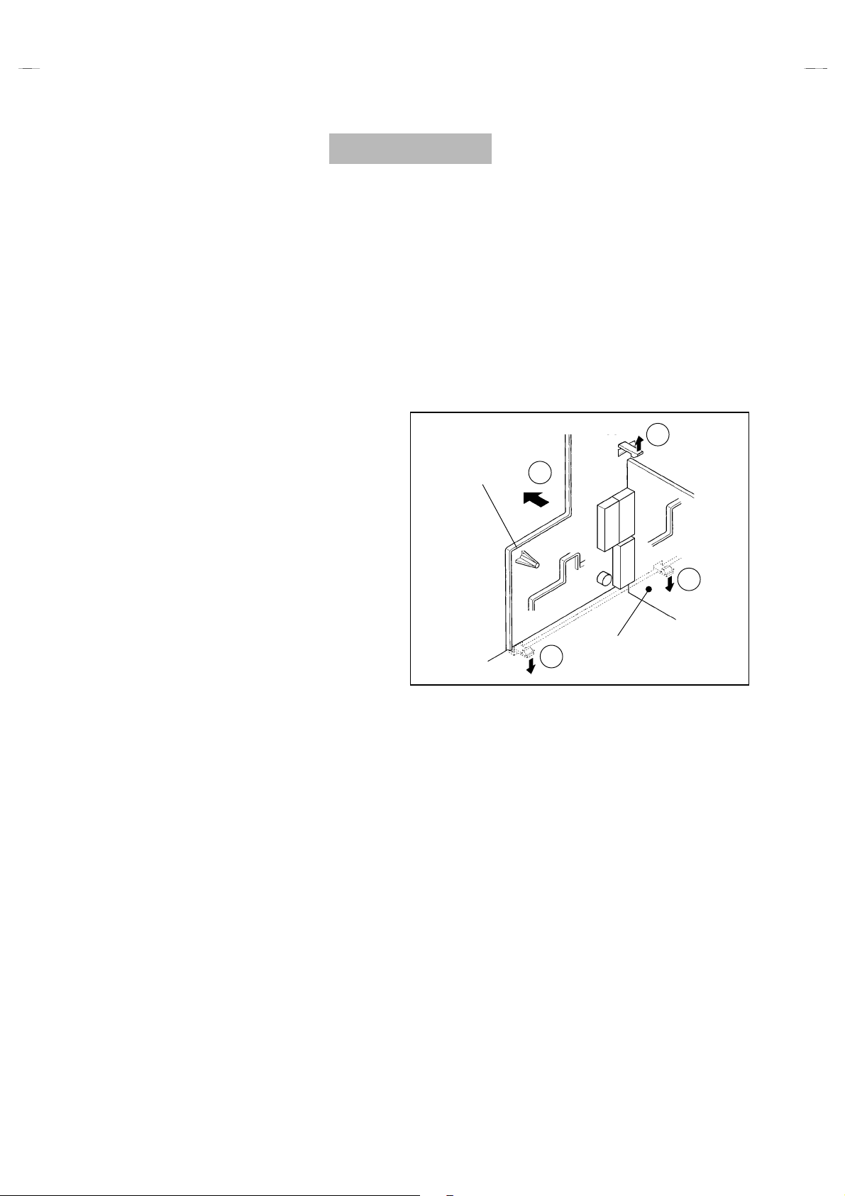
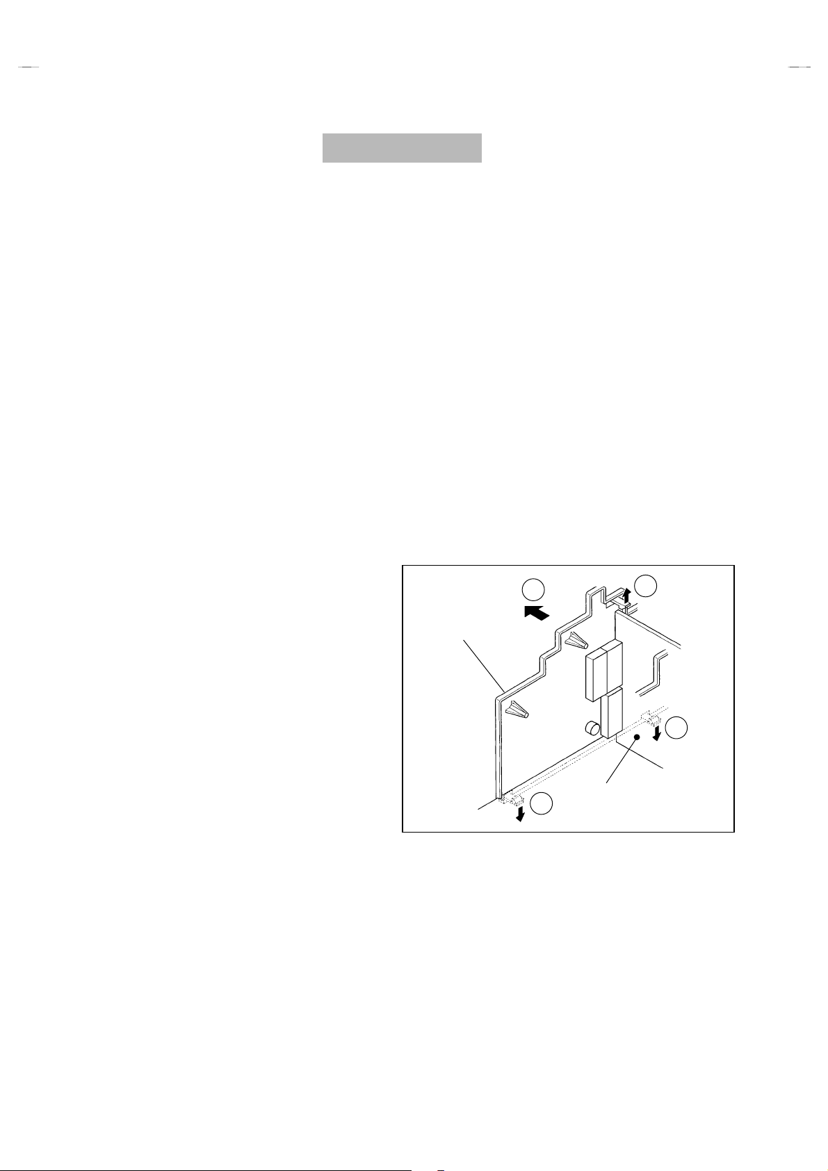
REMOVING THE AV TERMINAL BOARD
"
After removing the rear cover.
”
1. Remove the 2 screws marked
2. Remove the claws marked
shown in Fig. 2.
3. While raising the claw marked
TERMINAL BOARD slightly in the directi on of arrow
shown in Fig. 2.
“
“
as shown in the Fig. 1.
CCCC
”
under the CHASSIS as
DDDD
”
“
, remove the top of the AV
EEEE
“
FFFF
”
as
V TERMINAL
BOARD
E
F
D
REMOVING THE SPEAKER
"
After removing the rear cover.
”
1. Remove the 2 screws marked
2. Follow the same steps when removing the other hand speaker.
“
as shown in Fig. 1.
GGGG
CHECKING THE PW BOARD
To check the back side of the PW Board.
1) Pull out the chassis. (Refer to REMOVING THE CHASSIS).
2) Erect the chassis vertically so that you can easily check t he
back side of the PW Board.
[CAUTION]
"
When erecting the chassis, be careful so that there will be no
contacting with other PW Board.
"
Before turning on power, mak e sure that the wire connector is
properly connected.
"
When conducting a check with power supplied, be sure to confirm
that the CRT EARTH WIRE (BRAIDED ASS’Y) is connected to
the CRT SOCKET PW board.
WIRE CLAMPING AND CABLE TYING
1. Be sure to clamp the wire.
2. Never remove the cable tie used for tying the wires together.
Should it be inadvertently removed, be s ure to tie the wires with
a new cable tie.
V SEL PWB
D
Fig. 2
10
No.51776
Page 11
A
V28WT5EPS
A
A
A
A
V28WT5EIS
V28WT5EKS
(28” Model)
FRONT CABINET
B
SPEAKER
CRT
SOCKET
PWB
FRONT CONTROL
PWB
V SEL. PWB
POWER & DEF. PWB
CLAW
CHASSIS
CONTROL BASE
REAR COVER
V TERMINAL
BOARD
MAIN PWB
CLAW
C
B
Fig. 1
No.51776
11
Page 12
A
V24WT5EPS
A
A
A
A
V24WT5EIS
V24WT5EKS
DISASSEMBLY PROCEDURE
(24” Model)
REMOVING THE REAR COVER
1. Unplug the power cord.
”
2. Remove the 9 screws marked
3. Withdraw the rear cover toward you.
“
as shown in the Fig. 3.
AAAA
REMOVING THE CHASSIS
"
After removing the rear cover.
1. Slightly raise the both sides of t he chassis by hand and remove
the two claws under the both sides of the chassis from the front
cabinet.
2. Withdraw the chassis backward.
(If necessary, take off the wire clamp, connectors etc.)
REMOVING THE AV TERMINAL BOARD
"
After removing the rear cover.
”
1. Remove the 2 screws marked
2. Remove the claws marked
shown in Fig. 4.
3. While raising the claw marked
TERMINAL BOARD slightly in the directi on of arrow
shown in Fig. 4.
“
“
as shown in the Fig. 3.
BBBB
”
under the CHASSIS as
CCCC
“
”
, remove the top of the AV
DDDD
“
EEEE
”
as
REMOVING THE SPEAKER
"
After removing the rear cover.
”
1. Remove the 2 screws marked
2. Follow the same steps when removing the other hand speaker.
“
as shown in Fig. 3.
FFFF
CHECKING THE PW BOARD
"
To check the back side of the PW Board.
1) Pull out the chassis. (Refer to REMOVING THE CHASSIS).
2) Erect the chassis vertically so that you can easily check t he
back side of the PW Board.
[CAUTION]
"
When erecting the chassis, be careful so that there will be no
contacting with other PW Board.
"
Before turning on power, mak e sure that the wire connector is
properly connected.
"
When conducting a check with power supplied, be sure to confirm
that the CRT EARTH WIRE (BRAIDED ASS’Y) is connected to
the CRT SOCKET PW board.
WIRE CLAMPING AND CABLE TYING
1. Be sure to clamp the wire.
2. Never remove the cable tie used for tying the wires together.
Should it be inadvertently removed, be s ure to tie the wires with
a new cable tie.
V TERMINAL
BOARD
E
D
C
V SEL. PWB
C
Fig. 4
12
No.51776
Page 13

A
A
A
FRONT CABINET
A
A
V24WT5EPS
V24WT5EIS
V24WT5EKS
(24” Model)
SPEAKER
REAR COVER
MAIN PWB
FRONT CONTROL
PWB
CLAW
CRT
SOCKET
PWB
V SEL. PWB
POWER & DEF. PWB
CLAW
CHASSIS
V TERMINAL
BOARD
C
B
Fig. 3
No.51776
13
Page 14

A
V28WT5EPS AV24WT5EPS
A
A
A
A
A
A
A
V28WT5EIS AV24WT5EIS
V28WT5EKS AV24WT5EKS
REMOVING THE CRT
Replacement of the CRT should be performed by 2 or more
$
persons.
After removing the cover, chassis etc.,
%
1. Putting the CRT change table on soft cloth, the CRT change table
should also be covered with such soft cloth (shown in Fig.5).
2. While keeping the surface of CRT down, mount the TV set on the
CRT change table balanced will as shown in Fig.6.
3. Remove 4 screws marked by arrows with a box type sc rew dri ver
as shown in Fig.6.
Since the cabinet will drop when screws have been removed, be
%
sure to support the cabinet with hands.
4. After 4 screws have been removed, put the cabinet slowly on
cloth (At this time, be carefully so as not to damage the front
surface of the cabinet) shown in Fig.7.
The CRT should be assembled according to the opposite
%
sequence of its dismounting steps.
The CRT change table should preferably be sm aller that the CRT
$
surface, and its height be about 35cm.
CRT CHANGE TABLE
PPROX.
35cm
CLOTH
Fig. 5
CRT
CRT
CHANGE
TABLE
BOX
TYPE
SCREW
DRIVER
COATING OF SILICON GREASE FOR ELECTRICAL
INSULATION ON THE CRT ANODE CAP SECTION.
Subsequent to replacement of the CRT and HV transformer or
%
repair of the anode cap, etc. by dismounting them, be sure to coat
silicon grease for electrical insulation as shown in Fig.8.
Wipe around the anode button with clean and dry cloth. (Fig.8)
Coat silicon grease on the section around the anode button. At
this time, take care so that any silicon greases dose not stick to
the anode button. (Fig.9)
★★★★
Silicon grease product No. KS - 650N
CRT
node button
Silicon grease
coating
CABINET
pprox.
20mm (Do not
coat grease on
this section
node button
(No sticking of
silicon grease)
Fig. 6
CRT
CRT
CHANGE TABLE
Fig. 7
Silicon grease
should be coated
by 5mm or more
from the outside
diameter of
anode cap.
Coating position
of silicon grease
node cap
Fig. 8 Fig. 9
14
No. 51776
Page 15

A
A
A
REPLACEMENT OF MEMORY ICs
1. Memory ICs
This TV use memory ICs. In the memory ICs, there are memorized data
for correctly operating the video and def lection circuits. When replacing
memory ICs, be sure to use ICs written with the initial values of data.
2. Procedure for replacing memory ICs
PROCEDURE
(1)
Power off
Switch the power off and unplug the power cord from the outlet.
V28WT5EPS AV24WT5EPS
V28WT5EIS AV24WT5EIS
V28WT5EKS AV24WT5EKS
(2)
Replace ICs
.
Be sure to use memory ICs written with the initial data values.
(3)
Power on
Plug the power cord into the outlet and switch the power on.
(4)
Check and set SYSTEM CONSTANT SET:
It must not adjust without signal.
****
1) Press the INFORMATION key and the MUTING key of the
REMOTE CONTROL UNIT simultaneously.
2) The SERVICE MENU screen of Fig. 1 will be displayed.
3) While the SERVICE MENU is displayed, press the
INFORMATION key and MUTING key simultaneously, and the
SYSTEM CONSTANT SET screen of Fig. 2 will be displayed.
4) Chec k the setting values of the SYSTEM CONSTANT SET of
Table 1. If the value is different, select the setting item with the
FUNCTION UP/DOWN key, and set the correct value with the
FUNCTION -/+ key.
5) Press the MENU key to memorize the setting value.
6) P ress the INFORMATION key twice, and return to the normal
screen.
SERVICE MENU
1. IF 2. V/C
3. AUDIO 4. DEF
5. VSM PRESET 6. VPS
7. AUTO PROGRAM (OFF)
1-7 : SELECT : EXIT
Fig.1
SYSTEM CONSTANT SET
MODEL=JK_EURO (V
COUNTRY :
INCH :
MODEL : WT
OK
- + : STORE : EXIT
JVC JK-II EURO V00
******** - *****
Fig.2
*.****
**
**
)
(5)
Setting of receive channels
Set the receive channel.
NAME OF REMOTE CONTROL KEY
Names of key
key
For setting, refer to the OPERATING INSTRUCTIONS.
iiii
(6)
User settings
Check the user setting values of Table 2, and if setting value is
INFORMATION
MUTING
different, set the correct value.
For setting, refer to the OPERATING INSTRUCTIONS.
OK
▼
▼
(7)
Setting of SERVICE MEN U
Verify the setting items of the
where necessary.
SERVICE MENU
of Table 3, and reset
MENU
FUNCTION UP/DOWN
For setting, refer to th e SERVICE ADJUS TMENTS.
▼
FUNCTION -/+
No. 51776
▼
15
Page 16

A
V28WT5EPS AV24WT5EPS
A
A
V28WT5EIS AV24WT5EIS
V28WT5EKS AV24WT5EKS
SETTING VALUES OF SYSTEM CONSTANT SET (TABLE 1)
Setting value
Setting item Setting content
EK
EN
28
EP
EEIR
32
WR
COUNTRY EP IR EK
INCH
MODEL WT
24
WT
AV28WT5EPS AV28WT5EIS AV28WT5EKS
AV24WT5EPS AV24WT5EIS AV24WT5EKS
28 28 28
24
24 24
USER SETTING VALUES (TABLE 2)
PICTURE SETTING EXT SETTING
TINT
CONTRAST
BRIGHT
SHARP
COLOUR
ECO MODE
AUTO VNR
COLOUR SYSTEM
4:3 AUTO ASPECT
STEREO /
BASS
Ⅰ・Ⅱ
PICTURE FEATURES FEATURES
SOUND SETTING INSTALL
COOL
REFER to VSM PRESET
OFF
AUTO
TV : According to preset CH
EXT : AUTO
PANORAMIC
+3
ID
S-IN
DUBBING
SLEEP TIMER
BLUE BACK
CHILD LOCK
DECODER (EXT-2)
LANGUAGE
BLANK
BLANK
EXT-1→EXT-2
OFF
ON
****
ID : No.
ALL CH OFF
OFF
ENGLISH
TREBLE
BALANCE
HYPER SOUND
CENTER
OFF
EDIT/MANUAL
DEMO OFF
PRESET CH only
The others : BLANK
SERVICE MENU SETING ITEMS (TABLE 3)
Setting item Setting value S etti n g item Setting value
1. IF VCO 4. DEF. 1. V-SHIFT
2. V / C 1. CUT OFF
1. AUDIO
(Do not adjust)
2. DRIVE
3. BRIGHT
4. CONT.
5. COLOUR
6. HUE
7. BLACK OFFSET (Only SECAM)
8. SHARP
9. PURITY
1. CONC LIMIT
2. A2 ID THR
3. ALC
4. BASS
5. TREBLE
5. VSM PRESET
COOL
NORMAL
WARM
6. VPS
(Do not adjust)
7. AUTO PROGRAM
(Do not adjust)
2. V-SIZE
3. SUBTITLE
4. H-CENT
5. H-SIZE
6. EW-PIN
7. TRAPEZ
8. EW. COR. L
9. EW. COR. H
10. V. S-COR
11. V- LIN
12. H-BLK-R
13. H-BLK-L
14. V-EHT
15. H-EHT
16. EHT-GAIN
1. BRIGHT
2. CONT.
3. COLOUR
4. SHARP
5. HUE
6. R DRIVE
7. B DRIVE
VPS
PDC
ON / OFF
16
No. 51776
Page 17

A
A
A
SERVICE ADJUSTMENTS
BEFORE STARTING SERVICE ADJUSTMENT
1.
There are 2 ways of adjusting this TV: One is with the
REMOTE CONTROL UNIT and the other is the conventional
method using adjustment parts and components.
2.
The setting (adjustment) using the REMOTE CONTROL
UNIT is made on the basis of the initial setting values. The
setting values which adjust the screen to the optimum
condition can be different from the initial setting values.
3. Make sure that connection is correctly made to AC power
source.
4. Turn on the power of the TV and measuring instrument for
warming up for at least 30 minutes before starting adjustment.
5. If the receive or input signal is not specified, use the most
appropriate signal for adjustment.
6. Never touch parts (such as variable resistors, transformers and
condensers) not shown in the adjustment items of this service
adjustment.
7. P reparat i on for adjustment (presetting):
Unless otherwise specified in the adjustment items, preset the
following functions with the REMOTE CONTROL UNIT:
"
Setting position
PICTURE MODE (VSM) NORMAL
SLEEP TIMER OFF
BALANCE CENTER
ECO OFF
ZOOM PANORAMIC
V28WT5EPS AV24WT5EPS
V28WT5EIS AV24WT5EIS
V28WT5EKS AV24WT5EKS
MEASURING INSTRUMENT AND FIXTURES
1. DC voltmeter (or digital voltmeter)
2. Oscilloscope
3. S i gnal generat or (Pat tern generator) [PAL / SECAM / NTSC]
4. Remote control unit
ADJUSTMENT ITEMS
●
B1 power supply check.
●
Adjustment of FOCUS.
●
IF circuit adjustment.
●
VSM preset adjust setting.
●
VIDEO / CHROMA circuit adjustment.
●
DEFLECTION circuit adjustment.
●
H. BLANKING ADJUSTMENT.
●
AUDIO circuit adjustment. (Do not adjust)
No. 51776
17
Page 18

A
V28WT5EPS
A
A
V28WT5EIS
V28WT5EKS
ADJUSTMENT LOCATIONS (1)
(28” Model)
FRONT
FRONT CONTROL PWB (1)
(AV28WT5EPS/EIS/EKS)
F901
PW
POWER SW
CN001
FRONT
MAIN PWB POWER&DEF PWB
CN001
L
AV SEL PWB
CN006
MEMORY
IC702
IC701
SP R
SP L
FRONT
W DEG
TUNER
CRT SOCKET PWB
TP-47R
TP-47G
CN008
TP-E
IC301
CN008
(SOLDER SIDE)
TP-47B
E1
CN009
TOP
CN009
HV
X
1
5
1pin:B1(TP-91)
2pin:NC
3pin:NC
4pin:NC
5pin:GND
FOCUS
SCREEN
18
No. 51776
Page 19

A
A
A
ADJUSTMENT LOCATIONS (2)
(24” Model)
V24WT5EPS
V24WT5EIS
V24WT5EKS
FRONT
FRONT CONTROL PWB (1)
(AV24WT5EPS/EIS/EKS)
CN001
FRONT
MAIN PWB POWER&DEF PWB
PW
F901
POWER SW
AV SEL PWB
CN001
L
CN006
SP R
MEMORY
IC702
IC701
SP L
FRONT
W DEG
TUNER
CRT SOCKET PWB
TP-47R
TP-47G
CN008
TP-E
IC301
CN008
(SOLDER SIDE)
TP-47B
E1
CN009
TOP
CN009
HV
X
1
5
1pin:B1(TP-91)
2pin:NC
3pin:NC
4pin:NC
5pin:GND
FOCUS
SCREEN
No. 51776
19
Page 20

A
V28WT5EPS AV24WT5EPS
A
A
V28WT5EIS AV24WT5EIS
V28WT5EKS AV24WT5EKS
BASIC OPERATION SERVICE MENU
1. TOOL OF SERVICE MENU OPERATION
Operate the SERVICE MENU with the REMOTE CONTROL UNIT.
2. SERVICE MENU ITEMS
With the SERVICE MENU, various settings (adjustments) can be made, and they are broadly classifi ed in the following items of settings
(adjustments):
(1)
(2)
(3)
(4)
(5)
(6)
(7)
・・・・・・・・・・・・・・・・・・・・・・・
1. IF
・・・・・・・・・・・・・・・・・・・・・・
2.V/C
3.AUDIO
4.DEF
5.VSM PRESET
6.VPS
7.AUTO PROGRAM
・・・・・・・・・・・・・・・・・・・
・・・・・・・・・・・・・・・・・・・・・
・・・・・・・・・・・・
・・・・・・・・・・・・・・・・・・・・・
・・・・・・・・・
This mode adjusts the setting values of the IF circuit.
This mode adjusts the setting values of the VIDEO / CHROMA circuit.
This mode adjusts the setting values of the multiplicity SOUND circuit.
This mode adjusts the setting values of the DEFLECTION circuit for each aspect mode given below.
REGULAR (50/60Hz)
PANORAMIC (50/60Hz)
14:9 ZOOM (50/60Hz)
16:9 ZOOM (50/60Hz)
SUB TITLE (50/60Hz)
FULL (50/60Hz)
This mode adjusts the initial setting values of COOL,NOMAL and WARM.
(VSM : Video Status Memory)
This mode shows the monitor of the VPS and PDC.
(VPS : Video Program System, PDC : Program Delivery Code)
By turning the power switch on, you can get the state of AUTO PROGRAM.
(Do not adjust)
.
(Do not adjust)
3. BASIC OPERATION OF SERVICE MENU
(1)
How to enter SERVICE MENU
Press the INFORMATION key and the MUTING key of the
REMOTE CONTROL UNIT simultaneously, and the
SERVICE MENU screen of Fig. 1 will be displayed.
(2)
Selection of SUB MENU SCREEN
Press one of keys 1~7 of the REMOTE CONTROL UNIT
and select the SUB MENU SCREEN (See Fig. 3), form the
SERVICE MENU.
SERVICE MENU → SUB MENU
1. IF
2. V / C
3. AUDIO
4. DEF.
5. VSM PRESET
6. VPS
7. AUTO PROGRAM
SERVICE MENU
SERVICE MENU
1. IF 2. V/C
3. AUDIO 4. DEF
5. VSM PRESET 6. VPS
7. AUTO PROGRAM (OFF)
1-7 : SELECT : EXIT
Fig.1
NEME OF REMOTE CONTOROL KEY
Names of key
INFORMATION
MUTING
MENU
FUNCTION UP/DOWN
FUNCTION -/+
Fig.2
key
iiii
OK
▼
▼
▼
▼
20
No. 51776
Page 21

A
A
A
SERVICE MENU
SERVICE MENU
1. IF 2. V/C
3. AUDIO 4. DEF
5. VSM PRESET 6. VPS
7. AUTO PROGRAM (OFF)
1-7 : SELECT : EXIT
V28WT5EPS AV24WT5EPS
V28WT5EIS AV24WT5EIS
V28WT5EKS AV24WT5EKS
SUB MENU 7. AUTO PROGRAM
(Do not adjust)
7. AUTO PROGRAM (OFF)
7. AUTO PROGRAM (ON)
COOL
NORMAL
WARM
1. BRIGHT
2. CONT.
3. COLOUR
4. SHARP
5. HUE
6. R DRIVE
7. B DRIVE
SUB MENU 5. VSM PRESET
VSM PRESET NORMAL
1.BRIGHT
- + : STORE : EXIT
OK
SUB MENU 6. VPS (Do not adjust)
VPS = 0000H(- - -)
PDC 8 / 30 / 1 = 0404H
***
VPS
: EXIT
SUB MENU 1.IF (VCO)
**
**....**
**
VCO (CW)
1. CUT OFF (R)
- +
****
****
TOO HIGH
ABOVE REFERENCE
JUST REFERENCE
BELOW REFERENCE
TOO LOW
SUB MENU 2. V/C
V/C
PAL
(G)
(B)
OK
: STORE : EXIT
MHz
****
****
****
: EXIT
1. CUT OFF
2. DRIVE
3. BRIGHT
4. CONT.
5. COLOUR
6. HUE
7. BLACK OFFSET
8. SHARP (Do not adjust)
9. PURITY (Do not adjust)
SUB MENU 3. AUDIO (Do not adjust)
AUDIO
1. CONC LIMIT 0AH
C AD BITS = 00000000
OK
: STORE : EXIT
- +
SUB MENU 4. DEF
DEF PANORAMIC
1. V-SHIFT
: STORE : EXIT
- +
OK
Fig. 3 SUB MENU SCREEN
No. 51776
***
(**)
1. CONC LIMIT
2. A2 ID THR
3. ALC
4. BASS
5. TREBLE
1. V-SHIFT
2. V-SIZE
3. SUBTITLE
4. H-CENT
5. H-SIZE
**
**
Hz
****
6. EW-PIN
7. TRAPEZ
8. EW.COR.L
9. EW.COR.H
10. V.S-COR
11. V-LIN
12. H-BLK-R
13. H-BLK-L
14. V-EHT(Do not adjust)
15. H-EHT(Do not adjust)
16. EHT-GAIN(Do not adjust)
21
Page 22

A
V28WT5EPS AV24WT5EPS
A
A
V28WT5EIS AV24WT5EIS
V28WT5EKS AV24WT5EKS
(3)
Method of Setting
1) Method of Setting
[VCO]
①
②
③
・・・・・・・・・・・・・・・・・・・・・・・・
1 Key
The VCO (CW) screen will be displayed in yellow when the AFC voltage is at a certain level and in blue when it is at other levels.
INFORMATION Key
1.IF
・・・・・・・・・・・・
Select 1.IF.
Return to the SERVICE MENU screen.
2) Method of setting
①2~
5 Key
②
FUNCTION UP/DOUN Key
③
FUNCTION -/+
④
MENU Key
⑤
INFOMATION Key
3) Method of setting
・・・・・・・・・・・・・・・・・・・・・・・・・・・
6.VPS
7.AUTO PROGRAM
(4)
Release of SERVICE MENU
1) After completing the setting, return to the SERVICE MENU, then again press the INFORMATION key.
2.V/C, 3.AUDIO, 4.DEF
・・・・・・・・・・・・・・・・・・・・・
・・・・・・
・・・・・・・・・・・・・・・・
・・・・・・・・・・・・・・・・・・・・
・・・・・・・・・・・・・
and
6.VPS
・・・・・・・・・・・・・・・
7.AUTO PROGRAM
and
5.VSM PRESET.
Select one from
Select settin g items.
Set (adjust) the setting values of the setting items.
(Use the number keys of the REMOTE CONTROL UNIT for setting of WHITE BALANE.
For the setting, refer to each item concerned.)
Memorize the setting value.
(Before storing the setting values in memory, do not press the CH, TV, POWER ON / OFF key if you do, the values will not be stored in memory.)
Return to the
This mode displayed monitor of VPS systems.
When the MAIN POWER is turned on with the state of AUTO PROGRAM ON, you get a mode
that initializes every existing s et value including language s election. Because this mode is set
at the factory upon completion of the adjustment, you need not to use it for service.
adjust in this mode.)
2. V/C, 3. AUDIO, 4. DEF
SERVICE MENU
.
screen.
and
5. VSM PRESET
(Do not adjust)
.
(Do not
22
No. 51776
Page 23

A
A
A
ADJUSTMENTS
CHECK ITEM
Item
Check of B1
Power Supply
Measuring
instrument
Signal
Generator
DC voltmeter
Remote
Control unit
Test point Adjustment part Description
TP-91(B1)
####
TP-E(
)
[X connector
on POWER
DEF PWB]
1. Receive a any broadc ast.
2. Push the “ZOOM” key and select the FULL mode.
3. Select 2. V/C from the SERVICE MENU.
4. Select 1. CUT OFF with Function UP / DOWN key.
5. Show one horizontal line with the 1 key.
6. Turn the SCREEN VR, the whole black screen display.
7. Connect a DC voltmeter to TP-91(B1) and TP-E(#).
8. Make sure that the voltage is DC144.5 ±2.0V.
9. Readjust the SCREEN VR to appear the horizontal line faintly,
and cancel the horizontal line to press the 2 key.
V28WT5EPS AV24WT5EPS
V28WT5EIS AV24WT5EIS
V28WT5EKS AV24WT5EKS
Check of High
Voltage
Signal
Generator
DC volunteer
Remote
Control unit
ADJUSTMENT OF FOCUS
Item
Adjustment of
FOCUS
Measuring
instrument
Signal
generator
CRT anode
Chassis GND
Test point Adjustment part Description
FOCUS VR
[In FBT]
1. Receive a any broadc ast.
2. Push the “ZOOM” key and select the FULL mode.
3. Select 2. V/C from the SERVICE MENU.
4. Select 1. CUT OFF with Function UP / DOWN key.
5. Show one horizontal line with the 1 key.
6. Turn the SCREEN VR, the whole black screen display.
7. Connect a DC voltmeter to CRT ANODE and chassis GND.
8. Make sure that the voltage is DC 30.0kV .
9. Readjust the SCREEN VR to appear the horizontal line faintly,
and connect the horizontal line to press 2 key.
1. Receive a cross-hatch signal. Select FULL mode.
2. While watching the sc reen, adjust the FOCUS VR to make the
vertical and horizontal lines as fine and sharp as possible.
3. Make sure that when the screen is darkened, the lines remain
in good focus.
+1kV
-1.5kV
FOCUS VR
SCREEN VR
No. 51776
23
Page 24

A
V28WT5EPS AV24WT5EPS
A
A
V28WT5EIS AV24WT5EIS
V28WT5EKS AV24WT5EKS
IF CIRCUIT ADJUSTMENT
Item
Adjustment of
VCO
Measuring
instrument
Remote
control unit
Test point Adjustment part Description
"
Under normal conditions, no adjustment is required.
1. Receive any broadcast.
2. Select 1.IF from the SERVICE MENU.
3. Check the characters colour of the JUST REFERENCE
displayed to yellow.
VCO(CW) ***.** MHz
TOO HIGH
ABOVE REFERENCE
JUST REFERENCE
BELOW REFERENCE
TOO LOW
: EXIT
VSM PRESET ADJUST SETTING
Item
Setting of
VSM PRESET
Measuring
instrument
Remote
control unit
Test point Adjustment part Description
fv
YELLOW
1. BRIGHT
2. CONT.
3. COLOUR
4. SHARP
5. HUE
6. R DRIVE
7. B DRIVE
1. Select 5.VSM PRESET from the SERVICE MENU.
2. Select COOL with the MENU key of the remote control unit.
1. Adjust the FUNCTION UP/DOWN and -/+ key to bring the set
values of 1.BRIGHT ~ 7. B DRIVE to the values shown in the
table.
4. Press the MENU key and memorize the set value.
5. Respectively select the VSM PRESET mode for NORMAL and
WARM, and make similar adjustment as in 3 above.
6. Press the MENU key and memorize the set value.
Refer to OPERATING INSTRUCTIONS for the PICTURE
$
MODE.
24
VSM preset mode
Setting item
1. BRIGHT
SETTING VALUE
2. CONT.
SETTING VALUE
3. COLOUR
SETTING VALUE
4. SHARP
SETTING VALUE
5. HUE
SETTING VALUE
6. R DRIVE
SETTING VALUE
7. B DRIVE
SETTING VALUE
No. 51776
COOL NORMAL WARM
+0 +0 +0
+12 +10 +2
+6 +0 -2
+0 +0 -2
+0 +0 +0
-20 +0 +16
+23 +0 -13
SETTING VALUES OF VSM PRESET
Page 25

A
V28WT5EPS AV24WT5EPS
A
A
V28WT5EIS AV24WT5EIS
V28WT5EKS AV24WT5EKS
VIDEO / CHROMA CIRCUIT ADJUSTMENT
The setting (adjustment) using the REMOTE CONTROL UNIT is made on the basis of the initial setting values.
The setting values which adjust the screen to the optimum condition can be different from the initial setting values.
(Adjustment Item )
1. CUTOFF
2. DRIVE
3. BRIGHT
4. CONT.
Item
Adjustment
of WHITE
BALANCE
(Low Light)
Setting Item
R -100
G -100
B -100
R
B+0
Measuring
instrument
Signal
generator
Remote
control unit
Remote Control Unit
H.LINE ON
Colour system
Initial setting value
+0
+0
-10
Test point Adjustment part Description
1.CUT OFF
SCREEN VR
[In FBT]
H.LINE OFF
Setting item
5. COLOUR
6. HUE
7. BLACK OFFSET
(SECAM)
8. SHARP
(Do not adjust)
9. PURITY (Do not adjust)
"
Set the PICTURE MODE to NORMAL.
(R)
(G)
(B)
***
***
***
1. Receive a black and white signal (colour off).
2. Select 2. V/C from the SERVICE MEN U.
3. Select 1.CUT OFF with the FUNCTION UP/DOWN key.
4. Push the “ZOOM” key and select the “PANORAMIC” mode.
5. Show one horizontal line with the 1 key.
6. Gradually turn the SCREEN VR from the left end to the right
direction to bring one of the red, green or blue colour faintly
visible.
7. Press 4~9 key, and bring out the other 2 colours and make
one horizontal line visible in white.
8. Turn the SCREEN VR and bring one white horizontal line
faintly visible.
9. Press 2 key, turn off 1.CUT OFF screen.
10. Press the MENU key and memorize the set value.
R-Y
B-Y
28”Model
24”Model
Initial setting value
PAL
+14 +0 +8
_____ ______
_____
_____
-7
-10
OFF
SECAM
+0
+0
NTSC 3.58
NTSC 4.43
_____
_____
+2
1 2
R CUTOFF
G CUTOFF
4 5
R CUTOFF
G CUTOFF
7 8
3
B CUTOFF
6
B CUTOFF
9
No. 51776
25
Page 26

A
V28WT5EPS AV24WT5EPS
A
A
V28WT5EIS AV24WT5EIS
V28WT5EKS AV24WT5EKS
Item
Adjustment
of WHITE
BALANCE
(High Light)
Measuring
instrument
Signal
generator
Remote
control unit
REMOTE CONTROL UNIT
1 2 3
4 5
7 8
Test point Adjustment part Description
6
9
2.DRIVE
DRIVE
DRIVE
DRIVE
DRIVE
(R)
(B)
(R)
(B)
(R)
(B)
***
***
▲
▲
▼
▼
"
The adjustment for Low Light WHITE BALANCE should be
finished.
"
Set the PICTURE MODE to NORMAL.
1. Receive a black and white signal (colour off ).
2. Sele ct 2.V/C from the SERVICE ME NU.
3. Select 2.DRIVE with the FUNCTION UP/DOWN key.
4. Change the screen colour to white with 4 key or 7 key (Drive of
Red), 6 key or 9 key (Drive of Blue).
5. Press the MENU key, and memorize the set values.
Adjustment
of
SUB BRIGHT
Adjustment
of
SUB CONT.
Remote
control unit
Remote
control unit
3.BRIGHT
4.CONT.
1. Receive any broadcast.
2. Select 2. V/C from the SERVICE MENU.
3. Select 3.BRIGHT with the FUNCTION UP/DOWN key.
4. Set the initial setting value with the FUNCTION -/+ key.
5. I f the brightness is not the best with the initial setting value,
make fine adjustment until you get the best brightness.
6. Press the MENU key and memorize the set value.
1. Receive any broadcast.
2. Select 2. V/C from the SERVICE MENU.
3. Select 4.CONT with the F UNCT ION UP/ D OW N key.
4. Set the initial setting value with the FUNCTION - / + key.
5. If the contrast is not the best with the initial setting value, make
fine adjustment until you get the best contrast.
6. Press the MENU key and memorize the set value.
26
No. 51776
Page 27

A
V28WT5EPS AV24WT5EPS
A
A
V28WT5EIS AV24WT5EIS
V28WT5EKS AV24WT5EKS
Item
Adjustment
of SUB
COLOUR
ⅠⅠⅠⅠ
Measuring
instrument
Remote
control unit
Test point Adjustment part Description
5.COLOUR
~~~~
(PAL
NTSC)
PAL COLOUR (PAL COLOUR)
SECAM COLOUR
Only
AV28WT5EPS
AV24WT5EPS
[Method of adjustment without measuring instrument]
1. Receive PAL broadcast.
2. Se lect 2.V/C from the SERVI CE MENU.
3. Select 5.COLOUR with the FUNCTION UP/DOWN key.
4. Set the initial setting value for PAL COLOUR with the
FUNCTION - or + key.
5. If the colour is not the best with the initial set value, make
fine adjustment until you get the best colour.
6. Press the MENU key and memorize the set value.
(SECAM COLOUR)
1. Receive a SECAM broadcast .
2. Make fine adjustment of SECAM COLOUR in the same
manner as for above.
NTSC COLOUR
(NTSC 3.58 COLOUR)
1. Input a NTSC 3.58MHz COMPOSI TE VIDEO signal from the
EXT terminal.
2. Make similar fine adjustment of NTSC 3.58 COLOUR in the
same manner as for above.
(NTSC 4.43 COLOUR)
1. When NTSC 3.58 is set, NTSC 4.43 will be auto mat ica lly set at
the respective values.
No. 51776
27
Page 28

A
V28WT5EPS AV24WT5EPS
A
A
V28WT5EIS AV24WT5EIS
V28WT5EKS AV24WT5EKS
Item
Adjustment
of SUB
COLOUR
ⅡⅡⅡⅡ
Measuring
instrument
Signal
generator
Oscilloscope
Remote
control unit
Test point Adjustment part Description
TP-47B
####
TP-E(
[CRT
SOCKET
PWB ]
5.COLOUR
)
~~~~
(PAL
NTSC)
PAL COLOUR (PAL COLOUR)
SECAM COLOUR
Only
AV28WT5EPS
AV24WT5EPS
[Method of adjustment using measuring instrument]
1. Receive a PAL full field colour bar signal (75% white).
2. Sele ct 2.V/C from the SERVICE ME NU.
3. Select 5.COLOUR with t he FUNCTION UP/DOWN key.
4. Set the initial setting value of PAL COLOUR with the
FUNCTION - or + key.
5. Connect the oscilloscope between TP-47B and TP-E(#).
6. Adjust PAL COLOUR and bring the value of (A) in the
illustration to the values as shown given billow (Voltage
difference between white (W) and blue (B)).
7. Press the MENU key and memorize the setting value.
MODEL VOLTAGE (W-B)
28” model +6V
24” model +4V
(SECAM COLOUR)
1. Receive a SECAM full field colour bar signal(75% whit e).
2. Set the initial setting value of SECAM COLOUR with the
FUNCTION -/+ key.
3. Adjust SECAM COLOUR and bring the value of (A) in the
illustration to the values as shown given billow (Voltage
difference between white (W) and blue (B)).
4. Press the MENU key and memorize the setting value.
W
Cy Mg B
NTSC COLOUR
(A)
(-)
0
(+)
MODEL VOLTAGE (W-B)
28” model +6V
24” model +4V
(NTSC 3.58 COLOUR)
1. Input a NTSC 3.58MHz COMPOSITE VIDEO signal (full field
colour bar with 75% white) from the EXT terminal.
2. Set the initial setting value of NTSC 3.58 COLOUR with the
FUNCTION -/+ key.
3. Adjust NTSC 3.58 COLOUR and brin g the value of
illustration to 0V
4. Press the MENU key and memorize the setting value.
(NTSC 4.43 COLOUR)
1. When NTSC 3.58 is set, NTSC 4.43 will be automatically set at
the respective values.
W-B
.
(A)
of the
28
No. 51776
Page 29

A
V28WT5EPS AV24WT5EPS
A
A
V28WT5EIS AV24WT5EIS
V28WT5EKS AV24WT5EKS
Item
Adjustment
of
SUB HUE
ⅠⅠⅠⅠ
Measuring
instrument
Remote
control unit
Test point Adjustment part Description
6. HUE [Method of adjustment without measuring instrument]
NTSC 3.58 HUE [NTS C 3.58 HUE]
1. Input a NTSC 3.58MHz COMPOSITE VIDEO signal (full field
colour bar with 75% white) from the EXT terminal.
2. Se lect 2.V/C from the SERVI CE MENU.
3. Select 6. HUE with the FUNCTION UP/DOWN key.
4. Set the initial setting value of NTSC 3.58 HUE with the
FUNCTION -/+ key.
5. If you cannot get the best hue with the initial setting value,
make fine adjustment until you get the best hue.
6. Press the MENU key and memorize the set value.
NTSC 4.43 HUE [NTS C 4.43 HUE]
1. When NTSC 3.58 is set, NTSC 4.43 will be auto mat ica lly set at
the respective values.
Adjustment
of
SUB HUE
ⅡⅡⅡⅡ
Signal
generator
Oscilloscope
Remote
control unit
W
Cy Mg B
TP-47B
####
TP-E(
[CRT
SOCKET
PWB]
6. HUE [Method of adjustment using measuring instrument]
)
NTSC 3.58 HUE [NTS C 3.58 HUE]
1. Input a NTSC 3.58MHz COMPOSITE VIDEO signal (full field
colour bar with 75% white) from the EXT terminal.
2. Se lect 2.V/C from the SERVI CE MENU.
3. Select 6. HUE with the FUNCTION UP/DOWN key.
4. Set the initial setting value of NTSC 3.58 HUE with the
FUNCTION - or + key.
5. Connect the oscill osc ope between TP-47B and TP-E(#)
6. Adjust NTSC 3.58 HUE to bring the value of
illustration to -4V (voltage difference between white (W) and
magenta (Mg)).
(B)
(-)
0
(+)
NTSC 4.43 HUE [NTS C 4.43 HUE]
7. Press the MENU key and memorize the setting value
1. When NTSC 3.58 is set, NTSC 4.43 will be automatically set at
the respective values.
(B)
in the
No. 51776
29
Page 30

A
V28WT5EPS AV24WT5EPS
[Only AV28WT5EPS / AV24WT5EPS]
Item
Measuring
instrument
Test point Adjustment part Description
of BLACK
OFFSET
(SECAM)
of BLACK
OFFSET
(SECAM)
[R-Y]
Remote
control unit
ⅠⅠⅠⅠ
REMOTE CONTROL UNIT
1 2 3
4
7
ⅡⅡⅡⅡ
Signal
generator
Oscilloscope
Remote
6
5
9
8
control unit
35 PIN (R-Y)
36 PIN (B-Y)
IC-301 ON
MAIN PWB
(a) (b)
7. BLACK
OFFSET
***
(R-Y)
***
(B-Y)
BLACK OFFSET ON
BLACK OFFSET
OFF
R-Y
▲
B-Y
▲
R-Y
▼
B-Y
▼
7. BLACK
OFFSET
***
(R-Y)
***
(B-Y)
[Method of adjustment without measuring instrument]Adjustment
1. Receive a SECAM broadcast.
2. Select 2. V/C from SERVICE MEN U .
3. Select 7. BLACK OFFSET with the FUNCTION UP/DOWN
key.
4. Set the initial setting value for BLACK OFFSET (R-Y) and (BY) with
5. If the picture is not the best with the initial setting value, make
fine adjustment until you get the best picture.
6. Press the MENU key and memorize the setting value.
[Method of adjustment using measuring instrument]Adjustment
1. Receive a SECAM COLOUR bar signal (full f ield colour bar
2. Select 2. V/C from SERVICE MENU.
3. Select 7. BLACK OFFSET with the FUNCTION UP/DOWN
4. Connect the oscilloscope between
5. By using
6. Connect the oscilloscope between
7. By using
8. If the picture is not the best with the adjusted picture, make
9. Press the MENU key and memorize the setting value.
and 7 or 6 and 9 keys of the re mote control.
4
75% white).
key.
pin of IC-301 and TP-E
35
(#).
and 7 keys of the remote control, adjust the
4
BLACK OFFSET (R-Y) so that it becomes the waveform
changes from (a) to (b) shown in the figure.
pin of IC-301 and TP-E.
36
and 9 keys of the remote control, adjust the
6
BLACK OFFSET (B-Y) so that it becomes the waveform
changes from (c) to (d) shown in the figure.
fine adjustment until you get the best picture.
[B-Y]
(c) (d)
30
No. 51776
Page 31

A
A
A
DEFLECTION CIRCUIT ADJUSTMENT
(D
t)
(D
t)
(D
t)
(D
t)
(D
t)
(D
t)
There are 7 modes of the adjustment ( 1 ) 50Hz mode (
ZOOM SUB TITLE ), ( 2 ) 60Hz mode ( each aspect mode )
"
The adjustment using the remote control unit is made on the basis of the initial setting values.
"
When the 50Hz PANORAMIC mode has been established, the setting of other modes will be done automatically.
However, if the picture quality has not been optimized, adjust each mode again, respectively.
"
The setting values which adjust the screen to the optimum condition can be different from the initial setting values.
①①①①
PANORAMIC
・・・・・・・・・・・・・・・・・・・・
depending upon the kind of s igna ls ( vert ica l f req uency 50Hz / 60Hz ).
②②②②
FULL
③③③③
REGULAR
④④④④
14:9 ZOOM
V28WT5EPS
V28WT5EIS
V28WT5EKS
⑤⑤⑤⑤
16:9 ZOOM
⑥⑥⑥⑥
16:9
Initial setting value (1/2)
Setting item Adjustment name
1. V-SHIFT Vertical center +2 -1 +0 +0 +0 +0 +0 +0
2. V-SIZE Vertical hei ght +6 -3 +16 +15 +36 +34 +38 +36
3. SUBTITLE SUBTITLE BOTTOM Vertical Linearity -8 +0 +0 +0 +0 +0 +11 +15
4. H-CENT Horizontal center -8 +4 +0 +1 +0 +0 +0 +0
5. H-SIZE Horizontal width +10 +0 -13 -14 -6 -6 -6 -6
6. EW-PIN Side pin correction -23 +0 -1 -1 -1 -1 -1 -1
7. TRAPEZ Trapezoidal distortion correction +2 -1 -1 +0 -1 +0 -1 +0
8. EW.COR.L CORNER PIN correcti on Low side +0 +0 +0 +0 +0 +0 +0 +0
9. EW.COR.H CORNER PIN correction High side +0 +0 +0 +0 +0 +0 +0 +0
10.V.S-COR Vertic al hei ght correction +4 +0 +0 +0 +0 +0 +4 +0
11.V-LIN Vertical Linearity -1 +0 +0 +0 +1 +0 +0 +0
12.H-BLK-R BLANKING POSITION of Right side +0 +0 +118 +119 +0 +0 +0 +0
13.H-BLK-L BLANKING POSITION of Left side +0 +0 +28 +24 +0 +0 +0 +0
14.V-EHT
o not adjus
15.H-EHT
o not adjus
16.EHT-GAIN
o not adjus
V size correction level caused by EHT change -4 +0 +0 +0 +0 +0 +0 +0
H size correction level caused by EHT change -3 +0 +0 +0 +0 +0 +0 +0
Size correction gain caused by EHT change +0 +0 +0 +0 +0 +0 +0 +0
(28” Model)
Initial setting value
PANORAMIC 14:9 ZOOM 16:9 ZOOM
50Hz 60Hz 50Hz 60Hz 50Hz 60Hz 50Hz 60Hz
16:9 ZOOM
SUB TITLE
Initial setting value (2/2)
Initial setting value
Setting item Adjustment name
1. V-SHIFT Vertical center -1 +0 +0 +0
2. V-SIZE Vertical height -6 -6 -3 -3
3. SUBTITLE SUBTITLE BOTTOM Vertical Linearity +0 +0 +0 +0
4. H-CENT Horizontal center +0 +0 +1 +1
5. H-SIZE Horizontal width -6 -6 -22 -23
6. EW-PIN Side pin correction -1 +0 +0 +0
7. TRAPEZ Trapezoidal distortion correction +0 +0 -1 -1
8. EW.COR.L CORNER PIN correction Low side +0 +0 +0 +0
9. EW.COR.H CORNER PIN correcti on High side +0 +0 +0 +0
10.V.S-COR Vertical height correction +0 +0 +0 +0
11.V-LIN Vertical Linearity +0 +0 +0 +0
12.H-BLK-R B LA NKI NG POSITION of Right side +0 +0 +118 +119
13.H-BLK-L BLANKING POSITION of Left side +0 +0 +31 +25
14.V-EHT
o not adjus
15.H-EHT
o not adjus
16.EHT-GAIN
o not adjus
Vsize correction level caused by EHT change +0 +0 +0 +0
Hsize correction level caused by EHT change +0 +0 +0 +0
Size correction gain caused by EHT change +0 +0 +0 +0
FULL REGULAR
50Hz 60Hz 50Hz 60Hz
No. 51776
31
Page 32

A
V24WT5EPS
A
A
(D
t)
(D
t)
16.EHT-GAIN
(D
t)
(D
t)
(D
t)
(D
t)
V24WT5EIS
V24WT5EKS
Initial setting value (1/2)
Setting item Adjustment name
1. V-SHIFT Vertical center -10 -1 +0 +0 +0 +0 +1 +0
2. V-SIZE Vertical height +5 -3 +14 +14 +36 +35 +33 +35
3. SUBTITLE SUBTITLE BOTTOM Vertical Linearity -8 +0 +0 +0 +0 +0 +9 +12
4. H-CENT Horizontal center -7 +5 +0 +1 +0 +0 +0 +0
5. H-SIZE Horizontal width +14 +0 -17 -16 -10 -11 -10 -10
6. EW-PIN Side pin correct i on -4 +1 -3 -4 -3 -2 -4 -5
7. TRAPEZ Trapezoidal di stortion correction +1 -1 -1 -1 -1 -2 -1 -1
8. EW.COR.L CORNER PIN correcti on Low side +0 +0 +0 +0 +0 +0 +0 +0
9. EW.COR.H CORNER PIN correction High side +0 +0 +0 +0 +0 -1 +1 +0
10.V.S-COR Vertical height correction -11 +0 -0 -0 +0 +0 +0 +0
11.V-LIN Vertical Linearity +0 +0 +0 +0 +0 +0 -2 -1
12.H-BLK-R BLANKING POSITION of Right side +0 +0 +116 +118 +0 +0 +0 +0
13.H-BLK-L BLANKING POSITION of Left side +0 +0 +32 +24 +0 +0 +0 +0
14.V-EHT
o not adjus
15.H-EHT
o not adjus
o not adjus
Vsize correction level caused by EHT change -4 +0 +0 +0 +0 +0 +0 +0
Hsize correction level caused by EHT change -3 +0 +0 +0 +0 +0 +0 +0
Size correction gain caused by EHT change +0 +0 +0 +0 +0 +0 +0 +0
(24” Model)
Initial setting value
PANORAMIC 14:9 ZOOM 16:9 ZOOM
50Hz 60Hz 50Hz 60Hz 50Hz 60Hz 50Hz 60Hz
16:9 ZOOM
SUB TITLE
Initial setting value (2/2)
Initial setting value
Setting item Adjustment name
1. V-SHIFT Vertical center +0 +0 +0 +0
2. V-SIZE Vertical height -6 -5 -5 -3
3. SUBTITLE SUBTITLE BOTTOM Vertical Linearity +0 +0 +0 +0
4. H-CENT Horizontal center +0 +0 +0 +1
5. H-SIZE Horizontal width -10 -11 -30 -30
6. EW-PIN Side pin correct ion -2 -3 -2 -3
7. TRAPEZ Trapezoidal distortion correction +0 +0 +0 -1
8. EW.COR.L CORNER PIN correction Low side +0 +0 +0 +0
9. EW.COR.H CORNER PIN correction High side +0 +0 +0 +0
10.V.S-COR Vertical height correcti on +0 +0 +0 +0
11.V-LIN Vertical Linearity +0 +0 +0 +0
12.H-BLK-R BLANKING POSITION of Right side +0 +0 +116 +113
13.H-BLK-L BLANKING POSITION of Left side +0 +0 +33 +24
14.V-EHT
o not adjus
15.H-EHT
o not adjus
16.EHT-GAIN
o not adjus
Vsize correction level caused by EHT change +0 +0 +0 +0
Hsize correction level caused by EHT change +0 +0 +0 +0
Size correction gain caused by EHT change +0 +0 +0 +0
FULL REGULAR
50Hz 60Hz 50Hz 60Hz
32
No. 51776
Page 33

A
A
A
Item
Measuring
instrument
V-28WT5EKS AV-24WT5EKS
V-28WT5EPS AV-24WT5EPS
V-28WT5EIS AV-24WT5EIS
Test point Adjustment part Description
Adjustment
of
V-SHIFT
Adjustment
of V-SIZE &
SUBTITLE
Screen
size
Signal
generator
Remote
control unit
Screen size
1. V- SHIFT
2.V-SIZE
3.SUBTITLE
A
A
Picture
size
100%
[50Hz PANORAMIC mode]
1. Receive a circl e patt ern si gnal of vert ic al frequenc y 50Hz.
2. Select 4.DEF from the SERVICE MENU.
3. Select 1.V-SHIFT with the FUNCTION UP/DOWN key.
4. Adjust V-SHIFT to make
5. Press the MENU key and memorize the set value.
For JK chassis
****
Set all data except for "PANORAMIC" to "0".
Adjust V.CENTER of other aspects with "PANORAMIC" mode
while also taking their positions into consideration. If you want
to obtain horizontal lines with less noise on the screen, adjust
V.LIN instead of "PANORAMIC" mode.
6. Receive a cross-hatch signal.
7. Select 2.V-SIZE and set the initial setting value.
8. Adjust V-SIZE and make sure that the vertical screen size of the
picture size is in the bellow table.
9. Press the MENU key and memorize the set value.
10. When adjust the [SUBTITLE], select “3.SUBTITLE” and adjust
to under part of picture size.
11. Input a NTSC VIDEO signal (60Hz) from the EXT terminal, and
make sure that the vertical screen size is in the table below.
12. Press the MENU key and memorize the set value.
A = B
.
ASPECT
MODE
SCREEN
TOP
SCREEN
BOTTOM
Picture size 100%
PANORAMIC 14 : 9 ZOOM 16 : 9 ZOOM
87% 80% 70% 70% 92% 92%
87% 80% 70% 83% 92% 92%
[ SCREEN SIZE ]
16 : 9 ZOOM
SUB TITLE
FULL REGULAR
No. 51776
33
Page 34

A
V-28WT5EKS AV-24WT5EKS
A
A
V-28WT5EPS AV-24WT5EPS
V-28WT5EIS AV-24WT5EIS
Item
Adjustment of
H.CENTER
Adjustment
of
H.SIZE
Measuring
instrument
CD
90%
Test point Adjustment part Description
4.H-CENT.
90%
L
5.H-SIZE
6. Receive a circle pattern signal.
7. Select 4.H-CENT and set the initial setting value.
8. Adjust H-CENT to make C=D.
9. Press the MENU key and memorize the set value.
10. Receive a circle patteern signal.
11. Select 5.H-SIZE and set the initial setting value.
12. Adjust H-SIZE and make sure that the horizontal screen size
of the picture size is in the bellow table.
13. Press the MENU key and memorize the set value.
ASPECT
MODE
H SIZE
Adjustment of
EW-PIN
28”
24”
※
14. Input a NTSC VIDEO signal (60Hz) from the EXT terminal,
15. Press the MENU key and memorize the set value.
PANORAMIC 14:9 ZOOM 16:9 ZOOM
PAL=95%
NTSC=94%
PAL=95%
NTSC=94%
Straight
L=495mm 92% 92% 92% L=440mm
L=425mm 92% 92% 92% L=380mm
[ SCREEN SIZE ]
6.EW-PIN
16. Select 6.EW-PIN and set the initial setting value
17. Adjust EW-PIN and make the 2nd.vertical lines at the left and
18. Press the MENU key and memorize the set value.
The numeric of the REGULAR and 14:9 ZOOM modes are
shown the length of the 90% horizontal size position( L ) as
shown in the figure above.
and make sure that the horizontal screen size of the each
ASPECT mode is in the below table.
16:9 ZOOM
SUB TITLE
right edges of the screen straight. Als o make sure that the 3rd
vertical lines are straight.
FULL REGULAR
34
No. 51776
Page 35

A
V-28WT5EKS AV-24WT5EKS
A
A
V-28WT5EPS AV-24WT5EPS
V-28WT5EIS AV-24WT5EIS
Item
Adjustment
of TRAPEZ
Adjustment of
EW. COR. L/H
Straight Straight
Measuring
instrument
Signal
generator
Remote
control unit
Parallel
Signal
generator
Remote
control unit
Test point Adjustment part Description
7.TRAPEZ
8.EW. COR. L
9.EW. COR. H
19. Receive a cross-hatch signal.
20. Select 7.TRAPEZ with the FUNCTION UP/DOWN key.
21. Set the initial setting value of TRAPEZ with the FUNCTION - or
+ key.
22. Adj ust TRAPEZ and bring the VERTICAL lines at the right and
left edges of the screen parallel .
23. Press the MENU key and memorize the set value.
24. Se l e ct 8.EW. COR. L with the FUNCTION UP / DOWN key.
25. Set the init i al setting value of EW. COR. L with the FUNCTION
– or + key.
26. Adjust EW. COR. L, and bring the straight line at the low
corner.
27. Se l e ct 9.EW. COR. H with the FUNCTION UP / DOWN key.
28. Set the initial setting value of EW. COR. H with the FUNCTION
– or + key.
29. Adjust EW. COR. H, and bring the straight line at the upper
corner.
30. Press the MENU key and memorize the set value.
Adjustment
of V-S.CR &
V.LINEARITY
10. V-S.CR
11. V-LIN
TOP
CENTER
BOTTOM
No. 51776
%
When the vertical linearity has been deteriorated remarkably,
perform the following steps.
31. Receive a cross-hatch signal.
32. Select
33. Set the initial setting value of
34. Select
35. Set the initial setting value of
36. Adjust
NOTE :Do not adjust “PANORAMIC” & “16 : 9 ZOOM SUBTITLE”
****
11.V-LIN
+ key.
10.V-S.COR
- / + key.
11.V-LIN
line on
TOP, CENTER
mode.
For JK chassis
On account of CRT (ITC), set V-S.COR except for
"PANORAMIC" mode to the minimum.
When adjusting "PANORAMIC" mode, slightly expand the
space at the CENTER while taking the circularity at the
CENTER into consideration.
with the FUNCTION UP/DOWN key.
11.V-LIN
with the FUNCTION UP / DOWN key.
10.V-S.COR
and
10.V-S.COR
and
BOTTOM
with the FUNCTION - /
with the FU N C TIO N
so that the spaces of each
become uniform.
35
Page 36

A
V-28WT5EKS AV-24WT5EKS
A
A
V-28WT5EPS AV-24WT5EPS
V-28WT5EIS AV-24WT5EIS
Item
Measuring
instrument
Test point Adjustment part Description
H. BLANKING ADJUSTMENT
Item
Adjustment of
H.BLANKING
Measuring
instrument
Test point Adjustment part Description
H H'
H.BLK
Capacitor
[On MAIN PWB]
At first the adjustment in 50Hz-PANORAMIC mode should be
done, then the data for the other zoom mode is c orrect ed in the
respective value at the sam e time. And confirm the deflection
adjustment initial setting value in 60Hz( NTSC EXT mode )
PANORAMIC mode. If the adjustment in 50Hz each zoom
mode has been done and stored, the data for the same aspect
modes in 60Hz is corrected in the respective value. Only the
data for the other aspect mode in 60Hz is corrected for itself.
1. Receive the PAL circle pattern signal.
2. Select 4.DEF from the SERVICE MENU.
3. Sel ect the aspect [14:9 ZOOM] mode.
4. Select 12.H-BLK-R with the FUNCTION UP/DOWN key and
adjust H-BLANKING so that 92% of the picture on the right side
is displayed.
5. Select 13.H-BLK-L with the FUNCTION UP/DOWN key and
adjust H-BLANKING so that 92% of the picture on the left side
is displayed.
6. Press the MENU key and memorize the set value.
7. Select the aspect [REGULAR] mode.
8. Select 12.H-BLK-R with the FUNCTION UP/DOWN key and
adjust H’.BLANKING so that 92% of the picture on the right side
is displayed.
9. Select 13.H-BLK-L with the FUNCTION UP/DOWN key and
adjust H-BLANKING so that 92% of the picture on the left side
is displayed.
10. Press the MENU key and memorize the set value.
36
No. 51776
Page 37

A
V-28WT5EKS AV-24WT5EKS
A
A
V-28WT5EPS AV-24WT5EPS
V-28WT5EIS AV-24WT5EIS
AUDIO CIRCUIT ADJUSTMENT
"
Do not touch 3.AUDIO(1. CONC LIMIT, 2. A2 ID THR, 3. ALC, 4. BASS, 5. TREBLE) of the SERVICE MENU as it requires no adjustment.
3. AUDIO
Setting item Variable range fixed value
1. CONC LIMIT
2. A2 ID THR
3. ALC
(Do not adjust)
4. BASS
5. TREBLE
(Do not adjust)
(Do not adjust)
(Do not adjust)
(Do not adjust)
00H ~ FFH
00H ~ FFH
20MSEC 2SEC 4SEC 8SEC
-17 ~ +17
-17 ~ +17
0AH
19H
+0
+0
No. 51776
37
Page 38

A
V-28WT5EKS AV-24WT5EKS
A
A
V-28WT5EPS AV-24WT5EPS
V-28WT5EIS AV-24WT5EIS
38
No. 51776
Page 39

V
ICTOR COMPANY OF JAPAN, LIMITED
HOME AV NETWORK BUSINESS UNIT 1106 Heta, Iwai-city, Ibaraki-prefecture, 306-0698, Japan
4
AV28WT5EPS-U #4 AV24WT5EPS-U #4
AV28WT5EIS-U #4 AV24WT5EIS-U #4
AV28WT5EKS-U #3 AV24WT5EKS-U #3
Printed in Japan
VP 0101
DP2051
 Loading...