

Page 1
AV-21LMT3 / AV-21LTR
3
3
E
AV-21LT3 / AV-21LMG
SERVICE MANUAL
COLOUR TELEVISION
AV-2105E
AV-21LMT3 / AV-21LTR3
AV-21LT3 / AV-21LT3
/AU
AV-21LMG3 / AV-21LMG3
AV-2105EE
BAS IC CHASSIS
CG
/-A
[R M-C90] [
RM-C 364G Y]
CONTENTS
!
SPECIFICATIONS
! SAFETY PRECAUTIONS ・・・・・・・・・・・・・・・・・・・・・・・・・・・・・・・・
! FEATU RES・・・・・・・・・・・・・・・・・・・・・・・・・・・・・・・・
!
FUN CTIONS ・・・・・・・・・・・・・・・・・・・・・・・・・・・・・・・・
! MAIN DIFFERENCE LIST ・・・・・・・・・・・・・・・・・・・・・・・・・・・・・・・・
!
SPECIFIC SERVICE INSTRUCTIONS
!
SERVICE ADJUSTMENTS ・・・・・・・・・・・・・・・・・・・・・・・・・・・・・・・・
! PARTS LIST ・・・・・・・・・・・・・・・・・・・・・・・・・・・・・・・・
★ OPERATING INSTRUCTIONS
★ ST AND AR D CIRCUIT DIAGRAM ・・・・・・・・・・・・・・・・・・・・・・・・・・・・・・・・
1
・・・・・・・・・・・・・・・・・・・・・・・・・・・・・・・・・・・・・・・・・・・・・・・・・・・・・・・・・・・・・・・・
・・・・・・・・・・・・・・・・・・・・・・・・・・・・・・・・・・・・・・・・・・・・・・・・・・・・・・・・・・・・・・・・
・・・・・・・・・・・・・・・・・・・・・・・・・・・・・・・・
・・・・・・・・・・・・・・・・・・・・・・・・・・・・・・・・・・・・・・・・・・・・・・・・・・・・・・・・・・・・・
・・・・・・・・・・・・・・・・・・・・・・・・・・・・・・・・・・・・・・・・・・・・・・・・・・・・・・・・・・・・・・・・
・・・・・・・・・・・・・・・・・・・・・・・・・・・・・・・・・・・・・・・・・・・・・・・・・・・・・・・
・・・・・・・・・・・・・・・・・・・・・・・・・・・・・・・・・・・・・・・・・・・・・・・・・・・・・・・・・・・・・・・・
・・・・・・・・・・・・・・・・・・・・・・・・・・・・・・・・・・・
・・・・・・・・・・・・・・・・・・・・・・・・・・・・・・・・・・・・・・・・・・・・・・・・・・・・・・・・・・・・・・・・
・・・・・・・・・・・・・・・・・・・・・・・・・・・・・・・・・・・・・・・・・・・・・・・・・・・・・・・・・・・・・・・・
・・・・・・・・・・・・・・・・・・・・・・・・・・・・・・・・・・・・・・・・・・・・・・・・・・・・・・・・・・・・・・・・
・・・・・・・・・・・・・・・・・・・・・・・・・・・・・・・・・・・・・・・・・・・・・・・・・・・・・・・
・・・・・・・・・・・・・・・・・・・・・・・・・・・・・・・・・・・・・・・・・・・・・・・・・・・・・・・・・・・・・・・・
・・・・・・・・・・・・・・・・・・・・・・・・・・・・・・・・
・・・・・・・・・・・・・・・・・・・・・・・・・・・・・・・・・・・・・・・・・・・・・
・・・・・・・・・・・・・・・・・・・・・・・・・・・・・・・・・・・・・・・・・・・・・・・・・・・・・・・・・・・・・・・・
・・・・・・・・・・・・・・・・・・・・・・・・・・・・・・・・・・・・・・・・・・・・・・・・・・・・・
・・・・・・・・・・・・・・・・・・・・・・・・・・・・・・・・・・・・・・・・・・・・・・・・・・・・・・・・・・・・・・・・
・・・・・・・・・・・・・・・・・・・・・・・・・・・・・・・・・・・・・・・・・・・・・・・・・・・・・・・・・・・・・・・・
・・・・・・・・・・・・・・・・・・・・・・・・・・・・・・・・・・・・・・・・・・・・・・・・・・・・・・・・・・・・・・・・
・・・・・・・・・・・・・・・・・・・・・・・・・・・・・・・・・・・・・・・・・・・・・・・・
・・・・・・・・・・・・・・・・・・・・・・・・・・・・・・・・・・・・・・・・・・・・・・・・・・・・・・・・・・・・・・・・
COPYRIGHT © 2002 VICTOR COMPANY OF JAPAN, LTD.
・・・・・・・・・・・・・・・・・・・・・・・・・・・・・
・・・・・・・・・・・・・・・・・・・・・・・・・・・・・・・・・・・・・・・・・・・・・・・・・・・・・・・・・・
・・・・・・・・・・・・・・・・・・・・・・・・・・・・・・・・・・
・・・・・・・・・・・・・・・・・・・・・・・・・・・・・・・・・・・・・・・・・・・・・・・・・・・・・・・・・・・・・・・・
・・・・・・・・・・・・・・・・・・・・・・・・・・・・・・・・・・・・ 33
・・・・・・・・・・・・・・・・・・・・・・・・・・・・・・・・・・・・・・・・・・・・・・・・・・・・・・・・・・・・・・・・
・・・・・・・・・・・・・・・・・・・・・・・ 3
・・・・・・・・・・・・・・・・・・・・・・・・・・・・・・・・・・・・・・・・・・・・・・
・・・ 4
・・・・・・
・・ 5
・・・・
・・・・・・・・・・・・・・・・・・・・・・・ 7
・・・・・・・・・・・・・・・・・・・・・・・・・・・・・・・・・・・・・・・・・・・・・・
・・・・・・・・・・・・・
・・・・・・・・・・・・・・・・・・・・・・・・・・
・・・・・・・・・・・・・・・・・・・・・ 15
・・・・・・・・・・・・・・・・・・・・・・・・・・・・・・・・・・・・・・・・・・
・・・・・・・・・・・・・・・・ 2-1
・・・・・・・・・・・・・・・・・・・・・・・・・・・・・・・・
2
8
No. 52030
Jun. 2002
Page 2
A
V-21LMT3/AV-21LTR3
A
A
(p-p),
)
V-21LT3/AV-21LMG3
V-2105EE
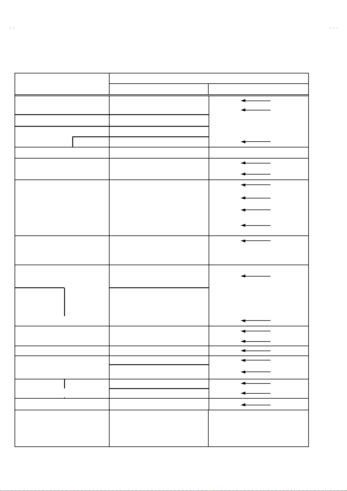
SPECIFICATIONS
/AU
CONT ENTS
AV-21LMT3
AV-21LMG3
/
AV-21LMG3
ITEM
AV-21LTR3 / AV-2105EE
AV-21LT3 / AV-21LT3
Dimen sions( W×H×D) 598mm×468mm×471.5mm
Mass 22kg
TV RF System B/ G, I, D/K B/ G, I, D/K , M
RF Mode PAL / SECAM PAL / SECAM / NTSC3.58 / NTSC4.43
Colour System
VIDEO Mode PAL / SECAM / NTSC3.58 / NTSC4.43
Telet ext System FLOP (Only f or AV-21LTR3) FLOP (Only f or AV-21LMT3)
Pi ctur e Tube
Visible siz e: 51cm measured diagonally
High Voltage 26.5kV±1.5kV(at zero beam current)
Receiving Frequency VHF (VL) 46.25MHz~140.25MHz
VHF (VH) 143.25MHz~423.25MHz
UHF 439.25MHz~865.25MHz
Cable TVs of Mid ( X-Z, S1-S10)
CATV
Super (S11-S20) & Hyper (S21-S41)
bands recei vable
VIF Carrier 38.0MHz
Intermediate
Frequen cy
SIF Carrier
32.5MHz (5.5MHz)
31.5MHz (6.5MHz)
32.0MHz
(6.0MHz)
32.5MHz(5.5MHz) /33.5MHz (4.5MHz)
31.5MHz (6.5MHz)
32.0MHz
(6.0MHz)
PAL (4.43MHz),
Col ou r S ub C arr ier Fr eq uen cy
SECAM (4. 40625MHz / 4.25MHz)
NTSC (3.58M Hz / 4.43MHz)
[AV-21LTR3 / AV-21LT3 / AV-2105EE]
Power Input Rated Volt age
: AC110~240V, 50 / 6 0Hz
[AV-21LT3
/AU
]
AC110~240V, 50 / 6 0Hz
: AC220~240V, 50 / 6 0Hz
Power Co nsumpti on 100W (Max) / 65W(Avg)
Speaker 5cm×12 cm, Oval type×2
Audio Output 3W (monaural )
Aer ial In put Termin al 75Ω Unbalanced
Input
Output
Video 1V
Audio
500mV(rms) (-4dBs), High impedance,
RCA×2 (F ront / Rear)
75Ω (Front / Rear
Video 1V(p-p), 75
Ω
Audio 500mV(rms) (-4dBs), Low impedance,
/-A
Headphone jack
3.5mm mini jack
[AV-21LT3 / AV-21LT3
Remote Control Unit
: RM-C364G Y
[AV-21LTR3]
: RM-C90
(Batter y size : AA / R06 / UM -3×2)
Design and specifications are subject to change without notice.
2
/AU
No. 52030
/ AV-2105EE]
[AV-21LMG 3 / AV-21LMG3
/-A
]
: RM-C364G Y
[AV-21LMT3]
: RM-C90
(Batter y size : AA / R06 / UM -3×2)
Page 3
A
3
A
3
A
SAFETY PRECAUTIONS
V-21LMT3/AV-21LTR
V-21LT3/AV-21LMG
V-2105EE
1. The d esign of th is pr od uct c on tains speci al har d wa re , ma ny
circuit s and components spe cially for safety pur poses. For
con tinu ed pr ot ection , n o c han g es sh ou ld b e ma de to the o rig inal
d esi gn un les s a uth or i zed in wri ti n g by th e ma nu fact ur er .
Replacem en t par ts must b e id ent ic al to thos e u s ed i n th e origin al
ci rcu its. S ervi ce sho uld b e p erfor m ed by qu alif ied p ers onnel
on ly.
2. Alte r ati on s of t he desig n or circui tr y of t he pr od ucts s h oul d not be
made. Any design alterations or additions will void the
manu fact ur er 's warrant y and w i ll f urth er r elieve t he ma nufac tu rer
of r esp onsi b ility for perso nal inj ur y or p rop er ty d am ag e r esult in g
th erefr om.
3. Man y elec tr i cal and mech anic a l p ar ts in th e products have
special safety-related characteristics. These characteristics are
oft en no t e vi den t f r om vis ua l i nsp ection n or ca n t he pr o tect io n
aff or de d by them nece ssarily b e ob tain ed b y us ing rep l acem en t
com po ne nts rated for hig he r voltag e, w att ag e, etc. Rep lacem en t
p arts whic h ha v e th ese s p ecial s afet y ch ar ac t erist ics ar e
ide ntified i n the parts li st of S ervice manua l. El ectric al
components having such features are identified by shading
on t he sche mat ic s and by (!!!! ) on the parts list in Service
manual. The us e of a s ub sti tu te rep lacem en t which do es n ot
h ave th e s ame saf ety ch ar act er ist ics as t he r eco mmen de d
replac em ent part sh own in th e p ar ts list of S er v ice m an ual m ay
cause shock, fire, or other hazards.
4. Do n't shor t between the LIVE side ground and ISOLATED
(NEUTRAL) side ground or EARTH side ground when
repairing.
Some model's power circuit is partly different in the GND. The
diff er enc e of th e GND is s ho wn b y th e LIV E : ( ") side GND, the
ISO LATE D(N EUTRAL) : (#) si de GND and EARTH : ( $) side
GND. Do n't s h or t bet we en th e LIV E sid e GN D an d
ISO LATE D(N EUTRAL) side GND or EART H side GND an d
n ever m ea sur e w it h a mea suri ng appa r atus ( osci l losc op e etc.)
th e LI VE sid e GND an d IS OLA T ED (NE UTR AL ) s ide G ND or
EARTH side GND at the s ame time.
If above note will not b e kept, a fuse or any parts will be broken.
5. If any repair has been made to the chassis, it is recommended
th at t he B1 s et ting shou ld be ch ecke d or adju ste d ( Se e
ADJUST M ENT OF B 1 POW E R SUPPL Y).
6. The hi gh volta ge app lie d t o th e pi ctu r e tube mu st con for m wit h
th at s p ec ifi ed i n S er v ice m an ual. E xcessi ve h igh voltag e ca n
cau s e an i ncre ase in X-Ray em i ssi on , ar c i ng an d possib le
component damage, therefore operation under excessive high
voltage conditions should be kept to a minimum, or should be
preve nt ed. If s evere arc in g occurs, remove t he AC power
immed i ate ly and de termine th e ca use by visua l insp ect ion
(inc or r ect install at ion, cr ac ke d or melte d high volt age har n es s,
p oor so ldering, et c .) . To mai nt ain the p rope r minimu m le v el of
sof t X- R ay emis si on, c omp on en ts in th e hi gh voltag e circui tr y
incl ud i ng t he pic t ur e tu be must be t he e xac t r ep lac em e nts or
alte rn at ives approve d by th e ma nuf act urer of the c omplet e
prod uct.
7. D o n ot c hec k high volt age b y drawi ng an ar c. U se a hi gh volt ag e
meter or a hi g h v ol tag e pr ob e wi t h a V TVM . D i sc ha rg e th e
picture tube before attempting meter connection, by connecting
a cl i p lead to the grou nd frame a nd c onn ectin g th e oth er end of
the lead through a 10kΩ 2W resi sto r to the an od e butt on .
8. W hen se r vice is r equ ir e d, obser v e th e or i gi na l lea d dr ess. E xtr a
prec aut ion sh ou ld b e g i ven t o as sure cor r ec t l ea d dress in th e
high vol tag e ci r cuit a r ea. W here a s hor t ci r cuit h as occu rre d,
th ose co mponent s tha t indic a te evi de nc e of ove r hea ting should
b e r e pl aced. A l wa ys use th e ma nuf act ur er 's r ep lac em en t
components.
9. Isol ation Check
(Safety for Electrical Shock Hazard)
Af ter r e- as s embling th e p r odu c t, alw ays per f orm an is ol at io n
ch ec k on the ex po sed me tal p ar ts of t he c abin et ( a nte nn a
ter m ina ls, video /au dio inpu t and ou tput t erminals, C on trol kn obs,
metal cabin et, screwhe ad s, ea r ph one jac k, con tr ol shaf ts , etc.)
to be s u re the p r odu c t i s s af e t o o pe r ate wi th ou t d an ger of
elect rical shoc k.
(1) Di electric Strength Test
The i so l ati on be tween the AC pr im a ry ci rcu it an d all metal p ar ts
exp osed t o th e us er, p arti c ularly an y expos ed met al p art having a
retu rn p ath to t he chass is s ho ul d withs tan d a vol t age of 3 000V
AC (r.m.s.) for a period of one second.
(. . . . W it hs tan d a vo lt ag e of 110 0V A C (r.m. s .) to an ap plianc e
rate d up to 12 0V , an d 3 00 0V AC ( r .m. s.) to an ap pl i an c e r at ed
200V or more, for a period of one second.)
This meth od of test requires a t est equi pmen t n ot gener ally found
in t he s er vic e trade.
(2) Leakage Current Check
Plug th e AC l in e c ord d irect ly into th e AC ou tlet ( do n ot us e a lin e
isol ati o n transf ormer du ring this ch eck.) . U s in g a " Lea kag e
Curr ent Teste r", me asure th e lea kage cu rr e nt f rom each exp osed
metal p ar t of the c a bi ne t, p art icularly any e xpos ed me tal p art
h avi ng a re turn pa th to t he c h assis , t o a kn ow n go od ea rt h
grou nd (wa ter pi p e, e tc.) . An y l eaka ge curren t m ust n ot e xc eed
0.5mA AC (r.m.s.).
Howev e r, i n tropic al ar ea , th is must no t exc e ed 0.2 mA AC
(r.m.s.).
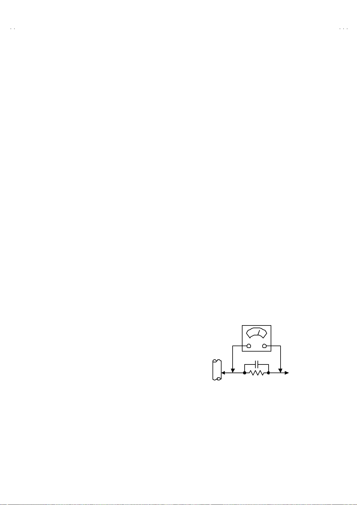
"""" Altern at e Che ck M ethod
Plug th e AC l in e c ord d irect ly into th e AC ou tlet ( do n ot us e a lin e
isol ati o n transformer during t hi s che c k.). Use an AC v o lt me ter
h avi ng 1 000 oh ms pe r volt or m or e sens it ivity i n th e fo llowing
mann er . C on nec t a 1 50 0Ω 10W res ist or para lle le d b y a 0 .1 5µF
AC-type c apa cit or bet ween an ex po sed met al pa rt a nd a kno wn
g ood e ar th gr o un d ( water pi pe , etc.). M eas ure th e AC volt ag e
acr oss th e res ist or with th e AC v o l tm eter. M ove th e r esistor
con nec tion to e ach exp os e d me tal par t, part i cularly a ny exp osed
metal p ar t hav in g a r etu rn pat h to t he chassis, an d measu re th e
AC vol tag e ac ro s s the r es ist or . Now, re ver s e th e plu g in th e AC
ou tl et and r e pe at eac h m ea suremen t. An y volt ag e me as u re d
must no t e xceed 0 .7 5V AC (r .m.s.). This c orre spo nds to 0 .5mA
AC (r.m.s.).
Howeve r, in tropica l area, this must not exceed 0.3V AC ( r.m.s.).
This corresponds to 0.2mA AC (r.m.s.).
AC VOLTMETER
(HAVING 1000 Ω /V,
OR MOR E SENSIT IVITY)
0.15μF AC-T YPE
PLACE THIS PROBE
1500 Ω 10W
GOOD EARTH GROUND
ON E A C H EX PO SE D
ME T AL PA RT
No.52030
3
Page 4
A
V-21LMT3/AV-21LTR3
A
A
V-21LT3/AV-21LMG3
V-2105EE
FEATURES
"
N ew ch ass i s d esign en abl es us e of an i nt eracti ve on-scr ee n c ont ro l.
"
W ide r an ge volt age (110V ~2 40V ) AC p ower input. (Exce pt f or AV -2 1LT3
" W ith AUDIO / VI DEO IN PUT & OUTPUT termina l.
"
MU TING button can red uce th e a udio l evel to zer o i nst ant ly.
" F unct i on al remote co ntr ol t o oper ate T V set (f or ch annel se l ect, v olume c ontrol, p ower ON /OF F , etc. ) f rom a d ist anc e.
"
I2C bu s con tr ol ut ilizes single chi p ICs for IF, V /C, DEF. V SM PRES ET, PRESET & SETUP T OUR.
" By m e ans of AU T O PR OGRA M, the TV s tatio ns c an be s elec te d aut omatic a lly a nd the TV cha nn els c an al so b e r ear r an ge d aut omatic al ly.
" T he TELETEXT SYST EM ha s a built-in F L OP s yst em. (Only f or AV - 21LMT3 / A V-21lLTR3)
"
Bu ilt-in E CO MOD E (ECONOMY, ECOLOG Y)
In acco rdanc e with th e br ig ht ness i n a r oo m, th e br ig ht ness and / of con trast of the p i cture can b e a dj ust ed au tom at ic ally to make th e
op ti mu m pictu re w hi ch is eas y on the e ye.
" Built – in ON TIMER, RETURN + & CHILD LOCK.
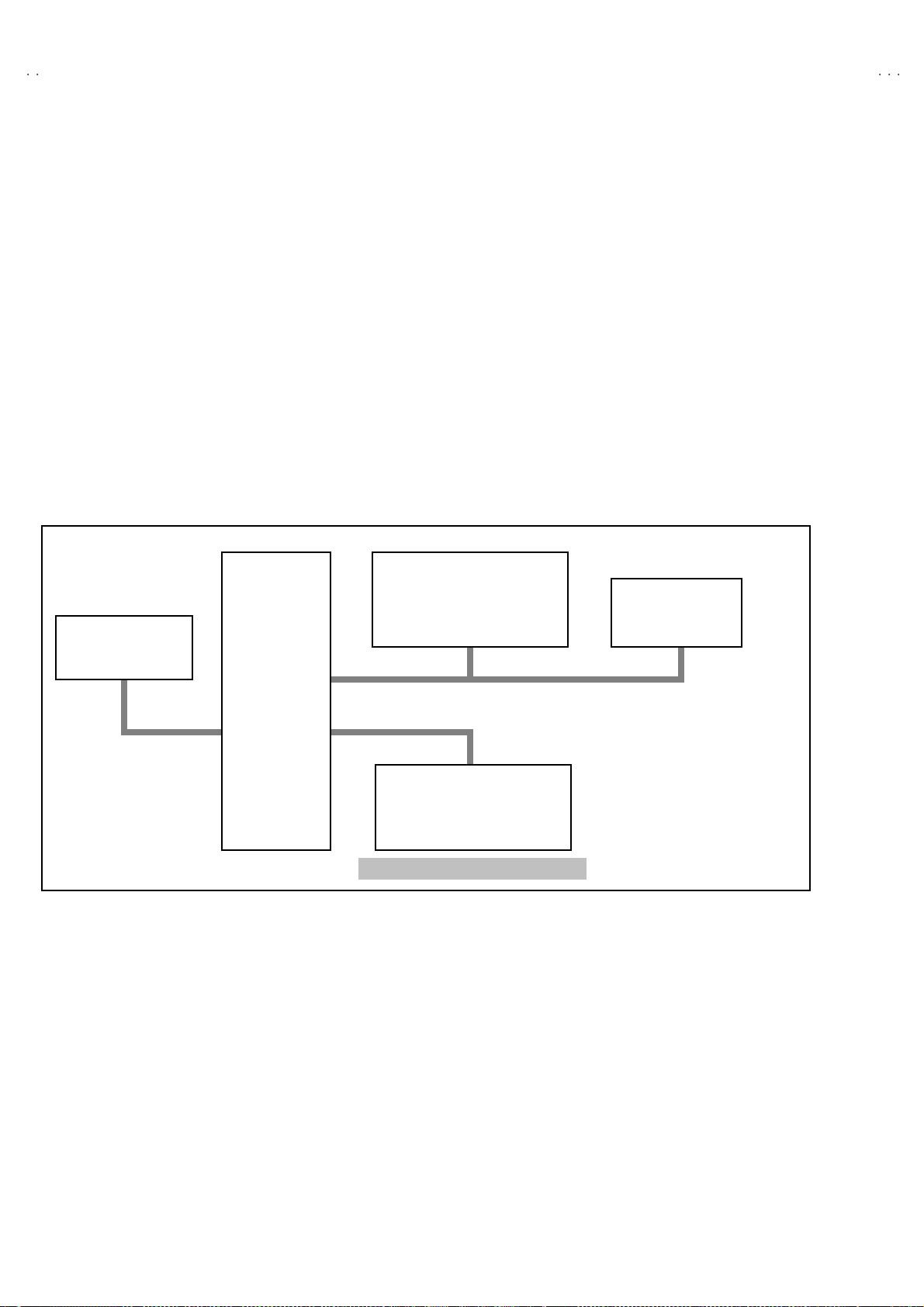
SYSTEM BLOCK DIAGRAM
"
/AU
)
IC702
MEMORY
IC701
SCL2/SDA2 TCL/TDA
MICRO
COMPUTER
IC301
VIDEO/ CHROMA
DECORDER
SCL1/SDA1
IC821
TEXT DECORDER
Only f or AV-21LMT3 / A V-21LTR 3
TU001
TUNER
4
No. 52030
Page 5
A
3
A
3
A
FUNCTIONS
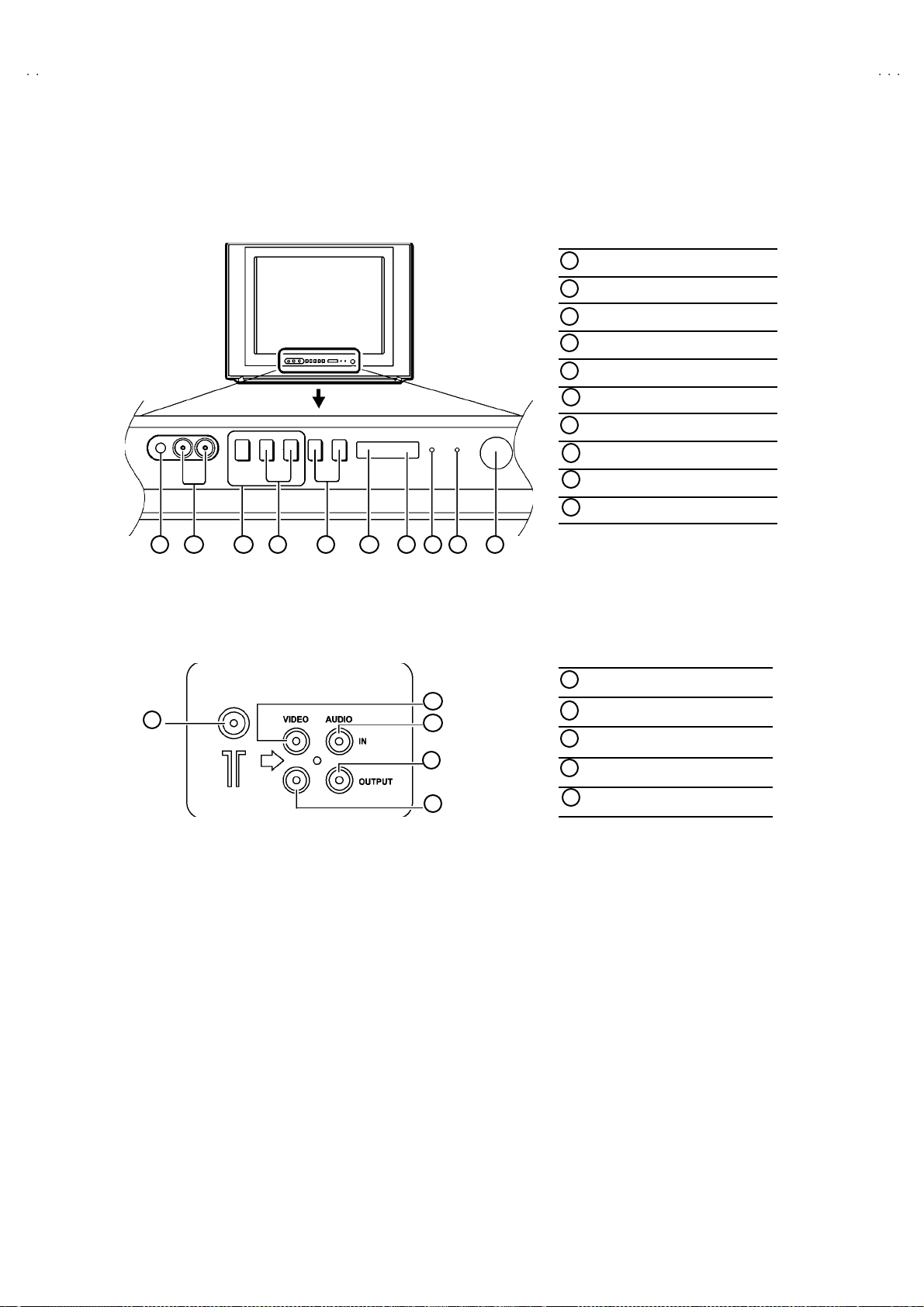
■
FRONT PANEL
MENU buttons
1
CHANNEL -/+ buttons
2
VOLUME -/+ bu tto ns
3
AI ECO s en sor
4
REMO TE CON T R OL s ens or
5
ON TIMER lamp
6
POWER lamp
7
MAIN POWER button
8
A/V INPU T terminal
9
HEAD PHONE j ack
10
V-21LMT3/AV-21LTR
V-21LT3/AV-21LMG
V-2105EE
10 9 1 2 3 4 5 6 7 8
■
REAR TERMINAL
1
ANT Terminal
1
2
3
4
5
VIDEO INPU T Term i nal
2
VIDEO OUTPUT Terminal
3
AUDIO INPUT Termin al
4
AUDIO OUT PUT Terminal
5
No. 52030
5
Page 6
A
V-21LMT3/AV-21LTR3
A
A
V-21LT3/AV-21LMG3
V-2105EE
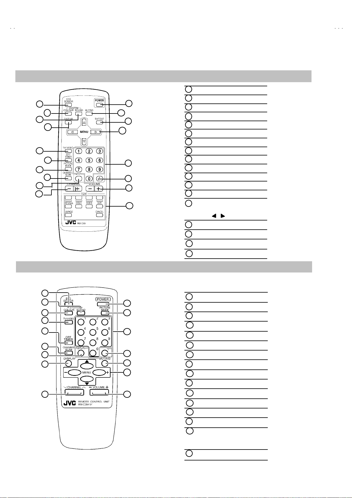
■
REMOTE CO NT ROL UNIT
RM-C90 : AV-21LMT3 / AV-21LTR3
1
2
3
4
5
6
7
8
9
10
12
ECO S ENSOR ke y
1
COLOUR SY STEM ke y
11
13
14
15
16
17
18
2
SOUND SYSTEM key
3
DISPLAY k ey
4
TV/VI DEO key
5
OFF TIMER key
6
PICTURE MODE key
7
CHANNEL SCAN key
8
RETURN+key
9
CHA NNEL -/+ key
10
POWER key
11
MUTING key
12
TV/TEXT key
13
MENU ke y
14
MENU ▲/▼ key
MENU / key
Number (CH.) key
15
-/--
16
VOL UME -/+ key
17
Teletext key
18
key
RM-C364GY : AV-21LT3 / AV-21LT3/AU / AV-21LMG3 / AV-21LMG3/-A / AV-210 5EE
1
2
3
4
5
6
7
8
9
10
11
12
13
14
15
16
ECO S ENSOR ke y
1
SOUND SYSTEM key
2
COLOUR SY STEM ke y
3
TV/V IDEO key
4
OFF TIMER key
5
CHA NNEL SC AN k ey
6
RETURN+key
7
DISPLAY key
8
CHANNEL key
9
POWER key
10
PICTURE MODE key
11
Number (CH.) key
12
-/--key
13
MUTING key
14
MENU ke y
15
MENU ▲/▼ key
MENU -/+ key
VOL UME-/+ key
16
6
No. 52030
Page 7

A
3
A
3
A
MAIN DIFFERENCE LIST
V-21LMT3/AV-21LTR
V-21LT3/AV-21LMG
V-2105EE
Part Name
Model Name
AV-21LM T3 SCG-1316-H2 RM-C90-1H GG10129-025A-H QMPR340-165-K2
AV-21LTR 3
AV-21LT3
AV-21LT3
AV-21LM G3 SCG-1317-H2 GG10129-025A-H QMPR340-165-K2
AV-21LM G3
AV-2105EE
/AU
/-A
Part Name
Model Name
AV-21LM T3
AV-21LTR 3
AV-21LT3
AV-21LT3
AV-21LM G3 LCT1196- 001A-H LCT1197- 001A- H
AV-21LM G3
AV-2105EE LCT1195- 001A-H BT-54012-2
/AU
/-A
Main PWB Remote Control Unit Front Cabinet Power Cord
SCG-1414-H2
SCG-1405-H2 RM-C364GY-1H GG10129-012A-H
SCG-1416-H2 GG10129-027A-H QMPG090-165-K2
SCG-1415-H2 GG10129-027A-H QMPR340-165-K2
Packing Case Inst Book Digest Manual Warranty Card
GG10044-045A-H LCT1174- 001A-H LCT1175- 001A- H
GG10044-047A-H LCT1188- 001A-H
GG10129-026A-H
QMPR380-165-K2
LCT1189- 001A-H
BT-56001-2
Item
Model Name
AV-21LM T3 B/G, I, D/K,M
AV-21LTR 3
AV-21LT3
AV-21LT3
AV-21LM G3
AV-21LM G3
AV-2105EE B/G, I, D/K
/AU
/-A
TV RF System
B/G, I, D/K PAL / SECAM
B/G, I, D/K,M
Co l our S yst em
[RF Mode]
PAL / SECAM
NTSC3.58 / NTSC4.43
PAL / SECAM
NTSC3.58 / NTSC4.43
PAL / SECAM
Interm ediate
Frequency
[SIF C arri er ]
32.5MHz (5.5MHz)
33.5MHz (4.5MHz)
31.5MHz (6.5MHz)
32.0MHz (6.0MHz)
32.5MHz (5.5MHz)
31.5MHz (6.5MHz)
32.0MHz (6.0MHz)
32.5MHz (5.5MHz)
33.5MHz (4.5MHz)
31.5MHz (6.5MHz)
32.0MHz (6.0MHz)
32.5MHz (5.5MHz)
31.5MHz (6.5MHz)
32.0MHz (6.0MHz)
OSD Language
E / R / A / P
E / R
E / C / M / I
E / R / A / P
E / R / U
No. 52030
7
Page 8

A
V-21LMT3/AV-21LTR3
A
A
V-21LT3/AV-21LMG3
V-2105EE
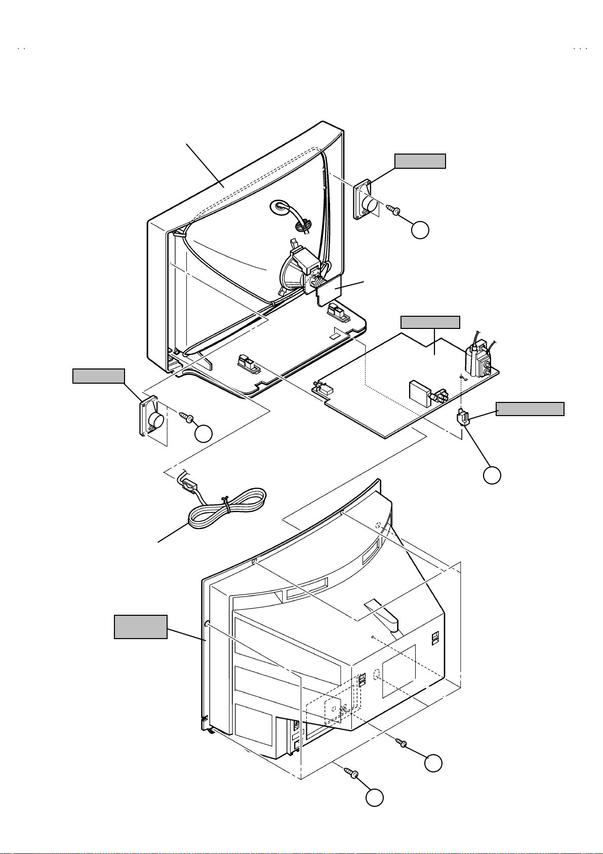
SPECIFIC SERVICE INSTRUCTIONS
REMOVING THE REAR COVER
1. U np lu g t he power plu g.
$$$$
!!!!
.
and a
2. As sh own in f i gur e, remove t he 7 screws marked
screw marked "
3. W ithdr a w t he rear cover to ward you .
".
""
REMOVING THE MAIN PW BOARD
" After removing the rear cover.
1. Sl i ght l y ra is e the b ot h si de s of the M AIN PW BOAR D b y han d
an d r e mo ve t he PWB stop pe r mar ke d #
bottom.
2. W ithdr a w t he MAIN PW BOARD b ackw ar d.
(If necess ar y, ta k e off the wire c lamp, c onn ect or s etc. )
# f ro m t he c abine t
##
REMOVING THE SPEAKER
" After removing the rear cover.
1. As sh own in fi gu r e, remove the 2 scr ews marked
2. F ol low th e s ame s t eps when r em oving the oth er ha nd speak er.
CHECKIN G THE MAIN PW BOARD
1. T o ch eck the ba ck side of the PW B oar d.
1) Pu ll out the MA IN PW Bo ard. ( Ref er to RE MO VING THE MAIN
PW B oar d)
2) Er ect th e PW Boar d vert ic ally so th at you can easi l y c h eck th e
b ack side of th e PW Boar d.
[CAUTION]
"
W hen ere cti ng th e PW Boar d, be c ar ef ul s o that there w ill b e n o
con tact in g wi th other PW Board.
"
Before turning on power, make sure that the CRT earth wire and
oth er co nne cto r ar e p r ope rly c onn ect ed.
WIRE CLAMPIN G AND CABLE T YING
1. Be sure t o cl amp th e wire.
2. N ever remo ve th e c able tie used f or ty i ng th e wi re s to ge ther.
Sh oul d i t be inad verte ntly r em ove d, be su re to ti e th e wires w it h a
new cable tie.
8
No. 52030
Page 9
A
3
A
3
A
FRONT CABI.
SP EAKER
CRT SOCKET
PWB
MAIN PWB
V-21LMT3/AV-21LTR
V-21LT3/AV-21LMG
V-2105EE
D
××××
(
2)
SP EAKER
POWER
CORD
REAR
COVE R
(×××× 2)
D
PWB STOP PER
C
××××
(
1)
B
A
(×××× 7)
No. 52030
9
Page 10
A
V-21LMT3/AV-21LTR3
A
A
S
U
/C
NUMBERS
U
U
V-21LT3/AV-21LMG3
V-2105EE
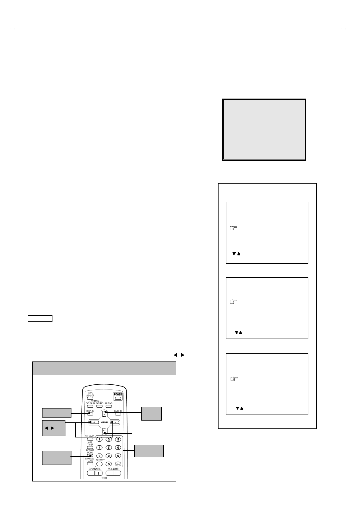
REPLACEMENT OF MEMORY ICs
1. MEMORY ICs
Thi s mod el u ses me mo r y I Cs. This me mo r y IC da ta are f or pr o per oper a tion of th e vide o and deflec t io n cir cuits.
When r ep la cing memory ICs , b e su r e to use ICs w r it ten w i th t he ini tial v a lu es of dat a.
2. PROCEDURE FOR REPLACIN G MEMORY ICs
(1) Power off
Switch the p ower of f and di sc o nn ect t he pow e r plu g f rom t he w al l out let.
(2) Replace ICs
Be sure to use memo ry ICs written with the init ial data values.
(3) Power on
Connect th e pow er plu g i nt o the wal l ou tl et and s w itch t he po we r on .
(4) C heck and s et SY STEM CO NSTA NT SET
・・・・ It must not adjust w ithout adjustment signals.
1) Press th e DI SPLAY key and the PICTURE MODE key of the REMOTE
CONTROL UNIT simultaneously.
2) The SERVICE MENU screen of Fig. 1 will be displayed.
3) W hi l e th e SE RV IC E M EN U is di splay ed , again press the DI SPLAY ke y and
PICTURE MODE ke y si m ulta neo usl y, an d t he S YSTEM CONSTA NT SE T
screen of Fig. 2 w ill b e di splayed.
4) Check the s ettin g val ue s of the S YSTE M CO N STANT SET of T able 1 If th e
val u e is diffe re nt, select the sett ing item with the MENU ▼/▲key, and set
th e co rrect valu e with t he MENU - / + k ey.
5) Press the DISPLA Y key twi c e, and r etu rn t o the n or m al sc r ee n.
(5) Receive channel of setting
Refe r to th e OPE RATI NG I NST RUCTIONS an d set th e r ece ive cha nn el s
(chan nels prese t) as descr i be d
(6) User Setting
Check t he us er s etti n g v alu e of T ab l e 2, a nd if setti ng v al ue is di f fer en t, set
th e co rrect valu e.
For setting , refer to the OPE RATI NG INSTRUCTIO NS.
(7) Setting of SERVICE MENU
Ve rif y the s et ting it ems of th e SE RVIC E M ENU, and reset w he r e n ecessa r y.
For setting , refer to the SERVICE ADJUSTMENTS.
NOTE
Alth ou gh th e k ey p osi tion of t he RM-C90 re mote control unit is diff erent fr o m
th at of t he RM-C36 4GY remot e con trol unit, th e function s of bo th units are the
sam e So pl e as e use th e attac hed d iagram for t he RM-C90 remote control
uni t fo r the R M-C36 4GY.
By t he way, MENU -/ + Key fu nction s in t he sam e ma nn er as for / key.
1.IF 2.V
3.DEF 4.VSM PRESET
5.PRESET
6.SETUP TOUR OFF
1-6 SELECT DISP : EXI T
******
****** *****
************
SYSTEM CONSTANT SE T 1
: SELECT
- / + : OPER ATE DISP : EXIT
SYSTEM CONSTANT SE T 2
ERVICE MEN
***** **
* *.****
* * * *
****
********
** ***
** ***** ***
**********
*** ** **
*** ** ** ** ***
*** ** ***** ** **
Fig.1
SY STEM C ON STA NT- ⅠⅠⅠⅠ
COL O UR :
BILIN GUAL : N O
NE R : M
T
ECO SENSOR : YES
LANG U AG E :
/
***
***
SY STEM C ON STA NT- ⅡⅡⅡⅡ
B/B SO UND :
LOCK : 180
COL OUR AU TO :
QSS : MINT
ALC : NO
TEXT R ATE : 2 0
: SEL - / + : OPE DISP : EXIT/
***
***
SY STEM C ON STA NT-
ⅢⅢⅢⅢ
10
KEY ASSIGNMENT OF REMOTE CONTROL UNIT
DI SPL A Y k ey
MENU
/ key
PICTURE
MO DE k e y
MENU
▼/▲
key
(RM-C90)
key
No. 52030
SYSTEM CONSTANT SE T 3
AMP TUNER : NO
VNR : YES
TEXT TABLE :
VOLUM PWM : POS
: SEL - / + : OPE DISP : E XIT
/
Fig.2
***
Page 11

A
3
A
3
A
SE TT ING OF SY STEM C ON STANT SET
A
Setting item Setting contents
AV-
21LMT3
AV-
21LTR3
AV-
21LT3
Setting value
AV-
21LT3/AU
AV-
21LMG3
V-21LMT3/AV-21LTR
V-21LT3/AV-21LMG
V-2105EE
AV-
21LMG3/-A
AV-
2105E E
COLO UR
BIL INGUAL
TUNER
AI ECO S ENSOR
LA NG UA G E
B/B SOU ND
LO CK
COLO UR AUTO
QSS
ALC
TEXT RAT E
AMP TUNER
VNR
TEXT TABLE
VOL UM PW M
MUL TI .
TRIPLE
PA L
YE S NO
MU
MA
YE S NO
E/R/A /P
E/C/ M/I
E/R
E/R/U
ON OFF
YES 10 20
~
25 0 2 40 230 ~
YE S NO
MI NT MQ SS
YE S NO
10 20 40 80
YE S NO
YE S NO
RA CYL
POS
NEG
TRIPLE
MU L T I
NO
MU
YE S
E/R/A /P E/R E/C/ M/I E/R/A /P
OFF
18 0
NO
MI NT
NO
20
NO
YE S
ARA CYL
POS
Table 1
. . TRIPLE
E/R/U
ON OFF
YE S NO
USER SE T TING V ALU ES
Setting item Setting value Setting item Setting value
SUB POWER ON LANGUAGE ENGLISH
CHA NNEL PO SITIO N 1 PO SITIO N CHA NNEL P RE SET Refe r t o OPE RATIN G I NS TRUCT ION
VOL UME About 10 AI ECO S ENSOR OFF
TV/V IDEO
ON SCR EEN DI SPLAY
TV VNR OFF
POSITION INDICATION AUTO SHUTOFF OFF
COLO UR SYSTEM PAL ON TIMER PR1 0:00
SOUND SYSTEM B / G BLUE BACK OFF
OFF TIMER OFF OSD.Shows 00 CHILD LOCK OFF
PICTURE MODE (VSM) BRIGHT SETUP TOUR ON
Table 2
No. 52030
11
Page 12

A
V-21LMT3/AV-21LTR3
A
A
)
)
V-21LT3/AV-21LMG3
V-2105EE
INITIAL SETTING VALUE OF SERVICE MENU
1. Ad ju st men t of t h e SERVIC E M EN U is made o n th e bas is o f the initial s etting va lues ; h owev er, t he new setting va lues w hi ch
set the scree n in its optim um condition may differ from the initial setting.
2. Do not change the initial Setting Values of the Setting (Adjustment) items not listed In “ADJUSTMENT”.
2. V/C
Initial set ting v al ue
Setting item
2. DRI VE
3. BR IG HT
Colour sy stem
RED
GREE N1. CUT OFF
BL UE
RED
BL UE
Variabl e
range
-128 ~+127
-128 ~+127
-127~+127
PA L SE CAM NT SC 3. 5 8 NT SC 4.4 3
0
0
0
4. CONT .
5. COLOUR -63~+63 0
TV
6. TINT
7. SECAM BL ADJ . -31~+31
8. SHARP
3. DEFLECTION
1. VER. POS ITION -04 ~ +03 -1 -3
2. HOR. POSITION
3. VER. HEIGHT
4. VE R . L INE AR ITY
5. VER. SWCURVE
6. H OR. V C O AD J UST
VI DEO
Do Not Ad j.
Setting item Variabl e range
MATSUSHITA
MURATA
TV - 5(Fixe d
VI DEO
Do Not Ad j.
-63 ~+63
-63 ~+63
-32~+31
-16 ~ +15
-64 ~ +63
-32 ~ +31
-32 ~ +31
-63 ~ +62
0
0 0
+5 0
+8 0
0
+15(Fixed
Initial set ting v al ue
fv : 50Hz MODE fv : 60Hz MODE
+3 +3
-35 +1
+15 -1
-32 +0
+0 +0
4. VS M PRESE T
12
VS M pr eset
VSM mode
Setting item
TINT SETTING VA LUE +1 5
COLOUR SE TTIN G VA LUE +15
BR IG HT SET TING VA LUE +1 5
CONT . SE TTING VA LUE +30 +15 +11
SHARP SE TTIN G VA LUE + 1 5 +1 2
BRIGHT STANDARD SOFT
No. 52030
Page 13

A
3
A
3
A
5. PRESE T
The items in the following table, it is no requirem ent for adjustment.
If va lues had changed by t he miss operation, se t the initial settin g v alue s i n the f ollo wing table.
Colour Sy stem Do Not Adju st
V-21LMT3/AV-21LTR
V-21LT3/AV-21LMG
V-2105EE
Setting item
1. C TRAP FIX 1 1 1 1
2. SHARP PEAK 0 0 0 0
3. A BL 1 1 1 1
4. GAMMA 0 0 0 0
TV 0 2 2 3
5. Y. DELAY TIME
VI DEO 0 2 0 2
6. BL AC K EX P STAR T
TV 1 1 0 0
7. C-BPF
VI DEO 1 1 1 1
8. CW / SC P 0 0 0 0
9. VIF DET LEVEL 0 0 0 0
11. IF AGC MIN 0 0 0 0
12 . VIF AGC 0 0 0 0
13. VIF PM OD 0 0 0 0
19 . VN R 15 15 15 15
PA L S E CAM NT SC 3.5 8 NT SC 4.4 3
+3 +3 +3 +3
Initial set ting v al ue ( Fix ed v alue)
20 . R GB LIM 1 1 1 1
21. RGB LIMIT LEVEL 2 2 2 2
23. TEXT H. POS ITION -3 -3 -3 -3
24. READ DATA
Sound System D o Not Ad j u s t
Setting item B/G I D/K M
10. SIF DET L EVEL +0 +0 +0 +0
14. SIF BP F BW ADJUST
15. SIF TRAP FO ADJUST +0 +0 +0 +0
16. SIF TRAP FO ADJUST 2 +0 +0 +0 +0
17. SIF -TRAP 0 0 0 0
18. SIF -BPF 1 0 0 0
22 . SIF SW 0 1 1 1
+
0
+
0
+
0
+
0
No. 52030
13
Page 14

A
V-21LMT3/AV-21LTR3
A
A
V-21LT3/AV-21LMG3
V-2105EE
REPLACEMENT OF IC301 (IF V/C DECODER)
" For the IC 301(I F V/C DEC ODER) of this mode l, a ll data are written in the micr o-computer. So, wri te the data in the micro-
computer in accordance with the following procedures before starting adjustment.
PROCE DURES
(1) T ur n t he POW E R O F F.
(2) R ep lace t he IC 30 1 w ith a n ew o ne .
(3) W hil e pr essi ng ME NU bu tto n a nd VO L+ bu tto n ON the FRO NT CABIN E T simul t ane ous ly, turn th e POW ER O N. Wh en th e POWER is
turn ed ON, th e d at a is w ritten in the m icro-compute r immed iately.
LOCATI ONS OF FRONT PANEL BUTTONS AND LAM PS
MENU buttons
MENU buttons
1
1 2 3 4 5 6 7 8
CHANNEL ・ / ・ buttons
CHANNEL -/+buttons
2
(ME NU ・ / ・ bu tt ons)
(ME NU -/+butto ns)
VOLUME -/+ buttons
VOLUME -/+ buttons
3
(MENU -/+ bu tto ns)
(MENU -/+ bu tto ns)
AI ECO sensor
AI ECO sensor
4
REMOTE CONTROL sensor
REMOTE CONTROL sensor
5
ON TIMER lamp
ON TIMER lamp
6
POWER lamp
POWER lamp
7
MAIN POW ER but ton
MAIN POW ER but ton
8
14
No. 52030
Page 15

A
3
A
3
A
SERVICE ADJUSTMENTS
BEFORE STARTING SERVICE ADJUSTMENT
1. There ar e 2 w ay of ad ju s ti ng t hi s T V: One i s wi t h the
REMOTE CONTROL UNI T and the other is the conventional
method using adjustment parts and components.
2. The adjustment with the REMOTE CONTROL UNIT is made
on the basis of t he initia l se tting v alue s. T he setting values
which adjust the screen to its optimum condition may differ
from t he initia l s etting values.
3. Make s ur e th at conn ect i on i s c orr ect l y ma de t o AC p ow er
source.
4. Turn on t he p ower of th e set an d eq uipm en t bef ore us e, an d
start t he adju stm en t proc edure s af ter waitin g at least 30 min utes.
5. U nless ot her w i se spec if i ed, p rep are th e mo s t suita bl e r ec epti o n
or inp ut si gn al for adj ust m ent.
6. N ev er t ouch a ny adjus tme n t part s, whi ch ar e n ot spe cif ied
in t h e li st f or thi s adjustme n t VRs , tra nsf or ms, c onde nser s,
etc.
7. Prep aratio n for ad justment
Unless oth erwis e specified in the adjustment instructions, preset
the following functions with the REMOTE CONTROL UNIT.
User mode positi on
PICTURE MODE (VSM) BRIGHT
VNR OFF
TINT / COLOUR / BRIG HT
CONT. / SHARP
BLUE BA CK OFF
OFF TIMER OFF
AI ECO S ENSOR OFF
AUTO SHUT OFF OFF
V-21LMT3/AV-21LTR
V-21LT3/AV-21LMG
V-2105EE
CENTER
MEASURING INSTRUMENT AND FIXTURES
1. DC voltmeter (or digital voltmeter)
2. Oscilloscope
3. Si gn al g en erat or (P att er n g ener at or) [ PAL / S EC AM / NT S C]
4. Remote control unit
ADJUSTMENT ITEMS
Adjustment it em Ad just ment item
B1 POW E R SUPPLY
FOCUS adjustme nt VSM P RESET setting
IF ci rc uit a djust ment
V/C (Video / Chroma) circuit adjustment
DEFLECTION c ircuit adjustment
PURITY/ CO NV ER GEN C E adj us tm ent
No. 52030
15
Page 16

A
V-21LMT3/AV-21LTR3
A
A
3
V-21LT3/AV-21LMG3
V-2105EE
BASIC OPERATION OF SERVICE MENU
"
The adjustment using SERVICE MENU
The f ollowi ng adjus tme nt it ems u se t he SE RV ICE MENU in the ser i es of the adju stment . The adjustm ent s are made on the bas is of the
initial s e tting val u es. The ad ju stm ent valu es whic h ad ju st t he scr een to th e o ptim um co ndit io n c an be diffe rent from the i n iti a l sett in g values.
With th e SER VICE ME NU, various s ett in gs c an be made , a nd the y are broa dl y c l ass ifi e d i n the f ollowin g ite ms of s etti n gs.
1.I F ・・・・・・・・・・・・・・・・・・・・ ・・・ Adjustmen t of th e IF ci rcuits.
2.V /C ・・・・・・・・・・・・・・・・・・・・・・ Ad ju stmen t of th e VID EO /CH RO MA circui t.
3.DEF ・・・・・・・・・・・・・・・・・・・・ ・ Adjustm ent of the DEFL ECTION circ uit.
4.V SM PRES ET ・・・・・・・ ・・・・・ Ad ju stmen t of th e init ia l sett in g va lue s of VSM cond it i on as STA NDARD, SOF T a nd BR IGHT.
(VSM : Video Status Memory)
5.PRESET
6.SETUP TOUR OFF ・・・・・・・・ It s hou l d be abl e to s elect mode (LANGU AG E a nd AU TO CH PRESE T).
"
Key operation of the SERVICE MENU
[Enter to SERVICE MENU]
Press the DI SPLAY key and the PICTURE MODE key of the REMOTE CONTROL
UNIT s imult an eou sly. Th en enter the S ERVICE ME N U mod e as sh own in Fig.1 .
[Exit from SERVICE MENU]
When complete th e ad just ment w or k, press th e DI SPLAY key to r eturn t o th e
SERV ICE MENU.
An d th en pr es s the DISPLA Y ke y ag ain, retur n to the n or m al sc r een .
[ Se lec t fr o m SE RV IC E ME NU ]
In SER VI CE M ENU, pr ess t he n umber ( 1 ~6) ke y of th e r emo te c ont ro l un it , to select
an y of th e ad j ustm en t ite ms.
The colours w hi ch se le cte d i te m ch aract ers are ch ang ed.
・・・・・・・ ・・・・・・・・・・
Adjustment of the RF circ uit [Do not adjust].
[Shou ld be O FF].
SE RVICE M EN U
1.IF 2.V/C
.DEF 4.VSM PRESET
5.PRESET
6.SETUP TOUR OFF
1-6 SELECT DISP : EXI T
******
****** *****
***** **
************
* *.****
**********
* * * *
*** ** **
*** ** **** ***
*** ** ***** ** **
** ***
** ***** ***
Fig.1
****
********
KEY ASSIGNMENT OF REMOTE CONTROL UNIT
DI SPL A Y k ey
MENU
/ k ey
PICTURE
MO DE k e y
MENU
key
▼/▲
NUMBERS
key
(RM-C90)
KEY ASSIGNMENT OF REMOTE CONTROL UNIT
DI SPL A Y k ey
MENU
-/+key
PICTURE
MO DE k e y
NUMBERS
key
MENU
▼/▲ key
(RM-C364GY)
16
No. 52030
Page 17

A
3
A
3
A
[Method of setting]
1. IF
[1. VCO]
① 1 Key ・・・・・・・ ・・・・・・・・・・・・・ ・・・・・ Select 1.IF.
② 1 Key ・・・・・・・ ・・・・・・・・・・・・・ ・・・・・ Select 1.VCO
③ The VCO (CW) screen will be displayed a allow mark when the AFC voltage is at a certain level.
④ DISPLA Y Key・・・・・・・ ・・・・・・・・・・・ As you press this key twice, you will return to the SER VIC E ME NU.
[2. DELA Y P OINT]
① 1 K ey・・・・・・・ ・・・・・・・・・・・・・ ・・・・・ Select 1.IF.
② 2 K ey・・・・・・・ ・・・・・・・・・・・・・ ・・・・・ Select 2.DELAY P OINT.
③ ME NU - /+ K ey ・・・・・・・ ・・・・・・・・・・ Set (ad just) th e se tting valu es o f th e settin g it ems.
④ DISP LAY Key・・・・・・・ ・・・・・・・・・・・ W hen th is is pr esse d twice, you will r et urn t o the SE RV ICE MENU .
2.V /C, 3.DEF and 4 .VSM PR ES ET
① 2~4Key ・・・・・・・ ・・・・・・・・・・・・・ ・・・ Select one from 2. V/C , 3. DEF an d 4. VSM PRE SET.
② MENU ▼/ ▲ Key ・・・・・・・・・・・・・・ Select setting items.
③ MENU -/+ Key ・・・・・・・ ・・・・・・・・・・ Adj u st th e va lues of t he i tem s.
④ DISPLA Y Key ・・・・・・・ ・・・・・・・・・・・ W hen this is pr esse d, re turn t o t he SE RVICE M EN U.
V-21LMT3/AV-21LTR
V-21LT3/AV-21LMG
V-2105EE
6.SETUP TOUR
① B y pressing th e 6 key, you can ch ange t he ON or OF F ( should be OFF).
(Should be OFF)
%・
The JVC’s logo will be shown about 15 seconds automatically.
② MENU -/+ Key ・・・・・・・ ・・・・・・・・・・ Select Language.
③ MENU ▼ Key・・・・・・・ ・・・・・・・・・・ Au to Se arch.
If it is ON, th en you tu rn the TV power off, w h en you are t ur n t he TV p ower o n a gain .
No. 52030
17
Page 18

A
V-21LMT3/AV-21LTR3
A
A
S
U
6.SETU
JUS
6.SETU
ON /
50
(R)
50
O
V-21LT3/AV-21LMG3
V-2105EE
SERVICE MENU FLOW CHART
SE RVICE M EN U
ERVICE MEN
1.IF 2.V/C
3.DEF 4.VSM PRESET
5.PRESET
P TOUR OFF
1-6 SELECT DISP : EXI T
******
****** *****
***** **
* *.****
************
**********
*** ** **
*** ** **** ***
*** ** ***** ** **
P TOUR
* * * *
****
********
** ***
** ***** ***
FF
(By pr essi ng 6- ke y)
OFF
SU B ME NU 1. I F
IF
1. VCO
2. DELAY POI NT
1-2 : SELECT DISP : E XIT
SU B ME NU 2. V /C
V/C PAL
1. CUTOFF
(G)
(B)
50Hz
/ :SELECT
- / + : OPERATE DISP : EXIT
* **
* **
* **
VCO (CW)
TOO HIGH
ABOV E REFERENCE
JUST REF ERE NCE
BELOW REF ERE NCE
TOO LOW
AFT AD
VCO ADJUST
FINE
AGC TAKE- OVER
- / + : OPERATE DISP : EXIT
***.**
T
DELAY POINT UHF
MH z
** *(* *)
** *(* *)
** *(* *)** *(* *)
** *(* *)
** *(* *)
** *(* *)** *(* *)
DISP : EXIT
**
SU B ME NU 3. D EF
DEF
1. VER. POSITION
/ :SELECT
- / + : OPERATE DISP : EXIT
PAL
**
Hz
SUB ME NU 4. V SM PR ES ET
BRI GHT
TINT
COLO UR
BRI GHT
CONT.
SHARP
/ :SELECT
- / + : OPERATE DISP : EXIT
**
**
**
**
**
SUB ME NU 5. P RE SET
18
PRESET
PAL
1. C-TRAP FI X
Hz
/ :SELECT
- / + : OPERATE DISP : EXIT
B/K
*
No. 52030
Page 19

A
3
A
3
A
ADJUSTMENT LOCATIONS
V-21LMT3/AV-21LTR
V-21LT3/AV-21LMG
V-2105EE
TOP
MAIN PWB
F901
CRT SOCKET PWB
TP-47R /G
TP-47G /R
T
IC701
(SOLDER SIDE)
U
TP-47B
TP-E
E1
CRT EARTH WIRE
(BRAIDED ASS'Y)
FRONT
IC702
MEMORY IC
DEG
PW
IC821
S
[Only for AV-2 1LMT3 / AV-2 1LTR3]
IC301
TU00 1
T
1
S
1Pin TP-91(B1)
2Pin NC
HV
U
HVT
UPPER:FOCUS
LOWER:SCREEN
3Pin X-ray2
4Pin X-ray1
5Pin TP-E( )
No. 52030
19
Page 20

A
V-21LMT3/AV-21LTR3
A
A
)
adjust
V-21LT3/AV-21LMG3
V-2105EE
ADJUSTMENTS
B1 POW ER SUPPLY
Item
Check of
B1 Powe r
Measuring
instrume nt
Signal
gener ator
Supply
DC Vo lt meter
FOCU S ADJUSTMENT
Item
Ad j ust men t
of FOCUS
Measuring
instrume nt
Signal
gener ator
IF CIRCUIT ADJUS TMENT
Item
Measuring
instrume nt
Test point Ad justment part Description
TP-91 ( B1)
####
TP-E (
)
1. Inp ut a wh ole black sig na l.
2. Connect a DC volt meter to TP-91(B1) and TP-E (#).
3. M ake sure t hat the vol t age i s DC1 16.5±2.0 V.
Test point Ad justment part Description
FOCUS VR
[In HV T]
1. Input a cross-hatch signal.
2. W hil e watch ing the scr e en, adjust the FOCUS VR to make the
ver ti cal and ho rizo ntal l in es as f in e a nd sharp as possi b l e.
3. M ake sure t hat whe n the s creen is d arkened, the l i nes rem ain in
g ood focu s.
Test point Ad justment part Description
Ad j ust men t
of VCO(CW
Signal
gener ator
Remote
control unit
VCO (CW)
TOO HIGH
AB OVE REFEREN CE
JU ST REF ER ENCE
BEL OW R EFERE N CE
TOO LOW
AFT AD JUST
VCO ADJUST
FINE
DISP : EXIT
ADJUSTMENT AT THIS POINT IS USELESS
***.**
MHz
** *(* *)
** *(* *)
** *(* *)** *(* *)
** *(* *)
** *(* *)
** *(* *)** *(* *)
ADJUSTMENT POINT
1. VC O
YE LLOW
Do not
TOO HIGH
ABOVE REFERENCE
J US T R E FE RE NC E
B ELO W RE F E RE NC E
TOO LOW
●Please use signal generator which is correct proof about the
sen ding fr eque nc y.
1. Inp ut th e PA L f ull col o ur b ar (2 10 .2 5MHz) s ig nal .
2. En ter th e SER VICE ME NU.
3. Se lect 1.IF f rom the SERV ICE MENU.
4. Press 1 key and s elect 1.VCO.
5. Select VCO ADJUST with MENU ▲/▼ key.
6. Press MENU -/+ key until the colour of the characters TO O
HIGH ch an ges b lue to yellow . Th en gr ad ually pr ess th e MENU
-/+ key u ntil the TOO LOW ch ang es yellow . At thi s t ime, conf ir m
th at t he val u e of VCO ADJUST is n ear + 00 .
7. Select AFT ADJUS T with MENU ▲/▼ key.
8. Press MENU -/ + key until the characters JUST REFERENCE
ch ang es bl ue to y ellow.
9. Press the DI SPLAY key three times to return to normal screen.
20
No. 52030
Page 21

A
V-21LMT3/AV-21LTR
3
A
3
A
(
)
V-21LT3/AV-21LMG
V-2105EE
Item
Ad j ust men t
of DELAY
POI NT
(AGC)
Measuring
instrume nt
Signal
gener ator
Remote
control unit
DELAY POINT UHF
AGC TA KE-OVER
- / + : OPERATE DISP : EXIT
Test point Ad justment part Description
**
DELAY P OINT
(AG C TAKE-O VER)
1. Inp ut a bl ac k an d wh it e sign al (col o ur of f).
2. En ter th e SER VICE ME NU.
3. Select 1. IF f rom t he SERVI C E M EN U.
4. Select 2 . DELAY P OINT b y pr essi n g the 2 key on the remote
control unit.
5. Se t th e in it i al sett i ng v alue s of th e se tting item s as sh own b ellow
tabl e.
6. Then adjust the MENU - or + key until video noise disappears.
7. T ur n to oth er ch an nel s and m ake sure th at the r e ar e n o
irregularities.
Setting It e m Va riabl e range Initial set ting v alue
DELAY P OINT
(AGC TAKE OVER)
NT SC 3.5 8
OTHER
0~127
ALPS
QAU0282-001
47
35
No. 52030
21
Page 22

A
V-21LMT3/AV-21LTR3
A
A
(B)
V-21LT3/AV-21LMG3
V-2105EE
VIDEO / C HROM A CIRCUIT ADJUSTMENT
The setting (adjustment) usin g the REMOTE CONTROL UNIT is made on the basis of the initial setting values.
The setting values which adjust the screen to the optim um condition can be different from the initial setting values.
Do not c hang e the initial setting v alue s of the sett ing items not liste d in “A DJUSTMENT”.
Item
Ad j ust men t
of WHITE
BALANCE
(Low light)
Measuring
instrume nt
Test point Ad justment part Description
Signal
gener ator
Remote
control unit
V/C PAL
1. C UTO FF
50Hz
/ :SELECT
- / + : OPERATE DISP : EXIT
(R)
(G)
(B)
* **
* **
* **
KEY ASSIGNMENT OF REMOTE CONTROL UNIT
CU TO FF O F F
(H.LINE OFF)
CU TO FF O N
(H.LINE ON)
R. CUTOFF( )
R. CUTOFF( )
▲
▲
R. DRI VE( )
▼
R. DRI VE( )
▼
123
4
7
56
8
9
RGB
1. CUT OFF (R)
CUT OFF (G)
CUT OFF (B)
SCREEN VR
[IN HVT]
G .C UTOFF ( )
B. C UTOF F( )
B. D RIV E( )
B. C UTOF F( )
B. D RIV E( )
G .C UTOFF ( )
▲
▲
▲
▲
▲
▲
1. Inp ut a bl ac k an d wh it e sign al (col o ur of f).
2. En ter th e SER VICE ME NU.
3. S elect 2. V/C from the SERVICE MENU, then selec t 1 . CUT OFF
(R), (G) and (B) .
4. Set each value to initial setting value with 4~9 keys of the
remote control unit.
5. Press the 1 key of th e remote contr ol un i t to sh ow th e s ingle
horizontal line on screen.
6. T ur n t he SCREEN VR fully counter-clockwise, then slowly turn it
cl ockw is e to where on e of a red , bl u e or gr e en c o l our is f aint l y
vis ible.
7. Use keys 4~9 of th e r em ote c ontrol unit an d ad ju st the oth er 2
col o ur s which e x cept th e ap pea r ed col o ur to whe r e th e s in gl e
h oriz o nt al l in e app ea rs whit e.
8. Turn the SCREE N VR to where t he s in gle h or iz ont al line glows
fain tly.
9. Press the 2 key to turn of f th e single horizontal line.
10. Press the DISPL AY key t wi ce to r eturn to th e normal screen.
Adjustment it em
R
G
Variabl e
range
-128 ~+127
-128 ~+127
Initial set ting
value
0
01. CUT OFF
B -128~+127 0
Ad j ust men t
of WHITE
BALANCE
(Hi gh light)
Signal
gener ator
Remote
control unit
2. DRI VE (R
DRI VE ( B)
)
1. Inp ut a bl ac k an d wh it e sign al (col o ur of f).
2. En ter th e SER VICE ME NU.
3. S elect 2. V/C from the SERVICE MENU.
4. Select 2. DRIVE (R) / (B) with MENU ▼/▲ key, and set each
val u e to ini tial setti ng val u e with 4 and 7 or 6 an d 9 k eys of th e
remote control unit.
5. Use the keys 4 and 7 or 6 and 9 t o p ro duc e a white sc r een
V/C PAL
* **
2. D RIV E
50Hz
/ :SELECT
- / + : OPERATE DISP : EXIT
(R)
* **
22
6. Press the DISPLAY key t wice to r etu rn to th e n omal scr een.
Adjustment it em
Variabl e
range
R - 128~+127 +0
2. DRIVE
B
-128 ~+127
No. 52030
Initial set ting
value
+0
Page 23

A
V-21LMT3/AV-21LTR
3
A
3
A
V-21LT3/AV-21LMG
V-2105EE
Item
Ad j ust men t
of
SUB BRIGHT
Ad j ust men t
of
SUB CONT.
Ad j ust men t
of
SUB
COLOUR ⅠⅠⅠⅠ
Measuring
instrume nt
Remote
control unit
Remote
control unit
Remote
control unit
Test point Ad justment part Description
3. BR IG HT 1. R eceiv e an y broadc ast.
2. En ter th e SER VICE ME NU.
3. Select 2. V/C f rom S ERVIC E MENU.
4. Select 3. BRI GHT with the MENU ▼/▲key.
5. Set the initial sett ing value wit h the MENU - / + key.
6. If the brightness is not the best with the initial set value, make
fine adjustment until you get the best brightness.
4. CONT . 1. Rec ei ve any br o adc ast.
2. En ter th e SER VICE ME NU.
3. Select 2. V/C f rom S ERVIC E MENU.
4. Select 4. CONT. with the MENU ▼/▲key.
5. Set the initial sett ing value wit h the MENU - / + key.
6. If the co ntrast is not t he best with the initial s et value, mak e f ine
adjustment until you get the best contrast.
5. COLOUR [Method of adjustment without m easuring instrument]
PAL COLOUR
1. R eceiv e a PAL broadc ast.
2. En ter th e SER VICE ME NU.
3. Select 2. V/C f rom t he SERVI CE M EN U.
4. Select 5. COLOUR with the MENU ▼ /▲ key.
5. Se t th e initi a l setting value for PAL COLOUR with the MENU
- / + key.
6. If t he c o l our i s not th e be st with th e i n iti a l s et valu e, m ak e fin e
adjustment until you get the best colour.
SECAM COLOUR
NTSC 3.58 COLOUR
NTSC 4.43 COLOUR
1. R eceiv e a SECAM b roadc ast.
2. M ake fi ne adju stmen t of SE CA M CO LOU R as previ ou sly .
1. R eceiv e a NTS C 3.5 8M H z broa dca st.
2. M ake si m ilar fin e ad ju stm ent of NTSC 3.58 CO LOU R as
previ ously .
When NTSC 3.58 adjustment completed, NTSC 4.43 will be
automatically set at t he resp ective values.
No. 52030
23
Page 24

A
V-21LMT3/AV-21LTR3
A
A
))
))
g
V-21LT3/AV-21LMG3
V-2105EE
Item
Ad j ust men t
of SUB
COLOUR
ⅡⅡⅡⅡ
W
Measuring
instrume nt
Signal
gener ator
Oscillosc ope
Remote
control unit
Y
Cy
Test point Ad justment part Description
TP-47G/R
TP-E (####)
[CRT S OCKET
PWB]
M
5. COLOUR [Method of adjustment using measur ing instrument]
R
(A)
PAL COLOUR
B
(-)
0V
(+)
1. Inp ut a PA L full fiel d colou r bar signal (7 5% w h it e) .
2. En ter th e SER VICE ME NU.
3. Select 2. V/C f rom S ERVIC E MENU.
4. Select 5. COLOUR with the MENU ▼/ ▲ key.
5. Set the initial sett ing value of PAL COLOUR with the MENU
- / + key.
6. C on nec t the os c illosc ope be tw ee n TP -4 7G /R a nd TP- E (#).
7. Ad jus t PAL COL OU R to br i ng the val u e of (A) in the illustratio n
to + 12V (W - G) . (Vol t age v alu e b et ween (W) and ( G))
G
SECAM CO LOUR
1. Input a SECAM full field colour bar signal (75% white).
2. Set the initial setting value of SECAM COLOUR with the MENU
- / + key.
3. Ad jus t SE CAM CO LOU R to b rin g th e valu e of
illu str ati on to + 10V(W-G). (Voltage value between (W) a nd (G
(A)
in the
NTSC 3.58 COLOUR
NTSC 4.43 COLOUR
24
1. Inp ut a N TSC 3. 58 full fi e ld colo ur b ar si gn al ( 75 % whi te).
2. Set the initial setting value of NTSC 3.58 COLOUR with the
MENU - / + key.
3. Ad jus t N TSC 3.5 8 C OL OUR to br ing t he val u e of (A) in th e
illu str ati on to + 10V(W-G). (Voltage value between (W) a nd (G
When N TSC 3.5 8 i s set, NT SC 4. 43 will be automatica lly se t at t he
resp ec ti ve val ues .
No. 52030
Page 25

A
V-21LMT3/AV-21LTR
3
A
3
A
y
g
(B)
V-21LT3/AV-21LMG
V-2105EE
Item
Ad j ust men t
of TINTⅠⅠⅠⅠ
Ad j ust men t
of TINTⅡⅡⅡⅡ
Measuring
instrume nt
Signal
gener ator
Remote
control unit
Signal
gener ator
Oscillosc ope
Remote
control unit
Test point Ad justment part Description
6. TINT [Method of adjustm ent without m easuring instrument]
TP-47G/R
TP-E (####)
[CRT
SOCKET
PWB]
NTSC 3.58 TINT
NTSC 4.43 TINT
6. TINT [Method of adjustm ent using measur ing instrument]
NTSC 3.58 TINT
1. Inp ut a N TSC 3. 58 full fi e ld colo ur b ar signal (75% w hi te) .
2. En ter th e SER VICE ME NU.
3. Select 2. V/C f rom S ERVIC E MENU.
4. Select 6. TINT wi th t he MENU ▼/▲ key.
5. Set the initial setting value of NTSC 3. 58 wit h the MENU - / +
key.
6. If you c a nn ot get th e best tin t wi th the in iti al s ettin g va lue, ma ke
fine adjustment until you get the best tint.
When N TSC 3.5 8 i s set, NT SC 4. 43 will be automatica lly se t at t he
resp ec ti ve val ues .
1. Inp ut a NTS C 3.5 8 f ul l fi el d colo ur b ar signa l (75% white) .
2. En ter th e SER VICE ME NU.
3. Select 2. V/C f rom S ERVIC E MENU.
4. Select 6. TINT wi th t he MENU ▼/▲ key.
5. Set the initial setting value of NTSC 3. 58 wit h the MENU - / +
key.
6. C on nec t the os c illosc ope be tw ee n TP -4 7G /R a nd TP-E. (#).
7. Adjust NTSC 3.58 TINT to bring the value of (B ) in the
illu stration +9V(W- Cy). ( Vol ta ge v al ue be twee n ( W) an d ( Cy))
W
B
R
M
(-)
0V
Y
C
G
(+)
NTSC 4.43 TINT
When N TSC 3.5 8 i s set, NT SC 4. 43 will be automatica lly se t at t he
resp ec ti ve val ues .
No. 52030
25
Page 26

A
V-21LMT3/AV-21LTR3
A
A
V-21LT3/AV-21LMG3
V-2105EE
Item
of SECAM
BL AC K
OFF SET
KEY ASSIGNMENT OF REMOTE CONTROL UNIT
COLOUR
ON
COLOUR
OFF
Measuring
instrume nt
Remote
control unit
Signal
gener ator
12 3
Test point Ad justment part Description
7.SECAM
BL ADJUST
[Method of adjustment using measur ing instrument]Ad j ust men t
1. Inp ut a SE CAM fu ll f ield c olour b ar sign al.
2. En ter th e SER VICE ME NU.
3. Select 2. V/C f rom S ERVIC E MENU.
4. Select 7. SECAM BL ADJUST with MENU ▼/▲ key.
5. Set the initial sett ing value wit h the MENU - / + key.
6. Switch the ①ke y (c ol ou r OF F ) an d ②key (c ol ou r ON ) on the
remote contr ol an d ma ke sur e th at th ere i s no colo ur on th e
blac k an d w h it e scr ee n.
7. If t he black an d w hi t e s creen is no t b est with th e ini t ial sett ing
value, make fine adjustment u ntil you get t he best black and
white screen .
8. W hi l e w atch ing th e s cr e en, adj us t th e val u e t o be th e s am e
col o ur b etwee n O N & OFF b y t en key on t he r em ote c ontr o l
un it.
9. Press the DISPLAY key t wice to r etu rn to th e n ormal screen.
4
7
56
8
9
26
No. 52030
Page 27

A
V-21LMT3/AV-21LTR
3
A
3
A
V-21LT3/AV-21LMG
DEFLECTION CIRCUIT ADJUSTMENT
"
The re ar e 2 m od es of adju stm ent (s etting va lue) - ----- ① 50 Hz m od e and ② 6 0Hz m od e ----- de pe ndi n g upo n th e kind of s igna ls
(ver tic al freq uenc y 5 0Hz / 60Hz) .
"
When ad j uste d i n mod e ① , mo de ② will be automatically set.
The setting (adjustment) usin g the REMOTE CONTROL UNIT is made on the basis of the initial setting values.
The setting va lues which adjust the screen to the optimum condition can be different from the initial settin g values.
V-2105EE
Item
Ad j ust men t
of V.HEIG HT
&
V. POSIT I ON
Screen
size
92%
Measuring
instrume nt
Test point Ad justment part Description
Signal
gener ator
Remote
control unit
SU B ME NU 3. D EF
DEF
1. VER. POSITION
50Hz
/ :SELECT
- / + : OPERATE DISP : EXIT
Scre en size
1. VE R. POSITION
3. VE R. HE IG HT
PAL
***
Picture
size
10 0%
1. Inp ut a circle p att ern signal.
2. En ter th e SER VICE ME NU.
3. Select 3. DEF. from SERVICE MENU.
4. Select 1. VER. POS ITION with the MENU ▼/▲ key.
5. Set the initial sett ing value wit h the MENU - / + key.
6. Adjust V and V’ to be equal with the MENU - / + key as sh own in
Fig.2.
7. Inp ut a cr os s -hatc h s ign al.
8. Select 3. V. HEIG HT with the MENU ▼/▲ key.
9. Set the initial sett ing value wit h the MENU - / + key.
10. As shown in Fig.1, adjust VE R. HE IGH T and m ak e th e verti cal
screen size 92% of the pi ctu r e siz e with t he MEN U - / + keys of
remote control unit.
Ad j ust men t
of HOR .
POSITION
Pic ture size 1 00%
Fig.1
Signal
2.HOR. POSIT ION 11 . Input a circle pattern signal.
gener ator
Remote
control unit
HH"
V
V'
Fig.2
No. 52030
12. Sele ct 2. HOR POSITION with the MENU ▼/▲ key.
13 . Se t th e initi a l sett i ng value of 2. HOR. POSITION wit h the
MENU - / + key.
14. Adju st 2. HOR. POSITION to make H= H" as sh ow n in Fi g. 2
with the MEN U - / + ke y.
27
Page 28

A
V-21LMT3/AV-21LTR3
A
A
V-21LT3/AV-21LMG3
V-2105EE
Item
Ad j ust men t
of VER. LI N.
& VER .
SCURVE
Measuring
instrume nt
Signal
gener ator
Remote
control unit
Fig .3
Test point Ad justment part Description
4. VER. L IN.
5. VER. S CU RVE
TOP
CEN TER
BOTTOM
●●●● Whe n the v ert ic al linearit y ha s b ee n det e rio rat ed
remark ably, perform the followi ng steps .
15 . Input a cross -hatch sign al.
16. Sele ct 4 . VER. LIN. with the MENU ▼/▲ key.
17. Set the initial s etting value of 4. VER LIN. with the MENU - / +
key.
18. Sele ct 5 . VER. SC URVE with th e MENU ▼/▲ key.
19. Set th e init ial setting value of 5. VER . SCURV E wi t h t h e ME NU
- / + key.
20. Adju st 4. VER. LIN. an d 5. VER. SCURVE so t hat th e sp aces
of each lin e as sh own i n Fi g. 3 on TOP, CENTER and
BOTTOM become uniform.
Make su r e th at th e a djus t ment is pr o per l y do ne on t he sc r e en of
60 Hz mode .
[NOTE]
"
Adjust to make both 50Hz & 60Hz are the same v. size and
fine straight lin e.
"
When ad j ust aga in, adju st 5 0H z m ode fi r s t.
"
When adjust in 60Hz mode, only 60Hz mode is adjust.
VSM PRESET SETTING
Item
Setting of
VS M
PRES ET
Measuring
instrume nt
Remote
control unit
TINT
COLO UR
BRI GHT
CONT.
SHARP
/ :SELECT
- / + : OPERATE DISP : EXIT
Test point Ad justment part Description
TINT
COLOUR
BR IG HT
CONT .
SHARP
1. En ter th e SER VICE ME NU.
2. Select 4. VS M PRESE T from the SERVICE MENU.
3. Se lect BRIG HT with th e P ICTURE MODE ke y.
4. Ad jus t t he M EN U ▼/▲ an d M ENU - / + ke y to b r ing the s et
val u es of TI NT
tabl e.
5. R esp ectively select th e VSM PR ES ET mod e f or SOFT an d
STANDARD, and make similar adjustment as in 3 above.
~~~~
SHARP to the values shown in the below
•••• VS M PRESET
BRI GHT
**
**
**
**
**
VS M
Setti ng It em
TINT +15
COLO UR +15
BRIGHT +15
CONT +30 +15 +13
SHAR P +15
BRIGHT STA NDARD SOFT
←
←
←←
←←
←
+12
28
No. 52030
Page 29

A
3
A
3
A
PURITY / CONVERGENCE ADJUSTMENT
ug
PURITY ADJUST MENT
V-21LMT3 / AV-21LTR
V-21LT3 / AV-21LMG
V-2105EE
1. D em ag netiz e CRT w it h t he demagn eti zer.
2. L oose n th e re tain er scr ew of the d efl ec tion yoke .
3. Remove th e wed ge s.
4. Inp ut a g r een rast er sign al from the sign al generat or , and tur n
th e scr e en to g r een r aste r.
5. Move the deflection yoke backward.
6. Br i ng t he lo ng l ug of th e p ur i ty m agn ets on the sho rt lu g a nd
p osit ion t hem hor i zon tal ly. (Fi g. 2)
7. Adjust t he ga p be tween two l ug s so that the G REEN R AS TER
will come into the center of the screen. (Fig.3)
8. M ove the d eflec t i on y oke forward, and fi x th e pos itio n of th e
deflection yoke so that the whole screen will bec ome green.
9. Ins ert the we dge t o th e t op side of the def lec t io n yoke s o th at it
will n ot move.
CRT
WEDGE
PU R IT Y MAG NE T (P )
DEFL ECTION YOKE
46
P / C MA GNET S
CRT SOCKET PWB
# P/C MAGN ETS
P : PURITY M AGN E T
4 : 4 P OLES ( con vergence m agn ets)
6 : 6 P OLES ( con vergence m agn ets)
Fig.1
PURITY MAGNETS
10 . Inp ut a cross hat c h si g nal.
11 . Ve rif y that th e scr e en is horiz on tal.
12 . Inp ut r ed and b lue r as t er sign als, and make s u r e tha t pur i ty is
prop er ly ad juste d.
Shor t l ug
Long l
Bring t he long lug over th e short lug
and position them horizontally.
Fig.2
(FRONT VIEW)
CENTER
Fig.3
GREEN RASTER
No. 52030
29
Page 30

A
V-21LMT3 / AV-21LTR 3
A
A
(
)
(
)
G
G
(
)
V-21LT3 / AV-21LMG3
V-2105EE
STAT IC CONVERGENCE ADJUST MENT
1. Inp ut a cross hat ch si g na l.
2. U sing 4 -po le con ver ge nc e m agn ets , ove rla p t he r e d a nd blu e
lines in th e c en ter of th e scr een ( F i g. 1) and tu rn the m to
mag ent a (r ed/ blue ).
3. U s ing 6-p ole con ver ge nc e ma gn ets, ove r la p the mage nta
(red/b l ue) an d gr ee n li nes in t he c ent er of the sc r een an d tu rn
them to white.
4. R ep eat 2 and 3 ab ove, an d ma ke b est c onve r ge nce.
Af ter ad justment, f ix th e w ed ge at the origin al p osition.
Fas t en the reta in er scr ew of the d ef lection yoke .
Fi x the 6 magn ets with g lu e.
FRON T V I EW
Fig.1
DYNAMIC (p eriphery) CONVERGENCE
ADJUS TMENT
After adjusting purity & static convergence.
*
1. M ove th e def lec ti on y ok e u p an d d ow n and ov er lap th e lin es in
the periphery. (Fig .2)
2. M ove th e def lection yoke left to ri gh t and over l ap t he lines i n the
p eri p her y. (F i g. 3)
3. R ep eat th e st eps 1 a nd 2 and obtain a n o pti m um co nverg enc e.
Af ter ad justment, f ix th e w ed ge at the origin al p osition.
Fas t en the reta in er scr ew of the d ef lection yoke .
Fi x the 6 magn ets with g lu e.
FRONT VIEW
BLUE
GREEN
RED
FRON T V I EW
GRE EN
RED
BLU E
RED
REENYHBLUE
REENBLUE
YH
Fig.2
RED
BLU E
GRE EN
RED
RED
GREEN
BLUE
RED
GRE EN
BLU E
Yv
Yv
BLUE
GRE EN
RED
Fig.3
30
No. 52030
Page 31

A
3
A
3
A
REPLACEMENT OF CHIP COMPONENT
!
CAUT IONS
1. Avoid heating for more than 3 seconds.
2. D o n ot ru b the elect rodes an d t he resi st p ar ts of the p att er n.
3. W hen r em oving a c hip par t, m el t th e s ol der ad equate ly.
4. D o n ot r euse a ch ip p ar t afte r re mo ving it .
! SOLDERING IRON
1. U se a hi g h i ns ulati o n soldering ir on with a t hin poin ted end of it.
2. A 30 w s oldering iron is r ec omm ended for easil y removi ng p arts .
! REPLACEMENT STEPS
1. How to remove Chip parts
$$$$ Resi st o rs, capacitors , et c
(1) As sh own in t he f igure, pu s h th e pa rt with tw ee zers and
alte rn at ely m elt th e sol de r at each en d.
(2) Sh if t w i th tweez e rs and r emo ve th e ch i p p ar t.
$$$$ Trans ist o rs, dio d es , va ria bl e r esistor s, etc
(1) Ap pl y e xt ra so ld er to each lead .
SOLDE R SOLD ER
V-21LMT3/AV-21LTR
V-21LT3/AV-21LMG
V-2105EE
2. How to install Chip parts
$$$$
Resi st ors, ca pa cit o rs , etc
(1) Ap ply sold er to the patt ern as indicated in the figure.
(2) Gr asp t he c h i p p art with twee zers and pl ac e it on th e s old er.
The n hea t and me lt th e so lder a t b oth ends of t he chip part.
$$$$ Trans ist o rs, dio d es , va ria bl e r esistor s, etc
(1) Ap ply sold er to the patt ern as indicated in the figure.
(2) Gr asp th e ch ip p art wit h t we ezers an d pl ace it on the s o l der .
(3) First solder lead A as indicated i n t he figu re.
A
(2) As sh own in t he f igure, pu s h th e pa rt with tw ee zers and
alte rn at ely m elt th e sol d er at eac h le ad . S hift an d remov e the
chip part.
(4) The n so lder leads B and C.
Note : A fte r re moving t he part , remove r emaining solder fr o m the
pattern.
C
A
C
No.52030
B
B
31
Page 32

A
V-21LMT3/AV-21LTR3
A
A
V-21LT3/AV-21LMG3
V-2105EE
32
No.52030
 Loading...