

Page 1
A
SERVICE MANUAL
COLOUR TELEVISION
V-21LTG1
BASIC CHASSIS
CG
-F
AV-21LTG1
CONTENTS
SPECIFICATIONS
!
SAFETY PRECAUTIONS
!
FEATURES
!
FUNCTIONS
!
SPECIFIC SERVICE INSTRUCTIONS
!
SERVICE ADJUSTMENTS
!
PARTS LIST
!
★
OPERATING INSTRUCTIONS
★
STANDARD CIRCUIT DIAGRAM
1
・・・・・・・・・・・・・・・・・・・・・・・・・・・・・・・・
・・・・・・・・・・・・・・・・・・・・・・・・・・・・・・・・・・・・・・・・・・・・・・・・・・・・・・・・・・・・・・・・
・・・・・・・・・・・・・・・・・・・・・・・・・・・・・・・・・・・・・・・・・・・・・・・・・・・・・・・・・・・・・・・・
・・・・・・・・・・・・・・・・・・・・・・・・・・・・・・・・
・・・・・・・・・・・・・・・・・・・・・・・・・・・・・・・・・・・・・・・・・・・・・・・・・・・・・・・・・・・・・
・・・・・・・・・・・・・・・・・・・・・・・・・・・・・・・・・・・・・・・・・・・・・・・・・・・・・・・・・・・・・・・・
・・・・・・・・・・・・・・・・・・・・・・・・・・・・・・・・
・・・・・・・・・・・・・・・・・・・・・・・・・・・・・・・・・・・・・・・・・・・・・・・・・・・・・・・
・・・・・・・・・・・・・・・・・・・・・・・・・・・・・・・・・・・・・・・・・・・・・・・・・・・・・・・・・・・・・・・・
・・・・・・・・・・・・・・・・・・・・・・・・・・・・・・・・・・・
・・・・・・・・・・・・・・・・・・・・・・・・・・・・・・・・・・・・・・・・・・・・・・・・・・・・・・・・・・・・・・・・
・・・・・・・・・・・・・・・・・・・・・・・・・・・・・・・・
・・・・・・・・・・・・・・・・・・・・・・・・・・・・・・・・・・・・・・・・・・・・・・・・・・・・・・・・・・・・・・・・
・・・・・・・・・・・・・・・・・・・・・・・・・・・・・・・・・・・・・・・・・・・・・・・・・・・・・・・・・・・・・・・・
・・・・・・・・・・・・・・・・・・・・・・・・・・・・・・・・
・・・・・・・・・・・・・・・・・・・・・・・・・・・・・・・・・・・・・・・・・・・・・
・・・・・・・・・・・・・・・・・・・・・・・・・・・・・・・・・・・・・・・・・・・・・・・・・・・・・・・・・・・・・・・・
・・・・・・・・・・・・・・・・・・・・・・・・・・・・・・・・
・・・・・・・・・・・・・・・・・・・・・・・・・・・・・・・・・・・・・・・・・・・・・・・・・・・・・
・・・・・・・・・・・・・・・・・・・・・・・・・・・・・・・・・・・・・・・・・・・・・・・・・・・・・・・・・・・・・・・・
・・・・・・・・・・・・・・・・・・・・・・・・・・・・・・・・
・・・・・・・・・・・・・・・・・・・・・・・・・・・・・・・・・・・・・・・・・・・・・・・・・・・・・・・・・・・・・・・・
・・・・・・・・・・・・・・・・・・・・・・・・・・・・・・・・・・・・・・・・・・・・・・・・・・・・・・・・・・・・・・・・
・・・・・・・・・・・・・・・・・・・・・・・・・・・・・・・・
・・・・・・・・・・・・・・・・・・・・・・・・・・・・・・・・・・・・・・・・・・・・・・・・
・・・・・・・・・・・・・・・・・・・・・・・・・・・・・・・・・・・・・・・・・・・・・・・・・・・・・・・・・・・・・・・・
COPYRIGHT © 2001 VICTOR COMPANY OF JAPAN, LTD.
・・・・・・・・・・・・・・・・・・・・・・・・・・・・・
・・・・・・・・・・・・・・・・・・・・・・・・・・・・・・・・・・・・・・・・・・・・・・・・・・・・・・・・・・
・・・・・・・・・・・・・・・・・・・・・・・
・・・・・・・・・・・・・・・・・・・・・・・・・・・・・・・・・・・・・・・・・・・・・・
・・・・・・・・・・・・・・・・・・・・・・・・・・・・・・・・・・
・・・・・・・・・・・・・・・・・・・・・・・・・・・・・・・・・・・・・・・・・・・・・・・・・・・・・・・・・・・・・・・・
・・・・・・・・・・・・・
・・・・・・・・・・・・・・・・・・・・・・・・・・
・・・・・・・・・・・・・・・・・・・・・
・・・・・・・・・・・・・・・・・・・・・・・・・・・・・・・・・・・・・・・・・・
・・・・・・・・・・・・・・・・・・・・・・・・・・・・・・・・・・・・
・・・・・・・・・・・・・・・・・・・・・・・・・・・・・・・・・・・・・・・・・・・・・・・・・・・・・・・・・・・・・・・・
・・・・・・・・・・・・・・・・
・・・・・・・・・・・・・・・・・・・・・・・・・・・・・・・・
・・・
・・・・・・
・・
・・・・
13
31
2-1
2
3
4
5
6
No. 51892
Nov. 2001
Page 2
A
V-21LTG1
SPECIFICATIONS
ITEM
Dimensions(W×H×D)
Mass
TV RF System
Colour System
VIDEO Mode PAL / SECAM / NTSC3.58 / NTSC4.43
Picture Tube
High Voltage
Receiving
Frequency
Intermediate
Frequency
598mm×468mm×471.5mm
24kg
B/G, I, D/K
RF Mode PAL / SECAM
Visibl e size: 51cm measured diagonal ly
26.5kV±1.5kV(at zero beam current)
VHF (VL) 46.25MHz~168.25MHz
VHF (VH) 175.25MHz~463.25MHz
UHF 471.25MHz~863.25MHz
CA TV
VIF Carrier 38.0MHz
SIF Carrier
Cable TVs of Mid (X-Z, S1-S10)
Super (S11-S20) & Hyper (S21-S41) bands receivable
32.5MHz(5.5MHz), 31.5MHz (6.5MHz), 32.0MHz (6.0MHz), 33.5MHz(4.5MHz)
CONTENT
PAL (4.43MHz),
Colour Sub Carrier Frequency
Power Input
Power C onsumption
Speaker
Audio Output
Antenna Terminal
Input terminal
Output terminal
Headphone jack
Remote Control Unit
Video 1V(p-p), 75Ω, RCA×2 (Front / Rear)
Audio
Video 1V(p-p), 75Ω, RCA×1
Audio 500mV(rms) (-4dBs), Low impedance, RCA×1
SECAM (4.40625MHz / 4.25MHz)
NTSC (3.58MHz)
Rated Voltage AC110~240V, 50 / 60Hz
105W (Max) / 68W(Avg)
5cm×12 cm, Oval ty p e×2
5W (monaural)
75Ω Unbalanced
500mV(rms) (-4dBs), High impe dance ,
3.5mm min i jack
RM-C364GY (Battery size : AA / R06 / UM-3×2)
Design and specificat ions ar e s ubjec t to change without notice.
2
No. 51892
Page 3
A
SAFETY PRECAUTIONS
V-21LTG1
1. The design of this product contains special hardware, many
circuits and components specially for safety purposes. For
continued protection, no changes should be made to the original
design unless authorized in writing by the manufacturer.
Replacement parts must be identical to those used in the original
circuits. Service should be performed by qualified personnel
only.
2. Alterations of the design or circuitry of the products should not be
made. Any design alterations or additions will void the
manuf act urer's warr an ty and will further relieve the manufactur er
of responsi bility f or person al injury or pr operty dam age res ulting
therefrom.
3. Many electrical and mechanical parts in the products have
special s afety-relat ed charact eristics. T hese char acteristics are
often not evident f rom visual i nspection nor can t he protect ion
afford ed by them n ecess arily be obt ained by using rep lacem ent
compon ents rated f or higher voltag e, watt ag e, etc. R epl acem ent
parts which have these special safety characteristics are
identified in the parts list of Service manual.
compon ents hav in g su ch feat ures are id entif ied by s hadin g
on the sche matics and by (
The us e of a subst itute replacement which does not
manual.
have the same safety characteristics as the recommended
replac ement part shown i n the p arts list of S ervic e manu al may
cause shock, fire, or other hazards.
) on the parts list in Service
!!!!
Electrical
4.
Don't short b etween the LIV E side groun d and ISOLATED
(NEUTRAL) side ground or EARTH side ground when
repairing.
Some model's power circuit is partly different in the GND. The
difference of th e GND is show n b y th e LIVE : (") side GND, the
ISOLATED(NEUTRAL ) : (#) side GND and EARTH : ($) side
GND. Don't short between the LIVE side GND and
ISOLATED(NEUTRAL) side GND or EARTH side GND and
never meas ure with a measuri ng apparatus (osc illoscope etc .)
the LIVE side GND and ISOLATED(NEUTRAL) side GND or
EARTH side GND at the same time.
If above not e wi ll n ot be kept, a fuse or any parts will be brok en.
5. If any repair has been made to the chassis, it is recommended
that the B1 setting should be checked or adjusted (See
ADJUSTMENT OF B1 POWER SUPPLY).
6. The hig h voltage app lied t o the picture t ube must c onform wit h
that specified in Service manual. Excessive high voltage can
cause an increase in X-Ray emission, arcing and possible
component damage, therefore operation under excessive high
voltag e conditions s hould b e kept to a mi nimum, or sh ould be
prevented. If severe arcing occurs, remove the AC power
immediately and determine the cause by visual inspection
(incorrect installati on, crack ed or melted high voltage harness,
poor solderi ng, etc.). To maintain the pr oper minimum le vel of
soft X-Ray emission, components in the high voltage circuitry
including the picture tube must be the exact replacements or
alternatives approved by the manufacturer of the complete
product.
7. Do not check high voltage by drawing an arc. Use a high voltage
meter or a high voltage probe with a VTVM. Discharge the
picture tube before attempting meter connection, by connecting
a clip l ead to th e g roun d fr am e and c on necti ng t h e oth er end of
the lead through a 10k! 2W resistor t o the an ode button .
8. W hen servic e is requir ed, obser ve the origin al lead dress . Extr a
precaut ion shou ld be gi ven to assure c orrect l ead dr ess in t he
high voltage circuit area. W here a short circuit has occurred,
those comp onents that in dicat e evidenc e of over heating should
be replaced. Always use the manufacturer's replacement
components.
9.
Isolation Check
(Saf ety for El ectrical Shock Hazard)
After re-assembling the product, always perform an isolation
check on the exposed metal parts of the cabinet (antenna
termin als , vid eo/ au dio inpu t an d out put termin als , C on t r ol kn obs ,
metal c abinet, s crewhead s, earph one j ack, contr ol shafts, etc.)
to be sure the product is safe to operate without danger of
electrical shock.
(1)
Dielectric Stren gt h T est
The isol ation b etween th e AC pr imar y circuit and all metal parts
expos ed t o th e user, p ar tic u larly any exp osed metal part h aving a
return p ath to the chassis should withst and a voltage of 3000V
AC (r.m.s .) for a peri od of on e s ec on d .
(. . . . W ithstand a voltag e of 1100 V AC ( r.m.s.) to an applianc e
rated up t o 120V, and 3000V AC (r. m.s.) t o an appl iance rat ed
200V or mor e, f or a peri od of on e s ec on d.)
This method of test requires a test equipment not generally found
in the service trade.
(2)
Leak age Current Check
Plug the AC lin e c or d dir ec t l y int o t he AC outl et (d o not use a line
isolation transformer during this check.). Using a "Leakage
Current Tester", measure the leakage current from each exposed
metal part of the cabinet, particularly any exposed metal part
having a return path to the chassis, to a known good earth
ground ( water pipe, etc. ). An y leak age c urr ent mus t not exceed
0.5mA AC (r.m.s.).
However, in tropical area, this must not exceed 0.2mA AC
(r.m.s.).
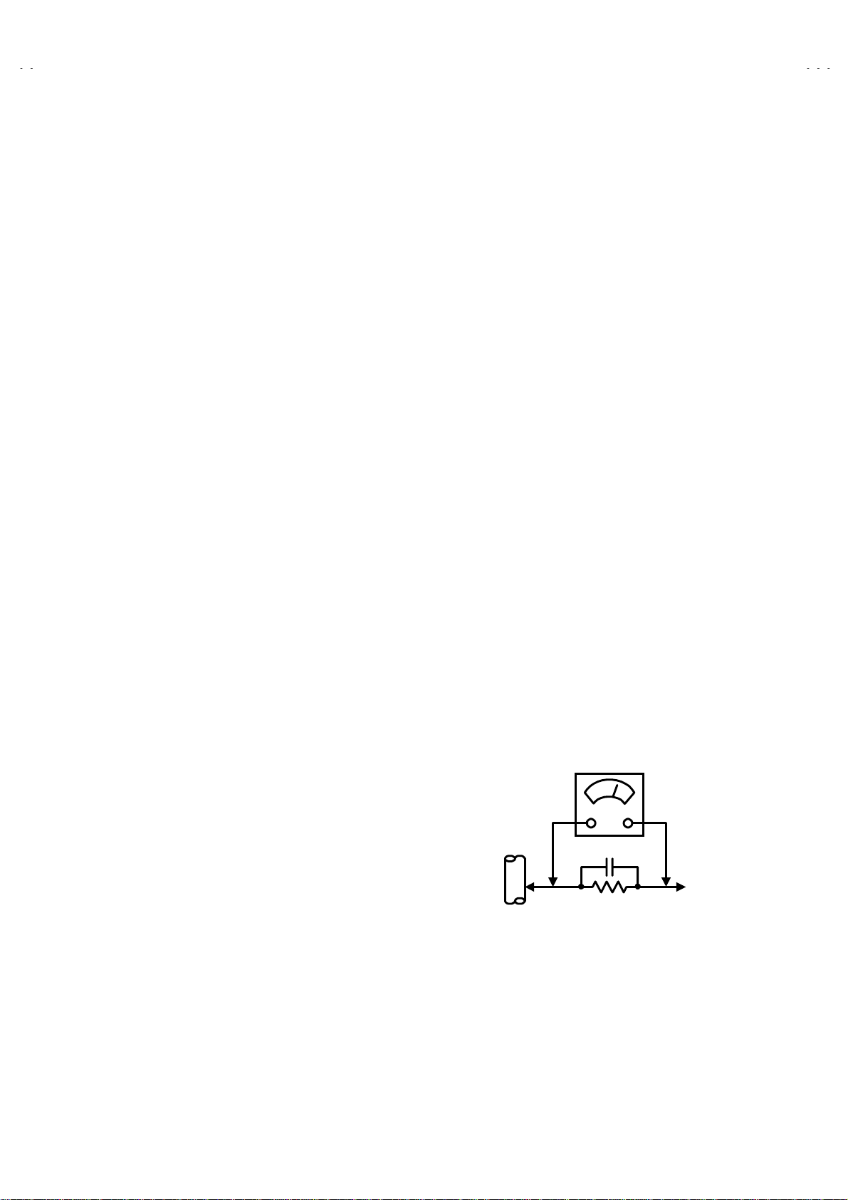
Alternate Check Method
""""
Plug the AC lin e c or d dir ec t l y int o t he AC outl et (d o not use a line
isolati on transform er during t his check. ). Use an AC voltmet er
having 1000 ohms per volt or more sensitivity in the following
manner. Connect a 1 500! 10W resistor paralleled by a 0.15"F
AC-typ e capacitor betw een an expos ed metal part and a know n
good earth ground (water pipe, etc.). Measure the AC voltage
across the resistor with the AC voltmeter. Move the resistor
connect ion t o each exp os ed met al p art, part icul arl y any exp osed
metal part h avin g a return p ath to th e chassis , and meas ure th e
AC voltag e across the res istor. N ow, re vers e the plug in the AC
outlet and repeat each measurement. Any voltage measured
must not exceed 0.75V AC (r.m.s.). This corresponds to 0.5mA
AC (r.m.s.).
However , i n t ropic al ar ea, t his m us t n ot exceed 0. 3 V A C (r.m.s . ).
This corresponds to 0.2mA AC (r.m.s.).
AC VOLTMETER
0.15μF AC-TYPE
1500
GOOD EARTH GROUND
!
(HAVING 1000
OR MORE SENSITIVITY)
10W
/V,
!
PLACE THIS PROBE
ON EACH EXPOSED
METAL PART
No.51892
3
Page 4
A
V-21LTG1
FEATURES
New chassis design en ables use of an interact i ve on-s c reen c ontrol.
"
Wide range voltage (110V~240V) AC p ow er input.
"
With AUDIO / VIDEO INPUT & OUTPUT terminal.
"
MUTING button can reduce the audio level to zero instantly.
"
Functional remote control to operate TV set (for channel select, volume control, power ON/OFF, etc.) from a distance.
"
2
C bus control utilizes single chip ICs for IF, V/C, DEF. VSM PRESET, PRESET & TURBO TIMER.
I
"
By means of AUTO PROGRAM, the TV stations can be selected automatically and the TV channels can also be rearranged automatically.
"
Built-in ECO MODE (ECONOMY, ECOLOGY)
"
In accord ance with th e brightn ess i n a room, the br ightness and / of contr ast of the pic ture can be adjusted au tomaticall y to make t he
optimu m pic tu re which is easy on the eye.
Built-in ON TIMER, RETURN + & CHILD LOCK.
"
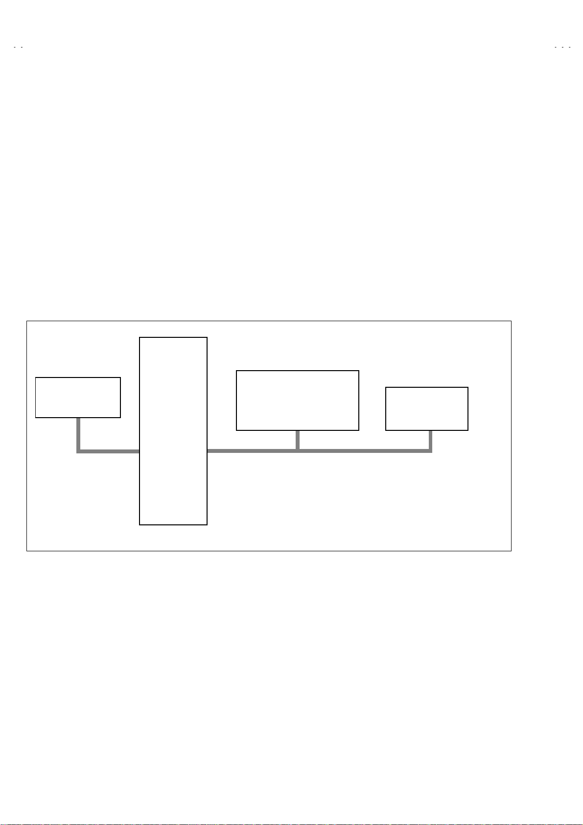
SYSTEM BLOCK DIAGRAM
IC702
MEMORY
SCL2/SDA2
IC701
MICRO
COMPUTER
IC301
VIDEO/CHROMA
DECORDER
SCL1/SDA1
TU001
TUNER
4
No. 51892
Page 5
A
FUNCTIONS
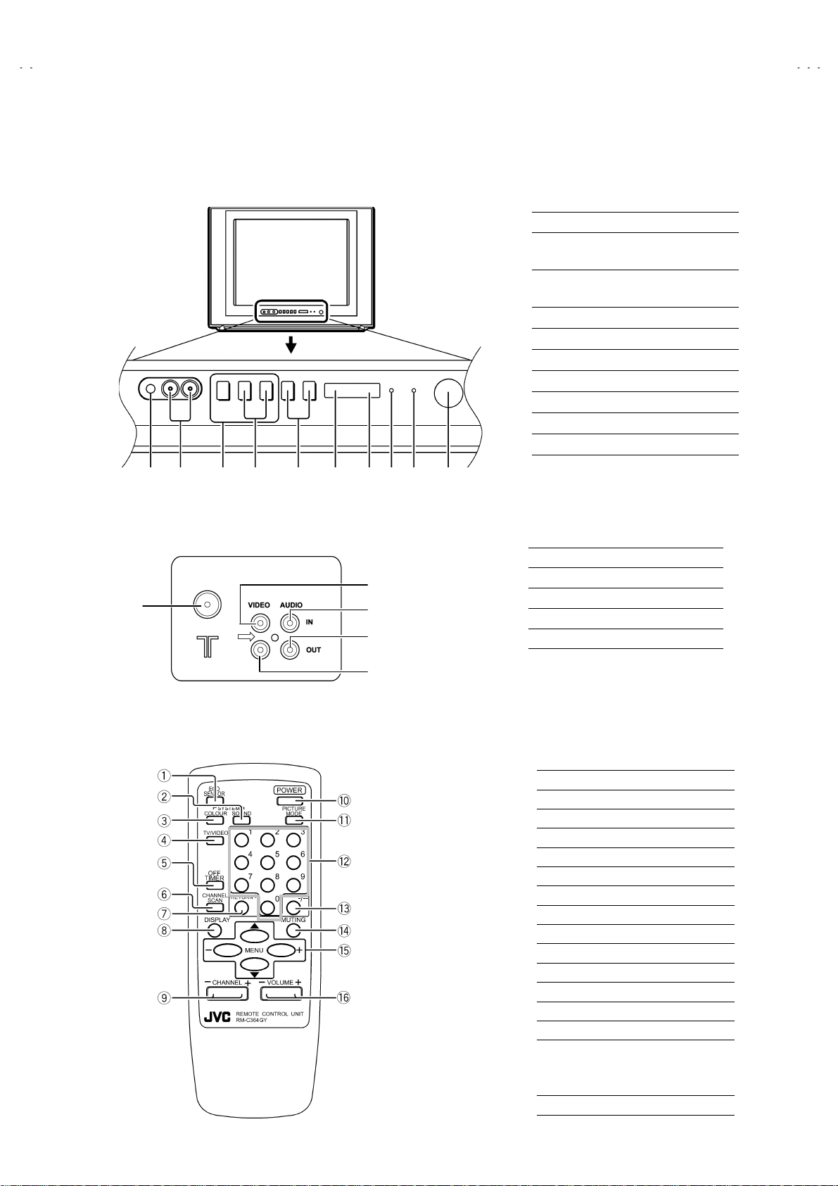
FRONT PANEL
■
MENU buttons
①
CHANNEL -/+ buttons
②
(MENU -/+ buttons)
VOLUME -/+ buttons
③
(MENU -/+ buttons)
ECO sensor
④
REMOTE CONTROL sensor
⑤
ON TIMER lamp
⑥
POWER lamp
⑦
MAIN POWER button
⑧
A/V INPUT terminal
⑨
HEADPHONE jack
⑩
V-21LTG1
⑩⑨ ①
REAR TERMINAL
■
②
③
④
⑤⑥
②
①
④
⑤
③
REMOTE CONTROL UNIT(RM-C364GY)
■
⑦
⑧
ANT Terminal
①
VIDEO INPUT Terminal
②
VIDEO OUTPUT Terminal
③
AUDIO INPUT Terminal
④
AUDIO OU T PUT Terminal
⑤
ECO SENSOR key
①
SOUND SYSTEM key
②
COLOUR SYSTEM key
③
TV/VIDEO key
④
OFF TIMER key
⑤
CHANNEL SCAN key
⑥
RETURN+key
⑦
DISPLAY key
⑧
CHANNEL -/+ key
⑨
POWER key
⑩
PICTURE MODE key
⑪
NUMBERS (CH.) key
⑫
⑬ -/--
MUTING key
⑭
MENU key
⑮
MENU ▲/▼ key
MENU -/+ key
VOLUME -/+ key
⑯
key
No. 51892
5
Page 6

A
V-21LTG1
SPECIFIC SERVICE INSTRUCTIONS
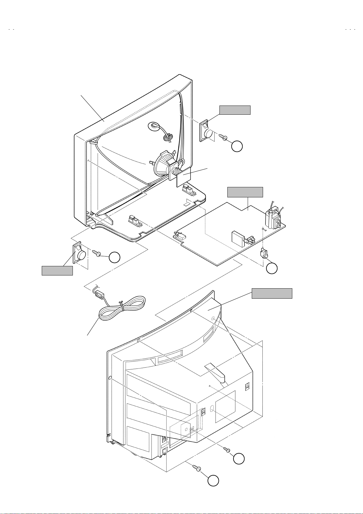
DISASSEMBLY PROCEDURE
REMOVING THE REAR COVER
1. Unplug the power plug.
2. As shown in fig ure, remove t he
screw mar k ed
3. Withdraw the rear cover toward you.
""""
.
screws marked
7
REMOVING THE PW BOARD
After removi ng the rear cover.
"
1. Slightly raise the bot h sides of t he PW BO ARD by hand and
remove the PWB stopper marked
from the FRONT CABINET.
2. Withdraw the PW BOARD backward.
(If necessary, t ak e of f the wir e clamp and c onnectors , etc . )
under th e PW BOARD
####
REMOVING THE SPEAKER
After rem ovi ng the rear cover.
"
1. As shown in figure, remove the
2. Follow the same steps when removing the other hand speaker.
screws marke d
2
$$$$
!!!!
.
and a
CHECKING THE PW BOARD
1. To check the back side of the PW Board.
1) Pull out the PW Board. (Refer to REMOVING THE PW Board)
2) Erect the PW B oar d ver t ically so that you can eas il y check the
back side of the PW Board.
[CAUTION]
When erecting the PW Board, be careful so that there will be no
"
co n tac ting wit h oth e r P W Board.
Before turning on power, make sure that the CRT earth wire and
"
other conn ec tor are pr op erl y c onnected.
WIRE CLAMPING AND CABLE TYING
1. Be sure to clamp the wire.
2. Never remove the cable tie used for tying the wires together.
Should it be inadvertently removed, be sure to tie the wires with a
new cable tie.
6
No. 51892
Page 7
A
FRONT CABINET
V-21LTG1
SPEAKER
D
CRT SOCKET PWB
PW BOARDB
SPEAKER
POWER CORD
D
C
PWB STOPPER
REAR COVER
B
A
No. 51892
7
Page 8
A
V-21LTG1
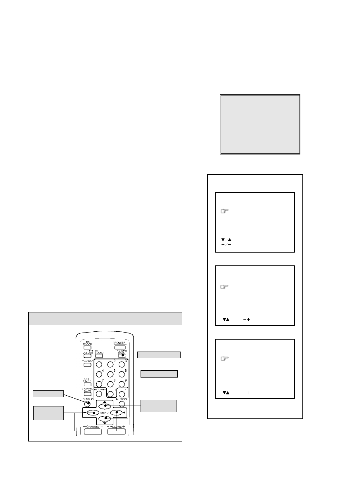
REPLACEMENT OF MEMORY ICs
1. MEMORY ICs
This mod el uses memory ICs. This m em ory IC data ar e f or pr op er oper ation of th e vid eo and defl ec ti on circuits.
When replaci n g m emor y ICs , be sure to use ICs writt en with the initi al v alu es of d ata.
2. PROCEDURE FOR REPLACING MEMORY ICs
(1) Power off
Switch th e p ow er off and disc onnect th e power pl ug from the wall outlet.
(2) Replace ICs
Be sure to u se memory ICs written with the initial data values.
(3) Power on
Connect the power plu g into the wall outlet an d s wit c h th e pow er on.
(4) Check and set SYSTEM CONSTANT SET
It must not adjust without adjustment signals.
1) Press the
DISPLAY
CONTROL UNIT simultaneously.
2) T he SER V I CE MEN U scr een of Fig . 1 will be display ed.
3) W hile the S ERVI CE MEN U is dis pl ayed, again press th e
PICTURE MODE
screen of Fi g. 2 will be displa yed.
4) C h eck t h e s et ti ng valu es of th e SYST EM C O NSTAN T S ET of T abl e 1 If th e
value is dif ferent, s elect the s etting it em with the
the correct value with the
5) Press the
DISPLAY
(5) R ec eive chann el o f set t in g
Refer to the
OPERATING INSTRUCTIONS
(channels preset) as described
(6) User Setting
Check th e us er s ettin g valu e of T able 2, an d if setti ng val ue is diff erent , s et th e
correct val u e.
For setting, refer to the
(7) Setting of SERVICE MENU
Verif y the s etting items of th e SE R VIC E MENU of , and reset where nec essary.
For setting, refer to the
.
KEY ASSIGNMENT OF REMOTE CONTROL UNIT
key and the
PICTURE MODE
key of the REMOTE
DISPLAY
key s imultaneous ly, and th e SYSTEM CONSTAN T SET
▼/▲key, and set
MENU
-/+ key.
MENU
key twice, and return to the normal screen.
and set the receive channels
OPERATING INSTRUCTIONS
SERVICE ADJUSTMENTS
.
.
key an d
SERVICE MENU
1.IF 2.V/C
3.DEF 4.VSM PRESET
5.PRESET
6.TURBO TIMER OFF
1-6 SELECT DISP : EXIT
******
***********
***** **
************
**********
*** ** **
*** ** **** ***
*** ** ***** ** **
**.***
****
** ***
** ***** ***
Fig.1
SYSTEM CONSTANT-
SYSTEM CONSTANT SET 1
COLOUR : TRIPLE
BILINGUAL : NO
TUNER : MU
ECO SENSOR : YES
LANGUAGE : E/A/F/R
: SELECT
: OPERATE DISP : EXIT
SYSTEM CONSTANT-
SYSTEM CONSTANT SET 2
B/B SOUND : OF F
LOCK : 180
COLOUR AUTO : NO
QSS : MINT
ALC : NO
TEXT RATE : 20
:SEL
:OPE DISP:EXIT
***
******
ⅠⅠⅠⅠ
ⅡⅡⅡⅡ
SYSTEM CONSTANT-
PICTURE MODE key
CHANNEL key
DISPLAY ke y
MENU
key
MENU
key
-/+
8
▼/▲
No. 51892
SYSTEM CONSTANT SET 3
AMP TUNER : NO
VNR : YES
EW-PIN IC : NO
:SEL
:OPE DISP:EXIT
Fig.2
ⅢⅢⅢⅢ
Page 9
A
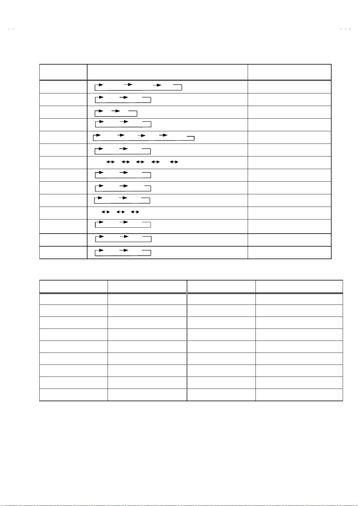
SETTING OF SYSTEM CONSTANT SET
Setting item Setting contents Setting value
V-21LTG1
COLOUR
BILINGUAL
TUNER
ECO SENSOR
LANGUAGE
B/B SOUND
LOCK
COLOUR AUTO
QSS
ALC
TEXT RATE
AMP TUNER
VNR
EW-PINIC
MULTI.
YES
MU
YES NO
E/A/F
ON OFF
YES 10 20
YES
MINT
YES NO
10 20 40 80
YES
YES
YES
NO
MA
NO
MQSS
NO
NO
NO
PALTRIPLE
E/F
230 240
~
E/R/A/FE/A
TRIPLE
NO
MU
YES
E/A/F/R
OFF
180
NO
MINT
NO
20
NO
YES
NO
Table 1
USER SETTING VALUES
Setting item Setting value Setting item Setting value
MAIN POWER OFF PICTURE MODE (VSM) BRIGHT
SUB POWER ON LANGUAGE ENGLISH
CHANNEL POSITION 1 POSITION CHANNEL PRESET Refer to OPERATING INSTRUCTION
VOLUME About 10 ECO SENSOR OFF
TV/VIDEO TV VNR OFF
ON SCREEN DISPLAY POSITION INDICATION AUTO SHUTOFF OFF
COLOUR SYSTEM PAL ON TIMER PR1 0:00
SOUND SYSTEM B / G BLUE BACK OFF
OFF TIMER OFF (shown : 00 ) CHILD LOCK OFF
Table 2
No. 51892
9
Page 10
A
V-21LTG1
INITIAL SETTING VALUE OF SERVICE MENU
1. Adjustment of the SERVICE MENU is made on the basis of the initial setting values ; however, the new setting values which
set the screen in its optimum condition may differ from the initial setting.
2. Do not change the initial Setting Values of the Setting (Adjustment) items not listed In “ADJUSTMENT”.
2. V/C
Setting item
2. DRIVE
3. BRIGHT
4. CONT.
5. COLOUR
6. TINT
7. SECAM BL ADJ.
8. SHARP
(Do Not Adj.)
3. DEFLECTION
Setting item Variable range
1. VER. POSITI ON
2. HOR. POSITION
Colour system
RED
GREEN1. CUT OFF
BLUE
RED
BLUE
TV
VIDEO
TV
VIDEO
Variable
range
-128~+127
-128~+127
-127~+127
-63~+63
-63~+63
-63~+63
-31~+31
-32~+31
-04 ~ +03 - 1 - 3
-16 ~ +15 +3 + 3
PAL SECAM NTSC 3.58 NTSC 4.43
-50
+ 0
+ 0
+ 0
+ 0
+ 0
- 5(Fixed)
+15(Fixed)
fv : 50Hz MODE fv : 60Hz MODE
Initial settin g val ue
+ 0 + 0
+ 8 + 0
Initial settin g val ue
3. VER. HEIGHT
4. VER. LINEARITY
5. VER. SCURVE
6. HOR. VCO ADJUST
4. VSM PRESET
VSM preset
VSM mode
Setting item
SETTING VALUE +15
TINT
COLOUR
BRIGHT
CONT.
SHARP
SETTING VALUE
SETTING VALUE
SETTING VALUE
SETTING VALUE
-64 ~ +63 -35 + 1
-32 ~ +31 +15 - 1
-32 ~ +31 -32 + 0
-63 ~ +62 + 0 + 0
BRIGHT STANDARD SOFT
+15
+15
+30 +15 +11
+15 +12
10
No. 51892
Page 11

A
5. PRESET
The items in the following table, it is no requirement for adjustment.
If values had changed by the miss operation, set the initial setting values in the following table.
Colour System (Do Not Adj u st )
Setting item
1. C TRAP FIX
2. SHARP PEAK
PAL SEC AM NTSC 3.58 NTSC 4.43
111 1
000 0
Initial setting value (Fixed value)
V-21LTG1
3. ABL
4. GAMMA
5. Y. DELAY TIME
6. BLACK EXP START
7. C-BPF
8. CW / SCP
9. VIF DET LEVEL
11. IF AGC MIN
12. VIF AGC
13. VIF PMOD
19. VNR
20. RGB LIM
21. RGB LIMIT LEVEL
23. TEXT H. POSITION
TV
VIDEO
TV
VIDEO
111 1
000 0
022 3
020 2
333 3
110 0
111 1
0
+
000 0
000 0
000 0
000 0
15 15 15 15
111 1
222 2
-3 -3 -3 -3
0
+
0
+
0
+
24. READ DATA
Sound System (Do Not Adjust)
Setting item B/G I D/K M
10. SIF DET LEVEL
14. SIF BPF BW ADJUST
15. SIF TRA P FO ADJUST
16. SIF TRA P FO ADJUST 2
17. SIF -TRAP
18. SIF -BPF
22. SIF SW
0
+
0
+
0
+
0
+
000 0
000 1
111 0
No. 51892
0
+
0
+
0
+
0
+
0
+
0
+
0
+
0
+
0
+
0
+
0
+
0
+
11
Page 12

A
V-21LTG1
REPLACEMENT OF IC301 (IF V/C DECODER)
For the IC3 01(IF V/C DEC ODER) of this model , all data ar e written in t he micro-c omputer . So, write t he data in the micro-
"
comput er i n ac cor d ance with the follo wi ng pr oc edures b efore start in g adj u stment.
RE PLACING PR OCE D URES
Turn the POWER OFF.
(1)
Replace the IC301 with a new one.
(2)
While pr essi ng MENU but t on and VO L+ bu tt on O N t he FR ONT CAB INET s imu lt aneous l y, tur n the POWER ON. When th e POW ER is
(3)
turned ON, the data is written in the micro-computer immediately.
LOCATIONS OF FRONT PANEL BUTTONS AND LAMPS
MENU buttons
①
①② ③ ④⑤⑥⑦ ⑧
CHANNEL
②
(MENU
VOLUME
③
(MENU
ECO sensor
④
REMOTE CONTROL sensor
⑤
ON TIMER lamp
⑥
POWER lamp
⑦
MAIN POWER button
⑧
----/++++
----/++++
----/++++
buttons)
----/++++
buttons)
buttons
buttons
12
No. 51892
Page 13

A
SERVICE ADJUSTMENT
BEFORE STARTING SERVICE ADJUSTMENT
1. There are 2 way of adjusting this TV: One is with the
REMOTE CONTRO L UNIT and t he oth er is t he conv ention al
method using adjustm ent pa rts and components.
2. T he adju stment with t he REM OTE C ONTR OL UNIT is m ade
on the basis of the initial setting values. The setting values
which adjust the scree n to its o ptimum c on d ition may di ff er
from the initial setting values.
3. Make sure that connection is correctly made to AC power
source.
4. T urn on the power of th e set and equipment bef ore use, and
start the adjustment procedures after waiting at least 30 minutes.
5. Unl ess other wis e specifi ed, prep are the mos t suitab le rec eption
or input signal for adjustment.
6.
Never touch a ny adjustment par ts, which are not specified
in the list for thi s a djust men t VR s, tr an sfor ms, cond en ser s,
etc.
7. Preparation for adjustment
Unless oth erwis e sp ec ified in t h e adj us t m en t i ns tr uc t ions, preset
the following functions with the REMOTE CONTROL UNIT.
User menu pres et value
PICTURE MODE (VSM) BRIGHT
VNR OFF
TINT / COLOUR / BRIGHT /
SHARP / CONT.
BLUE BACK OFF
OFF TIMER OFF
ECO SENSOR OFF
AUTO SHUT OFF OFF
V-21LTG1
MENU ITEM PRESET VALUE
CENTER
MEASURING INSTRUMENT AND FIXTURES
1. DC voltmeter (o r digital voltm eter)
2. Oscilloscope
3. Signal generator (Pat tern generator) [PAL / SECAM / NTSC]
4. Remote control unit
ADJUSTMENT ITEMS
Adjustment item
B1 POWER SUPPLY
FOCUS adj us tment
IF circuit adjustment
V/C (Video / Chroma) circuit adjustment
DEFLECTION circuit adjustment
VSM PRESET setting
PURITY, CONVERGENCE adjustment
No. 51892
13
Page 14

A
V-21LTG1
BASIC OPERATION OF SERVICE MENU
The adjustment using SERVICE MENU
"
The followi ng adjustm ent items us e the SERVICE ME NU in the seri es of the adjust ment. The adjus tments are made on the basis of the
initial setting values. The adjustment values which adjust the screen to the optimum condition can be different from the initial setting values.
With the SERVICE MENU, various settings can be made, and they are broadly classified in the following items of settings.
1.IF
・・・・・・・・・・・・・・・・・・・・・・・
2.V/C
・・・・・・・・・・・・・・・・・・・・・・
3.DEF
・・・・・・・・・・・・・・・・・・・・・
4.VSM PRESET
5.PRESET
6.TURBO TIMER
Key operation of the SERVICE MENU
"
・・・・・・・・・・・・
・・・・・・・・・・・・・・・・・
・・・・・・・・・・・・
[Enter to SERVICE MENU]
Press the
DISPLAY
key and th e
UNIT simultaneously. Then enter the SERVICE MENU mode as shown in Fig.1.
Adjustment of the IF circuits.
Adjustment of the VIDEO/CHROMA circuit.
Adjustment of the DEFLECTION circuit.
Adjustm en t of th e initial s ettin g val ues of VSM c on d it i on as STANDAR D , SO FT and BRIGH T.
(VSM : Video Status Memory)
Adjustmen t of the RF circuit
[Do not adjust]
.
For quick s et ti ng t h e TI MER c ou nt value, ad jus t able not onl y b y mi nuets but also by second.
[Should be OFF]
PICTURE M ODE
.
key of the REMOTE CONTROL
[Exit from SERVICE MENU]
When complete the adjustment work, press the
DISPLAY
key to return to the
SERVICE MENU.
And then press the
DISPLAY
key again, return to the normal screen.
[Select from SERVICE MENU]
In SERVICE MENU , press the number (1~6) key of the remote control unit, to select
any of the adj ustmen t it ems .
The colours which selected item characters are changed.
KEY ASSIGNMENT OF REMOTE CONTROL UNIT
SERVICE MENU
SERVICE MENU
1.IF 2.V/C
3.DEF 4.VSM PRESET
5.PRESET
6.TURBO TIMER OFF
1-6 SELECT DISP : EXIT
******
***********
***** **
************
**********
*** ** **
*** ** **** ***
*** ** ***** ** **
**.***
****
** ***
** ***** ***
***
******
Fig.1
PICTURE
MODE key
CHANNEL
key
MENU
▼/▲
key
14
DISPLAY ke y
No. 51892
MENU
-/+
key
Page 15

A
[Method of setting]
1. IF
[1. VCO]
1 key
①
②
③
④
[2. DELAY POINT]
①
②
③
④
・・・・・・・・・・・・・・・・・・・・・・・・・
1 key
・・・・・・・・・・・・・・・・・・・・・・・・・
The VCO (CW) screen w il l be dis played a allow mark wh en the AF C vol t age is at a certai n l evel.
DISPLAY key
1 key
・・・・・・・・・・・・・・・・・・・・・・・・・
2 key
・・・・・・・・・・・・・・・・・・・・・・・・・
MENU -/+ key
DISPLAY key
・・・・・・・・・・・・・・・・・・
・・・・・・・・・・・・・・・・
・・・・・・・・・・・・・・・・・・
Selec t
Selec t
As you press this key twice, you will return to the
Selec t
Selec t
Set (adjust) the setting values of the setting items.
When this is pre ssed twice, you will return to the
.
1.IF
1.VCO
.
1.IF
2.DELAY POINT
.
SERV ICE MEN U
SERVICE MENU
V-21LTG1
.
.
2.V/C, 3.DEF
2~4 key
①
MENU ▼/▲ key
②
MENU -/+ key
③
DISPLAY key
④
6.TURBO TIMER
By pressing the 6 key, you can change the ON or OFF (
①
and
4.VSM PRESET
・・・・・・・・・・・・・・・・・・・・・・・
・・・・・・・・・・・・・・・
・・・・・・・・・・・・・・・・
・・・・・・・・・・・・・・・・・・
Select on e from
Select setting items.
Adjust the values of the items.
When this is pressed , return to the
If it is ON, the timer in TIMER mode changes from 1 minute into 1 sec temporarily.
(It is easier to checks the Operation of TIMER)
If you turn the TV power off, this setting becomes OFF automatically.
2. V/C, 3. DEF
should be O FF
and
4. VSM PRESET
SERV ICE MEN U
).
.
.
No. 51892
15
Page 16

A
V-21LTG1
SERVICE MENU FLOW CHART
SERVICE MENU
SERVICE MENU
1.IF 2.V/C
3.DEF 4.VSM PRESET
5.PRESET
6.TURBO TIMER OFF
1-6 SELECT DISP : EXIT
******
***********
***** **
************
**********
*** ** **
*** ** **** ***
*** ** ***** ** **
6.TURBO TIMER
** ***
** ***** ***
OFF
ON /
**.***
***
****
******
OFF
(By pressing 6-key)
SUB MENU 1. IF
IF
1. VCO
2. DELAY POINT
1-2 : SELECT DISP : EXIT
SUB MENU 2. V/C
V/C PAL
1. CUTOFF
50Hz
/ :SELECT
- / + : OPERATE DISP : EXIT
(R)
(G)
(B)
* **
* **
* **
VCO (CW)
TOO HIGH
ABOVE REFERENCE
JUST REFERENCE
BELOW REFE RENCE
TOO LOW
AFT ADJUST
VCO ADJUST
FINE
DELAY POINT UHF
AGC TAKE-OVE R
- / + : OPERATE DISP : EXIT
***.**
MHz
***(**)
***(**)
***(**)***(**)
***(**)
***(**)
***(**)***(**)
DISP : EXIT
**
SUB MENU 3. DEF
DEF
1. VER. POSITION
50Hz
/ :SELECT
- / + : OPERATE DISP : EXIT
PAL
***
SUB MENU 4. VSM PRESET
BRIGHT
TINT
COLOUR
BRIGHT
CONT.
SHARP
/ :SELECT
- / + : OPERATE DISP : EXIT
**
**
**
**
**
SUB MENU 5. PRESET
PRESET
1. C-TRAP FIX
50Hz
/ :SELECT
- / + : OPERATE DISP : EXIT
16
PAL
No. 51892
B/G
***
Page 17

A
ADJUSTMENT LOCATIONS
TOP
CRT SOCKET PWB
TP-47R/G
V-21LTG1
(SOLDER SIDE)
U
FRONT
PW
TP-47G/R
MAIN PWB
F901
TP-47B
TP-E
E1
T
IC701
IC702
MEMORY IC
CRT EARTH WIRE
(BRAIDED ASS'Y)
DEG
S
TU001
IC301
T
No. 51892
1Pin TP-91(B1)
2Pin NC
3Pin X-ray1
4Pin X-ray2
5Pin TP-E( )
1
S
HV
U
HVT
UPPER:FOCUS
LOWER:SCREEN
17
Page 18

A
V-21LTG1
ADJUSTMENTS
B1 POWER SUPPLY
Item
Check of
B1 Power
Measuring
instrument
Signal
generator
Supply
DC Vol t meter
FOCUS ADJUSTMENT
Item
Adjustment
of FOCUS
Measuring
instrument
Signal
generator
IF CIRCUIT ADJUSTMENT
Item
Measuring
instrument
Test point Adjustment part Description
TP-91 (B1)
TP-E (
####
)
1. Inp ut a w h ol e blac k sig n al.
2. Connect a DC voltmeter to TP-91(B1) and TP-E (#).
3. Make sure that the voltage is DC114.5±1.5V.
Test point Adjustment part Description
FOCUS VR
[In HVT]
1. Input a cross-hatch signal.
2. While watc hing t he scr een, ad just t he FOCU S VR t o mak e the
vertic al and hor i z ontal lines as fi n e and s h arp as poss i ble.
3. Make sure that when the screen is darkened, the lines remain in
good focus.
Test point Adjustment part Description
Adjustment
of VCO(CW)
Signal
generator
Remote
control unit
VCO (CW)
TOO HIGH
ABOVE REFERENCE
JUST REFERENCE
BELOW REFE RENCE
TOO LOW
AFT ADJUST
VCO ADJUST
FINE
DISP : EXIT
ADJUSTMENT AT THIS POINT IS USELESS
***.**
MHz
***(**)
***(**)
***(**)***(**)
***(**)
***(**)
***(**)***(**)
ADJUSTMENT POINT
1. VCO
YELLOW
Do not adjust
TOO HIGH
ABOVE REFERENCE
JUST REFERENCE
BELOW REFERENCE
TOO LOW
Please use signal generator which is correct proof about the
●
sending frequency.
1. Input the PAL full colour bar (210.25MHz) signal.
2. Select 1.IF from the
3. Pr ess 1 key and select
4. Select
5. Press
VCO ADJUST
MENU
SERV ICE MEN U
1.VCO
with
MENU
-/+ key until the colour of the characters TOO
HIGH ch anges blu e to yel low. Th en gr ad uall y pr ess t he
.
.
▲/▼ key.
MENU
-/+ key until the TOO LOW changes yellow. At this time, confirm
th a t the v a lu e of
6. Select
7. Press
AFT A D JUST
MENU
VCO ADJUST
with
-/+ key until the char acters JUST REFERENCE
MENU
is near +00.
▲/▼ key.
changes blue to yellow.
8. Press the
DISPLAY
key three times to return to normal scree n .
18
No. 51892
Page 19

A
V-21LTG1
Item
Adjustment
of DELAY
POINT
(AGC)
Measuring
instrument
Signal
generator
Remote
control unit
Test point Adjustment part Description
DELAY POINT
(AGC TAKE-OVER)
1. Inp ut a bl ac k an d w hit e si gnal (c olour of f ) .
2. Select
3. Select
from the SERVICE MENU.
1. IF
2. DELAY POINT
control un it.
4. Set the s etti ng v alues wi th of the set ti ng items as s h ow n b ellow
table.
5. Adjust th e MEN U - or + key u nt il vi d eo noise dis appears.
6. Turn to other channels and make sure that there are no
irregularities.
DELAY POINT UHF
AGC TAKE-OVER
- / + : OPERATE DISP : E XIT
**
by pres sing t he 2 key on the remote
Setting Item Variable range Initial setting value
DELAY POINT
(AGC TAKE OVER)
NTSC 3 . 58
OTHER
0~127
48
43
No. 51892
19
Page 20

A
V-21LTG1
VIDEO / CHROMA CIRCUIT ADJUSTMENT
The setting (adjustment) using the REMOTE CONTROL UNIT is made on the basis of the initial setting values.
The setting values which adjust the screen to the optimum condition can be different from the initial setting values.
Do not change the initial setting values of the setting items not listed in “ADJUSTMENT”.
Item
Adjustment
of WHITE
BALANCE
(Low light)
Measuring
instrument
Signal
generator
Remote
control unit
Test point Adjustment part Description
V/C PAL
1. CUTOFF
50Hz
/ :SELECT
- / + : OPERATE DISP : EXIT
KEY ASSIGNMENT OF REMOTE CONTROL UNIT
CUTOFF OFF
(H.LINE OFF)
CUTOFF ON
(H.LINE ON)
R. CUTOFF( )
R. CUTOFF( )
▲
R. DRIVE( )
▲
▼
R. DRIVE( )
▼
123
4
7
R
56
8
9
GB
1. CUT OFF (R)
CUT OFF (G)
CUT OFF (B)
SCREEN VR
[IN HVT]
(R)
* **
(G)
* **
(B)
* **
G.CUTOFF( )
B. CUTOFF( )
B. DRIVE( )
B. CUTOFF( )
B. DRIVE( )
G.CUTOFF( )
1. Inp ut a bl ac k an d w hit e si gnal (c olour of f ) .
2. Select
(R), (G) and (B) .
OFF
from the SERVICE MENU, then select
2. V/C
1. CUT
3. Set each value to initial setting value with 4~9 keys of the
remote control unit.
4. Press t he
key of the rem ote contr ol unit to show the singl e
1
horizontal line on screen.
5. Turn the
SCREEN VR
fully coun te r- clockwi se , the n s lo wly tu r n i t
clockwis e to where one of a red, blu e or green colour is f aintly
visible.
6. Use keys
of the remote contr ol u nit an d ad jus t the oth er 2
4~9
colours which except t he appeared c olour to wh ere the singl e
horizontal line appears white.
7. Turn the
SCREEN VR
to where the single horizontal line glows
faintly.
8. Press the
9. Press the
▲
▲
▲
▲
▲
▲
1. CUT OFF
key to turn off th e si ngl e h or iz on tal line.
2
DISPLAY
Adjustment item
key twice to return to the normal screen.
Variable
range
-128~+127
R
-128~+127
G
-128~+127
B
Initial settin g
value
-50
-50
-50
Adjustment
of WHITE
BALANCE
(High light)
Signal
generator
Remote
control unit
2. DRIVE (R
DRIVE (B)
)
1. Input a black an d w hit e signal (colour off).
2. Select
3. Select
from the SERVICE MENU.
2. V/C
2. DRIVE (R) / (B)
with M ENU ▼/▲ key, and set each
value to ini tial s et ting valu e wit h 4 and 7 or 6 and 9 k eys of the
remote control unit.
4. Use the keys
and 7 or 6 and 9 to produc e a wh it e sc reen
4
5. Press the D ISPLAY key twice to return to the nomal screen.
V/C PAL
2. DRIVE
50Hz
/ :SELECT
- / + : OPERATE DISP : EXIT
20
(R)
(B)
* **
* **
No. 51892
Adjustment item
2. DRIVE
R
B
Variable
range
-128~+127
-128~+127
Initial settin g
value
+0
+0
Page 21

A
V-21LTG1
Item
Adjustment
of
SUB
BRIGHT
Adjustment
of
SUB CONT.
Adjustment
of
SUB
COLOUR
ⅠⅠⅠⅠ
Measuring
instrument
Remote
control unit
Remote
control unit
Remote
control unit
Test point Adjustment part Description
3. BRIGHT
4. CONT.
5. COLOUR [Method of adjustment without measuring instrument]
PAL COLOUR
1. Receive an y br oad cast.
2. Select
3. Select
4. Set the initial setting value with the MENU -or+ key.
5. If the brigh tness is n ot the best w ith the initi al set valu e, mak e
fine adjus t m ent un til you get the bes t brightn ess .
1. Receive an y br oad cast.
2. Select
3. Select
4. Set the initial setting value with the MENU -or+ key.
5. If the contrast is not the best with the initial set value, make fine
adjust m ent un t il you get t h e bes t c ontrast.
1. Receive a PAL broadcast.
2. Select
3. Select
4. Set the initial setting value for PAL COLOUR with the MENU
-or+ key.
5. If the colour is not the best with the initial set valu e, make fine
adjust m ent un t il you get t h e bes t c ol our .
from SERVICE MENU.
2. V/C
3. BR I GHT
2. V/C
4. CONT
2. V/C
5. COLOUR
with the MENU ▼/▲key.
from SERVICE MENU.
. with the MENU ▼/▲key.
from the SERVICE MENU.
with the MENU ▼/▲ key.
SECAM COLOUR
NTSC 3.58 COLOUR
NTSC 4.43 COLOUR
No. 51892
1. Receive a SEC A M broadcas t .
2. M ak e fine adjust m en t of S EC AM COLOUR as previ ous l y.
1. Receive a NT S C 3.58 MHz broadcast.
2. Make similar fine adjustment of NTSC 3.58 COLOUR as
previously.
When NTSC 3.58 adjustment completed, NTSC 4.43 will be
automatically set at the respective values.
21
Page 22

A
V-21LTG1
Item
Adjustment
of SUB
COLOUR
ⅡⅡⅡⅡ
W
Measuring
instrument
Signal
generator
Oscilloscope
Remote
control unit
Y
Cy
Test point Adjustment part Description
TP-47G/R
TP-E (
####
[CRT SOCKET
PWB]
Mg
5. COLOUR [Method of adjustment using measuring instrument]
)
R
(A)
PAL COLOUR
B
(-)
0V
(+)
1. Input a PAL full field colour bar signal (75% white).
2. Select
3. Select
4. Set the initi al s ett i ng val ue of PAL COLOU R with the ME NU
- or + key.
5. Connect the oscilloscope between TP-47G/R and TP-E (#).
6. Adjust PAL C OLOUR t o bring the val u e of
to +9V(W-G). (Voltage value b etween (W) and (G))
from SERVICE MENU.
2. V/C
5. COLOUR
with the MENU ▼/▲ key.
G
SECAM COLOUR
1. Input a SECAM full field colour bar signal (75% white).
2. S et the initi al s etti ng val u e of SECAM CO LOUR with the MENU
- or + key.
3. Adjust SECAM COLOUR to bring the value of
illustr ation to +6V(W-G ). (V oltage value between (W) and (G))
in the illustration
(A)
(A)
in the
NTSC 3.58 COLOUR
NTSC 4.43 COLOUR
22
1. Input a NTSC 3.58 full field colour bar signal (75% white).
2. Set the initial setting value of NTSC 3.58 COLOUR with the
MENU - or + key.
3. Adjust NTSC 3 .58 COLOUR to bring the value of
illustr ation to +8V(W-G ). (V oltage value between (W) and (G))
When NTSC 3.58 is set, NTSC 4.43 will be automatically set at the
respective val u es .
No. 51892
(A)
in the
Page 23

A
V-21LTG1
Item
Adjustment
of TINT
ⅠⅠⅠⅠ
Adjustment
of TINT
ⅡⅡⅡⅡ
Measuring
instrument
Signal
generator
Remote
control unit
Signal
generator
Oscilloscope
Remote
control unit
Test point Adjustment part Description
6. TINT [Method of adjustment without measuring instrument]
1. Input a NTSC 3.58 full field colour bar signal (75% white).
2. Select
3. Select
4. S et the init ial s ett ing valu e of NT SC 3.58 with th e MENU - or +
key.
5. If you cannot g et the b est tint wi t h th e init i al s ett in g val u e, m ak e
fine adjustment until you get the best tint.
When NTSC 3.58 is set, NTSC 4.43 will be automatically set at the
respective val u es .
1. Input a NTSC 3.58 full field colour bar signal (75% white).
2. Select
3. Select
4. S et the init ial s ett ing valu e of NT SC 3.58 with th e MENU - or +
key.
5. Connect th e osc i ll oscope bet w een TP -4 7G /R an d TP -E (#).
6. Adjust NTSC 3.58 TINT to bring the value of
illustr ation to +7V(W- Cy)
(Voltage difference between (W) and (Cy))
from SERVICE MENU.
2. V/C
with the MENU ▼/▲ key.
6. TINT
from SERVICE MENU.
2. V/C
with the MENU ▼/▲ key.
6. TINT
TP-47G/R
TP-E (
####
[CRT
SOCKET
PWB]
NTSC 3.58 TINT
NTSC 4.43 TINT
6. TINT [Method of adjustment using measuring instrument]
)
NTSC 3.58 TINT
(B)
in the
W
B
R
Mg
(-)
0V
Y
Cy
G
(B)
(+)
NTSC 4.43 TINT
When NTSC 3.58 is set, NTSC 4.43 will be automatically set at the
respective val u es .
No. 51892
23
Page 24

A
V-21LTG1
Item
of SECAM
BLACK
OFFSET
KEY ASSIGNMENT OF REMOTE CONTROL UNIT
Measuring
instrument
Remote
control unit
Signal
generator
Test point Adjustment part Description
COLOUR
ON
123
COLOUR
OFF
7.SECAM
BL ADJUS T
[Method of adjustment using measuring instrument]Adjustment
1. Input a SECAM full field colour bar signal.
2. Select
3. Select
4. Set the initial setting value with the - or + MENU key.
5. Switch the 1 key (col our OFF) and 2 key (c olour ON) on the
remote c ontrol and make sure that there is no colour on t he
black an d white scr een.
6. If the black and w hite screen is not best with t he initial s etting
value, make fine adjustm ent until you get th e best blac k and
white screen.
7. While watching the screen, adjust the value to be the same
colour between O N & OF F by T en key on the r emote c ontrol
unit.
8. Press t h e DISPLAY key twice to return to the normal screen.
from SERVICE MENU.
2. V/C
7. SE CAM BL A D JUST
with ▼/▲MENU key.
4
7
56
8
9
24
No. 51892
Page 25

A
DEFLECTION CIRCUIT ADJUST MENT
g
There are 2 modes of adjustment (setting value) ------ ① 50Hz mode and ② 60Hz mode ----- depending upon the kind of signals
"
(vertical frequency 50Hz / 60Hz).
W hen adjus t ed in mode ① , mode ② will be automatically set.
"
The setting (adjustment) using the REMOTE CONTROL UNIT is made on the basis of the initial setting values.
The setting values which adjust the screen to the optimum condition can be different from the initial setting values.
V-21LTG1
Item
Adjustment
of
V.HEIGHT
####
&
V.POSITION
Screen
size
92%
Measuring
instrument
Test point Adjustment part Description
Signal
generator
Remote
control unit
SUB MENU 3. DEF
DEF
1. VER. POSIT I ON
50Hz
/ :SELECT
- / + : OPERATE DISP : EXIT
Screen size
PAL
***
1. VER. POSITION
3. VER. HEIGHT
Picture
size
100%
1. Input a cross-hatch si gnal.
2. Select
3. Select
from SERVICE MENU.
3. DEF.
3. VER. HEIGHT
with the MENU ▼/▲ key.
4. Set the initial setting value with the MENU -/ +key.
5. As s hown in Fig. 1, adjus t the 3.
vertic al scr een si ze t o
of the pictur e siz e with the MEN U
92%
VER. HEIGHT
and make t he
-/ + key s of remote control unit.
6. Inp ut a circ l e p at t ern signal.
7. Select
1. VER. POSITION
with the MENU ▼/▲ key.
8. Set the initial setting value with the MENU -/ + key.
9. Adjust
1. VER. POSITION
to make V=V’ with the MENU -/ +key
as shown in the Fig.2.
Adjustment
of
HOR.
####
POSITION
Picture size 100%
.1
Fi
Signal
2.HOR. POSITION
generator
Remote
control unit
HH'
V
V'
Fig.2
No. 51892
10. Inp ut a cir c l e p attern sign al .
11. Select
2. HOR POSITION
with the MENU ▼/▲ key.
12. Set the initial setting value of
MENU -/ +key.
13. Adjust
2. HOR. POSITION
to mak e H=H’ as sh own in Fig.2
with the MENU -/ + key.
2. HOR. POSITION
with the
25
Page 26

A
V-21LTG1
Item
Adjustment
of VER. LIN.
& VER.
SCURVE
Measuring
instrument
Signal
generator
Remote
control unit
Fig.3
Test point Adjustment part Description
W hen the ver tical linear ity has been deterior ated remar kably,
4. VER. LIN.
5. VER. SCURVE
●
perform the following steps.
14. Input a cross-hatc h signal.
15. Select
4. VER. LIN.
16. Set the initial setting value of
with the MENU ▼/▲ key.
4. VER LIN.
key.
TOP
17. Select
5. VER. SCURVE
18. Set the initial setting value of
with the MENU ▼/▲ key.
MENU - / + key.
CENTER
19. Adjust
4. VER. L I N.
of each line as shown in Fig.3 on TOP, CENTER and
and
5. VER. SCURVE
BOTTOM become uniform.
.
BOTTOM
with the MENU - / +
5. VER. SCURVE
so that the spaces
with the
Make sur e th at the adjust ment is prop erly d one on the sc reen of
60Hz mode.
[NOTE]
Adjust t o m ake bot h 50H z & 60Hz ar e th e same v. si ze and
"
fine straight line.
When adjus t ag ai n, adjus t 50Hz mode firs t.
"
When adjus t in 60 Hz m ode, only 60H z m ode is adjust.
"
26
No. 51892
Page 27

A
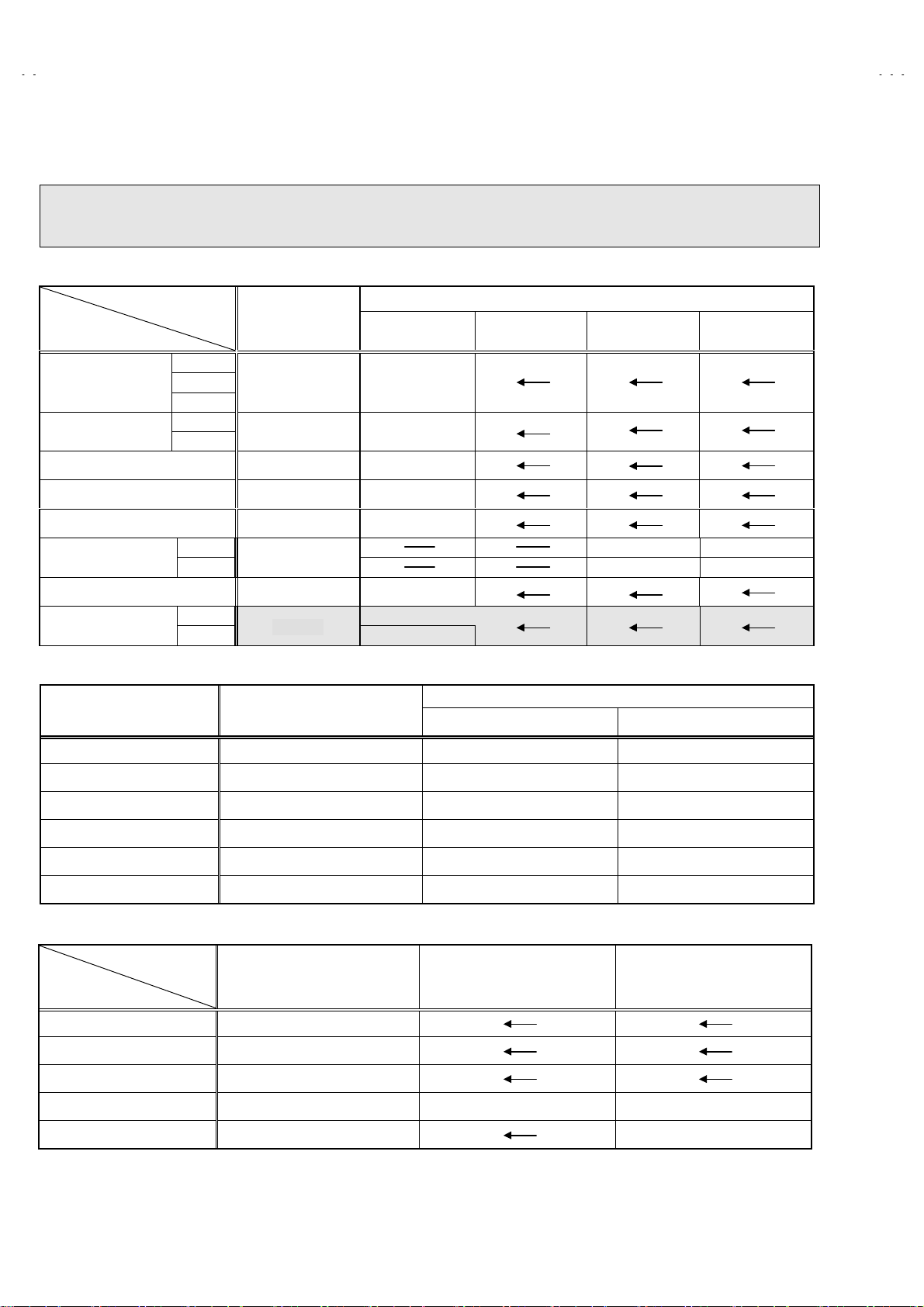
VSM PRESET SETTING
V-21LTG1
Item
Setting of
VSM
PRESET
Measuring
instrument
Remote
control unit
TINT
COLOUR
BRIGHT
CONT.
SHARP
/ :SELECT
- / + : OPERATE DISP : EXIT
Test point Adjustment part Description
BRIGHT
**
**
**
**
**
TINT
COLOUR
BRIGHT
CONT.
SHARP
1. Select
2. Select BRIGHT with the PICTURE MODE key.
3. Adjust the MENU ▼/▲ and MENU - or + k ey to bri ng the s et
4. Respectively select the VSM PRESET mode for SOFT and
4. VSM PRESET
values of TINT ~ SHARP to the values shown in the table
given before page.
STANDARD, and make similar adjustment as in 3 above.
from the SERVICE MENU.
VSM PRESET
$$$$
VSM
Setting Item
TINT +15
COLOUR +15
BRIGHT +15
CONT +30 +15 +11
SHARP +15
BRIGHT STANDARD SOFT
←
←←
←←
←
←
+12
No. 51892
27
Page 28

A
V-21LTG1
PURITY / CONVERGENCE ADJUSTMENT
PURITY ADJ USTMENT
1. Demagnet ize CRT with the demagnetizer.
2. Loosen the retainer screw of the deflection yoke.
3. Remove the w ed ges.
4. Input a green r aster signal f rom the sign al gener ator, an d turn
the screen to green raster.
5. M ove t h e def l ec tion yoke bac k w ard.
6. Brin g the long l ug of the pur ity magnets on the sh ort lug an d
position them horizontally. (Fig.2)
7. Adj us t t h e g ap b etween two lugs s o th at th e G R EEN RASTER
will come into the center of the screen. (Fig.3)
8. Move the defl ection yok e forward, and fix the position of the
deflection yoke so that the whole screen will become green.
9. Insert the wedge to the top side of the deflection yoke so that it
will not move.
CRT
WEDGE
DEFLECTION YOKE
#
P : PURITY MAGNET
4 : 4 POLES
6 : 6 POLES
Fig.1
PURITY MAGNETS
PURITY MAGNET(P)
46
P / C MAGNETS
CRT SOCKET PWB
P/C M A GNETS
(con ver g ence magn ets )
(con ver g ence magn ets )
10. Input a crosshatch signa l.
11. Verify that the sc reen is hori z ont al.
12. Inp ut red and blu e raster si gnals, and make su re that pur ity is
properly adjusted.
Short lug
Long lug
Bri n g th e l on g l u g over t h e s h or t lug
and position them horizontally.
Fig.2
(FRONT VIEW)
CENTER
Fig.3
GREEN RASTER
28
No. 51892
Page 29

A
STATIC CONVERGENCE ADJUSTMENT
1. Input a crosshatch signal.
2. Using 4- pole conver gence magn ets, overlap th e red and bl ue
lines in the center of the screen (Fig.1) and turn them to
magenta (red/blue).
3. Using 6-pole convergence magnets, overlap the magenta
(red/bl ue) and gr een li nes in th e cent er of th e screen and tur n
them to white.
4. R epeat 2 and 3 above, an d m ak e b est c on vergence.
After adj us tm ent, fix th e wed g e at th e ori gi n al p osi t i on.
Fasten the retainer screw of the deflection yoke.
Fix the 6 magn et s wit h glu e.
V-21LTG1
(FRONT VIEW)
Fig.1
DYNAMIC (periphery) CONVERGENCE
ADJUSTMENT
After adjusting purity & static convergence.
*
1. Move t he defl ecti on yok e up an d d own an d overl ap the l ines in
the periphery. (Fig.2)
2. Move the deflection yoke left to right and overlap the lines in the
periphery. (Fig.3)
3. R epeat the steps 1 an d 2 and obt ain an optim u m c on verg ence.
After adj us tm ent, fix th e wed g e at th e ori gi n al p osi t i on.
Fasten the retainer screw of the deflection yoke.
Fix the 6 magn et s wit h glu e.
(FRONT VIEW)
BLUE
GREEN
RED
(FRONT VIEW)
GREEN
RED
BLUE
RED
BLUE
YH
GREEN
GREEN
YH
Fig.2
BLUE
RED
BLUE
GREEN
RED
GREEN
BLUE
RED
RED
GREEN
BLUE
Yv
Yv
BLUE
GREEN
RED
Fig.3
No. 51892
29
Page 30

A
V-21LTG1
REPLACEMENT OF CHIP COMPONENT
CAUTIONS
!
1. Avoid heating for more than 3 seconds.
2. Do not rub the electrodes and the resist parts of the pattern.
3. When removing a chip part, melt the solder adequately.
4. Do not r euse a chip part aft er rem oving it.
SOLDERING IRON
!
1. Use a high ins ul at i on s old er in g iron with a thin pointed end of it.
2. A 30w soldering iron is recommended for easily removing parts.
REPLACEMEN T STEPS
!
How to remove Chip parts
1.
Resistors, capa citors, etc.
$
(1) As sh own in th e figure, pus h the p art with t weezers and
alternately melt th e s old er at eac h en d.
2. How to install Chip parts
Resistors, capa citors, etc.
$
(1) Apply solder to the pattern as indicated in the figure.
(2) S hif t with tweezers and remo ve th e ch ip p ar t.
Transistors, diodes, variable resistors, etc.
$
(1) Apply extra solder to each lead.
SOLDER
(2) As sh own in th e figure, pus h the p art with t weezers and
alternat ely melt th e solder at each l ead. Shift and remov e
the chip part.
SOLDER
(2) Grasp the chip part with tweezers and place it on the
solder. Then h eat and m elt the sold er at both en ds of the
chip part.
Transistors, diodes, variable resistors, etc.
$
(1) Apply solder to the pattern as indicated in the figure.
(2) Grasp the chip part with tweezers and place it on the
solder.
(3) First solder lead
(4) Then solder leads
as indicated in the figure.
A
A
B
C
and C.
B
Note : Afte r rem oving t he part, rem ove rema ining s older from
the pa ttern.
30
A
B
C
No. 51892
Page 31

VICTOR COMPANY OF JAPAN, LIMITED
HOME AV NETWORK BUSINESS UNIT 12, 3-chome, Moriya-cho, Kanagawa-ku, Yokohama, Kanagawa-prefecture, 221-8528, Japan
4
AV21LTG1-H #4
VP 0111
DP7051
 Loading...