

Page 1
No. 51859
Oct. 2001
A
V-21L41
1
COPYRIGHT © 2001 VICTOR COMPANY OF JAPAN, LTD.
AV-21L41
/BK
CONTENTS
!
SPECIFICATIONS
・・・・・・・・・・・・・・・・・・・・・・・・・・・・・・・・
・・・・・・・・・・・・・・・・・・・・・・・・・・・・・・・・・・・・・・・・・・・・・・・・・・・・・・・・・・・・・・・・
・・・・・・・・・・・・・・・・・・・・・・・・・・・・・・・・ ・・・・・・・・・・・・・・・・・・・・・・・・・・・・・
・・・・・・・・・・・・・・・・・・・・・・・・・・・・・・・・・・・・・・・・・・・・・・・・・・・・・・・・・・
・・・・・・・・・・・・・・・・・・・・・・・・・・・・・
2
!
SAFETY PRECAUTIONS
・・・・・・・・・・・・・・・・・・・・・・・・・・・・・・・・
・・・・・・・・・・・・・・・・・・・・・・・・・・・・・・・・・・・・・・・・・・・・・・・・・・・・・・・・・・・・・・・・
・・・・・・・・・・・・・・・・・・・・・・・・・・・・・・・・ ・・・・・・・・・・・・・・・・・・・・・・・
・・・・・・・・・・・・・・・・・・・・・・・・・・・・・・・・・・・・・・・・・・・・・・
・・・・・・・・・・・・・・・・・・・・・・・
3
!
FEATURES
・・・・・・・・・・・・・・・・・・・・・・・・・・・・・・・・
・・・・・・・・・・・・・・・・・・・・・・・・・・・・・・・・・・・・・・・・・・・・・・・・・・・・・・・・・・・・・・・・
・・・・・・・・・・・・・・・・・・・・・・・・・・・・・・・・ ・・・・・・・・・・・・・・・・・・・・・・・・・・・・・・・・
・・・・・・・・・・・・・・・・・・・・・・・・・・・・・・・・・・・・・・・・・・・・・・・・・・・・・・・・・・・・・・・・
・・・・・・・・・・・・・・・・・・・・・・・・・・・・・・・・ ・・・
・・・・・・
・・・
4
!
FUNCTIONS
・・・・・・・・・・・・・・・・・・・・・・・・・・・・・・・・
・・・・・・・・・・・・・・・・・・・・・・・・・・・・・・・・・・・・・・・・・・・・・・・・・・・・・・・・・・・・・・・・
・・・・・・・・・・・・・・・・・・・・・・・・・・・・・・・・ ・・・・・・・・・・・・・・・・・・・・・・・・・・・・・・・・
・・・・・・・・・・・・・・・・・・・・・・・・・・・・・・・・・・・・・・・・・・・・・・・・・・・・・・・・・・・・・・・・
・・・・・・・・・・・・・・・・・・・・・・・・・・・・・・・・ ・・
・・・・
・・
5
!
SPECIFIC SERVICE INSTRUCTIONS
・・・・・・・・・・・・・・・・・・・・・・・・・・・・・・・・
・・・・・・・・・・・・・・・・・・・・・・・・・・・・・・・・・・・・・・・・・・・・・・・・・・・・・・・・・・・・・・・・
・・・・・・・・・・・・・・・・・・・・・・・・・・・・・・・・ ・・・・・・・・・・・・・
・・・・・・・・・・・・・・・・・・・・・・・・・・
・・・・・・・・・・・・・
7
!
SERVICE ADJUSTMENTS
・・・・・・・・・・・・・・・・・・・・・・・・・・・・・・・・
・・・・・・・・・・・・・・・・・・・・・・・・・・・・・・・・・・・・・・・・・・・・・・・・・・・・・・・・・・・・・・・・
・・・・・・・・・・・・・・・・・・・・・・・・・・・・・・・・ ・・・・・・・・・・・・・・・・・・・・・
・・・・・・・・・・・・・・・・・・・・・・・・・・・・・・・・・・・・・・・・・・
・・・・・・・・・・・・・・・・・・・・・
14
!
PARTS LIST
・・・・・・・・・・・・・・・・・・・・・・・・・・・・・・・・
・・・・・・・・・・・・・・・・・・・・・・・・・・・・・・・・・・・・・・・・・・・・・・・・・・・・・・・・・・・・・・・・
・・・・・・・・・・・・・・・・・・・・・・・・・・・・・・・・ ・・・・・・・・・・・・・・・・・・・・・・・・・・・・・・・・
・・・・・・・・・・・・・・・・・・・・・・・・・・・・・・・・・・・・・・・・・・・・・・・・・・・・・・・・・・・・・・・・
・・・・・・・・・・・・・・・・・・・・・・・・・・・・・・・・ ・・・・
31
★
OPERATING INSTRUCTIONS
★
STANDARD CIRCUIT DIAGRAM
・・・・・・・・・・・・・・・・・・・・・・・・・・・・・・・・
・・・・・・・・・・・・・・・・・・・・・・・・・・・・・・・・・・・・・・・・・・・・・・・・・・・・・・・・・・・・・・・・
・・・・・・・・・・・・・・・・・・・・・・・・・・・・・・・・ ・・・・・・・・・・・・・・・・
・・・・・・・・・・・・・・・・・・・・・・・・・・・・・・・・
・・・・・・・・・・・・・・・・
2-1
SER VICE MANUAL
COLOUR FLAT TELEVISION
BASIC CHASSIS
CG
-F
Page 2
No. 51859
A
V-21L41
2
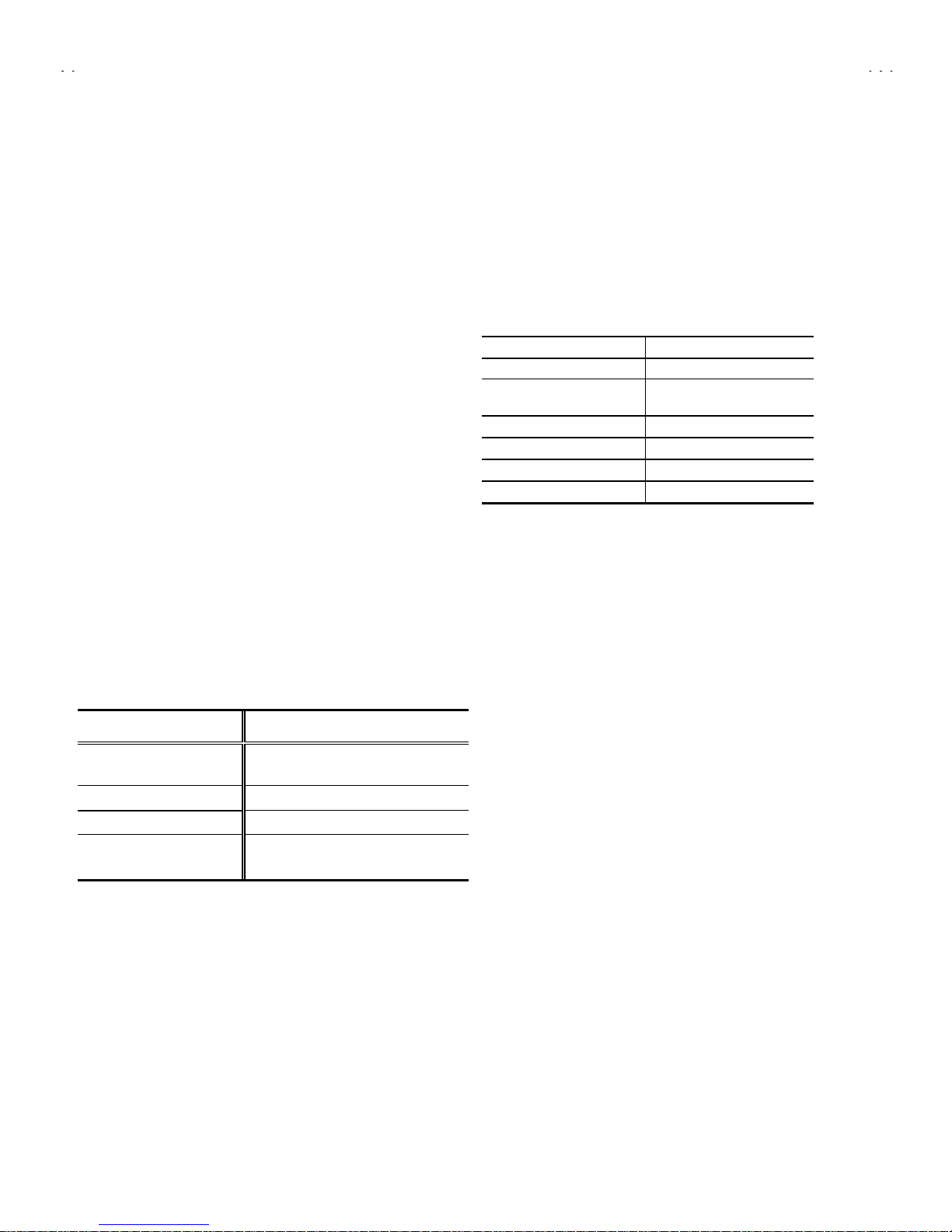
SPECIFICATIONS
ITEM
CONTENT
Dimensions(W×H×D)
598mm×468mm×471.5mm
Mass
24kg
TV RF System
B/G, I, D/K
RF Mode PAL / SECAM
Colour System
VIDEO
Mode
PAL / SECAM / NTSC3.58 / NTSC4.43
Sound System
A
2
(Bilingual) system
Receiving Frequency
VHF (VL) 46.25MHz~168.25MHz
VHF (VH) 175.25MHz~463.25MHz
UHF 471.25MHz~863.25MHz
CATV
Cable TVs of Mid (X-Z, S1 -S10 )Super (S11-S20) & Hyper (S21-S41) band s receivable
VIF Carrier 38.0MHz
Intermediate
Frequency
SIF Carrier
32.5MHz(5.5MHz)/33.5MHz (4.5MHz )
31.5MHz (6.5MHz)
Colour Sub Carrier Frequency
PAL (4.43MHz),
SECAM (4.40625MHz / 4.25MHz)
NTSC (3.58MHz / 4.43MHz)
AC110~240V, 50 / 60Hz
Power Input
Rated Voltage
Operating Voltage
AC90~260V, 50 / 60Hz
Power Consumption
105W (Max) 68W(Avg)
Picture Tube
Visible size: 51cm measured diag onally
High Voltage
26.5kV±1.5kV(at zero b eam current)
Speaker
5cm×12 cm, Oval ty p e×2
Audio Output
5W (monaural,Bilingual)
Aerial Input Terminal
75Ω Unbalanced
Input
Video 1V(p-p), 75Ω (Front / Rear)
Audio 500mV(rms) (-4dBs), High impedance, (Front / Rear)
Output
Video 1V(p-p), 75Ω(Rear)
Audio 500mV(rms) (-4dBs), Low impedance ,(Re ar)
Headphone jack
3.5mm min i jack
Remote Control Unit
RM-C365GY
(Battery size : AA / R06 / UM-3×2)
Design and specifications ar e s ubjec t to change without notic e.
Page 3
No. 51859
A
V-21L41
4
FEATURES
"
New chassis d esi gn enables us e of an int eractive on- s c r een contr ol.
"
Wide range voltage (110V~240V) AC p ow er in put.
"
With AUDIO / VIDEO INPUT & OUTPUT terminal.
"
MUTING button can reduce the audio level to zero instantly.
"
Functional remote control to operate TV set (for channel select, volume control, power ON/OFF, etc.) from a distance.
"
I
2
C bus control utilizes single chip ICs for IF, V/C, DEF. VSM PRESET, PRESET & TURBO TIMER.
"
By means of AUTO PROGRAM, the TV stations can be selected automatically and the TV channels can also be rearranged automatically.
"
The sound system has a built-in A
2
bilingual system
"
Built-in AI ECO (ECONOMY, ECOLOGY) sensor.
In accord ance with t he bright ness in a room , the brig htness and / of contrast of the pictur e can be ad justed aut omatically t o make t he
optimu m pic tu re which is easy on the eye.
"
Built – in ON TIMER, RETURN + & CHILD LOCK.
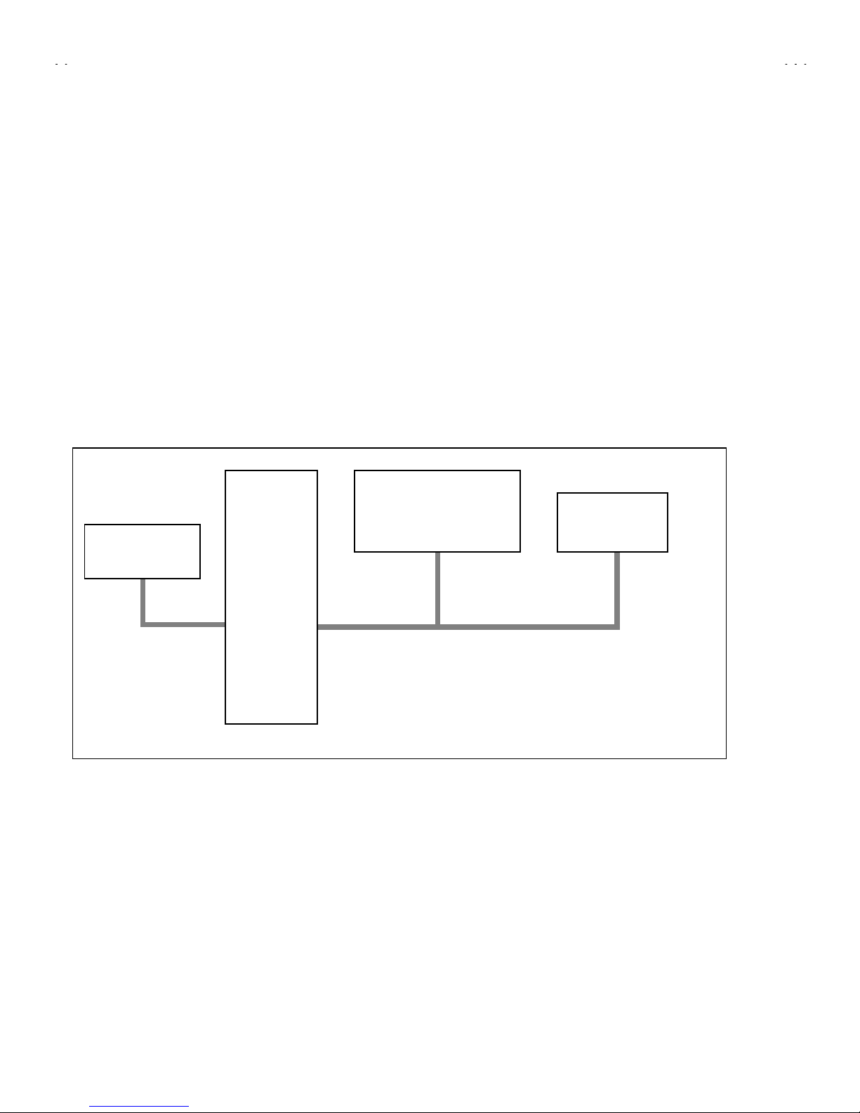
SYSTEM BLOCK DIAGRAM
IC301
VIDEO/CHROMA
DECORDER
IC702
MEMORY
TU001
TUNER
IC701
MICRO
COMPUTER
SCL1/SDA1
SCL2/SDA2
Page 4
No. 51859
A
V-21L41
5
FUNCTIONS
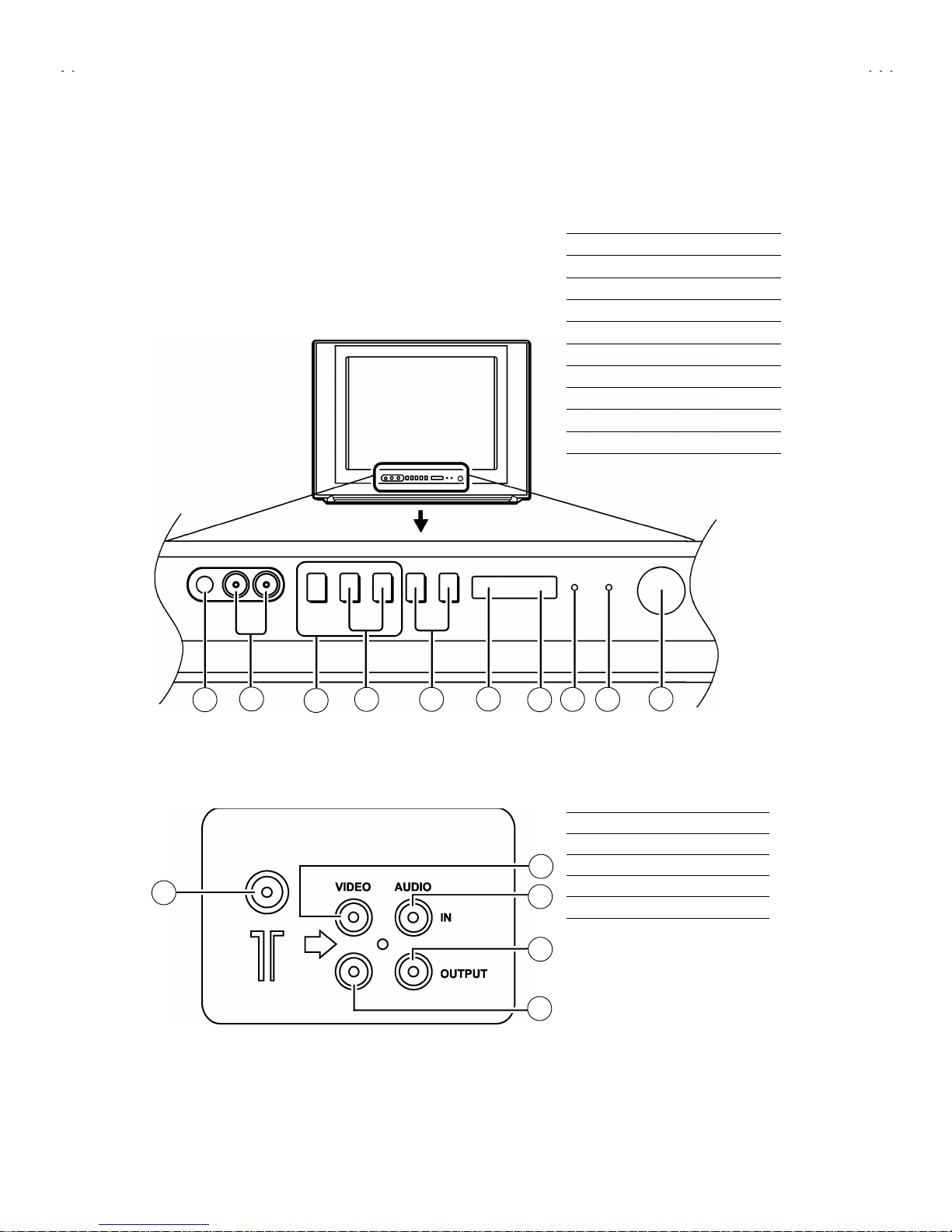
■
FRONT PANEL
■
REAR TERMINAL
①
ANT Terminal
②
VIDEO INPUT Terminal
③
VIDEO OUTPUT Terminal
④
AUDIO INPUT Terminal
⑤
AUDIO OUT PUT Terminal
▼
①
MENU buttons
②
CHANNEL -/+ buttons
③
VOLUME -/+(/EXT) buttons
④
ECO sensor
⑤
REMOTE CONTROL sensor
⑥
ON TIMER lamp
⑦
POWER lamp
⑧
MAIN POWER button
⑨
A/V INPUT terminal
⑩
HEADPHONE jack
1
8
2 3
4
5
6 7
9
10
1
2
4
5
3
Page 5
No. 51859
A
V-21L41
6
■
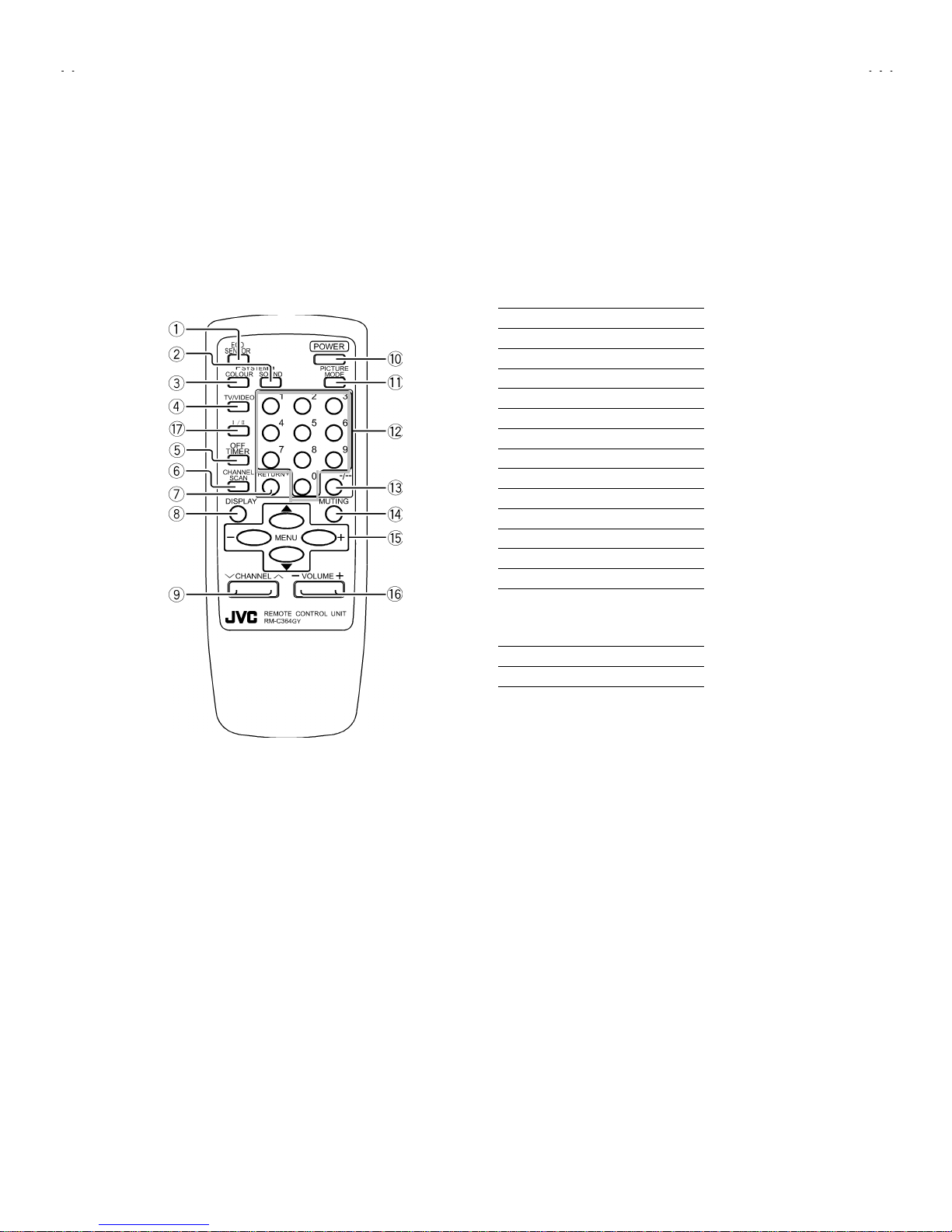
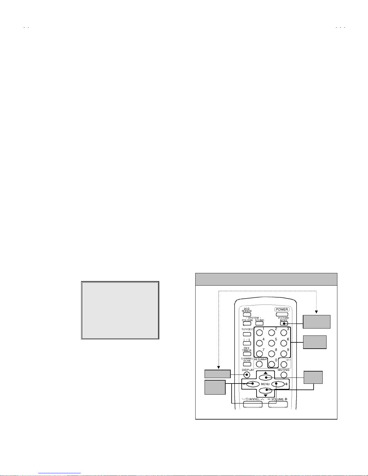
REMOTE CONTROL UNIT(RM-C365)
①
ECO SENSOR key
②
SOUND SYSTEM key
③
COLOUR SYSTEM key
④
TV/VIDEO key
⑤
OFF TIMER key
⑥
CHANNEL SCAN key
⑦
RETURN key
⑧
DISPLAY key
⑨
CHANNEL-/+ key
⑩
POWER key
⑪
PICTURE MODE key
⑫
Number (CH.) key
⑬ -/--
key
⑭
MUTING key
⑮
MENU key
MENU ▲/▼ key
MENU -/+ key
⑯
VOLUME-/+ key
⑰ Ⅰ/Ⅱ
key
+
Page 6

No. 51859
A
V-21L41
9
REPLACEMENT OF MEMORY ICs
1. MEMORY ICs
This model uses mem ory ICs. This m em ory IC data ar e f or pr op er operati on of t h e vid eo an d d ef l ec ti on cir cuits.
When replaci n g mem ory ICs , be su r e to us e ICs writ t en with the ini ti al v alues of d ata.
2. PROCEDURE FOR REPLACING MEMORY ICs
(1) Power off
Switch th e p ower off and disc onn ec t th e pow er pl ug f r om the w al l outlet.
(2) Replace ICs
Be sure to use memory ICs written with the initial data values.
(3) Power on
Connect th e power plug into the wall ou tlet and swi tc h t h e power on.
(4) Check and set SYSTEM CONSTANT SET
・・・・
It must not adjust without adjustment signals.
1) Press the
DISPLAY
key and the
PICTURE MODE
key of the REMOTE
CONTROL UNIT simultaneously.
2) T he SERVICE MEN U screen of Fig . 1 wil l b e displayed.
3) W hile the S ERVIC E MENU is dis pl ayed, ag ain pr ess the
DISPLAY
key an d
PICTURE MODE
key si multaneous ly, and th e SYSTEM CONSTAN T SET
screen of Fi g. 2 wi ll b e dis played.
4) Ch eck the set ti ng values of th e SYST EM C O N S T A NT SET of Table 1 If th e
value is dif ferent, s elect the s etting it em with the
MENU
▼/▲key, and set
the correct value with the
MENU
- / + key.
5) Press the
DISPLAY
key twice, and return to the normal screen.
(5) R ec eiv e channel of setting
Refer to the
OPERATING INSTRUCTIONS
and set the receive channels
(channels preset) as described
(6) User Setting
Check th e user sett ing val ue of T able 2, and if setting valu e is diff erent, s et
the correct value.
For setting, refer to the
OPERATING INSTRUCTIONS
.
(7) Setting of SERVICE MENU
Verify t he s etti ng it ems of the S ER VICE ME NU of T abl e 3, and r eset wher e
necessary.
For setting, refer to the
SERVICE ADJUSTMENTS
.
NOTE
Both
MENU -/+ Key and MENU
/ key have the same functions.
SERVICE MENU
1.IF 2.V/C
3.DEF 4.VSM PRESET
5.PRESET
6.TURBO TIMER O FF
1-6 SELECT DISP : EXIT
******
************
***********
**********
***** **
****
**.***
******
***
*** ** **
*** ** ***** ** **
*** ** **** ***
** ***** ***
** ***
Fig.1
Fig.2
SYSTEM CONSTANT-
ⅠⅠⅠⅠ
COLOUR
COLOURCOLOUR
COLOUR :
: :
: *****
**********
*****
BILINGUAL
BILINGUALBILINGUAL
BILINGUAL : ***
: ***: ***
: ***
TUNER
TUNERTUNER
TUNER :
: :
: **
****
**
ECO SENSOR
ECO SENSORECO SENSOR
ECO SENSOR : YES
: YES: YES
: YES
LANGUAGE
LANGUAGELANGUAGE
LANGUAGE : E/R/A/F
: E/R/A/F: E/R/A/F
: E/R/A/F
: SELECT
: OPERATE DISP : EXIT
SYSTEM CONSTANT SET 1
SYSTEM CONSTANT-
ⅡⅡⅡⅡ
B/B SOUND : NO
LOCK : 20
COLOUR AUTO : YES
QSS : MQSS
ALC : NO
TEXT RATE : 20
SYSTEM CONSTANT SET 2
:SEL
:OPE
DISP:EXIT
KEY ASSIGNMENT OF REMOTE CONTROL UNIT
MENU
▼/▲
key
MENU
-/+
key
DISPLAY ke y
PICTURE
MODE key
NUMBERS
key
Page 7
No. 51859
A
V-21L41
10
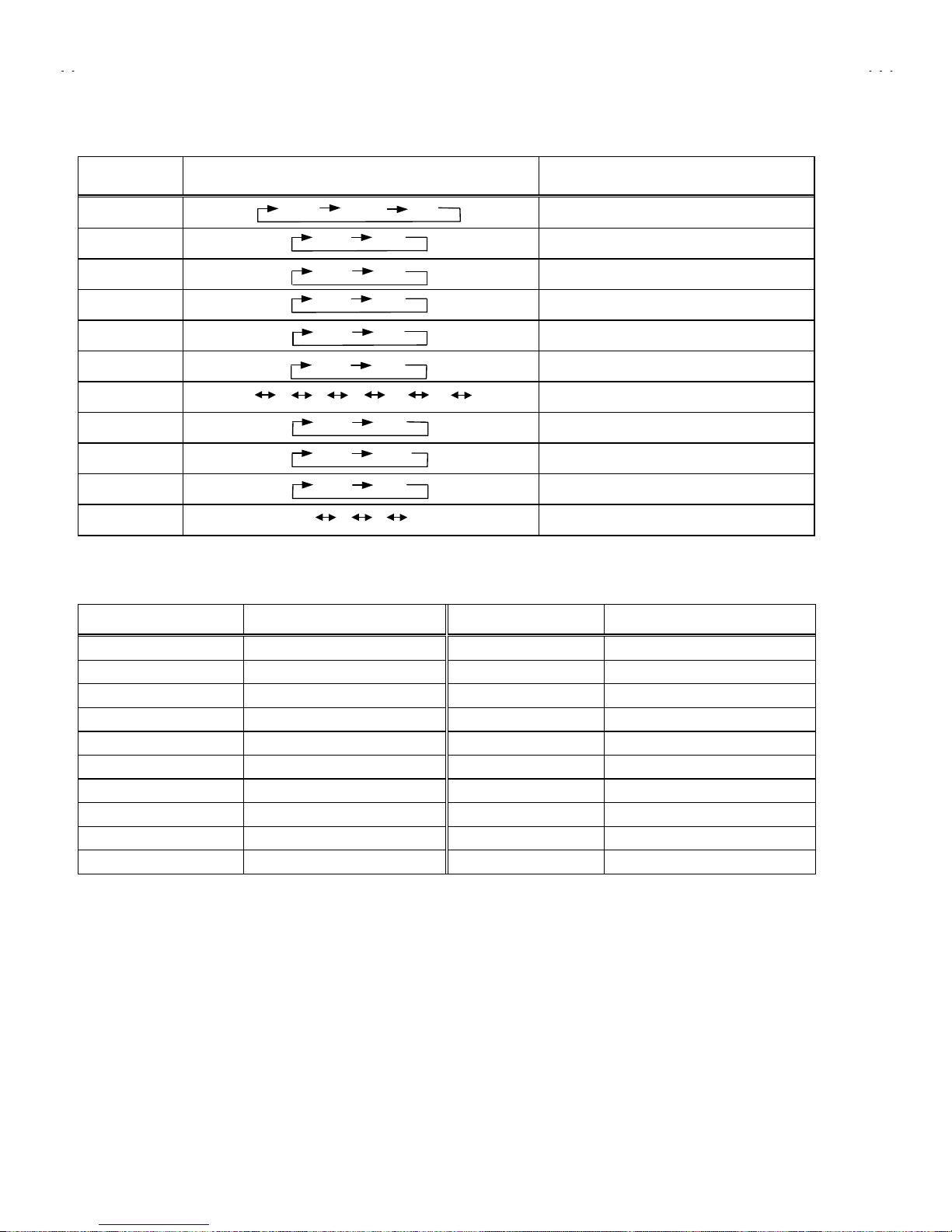
SETTING OF SYSTEM CONSTANT SET
Setting item Setting contents Setting value
COLOUR
TRIPLE
BILINGUAL
YES
TUNER
MU
ECO SENSOR
YES
LANGUAGE
E/T
B/B SOUND
NO
LOCK
YES 10 20
~
230 240 250
20
COLOUR AUTO
NO
QSS
MINT
ALC
NO
TEXT RATE
10 20 40 80 20
Table 1
USER SETTING VALUES
Setting item Setting value Setting item Setting value
MAIN POWER SW OFF PICTURE MODE (VSM) BRIGHT
SUB POWER ON LANGUAGE THAI
CHANNEL POSITION 1 POSITION CHANNEL PRESET Refer to OPERATING INSTRUCTION
VOLUME
About 10 ECO SENSOR OFF
TV/VIDEO
TV VNR OFF
ON SCREEN DISPLAY POSI TION INDICATION AUTO SHUTOFF OFF
COLOUR SYSTEM PAL ON TIMER PR1 0:00
SOUND SYSTEM B / G BLUE BACK OFF
OFF TIMER OFF ( shown : 00 ) CHILD LOCK OFF
BILINGUAL
ⅠⅠⅠⅠ(ⅠⅠⅠⅠ/ⅡⅡⅡⅡ
)
Table 2
MULTI
PAL
TRIPLE
YES NO
MU
MA
YES NO
E/T E
ON
OFF
YES
NO
MINT
MQSS
YES
NO
Page 8
No. 51859
A
V-21L41
11
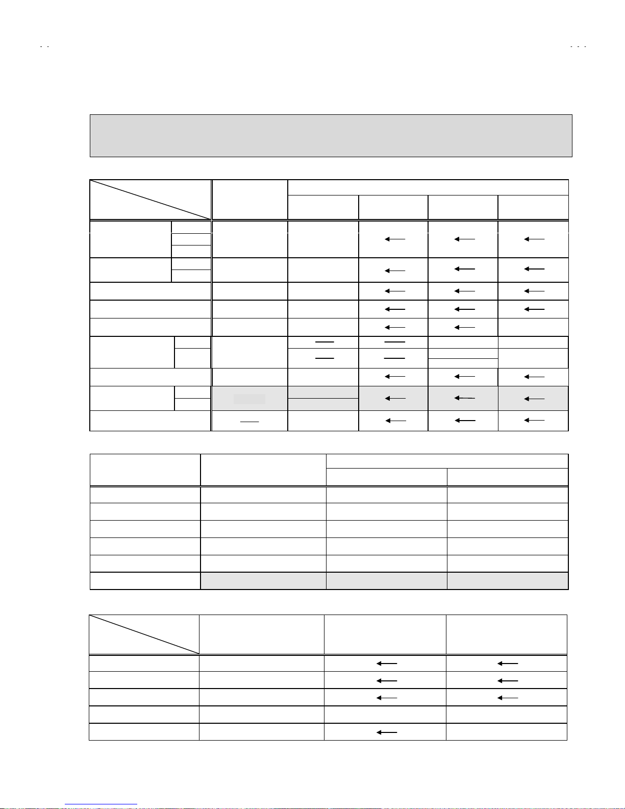
INITIAL SETTING VALUE OF SERVICE MENU
1. Adjustment of the SERVICE MENU is made on the basis of the initial setting values ; however, the new setting values which
set the screen in its optimum condition may differ from the initial setting.
2. Do not change the initial Setting Values of the Setting (Adjustment) items not listed In “ADJUSTMENT”.
2. V/C
Initial settin g value
Colour system
Setting item
Variable
range
PAL SECAM NTSC 3.58 NTSC 4.43
RED
GREEN
1. CUT OFF
BLUE
-128~+127
-50
RED
2. DRIVE
BLUE
-128~+127
+ 0
3. BRIGHT
-127~+127
+ 0
4. CONT.
-63~+63
+ 0
5. COLOUR
-63~+63
+ 0
+ 0
TV
+ 0 + 0
MU
6. TINT
VIDEO
-63~+63
+ 8
+ 0
7. SECAM BL ADJ.
-31~+31
+ 0
TV
- 7(Fixed)
8. SHARP
(Do Not Adj.)
VIDEO
-32~+31
+15(Fixed)
9. AMP T.SHARP
-12
3. DEFLECTION
Initial settin g value
Setting item Variable range
fv : 50Hz MODE fv : 60Hz MODE
1. VER. POSITION
-04 ~ +03
- 1 - 3
2. HOR. POSITION
-16 ~ +15
+ 3 + 3
3. VER. HEIGHT
-64 ~ +63
-35 + 1
4. VER. LINEARITY
-32 ~ +31
+15 - 1
5. VER. SCURVE
-32 ~ +31
-32 + 0
6. HOR. VCO ADJUST
-63 ~ +62
+ 0 + 0
4. VSM PRESET
VSM preset
VSM mode
Setting item
BRIGHT STANDARD SOFT
TINT
SETTING VALUE +15
COLOUR
SETTING VALUE +15
BRIGHT
SETTING VALUE +15
CONT.
SETTING VALUE +30 +19 +14
SHARP
SETTING VALUE +20 +15
Page 9

No. 51859
A
V-21L41
12
5. PRESET
The items in the following table, it is no requirement for adjustment.
If values had changed by the miss operation, set the initial setting values in the following table.
Colour System (Do Not Adjust)
Initial setting value (Fixed value)
Setting item
PAL SECAM NTSC 3.58 NTSC 4.43
1. C TRAP FIX
111 1
2. SHARP PEAK
000 0
3. ABL
111 1
4. GAMMA
000 0
TV
022 3
5. Y. DELAY TIME
VIDEO
020 2
6. BLACK EXP START
+
3
+
3
+
3
+
3
TV
110 0
7. C-BPF
VIDEO
111 1
8. CW / SCP
000 0
9. VIF DET LEVEL
000 0
11. IF AGC M IN
000 0
12. VIF AGC
000 0
13. VIF PMOD
000 0
19. VNR
15 15 15 15
20. RGB LIM
111 1
21. RGB LIMIT LEVEL
222 2
23. TEXT H. POSITION
-3 -3 -3 -3
24. READ DATA
Sound System ( Do Not A djust)
Setting item B/G I D/K M
10. SIF DET LEVEL
+
0
+
0
+
0
+
0
14. SIF BPF BW ADJUST
0 (-) 0 (-) 0 (-) 0 (-)
15. SIF TRAP FO ADJUST
0 (-) 0 (-) 0 (-) 0 (-)
16. SIF TRAP FO ADJUST 2
0 (-) 0 (-) 0 (-) 0 (-)
17. SIF -TR AP
000 0
18. SIF -BPF
000 1
22. SIF SW
111 0
Page 10
No. 51859
A
V-21L41
13
REPLACEMENT OF IC301 (IF V/C DECODER)
"
For the IC3 01(IF V/C DEC ODER) of this model , all data are wr itten in t he micro-c omputer . So, write t he data in the micro-
computer in ac cor d an ce w i th t he fol lowing pro c ed ur e s bef ore start ing adjust m ent.
RE PLACING PR OC ED UR ES
(1)
Turn the POWER OFF.
(2)
Replace the IC301 with a new one.
(3)
While pressing MENU button and VOL+ button ON the FRONT Panel simultaneously, turn the POWER ON. When the POWER is turned
ON, the data is writt en in th e mic ro-com pu ter immed i at ely.
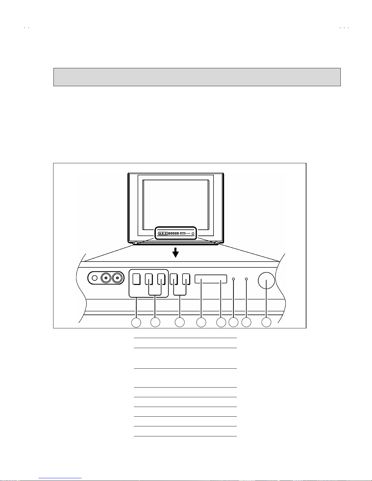
LOCATIONS OF FRONT PANEL BUTTONS AND LAMPS
1
MENU buttons
2
CHANNEL ∨/∧ buttons
(MENU ∨/∧ buttons)
3
VOLUME -/+ buttons
(MENU -/+ buttons)
4
ECO sensor
5
REMOTE CONTROL sensor
6
ON TIMER lamp
7
POWER lamp
8
MAIN POWER button
1
82 3
4 5
6 7
Page 11
No. 51859
A
V-21L41
14
SERVICE ADJUSTMENT
BEFORE STARTING SERVICE ADJUSTMENT
1. There are 2 way of adjusting this TV: One is with the
REMOTE C ONTROL UNIT a nd the oth er is t he conv ention al
method using adjustment pa rts and components.
2. The ad justm ent w ith the REM OTE C ONTROL UNIT i s mad e
on the basis of the initial setting values. The setting values
which adjust the screen to its opt i mum con dit i o n may d iff er
from the initial setting values.
3. Make sure that connection is correctly made to AC power
source.
4. Turn on the pow er of the set and equipmen t before us e, and
start the adjustment procedures after waiting at least 30 minutes.
5. Unless other wise spec ified, pr epare t he most su itab le rec eption
or input signal for adjustment.
6. Never touch any adjustment par ts, which are not s pecified
in the list for t hi s a djust men t VR s, tr an sfor ms, cond en sers,
etc.
7. Preparation for adjustment
Unless oth erwis e sp ec if ied in th e adj us tm en t i ns tr uc t i ons , pres et
the following functions with the REMOTE CONTROL UNIT.
User mode position
PICTURE MODE (VSM) BRIGHT
VNR OFF
COLOUR / BRIGHT
CONT. / SHARP
Refer to VSM PRESET
BLUE BACK OFF
OFF TIMER OFF
ECO SENSOR OFF
AUTO SHUT OFF OFF
MEASURING INSTRUMENT AND FIXTURES
1. DC voltmeter (or digital voltmeter)
2. Oscilloscope
3. Signal generator (Pat tern generator) [PAL / SECAM / NTSC]
4. Remote control unit
ADJUSTMENT ITEMS
Adjustment item Adjustment item
B1 POWER SUPPLY
DEF. circuit adjustment
FOCUS adjustment VSM PRESET setting
IF circuit adjustment
PURITY / CONVERGENCE adjustment
V/C (Video / Chroma) circuit
adjustment
Page 12
No. 51859
A
V-21L41
15
BASIC OPERATION OF SERVICE MENU
"
The adjustment using SERVICE MENU
The followi ng adjustm ent items us e the SERVICE MEN U in the seri es of the adjust ment. The adjus tments ar e made on the basis of the
initial setting values. The adjustment values which adjust the screen to the optimum condition can be different from the initial setting values.
With the SERVICE MENU, various settings can be made, and they are broadly classified in the following items of settings.
1.IF
・・・・・・・・・・・・・・・・・・・・・・・・
Adjustment of the IF circuits.
2.V/C
・・・・・・・・・・・・・・・・・・・・・・
Adjustment of the VIDEO/CHROMA circuit.
3.DEF
・・・・・・・・・・・・・・・・・・・・・
Adjustment of the DEFLECTION circuit.
4.VSM PRESET
・・・・・・・・・・・・・
Adjustm en t of th e initial sett in g val u es of VS M c on dit i on as S T A ND AR D , SO FT and BRIGH T .
(VSM : Video Status Memory)
5.PRESET
・・・・・・・・・・・・・・・・・
Adju stment of the RF circuit
[Do not adjust]
.
6.TURBO TIMER
・・・・・・・・・・・・
For quick s ett i ng t h e TIME R count val u e, adjustable not onl y b y mi nuets but also by second.
[Should be OFF]
.
"
Key operation of the SERVICE MENU
[Enter to SERVICE MENU]
Press the
DISPLAY
key and th e
PICTURE M ODE
key of the REMOTE CONTROL
UNIT simultaneously. Then enter the SERVICE MENU mode as shown in Fig.1.
[Exit from SERVICE MENU]
When complete the adjustment work, press the
DISPLAY
key to return to the
SERVICE MENU.
And then press the
DISPLAY
key again, return to the normal screen.
[Select from SERVICE MENU]
In SERVICE MENU , pr ess the numb er (1~6) key of the remote control unit, to select
any of the adj us t m en t items.
SERVICE MENU
SERVICE MENU
1.IF 2.V/C
3.DEF 4.VSM PRESET
5.PRESET
6.TURBO TIMER O FF
1-6 SELECT DISP : EXIT
******
************
***********
**********
***** **
****
**.***
******
***
*** ** **
*** ** ***** ** **
*** ** **** ***
** ***** ***
** ***
Fig.1
KEY ASSIGNMENT OF REMOTE CONTROL UNIT
MENU
▼/▲
key
MENU
-/+
key
DISPLAY ke y
PICTURE
MODE key
NUMBERS
key
Page 13

No. 51859
A
V-21L41
16
[Method of setting]
1. IF
[1. VCO]
①
1 Key
・・・・・・・・・・・・・・・・・・・・・・・・・
Selec t
1.IF
.
②
1 Key
・・・・・・・・・・・・・・・・・・・・・・・・・
Selec t
1.VCO
③
The VCO (CW) screen w il l be dis p l ay ed a allow mark wh en the AF C vol tag e is at a c ertain level .
④
DISPLAY Key
・・・・・・・・・・・・・・・・・
When this is press twice, you will retu rn to the
SERVICE MENU
.
[2. DELAY POINT]
①
1 Key
・・・・・・・・・・・・・・・・・・・・・・・・・
Selec t
1.IF
.
②
2 Key
・・・・・・・・・・・・・・・・・・・・・・・・・
Selec t
2.DELAY POINT
.
③
MENU -/+
・・・・・・・・・・・・・・・・・・・・・
Set (adjust) the setting values of the setting items.
④
DISPLAY Key
・・・・・・・・・・・・・・・・・
When this is pressed, you will return to the
SERVICE MENU
.
2.V/C, 3.DEF
and
4.VSM PRESET
①
2~4Key
・・・・・・・・・・・・・・・・・・・・・・・
Select on e from
2. V/C, 3. DEF
and
4. VSM PRESET
.
②
MENU ▼/▲ Key
・・・・・・・・・・・・・・
Select setting items.
③
MENU -/+
・・・・・・・・・・・・・・・・・・・・・
Adjust the values of the items.
④
DISPLAY Key
・・・・・・・・・・・・・・・・・・
When this is pressed, return to the
SERVICE MENU
.
6.TURBO TIMER
①
By pressing the 6 key, you can change the ON or OFF (
should be OFF
).
(Should be OFF)
%
If it is ON, the timer in TIMER mode changes from 1 minute into 1 sec tem p orarily.
(It is easier to checks the Operation of TIMER)
If you turn the TV power off, this setting becomes OFF automatically.
Page 14

No. 51859
A
V-21L41
17
SERVICE MENU FLOW CHART
SERVICE MENU
IF
1. VCO
2. DELAY POINT
1-2 : SELECT DISP : EXIT
SUB MENU 1. IF
VCO (CW)
***.**
MHz
TOO HIGH
ABOVE REFERENCE
JUST REFERENCE
BELOW REFERENCE
TOO LOW
AFT ADJUST
***(**)
***(**)***(**)
***(**)
VCO ADJUST
***(**)
***(**)***(**)
***(**)
FINE
DISP : EXIT
DELAY POINT UHF
AGC TAKE-OVER
**
- / + : OPERATE DISP : EXIT
6.TURBO TIMER
ON /
OFF
(By pressing 6-key)
SERVICE MENU
1.IF 2.V/C
3.DEF 4.VSM PRESET
5.PRESET
6.TURBO TIMER OFF
1-6 SELECT DISP : EXIT
******
************
****** *****
**********
***** **
****
**.***
******
***
*** ** **
*** ** ***** ** **
*** ** ** ** ***
** ***** ***
** ***
OFF
V/C PAL
1. CUTOFF
- / + : OPERATE DISP : EXIT
(R)
* **
(G)
* **
(B)
* **
50Hz
SUB MENU 2. V/ C
/ :SELECT
DEF
- / + : OPERATE DISP : EXIT
***
SUB MENU 3. DEF
/ :SELECT
50Hz
1. VER. POSITION
PAL
PRESET
1. C-TRAP FIX
- / + : OPERATE DISP : EXIT
***
50Hz
SUB MENU 5. PRESET
/ :SELECT
B/G
PAL
BRIGHT
TINT
COLOUR
BRIGHT
CONT.
SHARP
- / + : OPERATE DISP : EXIT
**
**
**
**
**
SUB MENU 4. VSM PRESET
/ :SELECT
Page 15

No. 51859
A
V-21L41
18
ADJUSTMENT LOCATIONS
S
1Pin TP-91(B1
)
2Pin NC
3Pin X-ra
y
1
4Pin X-ra
y
2
5Pin TP-E
(
)
HVT
S
1
HV
U
IC301
MEMORY IC
IC702
IC701
F901
DEG
TU001
FRONT
TOP
MAIN PWB
CRT SOCKET PWB
(
SOLDER SIDE
)
TP-47G/R
E1
U
T
PW
UPPER:FOCUS
LOWER:SCREE N
TP-47R/G
TP-47B
TP-E
T
CRT EARTH WIRE
(BRAIDED ASS'Y)
A/V INPUT
Headphone
ANT. Terminal
A/V IN&OUTPUT
Terminal
POWER
SW
Page 16

No. 51859
A
V-21L41
19
ADJUSTMENTS
B1 POWER SUPPLY
Item
Measuring
instrument
Test point Adj ustment part Descrip tion
Check of
B1 Power
Supply
Signal
generator
DC Vol t meter
TP-91 (B1)
TP-E (
####
)
1. Input a whol e blac k sig n al.
2. Connect a DC voltmeter to TP-91(B1) and TP-E (#).
3. Make sure that the voltage is DC114.5±1.5V.
FOCUS ADJUSTME NT
Item
Measuring
instrument
Test point Adj ustment part Descrip tion
Adjustment
of FOCUS
Signal
generator
FOCUS VR
[In HVT]
1. Input a cross-hatch signal.
2. While watching th e screen, adjust the FOCU S VR to m ake the
vertic al and hor i z ont al lines as fin e and s harp as possible.
3. Make sure that when the screen is darkened, the lines remain in
good focus.
IF CIRCUIT ADJUSTMENT
Item
Measuring
instrument
Test point Adj ustment part Descrip tion
●
Please use signal generator which is correct proof about the
sending frequency.
Adjustment
of VCO(CW)
Signal
generator
Remote
control unit
1. VCO
1. Input the PAL full colour bar (210.25MHz) signal.
2. Select 1.IF from the
SERVICE MEN U
.
3. Press 1 key and select
1.VCO
.
4. Select
VCO ADJUST
with
MENU
▲/▼ key.
5. Press
MENU
-/+ key until the colour of the characters TOO
HIGH chang es b lu e to yell ow. T h en gr adu all y pr ess th e
MENU
-/+ key until the TOO LOW changes yellow. At this time, confirm
th a t th e valu e of
VCO ADJUST
is near +00.
6. Select
AFT A D JUST
with
MENU
▲/▼ key.
7. Press
MENU
-/+ k ey until th e characters JUST REFE RENCE
changes blue to yellow.
8. Press the
DISPLAY
key th ree times to return to normal screen.
VCO (CW)
***.**
MHz
TOO HIGH
ABOVE REFERENCE
JUST REFERENCE
BELOW REFERENCE
TOO LOW
AFT ADJUST
***(**)
***(**)***(**)
***(**)
VCO ADJUST
***(**)
***(**)***(**)
***(**)
FINE
DISP : EXIT
YELLOW
Do not ad
j
ust
ADJUSTMENT AT THIS POINT IS USEL ESS
ABOVE REFERENCE
TOO HIGH
BELOW REFERENCE
JUST REFERENCE
TOO LOW
ADJUSTMENT POINT
Page 17

No. 51859
A
V-21L41
20
Item
Measuring
instrument
Test point Adj ustment part Descrip tion
Adjustment
of DELAY
POINT
(AGC)
Signal
generator
Remote
control unit
DELAY POINT
(AGC TAKE-OVER)
1. Inp ut a black and w hit e signal (colour off).
2. Select
1. IF
from the SERVICE MENU.
3. Select
2. DELAY POINT
by pres sing t he 2 key on the remote
control un it.
4. Set the setting values of the setting items as shown bellow
tabbe.
5. T hen ad just the MEN U - or + key u nt i l vid e o noise dis app ear s .
6. Turn to other channels and make sure that there are no
irregularities.
Setting Item Variable range Initial setting value
MU
NTSC 3 . 5 8
48
DELAY POINT
(AGC TAKE OVER)
OTHER
0~127
43
DELAY POINT UHF
AGC TAKE-OVER
**
- / + : OPERATE DISP : EXIT
Page 18

No. 51859
A
V-21L41
21
VIDEO / CHROMA CIRCUIT ADJUSTMENT
The setting (adjustment) using the REMOTE CONTROL UNIT is made on the basis of the initial setting values.
The setting values which adjust the screen to the optimum condition can be different from the initial setting values.
Do not change the initial setting values of the setting items not listed in “ADJUSTMENT”.
Item
Measuring
instrument
Test point Adj ustment part Descrip tion
Adjustment
of WHITE
BALANCE
(Low light)
Signal
generator
Remote
control unit
1. CUT OFF (R)
CUT OFF (G)
CUT OFF (B)
SCREEN VR
[IN HVT]
1. Inp ut a black and w hit e signal (colour off).
2. Select
2. V/C
from the SERVICE MENU, then select
1. CUT
OFF
(R), (G) and (B) .
3. Set each value to initial setting value with 4~9 keys of the
remote control unit.
4. Press th e
1
key of the rem ote contr ol unit to show the singl e
horizontal line on screen.
5. Turn the
SCREEN VR
fully counte r - clockwi se, the n slo w ly tu r n i t
clockwis e to where one of a red, blue or gr een colour is f aintly
visible.
6. Use keys
4~9
of the r em ote cont r ol unit and adjus t the oth er 2
colours which except th e appeared c olour to wh ere the singl e
horizontal line appears white.
7. Turn the
SCREEN VR
to where the single horizontal line glows
faintly.
8. Press the
2
key to turn of f the si ngle horiz on tal line.
9. Press the
DISPLAY
key twice to return to the normal screen.
Adjustment
of WHITE
BALANCE
(High light)
Signal
generator
Remote
control unit
2. DRIVE (R
)
DRIVE (B)
1. Input a black an d w hit e si gnal (c olour of f ).
2. Select
2. V/C
from the SERVICE MENU.
3. Select
2. DRIVE (R) / (B)
with MEN U ▼/▲ key, and set each
value to i niti al set ting val ue wit h 4 and 7 or 6 and 9 keys of th e
remote control unit.
4. Use the keys
4
and 7 or 6 and 9 to produc e a wh it e sc reen
5. P ress the DISP L AY key twice to retu rn to the nomal screen.
Adjustment item
Variable
range
Initial settin g
value
R
-128~+127
-50
G
-128~+127
-50
1. CUT OFF
B
-128~+127
-50
Adjustment item
Variable
range
Initial settin g
value
R
-128~+127
+0
2. DRIVE
B
-128~+127
+0
V/C PAL
1. CUTOFF
- / + : OPERATE DISP : EXIT
(R)
* **
(G)
* **
(B)
* **
50Hz
/ :SELECT
123
4
56
7
8
9
CUTOFF ON
(
H.LINE ON
)
CUTOFF OFF
(
H.LINE OFF
)
R. CUTOFF(
)
▲
R. DRIVE(
)
R. CUTOFF(
)
R. DRIVE(
)
▼
R
GB
G.CUTOFF(
)
▲
B. CUTOFF(
)
▲
B. DRIVE(
)
▲
▲
B. CUTOFF(
)
B. DRIVE(
)
G.CUTOFF(
)
▼
▲
▲
▲
KEY ASSIGNMENT OF REMOTE CONTROL UNIT
V/C PAL
2. DRIVE
- / + : OPERATE DISP : EXIT
(R)
* **
(B)
* **
50Hz
/ :SELECT
Page 19

No. 51859
A
V-21L41
22
Item
Measuring
instrument
Test point Adj ustment part Descrip tion
Adjustment
of
SUB BRIG HT
Remote
control unit
3. BRIGHT
1. Receive any broadcast.
2. Select
2. V/C
from SERVICE MENU.
3. Select
3. BR I GHT
with the MENU ▼/▲key.
4. S et th e init ial setti ng val u e wit h t h e MEN U - or + k ey.
5. If the brigh tness is n ot the best w ith the initi al set valu e, make
fine adjus t m ent until you get th e bes t bri ghtness.
Adjustment
of
SUB CONT.
Remote
control unit
4. CONT.
1. Receive any broadcast.
2. Select
2. V/C
from SERVICE MENU.
3. Select
4. CONT
. with the MENU ▼/▲key.
4. S et th e init ial setti ng val u e wit h t h e MEN U - or + k ey.
5. If the contrast is not the best with the initial set value, make fine
adjust m ent un til you get th e bes t c ont r as t.
5. COLOUR [Method of adjustment without measuring instrument]
PAL COLOUR
1. R ec eive a PA L broadcast.
2. Select
2. V/C
from the SERVICE MENU.
3. Select
5. COLOUR
with th e MENU ▼/▲ key.
4. Set the initial setting value for PAL COLOUR with the MENU -
or + key.
5. If the colour is not the best with the initial set valu e, make fine
adjust m ent un til you get th e bes t c olour.
SECAM COLOUR
1. Receive a SECAM broadcast.
2. M ak e fin e adj us tm en t of SE CAM COLOUR as previ ous l y.
NTSC 3.58 COLOUR
1. Receive a NT S C 3. 58 MHz broadcast.
2. Make similar fine adjustment of NTSC 3.58 COLOUR as
previously.
Adjustment
of
SUB
COLOUR
ⅠⅠⅠⅠ
Remote
control unit
NTSC 4.43 COLOUR
When NTSC 3.58 adjustment completed, NTSC 4.43 will be
automatically set at the respective values.
Page 20

No. 51859
A
V-21L41
23
Item
Measuring
instrument
Test point Adj ustment part Descrip tion
5. COLOUR [Method of adjustment using measuring instrument]
PAL COLOUR
1. Input a PAL full field colour bar signal (75% white).
2. Select
2. V/C
from SERVICE MENU.
3. Select
5. COLOUR
with th e MENU ▼/▲ key.
4. S et th e init ial setti ng val u e of PAL CO LOU R with th e MENU
- or + key.
5. Connect the oscilloscope between TP-47G/R and TP-E (#).
6. Adj ust PAL COLOUR to bring th e val ue of
(A)
in the illustration
to +9V(W-G). (Voltage value b etween (W) and (G))
SECAM COLOUR
1. Input a SECAM full field colour bar signal (75% white).
2. Set the initial setti ng valu e of SECAM CO LOU R with the MENU
- or + key.
3. Adjust SECAM COLOUR to bring the value of
(A)
in the
illustr ati on to +6V(W-G). (V oltag e val ue betwe en (W) and (G))
NTSC 3.58 COLOUR
1. Input a NTSC 3.58 full field colour bar signal (75% white).
2. Set the initial setting value of NTSC 3.58 COLOUR wit h the
MENU - or + key.
3. Adjust NTSC 3 .58 COLOUR to b ring the val ue of
(A)
in the
illustr ati on to +8V(W-G). (V oltag e val ue betwe en (W) and (G))
Adjustment
of SUB
COLOUR
ⅡⅡⅡⅡ
Signal
generator
Oscilloscope
Remote
control unit
TP-47G/R
TP-E (
####
)
[CRT SOCKET
PWB]
NTSC 4.43 COLOUR
When NTSC 3.58 is set, NTSC 4.43 will be automatically set at the
respective values.
W
Y
Cy
G
Mg
R
B
(A)
0V
(-)
(+)
Page 21

No. 51859
A
V-21L41
24
Item
Measuring
instrument
Test point Adj ustment part Descrip tion
6. TINT [Method of adjustment without measuring instrument]
NTSC 3.58 TINT
1. Input a NTSC 3.58 full field colour bar signal (75% white).
2. Select
2. V/C
from SERVICE MENU.
3. Select
6. TINT
with th e MENU ▼/▲ key.
4. S et the init ial s etti ng valu e of NT SC 3.58 wit h the ME NU - or +
key.
5. If you c annot get the b est t i nt w it h the initial s ettin g value, m ak e
fine adjustment until you get the best tint.
Adjustment
of TINT
ⅠⅠⅠⅠ
Signal
generator
Remote
control unit
NTSC 4.43 TINT
When NTSC 3.58 is set, NTSC 4.43 will be automatically set at the
respective values.
6. TINT [Method of adjustment using measuring instrument]
NTSC 3.58 TINT
1. Input a NTSC 3.58 full field colour bar signal (75% white).
2. Select
2. V/C
from SERVICE MENU.
3. Select
6. TINT
with th e MENU ▼/▲ key.
4. S et the init ial s etti ng valu e of NT SC 3.58 wit h the ME NU - or +
key.
5. Connect the oscilloscope between TP-47G/R and TP-E. (#).
6. Adjust NTSC 3.58 TINT to bring the value of
(B)
in the
illustr ati on +7V(W -
Cy
). (Voltage value between (W) and (Cy))
Adjustment
of TINT
ⅡⅡⅡⅡ
Signal
generator
Oscilloscope
Remote
control unit
TP-47G/R
TP-E (
####
)
[CRT
SOCKET
PWB]
NTSC 4.43 TINT
When NTSC 3.58 is set, NTSC 4.43 will be automatically set at the
respective values.
W
Y
C
y
G
Mg
R
B
(B)
0V
(-)
(+)
Page 22

No. 51859
A
V-21L41
25
Item
Measuring
instrument
Test point Adj ustment part Description
[Method of adjustment using measuring instrument]Adjustment
of SECAM
BLACK
OFFSET
Remote
control unit
Signal
generator
7.SECAM
BL ADJUST
1. Receive a SECAM full field colour bar signal.
2. Select
2. V/C
from SERVICE MENU.
3. Select
7. SECAM BL AD JUST
with ▼/▲MENU key.
4. S et th e initial sett i ng val ue with the – or + MEN U key.
5. Switch the ①key (c olour OF F) and ②key (colour ON) on the
remote c ontrol an d make s ure that there is no colour on th e
black and w hite screen.
6. If the black and w hite screen is not best with t he initial s etting
value, make fine adjustment until you get th e best blac k and
white screen.
7. While watching the screen, adjust the value to be the same
colour b etween ON & OFF by t en key on the remot e control
unit.
8. Press th e DISPLAY key twice to return to the normal screen.
KEY ASSIGNMENT OF REMOTE CONTROL UNIT
123
4
56
7
8
9
COLOUR
ON
COLOUR
OFF
Page 23

No. 51859
A
V-21L41
26
DEFLECTION CIRCUIT ADJUST MENT
"
There are 2 modes of adjustment (setting value) ------ ① 50Hz mode and ② 60Hz mode ----- depending upon the kind of signals
(vertical frequency 50Hz / 60Hz).
"
When adjus ted in mode ① , mode ② will be automatically set.
The setting (adjustment) using the REMOTE CONTROL UNIT is made on the basis of the initial setting values.
The setting values which adjust the screen to the optimum condition can be different from the initial setting values.
Item
Measuring
instrument
Test point Adj ustment part Descrip tion
Adjustment
of
####
V.HEIGHT
&
V.POSITION
Signal
generator
Remote
control unit
1. VER. POSITION
3. VER. HEIGHT
1. Inp ut a cir c l e p attern sign al .
2. Select
3. DEF.
from SERVICE MENU.
3. Select
1. VER. POSITION
with th e MENU ▼/▲ key.
4. Set the initial setting value with the MENU - / + key.
5. Adjust V and V’ to be equal with the MENU - / + key as shown
in Fig.2.
6. Input a cross- hatch signal.
7. Select
3. V. HEIGHT
with the MENU ▼/▲ key.
8. Set the initial setting value with the MENU - / + key.
9. As shown i n F ig.1, adj ust
VER. HEIGHT
and mak e th e ver tic al
screen size
92%
of the picture size with the MENU - / + keys of
remote control unit.
Adjustment
of
####
HOR.
POSITION
Signal
generator
Remote
control unit
2.HOR. POSITION
10. Inp ut a cir c l e p attern sign al .
11. Select
2. HOR POSITION
with the MENU ▼/▲ key.
12. Set the initial setting value of
2. HOR. POSITION
with the
MENU - / + key.
13. Adjust
2. HOR. POSITION
to make
H=H"
as show n in Fig. 2
with the MENU - / + key.
Screen size
Picture size 100%
Screen
size
92%
Picture
size
100%
Fig.1
HH"
Fig.2
V
V'
DEF
- / + : OPERATE DISP : EXIT
***
SUB MENU 3. DEF
/ :SELECT
50Hz
1. VER. POSITION
PAL
Page 24

No. 51859
A
V-21L41
27
Item
Measuring
instrument
Test point Adj ustment part Descrip tion
●●●●
When the vertical linearity has been deteriorated
remarkably, perform the following steps.
14. Input a cross-hatch signal.
15. Select
4. VER. LIN.
with the MENU ▼/▲ key.
16. Set the initial setting value of
4. VER LIN.
with the MENU - / +
key.
17. Select
5. VER. SCURVE
with the MENU ▼/▲ key.
18. Set the initial setting value of
5. VER. SCURVE
with the
MENU - / + key.
19. Adjust
4. VER. LI N.
and
5. VER. SCURVE
so that the spaces
of each line as shown in Fig.3 on
TOP, CENTER
and
BOTTOM
become uniform.
.
Adjustment
of VER. LIN.
& VER.
SCURVE
Signal
generator
Remote
control unit
4. VER. LIN.
5. VER. SCURVE
Make sur e th at the ad just ment is prop erly d one on the sc reen of
60Hz mod e.
[NOTE]
"
Adjust t o m ake bot h 50H z & 60H z ar e th e same v. siz e and
fine straight line.
"
When adjus t ag ai n, adjust 50H z m od e firs t.
"
When adjus t in 60H z m od e, onl y 60Hz mode is adj ust.
VSM PRESET SETTING
Item
Measuring
instrument
Test point Adj ustment part Descrip tion
Setting of
VSM
PRESET
Remote
control unit
TINT
COLOUR
BRIGHT
CONT.
SHARP
1. Select
4. VSM PRESET
from the SERVICE MENU.
2. Select BRIGHT with the PICTURE MODE key.
3. Adjust the MENU ▼/▲ and MENU - or + key t o bring the s et
val ues of
TINT
~~~~
SHARP
to the valu es shown in t he below
table.
4. Respectively select the VSM PRESET mode for SOFT and
STANDARD, and make similar adjustment as in 3 above.
TOP
CENTER
BOTTOM
Fig.3
BRIGHT
TINT
COLOUR
BRIGHT
CONT.
SHARP
- / + : OPERATE DISP : EXIT
**
**
**
**
**
/ :SELECT
$$$$
VSM PRESET
VSM
Setting Item
BRIGHT STANDARD SOFT
TINT +15
←
←
COLOUR +15
←←
BRIGHT +15
←←
CONT +30 +19 +14
SHARP +20
←
+15
Page 25

No. 51859
A
V-21L41
28
PURITY, CONVERGENCE
PURITY ADJUSTMENT
1. Demagne tize CRT with the demagnetizer.
2. Loosen the retainer screw of the deflection yoke.
3. Remo ve the wedg es.
4. Inp ut a green rast er signal fr om the signal g enerat or, and tur n
the screen to green raster.
5. Move t h e deflecti on yoke backw ard.
6. Bring t he long lug of the purit y magnets on the shor t lug and
position them horizontally. (Fig.2)
7. Adjus t the gap b etween two lugs s o th at the GR EE N R A ST E R
will come into the center of the screen. (Fig.3)
8. Move the deflec tion yoke forward, and fix the pos ition of the
deflection yoke so that the whole screen will become green.
9. Insert the wedge to the top side of the deflection yoke so that it
will not move.
10. Input a crosshatch signal.
11. Verify that the sc r een is hor i z ont al.
12. Inp ut red and blu e raster si gnals, and make su re that pur ity is
properl y adjusted.
P : PURITY MAGNET
4 : 4 POLES
(con vergence m agn et s )
6 : 6 POLES
(con vergence m agn et s )
Fig.1
Fig.3
Fig.2
PURITY MAGNETS
Lon
g
lu
g
Short lu
g
Bring the long lug over the short lug
and position them horizontally.
(FRONT VIEW)
GREEN RASTER
CENTER
WEDGE
P / C MAGNETS
46
CRT
DEFLECTION YOKE
CRT SOCKET PWB
PURITY MAGNET(P)
#
P/C M AGNE TS
Page 26

No. 51859
A
V-21L41
29
STATIC CONVERGENCE ADJUSTMENT
1. Input a crosshatch signal .
2. Using 4-p ole converg ence magnets , overlap the red an d blue
lines in the center of the screen (Fig.1) and turn them to
magenta (red/blue).
3. Using 6-pole convergence magnets, overlap the magenta
(red/blu e) and gr een li nes in th e cent er of th e screen and tur n
them to white.
4. Repeat 2 and 3 above, and make best c on vergence.
After adj us tm en t , fi x t h e wed g e at th e ori gi n al positi on.
Fasten the retainer screw of the deflection yoke.
Fix the 6 magn ets w ith glue.
DYNAMIC (periphery) CONVERGENCE
ADJUSTMENT
*
After adjusting purity & static convergence.
1. Move th e deflec tion yok e up an d down an d over lap th e lines in
the periphery. (Fig.2)
2. Move the deflection yoke left to right and overlap the lines in the
periphery. (Fig.3)
3. Repeat t h e steps 1 an d 2 and obtain an opt im u m c on verg ence.
After adj us tm en t , fi x t h e wed g e at th e ori gi n al positi on.
Fasten the retainer screw of the deflection yoke.
Fix the 6 magn ets w ith glue.
Fig.2
Fig.1
(FRONT VIEW)
(FRONT VIEW)
RED
GREEN
YH
BLUE
BLUE
GREEN
RED
RED
GREEN
BLUE
YH
RED
GREEN
BLUE
(FRONT VIEW)
RED
GREEN
BLUE
RED
GREEN
BLUE
RED
GREEN
BLUE
BLUE
GREEN
RED
Yv
Yv
Fig.3
Page 27

AV-21L41
No.51859
AV-21L41
STANDARD CIRCUIT DIAGRAM
NOTE ON USING CIRCUIT DIAGRAMS
1.SAFETY
The components identified by the symbol and shading are
critical for safety. For continued safety replace safety critical
components only with manufactures recommended parts.
2.SPECIFIED VOLTAGE AND WAVEFORM VALUES
The voltage and waveform values have been measured under the
follo wing conditions.
(1)Input signal : Color bar signal
(2)Setting positions of
each knob/button and
variable resistor
(3)Internal resistance of tester
:DC 20k
/V
(4)Oscilloscope sweeping time
:H
20µS/div
:V
5mS/div
:Others
Sweeping time is
specified
(5)Voltage values
:All DC voltage values
Since the vol ta ge val ue s of si gn al cir cui t va ry to some ex ten t
according to adjustments, use them as reference values.
3.INDICATION OF PARTS SYMBOL [EXAMPLE]
In the PW board
:R1209
R209
4.INDICATIONS ON THE CIRCUIT DIAGRAM
(1)Resistors
Resistance value
No unit :[
]
K
:[K
]
M
Rated allowable power
No indication :1/ 16 [W]
Others :As specified
Typ e
No indication
:Carbon resistor
OMR
:Oxide metal film resistor
MFR
:Metal film resi stor
MPR
:Metal plate resistor
UNFR
:Uninflammable resistor
FR
:Fusible resistor
Compos ition resistor 1/2 [W] is specified as 1/2S or Comp.
(2)Capacitors
: Original setting position
when shipped
5.N OT E FOR RE PAIRING S ERVICE
This model's power circuit is par tly different in the GND. The
difference of the GND is shown by the LIVE : ( ) side GND and the
ISOLATED(NEUTRAL) : ( ) side GND.Therefore, care must be
taken for the following points.
(1)Do not touch the LIVE side GND or the LIVE side GND and the
ISOLATED(NEUTRAL) side GND simultaneously. If the above
caution is not respected, an electric shock may be caused.
Therefore, make sure that the power cord is surely removed from
the receptacle when, for example, the chassis is pulled out.
(2)Do not short between the LIVE side GND and ISOLATED(NEUTRAL)
side GND or never measure with a measuring apparatus measure
with a measuring apparatus ( oscilloscope, etc.) the LIVE side GND
and ISOLATED(NEUTRAL) side GND at the same time.
If the above precaution is not respected , a fuse or any parts will be broken.
Since the circuit diagram is a standard one, the circuit and
circuit constants may be subject to c hange for improvement
withou t any n otic e .
NOTE
Due improvement in performance, s ome part numbers show
in the circu it dia gra m may no t agree with those indicate d in
the par t list.
When ordering parts, please use the numbers that appear
in the Parts List .
Typ e
MM
:Metal ized myla r ca pac i to r
PP
:Polypropylene capacitor
MPP
:Metalized polypropylene capacitor
MF
:Metalized f ilm capa c it or
TF
:Thin film capacitor
BP
:Bipolar electrolytic capacitor
TAN
:Tantalum capacitor
(3)Co ils
No unit
:[
µ
H]
Others
:As specified
(4)Power Supply
:B1
:9V
:5V
Respective voltage values are indicated
(5)Test point
:Test point
:Only test point display
(6)Connecting method
:Connector
:Wrapping or soldering
:Receptacle
(7)Ground symbol
:LIVE side ground
:ISOLATED(NEUTRAL) side ground
:EARTH ground
:DIGITAL ground
:[M ]
Capacitance value
1 or higher :[pF]
less than 1
:[µF]
Withstand voltage
No indication :DC50[V]
Others :DC withstand voltage [V]
AC indicated
:AC withstand voltage [V]
Electr olytic Capacitors
47/50[Example]:Capacitance value [µF]/withstand voltage[V]
No indication
:Ceramic capacitor
:B2 (12V)
CONTENTS
SEMICONDUCTOR SHAPES
2-2
BLOC K DIAGRAM
2-3
CIRCUIT DIAGRAMS
MAIN PWB CI RCUIT DIAG RAM
2-7
PA TTERN DIAGRAMS
MAIN PWB &
CRT SOCKET PWB
PATTERN
2-9
SEMICONDUCTOR SHAPES
TRANSISTOR
BOTTOM VIEW
FRONT VI EW
TOP VI EW
CHIP TR
IC
BO TTOM VIE W FR O N T VIEW TOP VIEW
CHIP IC
TOP VI EW
1 N
N
1
OUT
E
IN
IN OUTE
1 N
N
1
N
N
N
1
N
E
C
B
ECB
C
BE
BCE
(G)(D)(S)
ECB
ECB
Oct. 2001 No. 51859
2-2
Page 28

AV-21L41 AV-21L41
No.51859
No.51859
!
BLOCK DIAGRAM
2-3 2-4
Q102
IF AMP
SF101
VIDEO
AUDIO
IC701
MICRO COMPUTER
IC201
1 CHIP DECODER
RGB
10.11.12
29
30
38
24
MAIN PWB
IC702
MEMORY
IC651
AUDIO AMP
SP
AUDIO
3
8
OSD
RGB
SF102
SCL/SDA
B1
IC421
VERT.OUT
Q522
H.OUT
DY(V)
DY(H)
DEF.YOKE
H.OUT V.OUT
H.OUT
V.OUT
42
46
SCL
SDA
POWER SW
IN
OUT
AC IN
Q103
SW
HEAD
PHONE
CF901
30.31.32
SAW
EXT
RGB
TU001
TUNER
IF
T921
SW
TRANSF.
IC921
POWER
REG.
PC921
VOLTAGE
FEEDBACK
IC941
ERROR
AMP
IC971
5/9V REG.
REG.
D901
RECT
R / G /B
V01
CRT
CRT SOCKET
PWB
RGB
DRV
ECO
REMOCON
KEY
IND.
VIDEO
AUDIO
T522
HVT
FOCUS
SCREEN
EHV
B1
SP
18.19
3.58/
OTH
25
37.38
6.7.8
VIDEO
IN
VIDEO
OUT
AUDIO
IN
AUDIO
OUT
SCL
SDA
SP
OUT
VIDEO
AUDIO
REAR
FRONT
IN
Page 29

AV-21L41 AV-21L41
No.51859 No.51859
"
2-5 2-6
CIRCUIT DIAGRAMS MAIN PWB CIRCUIT DIAGRAMS
[1/2]
MAIN PWB
SCG-1307A-H2
2W
AT24C08-21DTT2
MEMORY
Page 30

AV-21L41 AV-21L41
No.51859
No.51859
#
2-7 2-8
MAIN PWB CIRCUIT DIAGRAM [2/2]
QEZ0476-127
.009 1.5KVH
MPP
.12 400V MPP
.15 400V MPP
1/2W
3.9 1/10W
MPP
QRT029J-1R2
3KV
PICTURE TUBE
MPP
QFZ9075-104
114.5V
MAIN PWB
SCG-1307A-H2
CRT SOCKET PWB
SCG-1307A-H2
(2/2)
(Within MAIN PWB)
(1/2)
QMPR010-200-E2
.1
.047 AC275V
QFZ9075-473
.001
AC250V
.001
AC250V
AC250V
AC250V
AC250V
120/400
.001 AC250V
1W
QQD0068-001
R582
22K 1/10W
NRSA02J-223X
2.2 1/4W
UNFR
Page 31

No. 51859
A
V-21L41
31
PARTS LIST
CAUTION
!
The parts identified by the
!
symbol are important for the safety. Whenever replacing these parts, be sure to use specified ones to secure
the safety .
!
The parts n ot indicated in t h is Par ts Lis t and th ose which are filled with lin es
in the Parts No. columns will not be supplied.
!
P. W. Board Ass'y will not be supplied, but those which are filled with the Parts No. in the Parts No. columns will be supplied.
ABBREVIATIONS OF RESISTORS, CAPACITO RS AND TOLE RANCES
RESISTORS CAPACITORS
C R Carbon Resistor C CAP. Ceramic Ca pacitor
F R Fusible Resistor E CAP. Electrolytic Capacitor
P R Plate Resistor M CAP. Mylar Capacitor
V R
Variable Resisto
r
HV CAP. High Voltage Capacitor
HV R High Voltage Resistor MF CAP. Metalized Film Capacitor
MF R Metal Film Resistor MM CAP. Metalized Mylar Capacitor
MG R Metal Glazed Resistor MP CAP. Metalized Polystyrol Capacitor
MP R Metal Plate Resistor PP CAP. Polypropylene Capacitor
OM R Metal Oxide Film Resistor
PS CAP
.
Polystyrol Capacitor
CMF R Coa ting Me tal Film Resistor TF CAP. Thin Film Capacitor
UNF R Non-Flammable Resistor MPP CAP. Metalized Polypropylene Capacitor
CH V R Chip Variable Resistor TAN. CAP. Tantalum Capacitor
CH MG R Chip Metal Glazed Resistor CH C CAP. Chip Ceramic Capacitor
COMP. R Composition Resistor BP E CAP. Bi-Polar Electrolytic Capacitor
LPTC R
Linear Positive Temperature Coefficient
Resistor
CH AL E CAP. Chip Aluminum Electrolytic Capacitor
CH AL BP CAP.
Chip Aluminum Bi-Polar Capacitor
CH TAN. E CAP.
Chip Tantalum Electrolytic Capacitor
CH AL BP E CAP.
Chip Tantalum Bi-Polar Electrolytic Capacitor
TOLERANCES
FGJKMNRHZP
±
1%
±
2%
±
5%
±
10%
±
20%
±
30%
+30%
-10%
+50%
-10%
+80%
-20%
+100%
-0%
Page 32

No. 51859
A
V-21L41
32
CONTENTS
!
EXPLODED VIEW PARTS LIST
・・・・・・・・・・・・・・・・・・・・・・・・・・・・・・・・・・・・・・・・・・・・・・・・・・・・・・・・・・・・・・・・・・・・・・・・・・
32
!
EXPLODED VIEW
・・・・・・・・・・・・・・・・・・・・・・・・・・・・・・・・・・・・・・・・・・・・・・・・・・・・・・・・・・・・・・・・・・・・・・・・・・・・・・・・・・・・・・・・
33
!
PRINTED WIRING BOARD PARTS LIST
"
MAIN PW BOARD ASS'Y (SCG-1307A-BK) (With CRT SOCKET PW BOARD)
・・・・・・・・・・・・・・・・・・・・・・・・・・・・・・・・・・・・・
34
!
REMOTE CONTROL UNIT PARTS LIST
・・・・・・・・・・・・・・・・・・・・・・・・・・・・・・・・・・・・・・・・・・・・・・・・・・・・・・・・・・・・・・・・
37
!
PACKING
・・・・・・・・・・・・・・・・・・・・・・・・・・・・・・・・・・・・・・・・・・・・・・・・・・・・・・・・・・・・・・・・・・・・・・・・・・・・・・・・・・・・・・・・・・・・・・・・・・
38
!
PACKING PARTS LIST
・・・・・・・・・・・・・・・・・・・・・・・・・・・・・・・・・・・・・・・・・・・・・・・・・・・・・・・・・・・・・・・・・・・・・・・・・・・・・・・・・・・
38
USING PW BOARD & REMOTE CONTROL UNIT
Model
PWB ASS' Y
AV-21L41
MAIN PWB
SCG-1307A-BK
REMOTE CONTROL UNIT
RM-C365GY-1H
EXPLODED VIEW PARTS LIST
!
!"#$%&$ '()*+%&$ '()*+%(," -"./)01*0&2
+++++++++++++++++++++++++++++++++++++++++++++++++++++++++++++++++++++++++++++++++++++++
!
345 6758-9::;9 '<=>?!@+>? A@B= C
!
D45 88E45;7F44 5 -@G+=H<D
!
-I45 88-44JKF445 -@L+IHM@
!
>57;; 88N44J :F44 5 N$3$>!6%OL$
!
++5 GG545;:F45P6FN L!H%>+=6A< %@>
++; =QRK5;7F44: S3=+Q6!M
!
++P GGP44;4F4456FN @$@$E<%-HE
!
++R GGP445:F445AFN 'HE@!+M%HA
++7 =QP7;P7F44PFN O'!<%G
!
++J GG;444JF4456FN =H%>!HD+M% HA
!
++T GGP44;5F44;6FN D@-+D@%O
++K 6RKR7TFPFN O'!<%G
++: =NGA445JF4AFLN A!6<-@-+E< !@
+54 6T74PRFA '$=$Q6 G%@>
+55 =@R4TJRF44 6 E@-G@+6OOI B×PC
!
+5; =QPJJ;PFA4 5FN =N6OO<O+!6<D B×;C
!
+5P =QRK5RRF44 ;FN 'EA+O>H''@!
!
+5R 8Q'!454F;4 4F@; 'HE@!+=H!- &)+8Q'!454 F;44 FM;
!
+57 =QRT447F64 5FN 'HE@!+=H!-+=D6Q'
!
+5J GG545P4F44 76FN !@6!+=H3@!
+5T 8IOAOLGR45 JU >6''<%G+O= !@E B×TC+L&)+!@6!+ =H3@ !
+5K 8IOAOLP454 U >6''<%G+O=!@E B×5C+L&)+!@6!+ =H3@ !
!
+5: =Q;;:J4F4K 7FN !6><%G+D6A@D
+;4 86O44PPF44 5 O'@6M@! B×;CO'45
+++++++++++++++++++++++++++++++++++++++++++++++++++++++++++++++++++++++++++++++++++++++
Page 33

No. 51859
A
V-21L41
33
EXPLODED VIEW
CRT SOCKET
PWB
MAIN PWB
!
!
(×1)
!
8
L01
DY01
!
20
V01
12
12
!
!
9
10
14
!
15
!
20
!
T1522
16
!
19
18
17
(×7)
11
6 7
5
4
3
2
1
!
!
!
13
!
1
!
!
!
Page 34

No. 51859
A
V-21L41
34
PRINTED WIRING BOARD PARTS LIST
MAIN P.W. BOARD ASS’Y (SCG-1307A-BK)
!
OV,W&X+%&$ '()*+%&$ '()*+%(," -"./)01*0&2
++++++++++++++++++++++++++++++++++++++++++++++++++++++++++++++++++++++++++++++++++++
!@O<O>H!
!544;F4P %!O64;SF;;59 QG+! ;;4!+5Y54E+++S
!544R %!O64;SF7JP9 QG+! 7JZ!+5Y54E+++S
!554; %!O64;SFT749 QG+! T7
!
+5Y54E+++S
!554P %!O64;SF5449 QG+! 54
!
+5Y54E+++S
!554: %!O64;SFJK;9 QG+! J$KZ!+5Y54E+++S
!5554 %!O64;SF;T;9 QG+! ;$TZ
!
+5Y54E+++S
!5555 %!O64;SF5K59 QG+! 5K4!+5Y54E+++S
!555; %!O64;SF5449 QG+! 54!+5Y54E+++S
!555P %!O64;SF5459 QG+! 544
!
+5Y54E+++S
!555R %!O64;SFRT;9 QG+! R$TZ
!
+5Y54E+++S
!5557 %!O64;SF;;;9 QG+! ;$;Z!+5Y54E+++S
!555T %!O64;SF4!49 QG+! 4$4
!
+5Y54E+++S
!555K %!O64;SF;;;9 QG+! ;$;Z
!
+5Y54E+++S
!55;4 %!O64;SFP:59 QG+! P:4!+5Y54E+++S
!55;5 %!O64;SF;;59 QG+! ;;4
!
+5Y54E+++S
!557: %!O64;SF5KR9 QG+! 5K4Z!+5Y54E+++S
!55J5 %!O64;SF54;9 QG+! 5Z
!
+5Y54E+++S
!55J; %!O64;SF5;;9 QG+! 5$;Z
!
+5Y54E+++S
!55JP %!O64;SF;;;9 QG+! ;$;Z
!
+5Y54E+++S
!55JR %!O64;SF;;59 QG+! ;;4!+5Y54E+++S
!55J7 %!O64;SF;;49 QG+! ;;
!
+5Y54E+++S
!55JJ %!O64;SFK;59 QG+! K;4!+5Y54E+++S
!5P45 %!O64;SF;;59 QG+! ;;4!+5Y54E+++S
!5P4; %!O64;SFRT;9 QG+! R$TZ
!
+5Y54E+++S
!5P4PF47 %!O64;SF5459 QG+! 544
!
+5Y54E+++S
!5P4J %!O64;SF;;59 QG+! ;;4!+5Y54E+++S
!5P4T %!O64;SF5;;9 QG+! 5$;Z
!
+5Y54E+++S
!5P4K %!O64;SF5K;9 QG+! 5$KZ!+5Y54E+++S
!5P5; %!O64;SF4!49 QG+! 4$4!+5Y54E+++S
!5P5P %!O64;SF54;9 QG+! 5Z
!
+5Y54E+++S
!5P5R %!O64;SF54;9 QG+! 5Z
!
+5Y54E+++S
!5P;5 %!O64;SF57;9 QG+! 5$7Z
!
+5Y54E+++S
!5P;; %!O64;SF;T;9 QG+! ;$TZ
!
+5Y54E+++S
!5P;P %!O64;SF54P9 QG+! 54Z!+5Y54E+++S
!5P;R %!O64;SF54;9 QG+! 5Z!+5Y54E+++S
!5P;J %!O64;SF5459 QG+! 544
!
+5Y54E+++S
!5P;T %!O64;SFRT79 QG+! R$TQ!+5Y54E+++S
!5PR5 %!O64;SFPP;9 QG+! P$PZ!+5Y54E+++S
!5PRT %!O64;SFP:;9 QG+! P$:Z
!
+5Y54E+++S
!5PR: %!O64;SFRT;9 QG+! R$TZ
!
+5Y54E+++S
!5P75F7P %!O64;SF5759 QG+! 574
!
+5Y54E+++S
!5P7RF7J %!O64;SFPP59 QG+! PP4
!
+5Y54E+++S
!5P7TF7: %!O64;SF5459 QG+! 544!+5Y54E+++S
!5PJ4FJ; 8!U454TF57;U =+! 5$7Z!+++5Y;E+++M
!5PJPFJ7 8!D4;:SF5;P HQ+! 5;Z
!
++++;E+++S
!5PJJ %!O64;SF5K;9 QG+! 5$KZ!+5Y54E+++S
!5PJT %!O64;SF5K;9 QG+! 5$KZ!+5Y54E+++S
!5PJK %!O64;SF5K;9 QG+! 5$KZ
!
+5Y54E+++S
!5PT; %!O64;SF4!49 QG+! 4$4
!
+5Y54E+++S
!5PTR %!O64;SFJK;9 QG+! J$KZ
!
+5Y54E+++S
!5R45 %!O64;SF54P9 QG+! 54Z
!
+5Y54E+++S
!5R;5F;; %!O64;SF5;;9 QG+! 5$;Z!+5Y54E+++S
!5R;P %!O64;SFPP59 QG+! PP4!+5Y54E+++S
!5R;R %!O64;SF5459 QG+! 544
!
+5Y54E+++S
!5R;7 %!O64;SFRT59 QG+! RT4!+5Y54E+++S
!5R;J %!O64;SF4!49 QG+! 4$4!+5Y54E+++S
!5R;: %!O64;SF54P9 QG+! 54Z
!
+5Y54E+++S
!5RP4 %!O64;SFK;P9 QG+! K;Z!+5Y54E+++S
!5RP5 %!O64;SF54P9 QG+! 54Z!+5Y54E+++S
!5RP;FPP 8!@5;5SF;!TI =+! ;$T
!
++5Y;E+++S
!5RPJ %!O64;SFK;P9 QG+! K;Z!+5Y54E+++S
!5RR4 8!@5;5SFRT5I =+! RT4!++5Y;E+++S
!5RR5 %!O64;SFK;;9 QG+! K$;Z
!
+5Y54E+++S
!5RR; %!O64;SF54P9 QG+! 54Z!+5Y54E+++S
!5RRP 8!@5;5SF5!4I =+! 5$4
!
++5Y;E+++S
!5R7P %!O64;SF;T;9 QG+! ;$TZ
!
+5Y54E+++S
!5745 8!@5;5SF545I =+! 544!++5Y;E+++S
!574; %!O64;SF4!49 QG+! 4$4!+5Y54E+++S
!574P %!O64;SFJK;9 QG+! J$KZ
!
+5Y54E+++S
++++++++++++++++++++++++++++++++++++++++++++++++++++++++++++++++++++++++++++++++++++
!
OV,W&X+%&$ '()*+%&$ '()*+%(," -"./)01*0&2
++++++++++++++++++++++++++++++++++++++++++++++++++++++++++++++++++++++++++++++++++++
!@O<O>H!
!57;5 %!O64;SFJK59 QG+! JK4!+5Y54E+++S
!57;; %!O64;SF54P9 QG+! 54Z!+5Y54E+++S
!57;RF;7 8!D4;@SFK;49 HQ+! K;
!
++++;E+++S
!57;J 8!@5;5SF;T4I =+! ;T
!
++5Y;E+++S
!57;K 8!@5;5SFRT5I =+! RT4!++5Y;E+++S
!57P4 8!@5;5SF;;PI =+! ;;Z
!
++5Y;E+++S
!57P5 %!O64;SF54P9 QG+! 54Z!+5Y54E+++S
!57P; %=AP5NMF54P9 =+=6'$ 4$45"L+++74 3 +++M
!57PPFPR %!O64;SFPP;9 QG+! P$PZ
!
+5Y54E+++S
!
!5775 8!U:455F5!4 L+! 5$4+
!
++5Y;E+++S
!
!577; 8!S5RJSF;!;9 =+! ;$;!++5YRE+++S
!577R 8!@5;5SFK;5I =+! K;4
!
++5Y;E+++S
!57T5 8!@5;5SF;;;I =+! ;$;Z
!
++5Y;E+++S
!57TPFTR 8!>4;@SF5!79 QL+! 5$7!++++;E+++S
!57TJ 8!@5;5SF;;PI =+! ;;Z
!
++5Y;E+++S
!57TT %!O64;SFP:;9 QG+! P$:Z!+5Y54E+++S
!57TK %!O64;SF54P9 QG+! 54Z
!
+5Y54E+++S
!57K5 8!@5;5SF5K;I =+! 5$KZ
!
++5Y;E+++S
!
!57K; %!O64;SF;;P9 QG+! ;;Z
!
+5Y54E+++S
!57KP %!O64;SFP:P9 QG+! P:Z!+5Y54E+++S
!5J75 %!O64;SF54P9 QG+! 54Z
!
+5Y54E+++S
!5J7; %!O64;SF54;9 QG+! 5Z!+5Y54E+++S
!5J7P 8!@5;5SF5!4I =+! 5$4!++5Y;E+++S
!5J7R 8!94;:SFR!T QL+! R$T
!
++++;E+++S
!5J7J %!O64;SF5;P9 QG+! 5;Z
!
+5Y54E+++S
!5J7T %!O64;SFP:59 QG+! P:4!+5Y54E+++S
!5J7K %!O64;SF54;9 QG+! 5Z
!
+5Y54E+++S
!5J7: %!O64;SF54;9 QG+! 5Z!+5Y54E+++S
!5JJ4 %!O64;SF54P9 QG+! 54Z!+5Y54E+++S
!5JJ5FJ; 8!@5;5SF;T5I =+! ;T4
!
++5Y;E+++S
!5JJR %!O64;SF;;59 QG+! ;;4
!
+5Y54E+++S
!5JJ7 %!O64;SF54P9 QG+! 54Z
!
+5Y54E+++S
!5T45 %!O64;SF7J;9 QG+! 7$JZ
!
+5Y54E+++S
!5T4; %!O64;SFJK;9 QG+! J$KZ!+5Y54E+++S
!5T4P %!O64;SFP:;9 QG+! P$:Z!+5Y54E+++S
!5T4RF47 %!O64;SF;;59 QG+! ;;4
!
+5Y54E+++S
!5T4JF4T %!O64;SF7J59 QG+! 7J4!+5Y54E+++S
!5T4K %!O64;SF54;9 QG+! 5Z!+5Y54E+++S
!5T4:F5R %!O64;SFRT;9 QG+! R$TZ
!
+5Y54E+++S
!5T57F5J %!O64;SF;;59 QG+! ;;4
!
+5Y54E+++S
!5T5K %!O64;SF7J59 QG+! 7J4
!
+5Y54E+++S
!5T5: %!O64;SF54;9 QG+! 5Z
!
+5Y54E+++S
!5T;4 %!O64;SFRT;9 QG+! R$TZ!+5Y54E+++S
!5T;5 %!O64;SF54P9 QG+! 54Z!+5Y54E+++S
!
!5T;P 8!U:4;PF;T4 L+! ;T
!
++++;E+++S
!5T;7 %!O64;SF54;9 QG+! 5Z!+5Y54E+++S
!5T;J %!O64;SFRT;9 QG+! R$TZ!+5Y54E+++S
!5T;T %!O64;SF57P9 QG+! 57Z
!
+5Y54E+++S
!5T;K %!O64;SF54;9 QG+! 5Z
!
+5Y54E+++S
!5T;: %!O64;SF54;9 QG+! 5Z
!
+5Y54E+++S
!5TP4 %!O64;SF54P9 QG+! 54Z
!
+5Y54E+++S
!5TP5 %!O64;SFRT;9 QG+! R$TZ!+5Y54E+++S
!5TPJ %!O64;SFK;P9 QG+! K;Z!+5Y54E+++S
!5TPT %!O64;SF54R9 QG+! 544Z
!
+5Y54E+++S
!5TPKFP: %!O64;SF54P9 QG+! 54Z!+5Y54E+++S
!5TR4 %!O64;SFP:;9 QG+! P$:Z!+5Y54E+++S
!5TR5 %!O64;SF7J59 QG+! 7J4
!
+5Y54E+++S
!5TR; %!O64;SF7JP9 QG+! 7JZ!+5Y54E+++S
!5TRJ %!O64;SF54P9 QG+! 54Z!+5Y54E+++S
!5TRT %!O64;SF4!49 QG+! 4$4
!
+5Y54E+++S
!5TRK %!O64;SF54P9 QG+! 54Z!+5Y54E+++S
!5TR: %!O64;SFRT;9 QG+! R$TZ!+5Y54E+++S
!5TT5 %!O64;SF;;;9 QG+! ;$;Z
!
+5Y54E+++S
!5TT; %!O64;SFK;59 QG+! K;4!+5Y54E+++S
!5TTP %!O64;SF5;;9 QG+! 5$;Z
!
+5Y54E+++S
!5T:5F:7 %!O64;SF;;59 QG+! ;;4
!
+5Y54E+++S
!5T:J %!O64;SF54P9 QG+! 54Z!+5Y54E+++S
!5T:T %!O64;SF57P9 QG+! 57Z!+5Y54E+++S
!5K4; %!O64;SFT749 QG+! T7
!
+5Y54E+++S
++++++++++++++++++++++++++++++++++++++++++++++++++++++++++++++++++++++++++++++++++++
Page 35

No. 51859
A
V-21L41
35
!
OV,W&X+%&$ '()*+%&$ '()*+%(," -"./)01*0&2
++++++++++++++++++++++++++++++++++++++++++++++++++++++++++++++++++++++++++++++++++++
!@O<O>H!
!5K4J 8!@5;5SF;T5I =+! ;T4!++5Y;E+++S
!5K4T %!O64;SFJK49 QG+! JK!+5Y54E+++S
!5K54 8!G45GSF7J4 HQ+! 7J!++++5E+++S
!5K55 %!O64;SF;;59 QG+! ;;4!+5Y54E+++S
!5K57 8!@5;5SF5K5I =+! 5K4
!
++5Y;E+++S
!5K5J %!O64;SFJK59 QG+! JK4
!
+5Y54E+++S
!5K5T %!O64;SFRT;9 QG+! R$TZ
!
+5Y54E+++S
!
!5:45 8!L54RMFP!: ?%L+! P$:
!
+++54E +++M
!5:4P 8!D4;@SFJKP9 HQ+! JKZ
!
++++;E+++S
!5:4R 8!D4P@SF5759 HQ+! 574!++++PE+++S
!5:;5 8!@5;5SFJK5I =+! JK4
!
++5Y;E+++S
!
!5:;; 8!>4;:SF5!; QL+! 5$;!++++;E+++S
!5:;P 8!Q47:SF!;; Q'+! 4$;;!+++7E+++S
!5:;J %!O64;SF;;;9 QG+! ;$;Z
!
+5Y54E+++S
!5:;K 8!D4P@SF7JP9 HQL+! 7JZ
!
++++PE+++S
!5:;: 8!@5;5SFK;;I =+! K$;Z
!
++5Y;E+++S
!5:P; 8!@5;5SF7JRI =+! 7J4Z
!
++5Y;E+++S
!5:PP 8!@5;5SF;;4I =+! ;;
!
++5Y;E+++S
!5:PR %!O64;SFPPP9 QG+! PPZ!+5Y54E+++S
!5:PJ 8!G45GSF7J5 HQ+! 7J4
!
++++5E+++S
!5:R5 8!@5;5SFK;5I =+! K;4!++5Y;E+++S
!5:R; %!O64;SF5;;9 QG+! 5$;Z!+5Y54E+++S
!5:RP %!O64;SFRTP9 QG+! RTZ
!
+5Y54E+++S
!5:RR %!O64;SF54P9 QG+! 54Z!+5Y54E+++S
!5:TR %!O64;SF;;;9 QG+! ;$;Z
!
+5Y54E+++S
!5:TJ %!O64;SF54;9 QG+! 5Z
!
+5Y54E+++S
!5:TT 8!@5;5SF5;;I =+! 5$;Z!++5Y;E+++S
!5:TK %!O64;SFRTP9 QG+! RTZ!+5Y54E+++S
!5:T: 8!>4;@SF5!;9 QL+! 5$;
!
++++;E+++S
!5:K4 8!D4;@SF54P9 HQL+! 54Z
!
++++;E+++S
!
!5::5 8!U447TFK;7 =+! K$;Q
!
+++5E+++S
+++++++++++++++++++++++++++++++++++++
++++++++++++++++++++++++++++++++++++++++++++++
=6'6=<>H!
=5445 8@>%5NQF54JU @+=6'$ +++54"L+++74 3 +++Q
=544; %=AP5NMF54P9 =+=6'$ 4$45"L+++74 3 +++M
=544R 8@>%5=QFRTTU @+=6'$ ++RT4"L+++5J 3 +++Q
=5447 8L3T5NSF54RU QL+=6'$ 4$5
"
L+++74 3 +++S
=544K 8@>%5NQFRT7U @+=6'$ ++R$T"L+++74 3 +++Q
=554P 8@>%5@QFRTJU @+=6'$ +++RT"L+++;7 3 +++Q
=554RF4T %=AP5NMFRT;9 =+=6'$ RT441L+++743+++M
=554: %=AP5NMFRT;9 =+=6'$ RT441L+++743+++M
=5554 %!O64;SF4!49 QG+! 4$4
!
+5Y54E+++S
=555; 8@>%5@QFRTJU @+=6'$ +++RT"L+++;7 3 +++Q
=555P %=AP5NMFRT;9 =+=6'$ RT441L+++743+++M
=5557F5J %=AP5NMF54P9 =+=6'$ 4$45
"
L+++74 3 +++M
=555T 8L3T5NSF;;RU QL+=6'$ 4$;;
"
L+++74 3 +++S
=555: 8@>%5NQFRTRU @+=6'$ +4$RT
"
L+++74 3 +++Q
=55;4 %-=P5NSF5;59 =+=6'$ 5;41L+++743+++S
=55;5F;; %=AP5NMF54P9 =+=6'$ 4$45
"
L+++74 3 +++M
=55J5 %=AP5NMF54P9 =+=6'$ 4$45
"
L+++74 3 +++M
=55J; %=AP5NMF57;9 =N<'+=6'$ +57441L+++743+++M
=55JRFJ7 %=AP5NMF54P9 =+=6'$ 4$45
"
L+++74 3 +++M
=55JJ %=A;5NMF54R9 =N<'+=6'$ ++4$5"L+++74 3 +++M
=5P45 %=A;5NMF5;P9 =+=6'$ 4$45;
"
L+++74 3 +++M
=5P4; 8@>%5NQFRT7U @+=6'$ ++R$T"L+++74 3 +++Q
=5P4P %-=P5NSF5449 =+=6'$ 541L+++743+++S
=5P4R 8L3T5NSFRTRU QL+=6'$ 4$RT
"
L+++74 3 +++S
=5P47 8@>%5NQFRTRU @+=6'$ +4$RT
"
L+++74 3 +++Q
=5P4J %=AP5NMF54P9 =+=6'$ 4$45"L+++74 3 +++M
=5P4T 8@>%5=QFRTTU @+=6'$ ++RT4"L+++5J 3 +++Q
=5P4K 8@>%5=QF54TU @+=6'$ ++544
"
L+++5J 3 +++Q
=5P4: %=AP5NMF54P9 =+=6'$ 4$45"L+++74 3 +++M
=5P54 %-=P5NSF;;59 =+=6'$ ;;41L+++743+++S
=5P55 %=AP5NMF54P9 =+=6'$ 4$45
"
L+++74 3 +++M
=5P5; 8@%=5NQFRTRU A'+@+=6'$ +4$RT
"
L+++74 3 +++Q
=5P5P 8@>%5NQFPP7U @+=6'$ ++P$P
"
L+++74 3 +++Q
=5P5R %=AP5NMF54P9 =+=6'$ 4$45"L+++74 3 +++M
=5P57 8@>%5=QF54TU @+=6'$ ++544
"
L+++5J 3 +++Q
=5P5J 8@>%5NQF54JU @+=6'$ +++54"L+++74 3 +++Q
=5P5T %=AP5@MFRTP9 =N<'+=6'$ 4$4RT"L+++;7 3 +++M
=5P;5 %-=P5NSF5;49 =+=6'$ 5;1L+++743+++S
+++++++++++++++++++++++++++++++++++++++++++++++++++++++++++++++++++++++++++++
++++++
!
OV,W&X+%&$ '()*+%&$ '()*+%(," -"./)01*0&2
++++++++++++++++++++++++++++++++++++++++++++++++++++++++++++++++++++++++++++++++++++
=6'6=<>H!
=5P;; %=A;5NMF;TP9 =+=6'$ 4$4;T"L+++74 3 +++M
=5P;P 8@>%5NQFRTRU @+=6'$ +4$RT"L+++74 3 +++Q
=5P;R 8@>%5NQF54JU @+=6'$ +++54"L+++74 3 +++Q
=5P;7 8@%=5NQF54JU A'+@+=6'$ +++54"L+++74 3 +++Q
=5P;J %=O;5NSF;;59 =+=6'$ ;;41L+++743+++S
=5PR5 8@>%5NQF54JU @+=6'$ +++54
"
L+++74 3 +++Q
!
=5P75 8=U45;5F54; =+=6'$ 54441L+++PZ3+++U
=5P7R %-=P5NSF;T59 =+=6'$ ++;T41L +++7 43+++S
=5P77 %-=P5NSF;;59 =+=6'$ ;;41L+++743+++S
=5P7J %-=P5NSFPP59 =+=6'$ PP41L+++743+++S
=5P7T 8@>%56QFRTTU @+=6'$ ++RT4
"
L+++54 3 +++Q
=5PJ7FJT 8@%=5NQF547U A'+@+=6'$ ++++5
"
L+++74 3 +++Q
=5R45 8L3T5NSFRTRU QL+=6'$ 4$RT
"
L+++74 3 +++S
=5R4; 8L3T5NSF54RU QL+=6'$ 4$5"L+++74 3 +++S
=5R;; 8@>%5NQF547U @+=6'$ ++++5"L+++74 3 +++Q
=5R;P 8=OP;NSF5K4U =+=6'$ 5K1L++7443+++S
=5R;R 8LD=;6SF54PU Q+=6'$ 4$45
"
L++5443+++S
=5R;J 8LD=5NSF54;U Q+=6'$ 54441L+++743+++S
=5R;T 8@>%53QF54TU @+=6'$ ++544
"
L+++P7 3 +++Q
=5R;K 8@N!53QF54TU @+=6'$ ++544
"
L+++P7 3 +++Q
=5R;: 8@>%5NQF54JU @+=6'$ +++54
"
L+++74 3 +++Q
=5RP4 8L%P;6SFRT;U Q+=6'$ RT441L++5443+++S
=5RPP 8@N!5NQFRT7U @+=6'$ ++R$T
"
L+++74 3 +++Q
=5RP7 8@>Q5@QF;;K @+=6'$ +;;44"L+++;7 3 +++Q
=5RPJ 8L3T5NSFPPRU QL+=6'$ 4$PP
"
L+++74 3 +++S
=5745 8@>%5NQFRTJU @+=6'$ +++RT"L+++74 3 +++Q
=574; %=AP5NMF54P9 =+=6'$ 4$45"L+++74 3 +++M
=574P 8@>%5NQF54JU @+=6'$ +++54
"
L+++74 3 +++Q
=574R 8@>%5=QF;;TU @+=6'$ ++;;4"L+++5J 3 +++Q
=57;P 8>Q%53QFRTJU @+=6'$ ++RT"L+++P7 3 +++Q
!
=57;7 8LU4;44F:4; Q''+=6'$ :4441L5$7Z3N+±P[
=57;J 8>Q%5@QFPPTU @+=6'$ ++PP4
"
L+++;7 3 +++Q
!
=57;T 8LU45::F57R Q''+=6'$ +4$57
"
L++R443+++Q
=57;K 8@>%;@QFRT7U @+=6'$ ++R$T
"
L++;743+++Q
=57P4 8=AP;NMF7J5U =+=6'$ 7J41L++7443+++M
=57P5 8@U4;4PF54T @+=6'$ 544
"
L++5J43+++Q
=577; 8@>Q53QF54K @+=6'$ +5444"L+++P7 3 +++Q
=577R 8@>%;@QFRT7U @+=6'$ ++R$T
"
L++;743+++Q
=5777 8LD=;6SF54RU Q+=6'$ 4$5"L++5443+++S
=57T5 8@>%56QF54TU @+=6'$ ++544"L+++54 3 +++Q
=57T; 8@>%5@QFRTJU @+=6'$ +++RT
"
L+++;7 3 +++Q
=57K5 8L3T5NSF54RU QL+=6'$ 4$5
"
L+++74 3 +++S
!
=57K; 8LU45::F5;R Q''+=6'$ 4$5;"L++R443+++Q
=5J75 8>%=5NQF547U @+=6'$ 5$4
"
L+++74 3 +++Q
=5J7;F7P 8@N!5NQF54JU @+=6'$ +++54"L+++74 3 +++Q
=5J7R %=A;5NMF54R9 =N<'+=6'$ ++4$5"L+++74 3 +++M
=5J77 8@N853QF;;K @+=6'$ +;;44
"
L+++P7 3 +++Q
=5J7J 8@N!5@QFRTTU @+=6'$ ++RT4
"
L+++;7 3 +++Q
=5J7K 8@>%5NQF;;JU @+=6'$ +++;;
"
L+++74 3 +++Q
=5J7: 8@>%5=QF54TU @+=6'$ ++544
"
L+++5J 3 +++Q
=5JJP 8@N!5NQF54JU @+=6'$ +++54"L+++74 3 +++Q
=5JJR %=A;5NMF54R9 =N<'+=6'$ ++4$5"L+++74 3 +++M
=5JJ7 8@N!5NQF547U @+=6'$ ++++5
"
L+++74 3 +++Q
=5T45 8@>%5NQF54JU @+=6'$ +++54
"
L+++74 3 +++Q
=5T47 8@>%5=QFRTTU @+=6'$ ++RT4"L+++5J 3 +++Q
=5T4J %=A;5@MF54R9 =+=6'$ 4$5
"
L+++;7 3 +++M
=5T4T %=AP5NMF54P9 =+=6'$ 4$45
"
L+++74 3 +++M
=5T4K 8@>%5@QFRTJU @+=6'$ +++RT
"
L+++;7 3 +++Q
=5T4: %=AP5NMF54P9 =+=6'$ 4$45
"
L+++74 3 +++M
=5T54 8@>%5=QF54TU @+=6'$ ++544"L+++5J 3 +++Q
=5T55F5P %=AP5NMF54P9 =+=6'$ 4$45"L+++74 3 +++M
=5T5RF57 %-=P5NSFPP49 =+=6'$ PP1L+++743+++S
=5T5JF5T %-=P5NSF5K59 =+=6'$ 5K41L+++743+++S
=5T5K %=AP5NMF54P9 =+=6'$ 4$45
"
L+++74 3 +++M
=5T5: 8@>%5NQF547U @+=6'$ ++++5
"
L+++74 3 +++Q
=5T;4 %=AP5NMF54P9 =+=6'$ 4$45"L+++74 3 +++M
=5T;5 %=A;5NMFPPP9 =+=6'$ 4$4PP
"
L+++74 3 +++M
=5T;; %-=P5NSF5459 =+=6'$ 5441L+++743+++S
=5T;R %-=P5NSF7J49 =+=6'$ 7J1L+++743+++S
=5T;KF;: %-=P5NSF5K59 =+=6'$ 5K41L+++743+++S
=5TP4 %=AP5NMF54P9 =+=6'$ 4$45
"
L+++74 3 +++M
=5TPK 8@>%5NQF;;JU @+=6'$ +++;;"L+++74 3 +++Q
++++++++++++++++++++++++++++++++++++++++++++++++++++++++++++++++++++++++++++++++++++
Page 36

No. 51859
A
V-21L41
36
!
OV,W&X+%&$ '()*+%&$ '()*+%(," -"./)01*0&2
++++++++++++++++++++++++++++++++++++++++++++++++++++++++++++++++++++++++++++++++++++
=6'6=<>H!
=5TRR %=AP5NMF54P9 =+=6'$ 4$45"L+++74 3 +++M
=5K47 8@>%5=QF;;TU @+=6'$ ++;;4"L+++5J 3 +++Q
=5K4J 8@>%5=QFRTTU @+=6'$ ++RT4"L+++5J 3 +++Q
=5K55 8@>%5NQF54JU @+=6'$ +++54"L+++74 3 +++Q
=5KR5 %=AP5NMF57;9 =N<'+=6'$ +57441L+++743+++M
!
=5:45 8LU:4T7F54R Q''+=6'$ 4$5
"
L6=;T73+++Q
!
=5:4R 8=U:4TKF;;; =+=6'$ ;;441L6=;743+++Q
!
=5:47 8=U:4TKF;;; =+=6'$ ;;441L6=;743+++Q
!
=5:4T 8=U:4TKF;;; =+=6'$ ;;441L6=;743+++Q
!
=5:4: 8@U4RTJF5;T @+=6'$ ++5;4
"
L++R443+++Q
!
=5:54 8LU:4T7FRTP Q''+=6'$ 4$4RT
"
L6=;T73+++Q
=5:;; 8LD=5NSFRT5U Q+=6'$ RT41L+++743+++S
=5:;R 8@>%53QF54TU @+=6'$ ++544
"
L+++P7 3 +++Q
=5:;J 8LD=5NSFPP;U Q+=6'$ PP441L+++743+++S
=5:;K %=A;5NMFRTP9 =+=6'$ 4$4RT
"
L+++74 3 +++M
=5:;: 8L'P;GSF;;PU ''+=6'$ 4$4;;"L++R443+++S
=5:P4 8=U4P;7F7J5 =+=6'$ 7J41L+++;Z3+++M
=5:P5FP; 8=U4P;7F575 =+=6'$ 5741L+++;Z3+++M
=5:R5 8=U45;;F7J5 =+=6'$ 7J41L+++;Z3+++M
=5:R; 8@U4R;4F54T @+=6'$ 544
"
L++5J43+++Q
=5:R7 8@N!5=QF54KU @+=6'$ +5444"L+++5J 3 +++Q
=5:RJ 8@N!5=QFRTTU @+=6'$ ++RT4
"
L+++5J 3 +++Q
=5:RK 8@N!53QF54KU @+=6'$ +5444
"
L+++P7 3 +++Q
=5:R: %-=P5NSFRT59 =+=6'$ RT41L++743+++S
=5:74 %=A;5NMF54R9 =N<'+=6'$ ++4$5
"
L+++74 3 +++M
=5:T5 8@>%5NQF;;JU @+=6'$ +++;;"L+++74 3 +++Q
=5:TJ 8@>%5NQF547U @+=6'$ ++++5
"
L+++74 3 +++Q
=5:TT 8@>%5=QFRTTU @+=6'$ ++RT4
"
L+++5J 3 +++Q
=5:TK 8@>%5=QF;;TU @+=6'$ ++;;4"L+++5J 3 +++Q
=5:T: 8@>%5=QF54TU @+=6'$ ++544
"
L+++5J 3 +++Q
!
=5::5 8=U:4T:F54; =+=6'$ 54441L6=;743+++Q
!
=5::; 8=U:4T:F54; =+=6'$ 54441L6=;743+++Q
!
=5::P 8=U:4T:F54; =+=6'$ 54441L6=;743+++Q
++++++++++++++++++++++++++++++++++++++++++++++++++++++++++++++++++++++++++++++++++++
>!6%OLH!Q@!
!
>57;; 88N44J:F445 N$3$>!6%OL$
!
>5:;5 88O4474F445 OE<>=N$>!6%OL$
++++++++++++++++++++++++++++++++++++++++++++++++++++++++++++++++++++++++++++++++++++
=H<D
D5445 88D;RRMFK!;U =H<D K$;"N+++M
D5545 88DU45RF;!; '@6M<%G+=H<D
D554P 88D;RRMFK!;U =H<D K$;
"
N+++M
D57;; 88!5447F44R D<%@6!<>I+=H<D
D57;P 88DPR;SF;!;U <%-?=>H!
D5775 88DU4PRFKJ4 N@6>@!+=NHM@
D5T45 88D;RRSF7!JU =H<D 7$J
"
N+++S
D5:R5FRP 88D;J6MFK;4U =H<D K;
"
N+++M
++++++++++++++++++++++++++++++++++++++++++++++++++++++++++++++++++++++++++++++++++++
-<H-@
-5445 Q6PPP4YDYF9 U@%@!+-<H-@
-554; Q6K7:F>; O<$-<H-@
-5P45F4; Q6P4:5YQYF9 U@%@!+-<H-@
-5P47 !A5446F>; O<$-<H-@
-5P4J 5O!5;RFR446F>; O<$-<H-@
-5PR5FR; Q6555F9 O<$-<H-@
-5R;5F;; Q6PPJ4YQYF9 U@%@!+-<H-@
-5R;P 5O!5;RFR446F>; O<$-<H-@
-5R;RF;7 Q6555F9 O<$-<H-@
-5R;T Q6P;T4YNYF9 U@%@!+-<H-@
-5775 !G'54SF>OF>P O<$-<H-@
-577; !N5OF>P O<$-<H-@
-577P Q6P4:5YQYF9 U@%@!+-<H-@
-577R Q6555F9 O<$-<H-@
-5777 5O!5;RFR446F>; O<$-<H-@
-57T5 Q6P4T7YQYF9 U@%@!+-<H-@
-57K5 Q6P;44YQYF9 U@%@!+-<H-@
-57K; !G'54SF>OF>P O<$-<H-@
-5J75F7; Q6555F9 O<$-<H-@
-5J7P Q>US5K6F>; U@%@!+-<H-@
-5T45 Q6555F9 O<$-<H-@
-5T4R DF5P;9<-F>5J D$@$-$B!@-C
-5T47 OD!FPR;QGF>5J D$@$-$BG!%C
++++++++++++++++++++++++++++++++++++++++++++++++++++++++++++++++++++++++++++++++++++
!
OV,W&X+%&$ '()*+%&$ '()*+%(," -"./)01*0&2
++++++++++++++++++++++++++++++++++++++++++++++++++++++++++++++++++++++++++++++++++++
-<H-@
-5T4JF4T Q6555F9 O<$-<H-@
-5TP5 Q6555F9 O<$-<H-@
!
-5:45 G;OA6J4 A!<-G@+-<H-@
-5:;5 !G'54SF>OF>P O<$-<H-@
-5:;;F;R Q6555F9 O<$-<H-@
-5:;J Q6P47JYQYF9 U@%@!+-<H-@
-5:;T Q6P4JKYQYF9 U@%@!+-<H-@
-5:;: !-5;@YA;YF>7 U@%@!+-<H-@
-5:P4 @G56F>P O<$-<H-@
-5:P; Q6555F9 O<$-<H-@
-5:PP !-;T@YA;YF>7 U@%@!+-<H-@
-5:R5 !?P6QFDL=R O<$-<H-@
-5:R; !?PI9FDL=R O<$-<H-@
-5:RP !G'54SF>OF>P O<$-<H-@
-5:R7 Q6P4T7YNYF9 U@%@!+-<H-@
-5:K;FKP Q6555F9 O<$-<H-@
++++++++++++++++++++++++++++++++++++++++++++++++++++++++++++++++++++++++++++++++++++
>!6%O<O>H!
8554; ;O=74KPYDF'YF> O<$>!6%O<O>H!
8554P ->=5;R@M6F9 -<G<$>!6%O<O>H!
855J5 ;O=;R5;MY8!YF9 O<$>!6%O<O>H!
85P45 ;O654PT6MY8!YF9 O<$>!6%O<O>H!
85P4; ;O=;R5;MY8!YF9 O<$>!6%O<O>H!
85P75F7P ;O=P;T5L O<$>!6%O<O>H!
85R45 ->=5;R@O6F> -<G<$>!6%O<O>H!
85R4; ;O=;R5;MY8!YF9 O<$>!6%O<O>H!
857;5 ;OMP4J7FE L$@$>$
!
857;; ;O=7PKKF=6 O<$>!6%O<O>H! N$H?>
857;PF;R ;O=;R5;MY8!YF9 O<$>!6%O<O>H!
857T5 ;O65;4KYO>YU5F> O<$>!6%O<O>H!
857T; ;O=;R5;MY8!YF9 O<$>!6%O<O>H!
85J75 ;O654PT6MY8!YF9 O<$>!6%O<O>H!
85J7; ->=P;P>MF9 -<G<$>!6%O<O>H!
85J7RF77 ;O=;R5;MY8!YF9 O<$>!6%O<O>H!
85T4;F4P ;O=;R5;MY8!YF9 O<$>!6%O<O>H!
85T4K ->=5;R@M6F9 -<G<$>!6%O<O>H!
85T4: ;O654PT6MY8!YF9 O<$>!6%O<O>H!
85T54 ->=5;R@M6F9 -<G<$>!6%O<O>H!
85K4P ;O=5K57YIGYF> O<$>!6%O<O>H!
85K4R ;O=;R5;MY8!YF9 O<$>!6%O<O>H!
85:R5 ;O=;R5;MY8!YF9 O<$>!6%O<O>H!
85:RP ->=55R@M6F9 -<G<$>!6%O<O>H!
85:TR ;O6:JJYHIYF> O<$>!6%O<O>H!
85:T7 ->=5;R@M6F9 -<G<$>!6%O<O>H!
++++++++++++++++++++++++++++++++++++++++++++++++++++++++++++++++++++++++++++++++++++
<=
<=5P45 %%75:KM <$=$BQC
<=5R;5 6%77P:FDL <$=$BQH%HF6%6C
<=5J75 D6R;KT <$=$BQH%HF6%6C
<=5J7; O<F744P9F9 <$=$BNIA!<-C
<=5T45 Q%5KTP;KTS=5 <$=$BQ<=!HF=HQ'C
<=5T4; 6>;R=4KF;5->>; <$=$ BO@!3<=@C
<=5T4P DTKD!47@FQ6 <$=$BQH%HF6%6C
<=5T4R '<=F;K5RPOI <L!+-@>@=>+?%<>
<=5:;5 O>!FGJJ7P <$=$BNIA!<-C
<=5:R5 O@557%FDL5; <$=$BNIA!<-C
<=5:T5 A675E5;O>F37 <$=$BQH%HF6%6C
++++++++++++++++++++++++++++++++++++++++++++++++++++++++++++++++++++++++++++++++++++
H>N@!O
D=P455RF445=FN D$@$-$NHD-@!
=QP7:;5F447FN =-O+NHD-@!
=L55J5FJ; OL@7$TRQ=; =@!6Q<=+>!6'
!
='5:K5 <='F%T7FI <$=$'!H>@=>
!
='5:K; <='F%T7FI <$=$'!H>@=>
!
L5:45 8QL75@;FP!57SR L?O@ P$576
!
L=5:45 =@QG44;F445U L?O@+=D<'
S544; 8%%4PKRF445 '<%+S6=M
S544P =@Q%4J7F445 '<%+S6=M
S544R =@Q%4J7F44; '<%+S6=M
S5447 8%O45J7F445 '<%+S6=M
M5445 88!4J;5F44;U A@6-O+=H!@
M5P75 88!4J;5F44;U A@6-O+=H!@
M5R;5 88!47K;F445U A@6-O+=H!@
M5:;5F;; 88!555PF445U L@!!<>@+A@6-O
++++++++++++++++++++++++++++++++++++++++++++++++++++++++++++++++++++++++++++++++++++
Page 37

No. 51859
A
V-21L41
37
!
OV,W&X+%&$ '()*+%&$ '()*+%(," -"./)01*0&2
++++++++++++++++++++++++++++++++++++++++++++++++++++++++++++++++++++++++++++++++++++
H>N@!O
M5:;P 88!555RF445U L@!!<>@+A@6-O
M5:;R 88!555PF445U L@!!<>@+A@6-O
M5:R5FRP 88!555PF445U L@!!<>@+A@6-O
!
DL5:45 88!47;TF44; D<%@+L<D>@!
'=5T45 '5;R5F4R =$-$O$
!
'=5:;5 '=5;PL; <$=$B'N$=H?'D@!C
O5T45 8OE4J5:F44PU '?ON+OE<>=N 3HD\
O5T4; 8OE4J5:F44PU '?ON+OE<>=N 3HDF
O5T4P 8OE4J5:F44PU '?ON+OE<>=N =N\
O5T4R 8OE4J5:F44PU '?ON+OE<>=N =NF
O5T47 8OE4J5:F44PU '?ON+OE<>=N Q@%?
!
O5:45 8OE4T74F445 '?ON+OE<>=N 'HE@!+OE
OL554; 86947:RF445 O6E+L<D>@!
OL55;; 8694P;7F445 O6E+L<D>@!
!
OM5P75 =@R;RRJF445 =$!$>$OH=M@>
!
>N5:45 86-455:F:!4 '$>N@!Q<O>H!
>?5445 86?45K7F44R >?%@!
!
365:45 86L447;FJ;5 36!<O>H!
95P45 8694744F445U =!IO>6D
95P4; =@R;J:4F445U =!IO>6D
95T45 L=!5;$4Q;O =@!$!@OH%6>H!
++++++++++++++++++++++++++++++++++++++++++++++++++++++++++++++++++++++++++++++++++++
REMOTE CONTROL UNIT PARTS LIST
!
!"#$%&$ '()*+%&$ '()*+%(,"$ -"./)01*0& 2
+++++++++++++++++++++++++++++++++++++++++++++++++++++++++++++++++++++++++++++++++++++++
;7F55JKL A6>>@!I+=H 3@!
+++++++++++++++++++++++++++++++++++++++++++++++++++++++++++++++++++++++++++++++++++++++
Page 38

No. 51859
A
V-21L41
38
PACKING
PACKING PARTS LIST
!
!"#$%&$ '()*+%&$ '()*+%(," -"./)01*0&2
+++++++++++++++++++++++++++++++++++++++++++++++++++++++++++++++++++++++++++++++++++++++
++5 GG544R7F45R6FN '6=M<%G+=6 O@
++; =QRTPK7F44AFN 'HOYO@!<6D+D6A@D
++P GG545P5F445AFN =?ON<H%+6O OI
++R !QF=PJ7GIF5N !@QH=H%+?% <>
++7 ='P4J:TF447FN 'HDI+A6G
++J 8'64;74P747 'HDI+A6G
!
++T D=>54P5F4456FN <%O>+AHHM
++K 6>@6A445F446 Q6>=N<%G+A H9
+++++++++++++++++++++++++++++++++++++++++++++++++++++++++++++++++++++++++++++++++++++++
Page 39

AV21L41BK-BK #999
4
VP 0110
DP1059
V
ICTOR COMPANY OF JAPAN, LIMITED
HOME AV NETWORK BUSINESS UNIT 12, 3-chome, Moriya-cho, Kanagawa-ku, Yokohama, Kanagawa-prefecture, 221-8528, Japan
 Loading...