

Page 1
SERVICE MANUAL
COLOUR TELEVISION
5213520039
AV-21KJ1SEF/A, /B,
AV-21KJ1SNF/A, /B,
AV-21KJ1SPF
RM-C1100
TV
/A, /B
TABLE OF CONTENTS
1 PRECAUTION. . . . . . . . . . . . . . . . . . . . . . . . . . . . . . . . . . . . . . . . . . . . . . . . . . . . . . . . . . . . . . . . . . . . . . . . . 1-3
2 SPECIFIC SERVICE INSTRUCTIONS. . . . . . . . . . . . . . . . . . . . . . . . . . . . . . . . . . . . . . . . . . . . . . . . . . . . . . 1-4
3 DISASSEMBLY . . . . . . . . . . . . . . . . . . . . . . . . . . . . . . . . . . . . . . . . . . . . . . . . . . . . . . . . . . . . . . . . . . . . . . . 1-6
4 ADJUSTMENT . . . . . . . . . . . . . . . . . . . . . . . . . . . . . . . . . . . . . . . . . . . . . . . . . . . . . . . . . . . . . . . . . . . . . . . 1-11
5 TROUBLESHOOTING . . . . . . . . . . . . . . . . . . . . . . . . . . . . . . . . . . . . . . . . . . . . . . . . . . . . . . . . . . . . . . . . . 1-20
COPYRIGHT © 2003 VICTOR COMPANY OF JAPAN, LIMITED
No.52135
2003/9
Page 2
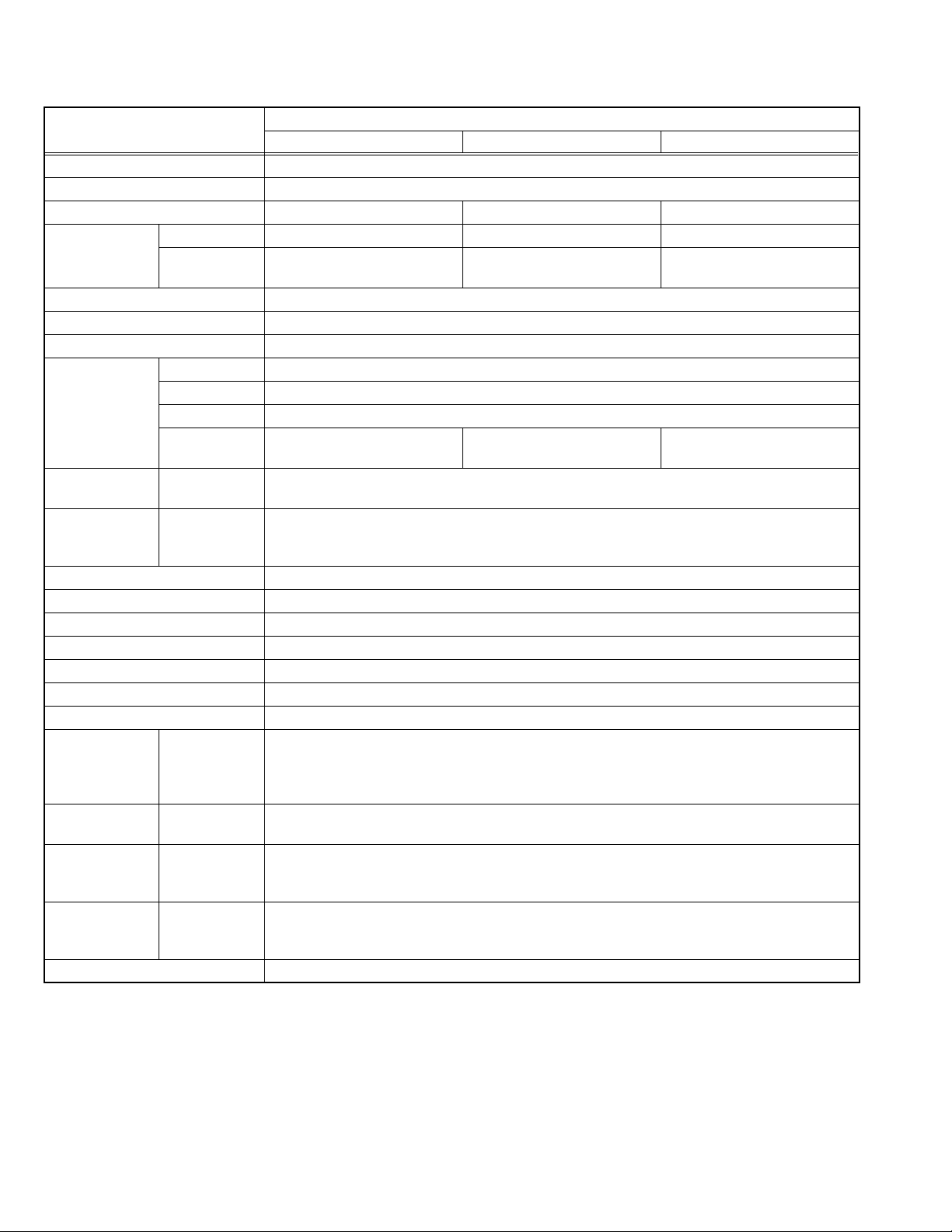
SPECIFICATION
Item
Dimensions ( W × H × D ) 61cm × 45cm × 48cm
Mass 20.5kg
TV RF System B/G, D/K, K1 B/G B/G, L/L'
Colour System TV Mode PAL / SECAM PAL PAL / SECAM
Video Mode PAL / SECAM / NTSC 3.58 /
NTSC 4.43
Sound System MONO
Teletext System 1page
Number of CH memory position 100ch
Receiving
Frequency
Intermediate
Frequency
Colour Sub
Carrier
Frequency
Power Input AC220V ~ AC240V, 50Hz
Power Consumption 85W(Max), 4W(Standby)
Aerial Input Terminal 75Ω unbalanced, coaxial
Picture Tube Visible size : 51cm (Measured diagonally)
High Voltage 25.3kV
Speaker 5.7cm × 16cm oval type × 2
Audio Output 5.5W
Input Video
Output Video
Input Terminal Front Side
Output Terminal Right Side
Remote Control Unit VE-30017763 (RM-C1100), (AA/R06 dry battery × 2)
Design & specifications are subject to change without notice.
VHF Low 46.25MHz ~ 168.25MHz
VHF High 175.25MHz ~ 463.25MHz
UHF 471.25MHz ~ 863.25MHz
CATV BG : S01-S41 & S75-S79
DK : S01-S41
VIF
38.9MHz (B/G, D/K, L) / 33.9MHz (L')
SIF
33.4MHz (5.5MHz:B/G) / 32.9MHz (6.0MHz:D/K) / 32.4MHz (6.5MHz:L) / 40.4MHz (6.5MHz:L')
PAL
4.43MHz
SECAM
S-Video
Audio (MONO)
Audio (MONO)
Rear Side
Rear Side
4.40625MHz / 4.25MHz
NTSC
3.58MHz / 4.43MHz
1V(p-p) 75Ω
Y : 1V(p-p) positive
C : 0.286V(p-p)
500mV(rms) (-4dBs), High impedance (RCA pin jack)
1V(p-p) 75Ω
500mV(rms), Low impedance
F-AV (Video / Audio)
AV-1 (Video / Audio / RGB)
AV-1S (Video / Audio / RGB / S-VIDEO)
Headphone Jack (Mono mini jack Ø3.5mm × 1)
AV-1 (Video / Audio)
AV-1S (Video / Audio)
AV-21KJ1SEF AV-21KJ1SNF AV-21KJ1SPF
PAL / NTSC 3.58 / NTSC 4.43 PAL / SECAM / NTSC 3.58 /
BG : S01-S41 & S75-S79 BG : S01-S41 & S75-S79
Content
NTSC 4.43
L : S01-S41 & S75-S77
1-2 (No.52135)
Page 3

SECTION 1
PRECAUTION
1.1 SAFETY PRECAUTIONS
(1) The design of this product contains special hardware,
many circuits and components specially for safety
purposes. For continued protection, no changes should be
made to the original design unless authorized in writing by
the manufacturer. Replacement parts must be identical to
those used in the original circuits. Service should be
performed by qualified personnel only.
(2) Alterations of the design or circuitry of the products should
not be made. Any design alterations or additions will void
the manufacturer's warranty and will further relieve the
manufacturer of responsibility for personal injury or
property damage resulting therefrom.
(3) Many electrical and mechanical parts in the products have
special safety-related characteristics. These characteristics are often not evident from visual inspection nor can the
protection afforded by them necessarily be obtained by using replacement components rated for higher voltage, wattage, etc. Replacement parts which have these special
safety characteristics are identified in the parts list of Service manual. Electrical components having such fea-
tures are identified by shading on the schematics an d
by ( ) on the parts list in Service manual. The use of
a substitute replacement which does not have the same
safety characteristics as the recommended replacement
part shown in the parts list of Service manual may cause
shock, fire, or other hazards.
(4) Don't short between the LIVE side ground and
ISOLATED (NEUTRAL) side ground or EARTH side
ground when repairing.
Some model's power circuit is partly different in the GND.
The difference of the GND is shown by the LIVE : ( ) side
GND, the ISOLATED (NEUTRAL) : ( ) side GND and
EARTH : ( ) side GND.
Don't short between the LIVE side GND and ISOLATED
(NEUTRAL) side GND or EARTH side GND and never
measure the LIVE side GND and ISOLATED (NEUTRAL)
side GND or EARTH side GND at the same time with a
measuring apparatus (oscilloscope etc.). If above note will
not be kept, a fuse or any parts will be broken.
(5) If any repair has been made to the chassis, it is
recommended that the B1 setting should be checked or
adjusted (See B1 POWER SUPPLY check).
(6) The high voltage applied to the picture tube must conform
with that specified in Service manual. Excessive high
voltage can cause an increase in X-Ray emission, arcing
and possible component damage, therefore operation u nder
excessive high voltage conditions should be kept to a
minimum, or should be prevented. If severe arcing occurs,
remove the AC power immediately and determine the cause
by visual inspection (incorrect installation, cracked or melted
high voltage harness, poor soldering, etc.). To maintain the
proper minimum level of soft X-Ray emission, components
in the high voltage circuitry including the picture tube must
be the exact replacements or alternatives approved by the
manufacturer of the complete product.
(7) Do not check high voltage by d rawing an arc. Use a high
voltage meter or a high voltage probe with a VTVM.
Discharge the picture tube before attempting meter
connection, by connecting a clip lead to the gr ound frame
and connecting the other end of the lead through a 10kΩ
2W resistor to the anode button.
(8) When service is required, obse rve the original lead dress.
Extra precaution should be given to assure correct lead
dress in the high voltage circuit area. Where a short circuit
has occurred, those components that indicate evidence of
overheating should be replaced. Always use the
manufacturer's replacement components.
(9) Isolation Check (Safety for Electrical Shock Hazard)
After re-assembling the product, always perform an
isolation check on the exposed metal parts of the cabinet
(antenna terminals, video/audio input and output terminals,
Control knobs, metal cabinet, screw heads, earphone jack,
control shafts, etc.) to be sure the product is safe to operate
without danger of electrical shock.
a) Dielectric Strength Test
The isolation between the AC primary circuit and all metal
parts exposed to the user, particularly any exposed metal
part having a return path to the chassis should withstand a
voltage of 3000V AC (r.m.s.) for a period of one second. (. .
. . Withstand a voltage of 1100V AC (r.m.s.) to an appliance
rated up to 120V, and 3000V AC (r.m.s.) to an appliance
rated 200V or more, for a period of one second.)
This method of test requires a test equipment not generally
found in the service trade.
b) Leakage Current Chec k
Plug the AC line cord directly into the AC outlet (do not use
a line isolation transformer during this check.). Using a
"Leakage Current Tester", measure the leakage current
from each exposed metal part of the cabinet, particularly
any exposed metal part having a return path to the chassis,
to a known good earth ground (water pipe, etc.). Any
leakage current must not exceed 0.5mA AC (r.m.s.).
However, in tropical area, this must not exceed 0.2mA AC
(r.m.s.).
Alternate Check Method
Plug the AC line cord directly into the AC outlet (do not
use a line isolation transformer during this check.). Use
an AC voltmeter having 1000Ω per volt or more
sensitivity in the following manner. Connect a 1500Ω
10W resistor paralleled by a 0.15µF AC-type capacitor
between an exposed metal part and a known good earth
ground (water pipe, etc.). Measure the AC voltage
across the resistor with the AC voltmeter. Move the
resistor connection to each exposed metal part,
particularly any exposed metal part having a return path
to the chassis, and measure the AC voltage ac ross the
resistor. Now, reverse the plug in the AC outlet and
repeat each measurement. Any voltage measured must
not exceed 0.75V AC (r.m.s.). This corresponds to
0.5mA AC (r.m.s.).
However, in tropical area, this must not exceed 0.3V AC
(r.m.s.). This corresponds to 0.2mA AC (r.m.s.).
AC VOLTMETER
(HAVING 1000 /V,
OR MORE SENSITIVITY)
0.15 F AC-TYPE
PLACE THIS PROBE
1500 10W
GOOD EARTH GROUND
ON EACH EXPOSED
METAL PART
(No.52135)1-3
Page 4
SECTION 2
SPECIFIC SERVICE INSTRUCTIONS
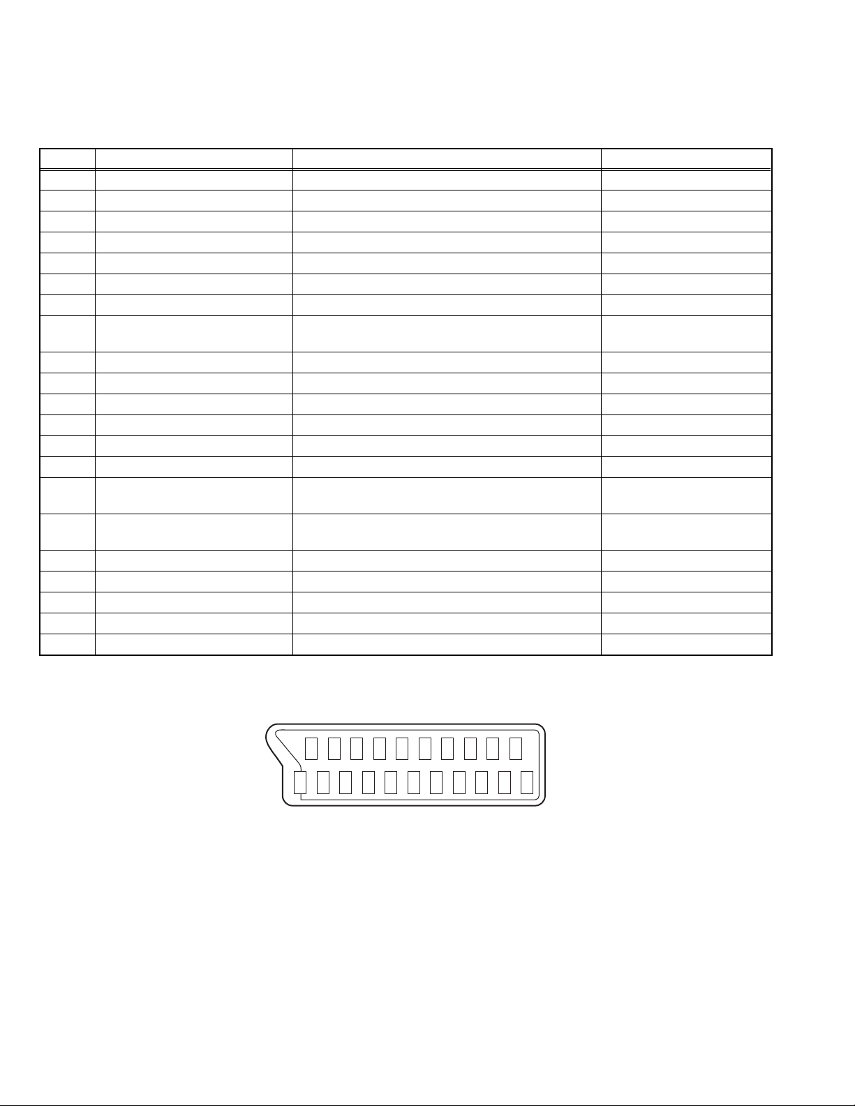
2.1 21-pin Euro connector (SCART) : AV-1 (AV-1S)
Pin No. Signal Designation Matching Value AV-1 (AV-1S)
1 AUDIO R output 500mV(rms) (Nominal), Low impedance Used
2 AUDIO R input 500mV(rms) (Nominal), High impedance Used (R1)
3 AUDIO L output 500mV(rms) (Nominal), Low impedance Used
4 AUDIO GND --- Used
5 GND (B) --- Used
6 AUDIO L input 500mV(rms) (Nominal), High impedance Used (L1)
7 B input 700mV(B-W), 75 Ω Used
8 FUNCTION SW
(SLOW SW)
9 GND (G) --- Used
10 SCL / T-V LINK --- Not used
11 G input 700mV(B-W), 75 Ω Used
12 SDA3 --- Not used
13 GND (R) --- Used
14 GND (YS) --- Used
15 R / C input R : 700mV(B-W), 75 Ω
16 Ys input
(FAST SW)
17 GND (VIDEO output) --- Used
18 GND (VIDEO input) --- Used
19 VIDEO output 1V
20 VIDEO / Y input 1V
21 COMMON GND --- Used
Low : 0V-3V, High : 8V-12V,
High impedance
C : 300mV
Low : 0V-0.4V, 75 Ω
High : 1V-3V, 75 Ω
(Negative sync), 75 Ω Used
(P-P)
(Negative sync), 75 Ω Used
(P-P)
(P-P)
, 75 Ω
Used
Used (R)
Used
(P-P= Peak to Peak, B-W= Blanking to white peak)
[Pin assignment]
20 18 16 14 12 10 8 6 4 2
21 19 17 15 13 11 9 7 5 3 1
1-4 (No.52135)
Page 5
2.2 FEATURES
• It is a remote controlled color television.
• 100 programs from VHF, UHF bands or cable channels can be
preset.
• It can tune cable channels.
• Controlling the TV is very easy by its menu driven system.
• It has an Euroconnector sockets for external device (such as
video recorder, video games, audio set, etc.)
• Front AV Input available.
• Teletext
2.3 MAIN DIFFERENCE LIST
Part Name [/A models] [/B models]
Model name AV-21KJ1SEF/A
AV-21KJ1SNF/A
AV-21KJ1SPF/A
PICTURE TUBE VE-LG320X65 VE-THO13X191
Part Name AV-21KJ1SEF AV-21KJ1SNF AV-21KJ1SPF
MAIN PWB ASSY VE-20121217 [/A]
VE-20129868 [/B]
INSTRUCTION BOOK VE-50036407 VE-50036405 VE-50036406
RATING LABEL VE-20122454 VE-201 22401 VE-20122464
CARTON BOX VE-50036440 VE-50036437 VE-20116664
• It is possible to connect headphone.
• Direct channel access.
• APS (Automatic Programming System).
• All programs can be named.
• Forward or backward automatic tuning.
• Sleep timer.
• Automatic sound mute when no transmission.
• 5 minutes after the broadcasting (closedown), the TV switches
itself automatically to stand-by mode.
AV-21KJ1SEF/B
AV-21KJ1SNF/B
AV-21KJ1SPF/B
VE-20117567 [/A]
VE-20129871 [/B]
VE-20121219 [/A]
VE-20129884 [/B]
(No.52135)1-5
Page 6

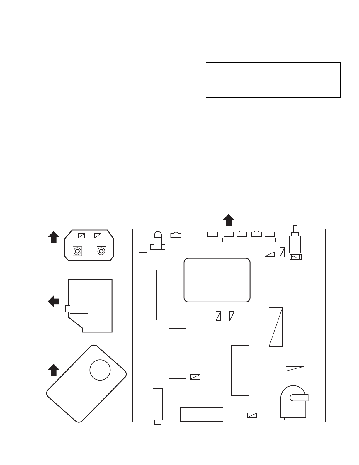
SECTION 3
DISASSEMBLY
3.1 DISASSEMBLY PROCEDURE
3.1.1 REMOVING THE REAR COVER
(1) Unplug the power cord.
(2) Remove the 7 screws [A] as shown in the Fig. 1.
(3) Withdraw the REAR COVER toward you.
3.1.2 REMOVING THE MAIN PWB
• Remove the REAR COVER.
(1) Slightly raise the both sides of the chassis by han d and
withdraw the MAIN PWB backward.
(If necessary, take off the wire clamp, connectors etc.)
3.1.3 REMOVING THE SPEAKER
• Remove the REAR COVER.
(1) Remove the 4 screws [B], and remove speaker as shown
in Fig. 1.
(2) Remove the speaker.
(3) Remove the other side speaker by same procedure.
3.1.4 REMOVING THE FRONT AV PWB
• Remove the REAR COVER.
• Remove the MAIN PWB.
(1) Remove the 2 screws [C] as shown in Fig. 1.
(2) Remove the FRONT AV PWB.
3.1.6 CHECKING THE PW BOARD
• To check the back side of the PW Board.
(1) Pull out the PW Board . (Refer to REMOVING THE MAIN
PWB).
(2) Erect the PW Board vertically so that you can easily check
the back side of the PW Board.
3.1.7 CAUTION
• When erecting the PW Board, be careful so that there will be
no contacting with other PW Board.
• Before turning on power, make sure that the wire connector is
properly connected.
• When conducting a check with power supplied, be sure to
confirm that the CRT EARTH WIRE (BRAIDED ASS'Y) is
connected to the CRT SOCKET PW board.
3.1.8 WIRE CLAMPING AND CABLE TYING
(1) Be sure to clamp the wire.
(2) Never remove the cable tie used for tying the wires togeth-
er.
Should it be inadvertently removed, be sure to tie the wires
with a new cable tie.
3.1.5 REMOVING THE HEADPHONE PWB
• Remove the REAR COVER.
• Remove the MAIN PWB.
(1) Remove the 1 screw [D] as shown in Fig. 1.
(2) Remove the HEADPHONE PWB.
1-6 (No.52135)
Page 7
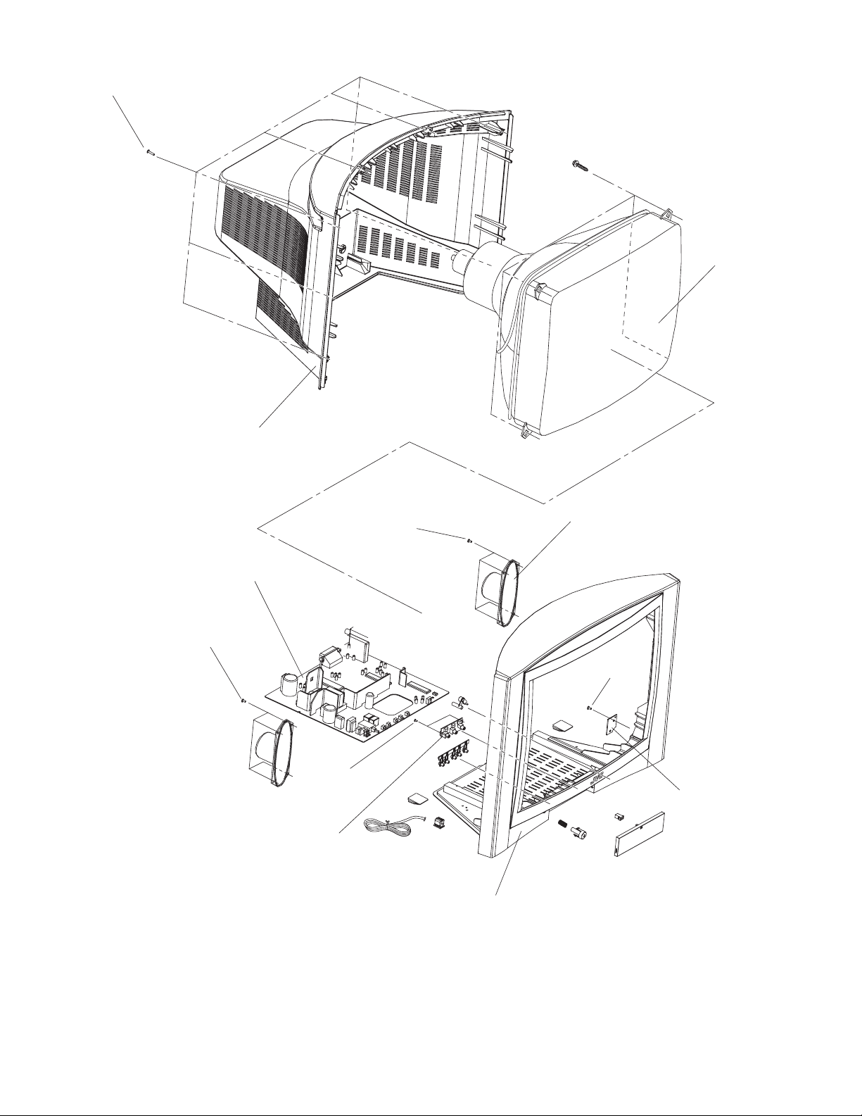
A
(X7)
CRT
REAR COVER
MAIN PWB
(X4)
B
FRONT AV PWB
C
(X2)
B
(X4)
SPEAKER
(X1)
D
HEADPHONE
PWB
FRONT CABINET
Fig.1
(No.52135)1-7
Page 8
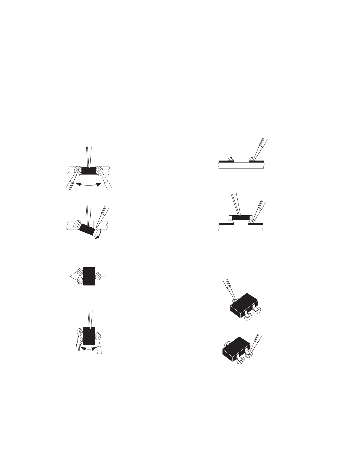
3.2 REPLACEMENT OF CHIP COMPONENT
3.2.1 CAUTIONS
(1) Avoid heating for more than 3 seconds.
(2) Do not rub the electrodes and the resist parts of the pattern.
(3) When removing a chip part, melt the solder adequately.
(4) Do not reuse a chip part after removing it.
3.2.2 SOLDERING IRON
(1) Use a high insulation soldering iron with a thin pointed end of it.
(2) A 30w soldering iron is recommended for ea sily removing parts.
3.2.3 REPLACEMENT STEPS
1. How to remove Chip parts
2. How to install Chip parts
[Resistors, capacitors, etc.]
(1) As shown in the figure, push the part with tweezers and
alternately melt the solder at each end.
(2) Shift with the tweezers and remove the chip part.
[Transistors, diodes, variable resistors, etc.]
(1) Apply extra solder to each lead.
SOLDER
SOLDER
[Resistors, capacitors, etc.]
(1) Apply solder to the pattern as indicated in the figure.
(2) Grasp the chip part with tweezers and place it on the
solder. Then heat and melt the solder at both ends of the
chip part.
[Transistors, diodes, variable resistors, etc.]
(1) Apply solder to the pattern as indicated in the figure.
(2) Grasp the chip part with tweezers and place it on the
solder.
(3) First solder lead A as indicated in the figure.
(2) As shown in the figure, push the part with tweezers and
alternately melt the solder at each lead. Shift and remove
the chip part.
NOTE :
After removing the part, remove remaining solder from the
pattern.
1-8 (No.52135)
A
B
C
(4) Then solder leads B and C.
A
B
C
Page 9
3.3 REPLACEMENT OF MEMORY IC
3.3.1 MEMORY IC
This model use a memory IC. This memory IC stores data for proper operation of the video and deflection circuits.
When replacing, be sure to use an IC containing this (initial value) data.
3.3.2 PROCEDURE FOR REPLACING MEMORY IC
1. Power off
Switch the power off and unplug the power cord from the
outlet.
2. Replace IC.
Be sure to use memory IC written with the initial data values.
3. Power on
Plug the power cord into the outlet and switch the power on.
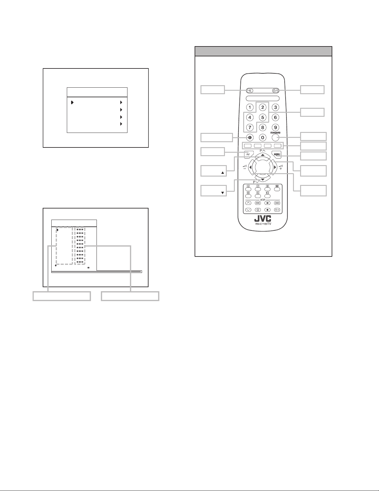
4. SERVICE MENU setting
(1) Press [MENU] key and, while the displayed MENU
screen, press [4], [7], [2], [5] key on the remote control
unit or press [MUTING] key and [INFORMATION] key at
the simultaneously.
(2) The SERVICE MENU screen of Fig. 1 will be displayed.
(3) Verify what to set in the SERVICE MENU, and set
whatever is necessary (Fig.1). Refer to the SERVICE
ADJUSTMENT for setting.
(4) Press the [STANDARD] key to exit SERVICE MENU.
5. Receive channel setting
Refer to the OPERATING INSTRUCTIONS (USER'S GUIDE)
and set the receive channels (Channels Preset) as described.
MUTING
SERVICE MENU
AK30-JVC ***
OSD
IF1
IF2
IF3
IF4
AGC
VLIN
VS1A
VS1B
VP1
: 1 1 AVL
Fig.1
SERVICE MENU SELECT KEY
POWER
6. User settings
Check the user setting items according to after page.
Where these do not agree, refer to the OPERATING
INSTRUCTIONS (USER'S GUIDE) and set the items as
described.
INFORMATION
AV
ITEM
SELECT ( )
ITEM
SELECT ( )
Fig.2
NUMBER
STANDARD
COLOUR
MENU
VAL UE
SELECT (+)
VAL UE
SELECT (-)
(No.52135)1-9
Page 10
3.4 SETTING OF THE LAST MEMORY FOR SHIPMENT
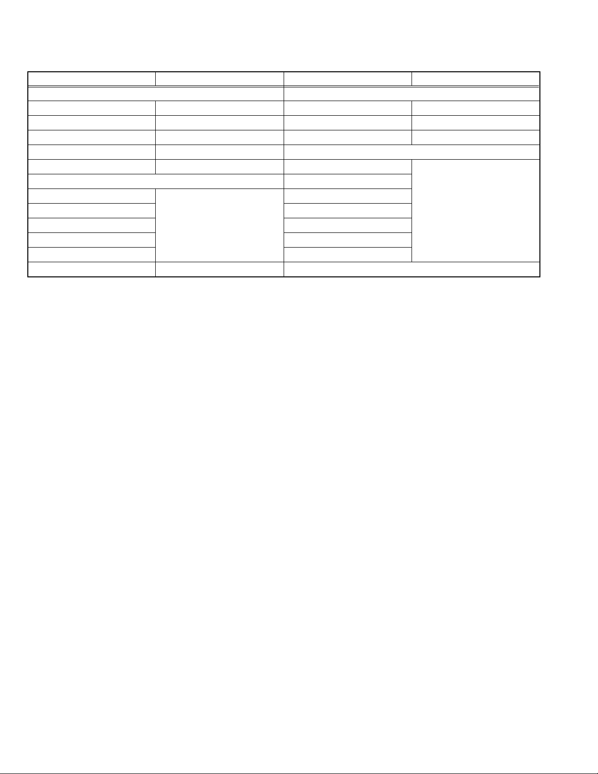
3.4.1 USER SETTING VALUES
Setting Item Setting Value Setting Item Setting Value
SOUND MENU FEATURE MENU
BALANCE CENTER SLEEP TIMER OFF
BASS CENTER CHILD LOCK OFF
TREBLE CENTER LANGUAGE ENGLISH
MODE MONO INSTALL
EFFECT OFF PROGRAMM E Refer to the INSTRUCTION
PICTURE MENU BAND
BRIGHTNESS These adjust are automatically
CONTRAST STANDARD
COLOUR SEARCH
SHARPNESS FINE TUNING
HUE(only NTSC) STORE
MODE AUTO
3.4.2 SETTING APS BIT IN SERVICE MENU
(1) Enter service menu in TV mode by pressing "INFORMATION" and "MUTING"keys simultaneously. Service Menu will appear.
(2) Select TX1(TELETEXT OPTION) by pressing Up/Down keys on remote control unit.
(3) Press the 7 key on remote control unit to set APS bit. (After this, bit 7 of TX1 will be "1")
(4) Press STANDARD key on remote control unit to exit service mode.
NOTE :
DO NOT TURN OFF THE TV BY USING POWER BUTTON ON THE FRONT PANEL.
restored when APS bit in
Service menu is set.
The procedure for setting APS
bit is described below.
CHANNEL
BOOK.
1-10 (No.52135)
Page 11
SECTION 4
ADJUSTMENT
4.1 ADJUSTMENT PREPARATION
(1) You can make the necessary adjustments for this unit with
either the Remote Control Unit or with the adjustment tools
and parts as given below.
(2) Adjustment with the Remote Control Unit i s made on the
basis of the initial setting values, however, the new setting
values which set the screen to its optimum condition may
differ from the initial settings.
(3) Make sure that AC power is turned on correctly.
(4) Turn on the power for set and test equipment before use,
and start the adjustment procedures after waiting at least
30 minutes.
(5) Unless otherwise specified, prepare the most suitab le re-
ception or input signal for adjustment.
(6) Never touch any adjustment parts w hich are not specified
in the list for this adjustment - variable resistors, transform-
ers, condensers, etc.
(7) Presetting before adjustment.
Unless otherwise specified in the adjustment instructions,
preset the following functions with the remote control unit:
BRIGHTNESS CENTER
CONTRAST
COLOUR
SHARPNESS
4.2 ADJUSTMENT EQUIPMENT
(1) DC voltmeter (or digital voltmeter)
(2) Signal generator (Pattern generator)
[PAL / SECAM / NTSC]
(3) Remote control unit
4.3 ADJUSTMENT ITEM
• FOCUS ADJUSTMENT
• SCREEN ADJUSTMENT
• OSD HORIZONTAL POSITION ADJUSTMENT
• IF ADJUSTMENT
• AGC AUTOMATICALLY ADJUSTMENT
• DEFLECTION CIRCUIT ADJUSTMENT
• WHITE BALANCE ADJUSTMENT
4.4 ADJUSTMENT LOCATIONS
FRONT
FRONT AV PWB
SIDE
HP
HEADPHONE PWB
TOP
IC500
EEP ROM
IC501
MICOM
TUNER
LED
REMOCON
RECEIVER
IC403
PL405
MENU
FRONT
CH. / PROG.
PL302
IC700
(+) (-)(+) (-)
VOL.
DEG
COIL
POWER
CORD
HVT
MAIN
SW
FUSE
12.5A
MAIN PWB
HV
FBT
SCART
CRT SOCKET PWB MAIN PWB
PL602
UPPER:FOCOUS
LOWER:SCREEN
(No.52135)1-11
Page 12
4.5 BASIC OPERATION OF SERVICE MENU
4.5.1 HOW TO ENTER SERVICE MENU
(1) Press the MENU key.
(2) MENU screen of (fig.1) will be displayed.
MENU SCREEN
SERVICE MENU SELECT KEY
MENU
PICTURE
FEATURE
INSTALL.
PROGRAM.
Fig.1
(3) While the MENU screen is displayed , press the [4], [7], [2],
[5] key or [INFORMATION] key and [MUTING] key
simultaneously.
(4) The SERVICE MENU screen of (Fig.2) will be displayed.
SERVICE MENU SCREEN
AK30-JVC ***
OSD
IF1
IF2
IF3
IF4
AGC
VLIN
VS1A
VS1B
VP1
: 1 1 AVL
MUTING
INFORMATION
AV
ITEM
SELECT ( )
ITEM
SELECT ( )
Fig.3
POWER
NUMBER
STANDARD
COLOUR
MENU
VAL UE
SELECT (+)
VAL UE
SELECT (-)
ADJUSTMENT ITEM SETTING VALUE
Fig.2
4.5.2 SELECTION OF ADJUSTMENT ITEMS
(1) Enter the SERVICE MENU
(2) Press the [/] key and select the ADJUSTMENT ITEM.
(3) Press the [/] key and set the SETTING VALUE.
4.5.3 HOW TO EXIT SERVICE MODE
(1) Press the [STANDARD] Key on REMOTE CONTROL
UNIT.
1-12 (No.52135)
Page 13

4.5.4 ADJUSTMENT ITEM
ADJUSTMENT ITEM DESCRIPTION
OSD OSD Horizontal Position
IF1 IF Coarse Adjust
IF2 IF Fine Adjust
IF3 IF Coarse Adjust for L-Prime
IF4 IF Fine Adjust for L-Prime
AGC Automatic Gain Control
VLIN Vertical Linearity
VS1A Vertical Size for 50 Hz / 4:3
VS1B Vertical Size for 50 Hz / 16:9
VP1 Vertical Position for 50 Hz
HP1 Horizontal Position for 50 H
VS2A Vertical Size for 60 Hz / 4:3
VS2B Vertical Size for 60 Hz / 16:9
VP2 Vertical Position for 60 Hz
HP2 Horizontal Position for 60 Hz
RGBH RGB Horizontal Shift Offset
WR White Point Adjust for RED
WG White Point Adjust for GREEN
WB White Point Adjust for BLUE
BR Bias for RED
BG Bias for GREEN
APR APR Threshold
BRI Brightness
CON Contrast
COL Colour
SHA Sharpness
HUE Hue
VOL Volume
WR-R White Point Adjust for RED (RGB mode)
WG-R White Point Adjust for GREEN (RGB mode)
WB-R White Point Adjust for BLUE (RGB mode)
FMP1 FM Prescaler when AVL is OFF
NIP1 NICAM Prescaler when AVL is OFF
SCP1 SCART Prescaler when AVL is OFF
FMP2 FM Prescaler when AVL is ON
NIP2 NICAM Prescaler when AVL is ON
SCP2 SCART Prescaler when AVL is ON
F1H High Byte of crossover frequency for VHF1-VHF3
F1L Low Byte of crossover frequency for VHF1-VHF3
F2H High Byte of crossover frequency for VHF3-UHF
F2L Low Byte of crossover frequency for VHF3-UHF
BS1 Band Switch Byte for VHF1
BS2 Band Switch Byte for VHF3
BS3 Band Switch Byte for UHF
CB Control Byte
OP1 Peripheral Options
OP2 Recep tion Standard Options
OP3 Video Options
OP4 TV Features
OP5 Channel Tables
TX1 Teletext Options
(No.52135)1-13
Page 14
4.6 ADJUSTMENT PROCEDURE
r
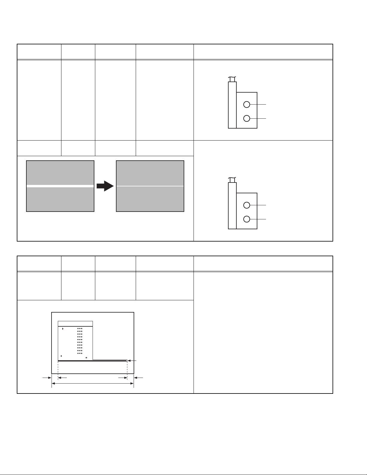
4.6.1 FOCUS / SCREEN ADJUSTMENT
Item
FOCUS
adjustment
Measuring
instrument
Signal
generator
Test point Adjustment part Description
Remote
control unit
FOCUS VR
[On the FBT]
(1) Receive a PAL cross-hatch signal.
(2) Adjust FOCUS VR on the FBT as thin as possible.
FOCUS VR
SCREEN VR
FBT
SCREEN
adjustment
Remote
control unit
4.6.2 OSD ADJUSTMENT
Item
HORIZONTAL
POSITION OF
Measuring
instrument
Remote
control unit
OSD
adjustment
SERVICE MENU SCREEN
SCREEN VR
[On the FBT]
(1) Enter the SERVICE MENU.
(2) Press the [YELLOW] key to disable vertical scan.
(3) Adjust SCREEN VR. on the FBT as thin as possible.
(4) Press [YELLOW] key again to enable vertical scan.
(5) Press [STANDARD] key to leave service menu.
FOCUS VR
SCREEN VR
FBT
Test point Adjustment part Description
OSD (1) Enter the SERVICE MENU.
(2) Select OSD with the [/] key.
(3) Adjust the OSD horizontal position with the [/]
key, which shifts the reference bar on the bottom of
the SERVICE MENU horizontally, so that the OSD is
positioned on the screen center. (X=X')
1-14 (No.52135)
AK30-JVC ***
OSD
IF1
IF2
IF3
IF4
AGC
VLIN
VS1A
VS1B
VP1
: 1 1 AVL
XX'
Screen size
Reference ba
Page 15
4.6.3 IF ADJUSTMENT
Item
Measuring
instrument
Test point Adjustment part Description
IF adjustment Remote
control unit
4.6.4 AGC AUTOMATICALLY ADJUSTMENT
Item
AGC
AUTOMATICALLY
Measuring
instrument
Remote
control unit
Test point Adjustment part Description
adjustment
IF 1
IF 2
IF 3
IF 4
(1) Receive a PAL colour bar pattern.
(2) Enter the SERVICE MENU.
(3) Select IF 1 with the [/] key
(4) Press [BLUE] key during IF 1 is highlighted, IF 1 and
IF 2 values are adjusted automatically by software.
(5) If the standard is L-p rime, IF 3 and IF 4 values are
adjustment automatically when [BLUE] key is
pressed during IF 1 is highlighted.
AGC (1) Enter the SERVICE MENU.
(2) Receive a 60dBmV RF signal level.
(3) Select AGC with the [/] key.
(4) Press [BLUE] key on the remote control unit.
(5) Then the adjustment will be done automatically by
software.
(6) See the AGC indica tor on SERVICE MENU, it must
be "1".
(7) Check that picture is normal at 90dBmV signal level.
AK30-JVC ***
OSD
IF1
IF2
IF3
IF4
AGC
VLIN
VS1A
VS1B
VP1
: 1 1 AVL
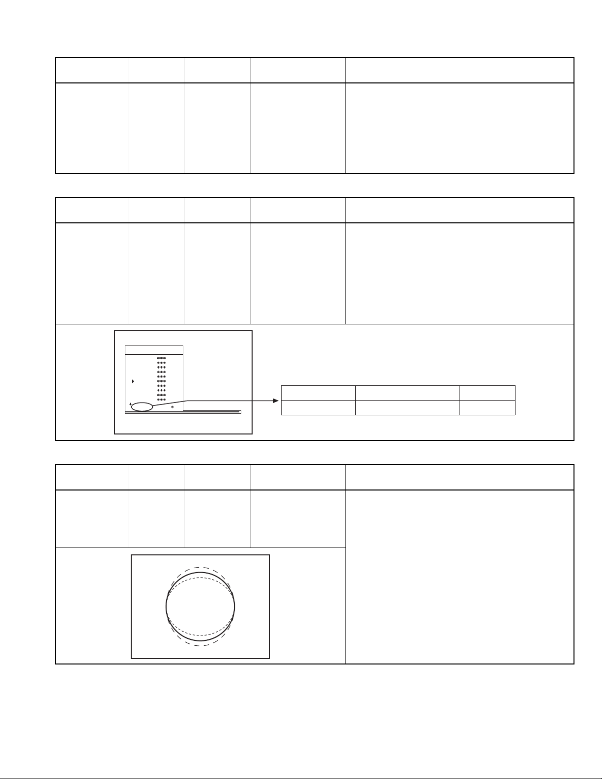
4.6.5 DEFLECTION CIRCUIT ADJUSTMENT
Item
VERTICAL
LINEARITY
Measuring
instrument
Signal
generator
Test point Adjustment part Description
adjustment
Remote
control unit
IF INDICATOR AGC INDICATOR NONE
: 1 1
VLIN (1) Receive a PAL B/G circle pattern.
(2) Enter the SERVICE MENU.
(3) Select VLIN with the [/] key.
(4) Adjust VLIN with the [/] key until circle as round
as possible.
(No.52135)1-15
Page 16
Item
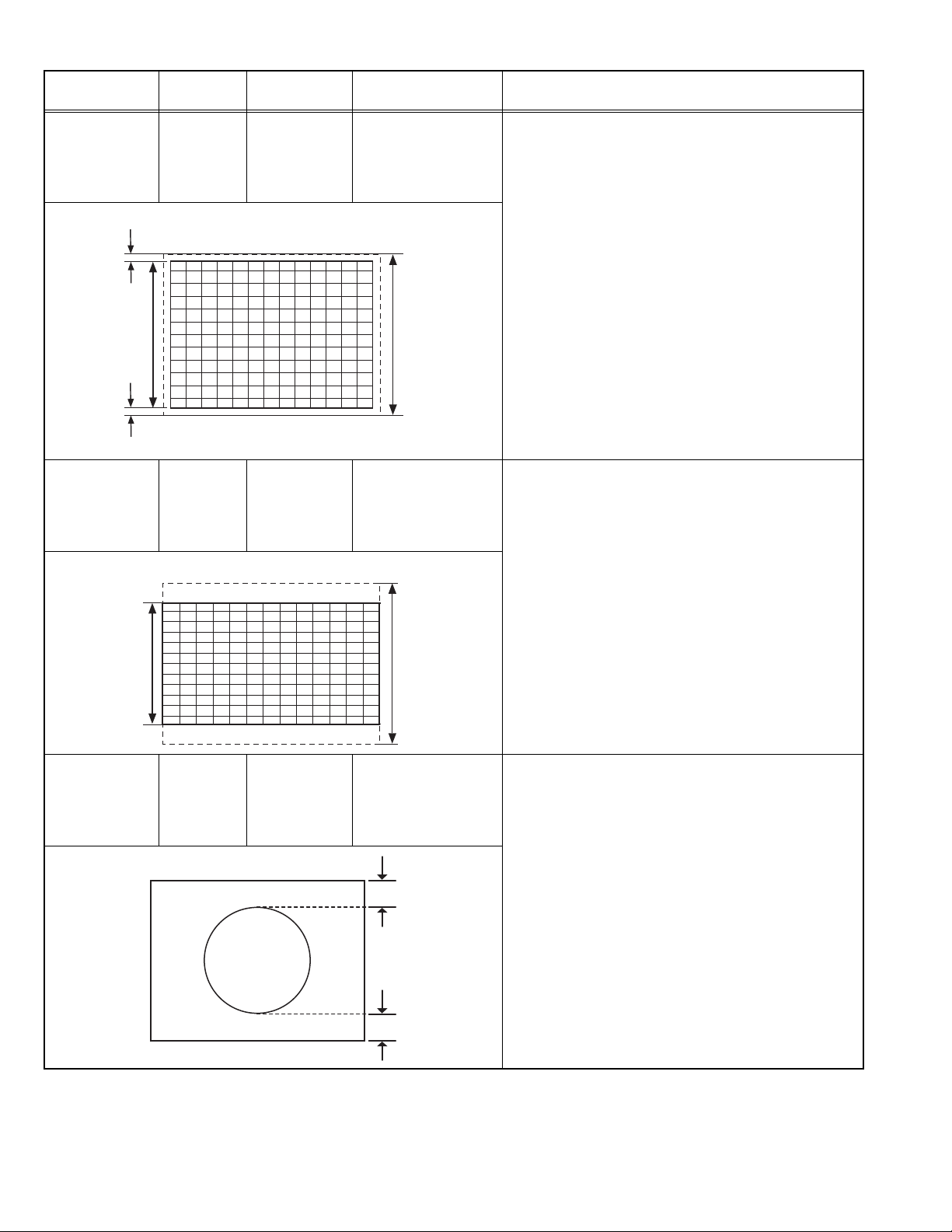
VERTICAL SIZE
adjustment
(50Hz, 4:3)
Very close
Measuring
instrument
Signal
generator
Remote
control unit
Test point Adjustment part Description
VS1A (1) Receive a PAL B/G cross-hatch pattern of vertical
frequency 50Hz.
(2) Enter the SERVICE MENU.
(3) Select VS1A (Vertical size) with the [/] key.
(4) Adjust VS1A with the [/] key until the horizontal
black lines on both the upper and lower horizontal
sides of picture size and nearly about to disappear.
(5) Check and readjust VS1A item if the adjustment
becomes improper after some other geometric
adjustments are done.
Screen
size
Very close
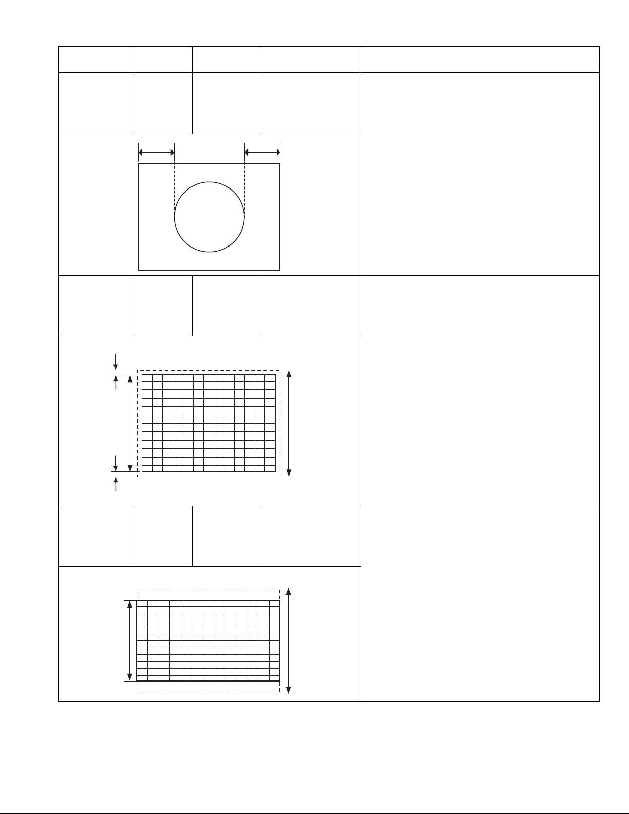
VERTICAL SIZE
adjustment
(50Hz, 16:9)
16:9
format
Screen
size
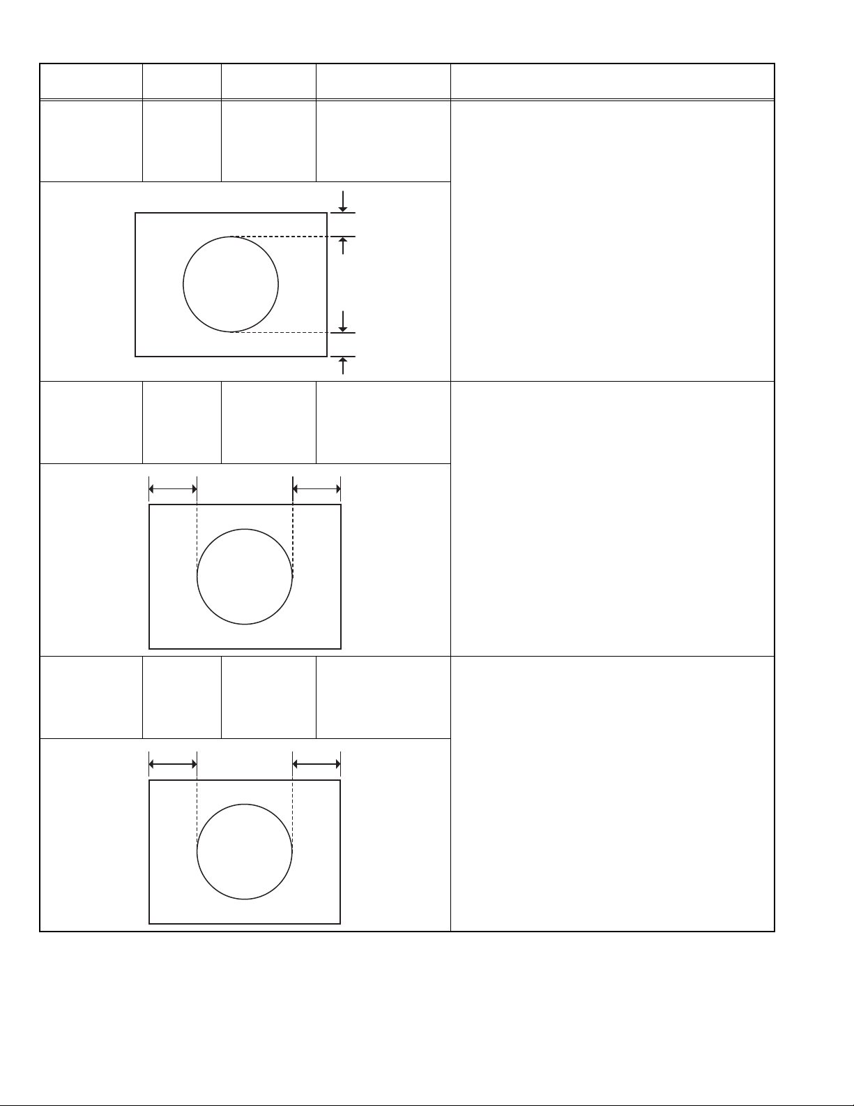
VERTICAL
POSITION
adjustment
(50Hz)
Signal
generator
Remote
control unit
Signal
generator
Remote
control unit
16:9 SCREEN
Picture
size
100%
VS1B (1) Receive a PAL B/G cross-hatch pattern of vertical
frequency 50Hz.
(2) Enter the SERVICE MENU.
(3) Press the [GREEN] to switch to 16:9 screen mode.
(4) Select VS1B (Vertical size) with the [/] key.
(5) Adjust VS1B with the [/] key until the screen
become 16:9 format.
(6) Check and readjust VS1B item if the adjustment
becomes improper after some other geometric
adjustments are done.
Picture
size
100%
VP1 (1) Receive a PAL B/G circle pattern signal of vertical
frequency 50Hz.
(2) Enter the SERVICE MENU.
(3) Select VP1 (Vertical position) with the [/] key.
(4) Adjust VP1 with the [/] key until the circle pattern
is vertically centered. (A=B)
(5) Check and readjust VP1 item if the adjustment
A
becomes improper after some other geometric
adjustments are done.
1-16 (No.52135)
B
Page 17
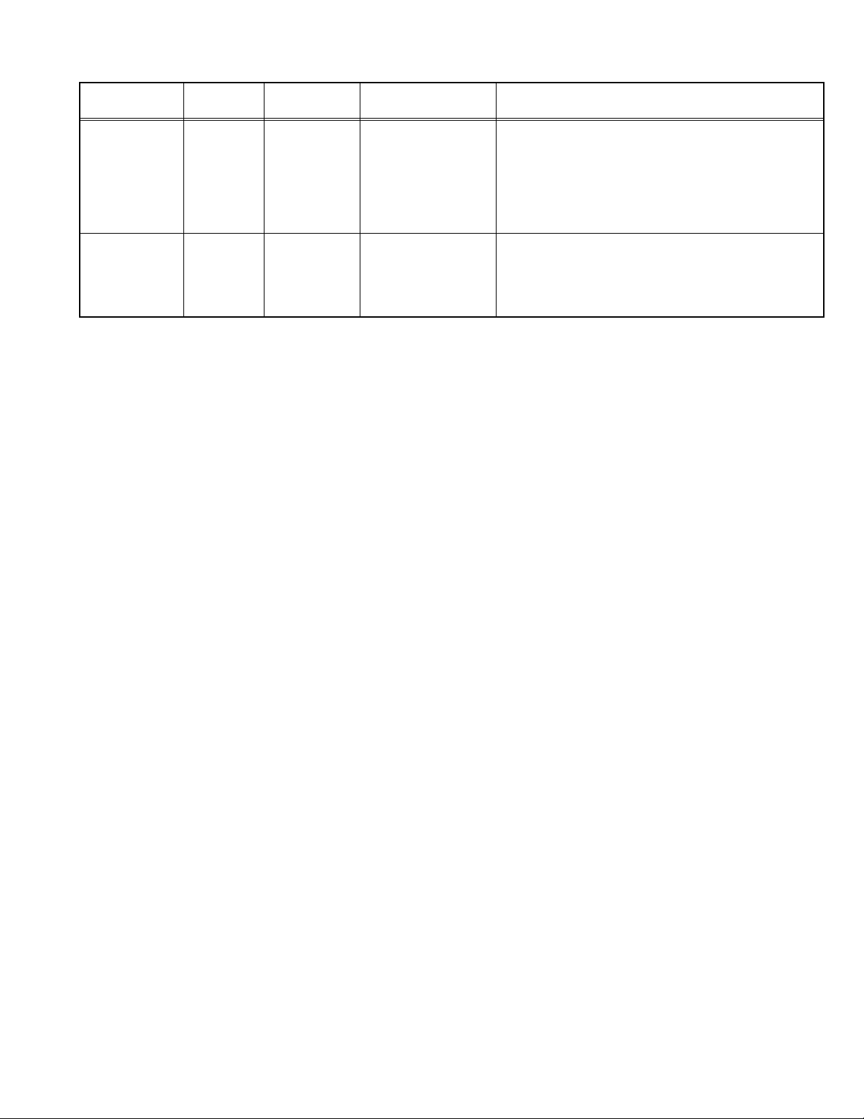
Item
HORIZONTAL
POSITION
adjustment
(50Hz)
Measuring
instrument
Signal
Test point Adjustment part Description
HP1 (1) Re ceive a PAL B/G circle pattern signal of vertical
generator
Remote
control unit
CD
frequency 50Hz.
(2) Enter the SERVICE MENU.
(3) Select HP1 (Horizontal position) with the [/] key.
(4) Adjust HP1 with the [/] key until the circle pattern
is horizontally centered. (C=D)
(5) Check and readjust HP1 item if the adjustment
becomes improper after some other geometric
adjustments are done.
VERTICAL SIZE
adjustment
(60Hz, 4:3)
Very close
Screen
size
Very close
VERTICAL SIZE
adjustment
(60Hz, 16:9)
16:9
format
Screen
size
Signal
generator
Remote
control unit
Signal
generator
Remote
control unit
16:9 SCREEN
VS2A (1) Receive a PAL B/G cross-hatch pattern of vertical
frequency 60Hz.
(2) Enter the SERVICE MENU.
(3) Select VS2A with the [/] key.
(4) Adjust VS2A with the [/] key until the horizontal
black lines on both the upper and lower part of the
pattern become very close to the upper anr lower
horizontal sides of picture size and nearly about to
disappear.
(5) Check and readjust VS2A item if the adjustment
becomes improper after some other geometric
Picture
size
100%
adjustments are done.
VS2B (1) Receive a PAL B/G cross-hatch pattern of vertical
frequency 60Hz.
(2) Enter the SERVICE MENU.
(3) Select VS2B with the [/] key.
(4) Press [GREEN] key to switch to 16:9 screen mode.
(5) Adjust VS2B with the [/] key until the screen
become 16:9 format.
(6) Check and readjust VS2B item if the adjustment
becomes improper after some other geometric
adjustments are done.
Picture
size
100%
(No.52135)1-17
Page 18
Item
VERTICAL
POSITION
adjustment
(60Hz)
Measuring
instrument
Signal
generator
Remote
control unit
Test point Adjustment part Description
VP2 (1) Receive a PAL B/G circle pattern signal of vertical
frequency 50Hz.
(2) Enter the SERVICE MENU.
(3) Select VP2 (Vertical position) with the [/] key.
(4) Adjust VP2 with the [/] key until the circle pattern
is vertically centered. (A=B)
(5) Check and readjust VP2 item if the adjustment
A
becomes improper after some other geometric
adjustments are done.
B
HORIZONTAL
POSITION
adjustment
(60Hz)
RGB MODE
HORIZONTAL
SHIFT OFFSET
adjustment
Signal
generator
Remote
control unit
HP2 (1) Receive a PAL B/G circle pattern signal of vertical
CD
Signal
generator
Remote
control unit
RGBH (1) Input R/G/B circle pattern signal via video input
EF
frequency 50Hz.
(2) Enter the SERVICE MENU.
(3) Select HPOS (Horizontal position) with the [/]
key.
(4) Adjust HP2 with the [/] key until the circle pattern
is horizontally centered. (C=D)
(5) Check and readjust HP2 item if the adjustment
becomes improper after some other geometric
adjustments are done.
terminal.
(2) Press [AV] key on the remote contro l unit, force the
TV to RGB mode.
(3) Enter the SERVICE MENU.
(4) Select RGBH with the [/] key.
(5) Adjust RGBH with the [/] key until the circle
pattern is horizontally centered. (E=F)
(6) Check and readjust RGBH item if the adjustment
becomes improper after some other geometric
adjustments are done.
1-18 (No.52135)
Page 19
4.6.6 WHITE BALANCE ADJUSTMENT
Item
WHITE
BALANCE
adjustment
(Low light)
WHITE
BALANCE
adjustment
(High light)
Measuring
instrument
Signal
generator
Remote
control unit
Signal
generator
Remote
control unit
Test point Adjustment part Description
WR
WG
WB
BR
BG
(1) Receive a black & white signal (colour off).
(2) Enter the SERVICE MENU.
(3) Select WR / WG / WB with the [/] key
respectively.
(4) Adjust WR / WG / WB with the [/] key,
respectively, until the white part turns to pure white
without any other colour.
(1) Receive a black & white signal (colour off).
(2) Enter the SERVICE MENU.
(3) Select BR / BG with the [/] key respectively.
(4) Adjust BR / BG with the [/] key, respectively until
the white part of screen make white colour.
(No.52135)1-19
Page 20

SECTION 5
TROUBLESHOOTING
This service manual does not describe TROUBLESHOOTING.
1-20 (No.52135)
Page 21

VICTOR COMPANY OF JAPAN, LIMITED
AV & MULTIMEDIA COMPANY VIDEO DISPLAY CATEGORY 12, 3-chome, Moriya-cho, kanagawa-ku, Yokohama, kanagawa-prefecture, 221-8528, Japan
(No.52135)
Printed in Japan
WPC
Page 22

AV-21KJ1SEF
ENGLISH
POLSKI
ÈESKY
MAGYAR
ÁÚËÃAPCKÈ
ROMANIAN
COLOUR TELEVISION
KOLOROWY ODBIORNIK TELEWIZYJNY
BAREVNY TELEVIZOR
SZÍNES TELEVÍZIÓ
ÖBETEH TEËEBÈÇOP
TELEVIZOR COLOR
INSTRUCTIONS
INSTRUKCJA OBSLUGI
PØ ÍRUÈKA K OBSLUZE
HASZNÁLATI UTASÍTÁSA
PÚKOBOÄCTBO ÇA PAÁOTA
INSTRUCÞIUNI
Page 23

Contents
Safety Precautions
Safety Precautions ................................................... 1
Remote Control Buttons .......................................... 2
Control Panel Buttons .............................................. 3
Antenna Connections ...............................................3
Preparation ................................................................ 4
Features .......................................................................... 4
Before Switching on your TV .................................. 4
Power connection............................................................. 4
Aerial Connections ........................................................... 4
How to connect the external equipments .......................... 4
Inserting batteries in the remote control handset .............. 4
Switching the TV ON/OFF ........................................4
To switch the TV on.......................................................... 4
To switch the TV off .......................................................... 4
Initial Settings ...........................................................4
Operating with the onset buttons ...................................... 5
Operating with Remote Control ......................................... 5
Menu System .............................................................5
Picture Menu ................................................................... 5
Feature Menu ................................................................... 6
Install. Menu .................................................................... 7
Program. (Programming) Menu ........................................ 7
Other Features.......................................................... 8
Sound Mute ..................................................................... 8
Information on Screen ...................................................... 8
To Display the Time.......................................................... 8
Standard .......................................................................... 8
VCR Control Buttons ........................................................ 8
Teletext...................................................................... 9
To operate Teletext ........................................................... 9
To select a page of Teletext.............................................. 9
To Select Index Page ....................................................... 9
Searching for a teletext page while watching TV ............... 9
To Select Double Height Text ........................................... 9
To Reveal concealed Information .................................... 9
To Stop Automatic Page Change ...................................... 9
To Select a Subcode Page ............................................... 9
To exit Teletext ................................................................. 9
Connect the External Equipments ........................ 10
Via the Euroconnector..................................................... 11
AV-1 S Mode ................................................................... 11
Via the RCA jacks ........................................................... 11
Via the ANT (aerial) socket .............................................. 11
TV and Video Recoder (VCR) .......................................... 11
NTSC Playback .............................................................. 11
Connecting Headphones ................................................. 11
Tips........................................................................... 11
Specifications ..........................................................12
1. Power Source
The receiver should be operated only from a 220-240V AC,
50 Hz. outlet. Ensure you select the correct voltage setting
for your convenience.
2. Power Cord
The power supply cord should be placed so that they are not
likely to be walked on or pinched by items placed upon them
or against them. Pay particular attention to cord where they
enter the plug, power outlet, and the point where they exit
from the receiver.
3. Moisture and Water
Do not use this equipment in a humid and damp place (avoid
the bathroom, the sink in the kitchen, and near the washing
machine). Do not expose this equipment to rain or water and
do not place objects filled with liquids on it as this may be
dangerous.
4. Cleaning
Before cleaning, unplug the receiver from the main supply
outlet. Do not use liquid or aerosol cleaners. Use with soft
and dry cloth.
5. Ventilation
The slots and openings on the receiver are intended for ventilation and to ensure reliable operation. To prevent overheating,
these openings must not be blocked or covered in anyway.
6. Lightning
In case of storm and lightning or when going on holiday, disconnect the power cord from the wall outlet.
7. Replacement Part
When replacement parts are required, be sure the service
technician has used replacement parts which are specified
by the manufacturer or have the same specifications as the
original one. Unauthorized substitutions may result in fire,
electrical shock, or other hazards.
8. Servicing
Please refer all servicing to qualified personnel. Do not remove cover as this may result in electric shock.
9. Flame sources
Do not place naked flame sources on the apparatus.
10. Stand-By
Do not leave your TV stand-by or operating condition when you
leave your house.
Warning!
Any intervention contrary to regulations, in particular, any
modification of high voltage or a replacement of the picture
tube may lead to an increased concentration of x-rays. Any
television modified in this way no longer complies with license
and must not be operated.
Instructions for waste disposal:
Packaging and packaging aids are recyclable and should
principally be recycled. Packaging materials, such as foil
bag, must be kept away from children.
ENGLISH - 1 -
Page 24
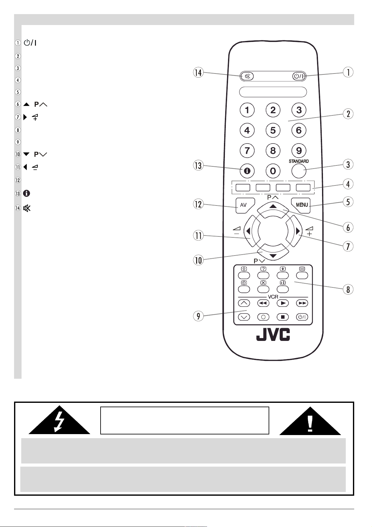
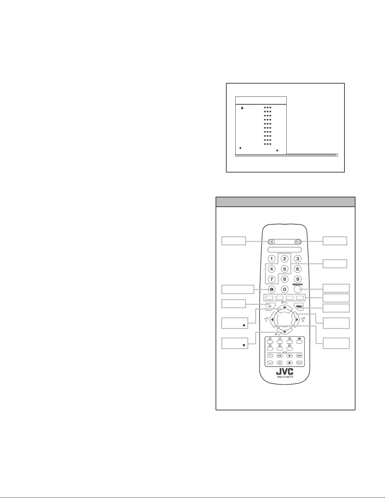
Remote Control Buttons
= Stand By / Power
0 - 9 = Direct Program
Standard Button (PICTURE default settings)
Colour Buttons
MENU = Menu Button
( ) = Cursor Up / Programme Up
( ) = Cursor Right / Volume +
Teletext Control Buttons
VCR Control Buttons
( ) = Cursor Down / Programme Down
( ) = Cursor Left / Volume -
AV = AV Button
= Information Button
= Mute
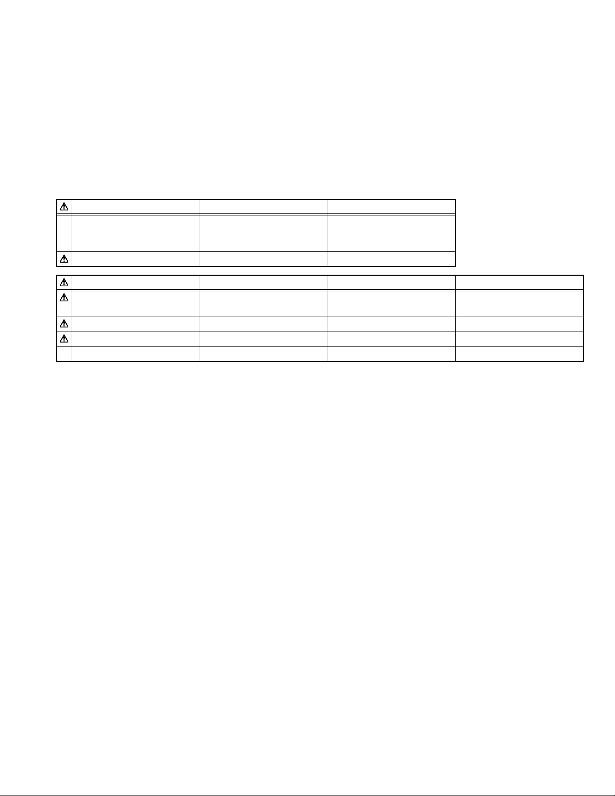
CAUTION
RISK OF ELECTRIC SHOCK
The lightning flash with arrowhead symbol, within an equilateral triangle, is intended to alert the user to the presence of
uninsulated "dangerous voltage" within the product's enclosure that may be of sufficient magnitude to constitute a risk
of electric shock of persons.
The exclamation point within an equilateral triangle is intended to alert the user to the presence of important operating
and maintenance (servicing) instructions in the literature accompanying the appliance.
ENGLISH - 2 -
Page 25
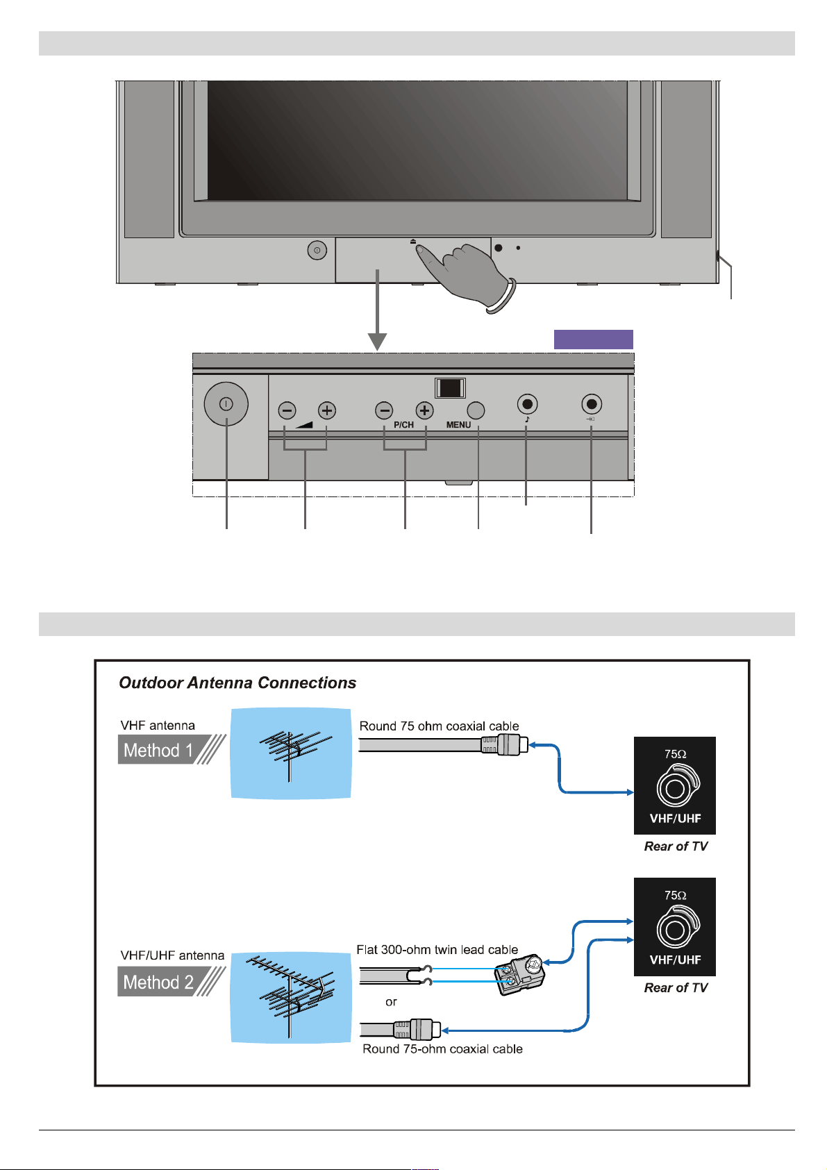
Control Panel Buttons
+HDGSKRQH
)5217$9
3RZHU 0HQX
9ROXPH
3URJUDP
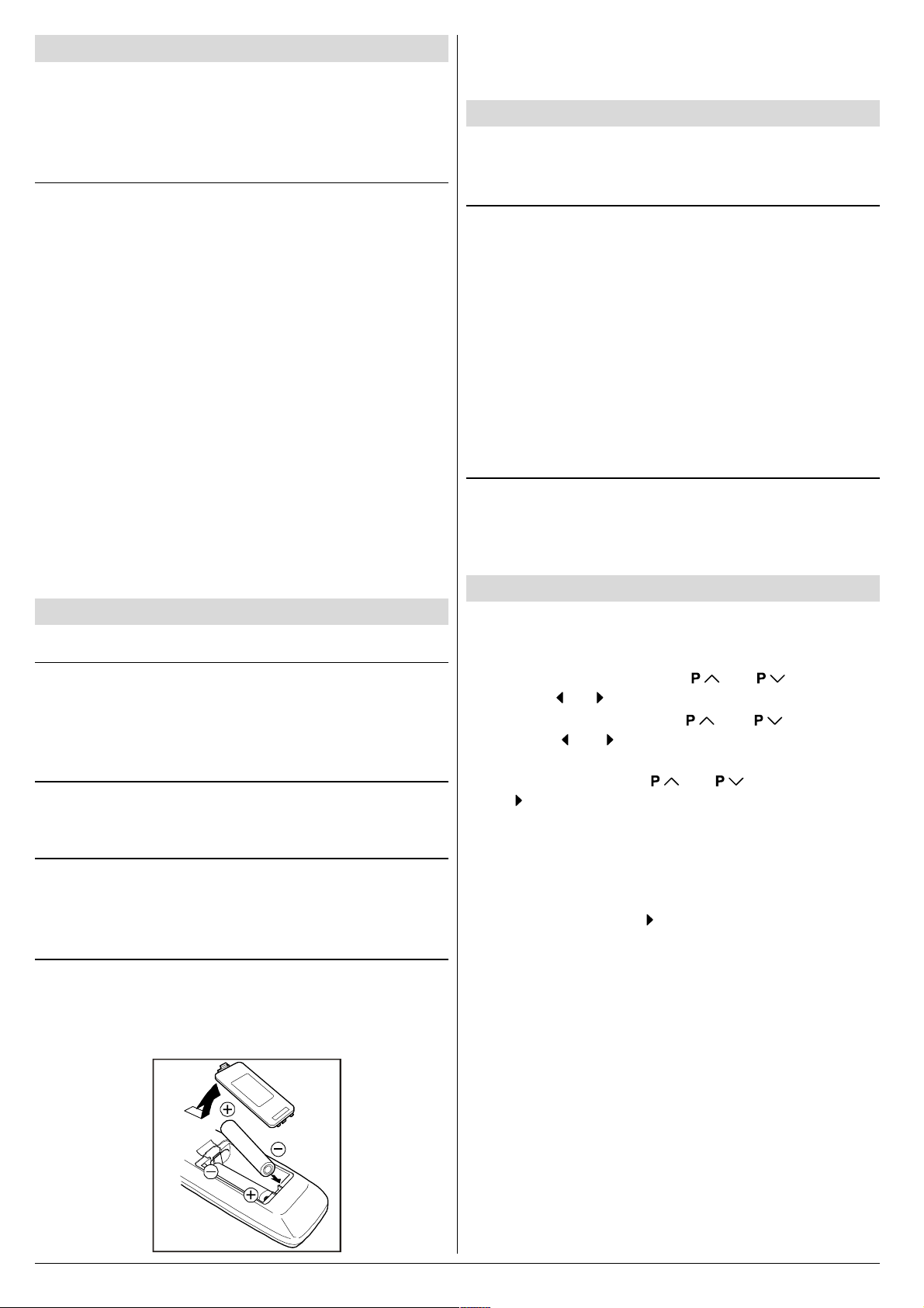
Antenna Connections
$XGLR,QSXW
7HUP L QD O
9LGHR,QSXW
7HUPLQD O
ENGLISH - 3 -
Page 26
Preparation
Place TV on a solid surface.
For ventilation, leave a space of at least 10 cm free all around
the set. To prevent any fault and unsafe situations, please do
not place any objects on top of the set.
Features
It is a remote controlled colour television.
100 programmes from VHF, UHF bands or cable channels
can be preset.
It can tune cable channels.
Controlling the TV is very easy by its menu driven system.
It has an Euroconnector socket for external devices (such
as video recorder, video games, audio set, etc.)
Front AV Input available.
Teletext.
It is possible to connect headphone.
Direct channel access.
APS (Automatic Programming System).
All programmes can be named.
Forward or backward automatic tuning.
Sleep timer.
Automatic sound mute when no transmission.
5 minutes after the broadcasting (closedown), the TV
switches itself automatically to stand-by mode.
Before Switching on your TV
Power connection
Important: The TV set is designed to operate on 220-240 V
AC, 50 Hz.
After unpacking, allow the TV set to reach the ambient room
temperature before you connect the set to the mains.
Aerial Connections
Connect the aerial plug to the aerial input socket located at
the back of the TV.
How to connect the external equipments
See Connect the External Equipments on page 10.
See the instruction manuals provided with the external de-
vices too.
Inserting batteries in the remote control handset
Remove the battery cover located on the back of the hand-
set by gently pulling upwards from the indicated part.
Insert two AA (R6) or equivalent type batteries inside.
Replace the battery cover.
NOTE: Remove batteries from remote control handset when it is
not to be used for a long period. Otherwise it can be damaged
due to any leakage of batteries.
Switching the TV ON/OFF
You can operate your TV either using the remote control
handset or directly using the TV onset buttons.
To switch the TV on
Your TV will switch on in two steps:
1- Press the power button located on the front of the TV. Then
the TV switches itself to standby mode and the RED LED
located below the TV turns on.
2- To switch on the TV from stand-by mode either:
Press a digit button on the remote control so that a program-
me number is selected,
or,
Press Standby / Power Button or Programme Up and Down
buttons on the front of the TV or on the remote control respectively, so the TV will switch on and the RED Led will turn
GREEN.
To switch the TV off
Press the stand-by button on the remote control, so the TV
will switch to stand-by mode and the GREEN LED will become RED, or,
Press the power button located on the front of the TV.
Initial Settings
The message "PLEASE CHECK ANTENNA CABLE AUTO.
PROGRAMMING SYSTEM" will be displayed when you turn
on your TV for the first time.
1- Select LANGUAGE with the or button, then
press the or button to select a menu language.
2- Select COUNTRY with the or button, then
press the or button to select the country you are
now located.
3- Select START with the or button, then press
the button to start APS.
APS (Automatic Programming System) automatically pro-
grammes the received channels in your TVs programme
numbers. During APS, "A. P. S. IS RUNNING" will be dis-
played. After APS is finalized, the PROGRAM. menu appears.
To cancel APS, press the button.
You can delete a channel, insert a channel into a programme
number, or re-start APS with the PROGRAM. menu.
For details, see Program. (Programming) Menu on page
7.
4- Press the "STANDARD" button to complete the initial set-
tings.
After the initial settings are complete, you can change a programme number or to name a programme number or to programme new channel manually. For details, see
Install. Menu on page 7.
If the message "PLEASE CHECK ANTENNA CABLE AUTO.
PROGRAMMING SYSTEM" does not appear, follow the description Program. (Programming) Menu on page 7 to
select a menu language and the country where you are now
located, and to use A.P.S..
ENGLISH - 4 -
Page 27
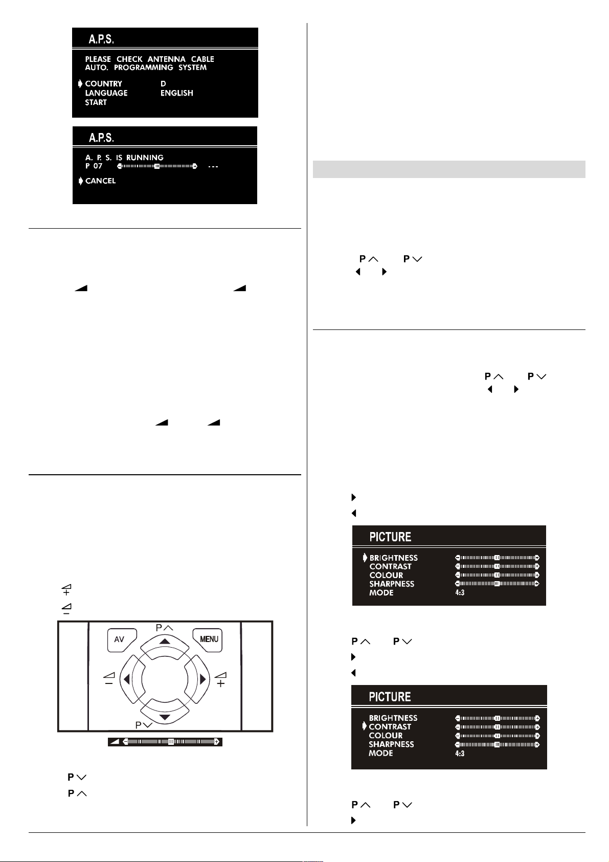
Operating with the onset buttons
Volume setting and programme selection can be made using
the buttons on the front panel.
Volume Setting
Press - button to decrease volume or + button to
increase volume, so a volume level scale will be displayed
on the screen.
Programme Selecting
Press P/CH+ button to select next programme or -P/CH
button to select the previous programme.
Entering Main Menu
Press MENU button to enter main menu. In the main
menu select submenu using P/CH+ or -P/CH button and
enter the submenu using + or - button. To learn
the usage of the menus, refer to Menu System on page
5.
Operating with Remote Control
The remote control handset of your TV is designed to control
all the functions of the model you selected. The functions will
be described in accordance with the menu system of your
TV.
Functions which you can use out of menu system are described below.
Programme Selecting (direct access):
Press digit buttons on the remote control handset to select
programmes between 0 and 9. TV will switch to the selected
program after a short delay.
When you press first digit, second digit will be displayed with
- symbol for 3 seconds. To select programmes between 10
and 99 press corresponding digit buttons consecutively before - symbol on the second digit disappears. (e.g. for programme 27, first press 2 and then 7 while program number
displayed as 2- )
Menu System
Your TV has been designed with a menu system. Display
MENU (main menu) and enter one of four menus (PICTURE, FEATURE, INSTALL. and PROGRAM.).
1- Press MENU button to display MENU (main menu).
The menu titles will be displayed in the main menu.
2- Press or button to select a menu title, then
press or button to enter the menu.
To exit a menu, press STANDARD button.
To go to the previous menu, press MENU button.
Picture Menu
To change picture settings:
Press MENU button, now you are in main menu. In the
main menu, select PICTURE using or button,
then enter the picture menu pressing or button.
or,
Enter the Picture Menu directly, pressing the GREEN but-
ton.
Setting Brightness:
As you enter the picture menu, BRIGHTNESS will be the
first selected option.
Press button to increase BRIGHTNESS.
Press button to decrease BRIGHTNESS.
Volume Setting
Press button to increase volume.
Press button to decrease volume.
Programme Selecting (Previous or next programme)
Press button to select the previous programme.
Press button to select the next programme.
ENGLISH - 5 -
Setting Contrast:
Using or button select CONTRAST.
Press button to increase CONTRAST level.
Press button to decrease CONTRAST level.
Setting Colour:
Using or button select COLOUR.
Press button to increase COLOUR level.
Page 28
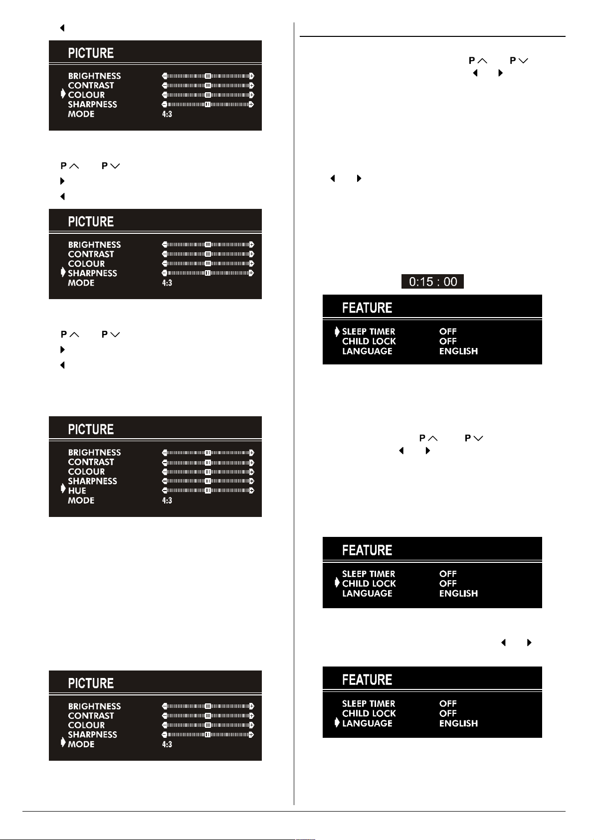
Press button to decrease COLOUR level.
Setting Sharpness:
Using or button select SHARPNESS.
Press button to increase SHARPNESS level.
Press button to decrease SHARPNESS level.
Setting Hue (In AV mode only) :
Feature Menu
Press MENU button, now you are in main menu. In the
main menu, select FEATURE, using or button.
Then enter the feature menu pressing or button.
or,
Enter the Feature Menu directly, pressing the YELLOW
button.
Sleep Timer:
As you enter the feature menu, SLEEP TIMER will be the
first selected option.
Use
between OFF, 0:15:00, 0:30:00, 0:45:00, 1:00:00, 1:15:00,
1:30:00, 1:45:00 and 2:00:00. hours. Your TV will get into
standby mode when the period you selected passes after
you make the selection.
It is displayed on the upper right of the screen. If sleep timer
is activated it is displayed with the TV status and erased with
it after 3 seconds.
or button to change the value of the sleep timer
Using or button select HUE.
Press button to increase HUE level.
Press button to decrease HUE level.
HUE adjust is functional only when NTSC 3.58/4.43 is applied in AV mode. It does not appear when other colour systems used.
Mode:
This option is used to change the picture size according to
the coming transmission.
If AUTO function is selected, then the picture size will be
automatically changed according to the transmission.
Selecting 4 : 3 mode forces picture ratio size to 4 : 3.
Selecting 16 : 9 mode forces picture ratio size to 16 : 9.
Every program has its own picture mode setting. When you
store the picture mode for a program other programs keep
their picture mode setting unaffected.
During the last minute of the count down, the timer is displayed on the upper right of the screen. When the timer
reaches zero, TV goes to stand-by.
Child Lock:
In Feature Menu, press or button to select
CHILD LOCK. Using or button turn CHILD LOCK On
or Off.
When Off is selected, there will be no difference in the operation of your TV. When On is selected, the TV can only be
controlled by the remote control handset. In this case, the
front panel buttons (except the Switch On/Off button) will not
work.
Language:
Menu Language can be selected by pressing or button
on LANGUAGE item.
ENGLISH - 6 -
Page 29

Install. Menu
Press MENU button, now you are in main menu. In the
main menu, select INSTALL. using or button,
then enter the Installation menu pressing or button.
or
Enter the Installation Menu directly, pressing the BLUE but-
ton.
To programme a channel in a TVs programme
number manually:
1. PROGRAMME will be the first selected item as you enter
the INSTALL. menu. Pressing or button select the
programme number where you want to the tuned channel
to be stored. (You may also type the programme number
using the digit buttons.)
B/G : C02-C73 / S01-S41 / S75-S79
D/K : C01-C69 / S01-S41
K1 : C04-C09
6. If the channel reception is poor, fine-tune the channel.
Press or button to select FINE TUNING,then
press or to fine-tune the channel.
7. After the all settings are completed, store the new
channels setting to the programme number which you se-
lected. Press or button to select STORE,
then press or to store it.
If you want to modify the current programme numbers
setting (for example, changing fine tuning, etc.) :
1. Select the programme number you want to modify the
settings while no menu appears.
2. Display the INSTALL. menu.
3. Follow To programme a channel in a TVs program-
me number manually: on page 7 and change the set-
tings of the current programme number.
If you want to name the new programme, follow the instructions under "To change the name of a programme"
on page 7.
Note:
Do not use Programme item in the INSTALL. menu to select
the programme number. If you select the programme number
with Programme item and store the settings, the selected
programme numbers current settings are cancelled.
2. Press or button to select BAND. Using or
button to select the band in which you want to search a
channel.
3. Press or button to select SEARCH. Press
or button to start searching. (Press button to search
forward.Press button to search backwards.)
If the found channel is not the desired one, press or
button to start searching again.
To stop searching before a channel is found, press the reverse direction button. For example, when the TV is searching forward with button, press button to stop searching.
If you know the channel number which you want to find, you
can find the channel directly.
Press or button to select CHANNEL, then press
or button to select the channel number, or enter the
number with the digit buttons.
(Follow the step 5 to select the correct standard before you
select a channel number.)
4. If you want to name the new programme, follow the instructions under "To change the name of a programme" on
page 7.
5. If the sound or picture is abnormal, change the standard
(broadcasting system) of new channel.
Press or button to select STANDARD, then
press or button to change the correct one.
The indicated channel number will be changed when you
change the standard.
Program. (Programming) Menu
PROGRAM. (Programming) menu is used to display the
programme names and numbers. You can use this menu to
delete a channel, to insert a channel and to autostore the
programmes.
Select the PROGRAM. menu pressing or button and open it pressing or button. When you enter the
programme menu, all the programme numbers and names
will be displayed on the screen. The programme number and
name of the tuned channel will be shown by the cyan color.
All the other channel numbers will be white. You can move
the number in cyan using or or or button.
Also, it's possible to use digit buttons to select programme
numbers. As you pass through the programme numbers this
way, to reach the programme number you want, the channels
corresponding to the programme numbers you pass through
will be tuned and the selected programme number will be
shown in cyan.
To change the name of a programme:
Move to the channel you want to rename or use the digits
so that the selected programme number is in cyan color.
ENGLISH - 7 -
Page 30

Press the RED button. Use or button to select the
position and press
Now, press the RED button again to store or BLUE button to
cancel NAME.
To delete a channel from a programme number:
Move to the channel you want to delete or use the digits so
that the selected programme number is in cyan color.
Press the YELLOW button. Now the corresponding channel
will be deleted and all the other channels below this programme number will be moved one programme number up.
Now, press the YELLOW button again to delete or BLUE button to cancel DELETE.
To insert a channel into a programme number:
Move to the channel to be inserted or use the digits so that
the selected programme number is in cyan color.
Press the GREEN button. Now using
or buttons, move to the programme number.
Now, press the GREEN button again to insert or BLUE button
to cancel INSERT.
A.P.S.
If you enter the A.P.S. menu, you can automatically program-
me the received channels in your TVs programmes with
A.P.S. ( Automatic programme system ).
1. After displaying the PROGRAM. menu, press the BLUE
button to enter the A.P.S. menu.
2. Select LANGUAGE with the or button, then
press the or button to select a menu language.
3. Select COUNTRY with the or button, then
press the or button to select the country you are
now located.
4. If you want to start programming, select START with the
or button, then press the button. The
message A.P.S. IS RUNNING appears and A.P.S. auto-
matically programmes the received channels in your TVs
programme numbers. Afrer A.P.S. is finalized, the PRO-
GRAM. menu appears again.
To cancel A.P.S., press the button.
or button to select a letter.
or or
Other Features
Sound Mute
To cut off the sound of the TV, press button. The sound
will be cut off. To cancel mute, press or or button. The volume level will be the same as the level before
mute when you cancel mute.
Information on Screen
First pressing the button displays the current status
Programme number and Station name.
Pressing this button again displays the current time.
Pressing this button once more remove the on-screen display.
To Display the Time
While watching a TV programme with Teletext transmission
press button twice. The current time information, captured from Teletext will be displayed on the screen.
If the programme being watched does not have Teletext
transmission, only a box will be displayed at the same location.
The time information will disappear after pressing but-
ton again.
When time information is displayed on screen, entering another menu will remove it.
Standard
You can re-set the current PICTURE menu settings (except
Picture Mode setting) to the default settings.
Press STANDARD button when no menu appears.
VCR Control Buttons
The buttons can be used to operate a JVC brand VCR.
Pressing the button having the same appearance as the original remote control button of a device makes the function work
in the same way as the original remote control.
Press the VCR Control Button to control your VCR.
Note:
If your device is not made by JVC, these buttons cannot be
used.
Even if your device is made by JVC, some of these buttons
or any one of the buttons may not work, depending on the
device.
You can use the / buttons to choose a TV channel
which the VCR will receive.
ENGLISH - 8 -
Page 31

Teletext
Teletext is an information system that displays text on your
TV screen. Using the Teletext information system you can
view a page of information on a subject that is available in the
list of contents (index).
No on screen display will be available in text mode.
No contrast, brightness or colour control, but volume control
is available in text mode.
To operate Teletext
Select a TV station on which Teletext is being transmitted.
Press (TELETEXT) button. Usually the list of contents
(index) is displayed on the screen.
To Select Double Height Text
Press button for the top half of the information page to
be displayed in double height text.
Press
tion page to be displayed in double height text.
Press
height text.
button again for the bottom half of the informa-
button once more for the full page of normal
To Reveal concealed Information
Pressing button once will reveal answers on a quiz or
games page.
Pressing button again will conceal the revealed an-
swers.
To Stop Automatic Page Change
The teletext page you have selected may contain more information than what is on the screen; the rest of the information
will be displayed after a period of time.
Press button to stop the automatic page change.
Press button again to allow the next page to be dis-
played.
To select a page of Teletext
Press the appropriate digit buttons for the required Teletext
page number.
The selected page number is displayed at the top left corner
of the screen. The Teletext page counter searches until the
selected page number is located, so that the desired page is
displayed on the screen.
Press button to move the Teletext screen forward
one page at a time.
Press button to move the Teletext screen backward
one page at a time.
To Select Index Page
To select the page number of the index (generally page
100), press button.
To Select a Subcode Page
Subcode pages are subsections of long Teletext pages that
can only be displayed on the screen one section at a time.
Select the required Teletext page.
Press button.
Select the required subcode page number by pressing four
digit buttons (e.g. 0001).
If the selected subcode page is not displayed in a short
time, press button. TV programme will be displayed on
the screen.
Teletext page number will be displayed on the upper left cor-
ner of the screen when the selected page is found.
Press button to display the selected Teletext page.
To exit Teletext
Press button. The screen will switch to TV mode.
Searching for a teletext page while watching TV
In the Teletext mode pressing button will switch the
screen to the TV mode. In the TV mode enter a page number using digit keys. As you enter last digit of page number,
sign will replace the page number and flash until the
entered page number is found. Then the page number will
replace sign again. Now you can display this teletext
page pressing button.
ENGLISH - 9 -
Page 32

Connect the External Equipments
Before connecting anything
Switch off all equipments including the TV.
Read the manuals provided with the equipments.
To select an AV mode
Pressing AV button on the remote control selects one of the three AV modes (AV- 1, AV-1 S and F-AV).
To return to the TV mode, repeatedly press AV button or press or button.
AV-1 (SCART 1) terminal: Euroconnector (21-pin, SCART)
Video input, Audio input and RGB inputs are available.
TV broadcast outputs (Video and Audio) are available.
AV-1 S (SCART 1) terminal: Euroconnector (21-pin, SCART)
Video input, S-VIDEO (Y/C) input and Audio input are available.
Video and Audio outputs are available.
F-AV (Front AV) terminal: RCA connectors x 2
Video input and Audio input are available.
$QWHQQD $9
$96
FRONT AV
)$9
ENGLISH - 10 -
Page 33

Via the Euroconnector
Your TV set has an Euroconnector socket. If you want to
connect equipments (e.g. video recorder, decoder, etc.) which
have Euroconnectors, to your TV, use the AV-1 (SCART 1) or
AV-1 S (SCART 1) terminals.
AV-1 S Mode
If the equipment connected to your TV set supports S-Video
(Y/C) output from Euroconnector, you can have a better picture quality by selecting AV-1 S mode and connecting your
equipment to the AV-1 S (SCART 1) terminal of TV. See your
equipment's booklet to check if your equipment has such feature.
Via the RCA jacks
If you have an equipment (such as a Camcorder) which has
the RCA jacks, connect it to the F-AV (Front AV) terminal
with the video and audio cables.
Via the ANT (aerial) socket
If your equipment does not have an Euroconnecter or RCA
jacks, connect it to the TV with an aerial cable. For details,
see the manual provided with the equipment.
To store the test signal that comes from the equipment, see
"Install. Menu" on page 7 and store it to the programme
number 0. You can watch images from that equipment to
select the programme number which you stored the test
signal.
TV and Video Recoder (VCR)
Connect the Video Recorder to the ANT (antenna input)
socket of the TV with the aerial cable.
Connect the Video Recorder to the AV-1 or AV-1 S terminal
with the SCART cable, or connect it to the F-AV (Front AV)
terminal with the audio and video cables.
NTSC Playback
Connect a NTSC video recorder to a terminal. Then press
AV button to select the corresponding AV mode.
NTSC 3.58/4.43 system is detected automatically in AV
mode.
Tips
Care of the Screen:
Clean the screen with a slightly damp, soft cloth. Do not use
abrasive solvents as they may damage the TV screen coating
layer.
Poor Picture:
Have you selected the correct TV system? Is your TV set or
house aerial located too close to the loudspeakers, nonearthed audio equipment or neon lights, etc. ?
Mountains or high buildings can cause double pictures or
ghost images. Sometimes you can improve the picture quality by changing the direction of the aerial.
The picture quality may degrade when two peripherals are
connected to the TV at the same time. In such a case, disconnect one of the peripherals.
No Picture:
Is the aerial connected properly? Are the plugs connected
tightly to the aerial socket? Is the aerial cable damaged? Are
suitable plugs used to connect the aerial? If you are in doubt,
consult your dealer.
No Picture means that your TV is not receiving any transmission. Have you pressed the correct keys on the remote
control? Try once more.
Remote Control:
Your TV no longer responds to the remote control. Press the
STANDARD button on the remote control once more. Per-
haps the batteries are exhausted. If so you can still use the
local buttons at the front of your TV.
Have you selected the wrong menu? Press STANDARD but-
ton to return to TV mode or press MENU button to return to
the previous menu.
No solution:
Switch your TV set off and on. If this does not work, call the
service personnel; never attempt to repair it yourself.
Connecting Headphones
Use the headphone socket of your TV, to connect headphones.
ENGLISH - 11 -
Page 34

Specifications
TV BROADCASTING .......................................... PAL SECAM B/G D/K K1
RECEIVING CHANNELS ..................................... VHF (BAND I/III)
UHF (BAND U)
HYPERBAND
CABLE TV (B/G : S01-S41 / S75-S79 ; D/K: S01-S41)
NUMBER OF PRESET CHANNELS ................... 100
CHANNEL INDICATOR ........................................ On Screen Display
RF AERIAL INPUT .............................................. 75 Ohm (unbalanced)
OPERATING VOLTAGE ...................................... 220-240V AC, 50 Hz.
SOUND-MULTIPLEX SYSTEMS .......................... Mono
PICTURE TUBE .................................................. For 21
AUDIO OUTPUT POWER
(W
) (%1 THD) .................................... 5,5
RMS.
POWER CONSUMPTION (W) (max.) .................. 85
DIMENSIONS (mm) ................................... AV-21KJ1SEF
D........................................................................ 480
L ........................................................................ 610
H........................................................................ 450
Weight (Kg.).......................................................21
ENGLISH - 12 -
Page 35

VICTOR COMPANY OF JAPAN, LIMITED
©2003 VICTOR COMPANY OF JAPAN, LIMITED
50036407
0203-JVC
Page 36

AV-21KJ1SNF
ENGLISH
FRANÇAIS
DEUTSCH
ITALIANO
CASTELLANO
NEDERLANDS
PORTUGUÊS
SVENSKA
NORSK
DANSK
SUOMI
COLOUR TELEVISION
TELEVISEUR COULEUR
FARBFERNSEHGERÄT
TELEVISORE A COLORI
TELEVISOR A COLOR
KLEURENTELEVISIE
TELEVISOR A CORES
FÄRG- TV
FARGEFJERNSYN
FARVEFJERNSYN
VÄRITELEVISIO
INSTRUCTIONS
MANUEL D'INSTRUCTIONS
BEDIENUNGSANLEITUNG
ISTRUZIONI
MANUAL DE INSTRUCCIONES
GEBRUIKSAANWIJZING
INSTRUÇÕES
BRUKSANVISNING
BRUKSANVISNING
INSTRUKTIONSBOG
KÄYTTÖOHJE
Page 37

Contents
Safety Precautions
Safety Precautions ................................................... 1
Remote Control Buttons .......................................... 2
Control Panel Buttons .............................................. 3
Antenna Connections ...............................................3
Preparation ................................................................ 4
Features .......................................................................... 4
Before Switching on your TV .................................. 4
Power connection............................................................. 4
Aerial Connections ........................................................... 4
How to connect the external equipments .......................... 4
Inserting batteries in the remote control handset .............. 4
Switching the TV ON/OFF ........................................4
To switch the TV on.......................................................... 4
To switch the TV off .......................................................... 4
Initial Settings ........................................................... 4
Operating with the onset buttons ...................................... 5
Operating with Remote Control ......................................... 5
Menu System .............................................................5
Picture Menu ................................................................... 5
Feature Menu ................................................................... 6
Install. Menu .................................................................... 7
Program. (Programming) Menu ........................................ 7
Other Features.......................................................... 8
Sound Mute ..................................................................... 8
Information on Screen ...................................................... 8
To Display the Time.......................................................... 8
Standard .......................................................................... 8
VCR Control Buttons ........................................................ 8
Teletext...................................................................... 9
To operate Teletext ........................................................... 9
To select a page of Teletext.............................................. 9
To Select Index Page ....................................................... 9
Searching for a teletext page while watching TV ............... 9
To Select Double Height Text ........................................... 9
To Reveal concealed Information .................................... 9
To Stop Automatic Page Change ...................................... 9
To Select a Subcode Page ............................................... 9
To exit Teletext ................................................................. 9
Connect the External Equipments ........................ 10
Via the Euroconnector..................................................... 11
AV-1 S Mode ................................................................... 11
Via the RCA jacks ........................................................... 11
Via the ANT (aerial) socket .............................................. 11
TV and Video Recoder (VCR) .......................................... 11
NTSC Playback .............................................................. 11
Connecting Headphones ................................................. 11
Tips........................................................................... 11
Specifications ..........................................................12
1. Power Source
The receiver should be operated only from a 220-240V AC,
50 Hz. outlet. Ensure you select the correct voltage setting
for your convenience.
2. Power Cord
The power supply cord should be placed so that they are not
likely to be walked on or pinched by items placed upon them
or against them. Pay particular attention to cord where they
enter the plug, power outlet, and the point where they exit
from the receiver.
3. Moisture and Water
Do not use this equipment in a humid and damp place (avoid
the bathroom, the sink in the kitchen, and near the washing
machine). Do not expose this equipment to rain or water and
do not place objects filled with liquids on it as this may be
dangerous.
4. Cleaning
Before cleaning, unplug the receiver from the main supply
outlet. Do not use liquid or aerosol cleaners. Use with soft
and dry cloth.
5. Ventilation
The slots and openings on the receiver are intended for ventilation and to ensure reliable operation. To prevent overheating,
these openings must not be blocked or covered in anyway.
6. Lightning
In case of storm and lightning or when going on holiday, disconnect the power cord from the wall outlet.
7. Replacement Part
When replacement parts are required, be sure the service
technician has used replacement parts which are specified
by the manufacturer or have the same specifications as the
original one. Unauthorized substitutions may result in fire,
electrical shock, or other hazards.
8. Servicing
Please refer all servicing to qualified personnel. Do not remove cover as this may result in electric shock.
9. Flame sources
Do not place naked flame sources on the apparatus.
10. Stand-By
Do not leave your TV stand-by or operating condition when you
leave your house.
Warning!
Any intervention contrary to regulations, in particular, any
modification of high voltage or a replacement of the picture
tube may lead to an increased concentration of x-rays. Any
television modified in this way no longer complies with license
and must not be operated.
Instructions for waste disposal:
Packaging and packaging aids are recyclable and should
principally be recycled. Packaging materials, such as foil
bag, must be kept away from children.
ENGLISH - 1 -
Page 38

Remote Control Buttons
= Stand By / Power
0 - 9 = Direct Program
Standard Button (PICTURE default settings)
Colour Buttons
MENU = Menu Button
( ) = Cursor Up / Programme Up
( ) = Cursor Right / Volume +
Teletext Control Buttons
VCR Control Buttons
( ) = Cursor Down / Programme Down
( ) = Cursor Left / Volume -
AV = AV Button
= Information Button
= Mute
CAUTION
RISK OF ELECTRIC SHOCK
The lightning flash with arrowhead symbol, within an equilateral triangle, is intended to alert the user to the presence of
uninsulated "dangerous voltage" within the product's enclosure that may be of sufficient magnitude to constitute a risk
of electric shock of persons.
The exclamation point within an equilateral triangle is intended to alert the user to the presence of important operating
and maintenance (servicing) instructions in the literature accompanying the appliance.
ENGLISH - 2 -
Page 39

Control Panel Buttons
+HDGSKRQH
)5217$9
3RZHU 0HQX
9ROXPH
3URJUDP
Antenna Connections
$XGLR,QSXW
7HUP L QD O
9LGHR,QSXW
7HUPLQD O
ENGLISH - 3 -
Page 40

Preparation
Place TV on a solid surface.
For ventilation, leave a space of at least 10 cm free all around
the set. To prevent any fault and unsafe situations, please do
not place any objects on top of the set.
Features
It is a remote controlled colour television.
100 programmes from VHF, UHF bands or cable channels
can be preset.
It can tune cable channels.
Controlling the TV is very easy by its menu driven system.
It has an Euroconnector socket for external devices (such
as video recorder, video games, audio set, etc.)
Front AV Input available.
Teletext.
It is possible to connect headphone.
Direct channel access.
APS (Automatic Programming System).
All programmes can be named.
Forward or backward automatic tuning.
Sleep timer.
Automatic sound mute when no transmission.
5 minutes after the broadcasting (closedown), the TV
switches itself automatically to stand-by mode.
Before Switching on your TV
Power connection
Important: The TV set is designed to operate on 220-240 V
AC, 50 Hz.
After unpacking, allow the TV set to reach the ambient room
temperature before you connect the set to the mains.
Aerial Connections
Connect the aerial plug to the aerial input socket located at
the back of the TV.
How to connect the external equipments
See Connect the External Equipments on page 10.
See the instruction manuals provided with the external de-
vices too.
Inserting batteries in the remote control handset
Remove the battery cover located on the back of the hand-
set by gently pulling upwards from the indicated part.
Insert two AA (R6) or equivalent type batteries inside.
Replace the battery cover.
NOTE: Remove batteries from remote control handset when it is
not to be used for a long period. Otherwise it can be damaged
due to any leakage of batteries.
Switching the TV ON/OFF
You can operate your TV either using the remote control
handset or directly using the TV onset buttons.
To switch the TV on
Your TV will switch on in two steps:
1- Press the power button located on the front of the TV. Then
the TV switches itself to standby mode and the RED LED
located below the TV turns on.
2- To switch on the TV from stand-by mode either:
Press a digit button on the remote control so that a program-
me number is selected,
or,
Press Standby / Power Button or Programme Up and Down
buttons on the front of the TV or on the remote control respectively, so the TV will switch on and the RED Led will turn
GREEN.
To switch the TV off
Press the stand-by button on the remote control, so the TV
will switch to stand-by mode and the GREEN LED will become RED, or,
Press the power button located on the front of the TV.
Initial Settings
The message "PLEASE CHECK ANTENNA CABLE AUTO.
PROGRAMMING SYSTEM" will be displayed when you turn
on your TV for the first time.
1- Select LANGUAGE with the or button, then
press the or button to select a menu language.
2- Select COUNTRY with the or button, then
press the or button to select the country you are
now located.
3- Select START with the or button, then press
the button to start APS.
APS (Automatic Programming System) automatically pro-
grammes the received channels in your TVs programme
numbers. During APS, "A. P. S. IS RUNNING" will be dis-
played. After APS is finalized, the PROGRAM. menu appears.
To cancel APS, press the button.
You can delete a channel, insert a channel into a programme
number, or re-start APS with the PROGRAM. menu.
For details, see Program. (Programming) Menu on page
7.
4- Press the "STANDARD" button to complete the initial set-
tings.
After the initial settings are complete, you can change a programme number or to name a programme number or to programme new channel manually. For details, see
Install. Menu on page 7.
If the message "PLEASE CHECK ANTENNA CABLE AUTO.
PROGRAMMING SYSTEM" does not appear, follow the description Program. (Programming) Menu on page 7 to
select a menu language and the country where you are now
located, and to use A.P.S..
ENGLISH - 4 -
Page 41

Operating with the onset buttons
Volume setting and programme selection can be made using
the buttons on the front panel.
Volume Setting
Press - button to decrease volume or + button to
increase volume, so a volume level scale will be displayed
on the screen.
Programme Selecting
Press P/CH+ button to select next programme or -P/CH
button to select the previous programme.
Entering Main Menu
Press MENU button to enter main menu. In the main
menu select submenu using P/CH+ or -P/CH button and
enter the submenu using + or - button. To learn
the usage of the menus, refer to Menu System on page
5.
Operating with Remote Control
The remote control handset of your TV is designed to control
all the functions of the model you selected. The functions will
be described in accordance with the menu system of your
TV.
Functions which you can use out of menu system are described below.
Programme Selecting (direct access):
Press digit buttons on the remote control handset to select
programmes between 0 and 9. TV will switch to the selected
program after a short delay.
When you press first digit, second digit will be displayed with
- symbol for 3 seconds. To select programmes between 10
and 99 press corresponding digit buttons consecutively before - symbol on the second digit disappears. (e.g. for programme 27, first press 2 and then 7 while program number
displayed as 2- )
Menu System
Your TV has been designed with a menu system. Display
MENU (main menu) and enter one of four menus (PICTURE, FEATURE, INSTALL. and PROGRAM.).
1- Press MENU button to display MENU (main menu).
The menu titles will be displayed in the main menu.
2- Press or button to select a menu title, then
press or button to enter the menu.
To exit a menu, press STANDARD button.
To go to the previous menu, press MENU button.
Picture Menu
To change picture settings:
Press MENU button, now you are in main menu. In the
main menu, select PICTURE using or button,
then enter the picture menu pressing or button.
or,
Enter the Picture Menu directly, pressing the GREEN but-
ton.
Setting Brightness:
As you enter the picture menu, BRIGHTNESS will be the
first selected option.
Press button to increase BRIGHTNESS.
Press button to decrease BRIGHTNESS.
Volume Setting
Press button to increase volume.
Press button to decrease volume.
Programme Selecting (Previous or next programme)
Press button to select the previous programme.
Press button to select the next programme.
ENGLISH - 5 -
Setting Contrast:
Using or button select CONTRAST.
Press button to increase CONTRAST level.
Press button to decrease CONTRAST level.
Setting Colour:
Using or button select COLOUR.
Press button to increase COLOUR level.
Page 42

Press button to decrease COLOUR level.
Setting Sharpness:
Using or button select SHARPNESS.
Press button to increase SHARPNESS level.
Press button to decrease SHARPNESS level.
Setting Hue (In AV mode only) :
Feature Menu
Press MENU button, now you are in main menu. In the
main menu, select FEATURE, using or button.
Then enter the feature menu pressing or button.
or,
Enter the Feature Menu directly, pressing the YELLOW
button.
Sleep Timer:
As you enter the feature menu, SLEEP TIMER will be the
first selected option.
Use
between OFF, 0:15:00, 0:30:00, 0:45:00, 1:00:00, 1:15:00,
1:30:00, 1:45:00 and 2:00:00. hours. Your TV will get into
standby mode when the period you selected passes after
you make the selection.
It is displayed on the upper right of the screen. If sleep timer
is activated it is displayed with the TV status and erased with
it after 3 seconds.
or button to change the value of the sleep timer
Using or button select HUE.
Press button to increase HUE level.
Press button to decrease HUE level.
HUE adjust is functional only when NTSC 3.58/4.43 is applied in AV mode. It does not appear when other colour systems used.
Mode:
This option is used to change the picture size according to
the coming transmission.
If AUTO function is selected, then the picture size will be
automatically changed according to the transmission.
Selecting 4 : 3 mode forces picture ratio size to 4 : 3.
Selecting 16 : 9 mode forces picture ratio size to 16 : 9.
Every program has its own picture mode setting. When you
store the picture mode for a program other programs keep
their picture mode setting unaffected.
During the last minute of the count down, the timer is displayed on the upper right of the screen. When the timer
reaches zero, TV goes to stand-by.
Child Lock:
In Feature Menu, press or button to select
CHILD LOCK. Using or button turn CHILD LOCK On
or Off.
When Off is selected, there will be no difference in the operation of your TV. When On is selected, the TV can only be
controlled by the remote control handset. In this case, the
front panel buttons (except the Switch On/Off button) will not
work.
Language:
Menu Language can be selected by pressing or button
on LANGUAGE item.
ENGLISH - 6 -
Page 43

Install. Menu
Press MENU button, now you are in main menu. In the
main menu, select INSTALL. using or button,
then enter the Installation menu pressing or button.
or
Enter the Installation Menu directly, pressing the BLUE but-
ton.
To programme a channel in a TVs programme
number manually:
1. PROGRAMME will be the first selected item as you enter
the INSTALL. menu. Pressing or button select the
programme number where you want to the tuned channel
to be stored. (You may also type the programme number
using the digit buttons.)
1. Select the programme number you want to modify the
settings while no menu appears.
2. Display the INSTALL. menu.
3. Follow To programme a channel in a TVs program-
me number manually: on page 7 and change the set-
tings of the current programme number.
If you want to name the new programme, follow the instructions under "To change the name of a programme"
on page 7.
Note:
Do not use Programme item in the INSTALL. menu to select
the programme number. If you select the programme number
with Programme item and store the settings, the selected
programme numbers current settings are cancelled.
Program. (Programming) Menu
PROGRAM. (Programming) menu is used to display the
programme names and numbers. You can use this menu to
delete a channel, to insert a channel and to autostore the
programmes.
Select the PROGRAM. menu pressing or button and open it pressing or button. When you enter the
programme menu, all the programme numbers and names
will be displayed on the screen. The programme number and
name of the tuned channel will be shown by the cyan color.
All the other channel numbers will be white. You can move
the number in cyan using or or or button.
Also, it's possible to use digit buttons to select programme
numbers. As you pass through the programme numbers this
way, to reach the programme number you want, the channels
corresponding to the programme numbers you pass through
will be tuned and the selected programme number will be
shown in cyan.
2. Press or button to select BAND. Using or
button to select the band in which you want to search a
channel.
3. Press or button to select SEARCH. Press
or button to start searching. (Press button to search
forward.Press button to search backwards.)
If the found channel is not the desired one, press or
button to start searching again.
To stop searching before a channel is found, press the reverse direction button. For example, when the TV is searching forward with button, press button to stop searching.
If you know the channel number which you want to find, you
can find the channel directly.
Press or button to select CHANNEL, then press
or button to select the channel number, or enter the
number with the digit buttons.
4. If you want to name the new programme, follow the instructions under "To change the name of a programme" on
page 7.
5. If the channel reception is poor, fine-tune the channel.
Press or button to select FINE TUNING,then
press or to fine-tune the channel.
6. After the all settings are completed, store the new
channels setting to the programme number which you se-
lected. Press or button to select STORE,
then press or to store it.
If you want to modify the current programme numbers
setting (for example, changing fine tuning, etc.) :
To change the name of a programme:
Move to the channel you want to rename or use the digits
so that the selected programme number is in cyan color.
Press the RED button. Use or button to select the
position and press or button to select a letter.
Now, press the RED button again to store or BLUE button to
cancel NAME.
To delete a channel from a programme number:
Move to the channel you want to delete or use the digits so
that the selected programme number is in cyan color.
Press the YELLOW button. Now the corresponding channel
will be deleted and all the other channels below this programme number will be moved one programme number up.
Now, press the YELLOW button again to delete or BLUE button to cancel DELETE.
ENGLISH - 7 -
Page 44

To insert a channel into a programme number:
Move to the channel to be inserted or use the digits so that
the selected programme number is in cyan color.
Press the GREEN button. Now using or or
or buttons, move to the programme number.
Now, press the GREEN button again to insert or BLUE button
to cancel INSERT.
A.P.S.
If you enter the A.P.S. menu, you can automatically program-
me the received channels in your TVs programmes with
A.P.S. ( Automatic programme system ).
1. After displaying the PROGRAM. menu, press the BLUE
button to enter the A.P.S. menu.
2. Select LANGUAGE with the or button, then
press the or button to select a menu language.
3. Select COUNTRY with the or button, then
press the or button to select the country you are
now located.
4. If you want to start programming, select START with the
or button, then press the button. The
message A.P.S. IS RUNNING appears and A.P.S. auto-
matically programmes the received channels in your TVs
programme numbers. Afrer A.P.S. is finalized, the PRO-
GRAM. menu appears again.
To cancel A.P.S., press the button.
Other Features
Sound Mute
To cut off the sound of the TV, press button. The sound
will be cut off. To cancel mute, press or or button. The volume level will be the same as the level before
mute when you cancel mute.
Information on Screen
First pressing the button displays the current status
Programme number and Station name.
Pressing this button again displays the current time.
Pressing this button once more remove the on-screen display.
To Display the Time
While watching a TV programme with Teletext transmission
press button twice. The current time information, captured from Teletext will be displayed on the screen.
If the programme being watched does not have Teletext
transmission, only a box will be displayed at the same location.
The time information will disappear after pressing but-
ton again.
When time information is displayed on screen, entering another menu will remove it.
Standard
You can re-set the current PICTURE menu settings (except
Picture Mode setting) to the default settings.
Press STANDARD button when no menu appears.
VCR Control Buttons
The buttons can be used to operate a JVC brand VCR.
Pressing the button having the same appearance as the original remote control button of a device makes the function work
in the same way as the original remote control.
Press the VCR Control Button to control your VCR.
Note:
If your device is not made by JVC, these buttons cannot be
used.
Even if your device is made by JVC, some of these buttons
or any one of the buttons may not work, depending on the
device.
You can use the / buttons to choose a TV channel
which the VCR will receive.
ENGLISH - 8 -
Page 45

Teletext
Teletext is an information system that displays text on your
TV screen. Using the Teletext information system you can
view a page of information on a subject that is available in the
list of contents (index).
No on screen display will be available in text mode.
No contrast, brightness or colour control, but volume control
is available in text mode.
To operate Teletext
Select a TV station on which Teletext is being transmitted.
Press (TELETEXT) button. Usually the list of contents
(index) is displayed on the screen.
To Select Double Height Text
Press button for the top half of the information page to
be displayed in double height text.
Press
tion page to be displayed in double height text.
Press
height text.
button again for the bottom half of the informa-
button once more for the full page of normal
To Reveal concealed Information
Pressing button once will reveal answers on a quiz or
games page.
Pressing button again will conceal the revealed an-
swers.
To Stop Automatic Page Change
The teletext page you have selected may contain more information than what is on the screen; the rest of the information
will be displayed after a period of time.
Press button to stop the automatic page change.
Press button again to allow the next page to be dis-
played.
To select a page of Teletext
Press the appropriate digit buttons for the required Teletext
page number.
The selected page number is displayed at the top left corner
of the screen. The Teletext page counter searches until the
selected page number is located, so that the desired page is
displayed on the screen.
Press button to move the Teletext screen forward
one page at a time.
Press button to move the Teletext screen backward
one page at a time.
To Select Index Page
To select the page number of the index (generally page
100), press button.
To Select a Subcode Page
Subcode pages are subsections of long Teletext pages that
can only be displayed on the screen one section at a time.
Select the required Teletext page.
Press button.
Select the required subcode page number by pressing four
digit buttons (e.g. 0001).
If the selected subcode page is not displayed in a short
time, press button. TV programme will be displayed on
the screen.
Teletext page number will be displayed on the upper left cor-
ner of the screen when the selected page is found.
Press button to display the selected Teletext page.
To exit Teletext
Press button. The screen will switch to TV mode.
Searching for a teletext page while watching TV
In the Teletext mode pressing button will switch the
screen to the TV mode. In the TV mode enter a page number using digit keys. As you enter last digit of page number,
sign will replace the page number and flash until the
entered page number is found. Then the page number will
replace sign again. Now you can display this teletext
page pressing button.
ENGLISH - 9 -
Page 46

Connect the External Equipments
Before connecting anything
Switch off all equipments including the TV.
Read the manuals provided with the equipments.
To select an AV mode
Pressing AV button on the remote control selects one of the three AV modes (AV- 1, AV-1 S and F-AV).
To return to the TV mode, repeatedly press AV button or press or button.
AV-1 (SCART 1) terminal: Euroconnector (21-pin, SCART)
Video input, Audio input and RGB inputs are available.
TV broadcast outputs (Video and Audio) are available.
AV-1 S (SCART 1) terminal: Euroconnector (21-pin, SCART)
Video input, S-VIDEO (Y/C) input and Audio input are available.
Video and Audio outputs are available.
F-AV (Front AV) terminal: RCA connectors x 2
Video input and Audio input are available.
$QWHQQD $9
$96
FRONT AV
)$9
ENGLISH - 10 -
Page 47

Via the Euroconnector
Your TV set has an Euroconnector socket. If you want to
connect equipments (e.g. video recorder, decoder, etc.) which
have Euroconnectors, to your TV, use the AV-1 (SCART 1) or
AV-1 S (SCART 1) terminals.
AV-1 S Mode
If the equipment connected to your TV set supports S-Video
(Y/C) output from Euroconnector, you can have a better picture quality by selecting AV-1 S mode and connecting your
equipment to the AV-1 S (SCART 1) terminal of TV. See your
equipment's booklet to check if your equipment has such feature.
Via the RCA jacks
If you have an equipment (such as a Camcorder) which has
the RCA jacks, connect it to the F-AV (Front AV) terminal
with the video and audio cables.
Via the ANT (aerial) socket
If your equipment does not have an Euroconnecter or RCA
jacks, connect it to the TV with an aerial cable. For details,
see the manual provided with the equipment.
To store the test signal that comes from the equipment, see
"Install. Menu" on page 7 and store it to the programme
number 0. You can watch images from that equipment to
select the programme number which you stored the test
signal.
TV and Video Recoder (VCR)
Connect the Video Recorder to the ANT (antenna input)
socket of the TV with the aerial cable.
Connect the Video Recorder to the AV-1 or AV-1 S terminal
with the SCART cable, or connect it to the F-AV (Front AV)
terminal with the audio and video cables.
NTSC Playback
Connect a NTSC video recorder to a terminal. Then press
AV button to select the corresponding AV mode.
NTSC 3.58/4.43 system is detected automatically in AV
mode.
Tips
Care of the Screen:
Clean the screen with a slightly damp, soft cloth. Do not use
abrasive solvents as they may damage the TV screen coating
layer.
Poor Picture:
Have you selected the correct TV system? Is your TV set or
house aerial located too close to the loudspeakers, nonearthed audio equipment or neon lights, etc. ?
Mountains or high buildings can cause double pictures or
ghost images. Sometimes you can improve the picture quality by changing the direction of the aerial.
The picture quality may degrade when two peripherals are
connected to the TV at the same time. In such a case, disconnect one of the peripherals.
No Picture:
Is the aerial connected properly? Are the plugs connected
tightly to the aerial socket? Is the aerial cable damaged? Are
suitable plugs used to connect the aerial? If you are in doubt,
consult your dealer.
No Picture means that your TV is not receiving any transmission. Have you pressed the correct keys on the remote
control? Try once more.
Remote Control:
Your TV no longer responds to the remote control. Press the
STANDARD button on the remote control once more. Per-
haps the batteries are exhausted. If so you can still use the
local buttons at the front of your TV.
Have you selected the wrong menu? Press STANDARD but-
ton to return to TV mode or press MENU button to return to
the previous menu.
No solution:
Switch your TV set off and on. If this does not work, call the
service personnel; never attempt to repair it yourself.
Connecting Headphones
Use the headphone socket of your TV, to connect headphones.
ENGLISH - 11 -
Page 48

Specifications
TV BROADCASTING .......................................... PAL B/G
RECEIVING CHANNELS ..................................... VHF (BAND I/III)
UHF (BAND U)
HYPERBAND
CABLE TV (S01-S41 / S75-S79)
NUMBER OF PRESET CHANNELS ................... 100
CHANNEL INDICATOR ........................................ On Screen Display
RF AERIAL INPUT .............................................. 75 Ohm (unbalanced)
OPERATING VOLTAGE ...................................... 220-240V AC, 50 Hz.
SOUND-MULTIPLEX SYSTEMS .......................... Mono
PICTURE TUBE .................................................. For 21
AUDIO OUTPUT POWER
(W
) (%1 THD) .................................... 5,5
RMS.
POWER CONSUMPTION (W) (max.) .................. 85
DIMENSIONS (mm) ................................... AV-21KJ1SNF
D........................................................................ 480
L ........................................................................ 610
H........................................................................ 450
Weight (Kg.).......................................................21
ENGLISH - 12 -
Page 49

VICTOR COMPANY OF JAPAN, LIMITED
©2003 VICTOR COMPANY OF JAPAN, LIMITED
50036405
0203-JVC
Page 50

AV-21KJ1SPF
ENGLISH
FRANÇAIS
DEUTSCH
ITALIANO
CASTELLANO
NEDERLANDS
PORTUGUÊS
COLOUR TELEVISION
TELEVISEUR COULEUR
FARBFERNSEHGERÄT
TELEVISORE A COLORI
TELEVISOR A COLOR
KLEURENTELEVISIE
TELEVISOR A CORES
INSTRUCTIONS
MANUEL D'INSTRUCTIONS
BEDIENUNGSANLEITUNG
ISTRUZIONI
MANUAL DE INSTRUCCIONES
GEBRUIKSAANWIJZING
INSTRUÇÕES
Page 51

Contents
Safety Precautions
Safety Precautions ................................................... 1
Remote Control Buttons .......................................... 2
Control Panel Buttons .............................................. 3
Antenna Connections ...............................................3
Preparation ................................................................ 4
Features .......................................................................... 4
Before Switching on your TV .................................. 4
Power connection............................................................. 4
Aerial Connections ........................................................... 4
How to connect the external equipments .......................... 4
Inserting batteries in the remote control handset .............. 4
Switching the TV ON/OFF ........................................4
To switch the TV on.......................................................... 4
To switch the TV off .......................................................... 4
Initial Settings ........................................................... 4
Operating with the onset buttons ...................................... 5
Operating with Remote Control ......................................... 5
Menu System .............................................................5
Picture Menu ................................................................... 5
Feature Menu ................................................................... 6
Install. Menu .................................................................... 7
Program. (Programming) Menu ........................................ 7
Other Features.......................................................... 8
Sound Mute ..................................................................... 8
Information on Screen ...................................................... 8
To Display the Time.......................................................... 8
Standard .......................................................................... 8
VCR Control Buttons ........................................................ 8
Teletext...................................................................... 9
To operate Teletext ........................................................... 9
To select a page of Teletext.............................................. 9
To Select Index Page ....................................................... 9
Searching for a teletext page while watching TV ............... 9
To Select Double Height Text ........................................... 9
To Reveal concealed Information .................................... 9
To Stop Automatic Page Change ...................................... 9
To Select a Subcode Page ............................................... 9
To exit Teletext ................................................................. 9
Connect the External Equipments ........................ 10
Via the Euroconnector..................................................... 11
AV-1 S Mode ................................................................... 11
Via the RCA jacks ........................................................... 11
Via the ANT (aerial) socket .............................................. 11
TV and Video Recoder (VCR) .......................................... 11
NTSC Playback .............................................................. 11
Connecting Headphones ................................................. 11
Tips........................................................................... 11
Specifications ..........................................................12
1. Power Source
The receiver should be operated only from a 220-240V AC,
50 Hz. outlet. Ensure you select the correct voltage setting
for your convenience.
2. Power Cord
The power supply cord should be placed so that they are not
likely to be walked on or pinched by items placed upon them
or against them. Pay particular attention to cord where they
enter the plug, power outlet, and the point where they exit
from the receiver.
3. Moisture and Water
Do not use this equipment in a humid and damp place (avoid
the bathroom, the sink in the kitchen, and near the washing
machine). Do not expose this equipment to rain or water and
do not place objects filled with liquids on it as this may be
dangerous.
4. Cleaning
Before cleaning, unplug the receiver from the main supply
outlet. Do not use liquid or aerosol cleaners. Use with soft
and dry cloth.
5. Ventilation
The slots and openings on the receiver are intended for ventilation and to ensure reliable operation. To prevent overheating,
these openings must not be blocked or covered in anyway.
6. Lightning
In case of storm and lightning or when going on holiday, disconnect the power cord from the wall outlet.
7. Replacement Part
When replacement parts are required, be sure the service
technician has used replacement parts which are specified
by the manufacturer or have the same specifications as the
original one. Unauthorized substitutions may result in fire,
electrical shock, or other hazards.
8. Servicing
Please refer all servicing to qualified personnel. Do not remove cover as this may result in electric shock.
9. Flame sources
Do not place naked flame sources on the apparatus.
10. Stand-By
Do not leave your TV stand-by or operating condition when you
leave your house.
Warning!
Any intervention contrary to regulations, in particular, any
modification of high voltage or a replacement of the picture
tube may lead to an increased concentration of x-rays. Any
television modified in this way no longer complies with license
and must not be operated.
Instructions for waste disposal:
Packaging and packaging aids are recyclable and should
principally be recycled. Packaging materials, such as foil
bag, must be kept away from children.
ENGLISH - 1 -
Page 52

Remote Control Buttons
= Stand By / Power
0 - 9 = Direct Program
Standard Button (PICTURE default settings)
Colour Buttons
MENU = Menu Button
( ) = Cursor Up / Programme Up
( ) = Cursor Right / Volume +
Teletext Control Buttons
VCR Control Buttons
( ) = Cursor Down / Programme Down
( ) = Cursor Left / Volume -
AV = AV Button
= Information Button
= Mute
CAUTION
RISK OF ELECTRIC SHOCK
The lightning flash with arrowhead symbol, within an equilateral triangle, is intended to alert the user to the presence of
uninsulated "dangerous voltage" within the product's enclosure that may be of sufficient magnitude to constitute a risk
of electric shock of persons.
The exclamation point within an equilateral triangle is intended to alert the user to the presence of important operating
and maintenance (servicing) instructions in the literature accompanying the appliance.
ENGLISH - 2 -
Page 53

Control Panel Buttons
+HDGSKRQH
)5217$9
3RZHU 0HQX
9ROXPH
3URJUDP
Antenna Connections
$XGLR,QSXW
7HUP L QD O
9LGHR,QSXW
7HUPLQD O
ENGLISH - 3 -
Page 54

Preparation
Place TV on a solid surface.
For ventilation, leave a space of at least 10 cm free all around
the set. To prevent any fault and unsafe situations, please do
not place any objects on top of the set.
Features
It is a remote controlled colour television.
100 programmes from VHF, UHF bands or cable channels
can be preset.
It can tune cable channels.
Controlling the TV is very easy by its menu driven system.
It has an Euroconnector socket for external devices (such
as video recorder, video games, audio set, etc.)
Front AV Input available.
Teletext.
It is possible to connect headphone.
Direct channel access.
APS (Automatic Programming System).
All programmes can be named.
Forward or backward automatic tuning.
Sleep timer.
Automatic sound mute when no transmission.
5 minutes after the broadcasting (closedown), the TV
switches itself automatically to stand-by mode.
Before Switching on your TV
Power connection
Important: The TV set is designed to operate on 220-240 V
AC, 50 Hz.
After unpacking, allow the TV set to reach the ambient room
temperature before you connect the set to the mains.
Aerial Connections
Connect the aerial plug to the aerial input socket located at
the back of the TV.
How to connect the external equipments
See Connect the External Equipments on page 10.
See the instruction manuals provided with the external de-
vices too.
Inserting batteries in the remote control handset
Remove the battery cover located on the back of the hand-
set by gently pulling upwards from the indicated part.
Insert two AA (R6) or equivalent type batteries inside.
Replace the battery cover.
NOTE: Remove batteries from remote control handset when it is
not to be used for a long period. Otherwise it can be damaged
due to any leakage of batteries.
Switching the TV ON/OFF
You can operate your TV either using the remote control
handset or directly using the TV onset buttons.
To switch the TV on
Your TV will switch on in two steps:
1- Press the power button located on the front of the TV. Then
the TV switches itself to standby mode and the RED LED
located below the TV turns on.
2- To switch on the TV from stand-by mode either:
Press a digit button on the remote control so that a program-
me number is selected,
or,
Press Standby / Power Button or Programme Up and Down
buttons on the front of the TV or on the remote control respectively, so the TV will switch on and the RED Led will turn
GREEN.
To switch the TV off
Press the stand-by button on the remote control, so the TV
will switch to stand-by mode and the GREEN LED will become RED, or,
Press the power button located on the front of the TV.
Initial Settings
The message "PLEASE CHECK ANTENNA CABLE AUTO.
PROGRAMMING SYSTEM" will be displayed when you turn
on your TV for the first time.
1- Select LANGUAGE with the or button, then
press the or button to select a menu language.
2- Select COUNTRY with the or button, then
press the or button to select the country you are
now located.
3- Select START with the or button, then press
the button to start APS.
APS (Automatic Programming System) automatically pro-
grammes the received channels in your TVs programme
numbers. During APS, "A. P. S. IS RUNNING" will be dis-
played. After APS is finalized, the PROGRAM. menu appears.
To cancel APS, press the button.
You can delete a channel, insert a channel into a programme
number, or re-start APS with the PROGRAM. menu.
For details, see Program. (Programming) Menu on page
7.
4- Press the "STANDARD" button to complete the initial set-
tings.
After the initial settings are complete, you can change a programme number or to name a programme number or to programme new channel manually. For details, see
Install. Menu on page 7.
If the message "PLEASE CHECK ANTENNA CABLE AUTO.
PROGRAMMING SYSTEM" does not appear, follow the description Program. (Programming) Menu on page 7 to
select a menu language and the country where you are now
located, and to use A.P.S..
ENGLISH - 4 -
Page 55

Operating with the onset buttons
Volume setting and programme selection can be made using
the buttons on the front panel.
Volume Setting
Press - button to decrease volume or + button to
increase volume, so a volume level scale will be displayed
on the screen.
Programme Selecting
Press P/CH+ button to select next programme or -P/CH
button to select the previous programme.
Entering Main Menu
Press MENU button to enter main menu. In the main
menu select submenu using P/CH+ or -P/CH button and
enter the submenu using + or - button. To learn
the usage of the menus, refer to Menu System on page
5.
Operating with Remote Control
The remote control handset of your TV is designed to control
all the functions of the model you selected. The functions will
be described in accordance with the menu system of your
TV.
Functions which you can use out of menu system are described below.
Programme Selecting (direct access):
Press digit buttons on the remote control handset to select
programmes between 0 and 9. TV will switch to the selected
program after a short delay.
When you press first digit, second digit will be displayed with
- symbol for 3 seconds. To select programmes between 10
and 99 press corresponding digit buttons consecutively before - symbol on the second digit disappears. (e.g. for programme 27, first press 2 and then 7 while program number
displayed as 2- )
Menu System
Your TV has been designed with a menu system. Display
MENU (main menu) and enter one of four menus (PICTURE, FEATURE, INSTALL. and PROGRAM.).
1- Press MENU button to display MENU (main menu).
The menu titles will be displayed in the main menu.
2- Press or button to select a menu title, then
press or button to enter the menu.
To exit a menu, press STANDARD button.
To go to the previous menu, press MENU button.
Picture Menu
To change picture settings:
Press MENU button, now you are in main menu. In the
main menu, select PICTURE using or button,
then enter the picture menu pressing or button.
or,
Enter the Picture Menu directly, pressing the GREEN but-
ton.
Setting Brightness:
As you enter the picture menu, BRIGHTNESS will be the
first selected option.
Press button to increase BRIGHTNESS.
Press button to decrease BRIGHTNESS.
Volume Setting
Press button to increase volume.
Press button to decrease volume.
Programme Selecting (Previous or next programme)
Press button to select the previous programme.
Press button to select the next programme.
ENGLISH - 5 -
Setting Contrast:
Using or button select CONTRAST.
Press button to increase CONTRAST level.
Press button to decrease CONTRAST level.
Setting Colour:
Using or button select COLOUR.
Press button to increase COLOUR level.
Page 56

Press button to decrease COLOUR level.
Setting Sharpness:
Using or button select SHARPNESS.
Press button to increase SHARPNESS level.
Press button to decrease SHARPNESS level.
Setting Hue (In AV mode only) :
Feature Menu
Press MENU button, now you are in main menu. In the
main menu, select FEATURE, using or button.
Then enter the feature menu pressing or button.
or,
Enter the Feature Menu directly, pressing the YELLOW
button.
Sleep Timer:
As you enter the feature menu, SLEEP TIMER will be the
first selected option.
Use
between OFF, 0:15:00, 0:30:00, 0:45:00, 1:00:00, 1:15:00,
1:30:00, 1:45:00 and 2:00:00. hours. Your TV will get into
standby mode when the period you selected passes after
you make the selection.
It is displayed on the upper right of the screen. If sleep timer
is activated it is displayed with the TV status and erased with
it after 3 seconds.
or button to change the value of the sleep timer
Using or button select HUE.
Press button to increase HUE level.
Press button to decrease HUE level.
HUE adjust is functional only when NTSC 3.58/4.43 is applied in AV mode. It does not appear when other colour systems used.
Mode:
This option is used to change the picture size according to
the coming transmission.
If AUTO function is selected, then the picture size will be
automatically changed according to the transmission.
Selecting 4 : 3 mode forces picture ratio size to 4 : 3.
Selecting 16 : 9 mode forces picture ratio size to 16 : 9.
Every program has its own picture mode setting. When you
store the picture mode for a program other programs keep
their picture mode setting unaffected.
During the last minute of the count down, the timer is displayed on the upper right of the screen. When the timer
reaches zero, TV goes to stand-by.
Child Lock:
In Feature Menu, press or button to select
CHILD LOCK. Using or button turn CHILD LOCK On
or Off.
When Off is selected, there will be no difference in the operation of your TV. When On is selected, the TV can only be
controlled by the remote control handset. In this case, the
front panel buttons (except the Switch On/Off button) will not
work.
Language:
Menu Language can be selected by pressing or button
on LANGUAGE item.
ENGLISH - 6 -
Page 57

Install. Menu
Press MENU button, now you are in main menu. In the
main menu, select INSTALL. using or button,
then enter the Installation menu pressing or button.
or
Enter the Installation Menu directly, pressing the BLUE but-
ton.
To programme a channel in a TVs programme
number manually:
1. PROGRAMME will be the first selected item as you enter
the INSTALL. menu. Pressing or button select the
programme number where you want to the tuned channel
to be stored. (You may also type the programme number
using the digit buttons.)
B/G : C02-C73 / S01-S41 / S75-S79
L : C01-C73 / S01-S41 / S75-S77
6. If the channel reception is poor, fine-tune the channel.
Press or button to select FINE TUNING,then
press or to fine-tune the channel.
7. After the all settings are completed, store the new
channels setting to the programme number which you se-
lected. Press or button to select STORE,
then press or to store it.
If you want to modify the current programme numbers
setting (for example, changing fine tuning, etc.) :
1. Select the programme number you want to modify the
settings while no menu appears.
2. Display the INSTALL. menu.
3. Follow To programme a channel in a TVs program-
me number manually: on page 7 and change the set-
tings of the current programme number.
If you want to name the new programme, follow the instructions under "To change the name of a programme"
on page 7.
Note:
Do not use Programme item in the INSTALL. menu to select
the programme number. If you select the programme number
with Programme item and store the settings, the selected
programme numbers current settings are cancelled.
2. Press or button to select BAND. Using or
button to select the band in which you want to search a
channel.
3. Press or button to select SEARCH. Press
or button to start searching. (Press button to search
forward.Press button to search backwards.)
If the found channel is not the desired one, press or
button to start searching again.
To stop searching before a channel is found, press the reverse direction button. For example, when the TV is searching forward with button, press button to stop searching.
If you know the channel number which you want to find, you
can find the channel directly.
Press or button to select CHANNEL, then press
or button to select the channel number, or enter the
number with the digit buttons.
(Follow the step 5 to select the correct standard before you
select a channel number.)
4. If you want to name the new programme, follow the instructions under "To change the name of a programme" on
page 7.
5. If the sound or picture is abnormal, change the standard
(broadcasting system) of new channel.
Press or button to select STANDARD, then
press or button to change the correct one.
The indicated channel number will be changed when you
change the standard.
Program. (Programming) Menu
PROGRAM. (Programming) menu is used to display the
programme names and numbers. You can use this menu to
delete a channel, to insert a channel and to autostore the
programmes.
Select the PROGRAM. menu pressing or button and open it pressing or button. When you enter the
programme menu, all the programme numbers and names
will be displayed on the screen. The programme number and
name of the tuned channel will be shown by the cyan color.
All the other channel numbers will be white. You can move
the number in cyan using or or or button.
Also, it's possible to use digit buttons to select programme
numbers. As you pass through the programme numbers this
way, to reach the programme number you want, the channels
corresponding to the programme numbers you pass through
will be tuned and the selected programme number will be
shown in cyan.
To change the name of a programme:
Move to the channel you want to rename or use the digits
so that the selected programme number is in cyan color.
ENGLISH - 7 -
Page 58

Press the RED button. Use or button to select the
position and press
Now, press the RED button again to store or BLUE button to
cancel NAME.
To delete a channel from a programme number:
Move to the channel you want to delete or use the digits so
that the selected programme number is in cyan color.
Press the YELLOW button. Now the corresponding channel
will be deleted and all the other channels below this programme number will be moved one programme number up.
Now, press the YELLOW button again to delete or BLUE button to cancel DELETE.
To insert a channel into a programme number:
Move to the channel to be inserted or use the digits so that
the selected programme number is in cyan color.
Press the GREEN button. Now using
or buttons, move to the programme number.
Now, press the GREEN button again to insert or BLUE button
to cancel INSERT.
A.P.S.
If you enter the A.P.S. menu, you can automatically program-
me the received channels in your TVs programmes with
A.P.S. ( Automatic programme system ).
1. After displaying the PROGRAM. menu, press the BLUE
button to enter the A.P.S. menu.
2. Select LANGUAGE with the or button, then
press the or button to select a menu language.
3. Select COUNTRY with the or button, then
press the or button to select the country you are
now located.
4. If you want to start programming, select START with the
or button, then press the button. The
message A.P.S. IS RUNNING appears and A.P.S. auto-
matically programmes the received channels in your TVs
programme numbers. Afrer A.P.S. is finalized, the PRO-
GRAM. menu appears again.
To cancel A.P.S., press the button.
or button to select a letter.
or or
Other Features
Sound Mute
To cut off the sound of the TV, press button. The sound
will be cut off. To cancel mute, press or or button. The volume level will be the same as the level before
mute when you cancel mute.
Information on Screen
First pressing the button displays the current status
Programme number and Station name.
Pressing this button again displays the current time.
Pressing this button once more remove the on-screen display.
To Display the Time
While watching a TV programme with Teletext transmission
press button twice. The current time information, captured from Teletext will be displayed on the screen.
If the programme being watched does not have Teletext
transmission, only a box will be displayed at the same location.
The time information will disappear after pressing but-
ton again.
When time information is displayed on screen, entering another menu will remove it.
Standard
You can re-set the current PICTURE menu settings (except
Picture Mode setting) to the default settings.
Press STANDARD button when no menu appears.
VCR Control Buttons
The buttons can be used to operate a JVC brand VCR.
Pressing the button having the same appearance as the original remote control button of a device makes the function work
in the same way as the original remote control.
Press the VCR Control Button to control your VCR.
Note:
If your device is not made by JVC, these buttons cannot be
used.
Even if your device is made by JVC, some of these buttons
or any one of the buttons may not work, depending on the
device.
You can use the / buttons to choose a TV channel
which the VCR will receive.
ENGLISH - 8 -
Page 59

Teletext
Teletext is an information system that displays text on your
TV screen. Using the Teletext information system you can
view a page of information on a subject that is available in the
list of contents (index).
No on screen display will be available in text mode.
No contrast, brightness or colour control, but volume control
is available in text mode.
To operate Teletext
Select a TV station on which Teletext is being transmitted.
Press (TELETEXT) button. Usually the list of contents
(index) is displayed on the screen.
To Select Double Height Text
Press button for the top half of the information page to
be displayed in double height text.
Press
tion page to be displayed in double height text.
Press
height text.
button again for the bottom half of the informa-
button once more for the full page of normal
To Reveal concealed Information
Pressing button once will reveal answers on a quiz or
games page.
Pressing button again will conceal the revealed an-
swers.
To Stop Automatic Page Change
The teletext page you have selected may contain more information than what is on the screen; the rest of the information
will be displayed after a period of time.
Press button to stop the automatic page change.
Press button again to allow the next page to be dis-
played.
To select a page of Teletext
Press the appropriate digit buttons for the required Teletext
page number.
The selected page number is displayed at the top left corner
of the screen. The Teletext page counter searches until the
selected page number is located, so that the desired page is
displayed on the screen.
Press button to move the Teletext screen forward
one page at a time.
Press button to move the Teletext screen backward
one page at a time.
To Select Index Page
To select the page number of the index (generally page
100), press button.
To Select a Subcode Page
Subcode pages are subsections of long Teletext pages that
can only be displayed on the screen one section at a time.
Select the required Teletext page.
Press button.
Select the required subcode page number by pressing four
digit buttons (e.g. 0001).
If the selected subcode page is not displayed in a short
time, press button. TV programme will be displayed on
the screen.
Teletext page number will be displayed on the upper left cor-
ner of the screen when the selected page is found.
Press button to display the selected Teletext page.
To exit Teletext
Press button. The screen will switch to TV mode.
Searching for a teletext page while watching TV
In the Teletext mode pressing button will switch the
screen to the TV mode. In the TV mode enter a page number using digit keys. As you enter last digit of page number,
sign will replace the page number and flash until the
entered page number is found. Then the page number will
replace sign again. Now you can display this teletext
page pressing button.
ENGLISH - 9 -
Page 60

Connect the External Equipments
Before connecting anything
Switch off all equipments including the TV.
Read the manuals provided with the equipments.
To select an AV mode
Pressing AV button on the remote control selects one of the three AV modes (AV- 1, AV-1 S and F-AV).
To return to the TV mode, repeatedly press AV button or press or button.
AV-1 (SCART 1) terminal: Euroconnector (21-pin, SCART)
Video input, Audio input and RGB inputs are available.
TV broadcast outputs (Video and Audio) are available.
AV-1 S (SCART 1) terminal: Euroconnector (21-pin, SCART)
Video input, S-VIDEO (Y/C) input and Audio input are available.
Video and Audio outputs are available.
F-AV (Front AV) terminal: RCA connectors x 2
Video input and Audio input are available.
$QWHQQD $9
$96
FRONT AV
)$9
ENGLISH - 10 -
Page 61

Via the Euroconnector
Your TV set has an Euroconnector socket. If you want to
connect equipments (e.g. video recorder, decoder, etc.) which
have Euroconnectors, to your TV, use the AV-1 (SCART 1) or
AV-1 S (SCART 1) terminals.
AV-1 S Mode
If the equipment connected to your TV set supports S-Video
(Y/C) output from Euroconnector, you can have a better picture quality by selecting AV-1 S mode and connecting your
equipment to the AV-1 S (SCART 1) terminal of TV. See your
equipment's booklet to check if your equipment has such feature.
Via the RCA jacks
If you have an equipment (such as a Camcorder) which has
the RCA jacks, connect it to the F-AV (Front AV) terminal
with the video and audio cables.
Via the ANT (aerial) socket
If your equipment does not have an Euroconnecter or RCA
jacks, connect it to the TV with an aerial cable. For details,
see the manual provided with the equipment.
To store the test signal that comes from the equipment, see
"Install. Menu" on page 7 and store it to the programme
number 0. You can watch images from that equipment to
select the programme number which you stored the test
signal.
TV and Video Recoder (VCR)
Connect the Video Recorder to the ANT (antenna input)
socket of the TV with the aerial cable.
Connect the Video Recorder to the AV-1 or AV-1 S terminal
with the SCART cable, or connect it to the F-AV (Front AV)
terminal with the audio and video cables.
NTSC Playback
Connect a NTSC video recorder to a terminal. Then press
AV button to select the corresponding AV mode.
NTSC 3.58/4.43 system is detected automatically in AV
mode.
Tips
Care of the Screen:
Clean the screen with a slightly damp, soft cloth. Do not use
abrasive solvents as they may damage the TV screen coating
layer.
Poor Picture:
Have you selected the correct TV system? Is your TV set or
house aerial located too close to the loudspeakers, nonearthed audio equipment or neon lights, etc. ?
Mountains or high buildings can cause double pictures or
ghost images. Sometimes you can improve the picture quality by changing the direction of the aerial.
The picture quality may degrade when two peripherals are
connected to the TV at the same time. In such a case, disconnect one of the peripherals.
No Picture:
Is the aerial connected properly? Are the plugs connected
tightly to the aerial socket? Is the aerial cable damaged? Are
suitable plugs used to connect the aerial? If you are in doubt,
consult your dealer.
No Picture means that your TV is not receiving any transmission. Have you pressed the correct keys on the remote
control? Try once more.
Remote Control:
Your TV no longer responds to the remote control. Press the
STANDARD button on the remote control once more. Per-
haps the batteries are exhausted. If so you can still use the
local buttons at the front of your TV.
Have you selected the wrong menu? Press STANDARD but-
ton to return to TV mode or press MENU button to return to
the previous menu.
No solution:
Switch your TV set off and on. If this does not work, call the
service personnel; never attempt to repair it yourself.
Connecting Headphones
Use the headphone socket of your TV, to connect headphones.
ENGLISH - 11 -
Page 62

Specifications
TV BROADCASTING .......................................... PAL SECAM B/G L
RECEIVING CHANNELS ..................................... VHF (BAND I/III)
UHF (BAND U)
HYPERBAND
CABLE TV (B/G : S01-S41 / S75-S79 ; L: S01-S41 / S75-S77)
NUMBER OF PRESET CHANNELS ................... 100
CHANNEL INDICATOR ........................................ On Screen Display
RF AERIAL INPUT .............................................. 75 Ohm (unbalanced)
OPERATING VOLTAGE ...................................... 220-240V AC, 50 Hz.
SOUND-MULTIPLEX SYSTEMS .......................... Mono
PICTURE TUBE .................................................. For 21
AUDIO OUTPUT POWER
(W
) (%1 THD) .................................... 5,5
RMS.
POWER CONSUMPTION (W) (max.) .................. 85
DIMENSIONS (mm) ................................... AV-21KJ1SPF
D........................................................................ 480
L ........................................................................ 610
H........................................................................ 450
Weight (Kg.).......................................................21
ENGLISH - 12 -
Page 63

VICTOR COMPANY OF JAPAN, LIMITED
©2003 VICTOR COMPANY OF JAPAN, LIMITED
50036406
0203-JVC
Page 64

PARTS LIST
CONTENTS
! USING PW BOARD & REMOTE CONTROL UNIT・・・・・・・・・・・・・・・・・・・・・・・・・・・・・・・・・・・・・・・・・・・・・・・・・・・・・ 3-1
! EXPLODED VIEW PARTS LIST ・・・・・・・・・・・・・・・・・・・・・・・・・・・・・・・・・・・・・・・・・・・・・・・・・・・・・・・・・・・・・・・・・・・・ 3-2
! EXPLODED VIEW ・・・・・・・・・・・・・・・・・・・・・・・・・・・・・・・・・・・・・・・・・・・・・・・・・・・・・・・・・・・・・・・・・・・・・・・・・・・・・・・・ 3-3
! PRINTED WIRING BOARD PARTS LIST
[ AV-21KJ1SEF/A ]
" MAIN PW BOARD ASS'Y・・・・・・・・・・・・・・・・・・・・・・・・・・・・・・・・・・・・・・・・・・・・・・・・・・・・・・・・・・・・・・・・・・・・・・・・ 3-4
" FRONT AV PW BOARD ASS’Y
" HEADPHONE PW BOARD ASS’Y
[ AV-21KJ1SEF/B ]
" MAIN PW BOARD ASS'Y・・・・・・・・・・・・・・・・・・・・・・・・・・・・・・・・・・・・・・・・・・・・・・・・・・・・・・・・・・・・・・・・・・・・・・・・ 3-7
[ AV-21KJ1SNF/A ]
" MAIN PW BOARD ASS'Y・・・・・・・・・・・・・・・・・・・・・・・・・・・・・・・・・・・・・・・・・・・・・・・・・・・・・・・・・・・・・・・・・・・・・・・・ 3-8
(COMMON)
(COMMON)
・・・・・・・・・・・・・・・・・・・・・・・・・・・・・・・・・・・・・・・・・・・・・・・・・・・・・・・・・ 3-6
・・・・・・・・・・・・・・・・・・・・・・・・・・・・・・・・・・・・・・・・・・・・・・・・・・・・・・ 3-6
AV-21KJ1SEF
AV-21KJ1SNF
AV-21KJ1SPF
[ AV-21KJ1SNF
" MAIN PW BOARD ASS'Y・・・・・・・・・・・・・・・・・・・・・・・・・・・・・・・・・・・・・・・・・・・・・・・・・・・・・・・・・・・・・・・・・・・・・・・ 3-11
[ AV-21KJ1SPF/A ]
" MAIN PW BOARD ASS'Y・・・・・・・・・・・・・・・・・・・・・・・・・・・・・・・・・・・・・・・・・・・・・・・・・・・・・・・・・・・・・・・・・・・・・・・ 3-12
[ AV-21KJ1SPF/B ]
" MAIN PW BOARD ASS'Y・・・・・・・・・・・・・・・・・・・・・・・・・・・・・・・・・・・・・・・・・・・・・・・・・・・・・・・・・・・・・・・・・・・・・・・ 3-15
! PACKING / PACKING PARTS LIST ・・・・・・・・・・・・・・・・・・・・・・・・・・・・・・・・・・・・・・・・・・・・・・・・・・・・・・・・・・・・・・・・ 3-16
/B
]
USING PW BOARD & REMOTE CONTROL UNIT
PWB ASS'Y
MAIN PWB [
MAIN PWB [
FRONT AV PWB
Models
CRT “A” type
CRT “B” type
]
]
AV-21KJ1SEF AV-21KJ1SNF AV-21KJ1SPF
VE-20121217 VE-20117567 VE-20121219
VE-20129868 VE-20129871 VE-20129884
VE-20118324
HEADPHONE PWB
REMOTE CONTROL UNIT
VE-20100474
VE-30017763
(RM-C1100)
No. 52135
3-1
Page 65

AV-21KJ1SEF
AV-21KJ1SNF
AV-21KJ1SPF
EXPLODED VIEW PARTS LIST
!
Ref.No. Part No. Part Name Description
[ AV-21KJ1SEF, AV-21KJ1SNF, AV-21KJ1SPF : SILVER model ]
!
V01 VE-LG320X65 PICTURE TUBE [CRT “A” type]
!
V01 VE-THO13X191 PICTURE TUBE [CRT “B” type]
!
L01 VE-30002124 DEG COIL&EARTH
!
TR601 VE-30017788 FB TRANSF. Within MAIN PWB
!
1 VE-20121207 ON/OFF BUTTON
2 VE-35000013 SPRING (ON/OFF SWITCH)
!
3 VE-20121210 CONTROL PANEL DOOR
!
4 VE-40000026 EJECTOR CLIP-CLAP
!
5 VE-20121196 FRONT CABINET
!
6 VE-20004520 CABLE HOLDER
!
7 VE-30016513 POWER CORD (2.2MT)
!
8 VE-20121204 FUNCTION BUTTON
9 VE-40013593 LOGO JVC
!
10 VE-20110931 BACK COVER HOLDER (x2)
!
11 VE-20106493 LED&PRE-AMP LENS
12 VE-30001956 SPEAKER (x2) 16R 5W (57*160)
!
13 VE-20121199 BACK COVER
!
14 VE-20122454 LABEL [AV-21KJ1SEF]
!
14 VE-20122401 LABEL [AV-21KJ1SNF]
!
14 VE-20122464 LABEL [AV-21KJ1SPF]
15 VE-35004572 SCREW (4x20) (x7)
(
Inc. DY, PC MAGNET)
(
Inc. DY, PC MAGNET)
3-2
No. 52135
Page 66

EXPLODED VIEW
AV-21KJ1SEF
AV-21KJ1SNF
AV-21KJ1SPF
No. 52135
3-3
Page 67

AV-21KJ1SEF
PRINTED WIRING BOARD PARTS LIST
[ AV-21KJ1SEF/A ]
!!!!MAIN P.W. BOARD ASS’Y (VE-20121217)
!
Symbol No. Part No. Part Name Description
RESISTOR
J108 VE-30000712 CF R 1/4W 470R J
J271 VE-30000712 CF R 1/4W 470R J
R101 VE-30012509 SMD R 1/16W 100K J
R104 VE-30000594 CF R 1/4W 22K J
R105 VE-30000792 CF R 1/4W 75R J
R108 VE-30000723 CF R 1/4W 47K J
R109 VE-30012713 SMD R 1/16W 75R J
R110 VE-30012713 SMD R 1/16W 75R J
R113 VE-30012713 SMD R 1/16W 75R J
R114 VE-30012713 SMD R 1/16W 75R J
R115 VE-30012713 SMD R 1/16W 75R J
R116 VE-30012987 SMD R 1/16W 56R J
R117 VE-30012713 SMD R 1/16W 75R J
R118 VE-30000792 CF R 1/4W 75R J
R122 VE-30000792 CF R 1/4W 75R J
R123 VE-30000792 CF R 1/4W 75R J
R125 VE-30012657 SMD R 1/16W 1K J
R126 VE-30012695 SMD R 1/16W 470R J
R127 VE-30000459 CF R 1/4W 100R J
R128 VE-30000471 CF R 1/4W 10K J
R129 VE-30012713 SMD R 1/16W 75R J
R130 VE-30000594 CF R 1/4W 22K J
R132 VE-30000723 CF R 1/4W 47K J
R133 VE-30000718 CF R 1/4W 4.7K J
R135 VE-30012657 SMD R 1/16W 1K J
R153 VE-30012657 SMD R 1/16W 1K J
R201 VE-30012674 SMD R 1/16W 27K J
R202 VE-30012692 SMD R 1/16W 4.7K J
R204 VE-30000459 CF R 1/4W 100R J
R206 VE-30000459 CF R 1/4W 100R J
R301 VE-30000471 CF R 1/4W 10K J
R302 VE-30000471 CF R 1/4W 10K J
R303 VE-30012641 SMD R 1/16W 10K J
R305 VE-30012641 SMD R 1/16W 10K J
R306 VE-30012509 SMD R 1/16W 100K J
R417 VE-30012510 SMD R 1/16W 100R J
R418 VE-30012510 SMD R 1/16W 100R J
R419 VE-30012649 SMD R 1/16W 150R J
R420 VE-30000466 CF R 1/4W 1K J
R421 VE-30012650 SMD R 1/16W 15K J
R422 VE-30012659 SMD R 1/16W 2.2K J
R423 VE-30012712 SMD R 1/16W 8.2K J
R424 VE-30000712 CF R 1/4W 470R J
R425 VE-30000583 CF R 1/4W 220R J
R426 VE-30012659 SMD R 1/16W 2.2K J
R427 VE-30012674 SMD R 1/16W 27K J
R428 VE-30000792 CF R 1/4W 75R J
R431 VE-30012674 SMD R 1/16W 27K J
R432 VE-30012657 SMD R 1/16W 1K J
R433 VE-30012667 SMD R 1/16W 220K J
R437 VE-30000466 CF R 1/4W 1K J
R438 VE-30000466 CF R 1/4W 1K J
R439 VE-30012657 SMD R 1/16W 1K J
R440 VE-30012714 SMD R 1/16W 820R J
R441 VE-30012656 SMD R 1/16W 18K J
R442 VE-30000466 CF R 1/4W 1K J
R446 VE-30012714 SMD R 1/16W 820R J
R447 VE-30012714 SMD R 1/16W 820R J
R448 VE-30012683 SMD R 1/16W 330K J
R449 VE-30012662 SMD R 1/16W 2.7K J
R450 VE-30000712 CF R 1/4W 470R J
R454 VE-30000594 CF R 1/4W 22K J
R455 VE-30012656 SMD R 1/16W 18K J
R458 VE-30012662 SMD R 1/16W 2.7K J
R459 VE-30012510 SMD R 1/16W 100R J
R460 VE-30012510 SMD R 1/16W 100R J
R461 VE-30012510 SMD R 1/16W 100R J
R469 VE-30000670 CF R 1/4W 330K J
R470 VE-30012683 SMD R 1/16W 330K J
R475 VE-30012510 SMD R 1/16W 100R J
R476 VE-30012707 SMD R 1/16W 680R J
R477 VE-30014022 SMD R 1/16W 47R J
R502 VE-30012695 SMD R 1/16W 470R J
R503 VE-30012707 SMD R 1/16W 680R J
R504 VE-30012679 SMD R 1/16W 3.9K J
R505 VE-30012673 SMD R 1/16W 270R J
R506 VE-30012506 SMD R 1/16W 1.5K J
R507 VE-30012657 SMD R 1/16W 1K J
R508 VE-30000706 CF R 1/4W 47R J
R509 VE-30012641 SMD R 1/16W 10K J
R510 VE-30000622 CF R 1/4W 270R J
R511 VE-30012657 SMD R 1/16W 1K J
R512 VE-30012504 SMD R 1/16W 1.2K J
R513 VE-30000459 CF R 1/4W 100R J
R514 VE-30000459 CF R 1/4W 100R J
R515 VE-30012692 SMD R 1/16W 4.7K J
R516 VE-30012692 SMD R 1/16W 4.7K J
R517 VE-30012692 SMD R 1/16W 4.7K J
R518 VE-30000471 CF R 1/4W 10K J
!
Symbol No. Part No. Part Name Description
RESISTOR
R519 VE-30012698 SMD R 1/16W 5.6K J
R525 VE-30000583 CF R 1/4W 220R J
R526 VE-30012641 SMD R 1/16W 10K J
R527 VE-30000718 CF R 1/4W 4.7K J
R528 VE-30012698 SMD R 1/16W 5.6K J
R530 VE-30012698 SMD R 1/16W 5.6K J
R531 VE-30012692 SMD R 1/16W 4.7K J
R532 VE-30012659 SMD R 1/16W 2.2K J
R533 VE-30012644 SMD R 1/16W 12K J
R534 VE-30000526 CF R 1/4W 1.5K J
R535 VE-30000718 CF R 1/4W 4.7K J
R536 VE-30000471 CF R 1/4W 10K J
R537 VE-30012641 SMD R 1/16W 10K J
R545 VE-30012644 SMD R 1/16W 12K J
R546 VE-30000560 CF R 1/4W 1.8K J
R547 VE-30012659 SMD R 1/16W 2.2K J
R548 VE-30012641 SMD R 1/16W 10K J
R555 VE-30012659 SMD R 1/16W 2.2K J
R556 VE-30012657 SMD R 1/16W 1K J
R559 VE-30000470 CF R 1/2W 10K J
R560 VE-30012669 SMD R 1/16W 22K J
R561 VE-30012692 SMD R 1/16W 4.7K J
R562 VE-30000471 CF R 1/4W 10K J
R564 VE-30012641 SMD R 1/16W 10K J
R601 VE-30000477 CF R 1/4W 100K J
R602 VE-30000536 CF R 1/4W 150K J
R605 VE-30000504 CF R 1/4W 120K J
R612 VE-30012692 SMD R 1/16W 4.7K J
R613 VE-30012692 SMD R 1/16W 4.7K J
R618 VE-30012662 SMD R 1/16W 2.7K J
R619 VE-30012641 SMD R 1/16W 10K J
R623 VE-30000607 CF R 1/4W 2.2R J
R624 VE-30001161 MO R 2W 39R J
R625 VE-30000900 MF R 1/4W 1.8K J
R627 VE-30000910 MF R 1/2W 1.8R G
R628 VE-30000650 CF R 1/4W 33R J
R630 VE-30000828 CF R 1/4W 8.2M J
R631 VE-30000885 MF R 1/4W 1.5K J
R633 VE-30000706 CF R 1/4W 47R J
R634 VE-30012641 SMD R 1/16W 10K J
R637 VE-30000621 CF R 1/2W 270R J
R638 VE-30000612 CF R 1/4W 2.4K J
R639 VE-30000718 CF R 1/4W 4.7K J
R640 VE-30012662 SMD R 1/16W 2.7K J
R641 VE-30012649 SMD R 1/16W 150R J
R645 VE-30016868 MO R 3W 2.2K J (RADIAL)
R646 VE-30000500 CF R 1/4W 12K J
R647 VE-30000466 CF R 1/4W 1K J
!
R648 VE-30001246 FUSE R 1W 0.47R J
R649 VE-30000775 CF R 1/4W 6.8K J
R650 VE-30000744 CF R 1/4W 560R J
R654 VE-30000705 CF R 1/2W 47R J
R655 VE-30000705 CF R 1/2W 47R J
R657 VE-30012656 SMD R 1/16W 18K J
R658 VE-30001161 MO R 2W 39R J
R659 VE-30001123 MO R 2W 220R J
R660 VE-30012669 SMD R 1/16W 22K J
R661 VE-30012674 SMD R 1/16W 27K J
R662 VE-30000712 CF R 1/4W 470R J
R663 VE-30000459 CF R 1/4W 100R J
R665 VE-30012708 SMD R 1/16W 68K J
R801 VE-30000982 MF R 1/4W 4.7K J
R803 VE-30012692 SMD R 1/16W 4.7K J
R804 VE-30000504 CF R 1/4W 120K J
R805 VE-30000843 MF R 1/4W 10R J
R806 VE-30000982 MF R 1/4W 4.7K J
R807 VE-30001130 MO R 1/2W 0.22R J
R809 VE-30007784 MO R 5W 33K J(RADIAL)
!
R810 VE-30001257 MG R 1/2W 4.7M J
R811 VE-30000594 CF R 1/4W 22K J
R813 VE-30000718 CF R 1/4W 4.7K J
R814 VE-30012662 SMD R 1/16W 2.7K J
R815 VE-30000452 CF R 1/4W 10R J
R817 VE-30001037 MF R 1/4W 99K F
R818 VE-30000925 MF R 1/4W 2.2K F
R819 VE-30000810 CF R 1/4W 820R J
R821 VE-30000470 CF R 1/2W 10K J
R828 VE-30001260 WW R 5W 2.2R J RAD.
R829 VE-30000718 CF R 1/4W 4.7K J
R830 VE-30012657 SMD R 1/16W 1K J
R831 VE-30012669 SMD R 1/16W 22K J
R835 VE-30016802 WW R 5W 5.6R J RAD.
R903 VE-30000886 MF R 1/4W 1.5K F
R904 VE-30000886 MF R 1/4W 1.5K F
R905 VE-30000886 MF R 1/4W 1.5K F
R906 VE-30000525 CF R 1/2W 1.5K J
!
R919 VE-30001207 FUSE R 1/4W 10R J
S142 VE-30012673 SMD R 1/16W 270R J
3-4
No. 52135
Page 68

[ AV-21KJ1SEF/A ]
!
Symbol No. Part No. Part Name Description
CAPACITOR
C101 VE-30016654 SMD CAP. 100NF 16V K R
C108 VE-30000371 EL CAP. 22UF 50V M
C114 VE-30016654 SMD CAP. 100NF 16V K R
C142 VE-30000384 EL CAP. 2.2UF 50V M
C143 VE-30012583 SMD CAP. 1.5NF 50V K
C144 VE-30012583 SMD CAP. 1.5NF 50V K
C145 VE-30012589 SMD CAP. 4.7NF 50V K
C155 VE-30012560 SMD CAP. 100PF 50V J
C159 VE-30012560 SMD CAP. 100PF 50V J
C160 VE-30000387 EL CAP. 33UF 50V M
C201 VE-30000400 EL CAP. 47UF 50V M
C205 VE-30000371 EL CAP. 22UF 50V M
C206 VE-30012610 SMD CAP. 10NF 50V J
C207 VE-30012610 SMD CAP. 10NF 50V J
C300 VE-30000400 EL CAP. 47UF 50V M
C302 VE-30000092 MKT CAP. 220NF 63V J
C408 VE-30012586 SMD CAP. 22NF 50V K
C409 VE-30000345 EL CAP. 10UF 50V M
C410 VE-30000384 EL CAP. 2.2UF 50V M
C411 VE-30000345 EL CAP. 10UF 50V M
C412 VE-30012586 SMD CAP. 22NF 50V K
C413 VE-30000362 EL CAP. 1UF 50V M
C414 VE-30012585 SMD CAP. 2.2NF 50V K R
C415 VE-30012581 SMD CAP. 1NF 50V K R
C416 VE-30000362 EL CAP. 1UF 50V M
C417 VE-30000362 EL CAP. 1UF 50V M
C418 VE-30012586 SMD CAP. 22NF 50V K
C419 VE-30000413 EL CAP. 4.7UF 50V M
C420 VE-30000100 MKT CAP. 330NF 63V J
C422 VE-30000400 EL CAP. 47UF 50V M
C423 VE-30000400 EL CAP. 47UF 50V M
C424 VE-30000345 EL CAP. 10UF 50V M
C425 VE-30012586 SMD CAP. 22NF 50V K
C426 VE-30016654 SMD CAP. 100NF 16V K R
C427 VE-30016654 SMD CAP. 100NF 16V K R
C429 VE-30012589 SMD CAP. 4.7NF 50V K
C431 VE-30000362 EL CAP. 1UF 50V M
C432 VE-30012586 SMD CAP. 22NF 50V K
C433 VE-30000345 EL CAP. 10UF 50V M
C434 VE-30016654 SMD CAP. 100NF 16V K R
C435 VE-30016654 SMD CAP. 100NF 16V K R
C436 VE-30000109 MKT CAP. 470NF 63V J
C437 VE-30016654 SMD CAP. 100NF 16V K R
C438 VE-30016654 SMD CAP. 100NF 16V K R
C439 VE-30016654 SMD CAP. 100NF 16V K R
C440 VE-30000074 MKT CAP. 100NF 63V J
C441 VE-30012582 SMD CAP. 10NF 50V K R
C443 VE-30000362 EL CAP. 1UF 50V M
C444 VE-30000384 EL CAP. 2.2UF 50V M
C448 VE-30012586 SMD CAP. 22NF 50V K
C449 VE-30012567 SMD CAP. 220PF 50V J
C452 VE-30012581 SMD CAP. 1NF 50V K R
C454 VE-30012573 SMD CAP. 47PF 50V J
C455 VE-30012573 SMD CAP. 47PF 50V J
C456 VE-30012573 SMD CAP. 47PF 50V J
C459 VE-30012575 SMD CAP. 4.7PF 50V C CH
C460 VE-30000345 EL CAP. 10UF 50V M
C502 VE-30000396 EL CAP. 47UF 16V M
C504 VE-30012586 SMD CAP. 22NF 50V K
C505 VE-30012589 SMD CAP. 4.7NF 50V K
C510 VE-30012586 SMD CAP. 22NF 50V K
C511 VE-30012566 SMD CAP. 22PF 50V J
C513 VE-30000371 EL CAP. 22UF 50V M
C514 VE-30012586 SMD CAP. 22NF 50V K
C515 VE-30012579 SMD CAP. 82PF 50V J
C517 VE-30012586 SMD CAP. 22NF 50V K
C518 VE-30012586 SMD CAP. 22NF 50V K
C519 VE-30000352 EL CAP. 100UF 16V M
C520 VE-30012560 SMD CAP. 100PF 50V J
C521 VE-30012562 SMD CAP. 15PF 50V J
C522 VE-30012562 SMD CAP. 15PF 50V J
C523 VE-30012585 SMD CAP. 2.2NF 50V K R
C525 VE-30012566 SMD CAP. 22PF 50V J
C530 VE-30012589 SMD CAP. 4.7NF 50V K
C531 VE-30000384 EL CAP. 2.2UF 50V M
C532 VE-30012586 SMD CAP. 22NF 50V K
C536 VE-30000074 MKT CAP. 100NF 63V J
C541 VE-30000109 MKT CAP. 470NF 63V J
C542 VE-30000205 CER CAP. 150PF 50V J SL
C543 VE-30000205 CER CAP. 150PF 50V J SL
C545 VE-30012607 SMD CAP. 150PF 50V J
C603 VE-30000384 EL CAP. 2.2UF 50V M
C604 VE-30000345 EL CAP. 10UF 50V M
C608 VE-30000107 MKT CAP. 47NF 250V J
C610 VE-30000355 EL CAP. 100UF 50V M
C611 VE-30000092 MKT CAP. 220NF 63V J
C613 VE-30016085 EL CAP. 10UF 63V
C615 VE-30000359 EL CAP. 1000UF 16V M
!
C616 VE-30000352 EL CAP. 100UF 16V M
!
C618 VE-30000136 MKP CAP. 12NF 2000V %3.5
C619 VE-30000131 MKP CAP. 100NF 250V J
C623 VE-30000404 EL CAP. 47UF 160V M (HR)
C624 VE-30000350 EL CAP. 10UF 250V M
C627 VE-30000154 MKP CAP. 390NF 250V J
C628 VE-30018380 EL CAP. 3.3UF 160V M
C631 VE-30000410 EL CAP. 470UF 50V M
AV-21KJ1SEF
!
Symbol No. Part No. Part Name Description
CAPACITOR
C632 VE-30000100 MKT CAP. 330NF 63V J
C633 VE-30016085 EL CAP. 10UF 63V
C634 VE-30000409 EL CAP. 470UF 25V M
C635 VE-30000100 MKT CAP. 330NF 63V J
C636 VE-30000387 EL CAP. 33UF 50V M
C638 VE-30012581 SMD CAP. 1NF 50V K R
C639 VE-30000433 CER CAP. 1NF 1KV M B
C641 VE-30000345 EL CAP. 10UF 50V M
C642 VE-30012609 SMD CAP. 68NF 50V K
C643 VE-30000116 MKT CAP. 68NF 63V J
C644 VE-30000362 EL CAP. 1UF 50V M
C645 VE-30000352 EL CAP. 100UF 16V M
!
C801 VE-30000094 MKT CAP. 220NF AC275V M
!
C802 VE-30000094 MKT CAP. 220NF AC275V M
!
C803 VE-30000433 CER CAP. 1NF 1KV M B
!
C804 VE-30000433 CER CAP. 1NF 1KV M B
C808 VE-30000295 CER CAP. 100NF 50V Z F
C809 VE-30000418 EL CAP. 100UF 400V M
C810 VE-30000387 EL CAP. 33UF 50V M
C811 VE-30000161 MKP CAP. 47NF 630V J
C812 VE-30009208 CER CAP. 470PF 1KV K (PULSE)
C813 VE-30000295 CER CAP. 100NF 50V Z F
!
C816 VE-30000447 CER CAP. 4.7NF 4KV M E
C817 VE-30000198 CER CAP. 120PF 500V J SL
C818 VE-30016654 SMD CAP. 100NF 16V K R
C819 VE-30012609 SMD CAP. 68NF 50V K
C822 VE-30007308 CER CAP. 220PF 1KV K (PULSE)
C824 VE-30000433 CER CAP. 1NF 1KV M B
C826 VE-30000404 EL CAP. 47UF 160V M (HR)
C827 VE-30000411 EL CAP. 4700UF 16V M
C828 VE-30000295 CER CAP. 100NF 50V Z F
C829 VE-30000407 EL CAP. 470UF 16V M
C830 VE-30000382 EL CAP. 2200UF 16V M
C831 VE-30000431 CER CAP. 100PF 1KV M
C832 VE-30000295 CER CAP. 100NF 50V Z F
C833 VE-30000407 EL CAP. 470UF 16V M
C834 VE-30000295 CER CAP. 100NF 50V Z F
C836 VE-30000431 CER CAP. 100PF 1KV M
C838 VE-30000352 EL CAP. 100UF 16V M
C839 VE-30000352 EL CAP. 100UF 16V M
C840 VE-30000352 EL CAP. 100UF 16V M
C843 VE-30000431 CER CAP. 100PF 1KV M
C848 VE-30000352 EL CAP. 100UF 16V M
C849 VE-30000352 EL CAP. 100UF 16V M
C850 VE-30000352 EL CAP. 100UF 16V M
C855 VE-30000407 EL CAP. 470UF 16V M
C856 VE-30007308 CER CAP. 220PF 1KV K (PULSE)
C857 VE-30012573 SMD CAP. 47PF 50V J
C858 VE-30007308 CER CAP. 220PF 1KV K (PULSE)
C907 VE-30000434 CER CAP. 1NF 2KV K B
C908 VE-30000415 EL CAP. 4.7UF 250V M
C912 VE-30000075 MKT CAP. 100NF 250V K (DC)
NOT VE-30000367 EL CAP. 1UF 250V M
X403 VE-30000074 MKT CAP. 100NF 63V J
TRANSF
!
TR601 VE-30017788 FB TRANSF.
!
TR802 VE-30013683 SMPS TRANSF.
COIL
J282 VE-30001992 FIXED COIL 10UH
L201 VE-30001979 FIXED COIL 1UH
L402 VE-30001992 FIXED COIL 10UH
L404 VE-30001990 FIXED COIL 6.8UH
L405 VE-30014048 VIF ADJ COIL 44MHZ
L601 VE-30001990 FIXED COIL 6.8UH
L603 VE-30002149 LINEARITY COIL 50UH
L803 VE-30001984 FIXED COIL 2.2UH
L807 VE-30001992 FIXED COIL 10UH
L808 VE-30002011 FIXED COIL 150UH
L810 VE-30001992 FIXED COIL 10UH
DIODE
D101 VE-30007760 SMD ZENER DIODE
D102 VE-30007760 SMD ZENER DIODE
D103 VE-30007760 SMD ZENER DIODE
D104 VE-30007762 SMD ZENER DIODE
D106 VE-30001377 UZT ZENER DIODE 33V
D300 VE-30001285 SMD DIODE
D301 VE-30001285 SMD DIODE
D405 VE-30007763 SMD ZENER DIODE
D407 VE-30001284 DIODE 0.15A/100V 0.5A
D408 VE-30001285 SMD DIODE
D409 VE-30007760 SMD ZENER DIODE
D410 VE-30007760 SMD ZENER DIODE
D411 VE-30007760 SMD ZENER DIODE
No. 52135
3-5
Page 69

AV-21KJ1SEF
[ AV-21KJ1SEF/A ]
!
Symbol No. Part No. Part Name Description
DIODE
D501 VE-30001285 SMD DIODE
D505 VE-30001285 SMD DIODE
D506 VE-30001284 DIODE 0.15A/100V 0.5A
D509 VE-30001279 LED(RED/GREEN)
D512 VE-30001285 SMD DIODE
D513 VE-30001339 ZENER DIODE 3.9V
D602 VE-30001329 DIODE 1A/1000V 30A
D603 VE-30001285 SMD DIODE
D608 VE-30001318 DIODE 1A/800V 20A
D609 VE-30001318 DIODE 1A/800V 20A
D610 VE-30001318 DIODE 1A/800V 20A
D611 VE-30001285 SMD DIODE
D614 VE-30001318 DIODE 1A/800V 20A
D615 VE-30001285 SMD DIODE
D616 VE-30009699 SMD ZENER DIODE
D619 VE-30009699 SMD ZENER DIODE
D800 VE-30001318 DIODE 1A/800V 20A
D801 VE-30001347 ZENER DIODE 8.2V
D802 VE-30001318 DIODE 1A/800V 20A
D803 VE-30001315 DIODE 1A/200V 20A
D804 VE-30001285 SMD DIODE
D805 VE-30001315 DIODE 1A/200V 20A
D806 VE-30001315 DIODE 1A/200V 20A
D808 VE-30007681 DIODE 3A/800V 150A
D809 VE-30001329 DIODE 1A/1000V 30A
D810 VE-30009366 DIODE 3A/200V 150A
!
D811 VE-30001329 DIODE 1A/1000V 30A
D812 VE-30001285 SMD DIODE
!
D813 VE-30001329 DIODE 1A/1000V 30A
!
D837 VE-30001329 DIODE 1A/1000V 30A
!
D838 VE-30001329 DIODE 1A/1000V 30A
D890 VE-30001329 DIODE 1A/1000V 30A
D900 VE-30001318 DIODE 1A/800V 20A
D901 VE-30001318 DIODE 1A/800V 20A
D902 VE-30001318 DIODE 1A/800V 20A
D903 VE-30001344 ZENER DIODE 6.2V 1/2W
TRANSISTOR
D889 VE-30001384 TRANSISTOR
Q101 VE-30001457 SMD TRANSISTOR
Q103 VE-30001457 SMD TRANSISTOR
Q104 VE-30001457 SMD TRANSISTOR
Q105 VE-30001457 SMD TRANSISTOR
Q301 VE-30001458 SMD TRANSISTOR
Q302 VE-30001457 SMD TRANSISTOR
Q406 VE-30001457 SMD TRANSISTOR
Q503 VE-30001457 SMD TRANSISTOR
Q504 VE-30001458 SMD TRANSISTOR
Q601 VE-30013656 POWER TRANSISTOR
!
Q603 VE-30001448 TRANSISTOR H.OUT
Q604 VE-30001457 SMD TRANSISTOR
Q606 VE-30001457 SMD TRANSISTOR
Q801 VE-30001385 TRANSISTOR
Q802 VE-30001457 SMD TRANSISTOR
Q804 VE-30001454 TRANSISTOR
IC
IC118 VE-30001506 I.C.
IC401 VE-30013986 I.C.
IC403 VE-30014510 I.C.
IC500 VE-20121218 I.C. (MEMORY)
IC501 VE-20091454 I.C. (MICOM)
IC502 VE-30001670 PREAMPLIFIER
!
IC600 VE-30015306 I.C.
IC800 VE-30011968 I.C.
!
IC801 VE-30015087 I.C.
IC803 VE-30001500 I.C.
IC804 VE-30001622 I.C.
IC806 VE-30014346 I.C.
!
IC900 VE-30025172 I.C.
OTHERS
!
F801 VE-30001731 FUSE 2.5A
J281 VE-30006712 FERRITE BEAD
L101 VE-30001971 FERRITE BEAT
L103 VE-30001971 FERRITE BEAT
L110 VE-30001971 FERRITE BEAT
L111 VE-30001971 FERRITE BEAT
L112 VE-30001971 FERRITE BEAT
L113 VE-30001971 FERRITE BEAT
L114 VE-30001971 FERRITE BEAT
L210 VE-30001971 FERRITE BEAT
L211 VE-30001971 FERRITE BEAT
L401 VE-30001971 FERRITE BEAT
L403 VE-30001971 FERRITE BEAT
L406 VE-30001971 FERRITE BEAT
24C08 Z893C5010310122103(JVC)
3X-ST92195C 64K JVC30A34
!
Symbol No. Part No. Part Name Description
OTHERS
L604 VE-30001971 FERRITE BEAT
L802 VE-30001971 FERRITE BEAT
L805 VE-30001971 FERRITE BEAT
L806 VE-30001971 FERRITE BEAT
L809 VE-30001971 FERRITE BEAT
!
PL903 VE-30001855 CRT SOCKET
R900 VE-30006712 FERRITE BEAD
R901 VE-30006712 FERRITE BEAD
R902 VE-30006712 FERRITE BEAD
SG900 VE-30000428 SPARK GAP 300V
SG901 VE-30000428 SPARK GAP 300V
SG902 VE-30000428 SPARK GAP 300V
SW501 VE-30002178 TACT SWITCH
SW502 VE-30002178 TACT SWITCH
SW503 VE-30002178 TACT SWITCH
SW504 VE-30002178 TACT SWITCH
SW505 VE-30002178 TACT SWITCH
!
SW801 VE-30017848 SWITCH(ON/OFF)
!
TH800 VE-30001270 PTC 9 OHM
!
TR801 VE-30002100 LINE FILTER
!
TU201 VE-30009637 TUNER
X401 VE-30001749 XTAL 4.433619MHZ
X402 VE-30015592 XTAL 3.579545MHZ
X501 VE-30002851 XTAL 4MHZ
Z402 VE-30012544 SAW FILTER
Z403 VE-30001728 TRIPLE TRAP
!!!!FRONT AV PW BOARD ASSY (VE-20118324)
!
Symbol No. Part No. Part Name Description
OTHERS
PL1203 VE-30001884 RCA JACK
PL1204 VE-30001882 RCA JACK
!!!!HEADPHONE PW BOARD ASSY (VE-20100474)
!
Symbol No. Part No. Part Name Description
RESISTOR
R114 VE-30000743 CF R 1/2W 560R J
R115 VE-30000712 CF R 1/4W 470R J
COIL
L103 VE-30001996 FIXED COIL 22UH
OTHERS
JK01 VE-30001900 HEADPHONE JACK HP01/2/3/4/5/6
3-6
No. 52135
Page 70

[ AV-21KJ1SEF/B ]
!!!!MAIN P.W. BOARD ASS’Y (VE-20129868)
Regarding the parts list for the main PW board ass’y
described, For further details regarding the other parts, refer to the parts list for the
Part No.
!
Symbol No.
R602 VE-30000536 VE-30000513 CF R 1/4W 130K J
R605 VE-30000504 VE-30000477 CF R 1/4W 100K J
R624 VE-30001161 VE-30001120 MO R 2W 22R J
VE-20121217
[CRT “A” type]
VE-20129868
VE-20129868
[CRT “B” type]
, only the different parts from those of the
VE-20121217
Part Name Description
AV-21KJ1SEF
VE-20121217
described on page 4 through page 6.
are
!
R648 VE-30001246
!
C618 VE-30000136
VE-30002828 FUSE R 1W 0.75R J
VE-30000174 MKP CAP 7.5NF 1600Vdc / 1250Vp
!!!!FRONT AV PW BOARD ASSY (VE-20118324)
Refer to PARTS LIST in page 6 for this P. W. board.
!!!!HEADPHONE PW BOARD ASSY (VE-20100474)
Refer to PARTS LIST in page 6 for this P. W. board.
No. 52135
3-7
Page 71

AV-21KJ1SNF
PRINTED WIRING BOARD PARTS LIST
[ AV-21KJ1SNF/A ]
!!!!MAIN P.W. BOARD ASS’Y (VE-20117567)
!
Symbol No. Part No. Part Name Description
RESISTOR
J108 VE-30000712 CF R 1/4W 470R J
J271 VE-30000712 CF R 1/4W 470R J
R101 VE-30012509 SMD R 1/16W 100K J
R104 VE-30000594 CF R 1/4W 22K J
R105 VE-30000792 CF R 1/4W 75R J
R108 VE-30000723 CF R 1/4W 47K J
R109 VE-30012713 SMD R 1/16W 75R J
R110 VE-30012713 SMD R 1/16W 75R J
R113 VE-30012713 SMD R 1/16W 75R J
R114 VE-30012713 SMD R 1/16W 75R J
R115 VE-30012713 SMD R 1/16W 75R J
R116 VE-30012987 SMD R 1/16W 56R J
R117 VE-30012713 SMD R 1/16W 75R J
R118 VE-30000792 CF R 1/4W 75R J
R122 VE-30000792 CF R 1/4W 75R J
R123 VE-30000792 CF R 1/4W 75R J
R125 VE-30012657 SMD R 1/16W 1K J
R126 VE-30012695 SMD R 1/16W 470R J
R127 VE-30000459 CF R 1/4W 100R J
R128 VE-30000471 CF R 1/4W 10K J
R129 VE-30012713 SMD R 1/16W 75R J
R130 VE-30000594 CF R 1/4W 22K J
R132 VE-30000723 CF R 1/4W 47K J
R133 VE-30000718 CF R 1/4W 4.7K J
R135 VE-30012657 SMD R 1/16W 1K J
R153 VE-30012657 SMD R 1/16W 1K J
R201 VE-30012674 SMD R 1/16W 27K J
R202 VE-30012692 SMD R 1/16W 4.7K J
R204 VE-30000459 CF R 1/4W 100R J
R206 VE-30000459 CF R 1/4W 100R J
R301 VE-30000471 CF R 1/4W 10K J
R302 VE-30000471 CF R 1/4W 10K J
R303 VE-30012641 SMD R 1/16W 10K J
R305 VE-30012641 SMD R 1/16W 10K J
R306 VE-30012509 SMD R 1/16W 100K J
R417 VE-30012510 SMD R 1/16W 100R J
R418 VE-30012510 SMD R 1/16W 100R J
R419 VE-30012649 SMD R 1/16W 150R J
R420 VE-30000466 CF R 1/4W 1K J
R421 VE-30012650 SMD R 1/16W 15K J
R422 VE-30012659 SMD R 1/16W 2.2K J
R423 VE-30012712 SMD R 1/16W 8.2K J
R424 VE-30000712 CF R 1/4W 470R J
R425 VE-30000583 CF R 1/4W 220R J
R426 VE-30012659 SMD R 1/16W 2.2K J
R427 VE-30012674 SMD R 1/16W 27K J
R428 VE-30000792 CF R 1/4W 75R J
R431 VE-30012674 SMD R 1/16W 27K J
R432 VE-30012657 SMD R 1/16W 1K J
R433 VE-30012667 SMD R 1/16W 220K J
R437 VE-30000466 CF R 1/4W 1K J
R438 VE-30000466 CF R 1/4W 1K J
R439 VE-30012657 SMD R 1/16W 1K J
R440 VE-30012714 SMD R 1/16W 820R J
R441 VE-30012656 SMD R 1/16W 18K J
R442 VE-30000466 CF R 1/4W 1K J
R446 VE-30012714 SMD R 1/16W 820R J
R447 VE-30012714 SMD R 1/16W 820R J
R448 VE-30012683 SMD R 1/16W 330K J
R449 VE-30012662 SMD R 1/16W 2.7K J
R450 VE-30000712 CF R 1/4W 470R J
R454 VE-30000594 CF R 1/4W 22K J
R455 VE-30012656 SMD R 1/16W 18K J
R458 VE-30012662 SMD R 1/16W 2.7K J
R459 VE-30012510 SMD R 1/16W 100R J
R460 VE-30012510 SMD R 1/16W 100R J
R461 VE-30012510 SMD R 1/16W 100R J
R469 VE-30000670 CF R 1/4W 330K J
R470 VE-30012683 SMD R 1/16W 330K J
R475 VE-30012510 SMD R 1/16W 100R J
R476 VE-30012707 SMD R 1/16W 680R J
R477 VE-30014022 SMD R 1/16W 47R J
R502 VE-30012695 SMD R 1/16W 470R J
R503 VE-30012707 SMD R 1/16W 680R J
R504 VE-30012679 SMD R 1/16W 3.9K J
R505 VE-30012673 SMD R 1/16W 270R J
R506 VE-30012506 SMD R 1/16W 1.5K J
R507 VE-30012657 SMD R 1/16W 1K J
R508 VE-30000706 CF R 1/4W 47R J
R509 VE-30012641 SMD R 1/16W 10K J
R510 VE-30000622 CF R 1/4W 270R J
R511 VE-30012657 SMD R 1/16W 1K J
R512 VE-30012504 SMD R 1/16W 1.2K J
R513 VE-30000459 CF R 1/4W 100R J
R514 VE-30000459 CF R 1/4W 100R J
R515 VE-30012692 SMD R 1/16W 4.7K J
R516 VE-30012692 SMD R 1/16W 4.7K J
R517 VE-30012692 SMD R 1/16W 4.7K J
R518 VE-30000471 CF R 1/4W 10K J
!
Symbol No. Part No. Part Name Description
RESISTOR
R519 VE-30012698 SMD R 1/16W 5.6K J
R525 VE-30000583 CF R 1/4W 220R J
R526 VE-30012641 SMD R 1/16W 10K J
R527 VE-30000718 CF R 1/4W 4.7K J
R528 VE-30012698 SMD R 1/16W 5.6K J
R530 VE-30012698 SMD R 1/16W 5.6K J
R531 VE-30012692 SMD R 1/16W 4.7K J
R532 VE-30012659 SMD R 1/16W 2.2K J
R533 VE-30012644 SMD R 1/16W 12K J
R534 VE-30000526 CF R 1/4W 1.5K J
R535 VE-30000718 CF R 1/4W 4.7K J
R536 VE-30000471 CF R 1/4W 10K J
R537 VE-30012641 SMD R 1/16W 10K J
R545 VE-30012644 SMD R 1/16W 12K J
R546 VE-30000560 CF R 1/4W 1.8K J
R547 VE-30012659 SMD R 1/16W 2.2K J
R548 VE-30012641 SMD R 1/16W 10K J
R555 VE-30012659 SMD R 1/16W 2.2K J
R556 VE-30012657 SMD R 1/16W 1K J
R559 VE-30000470 CF R 1/2W 10K J
R560 VE-30012669 SMD R 1/16W 22K J
R561 VE-30012692 SMD R 1/16W 4.7K J
R562 VE-30000471 CF R 1/4W 10K J
R564 VE-30012641 SMD R 1/16W 10K J
R601 VE-30000477 CF R 1/4W 100K J
R602 VE-30000536 CF R 1/4W 150K J
R605 VE-30000504 CF R 1/4W 120K J
R612 VE-30012692 SMD R 1/16W 4.7K J
R613 VE-30012692 SMD R 1/16W 4.7K J
R618 VE-30012662 SMD R 1/16W 2.7K J
R619 VE-30012641 SMD R 1/16W 10K J
R623 VE-30000607 CF R 1/4W 2.2R J
R624 VE-30001161 MO R 2W 39R J
R625 VE-30000900 MF R 1/4W 1.8K J
R627 VE-30000910 MF R 1/2W 1.8R G
R628 VE-30000650 CF R 1/4W 33R J
R630 VE-30000828 CF R 1/4W 8.2M J
R631 VE-30000885 MF R 1/4W 1.5K J
R633 VE-30000706 CF R 1/4W 47R J
R634 VE-30012641 SMD R 1/16W 10K J
R637 VE-30000621 CF R 1/2W 270R J
R638 VE-30000612 CF R 1/4W 2.4K J
R639 VE-30000718 CF R 1/4W 4.7K J
R640 VE-30012662 SMD R 1/16W 2.7K J
R641 VE-30012649 SMD R 1/16W 150R J
R645 VE-30016868 MO R 3W 2.2K J (RADIAL)
R646 VE-30000500 CF R 1/4W 12K J
R647 VE-30000466 CF R 1/4W 1K J
!
R648 VE-30001246 FUSE R 1W 0.47R J
R649 VE-30000775 CF R 1/4W 6.8K J
R650 VE-30000744 CF R 1/4W 560R J
R654 VE-30000705 CF R 1/2W 47R J
R655 VE-30000705 CF R 1/2W 47R J
R657 VE-30012656 SMD R 1/16W 18K J
R658 VE-30001161 MO R 2W 39R J
R659 VE-30001123 MO R 2W 220R J
R660 VE-30012669 SMD R 1/16W 22K J
R661 VE-30012674 SMD R 1/16W 27K J
R662 VE-30000712 CF R 1/4W 470R J
R663 VE-30000459 CF R 1/4W 100R J
R665 VE-30012708 SMD R 1/16W 68K J
R801 VE-30000982 MF R 1/4W 4.7K J
R803 VE-30012692 SMD R 1/16W 4.7K J
R804 VE-30000504 CF R 1/4W 120K J
R805 VE-30000843 MF R 1/4W 10R J
R806 VE-30000982 MF R 1/4W 4.7K J
R807 VE-30001130 MO R 1/2W 0.22R J
R809 VE-30007784 MO R 5W 33K J(RADIAL)
!
R810 VE-30001257 MG R 1/2W 4.7M J
R811 VE-30000594 CF R 1/4W 22K J
R813 VE-30000718 CF R 1/4W 4.7K J
R814 VE-30012662 SMD R 1/16W 2.7K J
R815 VE-30000452 CF R 1/4W 10R J
R817 VE-30001037 MF R 1/4W 99K F
R818 VE-30000925 MF R 1/4W 2.2K F
R819 VE-30000810 CF R 1/4W 820R J
R821 VE-30000470 CF R 1/2W 10K J
R828 VE-30001260 WW R 5W 2.2R J RAD.
R829 VE-30000718 CF R 1/4W 4.7K J
R830 VE-30012657 SMD R 1/16W 1K J
R831 VE-30012669 SMD R 1/16W 22K J
R835 VE-30016802 WW R 5W 5.6R J RAD.
R903 VE-30000886 MF R 1/4W 1.5K F
R904 VE-30000886 MF R 1/4W 1.5K F
R905 VE-30000886 MF R 1/4W 1.5K F
R906 VE-30000525 CF R 1/2W 1.5K J
!
R919 VE-30001207 FUSE R 1/4W 10R J
S142 VE-30012673 SMD R 1/16W 270R J
3-8
No. 52135
Page 72

[ AV-21KJ1SNF/A ]
!
Symbol No. Part No. Part Name Description
CAPACITOR
C101 VE-30016654 SMD CAP. 100NF 16V K R
C108 VE-30000371 EL CAP. 22UF 50V M
C114 VE-30016654 SMD CAP. 100NF 16V K R
C142 VE-30000384 EL CAP. 2.2UF 50V M
C143 VE-30012583 SMD CAP. 1.5NF 50V K
C144 VE-30012583 SMD CAP. 1.5NF 50V K
C145 VE-30012589 SMD CAP. 4.7NF 50V K
C155 VE-30012560 SMD CAP. 100PF 50V J
C159 VE-30012560 SMD CAP. 100PF 50V J
C160 VE-30000387 EL CAP. 33UF 50V M
C201 VE-30000400 EL CAP. 47UF 50V M
C205 VE-30000371 EL CAP. 22UF 50V M
C206 VE-30012610 SMD CAP. 10NF 50V J
C207 VE-30012610 SMD CAP. 10NF 50V J
C300 VE-30000400 EL CAP. 47UF 50V M
C302 VE-30000092 MKT CAP. 220NF 63V J
C408 VE-30012586 SMD CAP. 22NF 50V K
C409 VE-30000345 EL CAP. 10UF 50V M
C410 VE-30000384 EL CAP. 2.2UF 50V M
C411 VE-30000345 EL CAP. 10UF 50V M
C412 VE-30012586 SMD CAP. 22NF 50V K
C413 VE-30000362 EL CAP. 1UF 50V M
C414 VE-30012585 SMD CAP. 2.2NF 50V K R
C415 VE-30012581 SMD CAP. 1NF 50V K R
C416 VE-30000362 EL CAP. 1UF 50V M
C417 VE-30000362 EL CAP. 1UF 50V M
C418 VE-30012586 SMD CAP. 22NF 50V K
C419 VE-30000413 EL CAP. 4.7UF 50V M
C420 VE-30000100 MKT CAP. 330NF 63V J
C422 VE-30000400 EL CAP. 47UF 50V M
C423 VE-30000400 EL CAP. 47UF 50V M
C424 VE-30000345 EL CAP. 10UF 50V M
C425 VE-30012586 SMD CAP. 22NF 50V K
C426 VE-30016654 SMD CAP. 100NF 16V K R
C427 VE-30016654 SMD CAP. 100NF 16V K R
C429 VE-30012589 SMD CAP. 4.7NF 50V K
C431 VE-30000362 EL CAP. 1UF 50V M
C432 VE-30012586 SMD CAP. 22NF 50V K
C433 VE-30000345 EL CAP. 10UF 50V M
C434 VE-30016654 SMD CAP. 100NF 16V K R
C435 VE-30016654 SMD CAP. 100NF 16V K R
C436 VE-30000109 MKT CAP. 470NF 63V J
C437 VE-30016654 SMD CAP. 100NF 16V K R
C438 VE-30016654 SMD CAP. 100NF 16V K R
C439 VE-30016654 SMD CAP. 100NF 16V K R
C440 VE-30000074 MKT CAP. 100NF 63V J
C441 VE-30012582 SMD CAP. 10NF 50V K R
C443 VE-30000362 EL CAP. 1UF 50V M
C444 VE-30000384 EL CAP. 2.2UF 50V M
C448 VE-30012586 SMD CAP. 22NF 50V K
C449 VE-30012567 SMD CAP. 220PF 50V J
C452 VE-30012581 SMD CAP. 1NF 50V K R
C454 VE-30012573 SMD CAP. 47PF 50V J
C455 VE-30012573 SMD CAP. 47PF 50V J
C456 VE-30012573 SMD CAP. 47PF 50V J
C459 VE-30012575 SMD CAP. 4.7PF 50V C CH
C460 VE-30000345 EL CAP. 10UF 50V M
C502 VE-30000396 EL CAP. 47UF 16V M
C504 VE-30012586 SMD CAP. 22NF 50V K
C505 VE-30012589 SMD CAP. 4.7NF 50V K
C510 VE-30012586 SMD CAP. 22NF 50V K
C511 VE-30012566 SMD CAP. 22PF 50V J
C513 VE-30000371 EL CAP. 22UF 50V M
C514 VE-30012586 SMD CAP. 22NF 50V K
C515 VE-30012579 SMD CAP. 82PF 50V J
C517 VE-30012586 SMD CAP. 22NF 50V K
C518 VE-30012586 SMD CAP. 22NF 50V K
C519 VE-30000352 EL CAP. 100UF 16V M
C520 VE-30012560 SMD CAP. 100PF 50V J
C521 VE-30012562 SMD CAP. 15PF 50V J
C522 VE-30012562 SMD CAP. 15PF 50V J
C523 VE-30012585 SMD CAP. 2.2NF 50V K R
C525 VE-30012566 SMD CAP. 22PF 50V J
C530 VE-30012589 SMD CAP. 4.7NF 50V K
C531 VE-30000384 EL CAP. 2.2UF 50V M
C532 VE-30012586 SMD CAP. 22NF 50V K
C536 VE-30000074 MKT CAP. 100NF 63V J
C541 VE-30000109 MKT CAP. 470NF 63V J
C542 VE-30000205 CER CAP. 150PF 50V J SL
C543 VE-30000205 CER CAP. 150PF 50V J SL
C545 VE-30012607 SMD CAP. 150PF 50V J
C603 VE-30000384 EL CAP. 2.2UF 50V M
C604 VE-30000345 EL CAP. 10UF 50V M
C608 VE-30000107 MKT CAP. 47NF 250V J
C610 VE-30000355 EL CAP. 100UF 50V M
C611 VE-30000092 MKT CAP. 220NF 63V J
C613 VE-30016085 EL CAP. 10UF 63V
C615 VE-30000359 EL CAP. 1000UF 16V M
C616 VE-30000352 EL CAP. 100UF 16V M
!
C618 VE-30000136 MKP CAP. 12NF 2000V %3.5
!
C619 VE-30000131 MKP CAP. 100NF 250V J
C623 VE-30000404 EL CAP. 47UF 160V M (HR)
C624 VE-30000350 EL CAP. 10UF 250V M
C627 VE-30000154 MKP CAP. 390NF 250V J
C628 VE-30018380 EL CAP. 3.3UF 160V M
AV-21KJ1SNF
!
Symbol No. Part No. Part Name Description
CAPACITOR
C631 VE-30000410 EL CAP. 470UF 50V M
C632 VE-30000100 MKT CAP. 330NF 63V J
C633 VE-30016085 EL CAP. 10UF 63V
C634 VE-30000409 EL CAP. 470UF 25V M
C635 VE-30000100 MKT CAP. 330NF 63V J
C636 VE-30000387 EL CAP. 33UF 50V M
C638 VE-30012581 SMD CAP. 1NF 50V K R
C639 VE-30000433 CER CAP. 1NF 1KV M B
C641 VE-30000345 EL CAP. 10UF 50V M
C642 VE-30012609 SMD CAP. 68NF 50V K
C643 VE-30000116 MKT CAP. 68NF 63V J
C644 VE-30000362 EL CAP. 1UF 50V M
C645 VE-30000352 EL CAP. 100UF 16V M
!
C801 VE-30000094 MKT CAP. 220NF AC275V M
!
C802 VE-30000094 MKT CAP. 220NF AC275V M
!
C803 VE-30000433 CER CAP. 1NF 1KV M B
!
C804 VE-30000433 CER CAP. 1NF 1KV M B
C808 VE-30000295 CER CAP. 100NF 50V Z F
C809 VE-30000418 EL CAP. 100UF 400V M
C810 VE-30000387 EL CAP. 33UF 50V M
C811 VE-30000161 MKP CAP. 47NF 630V J
C812 VE-30009208 CER CAP. 470PF 1KV K (PULSE)
C813 VE-30000295 CER CAP. 100NF 50V Z F
!
C816 VE-30000447 CER CAP. 4.7NF 4KV M E
C817 VE-30000198 CER CAP. 120PF 500V J SL
C818 VE-30016654 SMD CAP. 100NF 16V K R
C819 VE-30012609 SMD CAP. 68NF 50V K
C822 VE-30007308 CER CAP. 220PF 1KV K (PULSE)
C824 VE-30000433 CER CAP. 1NF 1KV M B
C826 VE-30000404 EL CAP. 47UF 160V M (HR)
C827 VE-30000411 EL CAP. 4700UF 16V M
C828 VE-30000295 CER CAP. 100NF 50V Z F
C829 VE-30000407 EL CAP. 470UF 16V M
C830 VE-30000382 EL CAP. 2200UF 16V M
C831 VE-30000431 CER CAP. 100PF 1KV M
C832 VE-30000295 CER CAP. 100NF 50V Z F
C833 VE-30000407 EL CAP. 470UF 16V M
C834 VE-30000295 CER CAP. 100NF 50V Z F
C836 VE-30000431 CER CAP. 100PF 1KV M
C838 VE-30000352 EL CAP. 100UF 16V M
C839 VE-30000352 EL CAP. 100UF 16V M
C840 VE-30000352 EL CAP. 100UF 16V M
C843 VE-30000431 CER CAP. 100PF 1KV M
C848 VE-30000352 EL CAP. 100UF 16V M
C849 VE-30000352 EL CAP. 100UF 16V M
C850 VE-30000352 EL CAP. 100UF 16V M
C855 VE-30000407 EL CAP. 470UF 16V M
C856 VE-30007308 CER CAP. 220PF 1KV K (PULSE)
C857 VE-30012573 SMD CAP. 47PF 50V J
C858 VE-30007308 CER CAP. 220PF 1KV K (PULSE)
C907 VE-30000434 CER CAP. 1NF 2KV K B
C908 VE-30000415 EL CAP. 4.7UF 250V M
C912 VE-30000075 MKT CAP. 100NF 250V K (DC)
NOT VE-30000367 EL CAP. 1UF 250V M
X403 VE-30000074 MKT CAP. 100NF 63V J
TRANSF
!
TR601 VE-30017788 FB TRANSF.
!
TR802 VE-30013683 SMPS TRANSF.
COIL
J282 VE-30001992 FIXED COIL 10UH
L201 VE-30001979 FIXED COIL 1UH
L402 VE-30001992 FIXED COIL 10UH
L404 VE-30001990 FIXED COIL 6.8UH
L405 VE-30014048 VIF ADJ COIL 44MHZ
L601 VE-30001990 FIXED COIL 6.8UH
L603 VE-30002149 LINEARITY COIL 50UH
L803 VE-30001984 FIXED COIL 2.2UH
L807 VE-30001992 FIXED COIL 10UH
L808 VE-30002011 FIXED COIL 150UH
L810 VE-30001992 FIXED COIL 10UH
DIODE
D101 VE-30007760 SMD ZENER DIODE
D102 VE-30007760 SMD ZENER DIODE
D103 VE-30007760 SMD ZENER DIODE
D104 VE-30007762 SMD ZENER DIODE
D106 VE-30001377 UZT ZENER DIODE 33V
D300 VE-30001285 SMD DIODE
D301 VE-30001285 SMD DIODE
D405 VE-30007763 SMD ZENER DIODE
D407 VE-30001284 DIODE 0.15A/100V 0.5A
D408 VE-30001285 SMD DIODE
D409 VE-30007760 SMD ZENER DIODE
D410 VE-30007760 SMD ZENER DIODE
D411 VE-30007760 SMD ZENER DIODE
D501 VE-30001285 SMD DIODE
No. 52135
3-9
Page 73

AV-21KJ1SNF
[ AV-21KJ1SNF/A ]
!
Symbol No. Part No. Part Name Description
DIODE
D505 VE-30001285 SMD DIODE
D506 VE-30001284 DIODE 0.15A/100V 0.5A
D509 VE-30001279 LED(RED/GREEN)
D512 VE-30001285 SMD DIODE
D513 VE-30001339 ZENER DIODE 3.9V
D602 VE-30001329 DIODE 1A/1000V 30A
D603 VE-30001285 SMD DIODE
D608 VE-30001318 DIODE 1A/800V 20A
D609 VE-30001318 DIODE 1A/800V 20A
D610 VE-30001318 DIODE 1A/800V 20A
D611 VE-30001285 SMD DIODE
D614 VE-30001318 DIODE 1A/800V 20A
D615 VE-30001285 SMD DIODE
D616 VE-30009699 SMD ZENER DIODE
D619 VE-30009699 SMD ZENER DIODE
D800 VE-30001318 DIODE 1A/800V 20A
D801 VE-30001347 ZENER DIODE 8.2V
D802 VE-30001318 DIODE 1A/800V 20A
D803 VE-30001315 DIODE 1A/200V 20A
D804 VE-30001285 SMD DIODE
D805 VE-30001315 DIODE 1A/200V 20A
D806 VE-30001315 DIODE 1A/200V 20A
D808 VE-30007681 DIODE 3A/800V 150A
D809 VE-30001329 DIODE 1A/1000V 30A
D810 VE-30009366 DIODE 3A/200V 150A
!
D811 VE-30001329 DIODE 1A/1000V 30A
D812 VE-30001285 SMD DIODE
!
D813 VE-30001329 DIODE 1A/1000V 30A
!
D837 VE-30001329 DIODE 1A/1000V 30A
!
D838 VE-30001329 DIODE 1A/1000V 30A
D890 VE-30001329 DIODE 1A/1000V 30A
D900 VE-30001318 DIODE 1A/800V 20A
D901 VE-30001318 DIODE 1A/800V 20A
D902 VE-30001318 DIODE 1A/800V 20A
D903 VE-30001344 ZENER DIODE 6.2V 1/2W
TRANSISTOR
D889 VE-30001384 TRANSISTOR
Q101 VE-30001457 SMD TRANSISTOR
Q103 VE-30001457 SMD TRANSISTOR
Q104 VE-30001457 SMD TRANSISTOR
Q105 VE-30001457 SMD TRANSISTOR
Q301 VE-30001458 SMD TRANSISTOR
Q302 VE-30001457 SMD TRANSISTOR
Q406 VE-30001457 SMD TRANSISTOR
Q503 VE-30001457 SMD TRANSISTOR
Q504 VE-30001458 SMD TRANSISTOR
Q601 VE-30013656 POWER TRANSISTOR
!
Q603 VE-30001448 TRANSISTOR H.OUT
Q604 VE-30001457 SMD TRANSISTOR
Q606 VE-30001457 SMD TRANSISTOR
Q801 VE-30001385 TRANSISTOR
Q802 VE-30001457 SMD TRANSISTOR
Q804 VE-30001454 TRANSISTOR
IC
IC118 VE-30001506 I.C.
IC401 VE-30013986 I.C.
IC403 VE-30014522 I.C.
IC500 VE-20107567 I.C. (MEMORY)
IC501 VE-20091454 I.C. (MICOM)
IC502 VE-30001670 PREAMPLIFIER
!
IC600 VE-30015306 I.C.
IC800 VE-30011968 I.C.
!
IC801 VE-30015087 I.C.
IC803 VE-30001500 I.C.
IC804 VE-30001622 I.C.
IC806 VE-30014346 I.C.
!
IC900 VE-30025172 I.C.
24C08 Z795C1010210122103(JVC)
3X-ST92195C 64K JVC30A34
!
Symbol No. Part No. Part Name Description
OTHERS
!
F801 VE-30001731 FUSE 2.5A
J281 VE-30006712 FERRITE BEAD
L101 VE-30001971 FERRITE BEAT
L103 VE-30001971 FERRITE BEAT
L110 VE-30001971 FERRITE BEAT
L111 VE-30001971 FERRITE BEAT
L112 VE-30001971 FERRITE BEAT
L113 VE-30001971 FERRITE BEAT
L114 VE-30001971 FERRITE BEAT
L210 VE-30001971 FERRITE BEAT
L211 VE-30001971 FERRITE BEAT
L401 VE-30001971 FERRITE BEAT
L403 VE-30001971 FERRITE BEAT
L406 VE-30001971 FERRITE BEAT
L604 VE-30001971 FERRITE BEAT
L802 VE-30001971 FERRITE BEAT
L805 VE-30001971 FERRITE BEAT
L806 VE-30001971 FERRITE BEAT
L809 VE-30001971 FERRITE BEAT
!
PL903 VE-30001855 CRT SOCKET
R900 VE-30006712 FERRITE BEAD
R901 VE-30006712 FERRITE BEAD
R902 VE-30006712 FERRITE BEAD
SG900 VE-30000428 SPARK GAP 300V
SG901 VE-30000428 SPARK GAP 300V
SG902 VE-30000428 SPARK GAP 300V
SW501 VE-30002178 TACT SWITCH
SW502 VE-30002178 TACT SWITCH
SW503 VE-30002178 TACT SWITCH
SW504 VE-30002178 TACT SWITCH
SW505 VE-30002178 TACT SWITCH
!
SW801 VE-30017848 SWITCH(ON/OFF)
!
TH800 VE-30001270 PTC 9 OHM
!
TR801 VE-30002100 LINE FILTER
!
TU201 VE-30009637 TUNER
X401 VE-30001749 XTAL 4.433619MHZ
X402 VE-30015592 XTAL 3.579545MHZ
X501 VE-30002851 XTAL 4MHZ
Z402 VE-30012622 SAW FILTER
Z403 VE-30001724 SER FILTER 5.5MHZ
!!!!FRONT AV PW BOARD ASSY (VE-20118324)
Refer to PARTS LIST in page 6 for this P. W. board.
!!!!HEADPHONE PW BOARD ASSY (VE-20100474)
Refer to PARTS LIST in page 6 for this P. W. board.
3-10
No. 52135
Page 74

[ AV-21KJ1SNF/B ]
!!!!MAIN P.W. BOARD ASS’Y (VE-20129871)
Regarding the parts list for the main PW board ass’y
described, For further details regarding the other parts, refer to the parts list for the
Part No.
!
Symbol No.
R602 VE-30000536 VE-30000513 CF R 1/4W 130K J
R605 VE-30000504 VE-30000477 CF R 1/4W 100K J
R624 VE-30001161 VE-30001120 MO R 2W 22R J
VE-20117567
[CRT “A” type]
VE-20129871
VE-20129871
[CRT “B” type]
, only the different parts from those of the
VE-20117567
Part Name Description
AV-21KJ1SNF
VE-20117567
described on page 8 through page 10.
are
!
R648 VE-30001246
!
C618 VE-30000136
VE-30002828 FUSE R 1W 0.75R J
VE-30000174 MKP CAP 7.5NF 1600Vdc / 1250Vp
!!!!FRONT AV PW BOARD ASSY (VE-20118324)
Refer to PARTS LIST in page 6 for this P. W. board.
!!!!HEADPHONE PW BOARD ASSY (VE-20100474)
Refer to PARTS LIST in page 6 for this P. W. board.
No. 52135
3-11
Page 75

AV-21KJ1SPF
PRINTED WIRING BOARD PARTS LIST
[ AV-21KJ1SPF/A ]
!!!!MAIN P.W. BOARD ASS’Y (VE-20121219)
!
Symbol No. Part No. Part Name Description
RESISTOR
J108 VE-30000712 CF R 1/4W 470R J
J271 VE-30000712 CF R 1/4W 470R J
R101 VE-30012509 SMD R 1/16W 100K J
R104 VE-30000594 CF R 1/4W 22K J
R105 VE-30000792 CF R 1/4W 75R J
R108 VE-30000723 CF R 1/4W 47K J
R109 VE-30012713 SMD R 1/16W 75R J
R110 VE-30012713 SMD R 1/16W 75R J
R113 VE-30012713 SMD R 1/16W 75R J
R114 VE-30012713 SMD R 1/16W 75R J
R115 VE-30012713 SMD R 1/16W 75R J
R116 VE-30012987 SMD R 1/16W 56R J
R117 VE-30012713 SMD R 1/16W 75R J
R118 VE-30000792 CF R 1/4W 75R J
R122 VE-30000792 CF R 1/4W 75R J
R123 VE-30000792 CF R 1/4W 75R J
R125 VE-30012657 SMD R 1/16W 1K J
R126 VE-30012695 SMD R 1/16W 470R J
R127 VE-30000459 CF R 1/4W 100R J
R128 VE-30000471 CF R 1/4W 10K J
R129 VE-30012713 SMD R 1/16W 75R J
R130 VE-30000594 CF R 1/4W 22K J
R132 VE-30000723 CF R 1/4W 47K J
R133 VE-30000718 CF R 1/4W 4.7K J
R135 VE-30012657 SMD R 1/16W 1K J
R153 VE-30012657 SMD R 1/16W 1K J
R201 VE-30012674 SMD R 1/16W 27K J
R202 VE-30012692 SMD R 1/16W 4.7K J
R204 VE-30000459 CF R 1/4W 100R J
R206 VE-30000459 CF R 1/4W 100R J
R301 VE-30000471 CF R 1/4W 10K J
R302 VE-30000471 CF R 1/4W 10K J
R303 VE-30012641 SMD R 1/16W 10K J
R305 VE-30012641 SMD R 1/16W 10K J
R306 VE-30012509 SMD R 1/16W 100K J
R404 VE-30012696 SMD R 1/16W 47K J
R407 VE-30000590 CF R 1/4W 2.2K J
R410 VE-30000471 CF R 1/4W 10K J
R412 VE-30012696 SMD R 1/16W 47K J
R417 VE-30012510 SMD R 1/16W 100R J
R418 VE-30012510 SMD R 1/16W 100R J
R419 VE-30012649 SMD R 1/16W 150R J
R420 VE-30000466 CF R 1/4W 1K J
R421 VE-30012650 SMD R 1/16W 15K J
R422 VE-30012659 SMD R 1/16W 2.2K J
R423 VE-30012712 SMD R 1/16W 8.2K J
R424 VE-30000712 CF R 1/4W 470R J
R425 VE-30000583 CF R 1/4W 220R J
R426 VE-30012659 SMD R 1/16W 2.2K J
R427 VE-30012674 SMD R 1/16W 27K J
R428 VE-30000792 CF R 1/4W 75R J
R431 VE-30012674 SMD R 1/16W 27K J
R432 VE-30012657 SMD R 1/16W 1K J
R433 VE-30012667 SMD R 1/16W 220K J
R437 VE-30000466 CF R 1/4W 1K J
R438 VE-30000466 CF R 1/4W 1K J
R439 VE-30012657 SMD R 1/16W 1K J
R440 VE-30012714 SMD R 1/16W 820R J
R441 VE-30012656 SMD R 1/16W 18K J
R442 VE-30000466 CF R 1/4W 1K J
R446 VE-30012714 SMD R 1/16W 820R J
R447 VE-30012714 SMD R 1/16W 820R J
R448 VE-30012683 SMD R 1/16W 330K J
R449 VE-30012662 SMD R 1/16W 2.7K J
R450 VE-30000712 CF R 1/4W 470R J
R454 VE-30000594 CF R 1/4W 22K J
R455 VE-30012656 SMD R 1/16W 18K J
R458 VE-30012662 SMD R 1/16W 2.7K J
R459 VE-30012510 SMD R 1/16W 100R J
R460 VE-30012510 SMD R 1/16W 100R J
R461 VE-30012510 SMD R 1/16W 100R J
R465 VE-30012692 SMD R 1/16W 4.7K J
R466 VE-30012705 SMD R 1/16W 6.8K J
R467 VE-30012641 SMD R 1/16W 10K J
R468 VE-30012641 SMD R 1/16W 10K J
R469 VE-30000670 CF R 1/4W 330K J
R470 VE-30012683 SMD R 1/16W 330K J
R475 VE-30012510 SMD R 1/16W 100R J
R476 VE-30012707 SMD R 1/16W 680R J
R477 VE-30014022 SMD R 1/16W 47R J
R502 VE-30012695 SMD R 1/16W 470R J
R503 VE-30012707 SMD R 1/16W 680R J
R504 VE-30012679 SMD R 1/16W 3.9K J
R505 VE-30012673 SMD R 1/16W 270R J
R506 VE-30012506 SMD R 1/16W 1.5K J
R507 VE-30012657 SMD R 1/16W 1K J
R508 VE-30000706 CF R 1/4W 47R J
R509 VE-30012641 SMD R 1/16W 10K J
R510 VE-30000622 CF R 1/4W 270R J
R511 VE-30012657 SMD R 1/16W 1K J
!
Symbol No. Part No. Part Name Description
RESISTOR
R512 VE-30012504 SMD R 1/16W 1.2K J
R513 VE-30000459 CF R 1/4W 100R J
R514 VE-30000459 CF R 1/4W 100R J
R515 VE-30012692 SMD R 1/16W 4.7K J
R516 VE-30012692 SMD R 1/16W 4.7K J
R517 VE-30012692 SMD R 1/16W 4.7K J
R518 VE-30000471 CF R 1/4W 10K J
R519 VE-30012698 SMD R 1/16W 5.6K J
R525 VE-30000583 CF R 1/4W 220R J
R526 VE-30012641 SMD R 1/16W 10K J
R527 VE-30000718 CF R 1/4W 4.7K J
R528 VE-30012698 SMD R 1/16W 5.6K J
R530 VE-30012698 SMD R 1/16W 5.6K J
R531 VE-30012692 SMD R 1/16W 4.7K J
R532 VE-30012659 SMD R 1/16W 2.2K J
R533 VE-30012644 SMD R 1/16W 12K J
R534 VE-30000526 CF R 1/4W 1.5K J
R535 VE-30000718 CF R 1/4W 4.7K J
R536 VE-30000471 CF R 1/4W 10K J
R537 VE-30012641 SMD R 1/16W 10K J
R545 VE-30012644 SMD R 1/16W 12K J
R546 VE-30000560 CF R 1/4W 1.8K J
R547 VE-30012659 SMD R 1/16W 2.2K J
R548 VE-30012641 SMD R 1/16W 10K J
R552 VE-30012692 SMD R 1/16W 4.7K J
R555 VE-30012659 SMD R 1/16W 2.2K J
R556 VE-30012657 SMD R 1/16W 1K J
R559 VE-30000470 CF R 1/2W 10K J
R560 VE-30012669 SMD R 1/16W 22K J
R561 VE-30012692 SMD R 1/16W 4.7K J
R562 VE-30000471 CF R 1/4W 10K J
R564 VE-30012641 SMD R 1/16W 10K J
R601 VE-30000477 CF R 1/4W 100K J
R602 VE-30000536 CF R 1/4W 150K J
R605 VE-30000504 CF R 1/4W 120K J
R612 VE-30012692 SMD R 1/16W 4.7K J
R613 VE-30012692 SMD R 1/16W 4.7K J
R618 VE-30012662 SMD R 1/16W 2.7K J
R619 VE-30012641 SMD R 1/16W 10K J
R623 VE-30000607 CF R 1/4W 2.2R J
R624 VE-30001161 MO R 2W 39R J
R625 VE-30000900 MF R 1/4W 1.8K J
R627 VE-30000910 MF R 1/2W 1.8R G
R628 VE-30000650 CF R 1/4W 33R J
R630 VE-30000828 CF R 1/4W 8.2M J
R631 VE-30000885 MF R 1/4W 1.5K J
R633 VE-30000706 CF R 1/4W 47R J
R634 VE-30012641 SMD R 1/16W 10K J
R637 VE-30000621 CF R 1/2W 270R J
R638 VE-30000612 CF R 1/4W 2.4K J
R639 VE-30000718 CF R 1/4W 4.7K J
R640 VE-30012662 SMD R 1/16W 2.7K J
R641 VE-30012649 SMD R 1/16W 150R J
R645 VE-30016868 MO R 3W 2.2K J (RADIAL)
R646 VE-30000500 CF R 1/4W 12K J
R647 VE-30000466 CF R 1/4W 1K J
!
R648 VE-30001246 FUSE R 1W 0.47R J
R649 VE-30000775 CF R 1/4W 6.8K J
R650 VE-30000744 CF R 1/4W 560R J
R654 VE-30000705 CF R 1/2W 47R J
R655 VE-30000705 CF R 1/2W 47R J
R657 VE-30012656 SMD R 1/16W 18K J
R658 VE-30001161 MO R 2W 39R J
R659 VE-30001123 MO R 2W 220R J
R660 VE-30012669 SMD R 1/16W 22K J
R661 VE-30012674 SMD R 1/16W 27K J
R662 VE-30000712 CF R 1/4W 470R J
R663 VE-30000459 CF R 1/4W 100R J
R665 VE-30012708 SMD R 1/16W 68K J
R801 VE-30000982 MF R 1/4W 4.7K J
R803 VE-30012692 SMD R 1/16W 4.7K J
R804 VE-30000504 CF R 1/4W 120K J
R805 VE-30000843 MF R 1/4W 10R J
R806 VE-30000982 MF R 1/4W 4.7K J
R807 VE-30001130 MO R 1/2W 0.22R J
R809 VE-30007784 MO R 5W 33K J(RADIAL)
!
R810 VE-30001257 MG R 1/2W 4.7M J
R811 VE-30000594 CF R 1/4W 22K J
R813 VE-30000718 CF R 1/4W 4.7K J
R814 VE-30012662 SMD R 1/16W 2.7K J
R815 VE-30000452 CF R 1/4W 10R J
R817 VE-30001037 MF R 1/4W 99K F
R818 VE-30000925 MF R 1/4W 2.2K F
R819 VE-30000810 CF R 1/4W 820R J
R821 VE-30000470 CF R 1/2W 10K J
R828 VE-30001260 WW R 5W 2.2R J RAD.
R829 VE-30000718 CF R 1/4W 4.7K J
R830 VE-30012657 SMD R 1/16W 1K J
R831 VE-30012669 SMD R 1/16W 22K J
R835 VE-30016802 WW R 5W 5.6R J RAD.
3-12
No. 52135
Page 76

[ AV-21KJ1SPF/A ]
!
Symbol No. Part No. Part Name Description
RESISTOR
R903 VE-30000886 MF R 1/4W 1.5K F
R904 VE-30000886 MF R 1/4W 1.5K F
R905 VE-30000886 MF R 1/4W 1.5K F
R906 VE-30000525 CF R 1/2W 1.5K J
!
R919 VE-30001207 FUSE R 1/4W 10R J
S142 VE-30012673 SMD R 1/16W 270R J
CAPACITOR
C101 VE-30016654 SMD CAP. 100NF 16V K R
C108 VE-30000371 EL CAP. 22UF 50V M
C114 VE-30016654 SMD CAP. 100NF 16V K R
C142 VE-30000384 EL CAP. 2.2UF 50V M
C143 VE-30012583 SMD CAP. 1.5NF 50V K
C144 VE-30012583 SMD CAP. 1.5NF 50V K
C145 VE-30012589 SMD CAP. 4.7NF 50V K
C155 VE-30012560 SMD CAP. 100PF 50V J
C159 VE-30012560 SMD CAP. 100PF 50V J
C160 VE-30000387 EL CAP. 33UF 50V M
C201 VE-30000400 EL CAP. 47UF 50V M
C205 VE-30000371 EL CAP. 22UF 50V M
C206 VE-30012610 SMD CAP. 10NF 50V J
C207 VE-30012610 SMD CAP. 10NF 50V J
C300 VE-30000400 EL CAP. 47UF 50V M
C302 VE-30000092 MKT CAP. 220NF 63V J
C404 VE-30000225 CER CAP. 220PF 50V J SL
C408 VE-30012586 SMD CAP. 22NF 50V K
C409 VE-30000345 EL CAP. 10UF 50V M
C410 VE-30000384 EL CAP. 2.2UF 50V M
C411 VE-30000345 EL CAP. 10UF 50V M
C412 VE-30012586 SMD CAP. 22NF 50V K
C413 VE-30000362 EL CAP. 1UF 50V M
C414 VE-30012585 SMD CAP. 2.2NF 50V K R
C415 VE-30012581 SMD CAP. 1NF 50V K R
C416 VE-30000362 EL CAP. 1UF 50V M
C417 VE-30000362 EL CAP. 1UF 50V M
C418 VE-30012586 SMD CAP. 22NF 50V K
C419 VE-30000413 EL CAP. 4.7UF 50V M
C420 VE-30000100 MKT CAP. 330NF 63V J
C422 VE-30000400 EL CAP. 47UF 50V M
C423 VE-30000400 EL CAP. 47UF 50V M
C424 VE-30000345 EL CAP. 10UF 50V M
C425 VE-30012586 SMD CAP. 22NF 50V K
C426 VE-30016654 SMD CAP. 100NF 16V K R
C427 VE-30016654 SMD CAP. 100NF 16V K R
C429 VE-30012589 SMD CAP. 4.7NF 50V K
C431 VE-30000362 EL CAP. 1UF 50V M
C432 VE-30012586 SMD CAP. 22NF 50V K
C433 VE-30000345 EL CAP. 10UF 50V M
C434 VE-30016654 SMD CAP. 100NF 16V K R
C435 VE-30016654 SMD CAP. 100NF 16V K R
C436 VE-30000109 MKT CAP. 470NF 63V J
C437 VE-30016654 SMD CAP. 100NF 16V K R
C438 VE-30016654 SMD CAP. 100NF 16V K R
C439 VE-30016654 SMD CAP. 100NF 16V K R
C440 VE-30000074 MKT CAP. 100NF 63V J
C441 VE-30012582 SMD CAP. 10NF 50V K R
C443 VE-30000362 EL CAP. 1UF 50V M
C444 VE-30000384 EL CAP. 2.2UF 50V M
C446 VE-30000345 EL CAP. 10UF 50V M
C448 VE-30012586 SMD CAP. 22NF 50V K
C449 VE-30012567 SMD CAP. 220PF 50V J
C452 VE-30012589 SMD CAP. 4.7NF 50V K
C453 VE-30012581 SMD CAP. 1NF 50V K R
C454 VE-30012573 SMD CAP. 47PF 50V J
C455 VE-30012573 SMD CAP. 47PF 50V J
C456 VE-30012573 SMD CAP. 47PF 50V J
C457 VE-30012567 SMD CAP. 220PF 50V J
C459 VE-30012575 SMD CAP. 4.7PF 50V C CH
C460 VE-30000345 EL CAP. 10UF 50V M
C502 VE-30000396 EL CAP. 47UF 16V M
C504 VE-30012586 SMD CAP. 22NF 50V K
C505 VE-30012589 SMD CAP. 4.7NF 50V K
C510 VE-30012586 SMD CAP. 22NF 50V K
C511 VE-30012566 SMD CAP. 22PF 50V J
C513 VE-30000371 EL CAP. 22UF 50V M
C514 VE-30012586 SMD CAP. 22NF 50V K
C515 VE-30012579 SMD CAP. 82PF 50V J
C517 VE-30012586 SMD CAP. 22NF 50V K
C518 VE-30012586 SMD CAP. 22NF 50V K
C519 VE-30000352 EL CAP. 100UF 16V M
C520 VE-30012560 SMD CAP. 100PF 50V J
C521 VE-30012562 SMD CAP. 15PF 50V J
C522 VE-30012562 SMD CAP. 15PF 50V J
C523 VE-30012585 SMD CAP. 2.2NF 50V K R
C525 VE-30012566 SMD CAP. 22PF 50V J
C530 VE-30012589 SMD CAP. 4.7NF 50V K
C531 VE-30000384 EL CAP. 2.2UF 50V M
C532 VE-30012586 SMD CAP. 22NF 50V K
C536 VE-30000074 MKT CAP. 100NF 63V J
C541 VE-30000109 MKT CAP. 470NF 63V J
C542 VE-30000205 CER CAP. 150PF 50V J SL
C543 VE-30000205 CER CAP. 150PF 50V J SL
C545 VE-30012607 SMD CAP. 150PF 50V J
AV-21KJ1SPF
!
Symbol No. Part No. Part Name Description
CAPACITOR
C603 VE-30000384 EL CAP. 2.2UF 50V M
C604 VE-30000345 EL CAP. 10UF 50V M
C608 VE-30000107 MKT CAP. 47NF 250V J
C610 VE-30000355 EL CAP. 100UF 50V M
C611 VE-30000092 MKT CAP. 220NF 63V J
C613 VE-30016085 EL CAP. 10UF 63V
C615 VE-30000359 EL CAP. 1000UF 16V M
C616 VE-30000352 EL CAP. 100UF 16V M
!
C618 VE-30000136 MKP CAP. 12NF 2000V %3.5
!
C619 VE-30000131 MKP CAP. 100NF 250V J
C623 VE-30000404 EL CAP. 47UF 160V M (HR)
C624 VE-30000350 EL CAP. 10UF 250V M
C627 VE-30000154 MKP CAP. 390NF 250V J
C628 VE-30018380 EL CAP. 3.3UF 160V M
C631 VE-30000410 EL CAP. 470UF 50V M
C632 VE-30000100 MKT CAP. 330NF 63V J
C633 VE-30016085 EL CAP. 10UF 63V
C634 VE-30000409 EL CAP. 470UF 25V M
C635 VE-30000100 MKT CAP. 330NF 63V J
C636 VE-30000387 EL CAP. 33UF 50V M
C638 VE-30012581 SMD CAP. 1NF 50V K R
C639 VE-30000433 CER CAP. 1NF 1KV M B
C641 VE-30000345 EL CAP. 10UF 50V M
C642 VE-30012609 SMD CAP. 68NF 50V K
C643 VE-30000116 MKT CAP. 68NF 63V J
C644 VE-30000362 EL CAP. 1UF 50V M
C645 VE-30000352 EL CAP. 100UF 16V M
!
C801 VE-30000094 MKT CAP. 220NF AC275V M
!
C802 VE-30000094 MKT CAP. 220NF AC275V M
!
C803 VE-30000433 CER CAP. 1NF 1KV M B
!
C804 VE-30000433 CER CAP. 1NF 1KV M B
C808 VE-30000295 CER CAP. 100NF 50V Z F
C809 VE-30000418 EL CAP. 100UF 400V M
C810 VE-30000387 EL CAP. 33UF 50V M
C811 VE-30000161 MKP CAP. 47NF 630V J
C812 VE-30009208 CER CAP. 470PF 1KV K (PULSE)
C813 VE-30000295 CER CAP. 100NF 50V Z F
!
C816 VE-30000447 CER CAP. 4.7NF 4KV M E
C817 VE-30000198 CER CAP. 120PF 500V J SL
C818 VE-30016654 SMD CAP. 100NF 16V K R
C819 VE-30012609 SMD CAP. 68NF 50V K
C822 VE-30007308 CER CAP. 220PF 1KV K (PULSE)
C824 VE-30000433 CER CAP. 1NF 1KV M B
C826 VE-30000404 EL CAP. 47UF 160V M (HR)
C827 VE-30000411 EL CAP. 4700UF 16V M
C828 VE-30000295 CER CAP. 100NF 50V Z F
C829 VE-30000407 EL CAP. 470UF 16V M
C830 VE-30000382 EL CAP. 2200UF 16V M
C831 VE-30000431 CER CAP. 100PF 1KV M
C832 VE-30000295 CER CAP. 100NF 50V Z F
C833 VE-30000407 EL CAP. 470UF 16V M
C834 VE-30000295 CER CAP. 100NF 50V Z F
C836 VE-30000431 CER CAP. 100PF 1KV M
C838 VE-30000352 EL CAP. 100UF 16V M
C839 VE-30000352 EL CAP. 100UF 16V M
C840 VE-30000352 EL CAP. 100UF 16V M
C843 VE-30000431 CER CAP. 100PF 1KV M
C848 VE-30000352 EL CAP. 100UF 16V M
C849 VE-30000352 EL CAP. 100UF 16V M
C850 VE-30000352 EL CAP. 100UF 16V M
C855 VE-30000407 EL CAP. 470UF 16V M
C856 VE-30007308 CER CAP. 220PF 1KV K (PULSE)
C857 VE-30012573 SMD CAP. 47PF 50V J
C858 VE-30007308 CER CAP. 220PF 1KV K (PULSE)
C907 VE-30000434 CER CAP. 1NF 2KV K B
C908 VE-30000415 EL CAP. 4.7UF 250V M
C912 VE-30000075 MKT CAP. 100NF 250V K (DC)
NOT VE-30000367 EL CAP. 1UF 250V M
X403 VE-30000074 MKT CAP. 100NF 63V J
TRANSF
!
TR601 VE-30017788 FB TRANSF.
!
TR802 VE-30013683 SMPS TRANSF.
COIL
J282 VE-30001992 FIXED COIL 10UH
L201 VE-30001979 FIXED COIL 1UH
L402 VE-30001992 FIXED COIL 10UH
L404 VE-30001990 FIXED COIL 6.8UH
L405 VE-30014048 VIF ADJ COIL 44MHZ
L407 VE-30002002 FIXED COIL 47UH
L601 VE-30001990 FIXED COIL 6.8UH
L603 VE-30002149 LINEARITY COIL 50UH (06-06A)
L803 VE-30001984 FIXED COIL 2.2UH
L807 VE-30001992 FIXED COIL 10UH
L808 VE-30002011 FIXED COIL 150UH
L810 VE-30001992 FIXED COIL 10UH
No. 52135
3-13
Page 77

AV-21KJ1SPF
[ AV-21KJ1SPF/A ]
!
Symbol No. Part No. Part Name Description
DIODE
D101 VE-30007760 SMD ZENER DIODE
D102 VE-30007760 SMD ZENER DIODE
D103 VE-30007760 SMD ZENER DIODE
D104 VE-30007762 SMD ZENER DIODE
D106 VE-30001377 UZT ZENER DIODE 33V
D300 VE-30001285 SMD DIODE
D301 VE-30001285 SMD DIODE
D401 VE-30012411 SMD DIODE
D402 VE-30012411 SMD DIODE
D405 VE-30007763 SMD ZENER DIODE
D407 VE-30001284 DIODE 0.15A/100V 0.5A
D408 VE-30001285 SMD DIODE
D409 VE-30007760 SMD ZENER DIODE
D410 VE-30007760 SMD ZENER DIODE
D411 VE-30007760 SMD ZENER DIODE
D501 VE-30001285 SMD DIODE
D505 VE-30001285 SMD DIODE
D506 VE-30001284 DIODE 0.15A/100V 0.5A
D509 VE-30001279 LED(RED/GREEN)
D512 VE-30001285 SMD DIODE
D513 VE-30001339 ZENER DIODE 3.9V
D602 VE-30001329 DIODE 1A/1000V 30A
D603 VE-30001285 SMD DIODE
D608 VE-30001318 DIODE 1A/800V 20A
D609 VE-30001318 DIODE 1A/800V 20A
D610 VE-30001318 DIODE 1A/800V 20A
D611 VE-30001285 SMD DIODE
D614 VE-30001318 DIODE 1A/800V 20A
D615 VE-30001285 SMD DIODE
D616 VE-30009699 SMD ZENER DIODE
D619 VE-30009699 SMD ZENER DIODE
D800 VE-30001318 DIODE 1A/800V 20A
D801 VE-30001347 ZENER DIODE 8.2V
D802 VE-30001318 DIODE 1A/800V 20A
D803 VE-30001315 DIODE 1A/200V 20A
D804 VE-30001285 SMD DIODE
D805 VE-30001315 DIODE 1A/200V 20A
D806 VE-30001315 DIODE 1A/200V 20A
D808 VE-30007681 DIODE 3A/800V 150A
D809 VE-30001329 DIODE 1A/1000V 30A
D810 VE-30009366 DIODE 3A/200V 150A
!
D811 VE-30001329 DIODE 1A/1000V 30A
D812 VE-30001285 SMD DIODE
!
D813 VE-30001329 DIODE 1A/1000V 30A
!
D837 VE-30001329 DIODE 1A/1000V 30A
!
D838 VE-30001329 DIODE 1A/1000V 30A
D890 VE-30001329 DIODE 1A/1000V 30A
D900 VE-30001318 DIODE 1A/800V 20A
D901 VE-30001318 DIODE 1A/800V 20A
D902 VE-30001318 DIODE 1A/800V 20A
D903 VE-30001344 ZENER DIODE 6.2V 1/2W
D889 VE-30001384 TRANSISTOR
TRANSISTOR
Q101 VE-30001457 SMD TRANSISTOR
Q103 VE-30001457 SMD TRANSISTOR
Q104 VE-30001457 SMD TRANSISTOR
Q105 VE-30001457 SMD TRANSISTOR
Q301 VE-30001458 SMD TRANSISTOR
Q302 VE-30001457 SMD TRANSISTOR
Q401 VE-30001457 SMD TRANSISTOR
Q402 VE-30001457 SMD TRANSISTOR
Q405 VE-30001457 SMD TRANSISTOR
Q406 VE-30001457 SMD TRANSISTOR
Q503 VE-30001457 SMD TRANSISTOR
Q504 VE-30001458 SMD TRANSISTOR
Q601 VE-30013656 POWER TRANSISTOR
!
Q603 VE-30001448 TRANSISTOR H.OUT
Q604 VE-30001457 SMD TRANSISTOR
Q606 VE-30001457 SMD TRANSISTOR
Q801 VE-30001385 TRANSISTOR
Q802 VE-30001457 SMD TRANSISTOR
Q804 VE-30001454 TRANSISTOR
!
Symbol No. Part No. Part Name Description
IC
IC118 VE-30001506 I.C.
IC401 VE-30013986 I.C.
IC403 VE-30014510 I.C.
IC500 VE-20107571 I.C.(MEMORY)
IC501 VE-20091454 I.C.(MICOM)
IC502 VE-30001670 PREAMPLIFIER
!
IC600 VE-30015306 I.C.
IC800 VE-30011968 I.C.
!
IC801 VE-30015087 I.C.
IC803 VE-30001500 I.C.
IC804 VE-30001622 I.C.
IC806 VE-30014346 I.C.
!
IC900 VE-30025172 I.C.
OTHERS
!
F801 VE-30001731 FUSE 2.5A
J281 VE-30006712 FERRITE BEAD
L101 VE-30001971 FERRITE BEAT
L103 VE-30001971 FERRITE BEAT
L110 VE-30001971 FERRITE BEAT
L111 VE-30001971 FERRITE BEAT
L112 VE-30001971 FERRITE BEAT
L113 VE-30001971 FERRITE BEAT
L114 VE-30001971 FERRITE BEAT
L210 VE-30001971 FERRITE BEAT
L211 VE-30001971 FERRITE BEAT
L401 VE-30001971 FERRITE BEAT
L403 VE-30001971 FERRITE BEAT
L406 VE-30001971 FERRITE BEAT
L604 VE-30001971 FERRITE BEAT
L802 VE-30001971 FERRITE BEAT
L805 VE-30001971 FERRITE BEAT
L806 VE-30001971 FERRITE BEAT
L809 VE-30001971 FERRITE BEAT
!
PL903 VE-30001855 CRT SOCKET
R900 VE-30006712 FERRITE BEAD
R901 VE-30006712 FERRITE BEAD
R902 VE-30006712 FERRITE BEAD
SG900 VE-30000428 SPARK GAP 300V
SG901 VE-30000428 SPARK GAP 300V
SG902 VE-30000428 SPARK GAP 300V
SW501 VE-30002178 TACT SWITCH
SW502 VE-30002178 TACT SWITCH
SW503 VE-30002178 TACT SWITCH
SW504 VE-30002178 TACT SWITCH
SW505 VE-30002178 TACT SWITCH
!
SW801 VE-30017848 SWITCH(ON/OFF)
!
TH800 VE-30001270 PTC 9 OHM
!
TR801 VE-30002100 LINE FILTER
!
TU201 VE-30009637 TUNER
X401 VE-30001749 XTAL 4.433619MHZ
X402 VE-30015592 XTAL 3.579545MHZ
X501 VE-30002851 XTAL 4MHZ
Z401 VE-30001707 SAW FILTER
Z402 VE-30001690 SAW FILTER
Z403 VE-30001728 TRIPLE TRAP
24C08 Z796C9010210122103(JVC)
PR.IC.3X-ST92195C 64K JVC30A34
!!!!FRONT AV PW BOARD ASSY (VE-20118324)
Refer to PARTS LIST in page 6 for this P. W. board.
!!!!HEADPHONE PW BOARD ASSY (VE-20100474)
Refer to PARTS LIST in page 6 for this P. W. board.
3-14
No. 52135
Page 78

[ AV-21KJ1SPF/B ]
!!!!MAIN P.W. BOARD ASS’Y (VE-20129884)
Regarding the parts list for the main PW board ass’y
described, For further details regarding the other parts, refer to the parts list for the
14.
Part No.
!
Symbol No.
R602 VE-30000536 VE-30000513 CF R 1/4W 130K J
R605 VE-30000504 VE-30000477 CF R 1/4W 100K J
R624 VE-30001161 VE-30001120 MO R 2W 22R J
VE-20121219
[CRT “A” type]
VE-20129884
VE-20129884
[CRT “B” type]
, only the different parts from those of the
VE-20121219
Part Name Description
AV-21KJ1SPF
VE-20121219
described on page 12 through page
are
!
R648 VE-30001246
!
C618 VE-30000136
VE-30002828 FUSE R 1W 0.75R J
VE-30000174 MKP CAP 7.5NF 1600Vdc / 1250Vp
!!!!FRONT AV PW BOARD ASSY (VE-20118324)
Refer to PARTS LIST in page 6 for this P. W. board.
!!!!HEADPHONE PW BOARD ASSY (VE-20100474)
Refer to PARTS LIST in page 6 for this P. W. board.
No. 52135
3-15
Page 79

AV-21KJ1SEF
AV-21KJ1SNF
AV-21KJ1SPF
PACKING
1
2
4
3
5
6!7
!
8
2
PACKING PAR TS LIST
!
Ref.No. Part No. Part Name Description
[ AV-21KJ1SEF, AV-21KJ1SNF, AV-21KJ1SPF : SILVER model ]
1 VE-50036440 CARTON BOX [AV-21KJ1SEF]
1 VE-50036437 CARTON BOX [AV-21KJ1SNF]
1 VE-50036622 CARTON BOX [AV-21KJ1SPF]
2 VE-20116664 SNOW BOX ASSY 4 pcs in 1 set
3 VE-50030774 POLY BAG (1400*1000)
4 VE-70000587 POLY BAG
5 VE-30017763 REMOTE CONTROL UNIT (RM-C1100)
!
6 VE-50036407 INST BOOK [AV-21KJ1SEF]
!
6 VE-50036405 INST BOOK [AV-21KJ1SNF]
!
6 VE-50036406 INST BOOK [AV-21KJ1SPF]
7 BT-54013-2TK WARRANTY CARD
!
8 VE-20122454 LABEL [AV-21KJ1SEF]
!
8 VE-20122401 LABEL [AV-21KJ1SNF]
!
8 VE-20122464 LABEL [AV-21KJ1SPF]
3-16
No. 52135
Page 80

AV-21KJ1SEF
/A, /B
AV-21KJ1SNF
AV-21KJ1SPF
/A, /B
/A, /B
STANDARD CIRCUIT DIAGRAM
NOTE ON USING CIRCUIT DIAGRAMS
1.SAFETY
The components identified by the symbol and shading are
critical for safety. For continued safety replace safety critical
components only with manufactures recommended parts.
2.SPECIFIED VOLTAGE AND WAVEFORM VALUES
The voltage and waveform values have been measured under the
following conditions.
(1)Input signal : Colour bar signal
(2)Setting positions of
each knob/button and
variable resistor
(3)Internal resistance of tester
(4)Oscilloscope sweeping time
(5)Voltage values
Since the voltage values of signal circuit vary to some extent
according to adjustments, use them as reference values.
: Original setting position
when shipped
:DC 20k
:H
:V
:Others
:All DC voltage values
/V
20µS/div
5mS/div
Sweeping time is
specified
3.INDICATIONS ON THE CIRCUIT DIAGRAM
(1)Resistors
Resistance value
No unit :[
K
M
Type
No indication
OMR
MFR
MPR
UNFR
FR
Composition resistor 1/2 [W] is specified as 1/2S or Comp.
(2)Capacitors
Capacitance value
1 or higher :[pF]
less than 1
]
]
:[K
:[M ]
:Carbon resistor
:Oxide metal film resistor
:Metal film resistor
:Metal plate resistor
:Uninflammable resistor
:Fusible resistor
:[µF]
Withstand voltage
No indication :DC50[V]
Others :DC withstand voltage [V]
AC indicated
Electrolytic Capacitors
47/50[Example]:Capacitance value [µF]/withstand voltage[V]
Type
No indication
MM
PP
MPP
MF
TF
BP
TAN
(3)Coils
No unit
Others
4.NOTE FOR REPAIRING SERVICE
This model's power circuit is partly different in the GND. The
difference of the GND is shown by the LIVE side GND and the
ISOLATED(NEUTRAL) side GND.Therefore, care must be
taken for the following points.
(1)Do not touch the LIVE side GND or the LIVE side GND and the
ISOLATED(NEUTRAL) side GND simultaneously. If the above
caution is not respected, an electric shock may be caused.
Therefore, make sure that the power cord is surely removed from
the receptacle when, for example, the chassis is pulled out.
(2)Do not short between the LIVE side GND and ISOLATED(NEUTRAL)
side GND or never measure with a measuring apparatus measure
with a measuring apparatus ( oscilloscope, etc.) the LIVE side GND
and ISOLATED(NEUTRAL) side GND at the same time.
If the above precaution is not respected , a fuse or any parts will be broken.
Since the circuit diagram is a standard one, the circuit and
circuit constants may be subject to change for improvement
without any notice.
NOTE
Due improvement in performance, some part numbers show
in the circuit diagram may not agree with those indicated in
the part list.
When ordering parts, please use the numbers that appear
in the Parts List.
:AC withstand voltage [V]
:Ceramic capacitor
:Metalized mylar capacitor
:Polypropylene capacitor
:Metalized polypropylene capacitor
:Metalized film capacitor
:Thin film capacitor
:Bipolar electrolytic capacitor
:Tantalum capacitor
µ
:[
H]
:As specified
No.52135
Oct. 2003 No. 52135
2-1
Page 81

CONTENTS
SEMICONDUCTOR SHAPES........................................................................ 2-2
BLOCK DIAGRAM ........................................................................................ 2-3
CIRCUIT DIAGRAMS .................................................................................... 2-5
MAIN PWB CIRCUIT DIAGRAM ............................................................................................................... 2-5
FRONT AV PWB CIRCUIT DIAGRAM .................................................................................................... 2-19
HEADPHONE PWB CIRCUIT DIAGRAM ............................................................................................... 2-20
PATTERN DIAGRAMS ................................................................................ 2-21
MAIN PWB PATTERN ............................................................................................................................. 2-21
FRONT AV PWB PATTERN ..................................................................................................................... 2-23
HEADPHONE PWB PATTERN ................................................................................................................ 2-24
SEMICONDUCTOR SHAPES
TRANSISTOR
BOTTOM VIEW FRONT VIEW TOP VIEW
CHIP TR
E
C
B
ECB
B
(G)E(S)C(D)
ECB
ECB
C
BE
IC
BOTTOM VIEW FRONT VIEW TOP VIEW
OUT
E
IN
IN OUTE
1 N
1 N
CHIP IC
TOP VIEW
N
N
N
1
N
1
N
1
N
2-2
No.52135
Page 82

BLOCK DIAGRAM
L
TU201
PLL/VST TUNER
SERVICE
CONNECTOR
IC500
EEPROM
(MEMORY)
I2 C
IC501
CONTROLLER
AUDIO
IF
OUT
IC403
VIDEO PROCESSOR
IC401(MONO)
AUDIO AMP
R
IC701
HP AMP
CRT
IC900
RGB AMP
AC IN
KEYPAD
IR
SENSOR
IC800
SMPS
+115V B+
+12V
+8V
+5V
+5V STBY
SWITCHING
CIRCUITS
SCART1
VIDEO
SVHS FAV
IC600
VER AMP
Q603
HOR DRIVE
VER. DEFL.
HOR. DEFL.
TR601
FBT
No.52135 No.52135
2-42-3
Page 83

CIRCUIT DIAGRAMS
MAIN PWB CIRCUIT DIAGRAM [1/6]
IC501
µ CONTROLLER
0V 0V 0V 0V
MEMORY
(EEPROM)
4.8V
4.8V 4.7V 4.6V
4.8V
1.6V
4.8V
4.8V
0.7V
0V
1.0V
4.8V
4.7V
4.6V
0.1V
0.1V
0.1V
0.3V
0V
0V
0.6V
0.6V
0.6V
3.6V
4.8V
0.2V
0.2V
0.2V
4.8V
4.8V4.8V
4.1V
4.8V
4.8V
4.5V
1.3V
0.4V
4.8V
4.7V
0.5V
1.4V
0V
0V
0V
1.8V
0.5V
4.5V
0V
0.4V
0.4V
0.7V
4.9V
0.1V
0.8V
1.1V
1.1V
1.3V
0.6V
4.8V
0V
0V
IC 501 40
6
2.5V 6.2V 0V 4.7V 0V 4.9V 4.9V 0V 26.9V 0V 0V
IC 501 41
4.5
MAIN PWB
(1/6)
(µ CONTROLLER)
VE-20121217
VE-20127567
VE-20121219
(AV-21KJ1SEF/A)
(AV-21KJ1SNF/A)
(AV-21KJ1SPF/A)
VE-20129868
VE-20129871
VE-20129884
No.52135 No.52135
(AV-21KJ1SEF/B)
(AV-21KJ1SNF/B)
(AV-21KJ1SPF/B)
2-5 2-6
Page 84

MAIN PWB CIRCUIT DIAGRAM [2/6]
IC403
VIDEO PROCESSOR
MAIN PWB
(2/6)
(VIDEO PROCESSOR)
IC401
AUDIO AMP
(STEREO)
7.2V
7.2V
14.5V
0V
0V
0V
0V
4.92V
4.7V
0V
1.3V
14.6V
7.3V
0.6V
4.4V
4.9V
0V
2.4V
2.4V
4.3V
0V
0V
0V
4.8V
0V
0V
2.2V
7.8V
0V
2.9V
1.6V
3.1V
2.2V
2.4V
2.4V
2.6V
1.8V
0V
3.8V
4.9V
3.0V
2.3V
3.8V
3.8V
7.9V
3.6V
0V
3.8V
0V
4.9V
4.6V
4.7V
4.0V
0.2V
2.5V
6.0V
5.5V
4.7V
3.1V
0V
4.3V
2.3V
VE-20121217 (AV-21KJ1SEF/A)
VE-20127567 (AV-21KJ1SNF/A)
VE-20121219 (AV-21KJ1SPF/A)
VE-20129868 (AV-21KJ1SEF/B)
VE-20129871 (AV-21KJ1SNF/B)
VE-20129884 (AV-21KJ1SPF/B)
0V
3.1V
2.4V
3.1V
1.6V
5.1V
0.1V
4.1V
4.2V
4.2V
4.3V
IC301
AUDIO AMP
(MONO)
7.2V
IC 403 30
4
IC 403 31
3
IC 403 32
4
IC 403 48
6
IC 403 47
6
No.52135 No.52135
2-82-7
2.4V
1.6V
2.4V
0V
2.2V
2.3V
2.3V
4.3V
Page 85

MAIN PWB CIRCUIT DIAGRAM [3/6]
1.4V0.5V0V0.7V 1.4V 4.9V 0V 3.6V 2.5V 2.4V 3.6V 0V 3.6V 3.6V 0V 3.6V 3.6V 0V 3.6V 3.6V 3.6V 0V 6.9V 7.9V 6.9V 3.7V 3.6V 0V 3.6V 3.7V
AUDIO AMP
0V0V0V0V0V0V 4.8V 0V 4.7V 4.6V 2.4V 2.4V 1.6V 0.6V 0.6V 0.7V 0.7V 4.9V 0V 0.6V 0V
4.9V4.8V
3.9V
HP AMP
0V 0V 4.9V 0V 0V 0V 0V 0V 0V 0V 0V
MAIN PWB
(3/6)
(STEREO SOUND)
VE-20121217
(AV-21KJ1SEF/A)
VE-20127567 (AV-21KJ1SNF/A)
VE-20121219 (AV-21KJ1SPF/A)
No.52135 No.52135
VE-20129868 (AV-21KJ1SEF/B)
VE-20129871 (AV-21KJ1SNF/B)
VE-20129884 (AV-21KJ1SPF/B)
2-9 2-10
Page 86

MAIN PWB
(4/6)
(AV TERMINAL)
7.9V
2.2V
2.5V
7.9V
2.2V
1.6V
7.9V
0V
0V
0V
7.9V
0.1V
VE-20121217
(AV-21KJ1SEF/A)
VE-20127567
(AV-21KJ1SNF/A)
VE-20121219
(AV-21KJ1SPF/A)
VE-20129868
(AV-21KJ1SEF/B)
VE-20129871
(AV-21KJ1SNF/B)
VE-20129884
(AV-21KJ1SPF/B)
MAIN PWB CIRCUIT DIAGRAM [4/6]
No.52135 No.52135
2-122-11
Page 87

MAIN PWB CIRCUIT DIAGRAM [5/6]
VERT OUT
VERT 1 VERT 2 VERT 8
60 35 12
11.8V 27.7V 5.1V
6.6V 3.9V 0V 6.1V 6.8V 4.4V 27.3V 1.7V
7.9V
5.9V
5.3V
0.5V
TR 601 1
1000
0V
0V
TR 601 6
150
FBT
TR 601 9
110
MAIN PWB (5/6)
(DEF. )
VE-20121217
VE-20127567
VE-20121219
VE-20129868
VE-20129871
VE-20129884
(AV-21KJ1SEF/A)
(AV-21KJ1SNF/A)
(AV-21KJ1SPF/A)
(AV-21KJ1SEF/B)
(AV-21KJ1SNF/B)
(AV-21KJ1SPF/B)
4.5
3.2V
-1.1V
0V
6
5
0V
H.OUT
No.52135 No.52135
2-13 2-14
Page 88

MAIN PWB CIRCUIT DIAGRAM [6/6]
SWITCHING
TRANSFORMER
MAIN PWB
(POWER)
VE-20121217
VE-20127567
VE-20121219
(6/6)
(AV-21KJ1SEF/A)
(AV-21KJ1SNF/A)
(AV-21KJ1SPF/A)
0.8V
0V
4.9V
0V
IC800
POWER REGU.
VE-20129868
VE-20129871
VE-20129884
No.52135 No.52135
211V
0V
12.8V
2.6V
(AV-21KJ1SEF/B)
(AV-21KJ1SNF/B)
(AV-21KJ1SPF/B)
2.6V
334V
0V
0V
0V
0V
12.8V
4.9V
8.0V
6.8V
2-162-15
Page 89

CRT SOCKET PWB CIRCUIT DIAGRAM
1.7V 1.7V 1.7V 0V 4.7V 213V 155V 152V 150V
IC 900 7 IC 900 8 IC 900 9
150
130 200
CRT SOCKET PWB
VE-20121217
VE-20127567
VE-20121219
(AV-21KJ1SEF/A)
(AV-21KJ1SNF/A)
(AV-21KJ1SPF/A)
(within MAIN PWB)
VE-20129868
VE-20129871
VE-20129884
No.52135 No.52135
(AV-21KJ1SEF/B)
(AV-21KJ1SNF/B)
(AV-21KJ1SPF/B)
2-17 2-18
Page 90

FRONT AV PWB CIRCUIT DIAGRAM
HEADPHONE PWB
VE-20100474
HEADPHONE PWB CIRCUIT DIAGRAM
FRONT AV PWB
VE-20118324
No.52135 No.52135
2-202-19
Page 91

PATTERN DIAGRAMS
FRONT
MAIN PWB PATTERN
CRT SOCKET PWB PATTERN
(within MAIN PWB)
TOP
No.52135 No.52135
2-21 2-22
Page 92

FRONT AV PWB PATTERN
TOP
No.52135
2-23
Page 93

HEADPHONE PWB PATTERN
TOP
2-24
No.52135
 Loading...