

Page 1
SERVICE MANUAL
COLOUR TELEVISION
AV-21F8(VT)
AV-21F8
AV-21F8
BASIC CHASSIS
CL-M
++−
−
CONTENTS
■ SPECIFICATIONS ........................................................................................................................... 2
■ SAFETY PRECAUTIONS ................................................................................................................ 3
■ FEATURES ...................................................................................................................................... 4
★ OPERATING INSTRUCTIONS (APPENDED).............................................................................. 1-1
■ SPECIFIC SERVICE INSTRUCTIONS ............................................................................................ 4
■ SERVICE ADJUSTMENTS........................................................................................................... .10
★ STANDARD CIRCUIT DIAGRAM (APPENDED) ......................................................................... 2-1
■ PARTS LIST................................................................................................................................... 27
COPYRIGHT 2000 VICTOR COMPANY OF JAPAN, LTD.
No. 56036 1
No. 56036
Jun. 2000
Page 2
AV-21F8
SPECIFICATIONS
Item Content
Dimensions (W × H × D) 619mm × 458mm × 486.5mm
Mass 22kg
TV RF System B / G, D / K, K1, M
Colour System TV Mode PAL / SECAM / NTSC3.58 / NTSC4.43
VIDEO Mode PAL / SECAM / NTSC3.58 / NTSC4.43
Receiving Frequency VHF (VL) 46.25MHz ~ 168.25MHz
VHF (VH) 175.25MHz ~ 463.25MHz
UHF 471.25MHz ~ 863.25MHz
CATV ● Cable TVs of Mid (X-Z, S1-S10)
Super (S11-S20) & Hyper (S21-S41) bands receivable
Intermediate VIF Carrier 38.0MHz
Frequency 31.5MHz (6.5MHz)
SIF Carrier 32.5MHz (5.5MHz)
33.5MHz (4.5MHz)
Colour Sub Carrier Frequency PAL (4.43MHz), SECAM (4.40625MHz / 4.25MHz)
NTSC (3.58MHz / 4.43MHz)
Aerial Input Terminal 75Ω Unbalanced
Power Input Rating: AC110 ~ 240V, 50/60Hz Operating: AC90 ~ 260V, 50/60Hz
Power Consumption 110W (Max.) / 78W (Avg.)
Picture Tube Visible size : 51cm measured diagonally
High Voltage 28kV ± 1kV (at zero beam current)
Speaker 6cm × 12 cm Oval type × 2
Audio Output 5W + 5W
Input Video 1Vp-p, 75Ω
Audio (L/R) 500mVrms (−4dBs), High impedance
Output Video 1Vp-p, 75Ω
Audio (L/R) 500mVrms (–4dBs), Low impedance
Remote Control Unit RM-C218-1C (Battery size : AA/R06/UM-3 × 2)
Design & specifications are subject to change without notice.
No. 560362
Page 3

SAFETY PRECAUTIONS
AC VOLTMETER
(HAVING 1000Ω/V,
OR MORE SENSITIVITY)
PLACE THIS PROBE
ON EACH EXPOSED
METAL PART
1500Ω 10W
0.15µF AC-TYPE
GOOD EARTH GROUND
AV-21F8
1. The design of this product contains special hardware, many
circuits and components specially for safety purposes. For continued protection, no changes should be made to the original
design unless authorized in writing by the manufacturer. Replacement parts must be identical to those used in the original
circuits. Service should be performed by qualified personnel
only.
2. Alterations of the design or circuitry of the products should not
be made. Any design alterations or additions will void the
manufacturer's warranty and will further relieve the manufacturer of responsibility for personal injury or property damage
resulting therefrom.
3. Many electrical and mechanical parts in the products have special safety-related characteristics. These characteristics are often not evident from visual inspection nor can the protection
afforded by them necessarily be obtained by using replacement components rated for higher voltage, wattage, etc. Replacement parts which have these special safety characteristics are identified in the parts list of Service manual. Electrical
components having such features are identified by shading on the schematics and by (!) on the parts list in Service manual. The use of a substitute replacement which does
not have the same safety characteristics as the recommended
replacement part shown in the parts list of Service manual may
cause shock, fire, or other hazards.
4. Don't short between the LIVE side ground and ISOLATED
(NEUTRAL) side ground or EARTH side ground when repairing.
Some model's power circuit is partly different in the GND. The
difference of the GND is shown by the LIVE : (#) side GND,
the ISOLATED (NEUTRAL) : (") side GND and EARTH : ($)
side GND. Don't short between the LIVE side GND and ISOLATED (NEUTRAL) side GND or EARTH side GND and never
measure with a measuring apparatus (oscilloscope etc.) the
LIVE side GND and ISOLATED (NEUTRAL) side GND or
EARTH side GND at the same time.
If above note will not be kept, a fuse or any parts will be broken.
5. If any repair has been made to the chassis, it is recommended
that the B1 setting should be checked or adjusted (See ADJUSTMENT OF B1 POWER SUPPLY).
6. The high voltage applied to the picture tube must conform with
that specified in Service manual. Excessive high voltage can
cause an increase in X-Ray emission, arcing and possible component damage, therefore operation under excessive high voltage conditions should be kept to a minimum, or should be prevented. If severe arcing occurs, remove the AC power immediately and determine the cause by visual inspection (incorrect
installation, cracked or melted high voltage harness, poor soldering, etc.). To maintain the proper minimum level of soft XRay emission, components in the high voltage circuitry including the picture tube must be the exact replacements or alternatives approved by the manufacturer of the complete product.
8. When service is required, observe the original lead dress. Extra precaution should be given to assure correct lead dress in
the high voltage circuit area. Where a short circuit has occurred,
those components that indicate evidence of overheating should
be replaced. Always use the manufacturer's replacement components.
9. Isolation Check
(Safety for Electrical Shock Hazard)
After re-assembling the product, always perform an isolation
check on the exposed metal parts of the cabinet (antenna terminals, video/audio input and output terminals, Control knobs,
metal cabinet, screw heads, earphone jack, control shafts, etc.)
to be sure the product is safe to operate without danger of electrical shock.
(1) Dielectric Strength Test
The isolation between the AC primary circuit and all metal parts
exposed to the user, particularly any exposed metal part having a return path to the chassis should withstand a voltage of
3000V AC (r.m.s.) for a period of one second.
(. . . . Withstand a voltage of 1100V AC (r.m.s.) to an appliance
rated up to 120V, and 3000V AC (r.m.s.) to an appliance rated
200V or more, for a period of one second.)
This method of test requires a test equipment not generally
found in the service trade.
(2) Leakage Current Check
Plug the AC line cord directly into the AC outlet (do not use a
line isolation transformer during this check.). Using a "Leakage
Current Tester", measure the leakage current from each exposed metal part of the cabinet, particularly any exposed metal
part having a return path to the chassis, to a known good earth
ground (water pipe, etc.). Any leakage current must not exceed
0.5mA AC (r.m.s.).
However, in tropical area, this must not exceed 0.2mA AC
(r.m.s.).
● Alternate Check Method
Plug the AC line cord directly into the AC outlet (do not use a
line isolation transformer during this check.). Use an AC voltmeter having 1000 ohms per volt or more sensitivity in the following manner. Connect a 1500Ω 10W resistor paralleled by a
0.15µF AC-type capacitor between an exposed metal part and
a known good earth ground (water pipe, etc.). Measure the AC
voltage across the resistor with the AC voltmeter. Move the
resistor connection to each exposed metal part, particularly any
exposed metal part having a return path to the chassis, and
measure the AC voltage across the resistor. Now, reverse the
plug in the AC outlet and repeat each measurement. Any voltage measured must not exceed 0.75V AC (r.m.s.). This corresponds to 0.5mA AC (r.m.s.).
However, in tropical area, this must not exceed 0.3V AC (r .m.s.).
This corresponds to 0.2mA AC (r.m.s.).
7. Do not check high voltage by drawing an arc. Use a high voltage meter or a high voltage probe with a VTVM. Discharge the
picture tube before attempting meter connection, by connecting a clip lead to the ground frame and connecting the other
end of the lead through a 10kΩ 2W resistor to the anode button.
No. 56036 3
Page 4

AV-21F8
FEATURES
● New chassis design enables use of an interactive on-screen control.
● Wide range voltage for AC power input.
● With AUDIO / VIDEO INPUT & OUTPUT terminals.
● MUTING button can reduce the audio level to zero instantly.
● Functional remote control to operate TV set (for channel select, volume control, power ON/OFF, etc.) from a distance.
2
C bus control utilizes single chip ICs for IF, V/C (Video/Chroma) and VSM (Video Status Memory).
● I
● By means of AUTO PROGRAM, the TV stations can be selected automatically and the TV channels can also be rearranged
automatically.
● Built-in ECO MODE (ECONOMY, ECOLOGY)
In accordance with the brightness in a room, the brightness and/or contrast of the picture can be adjusted automatically to
make the optimum picture which is easy on the eye.
● Built-in ON TIMER & RETURN +.
SPECIFIC SERVICE INSTRUCTIONS
DISASSEMBLY PROCEDURE
REMOVING THE REAR COVER
1. Unplug the AC power cord.
2. Remove the 6 screws marked "A" and 2 screws marked "B".
3. Withdraw the rear cover backward.
REMOVING THE MAIN PW BOARD
● After removing the rear cover.
1. Slightly raise both sides of the Main PW Board by hand and
withdraw it backward.
(If necessary, take off the wire clamp, connectors etc.)
REMOVING THE SPEAKER
● After removing the rear cover.
1. Remove the 2 screws marked "C".
2. Follow the same step for removing the other hand speaker.
CHECKING THE MAIN PW BOARD
T o check the back side of the Main PW Board, follow the next steps.
1. Pull out the Main PW Board. (Refer to "REMOVING THE MAIN
PW BOARD".)
2. Erect the Main PW Board vertically so that you can easily check
its back side.
CAUTION:
● When erecting the Main PW Board, be careful so that there will
be no contacting with other PW Board.
● Before turning on power, make sure that all connectors are prop-
erly connected.
WIRE CLAMPING AND CABLE TYING
1. Be sure to clamp the wire.
2. Never remove the cable tie used for tying the wires together.
Should it be inadvertently removed, be sure to tie the wires with
a new cable tie.
No. 560364
Page 5
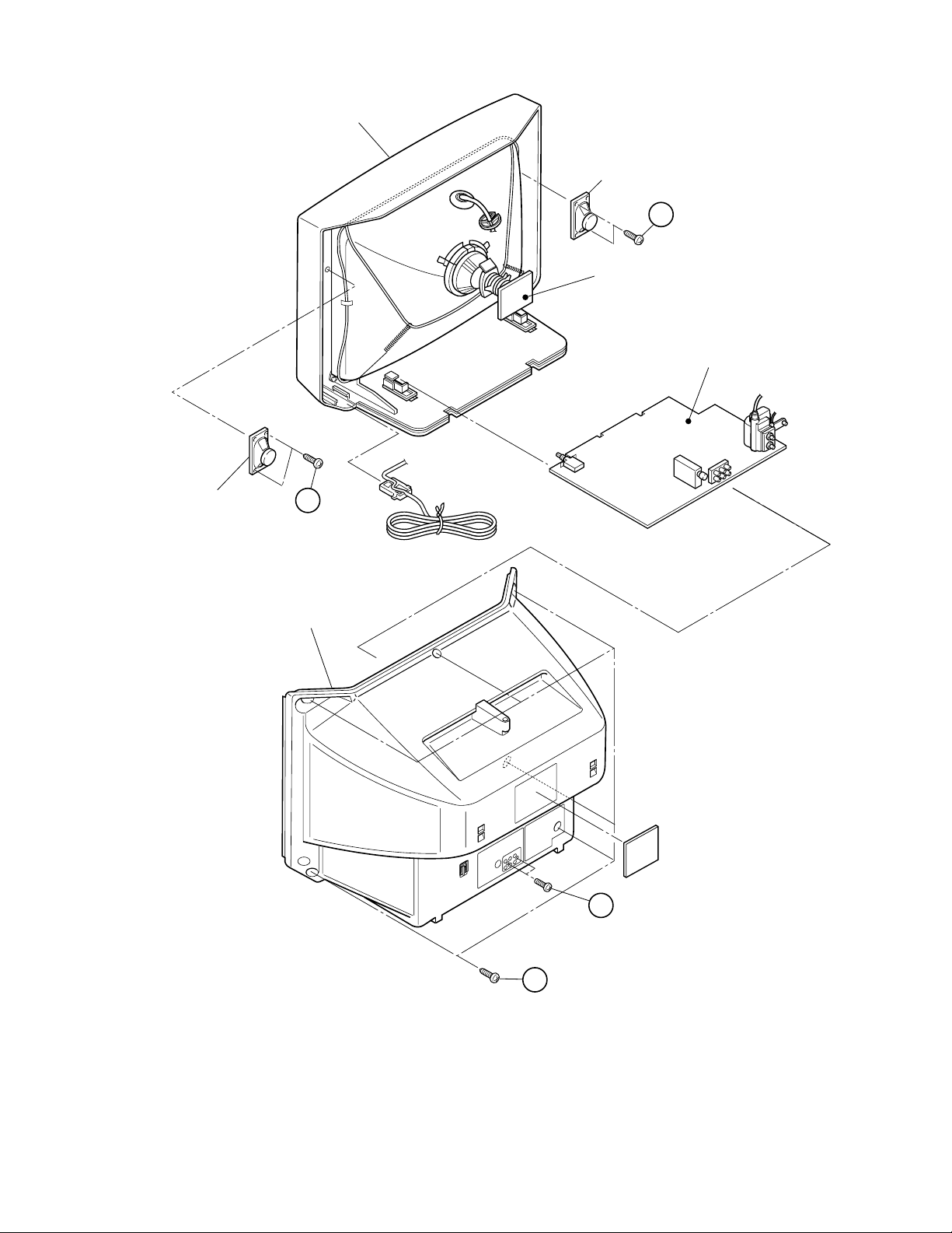
FRONT CABINET
SPEAKER
C
CRT SOCKET PWB
AV-21F8
(×2)
MAIN PWB
SPEAKER
(×2)
C
REAR COVER
B
(×2)
A
(×6)
No. 56036 5
Page 6
AV-21F8
SYSTEM CONSTANT - I
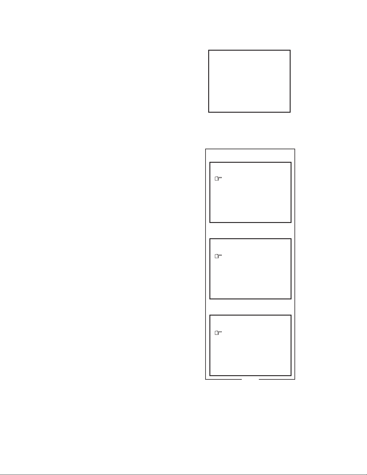
SYSTEM CONSTANT SET 1/3
SYSTEM CONSTANT - II
SYSTEM CONSTANT SET 2/3
− / + : OPERATE
DISP : EXIT
− / + : OPERATE
DISP : EXIT
11. LANGUAGE : E/V
12. TUNER : MU
13. AMP TUNER : YES
14. VNR : NO
SYSTEM CONSTANT - III
SYSTEM CONSTANT SET 3/3
− / + : OPERATE
DISP : EXIT
Fig. 2
a: SELECT
a: SELECT
a: SELECT
6. SPATIALIZER : YES
7. VOL. LIMITER : YES
8. B/B SOUND : NO
9. TEXT : NO
10. COLOUR AUTO : NO
1. INCH : 21
2. COLOUR : MULTI
3. VIDEO INPUT : 1
4. ECO SENSOR : YES
5. SUPER BASS : NO
REPLACEMENT OF MEMORY IC
1. MEMORY IC
This TV uses the following memory IC.
Memory IC: IC1702 on MAIN PW Board
The memory IC memorizes data for correctly operating the
video and deflection circuits. When replacing the memory IC,
be sure to use the same type IC written with the initial values
of data. In other words, use the specific IC listed in "PRINTED
WIRING BOARD PARTS LIST". For its mounting location, refer to "ADJUSTMENT LOCATIONS".
2. PROCEDURE FOR REPLACING MEMORY IC
(1) Power off
Switch the power off and unplug the power cord from the
wall outlet.
(2) Replacing the memory IC
Replace the memory IC with new one. Be sure to use the
memory IC written with the initial data values.
(3) Power on
Plug the power cord into the wall outlet and switch the
power on.
(4) Check and setting of SYSTEM CONSTANT SET:
1) Press the DISPLAY key and the PICTURE MODE key
on the remote control unit simultaneously.
The SERVICE MENU screen will be displayed. (See
Fig. 1.)
2) In the SERVICE MENU, press the DISPLAY key and
PICTURE MODE key simultaneously. Then, the SYSTEM CONSTANT SET screen will be displayed. (See
Fig. 2.)
3) Check whether the setting values of the SYSTEM CONSTANT SET are the same as those indicated in Table
1. If the value is different, select the setting item with
the MENU a key, and set the correct value with
the MENU − / + key.
4) Press the DISPLAY key twice to return to the normal
screen.
(5) Receive channel setting
Refer to the OPERATING INSTRUCTIONS and set the
receive channels (channels preset).
(6) User setting
Check the user setting values in Table 2, and if setting
value is different, set the correct value.
For setting, refer to the OPERATING INSTRUCTIONS.
(7) Setting of SERVICE MENU
Verify the setting for each setting item in the SERVICE
MENU. (See Table 3.) If readjustment is necessary, perform adjustment referring to "SERVICE ADJUSTMENTS".
SERVICE MENU
SERVICE MENU
1. IF
3. VSM PRESET
1-3 : SELECT DISP : EXIT
✽✽✽✽✽✽✽✽ ✽✽✽✽✽
2. V/C
✽✽.✽✽✽✽
✽✽✽ ✽✽✽✽✽
Fig. 1
✽✽.✽✽✽✽
No. 560366
Page 7
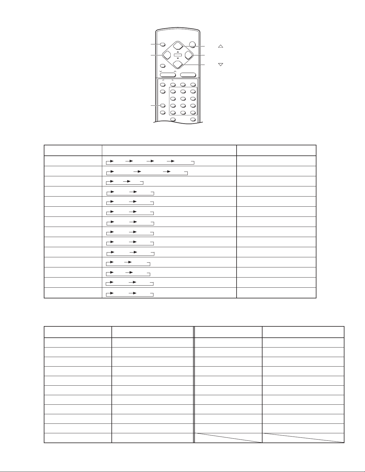
NAME OF REMOTE CONTROL KEYS
DISPLAY
MENU
PICTURE
MODE
AV-21F8
DISPLAY
−
LIVE
SPATIAL
CHANNEL
SYSTEM
COLOUR
SOUND
TV/VIDEO
PICTURE MODE
RETURN+
CHANNEL SCAN
ECO SENSOR OFF TIMER
POWER
+
−
MENU
−
+
VOLUME
PICTURE
MUTING
BOOSTER
123
456
7809
MENU
+
MENU
MENU
-/--
SETTING OF SYSTEM CONSTANT SET
Table 1
Setting item Setting contents Setting value
1. INCH 21
2. COLOUR MULTI
3. VIDEO INPUT 1
4. ECO SENSOR YES
5. SUPER BASS NO
6. SPATIALIZER YES
7. VOL. LIMITER YES
8. B/B SOUND NO
9. TEXT NO
10. COLOUR AUTO NO
11. LANGUAGE E/V
12. TUNER MU
13. AMP TUNER YES
14. VNR NO
29 25 21 14
MULTI. TRIPLE PAL
13
YES NO
YES NO
YES NO
YES NO
YES NO
YES NO
YES NO
E E/V
MU MA
YES NO
YES NO
RM-C234 REMOTE CONTROL UNIT
USER SETTING VALUES
Table 2
Setting item Setting value Setting item Setting value
SUB POWER ON BASS CENTER
CHANNEL POSITION 1 POSITION BALANCE CENTER
CHANNEL PRESET Refer to OPERATING INSTRUCTION. OFF TIMER OFF
VOLUME Appropriate sound volume AUTO SHUTOFF OFF
TV/VIDEO TV ECO SENSOR OFF
ON SCREEN DISPLAY POSITION NUMBER DISPLAY LANGUAGE VIETNAMESE
COLOUR SYSTEM PAL BLUE BACK OFF
SOUND SYSTEM B / G ON TIMER PR1 0:00
PICTURE MODE (VSM) BRIGHT CHILD LOCK OFF
LIVE SPATIAL OFF PICTURE BOOSTER OFF
TREBLE CENTER
No. 56036 7
Page 8

AV-21F8
SERVICE MENU SETTING ITEMS
Table 3
Service menu Setting item
1. IF 1. VCO
2. DELAY POINT
2. V / C 1. CUTOFF(R/G/B)
2. DRIVE(R/B)
3. BRIGHT
4. CONT.
5. COLOUR
6. TINT (TV/VIDEO)
7. BLACK OFFSET(R-Y/B-Y)
8. SHARP
9. TEXT(RGB)CONT.
10. H. CENTER
11. V. HEIGHT
12. V. LIN
13. V.S-CR
14. V. CENTER
15. AMP T . SHARP
Do not adjust.
Service menu Setting item
3. VSM PRESET TINT
(BRIGHT/STD/SOFT) COLOUR
BRIGHT
CONT.
SHARP
Do not adjust.
No. 560368
Page 9
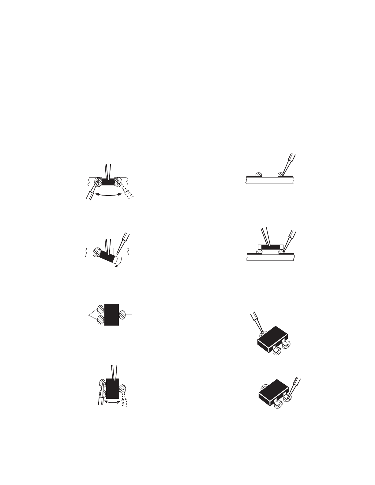
REPLACEMENT OF CHIP COMPONENT
■ CAUTIONS
1. Avoid heating for more than 3 seconds.
2. Do not rub the electrodes and the resist parts of the pattern.
3. When removing a chip part, melt the solder adequately.
4. Do not reuse a chip part after removing it.
■ SOLDERING IRON
1. Use a high insulation soldering iron with a thin pointed end
of it.
2. A 30W soldering iron is recommended for easily removing
parts.
■ REPLACEMENT STEPS
1. How to remove Chip parts
● Resistors, capacitors, etc.
(1) As shown in the figure, while pushing the chip part with twee-
zers, alternately melt the solder at its each end.
AV-21F8
2. How to install Chip parts
● Resistors, capacitors, etc.
(1) Apply solder to the pattern as indicated in the figure.
(2) Shift the chip part with tweezers and remove it.
● Transistors, diodes, variable resistors, etc.
(1) Apply extra solder to each lead.
SOLDER
(2) As shown in the figure, while pushing the chip part with twee-
zers, alternately melt the solder at its each lead. Then, shift
and remove the chip part.
SOLDER
(2) Grasp the chip part with tweezers and place it on the solder.
Then heat and melt the solder at both ends of the chip part.
● Transistors, diodes, variable resistors, etc.
(1) Apply solder to the pattern as indicated in the figure.
(2) Grasp the chip part with tweezers and place it on the solder.
(3) First solder lead A as indicated in the figure.
A
B
C
(4) Then solder leads B and C.
A
Note : After removing the part, remove remaining solder from
the pattern.
No. 56036 9
B
C
Page 10
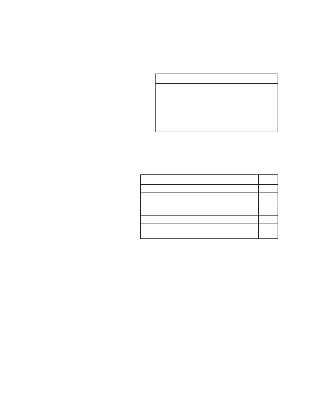
AV-21F8
SERVICE ADJUSTMENTS
BEFORE STARTING SERVICE ADJUSTMENT
1. There are 2 ways for adjusting this TV: One is with the
REMOTE CONTROL UNIT and the other is the conventional
method using adjustment parts and components.
2. The setting (adjustment) using the REMOTE CONTROL
UNIT is made on the basis of the initial setting values. The
setting values which adjust the screen to the optimum condition can be different from the initial setting values.
3. Make sure that connection is correctly made to AC power source.
4. Turn on the power of the TV and measuring instrument for warming up for at least 30 minutes before starting adjustment.
5. If the receive or input signal is not specified, use the most appropriate signal for adjustment.
6. Never touch parts (such as variable resistors, transformers and
capacitors) not shown in the adjustment items of this service
adjustment.
7. Preparation for adjustment (presetting):
Unless otherwise specified in the adjustment items, preset the
following functions with the remote control unit.
PICTURE MODE (VSM)
COLOUR/BRIGHT/CONT./SHARP
OFF TIMER
ECO SENSOR
BLUE BACK
PICTURE BOOSTER
Function
Setting value
BRIGHT
See "VSM Preset"
on page 23.
OFF
OFF
OFF
OFF
MEASURING INSTRUMENT
ADJUSTMENT/CHECK ITEMS
AND FIXTURES
Adjustment/Check item Page
1. DC voltmeter (or Digital voltmeter)
2. Oscilloscope
3. Signal generator (Pattern generator)
[PAL / SECAM / NTSC]
4. Remote control unit
B1 POWER SUPPLY Check 14
FOCUS Adjustment 14
IF CIRCUIT Adjustment 14
V/C (VIDEO/CHROMA) CIRCUIT Adjustment 15
DEFLECTION CIRCUIT Adjustment 21
VSM PRESET Adjustment 23
PURITY, CONVERGENCE Adjustment 24
BASIC OPERATION IN SERVICE MENU
1. TOOL OF SERVICE MENU OPERATION
Operate the SERVICE MENU with the remote control unit.
2. SERVICE MENU ITEMS
With the SERVICE MENU, various settings (adjustments) can be made, and they are broadly classified in the following items of settings:
● 1. IF ............................. For entering/adjusting the setting values (adjustment values) of the IF circuit.
● 2. V/C........................... For entering/adjusting the setting values (adjustment values) of the VIDEO/CHROMA and DEFLECTION cir-
● 3. VSM PRESET ......... For setting the values of STANDARD, SOFT and BRIGHT
cuits.
(VSM: video status memory)
No. 5603610
Page 11
AV-21F8
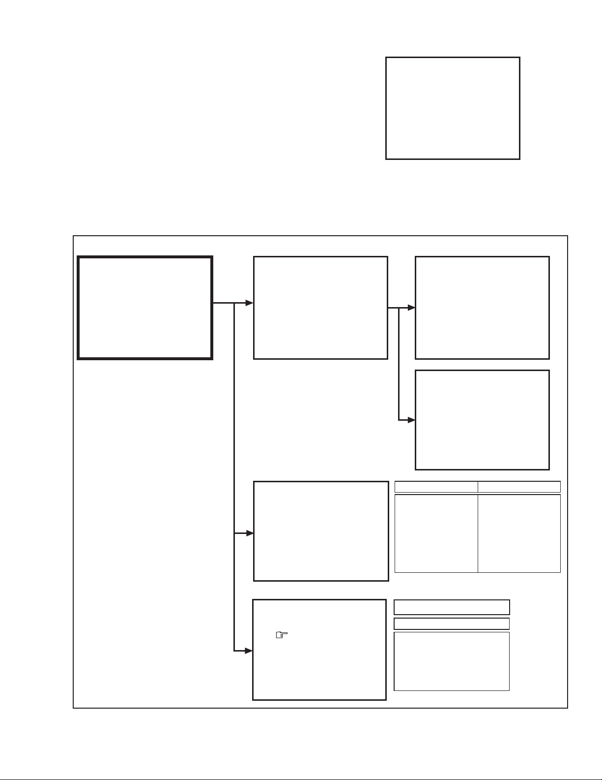
3. BASIC OPERATION IN SERVICE MENU
(1) How to enter SERVICE MENU
Press the DISPLAY key and the PICTURE MODE key on
the remote control unit simultaneously.
The SERVICE MENU screen will be displayed. (See Fig. 1.)
(2) Selection of SUB MENU SCREEN
Press one of the keys 1 ~ 3 on the remote control unit, and
select the SUB MENU SCREEN from the SERVICE MENU.
(See Fig. 2.)
SERVICE MENU → SUB MENU 1. IF
2. V / C
3. VSM PRESET
SUB MENU SCREEN
SERVICE MENU
SERVICE MENU
1. IF
3. VSM PRESET
1-3 : SELECT DISP : EXIT
✽✽✽✽✽✽✽✽ ✽✽✽✽✽
✽✽✽ ✽✽✽✽✽
2. V/C
✽✽.✽✽✽✽
✽✽.✽✽✽✽
SUB MENU 1. IF
IF
1. VCO
2. DELAY POINT
1-2 : SELECT DISP : EXIT
SERVICE MENU
SERVICE MENU
1. IF
3. VSM PRESET
1-3 : SELECT DISP : EXIT
✽✽✽✽✽✽✽✽ ✽✽✽✽✽
2. V/C
✽✽.✽✽✽✽
✽✽✽ ✽✽✽✽✽
Fig. 1
VCO (CW)
TOO HIGH
ABOVE REFERENCE
BELOW REFERENCE
TOO LOW
✽✽.✽✽✽✽
✽✽✽.✽✽ MHz
DISP : EXIT
SUB MENU 2. V/C
V/C
1. CUTOFF
50Hz
a : SELECT
− / + : OPERATE
PAL
(R)
✽ ✽✽
(G)
✽ ✽✽
✽ ✽✽
(B)
DISP : EXIT
SUB MENU 3. VSM PRESET
BRIGHT
TINT
COLOUR
BRIGHT
CONT.
SHARP
a : SELECT
− / + : OPERATE
✽✽
✽✽
✽✽
✽✽
✽✽
DISP : EXIT
DELAY POINT
AGC TAKE-OVER
− / + : OPERATE
Setting item
1. CUTOFF(R/G/B)
2. DRIVE(R/B)
3. BRIGHT
4. CONT.
5. COLOUR
6. TINT (TV/VIDEO)
7. BLACK OFFSET(R-Y/B-Y)
8. SHARP
9. TEXT(RGB)CONT.
BRIGHT / STD / SOFT
Setting item
TINT
COLOUR
BRIGHT
CONT.
SHARP
✽✽
DISP : EXIT
Setting item
10. H. CENTER
11. V. HEIGHT
12. V. LIN
13. V.S-CR
14. V. CENTER
15. AMP T. SHARP
Fig. 2
No. 56036 11
Page 12

AV-21F8
(3) Method of Setting
*Once the setting values are set, they are memorized automatically.
*It must not adjust without inputting a signal.
1) 1. IF
[1. VCO]
(a) 1 Key ......................................... Select 1. IF.
(b) 1 Key ......................................... Select 1. VCO. (CW)
(c) VCO(CW) TRANSF. .................. Adjust VCO(CW) while watching the colour (yellow/blue) of the characters on the screen.
(d) DISPLAY Key ............................ When this is pressed twice, you will return to the SERVICE MENU.
[2. DELAY POINT]
(a) 1 Key ......................................... Select 1. IF.
(b) 2 Key ......................................... Select 2. DELAY POINT.
(c) MENU − / + Key......................... Adjust the setting value.
(d) DISPLAY Key ............................ When this is pressed twice, you will return to the SERVICE MENU.
2) 2. V/C and 3. VSM PRESET
(a) 2 and 3 Keys ............................. Select 2. V/C and 3. VSM PRESET.
(b) MENU a key........................ Select setting items.
(c) MENU − / + Key......................... Adjust the setting values of the setting items.
● Use the number keys on the remote control unit for setting of WHITE BALANCE and BLACK
(d) DISPLAY Key ............................ When this is pressed, you will return to the SERVICE MENU.
OFFSET. For the setting, refer to each item concerned.
(4) Release of SERVICE MENU
After completing the setting, return to the SERVICE MENU by pressing the DISPLA Y key, then again press the DISPLAY key to return
to the normal screen.
No. 5603612
Page 13
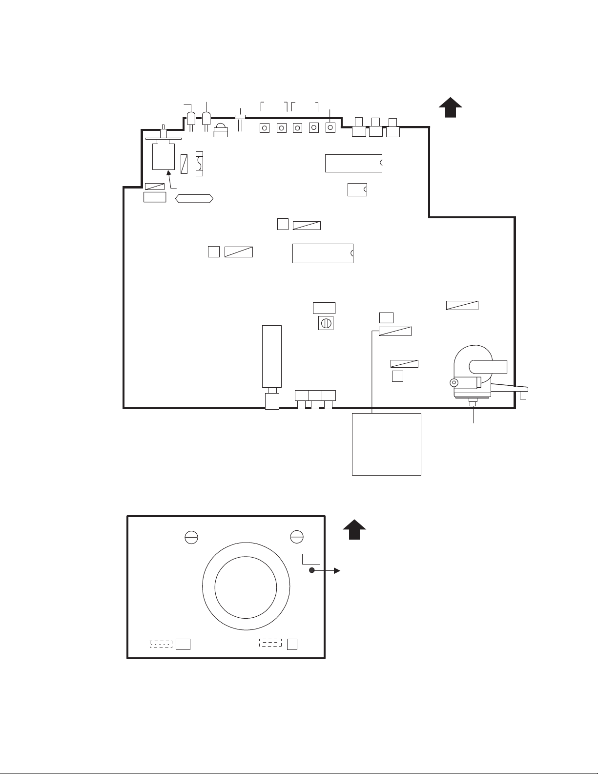
ADJUSTMENT LOCATIONS
MAIN PWB
ON
TIMER
POWER
ECO
SENSOR
VOL-+CH
-
+
AV-21F8
FRONT
MENU
DEG
PW
S901
POWER SW
REMOCON
RECEIVER
F901
S
TU001
IC701
MEMORY
IC
IC702
T
28
1
IC201
29
56
HV
VCO
T101
S1
15
HVT
U
CRT SOCKET PWB
(SOLDER SIDE)
TP-47G
T
TP-E
U
1 Pin TP-91(B1)
2 Pin NC
3 Pin X-ray1
4 Pin X-ray2
5 Pin TP-E
TOP
E
1
(")
UPPER : FOCUS
LOWER : SCREEN
CRT EARTH
(BRAIDED ASS'Y)
No. 56036 13
Page 14
AV-21F8
ADJUSTMENTS
B1 POWER SUPPLY
Item Test point Adjustment part
Measuring
instrument
Check of Signal TP-91 (B1)
B1 POWER Generator TP-E (
""
")
""
SUPPLY [S1
DC Voltmeter connector]
FOCUS ADJUSTMENT
Item Test point Adjustment part
Adjustment Signal FOCUS VR
of FOCUS generator [In HVT]
Measuring
instrument
IF CIRCUIT ADJUSTMENT
Description
1. Receive a whole black signal.
2. Connect a DC voltmeter between TP-91 (B1) and TP-E (")
(between pins 1 and 5 of the connector S1).
3. Make sure that the voltage is DC114.5 ± 1.5V.
Description
1. Receive a cross-hatch signal.
2. While watching the screen, adjust the FOCUS VR to make the
vertical and horizontal lines as fine and sharp as possible.
3. Make sure that, when the screen is darkened, the lines remain
in good focus.
Item Test point Adjustment part
Measuring
instrument
Adjustment Remote VCO (CW)
of VCO (CW) control unit TRANSF.
[MAIN PWB]
fv
YELLOW
Screen display
VCO (CW) ✽✽✽.✽✽ MHz
TOO HIGH
ABOVE REFERENCE
BELOW REFERENCE
TOO LOW
DISP : EXIT
Step
123
TOO HIGH Yellow Blue Blue
ABOVE REFERENCE Blue Yellow Blue
BELOW REFERENCE Blue Blue Yellow
TOO LOW Blue Blue
Description
● Under normal conditions, no adjustment is required.
1. Select 1. IF from the SERVICE MENU.
2. Press the 1 key to select 1. VCO.
3. Select a receivable broadcast channel with the CHANNEL key .
4. Turn the core of VCO(CW) TRANSF. until the colour of the
characters "TOO HIGH" displayed on the screen changes from
blue to yellow. (Step 1)
5. Then slowly turn the core of VCO(CW) TRANSF . counterclockwise until the characters "ABOVE REFERENCE" changes from
blue to yellow. (Step 2)
6. Further slowly turn the core of VCO(CW) TRANSF. until the
colour of the characters "BELOW REFERENCE" changes from
blue to yellow. (Step 3)
7. Press the DISPLAY key three times to return to normal screen.
8. Perform CHANNEL PRESET again, and make sure that each
broadcast is being received properly.
No. 5603614
Page 15
AV-21F8
Item Test point Adjustment part
Adjustment Remote DELAY POINT
of DELAY control unit (AGC TAKE-OVER)
POINT
Setting
(Adjustment)
item
DELAY POINT
(AGC TAKE-OVER)
Measuring
instrument
Variable Initial setting
range value
0 ~ 63 20
Description
1. Receive a black and white signal (colour off).
2. Select 1. IF from the SERVICE MENU.
3. Select 2. DELAY POINT by pressing the 2 key on the remote
control.
4. Adjust the MENU − or + key until video noise disappears.
5. Press the DISPLAY key three times to return to the normal
screen.
6. Turn to other channels and make sure that there are no irregularities.
V/C (VIDEO/CHROMA) CIRCUIT ADJUSTMENT
The setting (adjustment) using the remote control unit is made on the basis of the initial setting values.
The setting values which adjust the screen to the optimum condition can be different from the initial setting values.
● Do not change the initial setting values of the setting (adjustment) items not listed in "ADJUSTMENT".
[SUB MENU 2. V/C (1. CUT OFF (R / G / B) ~ 9. TEXT (RGB) CONT. and 15. AMP SHARP)]
Colour system Variable Initial setting value
Setting item range PAL SECAM NTSC 3.58 NTSC 4.43
1. CUT OFF (R / G / B) −128 ~ +127 0 b b b
2. DRIVE (R / B) −128 ~ +127 0 b b b
3. BRIGHT −64 ~ +63 −11 b b b
4. CONT. −58 ~ +28 −10 b b b
5. COLOUR −60 ~ +67 +7 +11 +12 −2
6. TINT TV / VIDEO −64 ~ +63 +5 / 0 −2 / 0
7. BLACK OFFSET (R-Y / B-Y) −8 ~ +7 0 / 0
8. SHARP TV / VIDEO −32 ~ +31 +10 / +8 b b b
9. TEXT (RGB) CONT. −128 ~ +127 +15 b b b
15. AMP T. SHARP −128 ~ +127 −15 b b b
: Do not adjust.
No. 56036 15
Page 16

AV-21F8
Item Test point Adjustment part
Measuring
instrument
Adjustment ● Signal 1. CUTOFF (R)
of WHITE generator CUTOFF (G)
BALANCE CUTOFF (B)
(Low light) ● Remote
control SCREEN VR
unit (In HVT)
V/C
1. CUTOFF
50Hz
a : SELECT
− / + : OPERATE
PAL
(R)
✽ ✽✽
(G)
✽ ✽✽
(B)
✽ ✽✽
DISP : EXIT
REMOTE CONTROL UNIT
H.LINE OFF
12 3
H.LINE ON
G. CUTOFF ( )
B. CUTOFF ( )
B. DRIVE ( )
B. CUTOFF ( )
B. DRIVE ( )
G. CUTOFF ( )
R. CUTOFF ( )
R. DRIVE ( )
R. CUTOFF ( )
R. DRIVE ( )
4
789
56
Description
1. Receive a black and white signal (colour off).
2. Select 2. V/C from the SERVICE MENU.
3. Select 1. CUTOFF (R), (G) and (B) with MENU a key, and
set each value to initial setting value with 4 ~ 9 keys on the
remote control unit.
4. Press the 1 key on the remote control unit to produce a single
horizontal line.
5. Turn the SCREEN VR fully counterclockwise, then slowly turn
it clockwise to where a red, blue, or green colour is faintly visible.
6. Use keys 4 ~ 9 on the remote control unit and adjust the other
2 colours to where the single horizontal line appears white.
7. Turn the SCREEN VR to where the single horizontal line glows
faintly.
8. Press the 2 key to return to 1. CUTOFF screen.
9. Press the DISPLAY key twice to return to the normal screen.
Setting (Adjustment) Variable Initial setting
item range value
R −128 ~ +127 0
1. CUT OFF G −128 ~ +127 0
B −128 ~ +127 0
Adjustment ● Signal 2. DRIVE (R)
of WHITE generator DRIVE (B)
BALANCE
(High light) ● Remote
control
unit
V/C
2. DRIVE
50Hz
a : SELECT
− / + : OPERATE
PAL
✽ ✽✽
(R)
(B)
✽ ✽✽
DISP : EXIT
1. Receive a black and white signal (colour off).
2. Select 2. V/C from the SERVICE MENU.
3. Select 2. DRIVE (R) / (B) with MENU a key, and set each
value to initial setting value with 4 and 7 keys, or 6 and 9 keys
on the remote control unit.
4. Use the keys 4 and 7 or 6 and 9 to produce a white screen.
5. Press the DISPLAY key twice to return to the normal screen.
Setting (Adjustment) Variable Initial setting
item range value
R −128 ~ +127 0
2. DRIVE
B −128 ~ +127 0
No. 5603616
Page 17

AV-21F8
Item Test point Adjustment part
Adjustment Remote 3. BRIGHT
of control unit
SUB
BRIGHT
Adjustment Remote 4. CONT.
of control unit
SUB CONT.
Adjustment Remote 5. COLOR
of control unit
SUB
COLOUR-I PAL COLOUR
Measuring
instrument
Description
1. Receive any broadcast.
2. Select 2. V/C from the SERVICE MENU.
3. Select 3. BRIGHT with the MENU a key.
4. Set the initial setting value with the MENU − or + key.
5. If the brightness is not the best with the initial set value, make
fine adjustment until you get the best brightness.
6. Press the DISPLAY key twice to return to the normal screen.
1. Receive any broadcast.
2. Select 2. V/C from the SERVICE MENU.
3. Select 4. CONT. with the MENU a key.
4. Set the initial setting value with the MENU − or + key.
5. If the contrast is not the best with the initial set value, make
fine adjustment until you get the best contrast.
6. Press the DISPLAY key twice to return to the normal screen.
[Method of adjustment without measuring instrument]
(PAL COLOUR)
1. Receive a PAL broadcast.
2. Select 2. V/C from the SERVICE MENU.
3. Select 5. COLOUR with the MENU a key.
4. Set the initial setting value for PAL COLOUR with the MENU
− or + key.
5. If the colour is not the best with the initial set value, make fine
adjustment until you get the best colour.
6. Press the DISPLAY key twice to return to the normal screen.
SECAM COLOUR
NTSC 3.58 COLOUR
(SECAM COLOUR)
1. Receive a SECAM broadcast.
2. Make fine adjustment of SECAM COLOUR in the same way
as for "PAL COLOUR".
(NTSC 3.58 COLOUR)
1. Receive a NTSC 3.58MHz broadcast.
2. Make similar fine adjustment of NTSC 3.58 COLOUR in the
same way as for "PAL COLOUR".
(NTSC 4.43 COLOUR)
When adjustment is done for NTSC 3.58 COLOUR, appropriate
values are automatically set for NTSC 4.43 COLOUR.
No. 56036 17
Page 18

AV-21F8
Item Test point Adjustment part
Measuring
instrument
Adjustment ● Signal TP-47G 5. COLOUR
of SUB generator TP-E (
""
")
""
COLOUR-II [CRT
● Oscillo- SOCKET PAL COLOUR
scope PWB]
● Remote
control
unit
B
Mg
R
(A)
Cy
Y
W
G
(−)
0V
(+)
SECAM COLOUR
Description
[Method of adjustment using measuring instrument]
(PAL COLOUR)
1. Receive a PAL full field colour bar signal (75% white).
2. Select 2. V/C from the SERVICE MENU.
3. Select 5. COLOUR with the MENU a key.
4. Set the initial setting value of PAL COLOUR with the MENU
− or + key.
5. Connect the oscilloscope between TP-47G and TP-E.
6. Adjust PAL COLOUR to set the value (A) in the figure to +5V
(W & G).
(SECAM COLOUR)
1. Receive a SECAM full field colour bar signal (75% white).
2. Set the initial setting value of SECAM COLOUR with the MENU
− or + key.
3. Adjust SECAM COLOUR to set the value (A) in the figure to
+4V (W & G).
NTSC 3.58 COLOUR
No. 5603618
(NTSC 3.58 COLOUR)
1. Receive a NTSC 3.58 full field colour bar signal (75% white).
2. Set the initial setting value of NTSC 3.58 COLOUR with the
MENU − or + key.
3. Adjust NTSC 3.58 COLOUR to set the value (A) in the figure
to +3V (W & G).
(NTSC 4.43 COLOUR)
When adjustment is done for NTSC 3.58 COLOUR, appropriate
values are automatically set for NTSC 4.43 COLOUR.
Page 19

AV-21F8
Item Test point Adjustment part
Measuring
instrument
Adjustment Remote 6. TINT
of control unit
SUB TINT-I
NTSC 3.58 TINT
Description
[Method of adjustment without measuring instrument]
(NTSC 3.58 TINT)
1. Receive a NTSC 3.58 colour bar signal (full field colour bar
75% white).
2. Select 2. V/C from the SERVICE MENU.
3. Select 6. TINT with the MENU a key.
4. Set the initial setting value of NTSC 3.58 with the MENU − or
+ key.
5. If you cannot get the best tint with the initial setting value,
make fine adjustment until you get the best tint.
6. Press the DISPLAY key twice to return to the normal screen.
(NTSC 4.43 COLOUR)
When adjustment is done for NTSC 3.58 TINT, appropriate values are automatically set for NTSC 4.43 TINT.
Adjustment ● Signal TP-47G 6. TINT
of generator TP-E (
""
")
""
SUB TINT-II [CRT
● Oscillo- SOCKET
scope PWB] NTSC 3.58 TINT
● Remote
control
unit
B
Mg
R
(B)
Cy
W
G
Y
(−)
0V
(+)
[Method of adjustment using measuring instrument]
(NTSC 3.58 TINT)
1. Receive a NTSC 3.58 colour bar signal (full field colour bar
75% white).
2. Select 2. V/C from the SERVICE MENU.
3. Select 6. TINT with the MENU a key.
4. Set the initial setting value of NTSC 3.58 with the MENU − or
+ key.
5. Connect the oscilloscope between TP-47G and TP-E.
6. Adjust NTSC 3.58 TINT to set the value (B) in the figure to
+3V (W & Cy).
7. Press the DISPLAY key twice to return to the normal screen.
(NTSC 4.43 TINT)
When adjustment is done for NTSC 3.58 TINT, appropriate values are automatically set for NTSC 4.43 TINT.
No. 56036 19
Page 20

AV-21F8
Item Test point Adjustment part
Measuring
instrument
Adjustment Remote
of BLACK control unit
OFFSET-I
(SECAM) 7. BLACK OFFSET
(R-Y)
(B-Y)
REMOTE CONTROL UNIT
BLACK &
WHITE OFF
BLACK &
WHITE ON
R-Y ( )
R-Y ( )
12 3
4
789
56
B-Y ( )
B-Y ( )
Adjustment ● Signal 35 PIN (R-Y)
of BLACK generator 36 PIN (B-Y)
OFFSET-II IC 201 on
(SECAM) ● Oscillo- MAIN PWB 7. BLACK OFFSET
scope (R-Y)
(B-Y)
● Remote
control
unit
[R-Y]
Flat Flat
(b)(a)
Description
[Method of adjustment without measuring instrument]
1. Receive a SECAM broadcast.
2. Select 2. V/C from the SERVICE MENU.
3. Select 7. BLACK OFFSET with the MENU a key.
4. Set the initial setting value for BLACK OFFSET (R-Y) and (BY) with 4 and 7 or 6 and 9 keys on the remote control unit.
5. If the picture is not the best with the initial setting value, make
fine adjustment until you get the best picture.
6. Press the DISPLAY key twice to return to the normal screen.
[Method of adjustment using measuring instrument]
1. Receive a SECAM COLOUR bar signal (full field colour bar
75% white).
2. Select 2. V/C from the SERVICE MENU.
3. Select 7. BLACK OFFSET with the a key.
4. Connect the oscilloscope between pin 35 of IC 201 and TP-E.
5. By using 4 and 7 keys on the remote control unit, adjust the
BLACK OFFSET (R-Y) so that the waveform changes from
(a) to (b) as shown in the figure.
6. Connect the oscilloscope between pin 36 of IC 201 and TP-E.
7. By using 6 and 9 keys on the remote control unit, adjust the
BLACK OFFSET (B-Y) so that the waveform changes from
(c) to (d) as shown in the figure.
8. If the picture is not the best with the adjusted picture, make
fine adjustment until you get the best picture.
9. Press the DISPLAY key twice to return to the normal screen.
[B-Y]
Flat
(c) (d)
Flat
No. 5603620
Page 21

DEFLECTION CIRCUIT ADJUSTMENT
● There are 2 modes of adjustment (initial setting value) — 50Hz mode and 60Hz mode — depending upon the kind of signals (vertical
frequency 50Hz / 60Hz).
● When adjusted in 50Hz mode, 60Hz mode will be automatically set.
The setting (adjustment) using the remote control unit is made on the basis of the initial setting values.
The setting values which adjust the screen to the optimum condition can be different from the initial setting values.
[SUB MENU 2. V/C (10. H. CENTER ~ 14. V. CENTER)]
AV-21F8
Setting item Adjustment name Variable range
Initial setting value
50Hz 60Hz
10. H. CENTER Horizontal center −16 ~ +15 −10 −10
11. V. HEIGHT Vertical height −64 ~ +63 −15 0
12. V. LIN Vertical linearity −16 ~ +15 0 0
13. V.S-CR Vertical height correction −64 ~ +63 −15 0
14. V. CENTER Vertical center 0 ~ +127 0 (Fixed) 0 (Fixed)
: Do not adjust.
Item Test point Adjustment part
Measuring
instrument
Adjustment ● Signal 11. V. HEIGHT
of generator
V. HEIGHT
● Remote
control
unit
[ fv : 50Hz mode]
1. Receive a cross-hatch signal.
2. Select 2. V/C from the SERVICE MENU.
3. Select 11. V. HEIGHT with the MENU a key.
4. Set the initial setting value of 11. V. HEIGHT with the MENU −
/ + key.
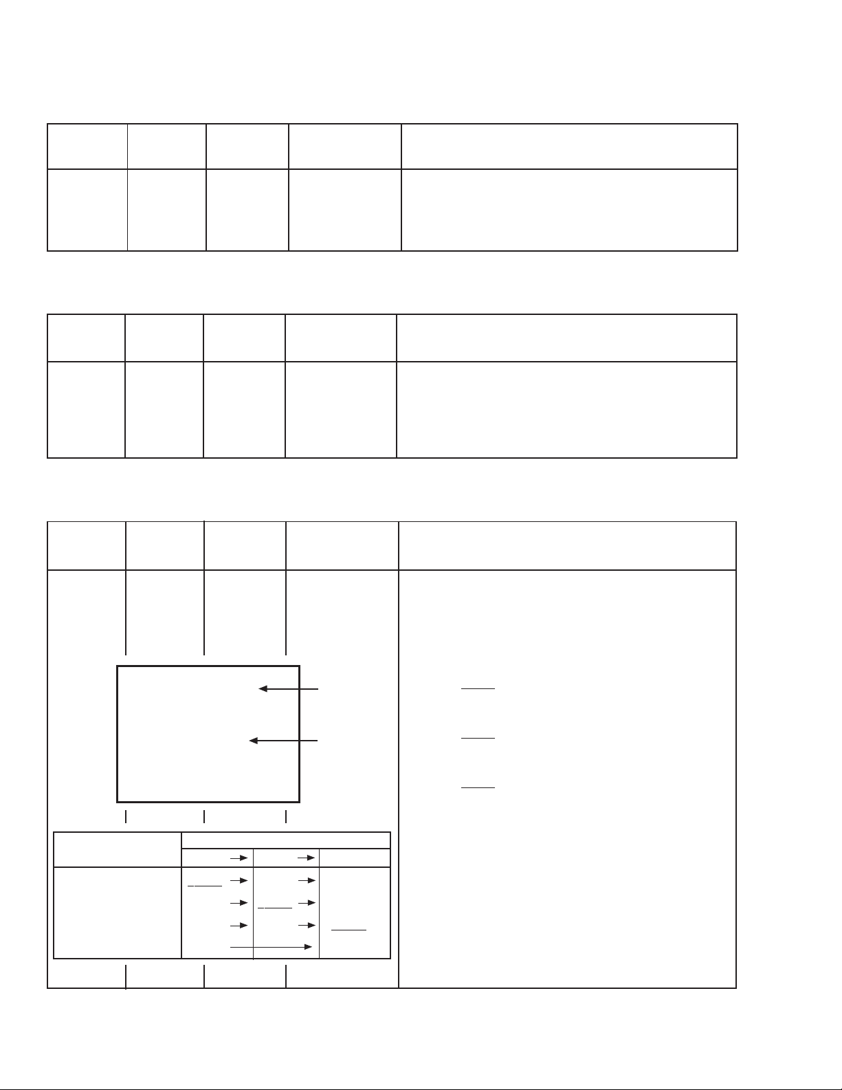
Description
5. Adjust V. HEIGHT and make the vertical screen size 92% of
Screen size
the picture size with the MENU − / + key.
Screen
size
92%
(to be continued)
Picture
size
100%
Picture size 100%
No. 56036 21
Page 22

AV-21F8
Item Test point Adjustment part
Measuring
instrument
Adjustment 10. H. CENTER
of
H. CENTER
AB
Adjustment 13. V.S-CR
of 12. V. LIN
V.S-CR &
V. LIN
TOP
CENTER
Description
6. Receive a circle pattern signal.
7. Select 10. H. CENTER with the MENU a key.
8. Set the initial setting value of 10. H. CENTER with the MENU
− / + key.
9. Adjust H. CENTER to make "A = B" with the MENU − / + key.
● When the vertical linearity has been deteriorated remark-
ably, perform the following steps.
10. Receive a cross-hatch signal.
11. Select 13. V.S-CR with the MENU a key.
12. Set the initial setting value of 13. V.S-CR with the MENU − / +
key.
13. Select 12. V. LIN with the MENU a key.
14. Set the initial setting value of 12. V. LIN with the MENU − / +
key.
15. Adjust V.S-CR and V. LIN so that the spaces of each line on
TOP, CENTER and BOTTOM become uniform.
BOTTOM
16. Make sure that the adjustment is properly done on the screen
of 60Hz mode.
17. Press the DISPLAY key twice to return to the normal screen.
[NOTE]
● When adjust in 60Hz mode, only 60Hz mode is adjust.
No. 5603622
Page 23

VSM PRESET ADJUSTMENT
AV-21F8
Item Test point Adjustment part
Measuring
instrument
Setting of Remote TINT
VSM control unit COLOUR
PRESET BRIGHT
CONT.
SHARP
SUB MENU 3. VSM PRESET
BRIGHT
TINT
COLOUR
BRIGHT
CONT.
SHARP
a : SELECT
− / + : OPERATE
✽✽
✽✽
✽✽
✽✽
✽✽
DISP : EXIT
Description
(VSM PRESET)
1. Select 3. VSM PRESET from the SERVICE MENU.
2. Select BRIGHT with the PICTURE MODE key.
3. Adjust the MENU a key and MENU − or + key to reset the
set values of TINT ~ SHARP to the values shown in the table.
4. Respectively select the VSM PRESET mode for SOFT and
STANDARD, and make similar adjustment as in 3 above.
5. Press the DISPLAY key twice to return to the normal screen.
[Setting Values for SUB MENU 3. VSM PRESET]
VSM preset
VSM mode BRIGHT STANDARD SOFT
Setting item
TINT
SETTING VALUE
COLOUR
SETTING VALUE
BRIGHT
SETTING VALUE
CONT.
SETTING VALUE
SHARP
SETTING VALUE
15
15
15
30 19 11
15
bb
b
bb
bb
b
bb
bb
b
bb
bb
b 12
bb
bb
b
bb
bb
b
bb
bb
b
bb
: Do not adjust.
No. 56036 23
Page 24

AV-21F8
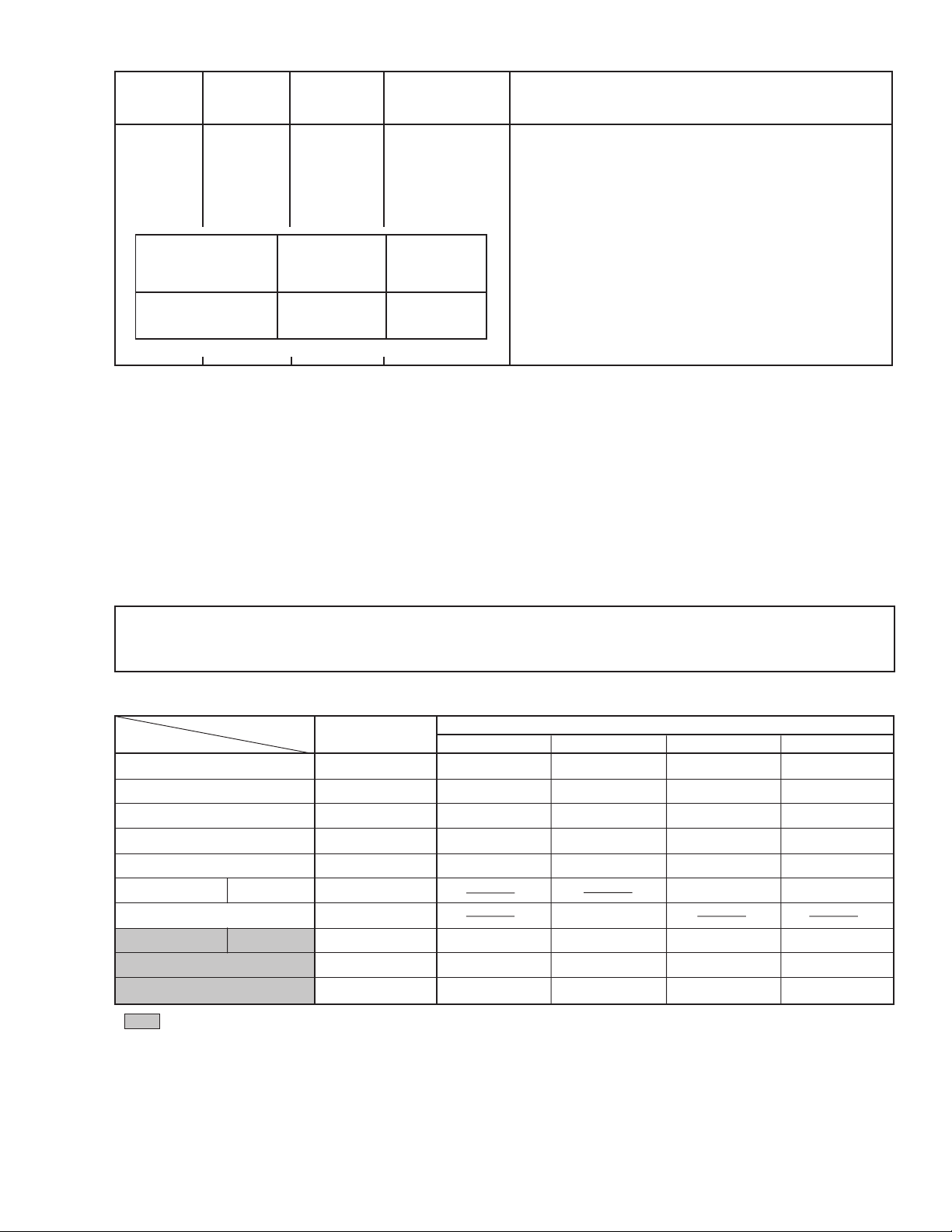
PURITY, CONVERGENCE ADJUSTMENT
Note: The picture tube includes the deflection yoke and purity magnets, and purity and convergence adjustments are precisely adjusted
at the factory.
PURITY ADJUSTMENT
1. Demagnetize CRT with the demagnetizer.
2. Loosen the retainer screw of the deflection yoke.
3. Remove the wedges. (Fig. 1.)
4. Input a green raster signal from the signal generator, and turn
the screen to green raster.
5. Move the deflection yoke backward.
6. Bring the long lug of the purity magnets on the short lug and
position them horizontally. (Fig. 2)
7. Adjust the gap between two lugs so that the green raster will
come into the center of the screen. (Fig. 3)
8. Move the deflection yoke forward, and fix the position of the
deflection yoke so that the whole screen will become green.
9. Insert the wedge to the top side of the deflection yoke so that it
will not move.
Long lug
CRT
WEDGE
P : PURITY MAGNET
4 : 4 POLES (convergence magnets)
6 : 6 POLES (convergence magnets)
DEFLECTION
YOKE
P
4 6
P/C
MAGNETS
• P/C MAGNETS
Fig. 1
PURITY MAGNETS
10. Input a cross-hatch signal.
11. Verify that the screen is horizontal.
12. Input red and blue raster signals, and make sure that purity is
properly adjusted.
Short lug
(FRONT VIEW)
Bring the long lug over the short lug
and position them horizontally.
Fig. 2
GREEN RASTER
CENTER
Fig. 3
No. 5603624
Page 25

STATIC CONVERGENCE ADJUSTMENT
1. Input a cross-hatch signal.
2. Using 4-pole convergence magnets, overlap the red and blue
lines in the center of the screen (Fig. 1) to turn them to magenta
(red/blue).
3. Using 6-pole convergence magnets, overlap the magenta (red/
blue) and green lines in the center of the screen to turn them to
white.
AV-21F8
(FRONT VIEW)
4. Repeat 2 and 3 above, and make best convergence.
DYNAMIC CONVERGENCE ADJUSTMENT
1. Move the deflection yoke up and down and overlap the lines in
the periphery. (Fig. 2)
2. Move the deflection yoke left to right and overlap the lines in the
periphery. (Fig. 3)
3. Repeat 1 and 2 above, and make best convergence.
● After adjustment, fix the wedge at the original position.
Fasten the retainer screw of the deflection yoke.
Fix the 6 magnets with glue.
(FRONT VIEW)
BLUE
GREEN
RED
(FRONT VIEW)
RED
RED GREEN BLUE
GREEN
BLUE
Fig. 1
GREEN
Fig. 2
REDBLUE
BLUE
GREEN
RED
GREEN
BLUE
RED
RED
GREEN
BLUE
BLUE
GREEN
RED
Fig. 3
No. 56036 25
Page 26

AV-21F8
SELF-CHECK FUNCTIONS
1. Outline
This model has self-check functions given below. When an abnormality has been detected, the SUB POWER is turned off and the ON
TIMER LED flashes to inform of the failure. An abnormality is detected by the signal input state of the control line connected to the
microcomputer.
2. Self-check items
Check item
Over-current protection
Details of detection
An over-current on the low B line
is detected.
CRT NECK protection
Operation of CRT NECK protection circuit
3. Self-check indicating function
At about 3 seconds after the power is turned on, the self-check
function starts.
In the case where an abnormality has been detected within
the subsequent 2 seconds, the ON TIMER LED flashes, but
the SUB-POWER will be turned on when the elapsed time after power on reaches 5 seconds.
When an abnormality has been detected at about 5 seconds
after power on, the ON TIMER LED flashes, and then the SUB
POWER will be turned off immediately.
Method of detection
The main microcomputer detects
the possible abnormality at 30msec. intervals and judges the results in every 16 time. Of the 16
times, if NG is detected more
than 9 times, it is judged that
there is an abnormality.
DITTO
After about
3 seconds
Power on
Start of
detection
State of abnormality
When an abnormality has been
detected, the SUB-POWER is
turned off. While the SUBPOWER is being turned off, the
POWER key on the remote control unit is not operational until the
power cord is taken out and put
in again.
DITTO
After about
5 seconds
Flashing LED
Detection of
an
abnormality
SUBPOWER
OFF
[ Indication by the LED ]
Item ON TIMER LED flashing intervals Priority of detection
① Over-current protection At 0.25-second intervals 1
➁ CRT NECK protection At 0.5-second intervals 2
Note: In case of ① + ➁, the item ① is indicated.
No. 5603626
Page 27

AV-21F8
VICTOR COMPANY OF JAPAN, LIMITED
TELEVISION RECEIVER DIVISION 1106 Heta, Iwai-city, Ibaraki-prefecture, 306-0698, Japan
No. 5603636
AV21F8VT-CK #3
CTH 0006
CRT
Page 28

OPERATING INSTRUCTIONS
2
Locations
Locations of remote control buttons
1
DISPLAY button p.18
2
MENU buttons
• MENU
/
buttons
• MENU –/+ buttons
3
LIVE SPATIAL button p.16
4
CHANNEL
/
buttons p.12
5
SOUND SYSTEM button p.15
6
COLOUR SYSTEM button p.15
7
TV/VIDEO button p.14
8
PICTURE MODE button p.15
9
CHANNEL SCAN button p.19
0
RETURN + button p.20
-
ECO SENSOR button p.19
=
POWER button p.6,12,13
~
VOLUME –/+ buttons p.13
!
PICTURE BOOSTER button p.17
@
MUTING button p.16
#
Number buttons p.12
$
-/-- button p.12
%
OFF TIMER button p.18
RM-C218 REMOTE CONTROL UNIT
DISPLAY
LIVE
SPATIAL
MENU
POWER
CHANNEL VOLUME
SYSTEM
COLOUR
OFF TIMER
TV/VIDEO
CHANNEL SCAN
ECO SENSOR
SOUND MUTING
RETURN
123
456
78
0
9
-/--
PICTURE MODE
BOOSTER
PICTURE
=
~
!
@
#
$
%
0
-
7
8
9
6
5
4
3
2
1
3
1
MENU buttons p.24
• MENU button
• MENU –/+ buttons
2
CHANNEL
/
buttons p.13
3
VOLUME –/+ buttons p.13
Locations
Locations of front panel buttons and lamps
4
ECO sensor
5
Remote control sensor
6
ON TIMER lamp p.21
7
POWER lamp p.6,13
8
Main power button p.6,13
MENU
CHANNEL
VOLUME
POWER
ON TIMER
EXIT
1
2
3
57
684
No. 56036
1-1
AV-21F8
Page 29

SCHEMATIC DIAGRAMS
COLOUR TELEVISION
AV-21F8(VT)
AV-21F8
AV-21F8
++−
−
COPYRIGHT 2000 VICTOR COMPANY OF JAPAN, LTD.
No. 56036 2-1
No. 56036
Jun. 2000
Page 30

AV-21F8
2-2 No. 56036
Page 31

STANDARD CIRCUIT DIAGRAM
AV-21F8
■ NOTE ON USING CIRCUIT DIAGRAMS
1. SAFETY
The components identified by the
critical for safety. For continued safety replace safety critical
components only with manufactures recommended parts.
2. SPECIFIED VOL T AGE AND W AVEFORM VALUES
The voltage and waveform values have been measured under the
following conditions.
(1)Input signal : Colour bar signal
(2)Setting positions of each knob/button and variable resistor
(3)Internal resistance of tester : DC 20kΩ/V
(4)Oscilloscope sweeping time : H ➞ 20µS/div
(5)Voltage values : All DC voltage values
* Since the voltage values of signal circuit vary to some extent
according to adjustments, use them as reference values.
3. INDICATION OF PARTS SYMBOL [EXAMPLE]
● In the PW board : R1209 ➞ R209
4. INDICATIONS ON THE CIRCUIT DIAGRAM
(1)Resistors
● Resistance value
No unit : [Ω]
K: [KΩ]
M : [MΩ]
● Rated allowable power
No indication : 1/4 [W]
Others : As specified
● Type
No indication : Carbon resistor
OMR : Oxide metal film resistor
MFR : Metal film resistor
MPR : Metal plate resistor
UNFR : Non-flammable resistor
FR : Fusible resistor
* Composition resistor 1/2 [W] is specified as 1/2S or Comp.
(2)Capacitors
● Capacitance value
1 or higher : [pF]
less than 1 : [µF]
● Withstand voltage
No indication : DC50 [V]
AC indicated : AC withstand voltage [V]
Others : DC withstand voltage [V]
* Electrolytic Capacitors
47/50 [Example]: Capacitance value [µF]/withstand voltage [V]
!!
! symbol and shading are
!!
: Original setting position when
shipped
: V ➞ 5mS/div
: Others ➞ Sweeping time is
specified.
● Type
No indication : Ceramic capacitor
MY : Mylar capacitor
MM : Metalized mylar capacitor
PP : Polypropylene capacitor
MPP : Metalized polypropylene capacitor
MF : Metalized film capacitor
TF : Thin film capacitor
BP : Bipolar electrolytic capacitor
TAN : Tantalum capacitor
(3)Coils
No unit : [µH]
Others : As specified
(4)Power Supply
: B1
: 12V
: 9V
: 5V
* Respective voltage values are indicated.
(5)Test point
: Test point
: Only test point display
(6)Connecting method
: Connector
: Wrapping or soldering
: Receptacle
(7)Ground symbol
# : LIVE side ground
" : ISOLATED (NEUTRAL) side ground
: EARTH ground
: DIGITAL ground
5. NOTE FOR REPAIRING SERVICE
This model’s power circuit is partly different in the GND. The difference of the GND is shown by the LIVE : (#) side GND and the
ISOLATED (NEUTRAL) : (") side GND. Therefore, care must be
taken for the following points.
(1)Do not touch the LIVE side GND or the LIVE side GND and the
ISOLATED (NEUTRAL) side GND simultaneously. If the above
caution is not respected, an electric shock may be caused.
Therefore, make sure that the power cord is surely removed from
the receptacle when, for example, the chassis is pulled out.
(2)Do not short between the LIVE side GND and ISOLATED (NEU-
TRAL) side GND or never measure with a measuring apparatus
(oscilloscope, etc.) the LIVE side GND and ISOLATED (NEUTRAL) side GND at the same time. If the above precaution is
not respected , a fuse or any parts will be broken.
● Since the circuit diagram is a standard one, the circuit and
circuit constants may be subject to change for improvement
without any notice.
No. 56036 2-3
Page 32

AV-21F8
CONTENTS
SEMICONDUCTOR SHAPES ........................................................... 2-4
BLOCK DIAGRAM ............................................................................ 2-5
CIRCUIT DIAGRAMS
MAIN PWB CIRCUIT DIAGRAM............................................................................................... 2-7
CRT SOCKET PWB CIRCUIT DIAGRAM .............................................................................. 2-13
PATTERN DIAGRAMS
MAIN PWB PATTERN............................................................................................................. 2-15
CRT SOCKET PWB PATTERN............................................................................................... 2-17
SEMICONDUCTOR SHAPES
TRANSISTOR
BOTTOM VIEW
E
C
B
IC
BOTTOM VIEW
OUT
E
IN
CHIP IC
E
CB
IN E OUT
B
(G)C(D)E(S)
FRONT VIEW
1N
TOP VIEW
TOP VIEW
CHIP TR
C
E
CB
E
CB
1N
BE
TOP VIEWFRONT VIEW
1N
N
N
N
1
N
2-4 No. 56036
1
N
Page 33

BLOCK DIAGRAM
AV-21F8 AV-21F8
REAR IN
VIDEO
AUDIO
REAR OUT
VIDEO
AUDIO
MAIN PWB
L
R
L
R
TUNER
IF IF
Q101
AMP
Q102
SW
3.58/OTH
12V
IC703
5V REG & RESET
IC702
MEMORY
ENABLE, DATA, CLOCK, LOCK
RF IN
12
RF IN
5
L IN
10
R IN
7
SAW FILTER
SF101
SAW FILTER (PAL)
SF102
TV. M
RESET
SCL
SDA
IC202
AUDIO SW
LOUT
ROUT
4
V-1N
5
V-1N
7
S-1N
IC101
PIF/SIF
DETECTOR
FM OUT
10 11
13
30
IC701
MICRO
COMPUTER
VIDEO OUT
VIDEO IN
1
19
11
8
F901
V-OUT
VCO
VCO
SIF OUT
SIF IN
IC601
SURROUND
LIN
LOUT
RIN
ROUT
D901
RECT
SP02
18
CF106
6.0 TRAP
CF103
4.5MHz
CF601
4.5TRAP
LIN
1
13
RIN
IC651
AUDIO AMP
LOUT
ROUT
6
8
Q103
BUFFER
L
SP01
R
T101
16
15
13
VCO
(CW)
CF604
5.5MHz FILTER
CF104, 105
5.5/6.5 TRAP
CF608
6.5MHz FILTER
Q107
BUFFER
ECO
SENSOR
REMOCON
RECEIVER
Q604
OSD
SCL,SDA
3
5
SCL
SDA
T921
SW
TRANSF.
IC921
POWER
REG
IC602
VOL & TONE
11
LIN
6
RIN
V-OUT V-1N
56
17
LOUT
ROUT
16
Q971
LOW-B SW
IC941
ERROR AMP
PC921
VOLT AGE
FEEDBACK
SIF AMP
47
TV IN
TV. V
IC201
V/C DEF.
PROCESSOR
H.
OUTV.OUT
1 4 53 14 13 12
IC971
12V REG.
IC972
9V REG.
IC973
5V REG.
RGB
12V
9V
5V
H.OUT
Q522
H.OUT
TP-91(B1)
V.OUT
4
H.OUT
VIDEO IN
AUDIO IN
IC421
VERT.OUT
T522
HVT
(FBT)
V.OUT
2
ANODE
FOCUS
SCREEN
KEY
LED
POWER SW
B
G
Q351~Q353
R
R.G.B. OUT
CRT SOCKET
PWB
V. DY
H. DY
FRONT IN
VIDEO
L
AUDIO
R
AC IN
V01
CRT
No. 56036 No. 560362-62-5
Page 34

AV-21F8 AV-21F8
CIRCUIT DIAGRAMS
MAIN PWB CIRCUIT DIAGRAM (1/3)
SCL-1286A-CK (AV-21F8-VT)
No. 56036 2-7 No. 560362-8
Page 35

MAIN PWB CIRCUIT DIAGRAM (2/3)
AV-21F8 AV-21F8
CRT SOCKET PWB
CRT SOCKET PWB
SCL-1286A-CK (AV-21F8-VT)
No. 56036 No. 560362-62-5
2-102-9
Page 36

MAIN PWB CIRCUIT DIAGRAM (3/3)
AV-21F8 AV-21F8
SCL-1286A-CK (AV-21F8-VT)
No. 56036 2-7 No. 560362-8
2-122-11
AV21F8-VT
Page 37

CRT SOCKET PWB CIRCUIT DIAGRAM
MAIN PWB
AV-21F8 AV-21F8
SCL-3012A-CK (AV-21F8-VT)
No. 56036 No. 560362-62-5
2-142-13
Page 38

AV-21F8 AV-21F8
PATTERN DIAGRAMS
MAIN PWB PATTERN
TP-E
( )
TP-91
(B1)
( )
FRONT
No. 56036 2-7 No. 560362-8
2-162-15
Page 39

CRT SOCKET PWB PATTERN
AV-21F8
TOP
( )
No. 56036 2-17
Page 40

AV-21FT
VICTOR COMPANY OF JAPAN, LIMITED
TELEVISION RECEIVER DIVISION 1106 Heta, Iwai-city, Ibaraki-prefecture, 306-0698, Japan
No. 560362-PB
Printed in Japan
CTH 0006
CRT
Page 41

AV-21F8
PARTS LIST
CAUTION
■ The parts identified by the ! symbol are important for the safety. Whenever replacing these parts, be sure to
use specified ones to secure the safety.
■ The parts not indicated in this Parts List and those which are filled with lines — in the Parts No. columns will not
be supplied.
■ P. W. Board Ass'y will not be supplied, but those which are filled with the Parts No. in the Parts No. columns will
be supplied.
ABBREVIATIONS OF RESISTORS, CAPACITORS AND TOLERANCES
RESISTORS CAPACITORS
C R Carbon Resistor C CAP. Ceramic Capacitor
F R Fusible Resistor E CAP. Electrolytic Capacitor
P R Plate Resistor M CAP. Mylar Capacitor
V R Variable Resistor HV CAP. High Voltage Capacitor
HV R High Voltage Resistor MF CAP. Metalized Film Capacitor
MF R Metal Film Resistor MM CAP. Metalized Mylar Capacitor
MG R Metal Glazed Resistor MP CAP. Metalized Polystyrol Capacitor
MP R Metal Plate Resistor PP CAP. Polypropylene Capacitor
OM R Metal Oxide Film Resistor PS CAP. Polystyrol Capacitor
CMF R Coating Metal Film Resistor TF CAP. Thin Film Capacitor
UNF R Non-Flammable Resistor MPP CAP. Metalized Polypropylene Capacitor
CH V R Chip Variable Resistor TAN. CAP. Tantalum Capacitor
CH MG R Chip Metal Glazed Resistor CH C CAP. Chip Ceramic Capacitor
COMP. R Composition Resistor BP E CAP. Bi-Polar Electrolytic Capacitor
LPTC R Linear Positive Temperature Coefficient CH AL E CAP. Chip Aluminum Electrolytic Capacitor
Resistor
NETW R Network Resistor CH AL BP CAP. Chip Aluminum Bi-Polar Capacitor
CH TAN. E CAP. Chip Tantalum Electrolytic Capacitor
TOLERANCES
F G J K M N R H Z P
±1% ±2% ±5% ±10% ±20% ±30%
No. 56036 27
+30% +50% +80% +100%
−10% −10% −20% −0%
Page 42

AV-21F8
CONTENTS
■ P.W. BOARDS...................................................................................................................................................28
■ EXPLODED VIEW PARTS LIST .......................................................................................................................28
■ EXPLODED VIEW ............................................................................................................................................29
■ PRINTED WIRING BOARD PARTS LIST
● MAIN PW BOARD ASS'Y................................................................................................................................................ 30
● CRT SOCKET PW BOARD ASS'Y .................................................................................................................................. 34
■ PACKING / PACKING PARTS LIST..................................................................................................................35
■ REMOTE CONTROL UNIT PAR TS LIST..........................................................................................................35
P.W. BOARDS
P.W.B. ASS'Y PART NO.
MAIN P.W.B. SCL-1286A-CK
CRT SOCKET P.W.B SCL-3012A-CK
EXPLODED VIEW PARTS LIST
! Ref.No. Part No. Part Name Description Local
! V01 A51JSW51X07 PICTURE TUBE ITC type (Includes DEF YOKE.)
! L01 CELD029-004J6 DEG COIL
! T1522 QQH0022-002 H.V. TRANSF.
1 LC10394-030A-HK FRONT CABINET
2 CM48006-007-C JVC MARK
3 LC30617-001C-H E.E. WINDOW
4 LC30616-004A-H POWER KNOB
5 CM35235-006-H SPRING
6 LC20292-004A-H CONTROL KNOB
7 LC30618-001A-H LED LENS
8 CHGB0028-0A BRAIDED ASSY
9 A48457-4-S SPRING (×2)
10 CM36623-B01-H CHASSIS RAIL (×2)
11 QAS0037-001 SPEAKER (×2) SP01,SP02
! 12 CM47005-A01-H CORD CLAMP
! 13 QMP40D0-200J5 POWER CORD or QMP40D0-200J3
! 14 LC10448-001B-HK REAR COVER
! 15 GG20001-013A-H RATING LABEL
16 QYSBSF3010Z TAPPING SCREW (×2)
17 QYSBSFG4016Z TAPPING SCREW (×6)
No. 5603628
Page 43

EXPLODED VIEW
AV-21F8
!
V01
11
!
12
!
L01
10
6
1
11
2
3
9
CRT SOCKET PWB
10
8
9
MAIN PWB
4
7
5
!
T1522
!
14
!
13
!
15
16
17
No. 56036 29
Page 44

AV-21F8
PRINTED WIRING BOARD PARTS LIST
! Symbol No. Part No. Part Name Description Local
! Symbol No. Part No. Part Name Description Local
MAIN P.W. BOARD ASS'Y (SCL-1286A-CK)
! Symbol No. Part No. Part Name Description Local ! Symbol No. Part No. Part Name Description Local
RESISTOR
R1002 QRE141J-221Y C R 220Ω 1/4W J
R1003 QRE141J-221Y C R 220Ω 1/4W J
R1101 QRE141J-224Y C R 22kΩ 1/4W J
R1102 QRE141J-153Y C R 15kΩ 1/4W J
R1103 QRE141J-682Y C R 6.8kΩ 1/4W J
R1104 QRE141J-181Y C R 180Ω 1/4W J
R1105 QRE141J-222Y C R 2.2kΩ 1/4W J
R1106 QRE141J-122Y C R 1.2kΩ 1/4W J
R1108 QRE141J-750Y C R 75Ω 1/4W J
R1110 QRE141J-272Y C R 2.7kΩ 1/4W J
R1111 QRE141J-101Y C R 100Ω 1/4W J
R1112 QRE141J-103Y C R 10kΩ 1/4W J
R1113 QRE141J-561Y C R 560Ω 1/4W J
R1114 QRE141J-561Y C R 560Ω 1/4W J
R1116 QRE141J-104Y C R 100kΩ 1/4W J
R1117 QRE141J-272Y C R 2.7kΩ 1/4W J
R1118 QRE141J-273Y C R 27kΩ 1/4W J
R1119 QRE141J-224Y C R 22kΩ 1/4W J
R1120 QRE141J-822Y C R 8.2kΩ 1/4W J
R1121 QRE141J-221Y C R 220Ω 1/4W J
R1123 QRE141J-151Y C R 150Ω 1/4W J
R1125 QRE141J-102Y C R 1kΩ 1/4W J
R1126 QRE141J-103Y C R 10kΩ 1/4W J
R1127 QRE141J-221Y C R 220Ω 1/4W J
R1128 QRE141J-821Y C R 820Ω 1/4W J
R1129 QRE141J-221Y C R 220Ω 1/4W J
R1130 QRE141J-222Y C R 2.2kΩ 1/4W J
R1131 QRE141J-271Y C R 270Ω 1/4W J
R1132 QRE141J-331Y C R 330Ω 1/4W J
R1133 QRE141J-331Y C R 330Ω 1/4W J
R1135 QRE141J-224Y C R 22kΩ 1/4W J
R1203 QRE141J-224Y C R 22kΩ 1/4W J
R1204 QRE141J-391Y C R 390Ω 1/4W J
R1205 QRE141J-391Y C R 390Ω 1/4W J
R1206 QRE141J-103Y C R 10kΩ 1/4W J
R1208 QRE141J-681Y C R 680Ω 1/4W J
R1209 QRE141J-821Y C R 820Ω 1/4W J
R1210 QRE141J-122Y C R 1.2kΩ 1/4W J
R1232 QRE141J-101Y C R 100Ω 1/4W J
R1233 QRE122J-101 C R 100Ω 1/2W J
R1234 QRE141J-680Y C R 68Ω 1/4W J
R1235 QRE141J-750Y C R 75Ω 1/4W J
R1303 QRE141J-273Y C R 27kΩ 1/4W J
R1304 QRE141J-101Y C R 100Ω 1/4W J
R1305 QRE141J-101Y C R 100Ω 1/4W J
R1306 QRE141J-101Y C R 100Ω 1/4W J
R1307 QRE141J-102Y C R 1kΩ 1/4W J
R1308 QRE141J-102Y C R 1kΩ 1/4W J
R1309 QRE141J-102Y C R 1kΩ 1/4W J
R1310 QRE141J-102Y C R 1kΩ 1/4W J
R1311 QRE141J-333Y C R 33kΩ 1/4W J
R1313 QRE141J-103Y C R 10kΩ 1/4W J
R1314 QRE141J-101Y C R 100Ω 1/4W J
R1315 QRE141J-101Y C R 100Ω 1/4W J
R1403 QRE141J-682Y C R 6.8kΩ 1/4W J
R1422 QRE141J-472Y C R 4.7kΩ 1/4W J
R1423 QRE141J-221Y C R 220Ω 1/4W J
R1425 QRE141J-333Y C R 33kΩ 1/4W J
R1426 QRE141J-333Y C R 33kΩ 1/4W J
R1427 QRE141J-103Y C R 10kΩ 1/4W J
R1429 QRE141J-562Y C R 5.6kΩ 1/4W J
R1430 QRE141J-103Y C R 10kΩ 1/4W J
R1431 QRE141J-822Y C R 8.2kΩ 1/4W J
R1432 QRE121J-6R8Y C R 6.8Ω 1/2W J
R1433 QRE122J-4R7 C R 4.7Ω 1/2W J
R1434 QRE141J-183Y C R 18kΩ 1/4W J
R1440 QRG01GJ-221 OM R 220Ω 1W J
R1441 QRE141J-682Y C R 6.8kΩ 1/4W J
R1442 QRE141J-822Y C R 8.2kΩ 1/4W J
R1443 QRK129J-1R0 C R 1.0Ω 1/2W J
R1444 QRE122J-821 C R 820Ω 1/2W J
R1450 QRE141J-222Y C R 2.2kΩ 1/4W J
R1451 QRE141J-103Y C R 10kΩ 1/4W J
RESISTOR
R1452 QRE141J-222Y C R 2.2kΩ 1/4W J
R1453 QRE141J-122Y C R 1.2kΩ 1/4W J
R1501 QRE141J-822Y C R 8.2kΩ 1/4W J
R1502 QRE141J-621Y C R 620Ω 1/4W J
R1504 QRE141J-103Y C R 10kΩ 1/4W J
R1505 QRE141J-104Y C R 100kΩ 1/4W J
R1506 QRG01GJ-121 OM R 120Ω 1W J
R1522 QRE141J-123Y C R 12kΩ 1/4W J
R1523 QRE122J-222 C R 2.2kΩ 1/2W J
R1524 QRG029J-392 OM R 3.9kΩ 2W J
R1525 QRG029J-332 OM R 3.3kΩ 2W J
R1526 QRE122J-220 C R 22Ω 1/2W J
R1528 QRE122J-471 C R 470Ω 1/2W J
R1529 QRL039J-221 OM R 220Ω 3W J
R1582 QRE141J-822Y C R 8.2kΩ 1/4W J
R1583 QRE141J-123Y C R 12kΩ 1/4W J
R1591 QRE141J-273Y C R 27kΩ 1/4W J
R1594 QRE141J-332Y C R 3.3kΩ 1/4W J
R1601 QRE141J-182Y C R 1.8kΩ 1/4W J
R1602 QRE141J-102Y C R 1kΩ 1/4W J
R1603 QRE141J-103Y C R 10kΩ 1/4W J
R1604 QRE141J-222Y C R 2.2kΩ 1/4W J
R1605 QRE141J-221Y C R 220Ω 1/4W J
R1606 QRE141J-152Y C R 1.5kΩ 1/4W J
R1607 QRE141J-182Y C R 1.8kΩ 1/4W J
R1608 QRE141J-561Y C R 560Ω 1/4W J
R1610 QRE141J-223Y C R 22kΩ 1/4W J
R1611 QRE141J-153Y C R 15kΩ 1/4W J
R1612 QRE141J-221Y C R 220Ω 1/4W J
R1613 QRE141J-472Y C R 4.7kΩ 1/4W J
R1615 QRE141J-471Y C R 470Ω 1/4W J
R1616 QRE141J-220Y C R 22Ω 1/4W J
R1617 QRE141J-821Y C R 820Ω 1/4W J
R1621 QRE141J-393Y C R 39kΩ 1/4W J
R1622 QRE141J-103Y C R 10kΩ 1/4W J
R1623 QRE141J-181Y C R 180Ω 1/4W J
R1624 QRE141J-101Y C R 100Ω 1/4W J
R1625 QRE141J-561Y C R 560Ω 1/4W J
R1626 QRE141J-182Y C R 1.8kΩ 1/4W J
R1627 QRE141J-561Y C R 560Ω 1/4W J
R1628 QRE141J-561Y C R 560Ω 1/4W J
R1629 QRE141J-221Y C R 220Ω 1/4W J
R1630 QRE141J-221Y C R 220Ω 1/4W J
R1631 QRE141J-681Y C R 680Ω 1/4W J
R1632 QRE141J-681Y C R 680Ω 1/4W J
R1633 QRE141J-102Y C R 1kΩ 1/4W J
R1634 QRE141J-102Y C R 1kΩ 1/4W J
R1635 QRE141J-472Y C R 4.7kΩ 1/4W J
R1636 QRE141J-472Y C R 4.7kΩ 1/4W J
R1637 QRE141J-181Y C R 180Ω 1/4W J
R1638 QRE141J-181Y C R 180Ω 1/4W J
R1640 QRE141J-105Y C R 100kΩ 1/4W J
R1641 QRE141J-822Y C R 8.2kΩ 1/4W J
R1642 QRE141J-154Y C R 150kΩ 1/4W J
R1643 QRE141J-102Y C R 1kΩ 1/4W J
R1644 QRE141J-562Y C R 5.6kΩ 1/4W J
R1645 QRE141J-562Y C R 5.6kΩ 1/4W J
R1646 QRE141J-562Y C R 5.6kΩ 1/4W J
R1647 QRE141J-102Y C R 1kΩ 1/4W J
R1648 QRE141J-562Y C R 5.6kΩ 1/4W J
R1649 QRE141J-182Y C R 1.8kΩ 1/4W J
R1651 QRE141J-182Y C R 1.8kΩ 1/4W J
R1652 QRE141J-103Y C R 10kΩ 1/4W J
R1653 QRE141J-122Y C R 1.2kΩ 1/4W J
R1654 QRE141J-182Y C R 1.8kΩ 1/4W J
R1655 QRE141J-103Y C R 10kΩ 1/4W J
R1656 QRE141J-122Y C R 1.2kΩ 1/4W J
R1661 QRE141J-101Y C R 100Ω 1/4W J
R1664 QRK129J-4R7 C R 4.7Ω 1/2W J
R1665 QRK129J-4R7 C R 4.7Ω 1/2W J
R1666 QRE141J-561Y C R 560Ω 1/4W J
R1667 QRE141J-561Y C R 560Ω 1/4W J
R1668 QRE141J-181Y C R 180Ω 1/4W J
No. 5603630
Page 45

AV-21F8
! Symbol No. Part No. Part Name Description Local ! Symbol No. Part No. Part Name Description Local
RESISTOR
R1669 QRE141J-181Y C R 180Ω 1/4W J
R1671 QRE141J-101Y C R 100Ω 1/4W J
R1672 QRE141J-101Y C R 100Ω 1/4W J
R1694 QRE141J-104Y C R 100kΩ 1/4W J
R1701 QRE141J-473Y C R 47kΩ 1/4W J
R1702 QRB089J-682 NETW. R 6.8kΩ
R1703 QRE141J-682Y C R 6.8kΩ 1/4W J
R1704 QRE141J-561Y C R 560Ω 1/4W J
R1705 QRE141J-561Y C R 560Ω 1/4W J
R1706 QRE141J-821Y C R 820Ω 1/4W J
R1707 QRE141J-103Y C R 10kΩ 1/4W J
R1708 QRE141J-103Y C R 10kΩ 1/4W J
R1709 QRE141J-223Y C R 22kΩ 1/4W J
R1710 QRE141J-682Y C R 6.8kΩ 1/4W J
R1711 QRE141J-103Y C R 10kΩ 1/4W J
R1712 QRE141J-563Y C R 56kΩ 1/4W J
R1713 QRE141J-223Y C R 22kΩ 1/4W J
R1714 QRE141J-103Y C R 10kΩ 1/4W J
R1719 QRE141J-562Y C R 5.6kΩ 1/4W J
R1720 QRE141J-562Y C R 5.6kΩ 1/4W J
R1721 QRE141J-562Y C R 5.6kΩ 1/4W J
R1722 QRE141J-562Y C R 5.6kΩ 1/4W J
R1724 QRE141J-682Y C R 6.8kΩ 1/4W J
R1725 QRB089J-682 NETW. R 6.8kΩ
R1733 QRE141J-221Y C R 220Ω 1/4W J
R1734 QRE141J-221Y C R 220Ω 1/4W J
R1735 QRE141J-221Y C R 220Ω 1/4W J
R1736 QRE141J-221Y C R 220Ω 1/4W J
R1737 QRE141J-124Y C R 120kΩ 1/4W J
R1738 QRE141J-683Y C R 68kΩ 1/4W J
R1739 QRE141J-682Y C R 6.8kΩ 1/4W J
R1740 QRE141J-221Y C R 220Ω 1/4W J
R1741 QRE141J-221Y C R 220Ω 1/4W J
R1742 QRE141J-221Y C R 220Ω 1/4W J
R1743 QRE141J-221Y C R 220Ω 1/4W J
R1744 QRE141J-221Y C R 220Ω 1/4W J
R1746 QRE141J-473Y C R 47kΩ 1/4W J
R1748 QRE141J-682Y C R 6.8kΩ 1/4W J
R1749 QRE141J-102Y C R 1kΩ 1/4W J
R1750 QRE141J-102Y C R 1kΩ 1/4W J
R1751 QRE141J-103Y C R 10kΩ 1/4W J
R1752 QRE141J-332Y C R 3.3kΩ 1/4W J
R1753 QRE141J-682Y C R 6.8kΩ 1/4W J
R1754 QRE141J-103Y C R 10kΩ 1/4W J
R1755 QRE141J-332Y C R 3.3kΩ 1/4W J
R1756 QRE141J-681Y C R 680Ω 1/4W J
R1757 QRE141J-681Y C R 680Ω 1/4W J
R1758 QRE141J-222Y C R 2.2kΩ 1/4W J
R1759 QRE141J-103Y C R 10kΩ 1/4W J
R1762 QRE141J-822Y C R 8.2kΩ 1/4W J
R1901 QRF104K-3R9 UNF R 3.9Ω 10W K
R1902 QRL039J-683 OM R 68kΩ 3W J
R1921 QRE122J-681 C R 680Ω 1/2W J
R1922 QRX029J-2R2 MF R 2.2Ω 2W J
R1923 QRM059J-R22 MP R 0.22Ω 5W J
R1926 QRE141J-152Y C R 1.5kΩ 1/4W J
R1928 QRL039J-473 OM R 47kΩ 3W J
R1929 QRE122J-332 C R 3.3kΩ 1/2W J
R1932 QRE122J-824 C R 820kΩ 1/2W J
R1933 QRK129J-3R9 C R 3.9Ω 1/2W J
R1934 QRE122J-333 C R 33kΩ 1/2W J
R1935 QRE141J-152Y C R 1.5kΩ 1/4W J
R1941 QRE122J-152 C R 1.5kΩ 1/2W J
R1943 QRE141J-472Y C R 4.7kΩ 1/4W J
R1944 QRE122J-332 C R 3.3kΩ 1/2W J
R1946 QRE141J-153Y C R 15kΩ 1/4W J
R1970 QRG01GJ-100 OM R 10Ω 1W J
R1971 QRE141J-223Y C R 22kΩ 1/4W J
R1972 QRE122J-152 C R 1.5kΩ 1/2W J
R1973 QRL029J-390 OM R 39Ω 2W J
R1974 QRE141J-332Y C R 3.3kΩ 1/4W J
R1975 QRE141J-123Y C R 12kΩ 1/4W J
R1977 QRG029J-183 OM R 18kΩ 2W J
R1979 QRL039J-270 OM R 27Ω 3W J
R1980 QRE141J-821Y C R 820Ω 1/4W J
R1981 QRE141J-222Y C R 2.2kΩ 1/4W J
RESISTOR
R1982 QRE141J-822Y C R 8.2kΩ 1/4W J
R1983 QRE141J-102Y C R 1kΩ 1/4W J
! R1991 QRZ0057-825 C R 8.2MΩ 1W J
CAPACITOR
C1001 QETM1HM-475 E CAP. 4.7µF 50V M
C1003 QETM1HM-106 E CAP. 10µ F 50V M
C1005 QFLB1HJ-104 M CAP. 0.1µF 50V J
C1006 QCB31HK-103 C CAP. 0.01µF 50V K
C1008 QETM1HM-106 E CAP. 10µ F 50V M
C1015 QCB31HK-222 C CAP. 2200pF 50V K
C1101 QCB31HK-472 C CAP. 4700pF 50V K
C1102 QCB31HK-472 C CAP. 4700pF 50V K
C1103 QCB31HK-472 C CAP. 4700pF 50V K
C1104 QCB31HK-472 C CAP. 4700pF 50V K
C1105 QCB31HK-472 C CAP. 4700pF 50V K
C1106 QCB31HK-472 C CAP. 4700pF 50V K
C1107 QCB31HK-472 C CAP. 4700pF 50V K
C1108 QCB31HK-103 C CAP. 0.01µF 50V K
C1110 QCB31HK-103 C CAP. 0.01µF 50V K
C1111 QCB31HK-103 C CAP. 0.01µF 50V K
C1112 QFLB1HJ-104 M CAP. 0.1µF 50V J
C1113 QCB31HK-103 C CAP. 0.01µF 50V K
C1114 QETM1HM-474 E CAP. 0.47µF 50V M
C1116 QETM1HM-474 E CAP. 0.47µF 50V M
C1118 QCB31HK-103 C CAP. 0.01µF 50V K
C1119 QETM1CM-476 E CAP. 47µ F 16V M
C1120 QETM1CM-476 E CAP. 47µ F 16V M
C1121 QCB31HK-103 C CAP. 0.01µF 50V K
C1122 QETM1CM-476 E CAP. 47µ F 16V M
C1123 QCB31HK-103 C CAP. 0.01µF 50V K
C1124 QETM1CM-476 E CAP. 47µ F 16V M
C1135 QCB31HK-103 C CAP. 0.01µF 50V K
C1136 QFLB1HJ-103 M CAP. 0.01µF 50V J
C1201 QETM1CM-107 E CAP. 100µF 16V M
C1202 QFLB1HJ-104 M CAP. 0.1µF 50V J
C1203 QFV81HJ-684 TF CAP. 0.68µ F 50V J
C1204 QFLB1HJ-104 M CAP. 0.1µF 50V J
C1205 QETM1HM-475 E CAP. 4.7µF 50V M
C1206 QCB31HK-103 C CAP. 0.01µF 50V K
C1207 QETM1CM-107 E CAP. 100µF 16V M
C1208 QETM1HM-106 E CAP. 10µ F 50V M
C1209 QCB31HK-103 C CAP. 0.01µF 50V K
C1210 QETM1HM-106 E CAP. 10µ F 50V M
C1212 QETM1HM-106 E CAP. 10µ F 50V M
C1213 QENC1CM-106Z BP E CAP. 10µF 16V M
C1231 QETM1CM-227 E CAP. 220µF 16V M
C1232 QETM1CM-477 E CAP. 470µF 16V M
C1233 QETM1HM-106 E CAP. 10µ F 50V M
C1234 QENB1EM-106 BP E CAP. 10µF 25V M
C1235 QETM1CM-476 E CAP. 47µ F 16V M
C1236 QENB1EM-106 BP E CAP. 10µF 25V M
C1301 QFLB1HJ-823 M CAP. 0.082µ F 50V J
C1302 QCB31HK-103 C CAP. 0.01µF 50V K
C1303 QDC31HJ-120 C CAP. 12pF 50V J
C1304 QFLB1HJ-104 M CAP. 0.1µF 50V J
C1305 QFLB1HJ-104 M CAP. 0.1µF 50V J
C1306 QFLB1HJ-104 M CAP. 0.1µF 50V J
C1307 QETM1HM-225 E CAP. 2.2µF 50V M
C1308 QCB31HK-103 C CAP. 0.01µF 50V K
C1309 QETM1HM-475 E CAP. 4.7µF 50V M
C1310 QCB31HK-103 C CAP. 0.01µF 50V K
C1311 QETM1CM-107 E CAP. 100µF 16V M
C1312 QETM1CM-227 E CAP. 220µF 16V M
C1316 QCS31HJ-101 C CAP. 100pF 50V K
C1317 QCS31HJ-101 C CAP. 100pF 50V K
C1402 QEM61HK-225Z E CAP. 2.2µF 50V K
C1405 QETM1HM-105 E CAP. 1µF 50V M
C1422 QFN31HJ-182 M CAP. 1800pF 50V J
C1423 QFLB2AJ-473 M CAP. 0.047µ F 100V J
C1427 QETM1VM-107 E CAP. 100µF 35V M
C1428 QETM1VM-107 E CAP. 100µF 35V M
C1430 QFLB2AJ-103 M CAP. 0.01µF 100V J
C1433 QETM1HM-475 E CAP. 4.7µF 50V M
No. 56036 31
Page 46

AV-21F8
! Symbol No. Part No. Part Name Description Local
CAPACITOR
C1435 QETM1EM-108 E CAP. 1000µF 25V M
C1436 QFV81HJ-334 TF CAP. 0.33µ F 50V J
C1437 QFN31HJ-102 M CAP. 1000pF 50V J
C1450 QETM1CM-107 E CAP. 100µF 16V M
C1501 QCB31HK-103 C CAP. 0.01µF 50V K
C1502 QETM1HM-105 E CAP. 1µF 50V M
C1503 QETM1CM-227 E CAP. 220µF 16V M
C1504 QCB31HK-103 C CAP. 0.01µF 50V K
C1505 QCB31HK-103 C CAP. 0.01µF 50V K
C1506 QCB31HK-103 C CAP. 0.01µF 50V K
C1507 QFLB1HJ-103 M CAP. 0.01µF 50V J
C1508 QETM1CM-476 E CAP. 47µF 16V M
C1509 QCB31HK-103 C CAP. 0.01µF 50V K
C1510 QCB31HK-103 C CAP. 0.01µF 50V K
C1521 QCB32HK-151 C CAP. 150pF 500V K
C1522 QCB32HK-102 C CAP. 1000pF 500V K
C1523 QEHR2CM-105Z E CAP. 1µF 160V M
C1524 QFZ0198-742 MPP CAP. 7400pF 1.5kVH ±3%
C1527 QFZ0151-404 MPP CAP. 0.4µF 200V ±3%
C1530 QCB32HK-561 C CAP. 560pF 500V K
C1551 QCB32HK-152 C CAP. 1500pF 500V K
C1552 QETM1VM-108 E CAP. 1000µF 35V M
C1557 QETM2EM-225 E CAP. 2.2µF 250V M
C1571 QEHQ2CM-476 E CAP. 47µF 160V M
C1581 QFLB1HJ-104 M CAP. 0.1µF 50V J
C1591 QETM1AM-227 E CAP. 220µF 10V M
C1601 QETM1HM-106 E CAP. 10µF 50V M
C1602 QFLB1HJ-473 M CAP. 0.047µF 50V J
C1603 QDC31HJ-470 C CAP. 47pF 50V J
C1604 QDC31HJ-470 C CAP. 47pF 50V J
C1606 QCB31HK-103 C CAP. 0.01µF 50V K
C1607 QETM1CM-107 E CAP. 100µF 16V M
C1608 QCB31HK-103 C CAP. 0.01µF 50V K
C1610 QCB31HK-103 C CAP. 0.01µF 50V K
C1611 QCB31HK-103 C CAP. 0.01µF 50V K
C1612 QCB31HK-103 C CAP. 0.01µF 50V K
C1613 QCB31HK-103 C CAP. 0.01µF 50V K
C1631 QETM1HM-106 E CAP. 10µF 50V M
C1632 QETM1HM-106 E CAP. 10µF 50V M
C1633 QETM1HM-106 E CAP. 10µF 50V M
C1634 QETM1HM-106 E CAP. 10µF 50V M
C1637 QENB1EM-226 BP E CAP. 22µF 25V M
C1638 QETM1AM-107 E CAP. 100µF 10V M
C1639 QFLB1HJ-563 M CAP. 0.056µF 50V J
C1640 QFLB1HJ-393 M CAP. 0.039µF 50V J
C1641 QETM1HM-106 E CAP. 10µF 50V M
C1642 QETM1HM-106 E CAP. 10µF 50V M
C1643 QETM1HM-106 E CAP. 10µF 50V M
C1644 QENB1EM-226 BP E CAP. 22µF 25V M
C1645 QCB31HK-103 C CAP. 0.01µF 50V K
C1646 QFLB1HJ-273 M CAP. 0.027µF 50V J
C1647 QETM1HM-105 E CAP. 1µF 50V M
C1648 QENB1EM-226 BP E CAP. 22µF 25V M
C1650 QETM1HM-106 E CAP. 10µF 50V M
C1651 QETM1HM-226 E CAP. 22µF 50V M
C1652 QETM1CM-476 E CAP. 47µF 16V M
C1653 QCB31HK-272 C CAP. 2700pF 50V K
C1654 QCB31HK-272 C CAP. 2700pF 50V K
C1655 QETM1HM-225 E CAP. 2.2µF 50V M
C1656 QETM1HM-106 E CAP. 10µF 50V M
C1657 QETM1HM-106 E CAP. 10µF 50V M
C1658 QFLB1HJ-104 M CAP. 0.1µF 50V J
C1659 QFLB1HJ-104 M CAP. 0.1µF 50V J
C1660 QFLB1HJ-104 M CAP. 0.1µF 50V J
C1661 QFLB1HJ-104 M CAP. 0.1µF 50V J
C1662 QETM1HM-225 E CAP. 2.2µF 50V M
C1663 QFLB1HJ-104 M CAP. 0.1µF 50V J
C1664 QFLB1HJ-104 M CAP. 0.1µF 50V J
C1665 QETM1HM-106 E CAP. 10µF 50V M
C1670 QCS31HJ-221 C CAP. 220pF 50V J
C1671 QENC1CM-106Z BP E CAP. 10µF 16V M
C1672 QCS31HJ-221 C CAP. 220pF 50V J
C1673 QENC1CM-106Z BP E CAP. 10µF 16V M
C1674 QETM1EM-227 E CAP. 220µF 25V M
C1675 QETM1CM-476 E CAP. 47µF 16V M
C1676 QETM1CM-476 E CAP. 47µF 16V M
! Symbol No. Part No. Part Name Description Local
CAPACITOR
C1677 QETM1EM-107 E CAP. 100µF 25V M
C1678 QETM1EM-107 E CAP. 100µF 25V M
C1679 QETM1EM-108 E CAP. 1000µ F 25V M
C1680 QETM1EM-108 E CAP. 1000µ F 25V M
C1681 QFLB1HJ-104 M CAP. 0.1µF 50V J
C1682 QFLB1HJ-104 M CAP. 0.1µF 50V J
C1684 QETM1CM-107 E CAP. 100µF 16V M
C1685 QFLB1HJ-104 M CAP. 0.1µF 50V J
C1686 QFLB1HJ-104 M CAP. 0.1µF 50V J
C1701 QETM1CM-107 E CAP. 100µF 16V M
C1702 QFLB1HJ-104 M CAP. 0.1µF 50V J
C1703 QETM1CM-476 E CAP. 47µF 16V M
C1704 QFN31HJ-102 M CAP. 1000pF 50V J
C1705 QETM1CM-107 E CAP. 100µF 16V M
C1707 QFN31HJ-272 M CAP. 2700pF 50V J
C1708 QFN31HJ-222 M CAP. 2200pF 50V J
C1709 QCS31HJ-560 C CAP. 56pF 50V J
C1710 QCB31HK-103 C CAP. 0.01µ F 50V K
C1711 QFLB1HJ-104 M CAP. 0.1µF 50V J
C1712 QETM1HM-106 E CAP. 10µF 50V M
C1713 QCS31HJ-181 C CAP. 180pF 50V J
C1714 QFLB1HJ-103 M CAP. 0.01µ F 50V J
C1715 QFLB1HJ-473 M CAP. 0.047µF 50V J
C1721 QETM1HM-106 E CAP. 10µF 50V M
C1723 QETM1HM-107 E CAP. 100µF 50V M
C1724 QCS31HJ-101 C CAP. 100pF 50V K
C1725 QCS31HJ-181 C CAP. 180pF 50V J
C1730 QFLB1HJ-103 M CAP. 0.01µ F 50V J
C1751 QETM1CM-476 E CAP. 47µF 16V M
C1752 QETM1HM-106 E CAP. 10µF 50V M
! C1902 QFZ9040-104 MF CAP. 0.1µ F AC275V M
! C1903 QFZ9040-473 MF CAP. 0.047µF AC275V M
C1904 QCZ9078-102 C CAP. 1000pF AC250V M
C1905 QCZ9078-102 C CAP. 1000pF AC250V M
C1906 QCZ9078-102 C CAP. 1000pF AC250V M
C1907 QCZ9078-102 C CAP. 1000pF AC250V M
C1909 QEZ0199-227 E CAP. 220µF 400V M
C1921 QCZ0325-391 C CAP. 390pF 2kV K
C1922 QCB31HK-471 C CAP. 470pF 50V K
C1924 QETM1VM-107 E CAP. 100µF 35V M
C1926 QFN31HJ-222 M CAP. 2200pF 50V J
C1929 QCZ0334-103 C CAP. 0.01µ F 500V P
C1930 QCZ0122-221 C CAP. 220pF 2kV K
C1931 QCZ0325-271 C CAP. 270pF 2kV K
C1941 QCZ0122-561 C CAP. 560pF 2kV K
C1942 QEZ0203-107 E CAP. 100µF 160V M
C1944 QCB31HK-471 C CAP. 470pF 50V K
C1945 QETM1EM-108 E CAP. 1000µ F 25V M
C1946 QETM1EM-227 E CAP. 220µF 25V M
C1947 QCB32HK-561 C CAP. 560pF 500V K
C1948 QETM1VM-108 E CAP. 1000µ F 35V M
C1949 QCS31HJ-391 C CAP. 390pF 50V J
C1950 QFLB1HJ-104 M CAP. 0.1µF 50V J
C1954 QCB31HK-103 C CAP. 0.01µ F 50V K
C1971 QETM1HM-106 E CAP. 10µF 50V M
C1972 QETM1EM-108 E CAP. 1000µ F 25V M
C1974 QETM1EM-108 E CAP. 1000µ F 25V M
C1975 QETM1EM-107 E CAP. 100µF 25V M
C1976 QETM1CM-107 E CAP. 100µF 16V M
C1977 QETM1CM-107 E CAP. 100µF 16V M
C1978 QETM1AM-107 E CAP. 100µF 10V M
! C1991 QCZ9079-471 C CAP. 470pF AC250V K
! C1992 QCZ9079-471 C CAP. 470pF AC250V K
! C1993 QCZ9079-222 C CAP. 2200pF AC250V M
TRANSFORMER
T1101 CELT001-303 CW TRANSF.
T1521 CE42034-001 HOR DRIVE TRANSF.
! T1522 QQH0022-002 H.V. TRANSF.
! T1921 CETS128-001JM SW. TRANSF.
No. 5603632
Page 47

AV-21F8
! Symbol No. Part No. Part Name Description Local ! Symbol No. Part No. Part Name Description Local
COIL
L1101 QQL05BK-2R2 COIL 2.2µHK
L1104 QQL242K-150 COIL 15µHK
L1105 QQL242K-8R2 COIL 8.2µHK
L1106 QQL242K-100 COIL 10µHK
L1301 QQL242K-470 COIL 47µHK
L1302 QQL242K-470 COIL 47µHK
L1303 QQL242K-4R7 COIL 4.7µHK
L1522 CE41210-00B LINEALITY COIL
L1551 QQLZ018-540 HEATER CHOKE
L1552 QQL231J-560Y COIL 56µHJ
L1601 QQL242K-120 COIL 12µ HK
L1701 QQL242K-5R6 COIL 5.6µHK
L1941 QQL42AK-820 CHOKE COIL 82µHK
L1942 QQL42AK-820 CHOKE COIL 82µHK
L1943 QQL26AM-2R2Z CHOKE COIL 2.2µHM
DIODE
D1001 MTZJ33A-T2 ZENER DIODE
D1101 1SS85-T2 SI DIODE
D1102 1SS85-T2 SI DIODE
D1104 1SS133-T2 SI DIODE
D1203 1SS133-T2 SI DIODE
D1231 MTZJ13B-T2 ZENER DIODE
D1232 MTZJ13B-T2 ZENER DIODE
D1421 1SS133-T2 SI DIODE
D1422 MTZJ36A-T2 ZENER DIODE
D1423 1SR124-400A-T2 SI DIODE
D1424 MTZJ36A-T2 ZENER DIODE
D1425 1SS133-T2 SI DIODE
D1501 MTZJ9.1B-T2 ZENER DIODE
D1502 MTZJ5.1B-T2 ZENER DIODE
D1551 RGP10J-5025-T3 SI DIODE
D1553 RH1S-LFA1 SI DIODE
D1582 RGP10J-5025-T3 SI DIODE
D1601 MTZJ6.8A-T2 ZENER DIODE
D1602 MTZJ6.2B-T2 ZENER DIODE
D1631 MTZJ13B-T2 ZENER DIODE
D1632 MTZJ13B-T2 ZENER DIODE
D1701 1SS133-T2 SI DIODE
D1702 1SS133-T2 SI DIODE
D1703 1SS133-T2 SI DIODE
D1705 1SS133-T2 SI DIODE
D1706 MTZJ8.2B-T2 ZENER DIODE
D1707 MTZJ8.2B-T2 ZENER DIODE
D1708 MTZJ8.2B-T2 ZENER DIODE
D1709 MTZJ8.2B-T2 ZENER DIODE
D1710 1SS133-T2 SI DIODE
D1739 MTZJ8.2B-T2 ZENER DIODE
D1751 SLR-342VR-T16 LED (RED)
D1752 SLR-342DU-T16 LED (ORG)
D1753 1SS133-T2 SI DIODE
D1754 P1241-04 CDS
D1758 1SS133-T2 SI DIODE
D1901 D3SBA60 BRIDGE DIODE
D1921 1SR124-400A-T2 SI DIODE
D1922 1SS133-T2 SI DIODE
D1924 1SS133-T2 SI DIODE
D1926 EG1A-T3 SI DIODE
D1927 MTZJ6.8A-T2 ZENER DIODE
D1929 MTZJ15A-T2 ZENER DIODE
D1941 RU3AM-LFC4 SI DIODE
D1942 ERC30-02L38 SI DIODE
D1943 ERC30-02L38 SI DIODE
D1945 MTZJ5.6A-T2 ZENER DIODE
D1971 1SR124-400A-T2 SI DIODE
D1981 1SS133-T2 SI DIODE
D1982 1SS133-T2 SI DIODE
D1983 1SS133-T2 SI DIODE
TRANSISTOR
Q1101 2SC5083/L-P/-T SI TRANSISTOR
Q1102 DTC124ESA-T DIGI TRANSISTOR
TRANSISTOR
Q1103 2SC1740S/QR/-T SI TRANSISTOR
Q1104 2SA933AS/QR/-T SI TRANSISTOR
Q1105 DTC124ESA-T DIGI TRANSISTOR
Q1106 DTC124ESA-T DIGI TRANSISTOR
Q1107 2SC1740S/QR/-T SI TRANSISTOR
Q1108 2SA933AS/QR/-T SI TRANSISTOR
Q1109 2SA933AS/QR/-T SI TRANSISTOR
Q1110 DTC124ESA-T DIGI TRANSISTOR
Q1111 DTC124ESA-T DIGI TRANSISTOR
Q1202 2SA933AS/QR/-T SI TRANSISTOR
Q1231 2SC1740S/QR/-T SI TRANSISTOR
Q1422 2SC1740S/QR/-T SI TRANSISTOR
Q1423 2SC1740S/QR/-T SI TRANSISTOR
Q1424 2SC1740S/QR/-T SI TRANSISTOR
Q1425 2SA933AS/QR/-T SI TRANSISTOR
Q1521 BSN304-T MOS FET
Q1522 2SD2499-LB POWER TRANSISTOR H.OUT
Q1523 2SC1815/YG/-T SI TRANSISTOR
Q1601 2SC1740S/QR/-T SI TRANSISTOR
Q1602 2SC1740S/QR/-T SI TRANSISTOR
Q1603 DTC124ESA-T DIGI TRANSISTOR
Q1604 2SC1740S/QR/-T SI TRANSISTOR
Q1605 DTC124ESA-T DIGI TRANSISTOR
Q1608 2SC1740S/QR/-T SI TRANSISTOR
Q1631 2SC1740S/QR/-T SI TRANSISTOR
Q1632 2SC1740S/QR/-T SI TRANSISTOR
Q1653 DTC363TS-T DIGI TRANSISTOR
Q1681 DTC323TS-T DIGI TRANSISTOR
Q1682 2SA933AS/QR/-T SI TRANSISTOR
Q1683 DTC323TS-T DIGI TRANSISTOR
Q1701 2SA933AS/QR/-T SI TRANSISTOR
Q1702 2SC1740S/QR/-T SI TRANSISTOR
Q1703 2SC1740S/QR/-T SI TRANSISTOR
Q1751 DTA124ESA-T DIGI TRANSISTOR
Q1752 2SC1740S/QR/-T SI TRANSISTOR
Q1941 2SC1740S/QR/-T SI TRANSISTOR
Q1942 DTC144GSA-T DIGI TRANSISTOR
Q1971 2SA966/OY/-T SI TRANSISTOR
Q1972 DTC144GSA-T DIGI TRANSISTOR
Q1981 2SA933AS/QR/-T SI TRANSISTOR
IC
IC1001 TA78L005AP-T IC
IC1101 M52342SP IC
IC1201 TB1226EN IC
IC1202 LA7222 IC
IC1421 LA7840 IC
IC1601 AN7395K IC
IC1602 TDA7315 IC
IC1651 LA4446 IC
IC1701 M37212M8-060SP IC (MICROCOMPUTER)
IC1702 AT24C08-21F8VT IC (MEMORY) (Service)
IC1703 L78LR05E-MA IC (5V REG/RESET)
IC1751 PIC-28043SR IR DETECT UNIT
IC1921 STR-F6654 SW REG IC
IC1941 S1854A IC
IC1971 LM2940CT-12 IC (12V REG)
IC1972 AN7809F IC (9V REG)
IC1973 AN7805F IC (5V REG)
OTHERS
LC30114-001C-H LED HOLDER
CF1103 QAX0339-001 CERAMIC TRAP
CF1104 TPS5.5MW C TRAP
CF1105 TPS6.5MB CERAMIC TRAP
CF1106 TPSH6.0MB CERAMIC TRAP
CF1601 SFSH4.5MCB CERAMIC FILTER
CF1604 QAX0336-001 CERAMIC FILTER
CF1608 QAX0338-001 CERAMIC FILTER
! CP1551 ICP-N50 IC PROTECTOR
! CP1942 ICP-N75 IC PROTECTOR
CM35921-005-H CDS HOLDER
No. 56036 33
Page 48

AV-21F8
! Symbol No. Part No. Part Name Description Local
OTHERS
! CP1943 ICP-N75 IC PROTECTOR
! CP1944 ICP-N5 IC PROTECTOR
EF1201 CE42142-222Z EMI FILTER
! F1901 QMF51E2-3R15J4 FUSE 3.15A
FC1901 CEMG002-001Z FUSE CLIP (×2)
! FR1001 QRZ9017-100 F R 10Ω 1/4W J
! FR1551 QRZ9017-4R7 F R 4.7Ω 1/4W J
! FR1552 QRZ9021-1R0 F R 1.0Ω 1W J
! FR1554 QRZ9017-150 F R 15Ω 1/4W J
J1001 CEMN075-001 PIN JACK
J1002 CEMN065-001 PIN JACK
J1003 CEMN065-002 PIN JACK
J1004 CEMN072-003 PIN JACK
J1005 CEMN076-001 PIN JACK
K1001 CE41433-001 BEADS CORE
K1201 CE41433-001 BEADS CORE
K1301 CE41433-001 BEADS CORE
K1422 CE41433-001 BEADS CORE
K1701 CE41433-001 BEADS CORE
K1702 CE41433-001 BEADS CORE
K1703 CE41433-001 BEADS CORE
K1704 CE41433-001 BEADS CORE
K1705 CE41433-001 BEADS CORE
K1706 CE41433-001 BEADS CORE
K1707 CE41433-001 BEADS CORE
K1708 CE41433-001 BEADS CORE
K1921 CE41433-001 BEADS CORE
K1922 CE42050-001 CORE
K1923 CE41433-001 BEADS CORE
K1941 CE42050-001 CORE
K1942 CE41433-001 BEADS CORE
K1943 CE42050-001 CORE
! LF1902 QQR0527-002 LINE FILTER
! PC1921 PC123F2 PHOTO COUPLER
S1751 QSW0619-003Z PUSH SWITCH MENU
S1752 QSW0619-003Z PUSH SWITCH CHS1753 QSW0619-003Z PUSH SWITCH CH+
S1754 QSW0619-003Z PUSH SWITCH VOLS1755 QSW0619-003Z PUSH SWITCH VOL+
! S1901 QSP4K21-C01 PUSH SWITCH POWER
SF1101 QAX0323-001 SAW FILTER
SF1102 QAX0325-001 SAW FILTER
TH1901 QAD0101-9R0 P THERMISTOR
TU1001 QAU0186-001 AMP TUNER
! VA1901 ERZV10V621CS VARISTOR
X1301 QAX0354-001 XTAL
X1701 CST8.00MTW C RESONATOR
CRT SOCKET P.W. BOARD ASS'Y (SCL-3012A-CK)
! Symbol No. Part No. Part Name Description Local
! Symbol No. Part No. Part Name Description Local
RESISTOR
R3351 QRE141J-151Y C R 150Ω 1/4W J
R3352 QRE141J-151Y C R 150Ω 1/4W J
R3353 QRE141J-151Y C R 150Ω 1/4W J
R3354 QRL029J-123 OM R 12kΩ 2W J
R3355 QRE141J-222Y C R 2.2kΩ 1/4W J
R3356 QRE141J-331Y C R 330Ω 1/4W J
R3357 QRL029J-123 OM R 12kΩ 2W J
R3358 QRE141J-222Y C R 2.2kΩ 1/4W J
R3359 QRE141J-331Y C R 330Ω 1/4W J
R3360 QRL029J-123 OM R 12kΩ 2W J
R3361 QRE141J-222Y C R 2.2kΩ 1/4W J
R3362 QRE141J-331Y C R 330Ω 1/4W J
R3363 QRZ0111-152 C R 1.5kΩ 1/2W K
R3364 QRE141J-562Y C R 5.6kΩ 1/4W J
R3365 QRE141J-101Y C R 100Ω 1/4W J
R3366 QRZ0111-152 C R 1.5kΩ 1/2W K
R3367 QRE141J-101Y C R 100Ω 1/4W J
R3368 QRZ0111-152 C R 1.5kΩ 1/2W K
R3369 QRE141J-101Y C R 100Ω 1/4W J
R3370 QRE122J-104 C R 100kΩ 1/2W J
R3372 QRE141J-103Y C R 10kΩ 1/4W J
R3373 QRE122J-104 C R 100kΩ 1/2W J
CAPACITOR
C3351 QETM1CM-107 E CAP. 100µF 16V M
C3353 QCB31HK-331 C CAP. 330pF 50V K
C3355 QCB31HK-331 C CAP. 330pF 50V K
C3357 QCB31HK-391 C CAP. 390pF 50V K
C3359 QFZ0097-223 MM CAP. 0.022µF 1250V K
C3360 QFLB1HJ-103 M CAP. 0.01µ F 50V J
COIL
L3351 QQL242K-820 PEAKING COIL
L3352 QQL242K-820 PEAKING COIL
L3353 QQL242K-820 PEAKING COIL
TRANSISTOR
Q3351 2SC3620 SI TRANSISTOR
Q3352 2SC3620 SI TRANSISTOR
Q3353 2SC3620 SI TRANSISTOR
OTHERS
! SK3351 CE42554-001 CRT SOCKET
No. 5603634
Page 49

PACKING
AV-21F8
4
2
3
1
2
!
5
6
8
9
7
PACKING PARTS LIST
! Ref.No. Part No. Part Name Description Local
1 GG10007-013A PACKING CASE
2 LC10516-002A-H CUSHION ASSY 4 pcs. in 1 set
3 CP30967-003-H POLY BAG
4 RM-C218-1C REMOCON UNIT
5 CP30966-001-H POLY BAG
! 6 LCT0765-001A INST BOOK
7 CM43936-001 POS/SERIAL LABEL (×2)
8 CEAB005-00AJ1 MATCHING BOX
9 CM35847-00B-H ROD ANTENNA ASSY
REMOTE CONTROL UNIT PARTS LIST (RM-C218-1C)
! Ref.No. Part No. Part Name Description Local
3139 224 20073 BATTERY COVER
No. 56036 35
 Loading...