

Page 1
AV-21EM
AV-21EM
SERVICE MANUAL
COLOUR TELEVISION
BASIC CHASSIS
CG
AV-21EM AV-21EM(S)
This service manual mainly consists of the following items:
• The items which differ from those for the AV-21AT service manual.
• The initial value for each setting item.
For details other than those described in this manual, please refer to the following service manual.
Reference Service Manual: AV-21AT Service Manual (No. 56013, May 2000)
Note: The page in parentheses shows the one for the AV-21AT service manual (No. 56013, May 2000).
HOW TO IDENTIFY MODEL
While referring to the illustration given below, identify model name on the rating label affixed to the rear cover.
● For A V-21EM ● For AV-21EM(S)
Basic model name
MODEL NO.
XXXXX XXXXXXX
XXXXXXX XXXXX
XXXXXX
XXXXX
XXX XXXXX XXXXX
XXXXXXXXXXXXXXXXXXXXX
XXXXXXXXXXXXXXX
XXXXXXXXXXXXXXXXXXXXX
SERIAL No.
Model name
AV-21EM
XXXX XX XXXX
XXX XX XXXX
XXXXXX–XXX
MODEL NO.
XXXXX XXXXXXX
XXXXXXX XXXXX
XXXXXX
XXXXX
XXX XXXXX XXXXX
XXXXXXXXXXXXXXXXXXXXX
XXXXXXXXXXXXXXX
XXXXXXXXXXXXXXXXXXXXX
SERIAL No.
Identify model name
AV-21EM
XXXX XX XXXX
XXX XX XXXX
AV-21EM/S
XXXXXX–XXX
COPYRIGHT 2000 VICTOR COMPANY OF JAPAN, LTD.
No. 56100 1
No. 56100
Sep. 2000
Page 2

AV-21EM
PARTS LIST
EXPLODED VIEW PARTS LIST
● For AV-21EM/A V -21EM(S)
! Ref.No. Part No. Part Name Description Local
! V01 A51JSY63X15/CR/ PICTURE TUBE ITC type
! L01 QQW0076-001 DEG COIL
! T1522 QQH0069-001 H.V. TRANSF.
1 GG10048-003A-C FRONT CABINET
2 CM43094-006-H JVC MARK
3 GG30007-001B-C E.E. WINDOW
4 GG30005-001B-C POWER KNOB
5 CM35235-001-H SPRING
6 GG20002-001B-C CONTROL KNOB
7 GG30006-001B-C LED LENS
8 A48457-4-S SPRING
9 CHGB0016-0B BRAIDED ASSY
10 CEBSS09D-05KJ2 SPEAKER (×2)SP01
11 CM48144-003-C PB STOPPER
! 12 GG10049-002A-C REAR COVER
! 13 LC20748-001A-C RATING LABEL
! 14 CM23167-A01-H CORD CLAMP
! 15 QMP40D0-200J5 POWER CORD or QMP40D0-200J3
16 CM36617-B01-H BACK BOARD
17 QYSBSFG4016Z TAPPING SCREW (×6)
18 QYSBSF3010Z TAPPING SCREW
No. 561002
Page 3
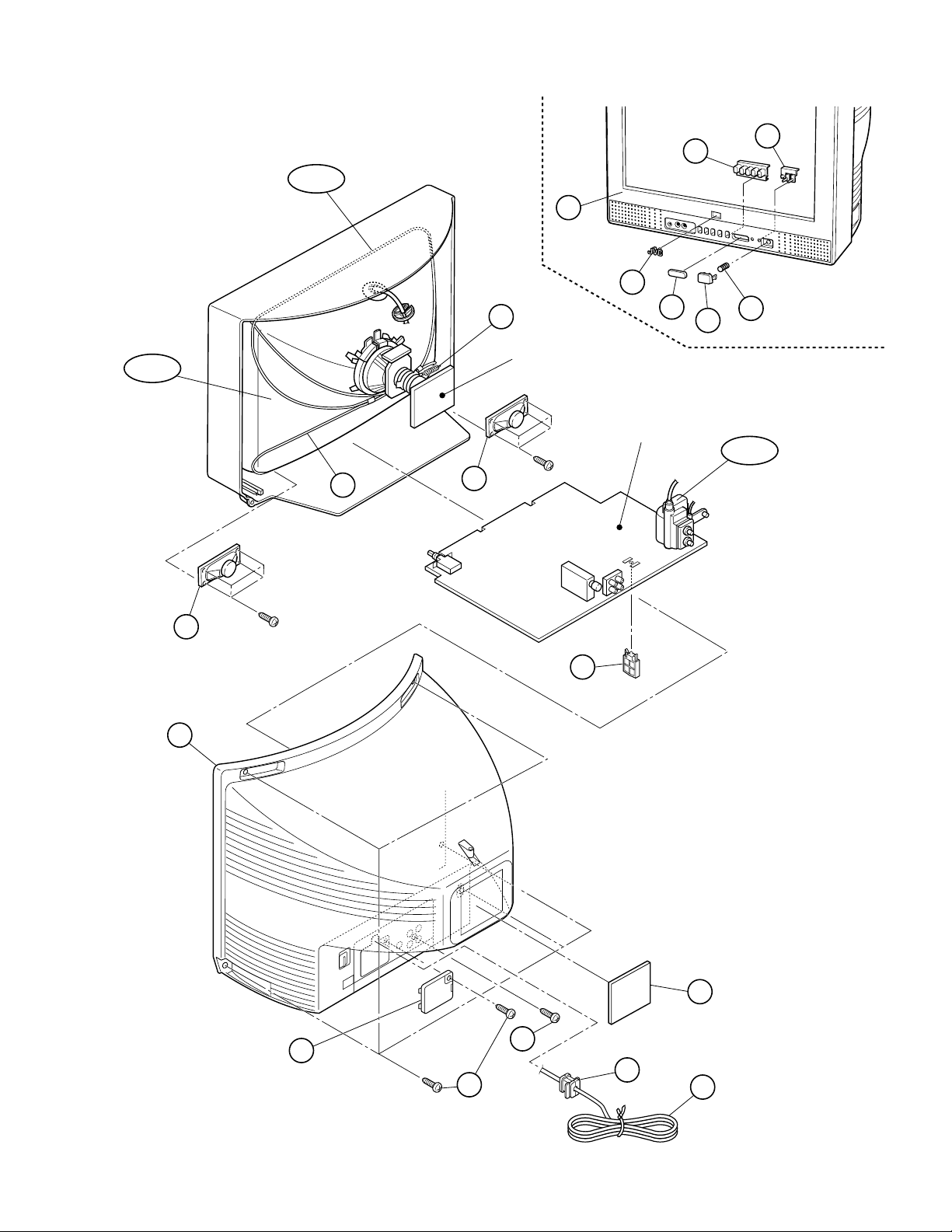
EXPLODED VIEW
MAIN PWB
!
!
!
!
!
!
15
16
T1522
10
10
8
L01
9
12
1
6
7
2
3
4
5
V01
13
17
18
14
11
CRT SOCKET PWB
(Within MAIN PWB)
!
AV-21EM
No. 56100 3
Page 4
AV-21EM
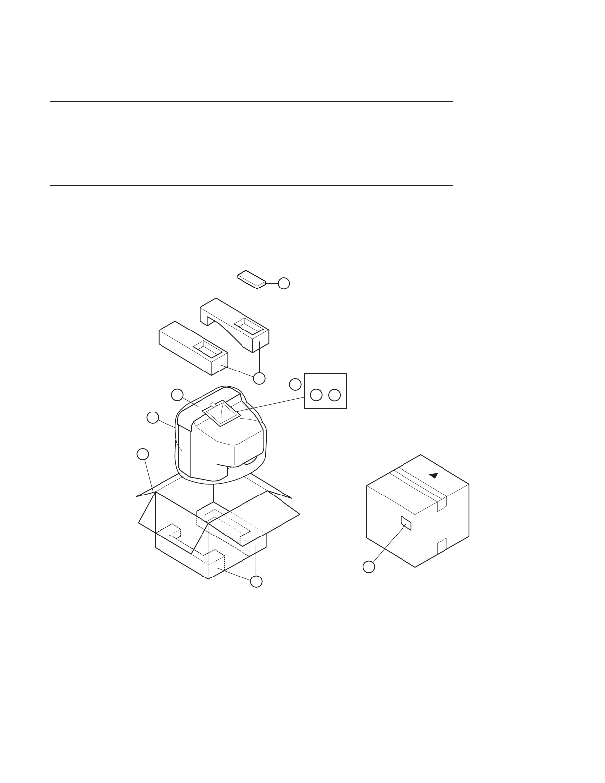
PACKING PARTS LIST
● For AV-21EM/A V -21EM(S)
! Ref.No. Part No. Part Name Description Local
1 LC10660-006A-C PACKING CASE
2 LC40830-001A-C POS/SERIAL LABEL
3 GG10117-001B-C CUSHION ASSY 4 pcs. in 1 set
4 LC31224-001A-C POLY BAG
5 RM-C364-1H REMOCON UNIT
6 LC31262-001A-C POLY BAG
! 7 LCT0907-001A-C INST BOOK
8 CP30992-001-C TOP COVER
PACKING
5
3
8
4
1
3
!
6
7
9
2
REMOTE CONTROL UNIT PARTS LIST (RM-C364-1H)
! Ref.No. Part No. Part Name Description Local
3139 224 20073 BATTERY COVER
No. 561004
Page 5

PARTS DIFFERENCE TABLES
● For AV-21EM
The different parts between AV-21AT and AV-21EM are described below:
AV-21EM
!!
! REF. NO. PART NAME DESCRIPTION
!!
AV-21AT AV-21EM
PART No. PART No.
■ PRINTED WIRING BOARD PARTS LIST [MAIN PWB ASSY] (Page 30-)
— SCG-1247A-H2 SCG-1020A-F2 MAIN PWB ASSY
R1904 QRL03EJ-151X OM R 150Ω 3W J
C1317 NCB31EK-473X CH C CAP. 0.047µF 25V K
NCB21HK-473X CH C CAP. 0.047µF 50V K
C1354 NDC31HJ-271X CH C CAP. 270pF 50V J
NCS21HJ-271X CH C CAP. 270pF 50V J
C1355 NDC31HJ-221X CH C CAP. 220pF 50V J
NCS21HJ-221X CH C CAP. 220pF 50V J
C1356 NDC31HJ-331X CH C CAP. 330pF 50V J
NCS21HJ-331X CH C CAP. 330pF 50V J
C1525 QFZ0200-103 MPP CAP. 0.01µF 1.5kVH ±3%
QFZ0200-972 MPP CAP. 9700pF 1.5kVH ±3%
C1527 QFZ0199-224 MPP CAP. 0.22µF 250V J
QFZ0199-274 MPP CAP. 0.27µF 250V J
C1582 QFZ0199-224 MPP CAP. 0.22µF 250V J
QFZ0199-204 MPP CAP. 0.2µF 250V J
C1651 QTNC1HM-105Z BP E CAP. 1 µF 50V M
QENC1HM-225Z BP E CAP. 2.2 µF 50V M
C1653 QETN1HM-474Z E CAP. 0.47µF 50V M
QFV71HJ-334Z TF CAP. 0.33µF 50V J
C1909 QEZ0199-127 E CAP. 120µF 400V M
QEZ0476-127 E CAP. 120µF 400V M
C1949 NDC31HJ-471X CH C CAP. 470pF 50V J
NCS21HJ-471X CH C CAP. 470pF 50V J
L1551 QQLZ018-430 QQLZ018-460 HEATER CHOKE
No. 56100 5
Page 6

AV-21EM
● For A V -21EM (S)
The different parts between AV-21AT and AV-21EM(S) are described below:
!!
! REF. NO. PART NAME DESCRIPTION
!!
AV-21AT AV-21EM(S)
PART No. PART No.
■ PRINTED WIRING BOARD PARTS LIST [MAIN PWB ASSY] (Page 30-)
— SCG-1247A-H2 SCG-1271A-H2 MAIN PWB ASSY
R1904 QRL03EJ-151X OM R 150Ω 3W J
C1525 QFZ0200-103 MPP CAP. 0.01µF 1.5kVH ±3%
QFZ0200-972 MPP CAP. 9700pF 1.5kVH ±3%
C1527 QFZ0199-224 MPP CAP. 0.22µF 250V J
QFZ0199-274 MPP CAP. 0.27µF 250V J
C1582 QFZ0199-224 MPP CAP. 0.22µF 250V J
QFZ0199-204 MPP CAP. 0.2µF 250V J
C1651 QTNC1HM-105Z BP E CAP. 1 µF 50V M
QENC1HM-225Z BP E CAP. 2.2µF 50V M
C1653 QETN1HM-474Z E CAP. 0.47µF 50V M
QFV71HJ-334Z TF CAP. 0.33µF 50V J
C1909 QEZ0199-127 E CAP. 120µF 400V M
QEZ0476-127 E CAP. 120µF 400V M
L1551 QQLZ018-430 QQLZ018-460 HEATER CHOKE
■ P ACKING PARTS LIST (Page 34)
— CP20527-00K-H PACKING CASE ASSY
No. 561006
Page 7

SPECIFICATIONS (Page 2)
Item Content
Dimensions (W × H × D) 497mm × 454mm × 478.5mm
Mass 21kg
TV RF System B / G, I, D / K, K1
Colour System TV Mode PAL / SECAM
VIDEO Mode PAL / SECAM / NTSC3.58 / NTSC4.43
Receiving Frequency VHF (VL) 46.25MHz ~ 168.25MHz
VHF (VH) 175.25MHz ~ 463.25MHz
UHF 471.25MHz ~ 863.25MHz
CATV ● Cable TVs of Mid (X-Z, S1-S10)
Super (S11-S20) & Hyper (S21-S41) bands receivable
Intermediate VIF Carrier 38.0MHz
Frequency 31.5MHz (6.5MHz)
SIF Carrier 32.0MHz (6.0MHz)
32.5MHz (5.5MHz)
33.5MHz (4.5MHz)
Colour Sub Carrier Frequency PAL (4.43MHz)
SECAM (4.40625MHz / 4.25MHz)
NTSC (3.58MHz / 4.43MHz)
Aerial Input Terminal 75Ω Unbalanced
Power Input AC110 ~ 240V, 50 / 60Hz
Power Consumption 105W (Max.)/68W (Avg.)
Picture Tube Visible size : 51cm measured diagonally
High Voltage 26.5kV ± 1.5kV (at zero beam current)
Speaker 5cm × 9 cm Oval type × 2
Audio Output 5W (Monaural)
Input Video 1Vp-p, 75Ω
Audio 500mVrms (−4dBs), High impedance
Output Video 1Vp-p, 75Ω
Audio 500mVrms (–4dBs), Low impedance
Headphone Jack Stereo mini jack (3.5ø)
Remote Control Unit RM-C364-1H (Battery size : AA/R06/UM-3 × 2)
AV-21EM
Design & specifications are subject to change without notice.
No. 56100 7
Page 8

AV-21EM
SPECIFIC SERVICE INSTRUCTIONS
SETTING OF SYSTEM CONSTANT SET (Page 7)
Table 1
Setting item Setting contents
COLOUR TRIPLE b
BILINGUAL NO b
TUNER MU b
ECO SENSOR YES b
LANGUAGE E/R/U b
B/B SOUND OFF b
LOCK 180 b
COLOUR AUTO NO b
QSS MINT b
ALC NO b
TEXT RATE 20 b
AMP TUNER NO b
VNR YES b
EW-PIN IC NO b
MULTI. TRIPLE PAL
YES NO
MU MA
YES NO
E/R/C/U E/R/C E/R/U E/C
ON OFF
YES 10 20 ... 230
250 240
YES NO
MINT MQSS
YES NO
10 20 40 80
YES NO
YES NO
YES NO
AV-21EM AV-21EM(S)
Setting value
USER SETTING VALUES (Page 7)
Table 2
Setting item Setting value Setting item Setting value
SUB POWER ON PICTURE MODE (VSM) BRIGHT
CHANNEL POSITION 1 POSITION VNR OFF
CHANNEL PRESET
VOLUME Appropriate sound volume AUTO SHUTOFF OFF
TV/VIDEO TV ECO SENSOR OFF
ON SCREEN DISPLAY POSITION NUMBER DISPLAY BLUE BACK OFF
COLOUR SYSTEM AUTO PAL ON TIMER PR1 0:00
SOUND SYSTEM B / G CHILD LOCK OFF
Refer to OPERATING
INSTRUCTION
OFF TIMER OFF
LANGUAGE ENGLISH
No. 561008
Page 9

SERVICE ADJUSTMENTS
■ Initial Setting Value
■ IF CIRCUIT ADJUSTMENT -- Adjustment of DELAY POINT (Page 15)
AV-21EM
Setting (Adjustment) Item
DELAY POINT
(AGC TAKE-OVER)
Variable Initial setting
range value
0 ~ 127 43
■ V/C (VIDEO/CHROMA) CIRCUIT ADJUSTMENT (Page 15)
[SUB MENU 2. V/C]
Colour system Variable Initial setting value
Setting item range PAL SECAM NTSC 3.58 NTSC 4.43
1. CUT OFF (R / G / B) −128 ~ +127 −50 bbb
2. DRIVE (R / B) −64 ~ +63 0 bbb
3. BRIGHT −128 ~ +127 0 bbb
4. CONT. −64 ~ +63 0 bbb
5. COLOUR (P / S / N3 / N4) −64 ~ +63 0 bbb
6. TINT (N3 / N4) TV / VIDEO −64 ~ +63 0 / +80 / 0
7. SECAM BL ADJUST −32 ~ +31 0 bbb
8. SHARP TV / VIDEO −32 ~ +31 −5 / +15 bbb
: Do not adjust.
Adjustment of SUB COLOUR-II (Page 18)
Adjustment part Description
5. COLOUR
PAL COLOUR Value (A) in the figure: Set to +8V (W & G).
SECAM COLOUR Value (A) in the figure: Set to +6V (W & G).
NTSC 3.58 COLOUR Value (A) in the figure: Set to +8V (W & G).
Adjustment of SUB TINT-II (Page 19)
Adjustment part Description
6. TINT
NTSC 3.58 TINT Value (B) in the figure: Set to +7V (W & Cy).
No. 56100 9
Page 10

AV-21EM
■ DEFLECTION CIRCUIT ADJUSTMENT (Page 20)
[SUB MENU 3. DEF]
Setting item Adjustment name Variable range
1. VER. POSITION Vertical center −4 ~ +3 −1 −3
2. HOR. POSITION Horizontal center −16 ~ +15 +3 +3
3. VER. HEIGHT Vertical height −64 ~ +63 −35 +1
4. VER. LINEARITY Vertical linearity −32 ~ +31 +15 −1
5. VER. SCURVE Vertical scurve −32 ~ +31 −32 0
6. HOR. VCO ADJUST Horizontal VCO −64 ~ +63 0 0
: Do not adjust.
Initial setting value
50Hz 60Hz
■ VSM PRESET ADJUSTMENT (Page 22)
[Setting Values for SUB MENU 4. VSM PRESET]
VSM preset
VSM mode BRIGHT STANDARD SOFT
Setting item
TINT
SETTING VALUE
COLOUR
SETTING VALUE
BRIGHT
SETTING VALUE
CONT.
SETTING VALUE
SHARP
SETTING VALUE
+15
+15
+15
+30 +15 +11
+15 +15 +12
bb
b
bb
bb
b
bb
bb
b
bb
bb
b
bb
bb
b
bb
bb
b
bb
: Do not adjust.
No. 5610010
Page 11

AV-21EM
■ PRESET ADJUSTMENT (Page 23)
[SUB MENU 5. PRESET]
Colour system Initial setting value
Setting item PAL SECAM NTSC 3.58 NTSC 4.43
1. C-TRAP FIX 1 bbb
2. SHARP PEAK 0 bbb
3. ABL 1 bbb
4. GAMMA 0 bbb
5. Y.DELAY TIME TV 0 2 2 3
VIDEO 0 2 0 2
6. BLACK EXP START 3 bbb
7. C-BPF TV 1 b 0 b
VIDEO 1 bbb
8. CW/SCP 0 bbb
9. V.IF DET. LEVEL 0 bbb
11. IF AGC MIN. 0 bbb
12. V.IF AGC 0 bbb
13. V.IF PMOD 0 bbb
19. VNR 15 bbb
20. RGB LIM. 1 bbb
21. RGB LIMIT LEVEL 2 bbb
23. TEXT H. POSITION −3 bbb
24. READ DATA
: Do not adjust.
TV RF system Initial setting value
Setting item B/G I D/K M
10. S.IF DET. LEVEL 0 bbb
14. S.IF BPF BW ADJUST 0 bbb
15. S.IF TRAP FO ADJUST 0 bbb
16. S.IF TRAP FO ADJUST 2 0 bbb
17. S.IF-TRAP 0 bbb
18. S.IF-BPF 0 bb 1
22. S.IF SW 1 bb 0
: Do not adjust.
No. 56100 11
Page 12

AV-21EM
VICTOR COMPANY OF JAPAN, LIMITED
TELEVISION RECEIVER DIVISION 1106 Heta, Iwai-city, Ibaraki-prefecture, 306-0698, Japan
No. 5610012
AV21EM-F #3
AV21EMS-SKF #3
CTH 0009
CRT
 Loading...