

Page 1
3
SERVICE MANUAL
COLOUR TELEVISION
AV-21E3
AV-21E
BASIC CHASSIS
CG
CONTENTS
! SPECIFICATIONS ・・・・・・・・・・・・・・・・・・・・・・・・・・・・・・・・
!
SAFETY PRECAUT IONS ・・・・・・・・・・・・・・・・・・・・・・・・・・・・・・・・
! FEATURES・・・・・・・・・・・・・・・・・・・・・・・・・・・・・・・・
! FUNCTIONS ・・・・・・・・・・・・・・・・・・・・・・・・・・・・・・・・
!
SPECIFIC SERVICE INSTRUCTIONS
! SERVICE ADJUSTMENTS ・・・・・・・・・・・・・・・・・・・・・・・・・・・・・・・・
!
PARTS LIST
★
OPERATING INSTRUCTIONS
★
STAND AR D CIRCUIT DIAGRAM
1
・・・・・・・・・・・・・・・・・・・・・・・・・・・・・・・・・・・・・・・・・・・・・・・・・・・・・・・・・・・・・・・・
・・・・・・・・・・・・・・・・・・・・・・・・・・・・・・・・・・・・・・・・・・・・・・・・・・・・・・・・・・・・・・・・
・・・・・・・・・・・・・・・・・・・・・・・・・・・・・・・・・・・・・・・・・・・・・・・・・・・・・・・・・・・・・
・・・・・・・・・・・・・・・・・・・・・・・・・・・・・・・・・・・・・・・・・・・・・・・・・・・・・・・・・・・・・・・・
・・・・・・・・・・・・・・・・・・・・・・・・・・・・・・・・・・・・・・・・・・・・・・・・・・・・・・・
・・・・・・・・・・・・・・・・・・・・・・・・・・・・・・・・・・・・・・・・・・・・・・・・・・・・・・・・・・・・・・・・
・・・・・・・・・・・・・・・・・・・・・・・・・・・・・・・・・・・
・・・・・・・・・・・・・・・・・・・・・・・・・・・・・・・・・・・・・・・・・・・・・・・・・・・・・・・・・・・・・・・・
・・・・・・・・・・・・・・・・・・・・・・・・・・・・・・・・・・・・・・・・・・・・・・・・・・・・・・・・・・・・・・・・
・・・・・・・・・・・・・・・・・・・・・・・・・・・・・・・・・・・・・・・・・・・・・・・・・・・・・・・・・・・・・・・・
・・・・・・・・・・・・・・・・・・・・・・・・・・・・・・・・
・・・・・・・・・・・・・・・・・・・・・・・・・・・・・・・・・・・・・・・・・・・・・
・・・・・・・・・・・・・・・・・・・・・・・・・・・・・・・・・・・・・・・・・・・・・・・・・・・・・・・・・・・・・・・・
・・・・・・・・・・・・・・・・・・・・・・・・・・・・・・・・・・・・・・・・・・・・・・・・・・・・・
・・・・・・・・・・・・・・・・・・・・・・・・・・・・・・・・・・・・・・・・・・・・・・・・・・・・・・・・・・・・・・・・
・・・・・・・・・・・・・・・・・・・・・・・・・・・・・・・・
・・・・・・・・・・・・・・・・・・・・・・・・・・・・・・・・・・・・・・・・・・・・・・・・・・・・・・・・・・・・・・・・
・・・・・・・・・・・・・・・・・・・・・・・・・・・・・・・・・・・・・・・・・・・・・・・・・・・・・・・・・・・・・・・・
・・・・・・・・・・・・・・・・・・・・・・・・・・・・・・・・
・・・・・・・・・・・・・・・・・・・・・・・・・・・・・・・・・・・・・・・・・・・・・・・・
・・・・・・・・・・・・・・・・・・・・・・・・・・・・・・・・・・・・・・・・・・・・・・・・・・・・・・・・・・・・・・・・
COPYRIGHT © 2002 VICTOR COMPANY OF JAPAN, LTD.
・・・・・・・・・・・・・・・・・・・・・・・・・・・・・ 2
・・・・・・・・・・・・・・・・・・・・・・・・・・・・・・・・・・・・・・・・・・・・・・・・・・・・・・・・・・
・・・・・・・・・・・・・・・・・・・・・・・ 3
・・・・・・・・・・・・・・・・・・・・・・・・・・・・・・・・・・・・・・・・・・・・・・
・・・・・・・・・・・・・・・・・・・・・・・・・・・・・・・・・・
・・・・・・・・・・・・・・・・・・・・・・・・・・・・・・・・・・・・・・・・・・・・・・・・・・・・・・・・・・・・・・・・
・・・・・・・・・・・・・
・・・・・・・・・・・・・・・・・・・・・・・・・・
・・・・・・・・・・・・・・・・・・・・・ 13
・・・・・・・・・・・・・・・・・・・・・・・・・・・・・・・・・・・・・・・・・・
・・・・・・・・・・・・・・・・・・・・・・・・・・・・・・・・・・・・
・・・・・・・・・・・・・・・・・・・・・・・・・・・・・・・・・・・・・・・・・・・・・・・・・・・・・・・・・・・・・・・・
・・・・・・・・・・・・・・・・
・・・・・・・・・・・・・・・・・・・・・・・・・・・・・・・・
・・・ 4
・・・・・・
・・ 5
・・・・
31
2-1
6
No. 52028
Jul. 200 2
Page 2
A
V-21E3
SPECIFICATIONS
ITEM
Dimensions(W×H×D) 497mm×454mm×478.5mm
Mass 21kg
TV RF System B/G, I, D/K,
Colour System
Picture Tube Visible size: 51cm measured diagonally
High Voltage 26. 5kV±1.5kV(at zero beam current)
Receiving Frequency VHF (VL) 46.25MHz~168.25MHz
Intermediate
Frequency
Colour Sub Carrier Frequency
RF Mode PAL / SECAM
VIDEO Mode PAL / SECAM / NTSC3.58 / NTSC4.43
VHF (VH) 175.25MHz~463.25MHz
UHF 471.25MHz~863.25MHz
CATV
VIF Carrier 38.0MHz
SIF Carrier
Cable TVs of Mid (X-Z, S1-S10)
Super (S11-S20) & Hy per (S21-S41) bands receiv able
32.5MHz(5.5MHz)
31.5MHz (6.5MHz)
32.0MHz (6.0MHz)
PAL (4.43MHz),
SECAM (4.40625MHz / 4.25MHz)
NTSC (3.58MHz / 4.43MHz)
CONTENT
Power Input Rated Voltage AC110~240V, 50 / 60Hz
Power Consumption 90W (Max) / 60W(Avg)
Speaker 5cm×9cm, Ov al type×1
Audio Output 3W (monaural)
Aerial Input Terminal 75Ω Unbalanced
Input Video 1V(p-p), 75Ω (Front / Rear)
Audio
Output Video 1V(p-p), 75Ω
Audio 500mV(rms) (-4dBs), Low im pedance,
Headphone jack 3.5mm mini jack
Remote Control Unit
500mV(rms) (-4dBs), High impedanc e,
RCA×2 (Front / Rear)
RM-C364GY
(Battery size : AA / R06 / UM-3×2)
Design and specifications are subject to change without notice.
2
No. 52028
Page 3
A
SAFETY PRECAUTIONS
V-21E3
1. The d es i gn of th is pr od uc t c on ta ins sp ecial har d ware, ma ny
circuit s and components specially for saf ety purposes. For
con tinu ed pr ot ecti on , n o chan g es sh ou ld be ma de to the o ri g i nal
d esign un less a uth or i zed i n writin g by th e ma nu fact ur er .
Replacem ent p arts m ust b e i d entic al to thos e used in th e origin al
ci rcu it s. S er vi ce sho uld b e p er formed by qu alif i ed p ers on nel
on ly.
2. Alte r ation s of t he desig n or circui tr y of t he pr od ucts s h oul d not be
made. Any design alterations or additions will void the
manu fac t urer 's warra nt y and will f urth er r el i eve t he ma nufac tu rer
of r esp onsib ili ty for per s o na l inj ur y or p r op erty dam age r esul t in g
th erefr om.
3. Man y electrical an d m ec h ani c a l p ar ts i n th e pr od uc ts ha ve
special safety-related chara cteristics. T hese characteristics are
oft en no t e vi den t f rom vi sua l insp ection n or c a n t he pr o tect io n
aff orde d by th em nece ssar i l y be ob tai n ed b y u sing rep lacem ent
com po ne nts rated f or hig he r vo l tage, w att ag e, etc. Rep l acemen t
p arts whic h ha ve th ese sp ecial s afet y ch ar act er ist ics ar e
ide ntified in the parts list of S ervic e manua l. El ectric al
components having such features are ide ntified by shading
on the sche mat ic s and by (!!!! ) on the parts list in Service
manual. The us e of a sub stitu te r ep lacem en t which do es n ot
h ave th e sam e s af ety ch aract erist ics as t he r eco mm en de d
replac em ent par t sh ow n i n th e p ar ts list of Ser v i ce man ual may
cause shock, fire, or other hazards .
4. Don't shor t between the LIVE s ide ground and ISOLATED
(NE UTRAL) side ground or EARTH side ground when
repairing.
Some model's power circuit is partly different in the GND. The
diff erenc e of th e G ND i s sho wn b y th e LIVE : (") side GN D, the
ISO LATE D(N EUTR AL) : ( #) side G ND and EAR TH : ( $) side
GND. D o n't sh ort b et ween the LIV E sid e GND an d
ISO LATE D(N EUTR AL) si de GND or EAR TH side GN D an d
n ever mea sure w it h a m ea sur i ng a ppa r atus (oscilloscop e etc.)
th e LI VE sid e GN D an d IS OLA TED(NE UTR AL ) sid e G ND or
EARTH sid e GND at the s ame time.
If above not e will not be kept, a fuse or any parts will be broken.
5. If any repair has been made to the chassis, it is recommended
th at t he B1 set ti ng s hou l d b e ch ec ke d or adj u s te d (Se e
ADJUSTM ENT OF B 1 POW E R SUPPLY).
6. The hi gh vol ta ge app li e d t o th e pi c tu re tu be must con form wit h
th at sp ec i fi ed in S er vic e m an ual . E xces siv e h i gh volt ag e ca n
cau se an i nc r e as e i n X- R ay em iss i on , arci ng an d possi b le
component damage, therefore operation under excessive high
voltage conditions should be kept to a minimum, or should be
preve nt ed. If s ever e arc in g oc curs, r em ove t he AC pow er
immed iate l y and de ter m i ne th e cause b y visua l i nspect io n
(incor r ec t in stal lat i on, cr ac ke d or melte d hi gh vo lt age har ness ,
p oor so lder ing, et c.) . T o m ai nt ain the p r ope r min im u m l e v el of
sof t X-R ay em is sion, c ompon en ts i n th e high voltag e c ircui try
incl ud i ng t he pict ur e tu be must b e t he e x act r ep l aceme nts or
alte rn at ives ap pr ov e d b y th e ma nuf act ur er of th e c om pl et e
prod uct.
7. Do not c hec k high volt ag e by dr aw ing an arc. Use a hi gh volt age
meter or a hig h v oltag e prob e wi t h a V T VM . Di s cha rg e th e
picture tube before attempting meter connection, by connecting
a cl i p le ad to th e gr ou nd f rame a nd c onn ectin g th e oth er end of
the lead through a 10kΩ 2W resis to r to the anod e b utt on .
8. When se r vice is r equ ire d, ob serve th e or i gi na l lea d dr ess. E xtr a
prec aut i on sh ou ld b e g iven t o as sure correct lea d dr ess i n th e
high vol tag e cir cui t a rea. W her e a s hor t ci r c uit h as occu rre d,
th ose co mpon ent s tha t i ndi ca te evi de nc e of ove rhea ti ng sho ul d
b e r e pl ac e d. A l wa ys use th e ma nuf act ur er 's r ep l acemen t
components.
9. Isolation Check
(Safety for Electrical Shock Hazard)
Af ter r e- ass emblin g th e p r oduct, al ways per f orm an i s ol at ion
ch eck on the expo sed metal p ar ts of t he c abin et ( a nte nn a
ter m i na ls, vid eo /audio i npu t and ou tput t ermin als, Con tr ol kn obs,
metal cabin et, scr ew he ad s, ea r ph one jack, c on trol shaf ts, etc.)
to be su re th e p r oduct is s af e t o o pe r ate with ou t d an ger of
elect ric al shoc k.
(1) Dielectric Strength Test
The iso lation be tween the A C pr ima ry c i rcu it an d al l me tal p ar ts
exp osed t o the us er, p ar ticular ly an y e xpos ed met al p art h aving a
retu rn p ath to t he chass is sho ul d withs tan d a volt age of 3 000 V
AC (r.m.s.) for a period of one sec ond.
(. . . . W it hstan d a vo lt ag e of 1 10 0V AC ( r .m. s.) t o an ap pl ianc e
rate d up to 12 0V , an d 3 00 0V AC ( r .m. s.) to an ap plian ce rat ed
200V or more, for a period of one second.)
This meth od of test r equi res a test equipment n ot g enerally fou nd
in t he serv ic e trad e.
(2) Leakage Current Check
Plug th e AC l in e c ord d ir ect ly in to the A C ou tlet ( do n ot us e a li n e
isol ati o n tr ansf or m er dur in g thi s ch eck.) . Usi n g a " Lea kag e
Current T este r", me as ur e th e lea kag e cu rre nt f rom each exp osed
metal p ar t of the ca bine t, p art icu larly any e xpos ed me tal p art
h aving a re turn path to the c h as sis , to a kn own go od ea rt h
grou nd (w a ter pip e, e tc.). An y l eaka ge c ur r en t must n ot e xceed
0.5mA AC (r.m.s.).
Howev e r, in tr op ic al area , th is mu st no t exce ed 0.2 mA AC
(r.m.s.).
"""" Alte rn at e Che ck M et hod
Plug th e AC l in e c ord d ir ect ly in to the A C ou tlet ( do n ot us e a li n e
isol ati o n tr an sfor m er dur i ng t hi s che ck .) . Use an AC vo ltmeter
h aving 1 00 0 oh ms pe r vol t or more sens it i vity i n th e fo llow ing
mann er . C on nec t a 1 50 0Ω 10W res ist or par a lle le d b y a 0 .1 5µF
AC-type c apa c it or bet ween an ex po s ed met al pa rt a nd a k no wn
g ood e ar th gr o und ( water pi pe , etc.) . M eas ur e th e A C vo lt ag e
acr oss th e res ist or with th e AC vo l tm eter. Move th e r es istor
con nec tion to e ac h expose d metal par t, p art icul ar l y a ny exp osed
metal p ar t havi n g a r etu rn pat h to the ch assi s, an d m easu r e th e
AC vol tag e ac ross the res ist or . No w , re v er se th e pl u g in th e AC
ou tl et and r e pe at eac h m ea s ur em en t. An y volt ag e me asu re d
must no t e xceed 0 .7 5V AC (r.m. s.) . This c orre sponds to 0.5mA
AC (r.m.s.).
Howeve r, in tropica l are a, this must n ot exce ed 0 .3V AC ( r.m.s.).
This corresponds to 0.2mA AC (r.m.s.).
AC VOLT MET ER
(HAVING 1000 Ω /V,
OR MOR E SENSIT IVITY)
0.15μF AC-T YPE
PLACE THIS PROBE
1500 Ω 10W
GOOD EARTH GROUND
ON E A C H EX PO SE D
ME T AL PA RT
No.52028
3
Page 4
A
V-21E3
FEATURES
"
New c h as sis d es i gn en ables us e of an i nt eracti ve on- scr ee n cont ro l.
"
Wide ran ge volt age (1 10V ~240V) AC power input.
" With AUD IO / VI DEO INPUT & OU TPUT te rmi nal.
"
MUT IN G button can red uce th e audi o level to zer o i nst ant ly.
" Func t ion al r em ote co ntrol t o opera te T V set (f or ch annel s e l ect, volume c ontrol, p ow er ON /OFF, etc . ) f rom a d ist anc e.
"
I2C bu s con tr ol ut i lizes singl e chip ICs for IF, V /C , D EF. V SM PRES ET, PR ESET & S ETUP TOU R.
" By m eans of AUTO PR OGRA M, the T V s tati o ns c an b e s electe d autom atica lly a nd the TV cha nn els c an al so b e rearr an ge d aut omatic al ly.
" Built-in ECO MO DE (ECONOM Y, ECOLOGY)
In acco rdanc e with th e br ig ht ness i n a r oo m, th e br ig ht ness and / of con tr ast of th e p icture can b e a djus t ed au tomat ic ally to m ake th e
op ti mu m pictu re which is eas y on th e e ye.
"
Built – in ON TIMER, RETURN + & CHILD LOCK.
SYSTEM BLOCK DIAGRAM
"
IC702
MEMORY
SCL2/SDA2
IC701
MICRO
COMPUTER
IC301
VIDEO/CHROMA
DECORDER
SCL1/SDA1
TU001
TUNER
4
No. 52028
Page 5
A
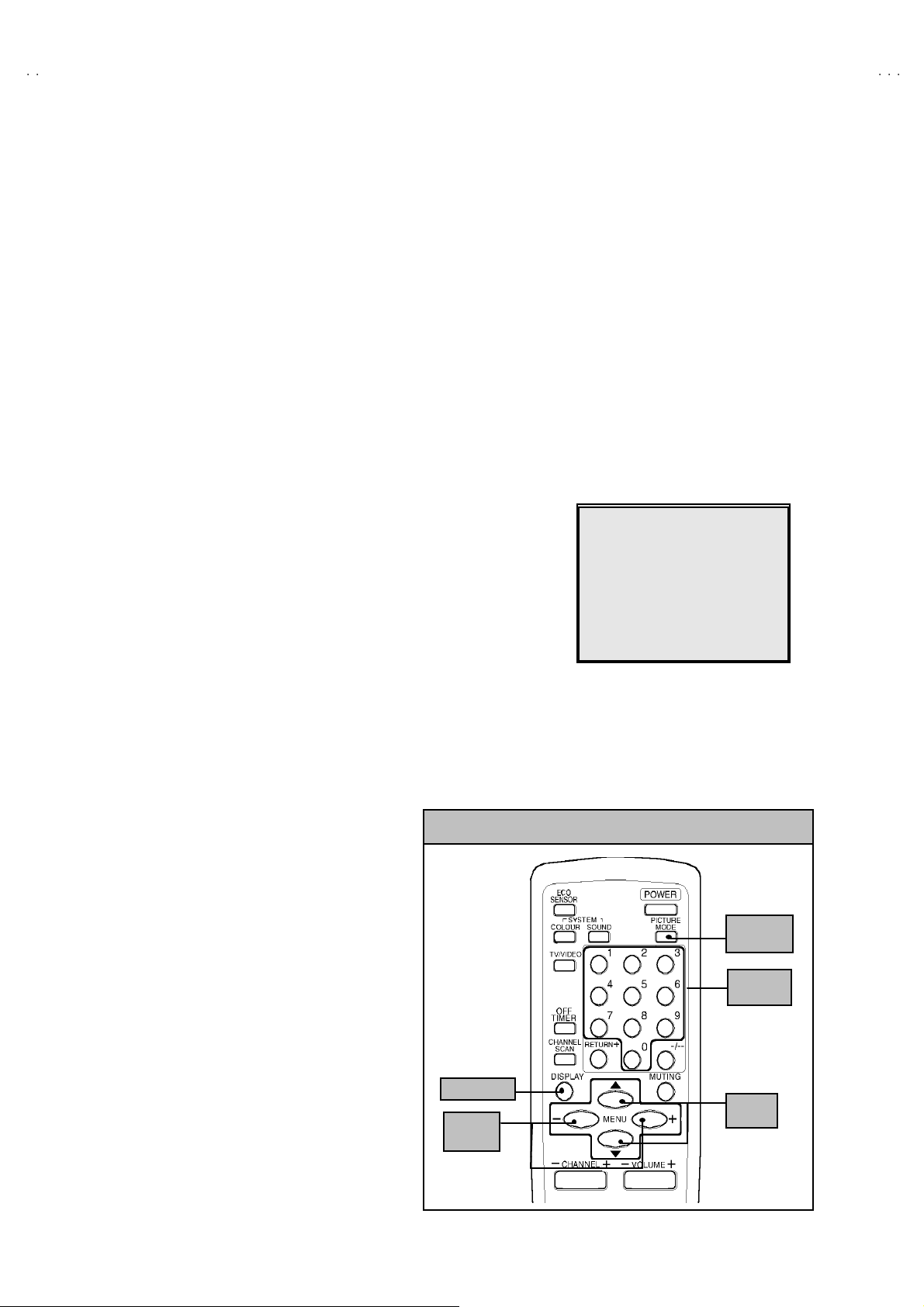
FUNCTIONS
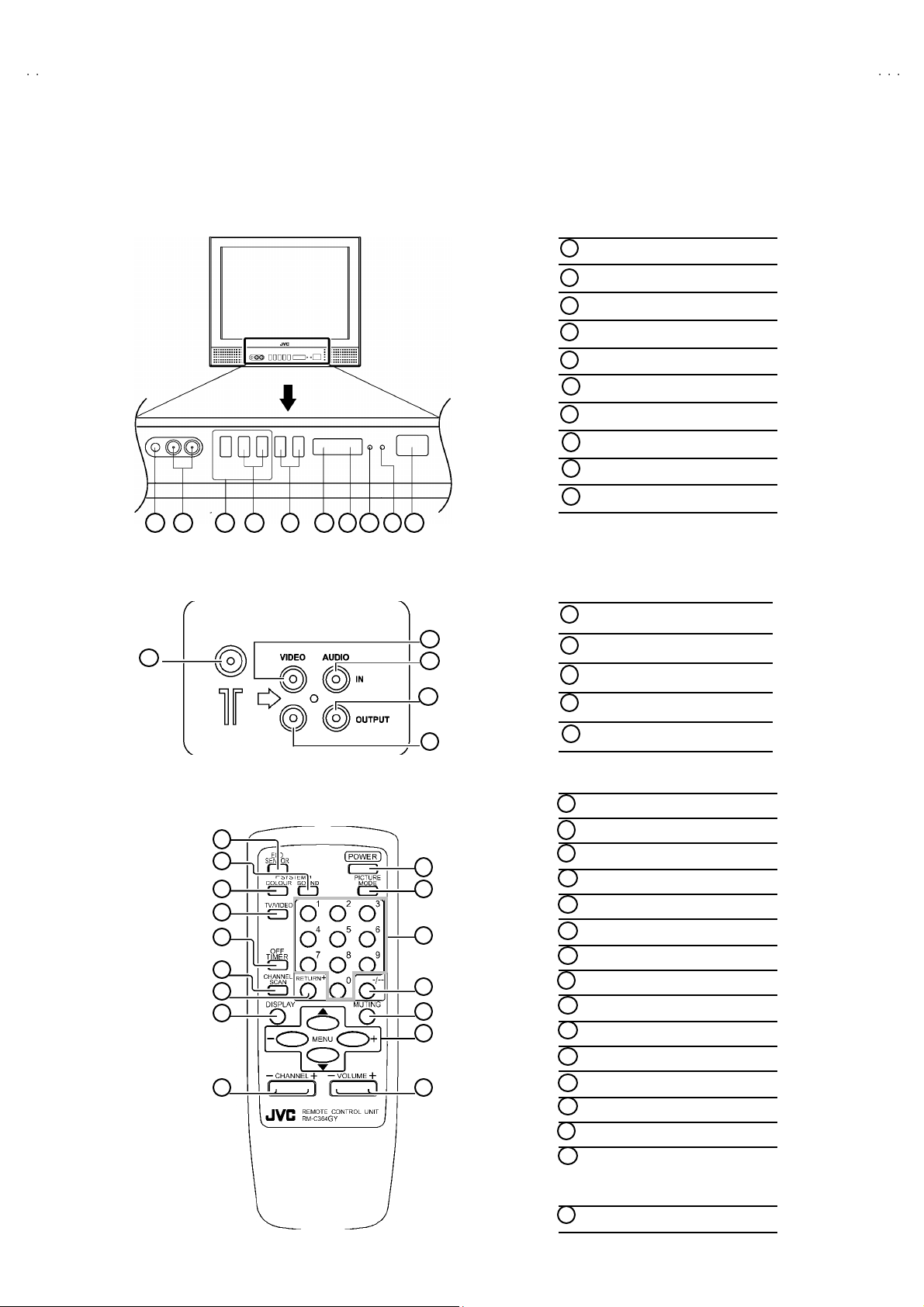
■
FRONT PANEL
10 9 1 2 3 4 5 6 7 8
MENU buttons
1
CHANNEL -/+ buttons
2
VOLUME -/+ bu tto ns
3
AI ECO se nsor
4
REMO TE CON TROL s ens or
5
6
ON TIMER lamp
PO W E R la mp
7
MAIN POWER button
8
9
A/V IN PUT t erminal
10
HEAD PHONE jack
V-21E3
■
REAR TERMINAL
1
■
■
REMOTE CONT RO L UN IT
1
2
3
4
5
6
7
8
9
ANT Terminal
1
2
3
4
5
10
11
12
13
14
15
16
2
VIDEO INPUT Term i nal
3
AUDIO INPUT T ermin al
4
AUDIO OUTPUT Terminal
5
VIDEO OUTPUT Terminal
ECO S ENSOR ke y
1
SOUND SYSTEM key
2
COLO UR SY STEM ke y
3
TV/V IDEO ke y
4
OFF TIMER key
5
CHAN NE L SCAN k ey
6
RETURN+key
7
DISPLAY key
8
CHANNEL key
9
POWER key
10
PICTURE MODE key
11
Number (CH.) key
12
-/--key
13
MUTING ke y
14
MENU ke y
15
MENU ▲/▼ key
MENU -/+ key
VOL UME-/+ key
16
No. 52028
5
Page 6

A
V-21E3
SPECIFIC SERVICE INSTRUCTIONS
DISASSEMBLY PROCEDURE
REMOVING THE REAR COVER
1. U np lug the po we r plu g.
$.
$$
!!!!
an d a
2. As s h own in f i gur e , remove t he 5 screws marked
screw marked "
3. R em ov e th e b ack bo ar d an d re mo ve the p ow er c ord f rom th e
rear c over.
4. Withdr a w t he r ear co ver to wa rd you .
"and a s crew m arked ####.
""
REMOVING THE MAIN PW BOARD
" After removing the rear cover.
1. Slight l y raise t he bo th side s of th e M AIN PW Boa rd b y han d and
remove the PW B stop per of MAIN P W Bo ard .
2. Withdr a w t he M AIN PW Boa rd backw ar d.
(If nec ess ar y , take off the w ire cl am p, c onn ect or s etc. )
REMOVING THE SPEAKER
" After removing the rear cover.
1. As s h ow n i n figu r e, remove the 2 screws marke d $
CHECKIN G THE MAIN PW BOARD
1. To c h ec k the back s ide of the PW B oard.
1) Pu ll out the MA IN PW Boar d. (Ref er to RE MO VING THE M AIN
PW B oard)
2) Erec t th e PW Board vert ic al l y so th at you ca n easily check th e
b ack side of the PW B oard.
[CAUTION]
" W hen e re cting th e PW Boar d, be caref ul s o t hat there w ill b e n o
contacting with other PW Board.
" Before turning on power, make sure t hat the CRT earth wire and
oth er c o nne cto r ar e p rope rl y c onnect ed.
WIRE CLAMPIN G AND CABLE T Y ING
1. Be sure to cla mp the wire.
2. Never r em o ve th e c able tie used f or tyi ng the w i re s to gethe r.
Sh oul d i t be inad verte ntly remove d, be su re to ti e th e wi r es with a
new cable tie.
6
No. 52028
Page 7
A
FRONT CABI.
V-21E3
CRT SOCKET
PWB
SP EAKER
MAIN PWB
HV T
D
(××××2)
REAR
COVER
PWB STOPE R
C
(×××× 1)
B
(××××1)
BACK BOARD
A
(×××× 5)
POWER
CORD
No. 52028
7
Page 8
A
V-21E3
S
U
/C
COLOU
O
REPLACEMENT OF MEMORY ICs
1. MEMORY ICs
Thi s m od el u ses me mo r y I Cs. Thi s me mo r y IC da ta ar e f or pr o per opera tion of th e vide o and deflect ion circui ts .
When r ep la cing me m ory IC s, b e s u r e to us e ICs w r it ten wi th t he ini tial v a lu es of dat a.
2. PROCEDURE FOR REPLACIN G MEMORY ICs
(1) Power off
Switch the p ow er of f and di sco nnect t he pow e r pl u g from t he wall out let.
(2) Replace ICs
Be sure to use memory ICs written with the initial data values.
(3) Power on
Connect th e pow er pl u g int o the wal l ou tl et and s witch t he powe r on .
(4) C heck an d set SY STEM CO NSTANT SET
・・・・ It must not adjust without adjustment signals.
1) Press the DI SPLAY ke y and th e PICTURE MODE key of the REMOTE
CONTROL UNIT simultaneously.
2) The SERVICE MENU screen of Fig. 1 will be displayed.
3) W hil e the SE RV ICE MENU is displ ayed , ag ain press the DISPL AY key and
PICTURE MODE ke y si m ul ta neo usly, an d t he S YSTEM CONSTA NT SE T
screen of Fig. 2 will b e displa ye d.
4) C heck th e s ett in g valu es of th e SYS T EM C ON ST A NT SET of T able 1 If th e
valu e is diff er ent, se lect the s ettin g item with th e MENU ▼/▲key, and set
th e co rr ect valu e w ith t he MENU - / + k ey.
5) Press the DI SPLAY k e y tw i ce, and retu rn to th e n ormal sc r ee n.
(5) Receive channel of setting
Refe r to th e OPE R ATI NG INST RUCTIONS and set the r ece ive c ha nn els
(chan nels prese t) as desc r ibe d
(6) User Setting
Check t he us er s ettin g valu e of T ab l e 2, a nd if se tting value is dif feren t, set
th e co rr ect valu e.
For setting , r ef er to the OPE RATING INSTRUCTIO NS.
(7) Setting of SERVICE MENU
Ve rif y the set ti ng it ems of th e SE RVIC E M ENU, and reset w he re n ecess a r y.
For setting , r ef er to the SERVICE ADJUSTMENTS.
KEY ASSIGNMENT OF REMOTE CONTROL UNIT
1.IF 2.V
3.DEF 4.VSM PRESET
5.PRESET
6.SETUP TOUR OFF
1-6 SELECT DISP : EXIT
******
****** *****
************
SYSTEM CONSTA NT SET 1
: SELECT
- / + : OPERATE DISP : EX IT
SYSTEM CONSTA NT SET 2
: SEL - / + : OPE DISP : E XIT/
ERVICE MEN
***** **
* *.****
* * * *
****
********
** ***
** ***** ***
**********
*** ** **
*** ** ** ** ***
*** ** ***** ** **
Fig.1
SY STEM C ON STANT-
R : TRIPLE
BILINGUAL : NO
TUNE R : MU
ECO SENSOR : YES
LANG UAG E : E / R
/
SY STEM C ON STANT- ⅡⅡⅡⅡ
B/B SO UND : OFF
LOCK : 180
COL OUR AU TO : NO
QSS : MINT
ALC : NO
TEXT R ATE : 2 0
SY STEM C ON STANT- ⅢⅢⅢⅢ
ⅠⅠⅠⅠ
PICTURE
MO DE k e y
NUMBERS
SYSTEM CONSTA NT SET 3
AMP TUNER : N
VNR : YES
TEXT TABLE : CYL
VOLUM PWM : POS
key
: SEL - / + : OPE DI SP : EXIT/
DISPLAY
key
MENU
-/+
key
8
MENU
▼/▲ key
No. 52028
Fig.2
Page 9
A
SE TTING OF SY ST EM CONST ANT SET
Setting item Setting contents Setting value
V-21E3
COLOUR
BILINGUAL
TUNER
AI ECO S ENSOR
LA NG UA G E
B/B SOU ND
LO CK
COLOUR AUTO
QSS
ALC
TEXT RATE
AMP TUNER
VNR
TEXT TABLE
VOL UM PW M
MUL TI . PA LTRIPLE
YE S NO
MA
MU
YE S NO
E/R/A /P
ON OFF
YES 10 20 ~ 230 240 250
YE S NO
MI NT MQ SS
YE S NO
10 20 40 80
YE S NO
YE S NO
ARA CYL
POS
E/R
NEG
Table 1
TRIPLE
NO
MU
YE S
E / R
OFF
18 0
NO
MI NT
NO
20
NO
YE S
CYL
POS
USER SE TTING V ALU ES
Setting item Setting value Setting ite m Setting value
SUB POWER ON LANGUAGE ENGLISH
CHA NNEL PO SITIO N 1 PO SITIO N CHA NNEL PRESET Refe r t o OPE RATIN G I NS T RUCTION
VOL UME About 10 AI ECO S EN SOR OFF
TV/V IDEO
ON SCR EEN DI SPLAY
COLOUR SYSTEM PAL ON TIMER PR1 0:00
SOUND SYSTEM B / G BLUE BACK OFF
OFF TIMER OFF OSD.Shows 00 CHI LD LO CK OFF
PICTURE MODE (VSM) BRIGHT SETUP TOUR ON
TV VNR OFF
POSITION IND ICATIO N AUTO SHUTOFF OFF
Table 2
No. 52028
9
Page 10

A
V-21E3
INITIAL SETTING VALUE OF SERVICE MENU
1. Ad just ment of the SE RVIC E M EN U is made on the bas is of th e in itial s et ting va lu es ; howev er, t he new se ttin g va lu es w hich
set the screen in its optim um condition may differ from the initial setting.
2. Do no t c hange the initial Setting Values of the Setting (Adjustment) items not listed In “ADJUSTMENT”.
2. V/C
Colour system
Setting item
RED
GREE N1. CUT OFF
BL UE
2. DRI VE
3. BR I G HT -127~+127 + 0
4. CONT . -63~+6 3 + 0
RED
BL UE
Variabl e
range
-128 ~+127
-128~+127 + 0
PA L SE CAM NT SC 3.5 8 NT SC 4.4 3
-50
Initial setting value
5. COLOUR
6. TIN T
7. SECAM BL ADJ.
8. SHARP
3. DEFLECTION
1. VER. POS ITION -04 ~ +03 - 1 - 3
2. HOR. POSITION -16 ~ +15 + 3 + 3
3. VER. HEIGHT -64 ~ +63 -35 + 1
4. VE R . L I NE AR I T Y -32 ~ +31 +15 - 1
5. VER. S CURV E -32 ~ +31 -32 + 0
6. H O R. VC O AD J UST
4.VS M PRESE T
mode
VS M
Setting item
TINT SETTING VA LUE +15
COLOUR SE TTIN G VA LUE +15
(Do Not Adj. )
Setting item Variable range
TV
VI DEO
TV - 8(Fixed)
VI DEO
(Do Not Adj. )
VS M pr eset
-63~+6 3
-63~+6 3
-31~+3 1 + 0
-32~+3 1
-63 ~ +62 + 0 + 0
BRIGHT STANDARD SOFT
+ 0
+ 0 + 0
+ 0 + 0
+15(Fixed)
Initial setting value
fv : 50Hz MODE fv : 60Hz MODE
BR IG HT SET TING VA LUE +15
CONT . SE TTING VA LUE +30 +15 + 11
SHARP SE TTIN G VA LU E +15 +1 2
10
No. 52028
Page 11

A
5. PRESE T
The items in the fol lowing table, it is no requirement for adjustment.
If va lues had chang ed by the miss operation, se t the init ial setting value s i n the f ollo wing table.
Colour Syst em Do No t Adju st
V-21E3
Setting item
1. C TRAP FIX 1 1 1 1
2. SHARP PEAK 0 0 0 0
3. A BL 1 1 1 1
4. GAMMA 0 0 0 0
TV 0 2 2 3
5. Y. DELAY TIME
VI DEO 0 2 0 2
6. BL ACK EX P STAR T
TV 1 1 0 0
7. C-BPF
VI DEO 1 1 1 1
8. CW / SC P 0 0 0 0
9. VIF DET LEVEL 0 0 0 0
11. IF AGC MIN 0 0 0 0
12 . VIF AGC 0 0 0 0
13. VIF PMOD 0 0 0 0
19 . VN R 15 15 15 15
PA L SE C AM NT SC 3.5 8 NT SC 4.4 3
+3 +3 +3 +3
Initial setting value (Fix ed v alue)
20 . R GB LIM 1 1 1 1
21. RGB LIMIT LEVEL 2 2 2 2
23. TEXT H. POSITION -3 -3 -3 -3
24. READ DATA
Sound System D o Not Ad ju s t
Setting item B/G I D/K M
10. SIF DET LEVEL +0 +0 +0 +0
14. SIF BPF BW ADJUST
15. SIF TRAP FO ADJUST +0 +0 +0 +0
16. SIF TRAP FO ADJUST 2 +0 +0 +0 +0
17. SIF -TRAP 0 0 0 0
18. SIF -BPF 1 0 0 0
22 . SIF SW 0 1 1 1
+
0
+
0
+
0
+
0
No. 52028
11
Page 12

A
V-21E3
REPLACEMENT OF IC301 (IF V/C DECODER)
" For the I C301(I F V/C DEC ODER ) of this mode l, all data are writ ten in the micro-computer. So, wri te the data in the micro-
computer in accordance with the following procedures before starting adjustment.
PROCEDURES
(1) T ur n t he POW E R O FF.
(2) R epl ace t he IC30 1 with a n ew o ne .
(3) W hile pr essing ME NU bu tto n a nd VO L+ bu tto n ON the F RO NT C ABINE T simul t ane ous l y, t urn th e POW ER ON. Wh en th e POW ER i s
turn ed ON, th e d at a is wr itten i n t he micro-co mputer imm ediately.
LOCATIONS OF FRONT PANEL BUTTONS AND LAMPS
MENU buttons
MENU buttons
1
1 2345678
CHANNEL ・ / ・ butto ns
CHANNEL -/+buttons
2
(ME NU ・ / ・ bu tt ons)
(ME NU -/+b uttons)
VOLUME -/+ buttons
VOLUME -/+ buttons
3
(MENU -/+ bu tto ns)
(MENU -/+ bu tto ns)
AI ECO sensor
AI ECO sensor
4
REMOTE CONTROL sensor
REMOTE CONTROL sensor
5
ON TIMER lamp
ON TIMER lamp
6
POWER lamp
POWER lamp
7
MAIN POW ER button
MAIN POW ER button
8
12
No. 52028
Page 13

A
SERVICE ADJUSTMENTS
BEFORE STARTING SERVICE ADJUSTMENT
1. Ther e ar e 2 w ay o f adjus ti ng t hi s T V: One i s wi th t he
REMOTE CONTROL UNI T and the other is the conventional
method using adjustment parts and components.
2. The adjustment with the REMOTE CONTROL UNIT is made
on the basis of t he initial settin g v alue s. The setting va lues
which adjust the screen to its optimum condition may differ
from the init ia l s etting v al ues.
3. M ake s ure th at conn ect ion is c orr ect l y made t o AC p ower
source.
4. Turn on the p ower of th e se t an d eq uipm en t bef ore use, an d
start t he ad ju stm en t proc edures af ter waitin g at least 30 mi n ute s.
5. U nl ess ot her w ise s pec if i ed, p r ep ar e th e mo st suita bl e r ec epti o n
or inp ut sign al for adjust ment.
6. Nev er t ouch a ny ad ju s tme nt part s, whi ch ar e no t spe cif ied
in t he li st for thi s adju st me nt VR s , t ra nsforms, conde n ser s,
etc.
7. Pr ep ar atio n for ad j ustm en t
Unless otherwise specified in the adjustment instructions, preset
the following functions with the REMOTE CONTROL UNIT.
User mode position
PICTURE MODE (VSM) BRIGHT
VNR OFF
TINT / COLOUR / BRIG HT
CONT. / SHARP
BLUE BA CK OFF
OFF TIMER OFF
AI ECO S ENSOR OFF
AUTO S HUT OFF OFF
V-21E3
CENTER
MEASURING INSTRUMENT AND FIXTURES
1. DC voltmeter (or digital voltmeter)
2. Oscilloscope
3. Si gn al g en er ator (P attern g en erat or) [ PAL / S ECAM / N T S C]
4. Remote control unit
ADJUSTMENT ITEMS
Adjustment item Ad justment item
B1 POW E R SUPPL Y
FOCUS adjustment VSM PRESET setting
IF ci rc uit a djust ment
V/C (Video / Chroma) circuit adjustment
DEFLECTION c ircuit adjustment
PURITY/ CO NV ER GENCE adjus tm ent
No. 52028
13
Page 14
A
V-21E3
3
BASIC OPERATION OF SERVICE MENU
"
The adjustment using SERVICE MENU
The f ol l ow i ng adj us tme nt it ems u s e t he SE RV ICE MENU in th e s er ies of the adju stment . The ad ju stm ent s ar e m ade on the bas is of the
initial se tting valu es. Th e adju stm ent valu es whic h adju st t he scr een to the o pti m um c o ndi t ion c an be di ffere nt from th e in iti a l sett in g values.
With th e SERVIC E ME NU, vari ous s ett in gs c an be made , a nd the y are br oa dl y cl as sifie d i n the f ollo win g ite ms of s etti n gs .
1.I F ・・・・・・・ ・・・・・・・・・・・・・ ・・・ Adjustment of the IF circuits.
2.V /C ・・・・・・・・・・・・・・・・・・・・・・ Ad ju stm en t of th e VIDEO /CH RO MA cir cuit.
3.DEF ・・・・・・・ ・・・・・・・・・・・・・ ・ Ad justment of th e DEFL ECT ION circ uit.
4.V SM PRES ET ・・・・・・・ ・・・・・ Ad ju stm en t of th e i ni t ia l sett in g value s of VSM co ndit i on as STA NDA RD, SOFT a nd BR IGHT.
(VSM : Video Status Memory)
5.PRESET
6. SETUP TOUR OFF ・・・・・・・ It s hou l d be abl e to sel ect m ode (LAN GU AG E and AU T O CH PRESE T )..
"
Key operation of the SERVICE MENU
[Enter to SERVICE MENU]
Press the DI SPLAY key and the PICTURE MODE key of the REMOTE CONTROL
UNIT s i mu lt an eously. Th en ent er th e S ERVIC E MEN U mod e as sh ow n in F i g.1 .
[Exit from SERVICE MENU]
When complete th e ad j us t ment wor k, press th e DISPLA Y key to retur n t o th e
SERVICE MENU.
An d th en pr ess th e DISPLA Y ke y ag ain, retur n to th e n orm al sc r een .
[ Se lec t fr o m SE RVIC E M ENU]
In SERVI CE M ENU , press t he n umber ( 1 ~6) k e y of the remo te c ont ro l un it , to se l ect
an y of th e adj us tm en t items.
The colour s whi c h selecte d i te m ch ar act ers are ch anged .
・・・・・・・ ・・・・・・・・・・
Adjustment of the RF circ uit [Do not adjust].
[Should be OFF].
SE RVICE MEN U
1.IF 2.V/C
.DEF 4.VSM PRESET
5.PRESET
6.SETUP TOUR OFF
1-6 SELECT DISP : EXIT
******
***********
***** **
************
**********
*** ** **
*** ** **** ***
*** ** ***** ** **
**.***
****
** ***
** ***** ***
***
******
Fig.1
14
DI SPL A Y ke y
-/+key
No. 52028
KEY ASSIGNMENT OF REMOTE CONTROL UNIT
MENU
PICTURE
MO DE k e y
NUMBERS
key
MENU
key
▼/▲
Page 15

A
[Method of setting]
1. IF
[1. VCO]
① 1 K ey ・・・・・・・ ・・・・・・・・・・・・・ ・・・・・ Select 1.IF.
② 1 K ey ・・・・・・・ ・・・・・・・・・・・・・ ・・・・・ Select 1.VCO
③ The VCO (CW) screen will be displayed a allow mark when the AFC voltage is at a certain level.
④ DISPLA Y K ey・・・・・・・・・・・・・・・・・・ As you press this key twice, you will return to the SERVICE M E NU.
[2. DELA Y P OINT]
① 1 K ey・・・・・・・ ・・・・・・・・・・・・・ ・・・・・ Select 1.IF.
② 2 K ey・・・・・・・ ・・・・・・・・・・・・・ ・・・・・ Se lect 2 .D ELAY P OINT.
③ ME NU -/+ K ey ・・・・・・・ ・・・・・・・・・・ Se t (adjust) th e se tting valu es of th e s etting ite ms.
④ DISPLAY K ey・・・・・・・・・・・・・・・・・・ W hen this is pr esse d twi ce, you w i ll ret ur n to t he SE RVICE MENU .
2.V /C, 3.D EF an d 4.V SM PRES ET
① 2~4Key ・・・・・・・ ・・・・・・・・・・・・・ ・・・ Select one from 2. V/C , 3. DEF an d 4. VSM PRE SET.
② MENU ▼/▲ Key ・・・・・・・ ・・・・・・・ Se lect s etting i tems.
③ MENU -/+ Key ・・・・・・・ ・・・・・・・・・・ Adj u s t th e va lues of t he items.
④ DISPLA Y K ey ・・・・・・・ ・・・・・・・・・・・ W hen th is is presse d, re turn t o t he SE RVICE MENU .
V-21E3
6.SE TUP T OUR
① By p r essi ng the 6 key, you can ch ange t he ON or OF F ( should be OFF).
(Should be OFF)
%・
The JVC’s logo will be shown about 15 s econds automatically.
② MENU -/+ Key ・・・・・・・ ・・・・・・・・・・ Select Language.
③ MENU ▼ Key・・・・・・・ ・・・・・・・・・・ Au to Se arch.
If it is ON , th en y ou tu rn th e TV po we r off , wh en y ou ar e tur n the TV p ow er o n aga in .
No. 52028
15
Page 16

A
V-21E3
S
U
6.SETU
JUS
6.SETU
ON /
50
(R)
50
O
SERVICE MENU FLOW CHAR T
SE RVICE MEN U
ERVICE MEN
1.IF 2.V/C
3.DEF 4.VSM PRESET
5.PRESET
P TOUR OFF
1-6 SELECT DISP : EXIT
******
***********
***** **
* *.****
************
**********
*** ** **
*** ** **** ***
*** ** ***** ** **
P TOUR
* * * *
****
********
** ***
** ***** ***
FF
(By pr essi ng 6- ke y)
OFF
SU B ME NU 1. I F
IF
1. VCO
2. DELAY PO INT
1-2 : SELECT DISP : E XIT
SU B ME NU 2. V /C
V/C PAL
1. CUTOFF
(G)
(B)
50Hz
/ :SELECT
- / + : OPERATE DISP : EXIT
* **
* **
* **
VCO (CW)
TOO HIGH
ABOV E REFERENCE
JUST REF ERE NCE
BELOW REF ERENCE
TOO LOW
AFT AD
VCO ADJUST
FINE
AGC TAKE- OVER
- / + : OPER ATE DI SP : EXIT
***.**
T
DELAY POINT UHF
MH z
** *(* *)
** *(* *)
** *(* *)** *(* *)
** *(* *)
** *(* *)
** *(* *)** *(* *)
DISP : EXIT
**
SU B ME NU 3. D EF
DEF
1. VER. POSITION
/ :SELECT
- / + : OPERATE DISP : EXIT
PAL
**
Hz
SUB ME NU 4. V SM PRES ET
BRI GHT
TINT
COLO UR
BRI GHT
CONT.
SHARP
/ :SELECT
- / + : OPERATE DISP : EXI T
**
**
**
**
**
SUB ME NU 5. P RE SET
16
PRESET
1. C-TRAP FI X
/ :SELECT
- / + : OPERATE DISP : EXIT
PAL
Hz
B/K
*
No. 52028
Page 17

A
ADJUSTMENT LOCATIONS
V-21E3
TOP
MAIN PWB
F901
CRT SOCKET PWB
TP-47R/G
TP-47G /R
T
IC701
(SOLDER SIDE)
U
TP-47B
TP-E
E1
CRT EARTH WIRE
(BRAIDED ASS'Y)
4
S
IC702
MEMORY IC
FRONT
DEG
PW
S
IC301
TU00 1
T
1Pin TP-91(B1)
2Pin NC
1
S
HV
U
HVT
UPPER:FOCUS
LOWER:SCREEN
3Pin X-ray2
4Pin X-ray1
5Pin TP-E( )
No. 52028
17
Page 18

A
V-21E3
)
adjust
ADJUSTMENTS
B1 POW ER SUPPLY
Item
Check of
B1 Powe r
Measuring
instrume nt
Signal
generator
Supply
DC Volt meter
FOCU S ADJUSTMENT
Item
Ad j ust men t
of FOCUS
Measuring
instrume nt
Signal
generator
IF CIRCUIT ADJUSTMENT
Item
Measuring
instrume nt
Test point Ad justment part Description
TP-91 ( B1)
####
TP-E (
)
1. Inp ut a wh ole black signa l.
2. Connect a DC voltmeter to TP-91(B1) and TP-E (#).
3. M ake sure t hat th e volt ag e is D C 1 16.5±2.0 V.
Test point Ad justment part Description
FOCUS VR
[In HVT]
1. Input a cross-hatch signal.
2. W hil e watch ing the scre en, adjust the FOCUS VR to make the
ver tic al and hori zonta l l in es as f in e a nd sha rp as possib le.
3. M ake sure t hat w he n the s creen is d ar ken ed, the li nes remain i n
g ood focu s.
Test point Ad justment part Description
Ad j ust men t
of VCO(CW
Signal
generator
Remote
control unit
VCO (CW)
TOO HIGH
AB OVE REFEREN CE
JU ST REF ER ENCE
BEL OW R EFERE N CE
TOO LOW
AFT AD JUST
VCO ADJUST
FINE
DISP : EXIT
ADJUSTMENT AT THIS POINT IS USELESS
***.**
MHz
** *(* *)
** *(* *)
** *(* *)** *(* *)
** *(* *)
** *(* *)
** *(* *)** *(* *)
ADJUSTMENT POINT
1. VC O
YE LLOW
Do not
TOO HIGH
ABOVE REFERENCE
J US T R E FE RE NC E
B ELO W RE F E RE NC E
TOO LOW
●Please use signal generator which is correct proof about the
sen ding fr eque ncy.
1. Inp ut th e PA L f ull col o ur b ar (2 10.2 5MHz) s ig nal .
2. En ter th e SERVICE ME NU.
3. Se lect 1.IF f rom the SERV ICE MENU.
4. Press 1 key and s elect 1.VCO.
5. Select VCO ADJUST with MENU ▲/▼ key.
6. Press MENU -/+ key until the colour of t he characters TOO
HIGH ch an ges b lu e to ye l low. T h en g r ad ual l y pr ess th e MENU
-/+ key u ntil th e TOO LOW c h anges yellow . At this t ime, conf irm
th at t he valu e of VCO ADJUST is near + 00 .
0. Select AFT ADJUST with MENU ▲/▼ key.
8. Press ME NU -/ + key until the characters JUST REFERENCE
ch anges bl ue to yel l ow .
9. Press the DI SPLA Y key three times to return to normal screen.
18
No. 52028
Page 19
A
V-21E3
(QAU0287-001)
(QAU0185-004)
(QAU0282-001)
Item
Ad j ust men t
of DELAY
POI NT
(AGC)
Measuring
instrume nt
Test point Ad justment part Description
Signal
generator
Remote
control unit
DELAY POINT UHF
AGC TA KE-OVER
- / + : OPERATE DISP : EXIT
**
DELAY P OINT
(AGC TAKE-OVER)
1. Inp ut a bl ac k an d wh it e sign al (col o ur of f).
2. En ter th e SERVICE ME NU.
3. Select 1. IF f rom t he SERVI C E M ENU.
4. Select 2 . DELAY P OIN T b y pr es sin g th e 2 key on the remo te
control unit.
5. Se t th e set ting val u es of th e set ting items as s hown bell o w t able .
6. Then adjust the MENU - / + key until video noise disappears.
7. Tur n to oth er ch an nels and m ake su r e th at the re ar e n o
irregularities.
Setting Ite m Variabl e range Initial setting v alue
DELAY P OINT
(AGC TAKE OVER)
NT SC 3.5 8
OTHER
0~127
MATSUSHITA
MURATA
45 45 47
35 45 35
ALPS
No. 52028
19
Page 20

A
V-21E3
(G)
(B)
VIDEO / CHROMA CIRCUIT ADJUSTMENT
The setting (adjustment) using the REMOTE CONTROL UNIT is made on the basis of the initial setting values.
The setting values which adjust the screen to the optim um condition can be different fr om the initial setting valu es.
Do not c hange th e init ial se tting v alue s of the sett ing items not listed in “ADJUSTMENT”.
Item
Ad j ust men t
of WHITE
BALANCE
(Low light)
Measuring
instrume nt
Test point Ad justment part Description
Signal
generator
Remote
control unit
V/C PAL
1. CUTOFF
50Hz
/ :SELECT
- / + : OPERATE DISP : EXIT
(R)
(B)
* **
* **
* **
KEY ASSIGNMENT OF REMOTE CONTROL UNIT
CU TO FF O F F
(H.LINE OFF)
CU TO FF O N
(H.LINE ON)
R. CUTOFF( )
R. CUTOFF( )
▲
▲
R. DRI VE( )
▼
R. DRI VE( )
▼
123
4
7
56
8
9
RGB
1. CUT OFF (R)
CUT OFF (G)
CUT OFF (B)
SCREEN VR
[IN HVT]
G .C UTOFF ( )
B. C UTOF F( )
B. D RIV E( )
B. C UTOF F( )
B. D RIV E( )
G .C UTOFF ( )
▲
▲
▲
▲
▲
▲
1. Inp ut a bl ac k an d wh it e sign al (col o ur of f).
2. En ter th e SERVICE ME NU.
3. S elect 2. V/C fr om th e S ERVICE MENU, then selec t 1 . C UT OFF
(R), (G) and (B) .
4. Set each value to initial setting value with 4~ 9 keys of the
remote control unit.
5. Press the 1 key of th e re mo te co ntr ol un i t to sh ow th e s in gl e
horizontal line on screen.
6. Tur n t he SCREEN VR f ully counter-clockwise, then slowly turn it
cl ockw is e to wh er e on e of a r ed , blu e or gr e en co l our is f aint l y
vis ible.
7. Use keys 4~9 of th e r em ote c ontr o l uni t an d ad ju s t the oth er 2
col o ur s wh i ch exc ep t th e ap pea r ed col o ur to w he r e th e sin gle
h orizo nt al l in e app ea rs whit e.
8. Turn the SCREEN VR to where t he s in gl e h or iz ont al l in e g lows
fain tly.
9. Press the 2 ke y to turn of f th e single hori zon tal line .
10. Press the DISPLAY key t wice to r eturn to th e n ormal screen.
Adjustment item
R
G
Variabl e
range
-128 ~+127
-128 ~+127
Initial setting
value
-50
-501. CUT OFF
B - 128~+127 -50
Ad j ust men t
of WHITE
BALANCE
(Hi gh light)
Signal
generator
Remote
control unit
2. DRI VE (R
DRI VE ( B)
)
1. Inp ut a bl ac k an d wh it e sign al (col o ur of f).
2. En ter th e SERVICE ME NU.
3. S elect 2. V/C fr om th e S ERVICE MENU.
4. Select 2. DRIVE (R) / (B) with MENU ▼/▲ key, and set each
val u e to initial s etti ng val u e with 4 and 7 or 6 and 9 key s of the
remote control unit.
5. Use the keys 4 and 7 or 6 and 9 t o p ro duce a w hite scr een
6. Press the DISPLAY key twice to retu rn to the nomal scree n.
V/C PAL
2. DRIVE
50Hz
/ :SELECT
- / + : OPERATE DISP : EXIT
20
(R)
* **
* **
No. 52028
Adjustment item
2. DRIVE
Variabl e
range
Initial setting
value
R -128~+127 +0
-128 ~+127
B
+0
Page 21

A
V-21E3
Item
Ad j ust men t
of
SUB BRIGHT
Ad j ust men t
of
SUB CONT.
Ad j ust men t
of
SUB
COLOUR ⅠⅠⅠⅠ
Measuring
instrume nt
Remote
control unit
Remote
control unit
Remote
control unit
Test point Ad justment part Description
3. BR I G HT 1. Rec ei ve an y br o adc ast.
2. En ter th e SERVICE ME NU.
3. Select 2. V/C f rom S ERVICE MENU.
4. Select 3. BRIGHT with the MENU ▼/ ▲key.
5. Set the initial setting value with the MENU - / + key.
6. If the brightness is not t he best with the initial set valu e, make
fine adjustment until you get the best brightness.
4. CONT . 1. R eceiv e an y bro adc ast.
2. En ter th e SERVICE ME NU.
3. Select 2. V/C f rom S ERVICE MENU.
0. Select 4. CONT. with the MENU ▼/▲key.
5. Set the initial setting value with the MENU - / + key.
6. If the contrast is no t t he best with th e i nitial s et value, m ak e f ine
adjustment until you get the best contrast.
5. COLOUR [Method of adjustm ent without measuring instrument]
PAL COLOUR
1. R eceive a PAL broa dcast.
2. En ter th e SERVICE ME NU.
3. Select 2. V/C f rom t he SERVI C E M EN U.
4. Select 5. COLOUR with the MENU ▼ /▲ key.
5. Se t th e initia l setting value for PAL COLO UR wit h the MENU
- / + key.
6. If t he co lour is no t th e be st with th e i n itia l s et v al u e, mak e fin e
adjustment until you get the best colour.
SECAM COLOUR
NTSC 3.58 COLOUR
NTSC 4.43 COLOUR
1. R eceive a SEC AM br oadc ast.
2. M ake fi ne adju stm en t of SE CA M CO LOUR as pr eviou sly.
1. R eceive a NTS C 3.5 8MH z broa dca st.
2. M ake si m ila r fi n e ad justm ent of N T SC 3.58 CO LOU R as
previ ously.
When NTSC 3.58 adjustment completed , NTSC 4.43 will be
automatically set at t he respective va lues.
No. 52028
21
Page 22

A
V-21E3
))
g
Item
Ad j ust men t
of SUB
COLOUR
ⅡⅡⅡⅡ
W
Measuring
instrume nt
Signal
generator
Oscillosc ope
Remote
control unit
Y
Cy
Test point Ad justment part Description
TP-47G/R
TP-E (####)
[CRT S OCKET
PWB]
M
5. COLOUR [Method of adjustm ent using measur ing instrument]
R
(A)
PAL COLOUR
B
(-)
0V
(+)
1. Inp ut a PA L full field colou r bar sig nal (7 5% wh it e) .
2. En ter th e SERVICE ME NU.
3. Select 2. V/C f rom S ERVICE MENU.
4. Select 5. COLOUR with the MENU ▼/ ▲ key.
5. Set the initial setting value of PAL COLOUR with the MENU
- / + key.
6. C on nec t the osc illosc ope be tween TP -4 7G /R and TP- E (#).
7. Ad jus t PAL C OL OU R to br i ng th e val u e of (A) in the illu stration
to + 12V (W- G) . (Vol t age v al u e b etween (W) an d ( G))
G
SECAM CO LOUR
1. Input a SECAM full field colour bar signal (75% white).
2. Set the initial setting value of SECAM COLOUR with t he MENU
- / + key.
3. Ad jus t SE C AM CO LOUR to b ri n g th e valu e of
illu str ation t o +8V(W -G). (V oltag e value b etween (W) an d ( G))
(A)
in the
NTSC 3.58 COLOUR
NTSC 4.43 COLOUR
22
1. Inp ut a N TSC 3. 58 ful l fi e ld colo ur b ar s ign al ( 75 % whi te) .
2. Set the initial setting value of NTSC 3.58 COLOUR with the
MENU - / + key.
3. Ad jus t N T SC 3.5 8 COL OUR to bring t he val u e of (A) in t h e
illu s tr ation to +11V(W-G). (Voltage value between (W) a nd (G
When N TSC 3.5 8 is s et, NTSC 4. 43 will be automati ca lly se t at t he
resp ecti v e values .
No. 52028
Page 23

A
V-21E3
y
g
(B)
Item
Ad j ust men t
of TINTⅠⅠⅠⅠ
Ad j ust men t
of TINTⅡⅡⅡⅡ
Measuring
instrume nt
Signal
generator
Remote
control unit
Signal
generator
Oscillosc ope
Remote
control unit
Test point Ad justment part Description
6. TINT [Method of adjustment without measuring instrument]
TP-47G/R
TP-E (####)
[CRT
SOCKET
PWB]
NTSC 3.58 T INT
NTSC 4.43 TINT
6. TINT [Method of adjustment using measuring instrument]
NTSC 3.58 T INT
1. Inp ut a N TSC 3. 58 ful l fi e ld colo ur b ar s igna l ( 75% white) .
2. En ter th e SERVICE ME NU.
3. Select 2. V/C f rom S ERVICE MENU.
4. Select 6. TINT with t he ME NU ▼/▲ key.
5. Set the initial setting value of NTSC 3.58 with the MENU - / +
key.
6. If you c a nn ot get the best tin t wi th th e in i ti al s etti n g v a l ue, ma ke
fine adjustment until you get the best tint.
When N TSC 3.5 8 is s et, NTSC 4. 43 will be automati ca lly se t at t he
resp ecti v e values .
1. Inp ut a N TS C 3.5 8 f ul l fi eld colo ur b ar si gna l (75% white) .
2. En ter th e SERVICE ME NU.
3. Select 2. V/C f rom S ERVICE MENU.
4. Select 6. TINT with t he ME NU ▼/▲ key.
5. Set the initial setting value of NTSC 3.58 with the MENU - / +
key.
6. C on nec t the osc illosc ope be tween TP -4 7G /R a nd TP- E. (#).
7. Adjust NTSC 3.58 TINT to bring the value of (B) in the
illustration to +9V(W- Cy) . (Volta ge val u e b etw ee n ( W ) and
(Cy))
W
B
R
M
(-)
0V
Y
C
G
(+)
NTSC 4.43 TINT
When N TSC 3.5 8 is s et, NTSC 4. 43 will be automati ca lly se t at t he
resp ecti v e values .
No. 52028
23
Page 24

A
V-21E3
Item
of SECAM
BL AC K
OFF SET
KEY ASSIGNMENT OF REMOTE CONTROL UNIT
COLOUR
ON
COLOUR
OFF
Measuring
instrume nt
Remote
control unit
Signal
generator
12 3
Test point Ad justment part Description
7.SECAM
BL ADJUST
[Method of adjustment using measur ing instrument]Ad j ust men t
1. Inp ut a SE CAM ful l f ield c olour b ar sign al .
2. En ter th e SERVICE ME NU.
3. Select 2. V/C f rom S ERVICE MENU.
4. Select 7. SECAM BL ADJUST with MENU ▼/▲ key.
5. Set the initial setting value with the MENU - / + key.
6. Switch the ①ke y (c olou r OF F) an d ②key (c ol ou r ON ) on the
remote co ntr ol an d make sure th at th er e is no colo ur on th e
blac k an d w h it e scr ee n.
7. If t he bl a c k an d whit e s cree n is no t b es t with th e i ni t ial s ett in g
value, make fine adjustment until you get t he b est black and
white sc r een .
8. W hi l e w atc h i ng th e sc r e en, adj us t th e val u e t o be th e s am e
col o ur b etw ee n O N & OFF b y t en key on t he r em ote c ontro l
un it.
9. Press the DISPLAY key twice to retu rn to the normal scr een.
4
7
56
8
9
24
No. 52028
Page 25

A
DEFLECTION CIRCUIT ADJUSTMENT
"
The re ar e 2 mod es of adju s tm ent (s etti ng va l ue) - ----- ① 50 Hz m ode an d ② 6 0Hz m ode - -- - - de pendi n g u pon th e k ind of s igna ls
(ver tic al fr eq uenc y 5 0Hz / 60H z).
"
When ad juste d in m od e ① , mode ② will be automatically s et.
The setting (adjustmen t) usin g the REMOTE CONTROL UNIT is made on the basis of the initial setting values.
The setting values which adjust the screen to the optimum condition can be different from the initial settin g values.
V-21E3
Item
Ad j ust men t
of V.HEIG HT
&
V. POSIT I ON
Screen
size
92%
Measuring
instrume nt
Test point Ad justment part Description
Signal
generator
Remote
control unit
DEF
1. VER. POSITION
/ :SELECT
- / + : OPERATE DISP : EXIT
PAL
50Hz
Scre en s ize
1. VE R. POS ITION
3. VE R. HE I G HT
**
Picture
size
10 0%
1. Inp ut a circle p attern si gn al .
2. En ter th e SERVICE ME NU.
3. Select 3. DEF. f rom S ERVIC E MENU.
4. Select 1. VER. POS ITION with t he MENU ▼/▲ key.
5. Set the initial setting value with the MENU - / + key.
6. Adjust V and V’ to be equal with th e MENU - / + key a s sh own in
Fig.2.
7. Inp ut a cr os s -hatch sign al.
8. Select 3. V. HEIG HT with the MENU ▼/▲ key.
9. Set the initial setting value with the MENU - / + key.
10. As shown in Fig.1, adjust VE R. HE IGH T and mak e the verti cal
screen size 92% of the pictu r e s ize w i th t he MEN U - / + k e ys of
remote control unit.
Ad j ust men t
of HO R.
POSITION
Pic ture size 1 00%
Fig.1
Signal
2.HOR. POSITION 11. Input a circle pattern si gnal.
generator
Remote
control unit
HH"
V
V'
Fig.2
No. 52028
12. Sele ct 2. HOR POSITION with the MENU ▼/▲ key.
13 . Se t the initia l sett i ng value of 2. HOR. POSITION wit h the
MENU - / + key.
14. Adju st 2. HOR. POSITION to make H= H " as sh own in Fig. 2
with the MENU - / + key.
25
Page 26

A
V-21E3
Item
Ad j ust men t
of VER. LI N.
& VER .
SCURVE
Measuring
instrume nt
Signal
generator
Remote
control unit
Fig .3
Test point Ad justment part Description
4. VER. L IN.
5. VER. S CURV E
TOP
CEN TER
BOTTOM
●●●● Whe n the v ertic al lin ea rit y has bee n det e rio rat ed
remark ably, perform the following steps .
15 . Input a cross -hatch signal.
16. Sele ct 4. VER. LIN. with the MENU ▼/▲ key.
17. Set the initial setting value of 4. VER LIN. with the MENU - / +
key.
18. Sele ct 5. VER. SCURVE with the MENU ▼/▲ key.
19. Set the initial setting value of 5. VER . SCURV E wit h th e ME NU
- / + key.
20. Adju st 4. VER. LIN. and 5. VER. SCURVE so that th e s p ac e s
of each lin e as sh ow n i n F i g. 3 o n TOP, CENTER and
BOTTOM become uniform.
Make su r e th at the a dj ust me nt is pr o perly do ne on t he s cre en of
60 Hz mode .
[NOTE]
"
Adjust to make both 50Hz & 60Hz are the same v. size and
fine straight line.
"
When ad just aga i n, adju s t 5 0Hz m ode fi r st.
"
When adjust in 60Hz mode, only 60Hz mode is adjust.
VSM PRESET SETTING
Item
Setting of
VS M
PRES ET
Measuring
instrume nt
Remote
control unit
BRI GHT
TINT
COLO UR
BRI GHT
CONT.
SHARP
/ :SELECT
- / + : OPERATE DISP : EXIT
Test point Ad justment part Description
TINT
COLOUR
BR IG HT
CONT .
SHARP
1. En ter th e SERVICE ME NU.
2. Select 4. VS M PRESE T from the SERVICE MENU.
3. Se lect BRIG HT with th e P ICTURE MODE key.
4. Ad jus t t he M ENU ▼/▲ an d MENU - / + k e y to br ing the s et
val u es of TI NT
tabl e.
5. Resp ectively sel ect th e VSM PRES ET mode f or SOFT an d
STANDARD, and make similar adjustment as in 3 above.
~~~~
SHARP to the values shown in the below
•••• VS M P RESET
VS M
**
**
**
**
**
Setti ng It em
TINT +15
COLOUR +15
BRIGHT +15
CONT +30 +15 +11
SHAR P + 15
BRIGHT STA NDARD SOFT
←
←←
←←
←
←
+12
26
No. 52028
Page 27

A
PURITY / CONVERGENCE ADJUSTMENT
PURITY ADJUST MENT
1. Demag ne tiz e C RT wit h the dem a gn etizer .
V-21E3
2. L oose n th e re tain er scr ew of th e d eflec ti on yoke .
3. Remove th e wed ge s.
4. Inp ut a g reen r ast er sign al fr om the sign al ge ner at or, an d turn
th e scr een t o gr een r aste r.
5. Move the deflection yoke backward.
6. Br ing t he lo ng lug of th e p ur i ty m agn ets on the s ho rt lug a nd
p osition t he m horizon tall y. ( Fig. 2)
7. Ad ju st t he ga p be tween two l ug s so th at the G RE EN R AS TER
will come into the center of the screen. (Fig.3)
8. M ove the deflec t ion yoke forw ar d, a nd fi x th e pos itio n of th e
deflection yoke so that the whole screen will bec ome green.
9. Ins ert th e w e dge t o the t op side of the defl ec t io n yo ke so that it
will not move.
CR T
#
WEDGE
DEFLECTION
YOKE
P
46
P / C
MAGNET S
P/ C MA GN ETS
P : PURITY M AGN E T
4 : 4 P OLES ( c on v er gen c e m agn ets)
6 : 6 P OLES (con ver gen ce m agn ets)
Fig.1
PURITY MAG NETS
10 . Inp ut a cross hat ch sig na l.
11 . Ve rif y that the scr e en is hor izon tal .
12 . Inp ut r ed and b l ue r as t er sign al s, a nd m ak e sur e tha t purity is
prop er l y ad juste d.
Long lug
Short lug
(FRO NT VIEW )
Bring the long lug over the short lug
and position them horizontally.
Fig.2
GREEN RASTER
CEN TER
Fig.3
No. 52028
27
Page 28

A
V-21E3
STAT IC CONVERGENCE ADJUSTMENT
1. Inp ut a cr oss hatc h sig nal.
2. U sing 4 - po le c on v er ge nc e m agn ets , ove rla p t he re d a nd blu e
lines i n th e cen ter of th e sc r een (Fig. 1) and tu rn the m to
mag ent a (r ed/ blue ).
3. Us in g 6 - pol e c on v er ge nc e ma gn ets, over l ap the
mag ent a(red/b l ue) a nd g r een l i nes in t he cen ter of the screen
an d t urn t hem t o whit e.
4. Repeat 2 and 3 ab ove, an d make b est c onver ge nce.
DYNAMIC C ONVERGENCE ADJUSTMENT
1. M ov e th e d ef lec ti on yok e up an d d ow n and over lap th e li n es in
the periphery. (Fig . 2 )
2. Move the def l ecti on yoke left to righ t a nd overlap the lines i n the
p erip her y. (Fi g. 3)
3. Repeat 1 and 2 ab ove, an d make b est c onver ge nce.
(FRO NT VIEW )
(FRO NT VIEW )
BLUE
GREEN
RED
Fig.1
GREEN
BLUERED
RED
GREEN
BLUE
●
After ad justmen t, f i x the wedge at the origin al p osi tion .
Fas t en the r eta in er s crew of th e def lec ti on yoke .
Fi x the 6 magn ets with g lue.
(FRO NT VIEW )
GREEN
RED
BLUE
GREEN REDBLUE
Fig.2
Fig.3
BLUE
GREEN
RED
RED
GREEN
BLUE
BLUE
GREEN
RED
28
No.52028
Page 29

A
REPLACEMENT OF CHIP COMPONENT
!
CAUT IONS
1. Avoid heating for more than 3 seconds.
2. Do n ot ru b the elect ro des an d the resist p ar ts of the patt ern.
3. W hen r em ov ing a c hip part, mel t th e s older ad equate ly.
4. Do n ot reuse a ch ip p ar t afte r re mo v ing it .
! SOLDERING IRON
1. Use a hig h i ns ulati o n s older ing i r on with a t hin poin ted end of it .
2. A 3 0 w s older i ng i r on is rec omm end ed for easily r em oving p ar ts.
! REPLACEMENT STEPS
1. How to remove Chip parts
$$$$ Resi st o rs, capacit ors , etc
(1) As sh own in the f igure, pu s h th e part with tw ee zer s and
alte rn at ely mel t the sol de r at eac h end.
(2) Sh if t with tweeze rs and r em o ve th e ch i p p ar t.
$$$$ Tran s istor s, diodes , varia bl e res ist or s, et c
(1) Ap pl y e xt ra so lder to each le ad .
SOLDE R SOLD ER
V-21E3
2. How to install Chip parts
$$$$
Resi st o rs, ca pacit ors , etc
(1) Ap ply sold er to the pattern as indic ate d in the figure.
(2) Gr as p the ch ip p art with tw ee zer s and pl ac e i t on th e sold er.
The n hea t and me lt th e solder a t b oth en ds of t he chi p part.
$$$$ Tran s istors, diodes , varia bl e r esistor s, etc
(1) Ap ply sold er to the pattern as indic ate d in the figure.
(2) Grasp the ch ip p art wit h t we ezers an d pl ac e it on th e so l der .
(3) First s older lead A as indicated in t he figure.
A
(2) As sh own in the f igure, pu s h th e part with tw ee zer s and
alte rn at ely mel t th e sol d er a t each le ad . S hift an d r em ove the
chip part.
Note : A fte r re moving t he part, r emove remain ing so lder fro m the
pattern.
C
(4) T he n s o ld er l e ads B and C.
A
C
No.52028
B
B
29
Page 30

A
V-21E3
30
No.52028
 Loading...