

Page 1

3
3
SERVICE MANUAL
COLOUR TELEVISION
AV-21DMT3 / AV-21D3
AV-2135TEE / AV-2135EE
/D
AV-21DMT3/AV-21D
AV-2135TEE/AV-2135EE
AV-21DMG
BASIC CHASSIS
CG
AV-21DMG3
[ RM-C3 64GY ][ RM -C9 0 ]
CONTENTS
AV-21DMG3
/
/-A
!
SPECIFICATIONS
!
SAFETY PRECAUT IONS ・・・・・・・・・・・・・・・・・・・・・・・・・・・・・・・・
! FEATU RES・・・・・・・・・・・・・・・・・・・・・・・・・・・・・・・・
! FUNCTIONS ・・・・・・・・・・・・・・・・・・・・・・・・・・・・・・・・
!
MAIN DIFFERENCE LIST ・・・・・・・・・・・・・・・・・・・・・・・・・・・・・・・・
! SPECIFIC SERVICE INSTRUCTIONS ・・・・・・・・・・・・・・・・・・・・・・・・・・・・・・・・
!
SERVICE ADJUSTMENTS
!
PARTS LIST ・・・・・・・・・・・・・・・・・・・・・・・・・・・・・・・・
★ OPERAT ING INSTRUCTIONS
★ STAND ARD CIRCUIT DIAGRAM ・・・・・・・・・・・・・・・・・・・・・・・・・・・・・・・・
1
・・・・・・・・・・・・・・・・・・・・・・・・・・・・・・・・・・・・・・・・・・・・・・・・・・・・・・・・・・・・・・・・
・・・・・・・・・・・・・・・・・・・・・・・・・・・・・・・・・・・・・・・・・・・・・・・・・・・・・・・・・・・・・・・・
・・・・・・・・・・・・・・・・・・・・・・・・・・・・・・・・
・・・・・・・・・・・・・・・・・・・・・・・・・・・・・・・・・・・・・・・・・・・・・・・・・・・・・・・・・・・・・
・・・・・・・・・・・・・・・・・・・・・・・・・・・・・・・・・・・・・・・・・・・・・・・・・・・・・・・・・・・・・・・・
・・・・・・・・・・・・・・・・・・・・・・・・・・・・・・・・・・・・・・・・・・・・・・・・・・・・・・・
・・・・・・・・・・・・・・・・・・・・・・・・・・・・・・・・・・・・・・・・・・・・・・・・・・・・・・・・・・・・・・・・
・・・・・・・・・・・・・・・・・・・・・・・・・・・・・・・・・・・
・・・・・・・・・・・・・・・・・・・・・・・・・・・・・・・・・・・・・・・・・・・・・・・・・・・・・・・・・・・・・・・・
・・・・・・・・・・・・・・・・・・・・・・・・・・・・・・・・・・・・・・・・・・・・・・・・・・・・・・・・・・・・・・・・
・・・・・・・・・・・・・・・・・・・・・・・・・・・・・・・・・・・・・・・・・・・・・・・・・・・・・・・・・・・・・・・・
・・・・・・・・・・・・・・・・・・・・・・・・・・・・・・・・・・・・・・・・・・・・・・・・・・・・・・・
・・・・・・・・・・・・・・・・・・・・・・・・・・・・・・・・・・・・・・・・・・・・・・・・・・・・・・・・・・・・・・・・
・・・・・・・・・・・・・・・・・・・・・・・・・・・・・・・・・・・・・・・・・・・・・
・・・・・・・・・・・・・・・・・・・・・・・・・・・・・・・・・・・・・・・・・・・・・・・・・・・・・・・・・・・・・・・・
・・・・・・・・・・・・・・・・・・・・・・・・・・・・・・・・
・・・・・・・・・・・・・・・・・・・・・・・・・・・・・・・・・・・・・・・・・・・・・・・・・・・・・
・・・・・・・・・・・・・・・・・・・・・・・・・・・・・・・・・・・・・・・・・・・・・・・・・・・・・・・・・・・・・・・・
・・・・・・・・・・・・・・・・・・・・・・・・・・・・・・・・・・・・・・・・・・・・・・・・・・・・・・・・・・・・・・・・
・・・・・・・・・・・・・・・・・・・・・・・・・・・・・・・・・・・・・・・・・・・・・・・・・・・・・・・・・・・・・・・・
・・・・・・・・・・・・・・・・・・・・・・・・・・・・・・・・・・・・・・・・・・・・・・・・
・・・・・・・・・・・・・・・・・・・・・・・・・・・・・・・・・・・・・・・・・・・・・・・・・・・・・・・・・・・・・・・・
COPYRIGHT © 2002 VICTOR COMPANY OF JAPAN, LTD.
・・・・・・・・・・・・・・・・・・・・・・・・・・・・・
・・・・・・・・・・・・・・・・・・・・・・・・・・・・・・・・・・・・・・・・・・・・・・・・・・・・・・・・・・
・・・・・・・・・・・・・・・・・・・・・・・ 3
・・・・・・・・・・・・・・・・・・・・・・・・・・・・・・・・・・・・・・・・・・・・・・
・・・・・・・・・・・・・・・・・・・・・・・・・・・・・・・・・・
・・・・・・・・・・・・・・・・・・・・・・・・・・・・・・・・・・・・・・・・・・・・・・・・・・・・・・・・・・・・・・・・
・・・・・・・・・・・・・・・・・・・・・・・ 7
・・・・・・・・・・・・・・・・・・・・・・・・・・・・・・・・・・・・・・・・・・・・・・
・・・・・・・・・・・・・・・・・・・・・
・・・・・・・・・・・・・・・・・・・・・・・・・・・・・・・・・・・・・・・・・・
・・・・・・・・・・・・・・・・・・・・・・・・・・・・・・・・・・・・ 33
・・・・・・・・・・・・・・・・・・・・・・・・・・・・・・・・・・・・・・・・・・・・・・・・・・・・・・・・・・・・・・・・
・・・ 4
・・・・・・
・・ 5
・・・・
・・・・・・・・・・・・・ 8
・・・・・・・・・・・・・・・・・・・・・・・・・・
15
・・・・・・・・・・・・・・・・2-1
・・・・・・・・・・・・・・・・・・・・・・・・・・・・・・・・
2
No. 52023
Jun. 2002
Page 2

A
V-21DMT3/AV-21D3
A
A
S
U
/C
NUMBERS
GU
O
/
3
V-2135TEE/AV-2135EE
V-21DMG3
REPLACEMENT OF MEMORY ICs
1. MEMORY ICs
Thi s mod el u ses me mo r y I Cs. This memo r y IC da ta are f or pr o per opera tion of th e vide o a nd defl ect io n cir cuits.
When r ep la cing memory ICs , b e su r e to use ICs w r it ten w i th t he ini tial v a lu es of dat a.
2. PROCEDURE FOR REPLACIN G MEMORY ICs
(1) Power off
Switch the p ower of f and di sc o nn ect t he pow e r plu g f rom t he w al l out let.
(2) Replace ICs
Be sure to use memory ICs written with the initial data values.
(3) Power on
Connect th e pow er plu g i nt o the wal l ou tl et and s w itch t he po we r on .
(4) C heck and s et SY STEM CONSTAN T SET
・・・・ It must not adjust without adjustment signals.
1) Press th e DI SPLAY key and the PICTURE MODE key of the REMOTE
CONTROL UNIT simultaneously.
2) The SERVICE MENU screen of Fig. 1 will be displayed.
3) W hi l e th e SE RV IC E M EN U is di splayed , ag ain press the DI SPLAY ke y and
PICTURE MODE ke y s imulta neo us l y, an d t he S YSTEM C ONSTA NT SE T
screen of Fig. 2 w ill b e di splayed.
1) Check the s ettin g val ue s of the S YST E M CO N ST AN T S ET of T abl e 1 If th e
val u e is diffe re nt, select the sett ing item with the MENU ▼/▲key, and set
th e co rrect valu e with t he MENU - / + k ey.
5) Press the DISPL AY ke y tw ice, and r etu rn t o the n or m al sc r ee n.
(5) Receive channel of setting
Refe r to th e OPE RATING INST RUCTIONS and set th e rec e i ve cha nn els
(chan nels prese t) as descr i be d
(6) User Setting
Check t he us er s etti n g v al u e of T ab l e 2, and if setti ng v alue is di f feren t, set
th e co rrect valu e.
For setting , refer to the OPE RATING INSTRUCTIO NS.
(7) Setting of SERVICE MENU
Ve rif y the s et ting it ems of th e SER VICE MENU, and r eset whe r e n ecess a r y.
For setting , refer to the SERVICE ADJUSTMENTS.
NOTE
Alth ou gh th e k ey p osi tion of t he RM-C90 r e mote control unit is diff erent fr o m
th at of th e RM -C36 4GY rem ot e cont rol un it , th e f unctio ns of both u ni ts a re the
sam e So pl e as e use th e attac hed d i agr am for the RM-C90 remote control
uni t fo r the R M-C36 4GY.
By t he way, MENU -/+ Key fu nction s in t he sam e ma nner as for / key.
KEY ASSIGNMENT OF REMOTE CONTROL UNIT
ERVICE MEN
1.IF 2.V
3.DEF 4.VSM PRESET
5.PRES ET
6. TURB O T I MER O F F
1-6 SELECT DISP : EXIT
******
***********
***** **
************
**********
*** ** **
*** ** **** ***
*** ** ***** ** **
**.***
****
** ***
** ***** ***
***
******
Fig.1
SY STEM C ON STA NT- ⅠⅠⅠⅠ
SYSTEM CONSTA NT SE T 1
COL O UR :
BI LIN
AL : N
TUNE R : MU
ECO SENSOR : YES
LANG U AG E :
: SELECT
- / + : OPERATE DISP : EXIT
***
***
SY STEM C ON STA NT- ⅡⅡⅡⅡ
SYSTEM CONSTA NT SE T 2
B/B SO UND : OFF
LOCK : 180
COL OUR AU TO :
QSS : MINT
ALC : NO
TEXT R ATE : 2 0
: SELECT
/
- / + : OPERATE DISP : EXIT
***
SY STEM C ON STA NT-
SYSTEM CONSTANT SET
AMP TUNER : NO
VNR : YES
TEXT TABLE :
VOLUM PWM : POS
***
ⅢⅢⅢⅢ
10
DI SPL A Y k ey
MENU
/ key
PICTURE
MO DE k e y
MENU
▼/▲
key
(RM-C90)
key
No. 52023
: SELECT
/
- / + : OPERATE DISP : EXIT
Fig.2
Page 3

A
3
A
A
SE TT ING OF SY STEM C ON STANT SET
A
Setting item Setting contents
OLOUR
BILINGUAL
TUNER
AI ECO S ENSOR
MUL TI . PA LTRIPLE
YE S NO
MU MA
YE S NO
E/R/A /P E/C E/R
LA NG UA G E
E/C/ M/I
E/R/U
V-21DMT3/AV-21D
V-2135TEE/AV-2135EE
AV-
21DMT3
AV-
21D3/D
MULTI. TRIPLE TRIPLE MULTI.
NO
MU
YE S
E/R/A /P
E/C/ M/I E/R/U E/R/A /P
Setting value
AV-
2135TEE
AV-
2135EE
AV-
21DMG3
V-21DMG3
AV-
21DMG3
/- A
B/B SOU ND
YES 10 20 ~ 230
LO CK
250 240
COLOUR AUTO
QSS
ALC
TEXT RAT E
10 20 40 80
AMP TUNER
VNR
TEXT TABLE
VOL UM PW M
USER SE T TING V ALUES
Setting item Setting value Setting item Setting value
ON OFF
YE S NO
MI NT
MQ SS
YE S NO
YE S NO
YE S NO
RA CYL
POS
NEG
OFF
18 0
NO
MI NT
NO
20
NO
YE S
ARA
POS
Table 1
ON
YE S
CYL
SUB POWER ON LANGUAGE ENGLISH
CHA NNEL PO SITIO N 1 PO SITIO N CHA NNEL P RE SET Refe r t o OPE RATIN G I NS TRUCTION
VOL UME About 10 AI ECO S EN SOR OFF
TV/V IDEO
ON SCR EEN DI SPLAY
TV VNR OFF
POSITION INDICATION AUTO SHUTOFF OFF
COLOUR SYSTEM PAL ON TIMER PR1 0:00
SOUND SYSTEM B / G BLUE BACK OFF
OFF TIMER OFF OSD.Shows 00 CHI LD LO CK OFF
PICTURE MODE (VSM) BRIGHT
Table 2
No. 52023
11
Page 4

A
V-21DMT3/AV-21D3
A
A
)
V-2135TEE/AV-2135EE
V-21DMG3
INITIAL SETTING VALUE OF SERVICE MENU
1. Ad just m ent of th e SER VICE MENU is m ade o n th e bas is o f the initial s et ti ng va lues ; ho wev er , t h e new se tting values w hi ch
set the screen in its optimum condition may differ from the initial setting.
2. Do not change the initial Setting Values of the Setting (Adjustment) items not listed In “ADJUSTMENT”.
2. V/C
Initial set ting v al ue
Setting item
2. DRI VE
3. BR IG HT
Colour sy stem
RED
GREE N1. CUT OFF
BL UE
RED
BL UE
Variabl e
range
-128 ~+127
-128 ~+127
-127~+127
PA L SE CAM NT SC 3.5 8 NT SC 4.4 3
-50
+ 0
+ 0
4. CONT .
5. COLOUR -63~+63 + 0
TV
AV -2 1D3/ D
AV -2 135T EE
6. TINT
7. SE C AM BL AD J . -31~+31
8. SHARP
3. DEFL ECTION
1. VER. POS ITION -04 ~ +03 - 2 - 3
2. HOR. POSITION
3. VER. HEIGHT
4. VE R . L I NE AR ITY
5. VER. SWCURVE
6. H OR. VC O AD J US T
VI DEO
Do Not Ad j.
Setting item Variable range
AV -2 135EE
AV -2 1DMT3
AV -2 1DMG 3
AV -2 1DMG 3/- A
TV - 8(Fixed)
VI DEO
Do Not Ad j.
-63 ~+63
-63 ~+63
-32~+31
-16 ~ +15
-64 ~ +63
-32 ~ +31
-32 ~ +31
-63 ~ +62
+ 0
+ 0 + 0
+0 + 0
+8 + 0
+ 0
+15(Fixed
Initial set ting v al ue
fv : 50Hz MODE fv : 60Hz MODE
+1 + 4
-40 + 0
+13 - 3
-32 + 0
+ 0 + 0
4. VS M PRESE T
12
VS M pr eset
VSM mode
Setting item
TINT SETTING VA LUE +1 5
COLOUR SE TTIN G VA LU E +15
BR IG HT SET TING VA LUE +1 5
CONT . SE TTING VA LU E +30 +15 + 11
SHARP SE TT IN G VA LU E +1 5 +1 2
BRIGHT STANDARD SOFT
No. 52023
Page 5

A
3
A
A
5. PRESE T
The items in the following table, it i s no requirement for adjustment.
If va lues had changed by t he miss operation, se t the initial settin g v alue s i n the following table.
Colour Sy stem Do No t Adju st
V-21DMT3/AV-21D
V-2135TEE/AV-2135EE
V-21DMG3
Setting item
1. C TRAP FIX 1 1 1 1
2. SHARP PEAK 0 0 0 0
3. A BL 1 1 1 1
4. GAMMA 0 0 0 0
TV 0 2 2 3
5. Y. DE LAY TIME
VI DEO 0 2 0 2
6. BL ACK EX P ST ART
TV 1 1 0 0
7. C-BPF
VI DEO 1 1 1 1
8. CW / SCP 0 0 0 0
9. VIF DET LEVEL 0 0 0 0
11. IF AGC MIN 0 0 0 0
12 . VIF AGC 0 0 0 0
13. VIF PM OD 0 0 0 0
19 . VN R 15 15 15 15
PA L SE CAM NT SC 3.5 8 NT SC 4.4 3
+3 +3 +3 +3
Initial set ting v al ue ( Fixed value)
20 . R GB LIM 1 1 1 1
21. RGB LIMIT LEVEL 2 2 2 2
23. TEXT H. POSITION -3 -3 -3 -3
24. READ DATA
Sound System D o Not Ad j u s t
Setting item B/G I D/K M
10. SIF DET LEVEL +0 +0 +0 +0
14. SIF BPF BW ADJUST
15. SIF TRAP FO ADJUST +0 +0 +0 +0
16. SIF TRAP FO ADJUST 2 +0 +0 +0 +0
17. SIF -TRAP 0 0 0 0
18. SIF -BPF 1 0 0 0
22 . SIF SW 0 1 1 1
+
0
+
0
+
0
+
0
No. 52023
13
Page 6

A
V-21DMT3/AV-21D3
A
A
V-2135TEE/AV-2135EE
V-21DMG3
REPLACEMENT OF IC301 (IF V/C DECODER)
" For the IC301(IF V/C DECODER) of this mode l, a ll data are written in the micro-computer. So, wri te the data in the micro-
computer in accordance with the following procedures before starting adjustment.
PROCEDURES
(1) Tur n the POWE R O F F.
(2) Replace t he IC301 with a n ew o ne.
(3) While pr es sing MENU bu tto n a nd VO L+ bu tton ON the FRONT C ABINET si m ulta ne ous l y, t urn th e POW ER ON . Whe n the POW ER is
turn ed ON, th e d at a is w ritten in the m icro-compute r immed iately.
LOCATIONS OF FRONT PANEL BUTTONS AND LAMPS
MENU buttons
1
2
CHANNEL -/+ bu tto ns
(ME NU -/+ bu tto ns)
1 2 3 4 5 6 7 8
VOLUME -/+ buttons
3
(MENU -/+ bu tto ns)
AI ECO sensor
4
REMOTE CONTROL sensor
5
ON TIMER lamp
6
POWER lamp
7
MAIN POW ER button
8
14
No. 52023
Page 7

A
3
A
A
SERVICE ADJUSTMENT
BEFORE STARTING SERVICE ADJUSTMENT
1. There ar e 2 w ay of ad ju s ti ng t hi s T V: One i s wi th th e
REMOTE CONTROL UNI T and the other is the conventional
method using adjustment parts and components.
2. The adjustment with the REMOTE CONTROL UNIT is made
on the basis of t he initia l se tting v alue s. The setting va lues
which adjust the screen to its optimum condition may differ
from the initia l s etting v al ues.
3. M ake s ure th at conn ec t i on i s c orrect l y made t o AC p ower
source.
4. Turn on t he power of th e se t an d equipment bef ore us e, an d
start t he adju stm en t proc edure s af ter waitin g at least 30 min utes.
5. Unless ot her w i se s pec if ied, pr ep are th e mo st sui table rec eption
or inp ut si gn al for adj ust m ent.
6. N ev er t ouch a ny adjus tme n t part s, whi ch ar e n ot spe cif ied
in the li st for thi s ad justme nt VR s , transforms, c onde nser s,
etc.
7. Pr ep arati o n f or ad justmen t
Unless otherwise specified in the adjustment instructions, preset
the following functions with the REMOTE CONTRO L UNIT.
User mode position
PICTURE MODE (VSM) BRIGHT
VNR OFF
TINT / COLOUR / BRIG HT
CONT. / SHARP
BLUE BA CK OFF
OFF TIMER OFF
AI ECO S ENSOR OFF
AUTO S HUT O FF OFF
V-21DMT3/AV-21D
V-2135TEE/AV-2135EE
V-21DMG3
CENTER
MEASURING INSTRUMENT AND FIXTURES
1. DC voltmeter (or digital voltmeter)
2. Oscilloscope
3. Si gn al g ener at or (P att er n g ener at or) [ PAL / S EC AM / N T S C]
4. Remote control unit
ADJUSTMENT ITEMS
Adjustment it em Adjustment it em
B1 POW E R SUPPLY
FOCUS adjustment VSM PRESET setting
IF ci rc uit a djust me nt
V/C (Video / Chroma) circuit adjustment
DEFLECTION c ircuit adjustment
PURITY/ CO NV ER GEN C E adj us tm ent
No. 52023
15
Page 8

A
V-21DMT3/AV-21D3
A
A
3
V-2135TEE/AV-2135EE
V-21DMG3
BASIC OPERATION OF SERVICE MENU
"
The adjustment using SERVICE MENU
The f ol l owing adjus tment i t ems u s e t he SE RV IC E M EN U in th e s er i es of the adj u stm ent . The ad ju stm ent s ar e m ade on the bas is of the
initial s e tting val u es. The ad ju stm ent valu es whic h ad ju st t he s cr een to the o pti m um co ndit io n c an be diffe rent from the i n iti a l sett in g values.
With th e SER VICE ME NU, various s ett in gs c an be made , a nd the y are broa dl y c l ass ifi e d i n the f ollo win g ite ms of s etti n gs.
1.I F ・・・・・・・ ・・・・・・・・・・・・・ ・・・ Adjustm ent of the IF circuits.
2.V /C ・・・・・・・・・・・・・・・・・・・・・・ Ad ju stm en t of th e VIDEO /C H RO MA c ircui t.
3.DEF ・・・・・・・・・・・・・・・・・・・・ ・ Ad justmen t of th e DEFLECTION circuit.
4.V SM PRES ET ・・・・・・・ ・・・・・ Ad justment of the ini t ial sett in g va lue s of VSM c o nd it ion as STA NDA RD, SOFT a nd BRIGH T.
(VSM : Video Status Memory)
5.PRESET
6.TURBO TIMER OFF ・・・・・・・ For qu i ck set ting the TIMER co unt val u e, adjus tabl e not only by m i nue ts b ut also b y sec on d.
"
Key operation of the SERVICE MENU
[Enter to SERVICE MENU]
Press the DI SPLAY key and the PICTURE MODE key of the REMOTE CONTROL
UNIT s imult an eou sly. Th en enter the S ERVICE ME N U mod e as sh own in Fig.1 .
[Exit from SERVICE MENU]
When co m plete th e ad j ust me nt wor k , pr ess th e DISPLA Y key to retur n t o th e
SERVICE MENU.
An d th en pr es s the DISPLA Y ke y ag ain, retur n to the n or m al sc r een .
[ Se lec t fr o m SE RV IC E ME NU ]
In SER VI CE M ENU, pr ess t he n umber ( 1 ~6) ke y of th e r emo te c ont ro l un it , to select
an y of th e ad j ustm en t ite ms.
The colours w hi ch se le cte d i te m charact ers a r e ch ang ed .
・・・・・・・ ・・・・・・・・・・
Adjustment of the RF circ uit [Do not adjust].
[Should be OFF].
SE RVICE M EN U
1.IF 2.V/C
.DEF 4.VSM PRESET
5.PRES ET
6. TURB O T I MER O F F
1-6 SELECT DISP : EXIT
******
***********
***** **
************
**********
*** ** **
*** ** **** ***
*** ** ***** ** **
**.***
****
** ***
** ***** ***
***
******
Fig.1
KEY ASSIGNMENT OF REMOTE CONTROL UNIT
DI SPL A Y k ey
MENU
/ k ey
PICTURE
MO DE k e y
MENU
key
▼/▲
NUMBERS
key
(RM-C90)
KEY ASSIGNMENT OF REMOTE CONTROL UNIT
DI SPL A Y k ey
MENU
-/+key
PICTURE
MO DE k e y
NUMBERS
key
MENU
▼/▲ key
(RM-C364GY)
16
No. 52023
Page 9

A
3
A
A
[Method of setting]
1. IF
[1. VCO]
① 1 K ey ・・・・・・・ ・・・・・・・・・・・・・ ・・・・・ Select 1.IF.
② 1 K ey ・・・・・・・ ・・・・・・・・・・・・・ ・・・・・ Select 1.VCO
③ The VCO (CW) screen will be displayed a allow mark when the AFC voltage is at a certain level.
④ DISPLA Y K ey・・・・・・・ ・・・・・・・・・・・ As you press this key twice, you will return to the SERVIC E M E NU.
[2. DELA Y P OINT]
① 1 K ey・・・・・・・ ・・・・・・・・・・・・・ ・・・・・ Select 1.IF.
② 2 K ey・・・・・・・ ・・・・・・・・・・・・・ ・・・・・ Select 2 .DELAY P OINT.
③ ME NU - /+ K ey ・・・・・・・ ・・・・・・・・・・ Set ( adjust) the setting values of the setting it ems.
④ DISPLAY Key・・・・・・・・・・・・・・・・・・ When this is press e d t wice, you w i ll r et urn t o t he SE RV ICE MENU .
2.V /C, 3.D EF an d 4.V SM PRES ET
① 2~4Key ・・・・・・・・・・・・・・・・・・・・ ・・・ Select one from 2. V/C, 3. DE F an d 4. VSM PR E SET.
② MENU ▼/▲ Key ・・・・・・・・・・・・・・ Select setting items.
③ MENU -/+ Key ・・・・・・・ ・・・・・・・・・・ Adju st th e v a l ues of t he i tems .
④ DISPLA Y K ey ・・・・・・・ ・・・・・・・・・・・ W hen th is is pr esse d, re turn t o the SE R VICE MENU .
V-21DMT3/AV-21D
V-2135TEE/AV-2135EE
V-21DMG3
6.TURBO TIMER
① B y pressing th e 6 key, you can chang e t he ON or OFF ( should be OFF).
(Should be OFF)
%
If it is ON , th e timer i n TIME R m ode ch ang es f r om 1 m i nu te in to 1 s ec te mp or ar i ly.
(I t is e asier to checks the Operation of TIME R)
If you turn t he TV p ower off, this s etting b ecomes OFF automatically.
No. 52023
17
Page 10

A
V-21DMT3/AV-21D3
A
A
JUS
6.TURBO
ON /
(By p
y)
G
(R)
S
U
O
V-2135TEE/AV-2135EE
V-21DMG3
SERVICE MENU FLOW CHART
SE RVICE M EN U
ERVICE MEN
1.IF 2.V/C
3.DEF 4.VSM PRESET
5.PRESET
6. TUR BO TI MER OF F
1-6 SELECT DISP : EXIT
******
****** *****
***** **
************
**********
*** ** **
*** ** ** ** ***
*** ** ***** ** **
TIMER
**.***
****
** ***
** ***** ***
FF
OFF
***
******
ressing 6-ke
SU B ME NU 1. I F
IF
1. VCO
2. DELAY PO INT
1-2 : SELECT DISP : EXIT
SU B ME NU 2. V /C
V/C PAL
1. CUTOFF
50Hz
/ :SELECT
- / + : OPERATE DISP : EXIT
(G)
(B)
* **
* **
* **
VCO (CW)
TOO HIGH
ABOV E REFERENCE
BELOW REF ERENCE
TOO LOW
AFT ADJUST
VCO ADJUST
FINE
DELAY POINT UHF
AGC TAKE- OVER
- / + : OPERATE DI SP : EXIT
***.**
T REFERENCE
MH z
** *(* *)
** *(* *)
** *(* *)** *(* *)
** *(* *)
** *(* *)
** *(* *)** *(* *)
DISP : EXIT
**
SU B ME NU 3. D EF
DEF
1. VER. POSITION
50Hz
/ :SELECT
- / + : OPERATE DISP : EXIT
PAL
***
SUB ME NU 4. V SM PR ES ET
BRI GHT
TINT
COLO UR
HT
BRI
CONT.
SHARP
/ :SELECT
- / + : OPERATE DISP : EXIT
**
**
**
**
**
SUB ME NU 5. P RE SET
PRESET
1. C -TRAP FI X
50Hz
/ :SELECT
- / + : OPERATE DISP : EXIT
18
PAL
No. 52023
B/ G
***
Page 11

A
3
A
A
ADJUSTMENT LOCATIONS
)
)
(SO
)
V-21DMT3/AV-21D
V-2135TEE/AV-2135EE
V-21DMG3
PW
TOP
MAIN PWB
F901
CRT SOCKET PWB
TP-47R/G
TP-47G/R
T
IC701
LDE R SIDE
U
TP-47B
TP-E
E1
CR T E ARTH WI RE
(BR AIDED ASS'Y)
FRONT
IC702
MEMORY IC
DEG
S
TU 001
IC301
T
1
S
1Pin TP-91(B1
2Pin NC
3Pin X-ray1
4Pin X-ray2
5Pin TP-E(
HV
U
HVT
UPPER:FOCUS
LOWER:SCREEN
No. 52023
19
Page 12

A
V-21DMT3/AV-21D3
A
A
)
adjust
V-2135TEE/AV-2135EE
V-21DMG3
ADJUSTMENTS
B1 POW ER SUPPLY
Item
Check of
B1 Powe r
Measuring
instrume nt
Signal
generator
Supply
DC Vo lt meter
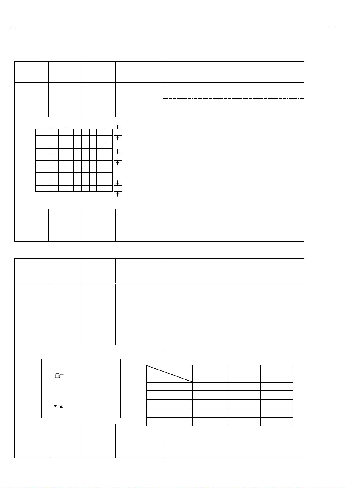
FOCU S ADJUSTMENT
Item
Ad j ust men t
of FOCUS
Measuring
instrume nt
Signal
generator
IF CIRCUIT ADJUS TMENT
Item
Measuring
instrume nt
Test point Adjustment part Description
TP-91 ( B1)
####
TP-E (
)
1. Inp ut a wh ol e black sig na l.
2. Connect a DC voltmeter to TP-91(B1) and TP-E (#).
3. M ake sur e t hat th e v olt ag e is D C 1 16.5±2.0 V.
Test point Adjustment part Description
FOCUS VR
[In HVT]
1. Input a cross-hatch signal.
2. W hil e watch i ng the scre en, adjust the FOCUS VR to make th e
ver ti cal and ho ri zonta l l ines as f in e a nd sha rp as possi b le.
3. M ake sur e t hat whe n th e scre en is d arken ed, the li nes remain in
g ood focu s.
Test point Adjustment part Description
Ad j ust men t
of VCO(CW
Signal
generator
Remote
control unit
VCO (CW)
TOO HIGH
AB OVE REFEREN CE
JU ST REF ER ENCE
BEL OW R EFERE N CE
TOO LOW
AFT AD JUST
VCO ADJUST
FINE
DISP : EXIT
ADJUSTMENT AT THIS POINT IS USELESS
***.**
MHz
** *(* *)
** *(* *)
** *(* *)** *(* *)
** *(* *)
** *(* *)
** *(* *)** *(* *)
ADJUSTMENT POINT
1. VC O
YE LLOW
Do not
TOO HIGH
ABOVE REFERENCE
J US T R E FE RE NC E
B ELO W RE F E RE NC E
TOO LOW
●Please use signal generator which is correct proof about the
sen ding fr eque nc y.
1. Inp ut the PA L f ull col o ur b ar (2 10 .25MH z) si g nal .
2. En ter th e SER VICE MENU.
3. Se lect 1.IF f rom the SERV ICE MEN U.
4. Press 1 key and s elect 1.VCO.
5. Select VCO ADJ US T with MENU ▲/▼ key.
6. Press MENU -/+ key un til the colour of the chara cters TOO
HIGH ch an ges b lue to ye llow. Then g r ad ually pr ess th e MENU
-/+ key u ntil the TOO LOW ch ang es yellow . At thi s t im e, conf irm
th at t he val u e of VCO ADJUST is n ear + 00 .
7. Select AFT ADJUST with MENU ▲/▼ key.
8. Press MENU -/+ ke y until the characters JUST REFERENCE
ch ang es bl ue to y ellow.
9. Press the DISPLA Y key three times to return to normal screen.
20
No. 52023
Page 13

A
V-21DMT3/AV-21D
3
A
A
(
)
(
)
(
)
V-2135TEE/AV-2135EE
V-21DMG3
Item
Ad j ust men t
of DELAY
POI NT
(AGC)
Measuring
instrume nt
Signal
generator
Remote
control unit
DELAY POINT UHF
AGC TA KE-OVER
- / + : OPERATE DISP : EXIT
Test point Adjustment part Description
**
DELAY P OINT
(AGC TAKE-OVER)
1. Inp ut a bl ac k an d wh it e s ign al (col o ur of f).
2. En ter th e SER VICE MENU.
3. Select 1. IF f rom t he SERVI CE M EN U.
4. Select 2 . D ELAY POINT b y pressing th e 2 key on the remote
control unit.
5. Se t th e set ting val u es of the s et ting items as s hown bel l o w t able .
6. Then adjust the MENU - or + key until video noise disappears.
7. T ur n to oth er c h an nel s and m ak e su r e th at the re are n o
irregularities.
Setting It e m Variabl e range Initial se tting v alue
DELAY P OINT
(AGC TAKE OVER)
NT SC 3.5 8
OTHER
0~127
MATSUSHITA
QAU0287-001
45 45 45
35 45 35
MURATA
QAU0185-004
ALPS
QAU0282-001
No. 52023
21
Page 14

A
V-21DMT3/AV-21D3
A
A
(B)
V-2135TEE/AV-2135EE
V-21DMG3
VIDEO / CHROM A CIRCU IT ADJUSTMENT
The setting (adjustment) using the REMOTE CONTROL UNIT is made on the basis of the initial setting values.
The setting values which adjust the screen to the optimum condition can be different from the initial setting values.
Do no t c hange the init ial setting values of the set ting it ems not list e d in “ADJUSTMENT”.
Item
Ad j ust men t
of WHITE
BALANCE
(Low light)
Measuring
instrume nt
Test point Adjustment part Description
Signal
generator
Remote
control unit
V/C PAL
1. CUTO FF
50Hz
/ :SELECT
- / + : OPERATE DISP : EXIT
(R)
(G)
(B)
* **
* **
* **
KEY ASSIGNMENT OF REMOTE CONTROL UNIT
CU TO FF O F F
(H.LINE OFF)
CU TO FF O N
(H.LINE ON)
R. CUTOFF( )
R. CUTOFF( )
▲
▲
R. DRI VE( )
▼
R. DRI VE( )
▼
123
4
7
56
8
9
RGB
1. CUT OFF (R)
CUT OFF (G)
CUT OFF (B)
SCREEN VR
[IN HVT]
G .C UTOFF ( )
B. C UTO FF( )
B. D RIV E( )
B. C UTO FF( )
B. D RIV E( )
G .C UTOFF ( )
▲
▲
▲
▲
▲
▲
1. Inp ut a bl ac k an d wh it e s ign al (col o ur of f).
2. En ter th e SER VICE MENU.
3. S elect 2. V/C from th e SERVICE MENU, the n selec t 1. CUT OFF
(R), (G) and (B) .
4. Set each value to initial setting value with 4~ 9 keys of the
remote control unit.
5. Press the 1 key of th e remote co ntr ol un i t to show th e single
horizontal line on screen.
6. T ur n t he SCREEN VR fully counter-clockwise, then slowly turn it
cl ockw is e to where on e of a red, bl u e or gr e en c o l our is faint l y
vis ible.
7. Use keys 4~9 of th e remote contr o l u ni t an d adjust the oth er 2
col o ur s which e x cept th e ap pea r ed col o ur to where th e s in gle
h oriz o nt al line app ea rs wh it e.
8. Turn the SCREEN VR to where t he sin gle h or iz ont al line g lows
fain tly.
9. Press the 2 ke y to turn off the sin gle hori zon tal line .
10. Press the DISPL AY key t wice to retu rn to the nor mal scr een.
Adjustment it em
R
G
Variabl e
range
-128 ~+127
-128 ~+127
Initial set ting
value
-50
-501. CUT OFF
B -128~+127 -50
Ad j ust men t
of WHITE
BALANCE
(Hi gh light)
Signal
generator
Remote
control unit
2. DRI VE (R
DRI VE ( B)
)
1. Inp ut a bl ac k an d wh it e s ign al (col o ur of f).
2. En ter th e SER VICE MENU.
3. S elect 2. V/C from th e SERVICE MENU.
4. Select 2. DRIVE (R) / (B) with MENU ▼/▲ key, and set each
val u e to ini tial setti ng val u e with 4 and 7 or 6 an d 9 k eys of th e
remote control unit.
5. Use th e keys 4 and 7 or 6 and 9 t o p ro duc e a white scr een
V/C PAL
* **
2. DRIVE
50Hz
/ :SELECT
- / + : OPERATE DISP : EXIT
(R)
* **
22
6. Pr ess the DISPLAY key twice to return to the nomal scree n.
Adjustment it em
Variabl e
range
R -128~+127 +0
2. DRIVE
B
-128 ~+127
No. 52023
Initial set ting
value
+0
Page 15

A
V-21DMT3/AV-21D
3
A
A
V-2135TEE/AV-2135EE
V-21DMG3
Item
Ad j ust men t
of
SUB BRI GHT
Ad j ust men t
of
SUB CONT.
Ad j ust men t
of
SUB
COLOUR ⅠⅠⅠⅠ
Measuring
instrume nt
Remote
control unit
Remote
control unit
Remote
control unit
Test point Adjustment part Description
3. BR IG HT 1. Receive any bro adc ast.
2. En ter th e SER VICE MENU.
3. Select 2. V/C f rom S ERVICE MENU.
4. Select 3. BRI GHT with the MENU ▼/ ▲key.
5. Set the initial setting value with the MENU - / + key.
6. If the brightness is not the best with the initial set value, make
fine adjustment until you get the best brightness.
4. CONT . 1. R ecei v e an y bro adc ast.
2. En ter th e SER VICE MENU.
3. Select 2. V/C f rom S ERVICE MENU.
4. Select 4. CONT. with the M ENU ▼/▲key.
5. Set the initial setting value with the MENU - / + key.
6. If the co ntrast is no t t he best with th e initial s et value, m ak e f ine
adjustment until you get the best contrast .
5. COLOUR [Method of adjustm ent without measuring instrument]
PAL COLOUR
1. R eceive a PAL broa dcast.
2. En ter th e SER VICE MENU.
3. Select 2. V/C f rom t he SERVI C E M EN U.
4. Select 5. COLOUR with the MENU ▼ /▲ key.
5. Se t the initi a l setting value for PAL COLO UR with the MENU
- / + key.
6. If the c o l our i s not th e best with th e i n iti a l s et val u e, mak e fin e
adjustment until you get the best colour.
SECAM COLOUR
NTSC 3.58 COLOUR
NTSC 4.43 COLOUR
1. R eceive a SEC AM br oadc ast.
2. M ake fine ad ju stm en t of SE CA M CO LOUR as previousl y.
1. R eceive a NTS C 3.58MHz br oa dcast.
2. M ak e si m ila r fi n e ad ju stm ent of NTSC 3.58 CO LOU R as
previ ously .
When NTSC 3.58 adjustment completed, NTSC 4.43 will be
automatically set at t he resp ective values.
No. 52023
23
Page 16

A
V-21DMT3/AV-21D3
A
A
))
))
g
V-2135TEE/AV-2135EE
V-21DMG3
Item
Ad j ust men t
of SUB
COLOUR
ⅡⅡⅡⅡ
W
Measuring
instrume nt
Signal
generator
Oscillosc ope
Remote
control unit
Y
Cy
Test point Adjustment part Description
TP-47G/R
TP-E (####)
[CRT S OCKET
PWB]
M
5. COLOUR [Method of adjustm ent using measur ing instrument]
R
(A)
PAL COLOUR
B
(-)
0V
(+)
1. Inp ut a PA L full field colour bar si g nal (7 5% w h it e).
2. En ter th e SER VICE MENU.
3. Select 2. V/C f rom S ERVICE MENU.
4. Select 5. COLOUR with the MENU ▼/ ▲ key.
5. Set the initial setting value of PAL COLO UR with the MENU
- / + key.
6. C on nect th e osc illosc ope be tw ee n TP -4 7G /R and TP-E (#).
7. Adjust PAL C OL OUR to bring th e value o f (A) in the illustration
to + 10V (W - G). ( Volt age value b et we en (W) an d ( G))
G
SECAM CO LOUR
1. Input a SECAM full field colour bar signal (75% white).
2. Set the initial setting value of SECAM COLOUR with the MENU
- / + key.
3. Adjust SE C AM CO LOU R to brin g th e value of
illu str ati on to + 10V(W-G). (Voltage value between (W) a nd (G
(A)
in the
NTSC 3.58 COLOUR
NTSC 4.43 COLOUR
24
1. Inp ut a N TSC 3. 58 full fi e ld colour b ar sign al ( 75 % whi te).
2. Set the initial setting value of NTSC 3.58 COLOUR with the
MENU - / + key.
3. Adjust N T SC 3.5 8 COL OU R to br i ng the val u e of (A) in th e
illu str ati on to + 10V(W-G). (Voltage value between (W) a nd (G
When N TSC 3.5 8 i s set, NT SC 4. 43 will be automatica ll y s e t at t he
resp ec ti ve val ues .
No. 52023
Page 17

A
V-21DMT3/AV-21D
3
A
A
y
g
(B)
V-2135TEE/AV-2135EE
V-21DMG3
Item
Ad j ust men t
of TINTⅠⅠⅠⅠ
Ad j ust men t
of TINTⅡⅡⅡⅡ
Measuring
instrume nt
Signal
generator
Remote
control unit
Signal
generator
Oscillosc ope
Remote
control unit
Test point Adjustment part Description
6. TINT [Method of adjustment without measuring instrument]
TP-47G/R
TP-E (####)
[CRT
SOCKET
PWB]
NTSC 3.58 T INT
NTSC 4.43 TINT
6. TINT [Method of adjustment using measur ing instrument]
NTSC 3.58 T INT
1. Inp ut a N TSC 3. 58 full fi e ld colour b ar signa l (75% white) .
2. En ter th e SER VICE MENU.
3. Select 2. V/C f rom S ERVICE MENU.
4. Select 6. TINT with t he ME NU ▼/▲ key.
5. Set the initial setting value of NTSC 3.58 with the MENU - / +
key.
6. If you ca nn ot get th e best ti n t wi th the in iti al s ettin g va l ue, ma ke
fine adjustment until you get the best tint.
When N TSC 3.5 8 i s set, NT SC 4. 43 will be automatica ll y s e t at t he
resp ec ti ve val ues .
1. Inp ut a NTS C 3.5 8 f ull fi el d colo ur b ar si gna l ( 75% w hi te) .
2. En ter th e SER VICE MENU.
3. Select 2. V/C f rom S ERVICE MENU.
4. Select 6. TINT with t he ME NU ▼/▲ key.
5. Set the initial setting value of NTSC 3.58 with the MENU - / +
key.
6. C on nect th e osc illosc ope be tw ee n TP -4 7G /R a nd TP-E. (#).
7. Adjust NTSC 3.58 TINT to bring the value of (B) in the
illustration +7V(W- Cy). ( Volta ge value be tw ee n (W) and (Cy))
W
B
R
M
(-)
0V
Y
C
G
(+)
NTSC 4.43 TINT
When N TSC 3.5 8 i s set, NT SC 4. 43 will be automatica ll y s e t at t he
resp ec ti ve val ues .
No. 52023
25
Page 18

A
V-21DMT3/AV-21D3
A
A
V-2135TEE/AV-2135EE
V-21DMG3
Item
of SECAM
BL AC K
OFF SET
KEY ASSIGNMENT OF REMOTE CONTROL UNIT
COLOUR
ON
COLOUR
OFF
Measuring
instrume nt
Remote
control unit
Signal
generator
12 3
Test point Adjustment part Description
7.SECAM
BL ADJUST
[Method of adjustment using measur ing instrument]Ad j ust men t
1. Inp ut a SE CAM ful l f ield c olour b ar sign al.
2. En ter th e SER VICE MENU.
3. Select 2. V/C f rom S ERVICE MENU.
4. Select 7. SECAM BL ADJUST with MENU ▼/▲ key.
5. Set the initial setting value with the MENU - / + key.
6. Switch the ①ke y (c ol ou r OF F ) an d ②key (c ol ou r ON ) on the
remote contr ol an d ma ke sur e th at th ere is no colo ur on th e
blac k an d w h it e scr ee n.
7. If the black an d w hi t e s creen is no t b est with th e ini t ial s ett ing
value, make fine adjustment until you g et the best black and
white screen .
8. W hil e w atch i ng th e s cre en, adj us t the val u e t o be the s ame
col o ur b etwee n O N & OFF b y t en key on t he r em ote c ontro l
un it.
9. Pr ess the DISPLAY key twice to return to the normal scr een.
4
7
56
8
9
26
No. 52023
Page 19

A
V-21DMT3/AV-21D
3
A
A
V-2135TEE/AV-2135EE
DEFLECTION CIRCUIT ADJUSTMENT
"
The re ar e 2 m od es of adju stm ent (s ettin g value) ---- -- ① 50 Hz m od e and ② 6 0Hz m od e ----- de pe ndi n g upo n th e kind of s igna ls
(ver tic al freq uenc y 5 0Hz / 60Hz) .
"
When ad j uste d i n mod e ① , mode ② will be automatically set.
The setting (adjustmen t) usin g the REMOTE CONTROL UNIT is made on the basis of the initial setting values.
The setting values which adjust the screen to the opti mum condition can be different fr om the initial settin g values.
V-21DMG3
Item
Ad j ust men t
of V.HEIG HT
&
V. POSIT I ON
Screen
size
92%
Measuring
instrume nt
Test point Adjustment part Description
Signal
generator
Remote
control unit
SU B ME NU 3. D EF
DEF
1. VER. POSITION
50Hz
/ :SELECT
- / + : OPERATE DISP : EXIT
Scre en size
PAL
***
1. VE R. POSITION
3. VE R. HE IG HT
Picture
size
10 0%
1. Inp ut a circle p att ern si gn al.
2. En ter th e SER VICE MENU.
3. Select 3. DEF. from SERVICE MENU.
4. Select 1. VER . POSITION with the MENU ▼/▲ key.
5. Set the initial setting value with the MENU - / + key.
6. Adjust V and V’ t o b e equal with the MENU - / + key a s sh own in
Fig.2.
7. Inp ut a cros s -hatch sign al.
8. Select 3. V . HEIG HT with the MENU ▼/▲ key.
9. Set the initial setting value with the MENU - / + key.
10. As shown in Fig.1, adjust V E R. HE IGH T and m ak e th e vertical
screen size 92% of the pi ctu r e siz e with t he MEN U - / + keys of
remote control unit.
Ad j ust men t
of HOR .
POSITION
Pic ture size 1 00%
Fig.1
Signal
2.HOR. POSIT ION 11. Inp ut a circle p attern si gnal.
generator
Remote
control unit
HH"
V
V'
Fig.2
No. 52023
12. Sele ct 2. HOR POSITION with the MENU ▼/▲ key.
13 . Se t th e ini tia l sett ing v al ue of 2. HOR. POSITION with the
MENU - / + key.
14. Adju st 2. HOR. POSITION to make H= H " as sh ow n in Fig. 2
with the MENU - / + ke y.
27
Page 20
A
V-21DMT3/AV-21D3
A
A
V-2135TEE/AV-2135EE
V-21DMG3
Item
Ad j ust men t
of VER. LI N.
& VER .
SCURVE
Measuring
instrume nt
Signal
generator
Remote
control unit
Fig .3
Test point Adjustment part Description
4. VER. L IN.
5. VER. S CURV E
TOP
CEN TER
BOTTOM
●●●● Whe n the v ertic al linea rity has b ee n dete riorated
remark ably, perform the followi ng steps .
15 . Input a cross -hatch sign al.
16. Sele ct 4. VER. LIN. with the MENU ▼/▲ key.
17. Set the initial setting value of 4. VER LIN. with the MENU - / +
key.
18. Sele ct 5. VER. SCURVE with the MENU ▼/▲ key.
19. Set the initial setting value of 5. VER. SCURVE wit h t h e ME NU
- / + key.
20. Adju st 4. VER. LIN. and 5. VER. SCURVE so t hat th e sp aces
of each lin e as sh own i n Fi g. 3 on TOP, CENTER and
BOTTOM become uniform.
.
Make su r e th at th e a djus t ment is pr o per l y do ne on t he sc r e en of
60 Hz mode .
[NOTE]
"
Adjust to make both 50Hz & 60Hz are the same v. size and
fine straight line.
"
When ad j ust aga in, adju st 5 0H z m ode fi r s t.
"
When adjust in 60Hz mode, only 60Hz mode is adjust.
VSM PRESET SETTING
Item
Setting of
VS M
PRES ET
Measuring
instrume nt
Remote
control unit
TINT
COLOUR
BRIGHT
CONT.
SHARP
/ :SELECT
- / + : OPERATE DISP : EXIT
Test point Adjustment part Description
TINT
COLOUR
BR IG HT
CONT .
SHARP
1. En ter th e SER VICE MENU.
2. Select 4. VS M PRESE T from the SERVICE MENU.
3. Se lect BRIG HT w ith th e P ICT URE MODE ke y.
4. Adjust t he M EN U ▼/▲ an d M ENU - / + ke y to bring the s et
val u es of TI NT
tabl e.
5. R esp ectively sel ect the VSM PR ES ET m ode f or SOFT and
STANDARD, and make similar adjustment as in 3 a bove.
~~~~
SHARP to the values shown in the below
•••• VS M PRESET
BRIGHT
**
**
**
**
**
VS M
Setti ng It em
TINT +15
COLOUR +15
BRIGHT + 15
CONT +30 +15 +11
SHAR P +15
BRIGHT STA NDARD SOFT
←
←
←←
←←
←
+12
28
No. 52023
Page 21

A
3
A
A
PURITY / CONVERGENCE ADJUSTMENT
PURITY ADJUST MENT
1. Demag ne tiz e CRT w it h the dema gneti zer.
V-21DMT3/AV-21D
V-2135TEE/AV-2135EE
V-21DMG3
2. L oose n th e re tain er scr ew of the d efl ec tion yok e .
3. Remove th e w ed ge s.
4. Inp ut a g r een rast er sign al from the sign al generat or , and tur n
th e scr e en to g r een r aste r.
5. Move the deflection yoke backward.
6. Br ing t he long l ug of th e p ur i ty m agn ets on the short lu g a nd
p osit ion t hem hor i zon tal ly. (Fi g. 2)
7. Ad ju st t he ga p be tween t wo l ug s so that the G RE EN R AS TER
will come into the center of the screen. (Fig.3)
8. M ove the d eflect ion y oke for w ar d, a nd fi x th e pos itio n of th e
deflection yoke so that the whole screen will bec ome green.
9. Ins ert th e we dg e t o the t op side of the def lect io n yo ke s o th at it
will not move.
CR T
#
WEDGE
DEFLECTION
YOKE
P
46
P / C
MAGNET S
P/ C MA GN ETS
P : PURITY M AGN E T
4 : 4 P OLES ( con vergence m agn ets)
6 : 6 P OLES (con v er gen ce magn ets )
Fig.1
PURITY MAG NETS
10 . Inp ut a cross hat ch sig na l.
11 . Ve rif y that th e scr e en is horiz on tal.
12 . Inp ut r ed and bl ue r as t er signals, and make su r e tha t pur i ty is
prop er ly ad juste d.
Long lug
Short lug
(FRO NT VIEW )
Bring the long lug over the short lug
and position them horizontally.
Fig.2
GREEN RASTER
CEN TER
Fig.3
No. 52023
29
Page 22

A
V-21DMT3/AV-21D3
A
A
V-2135TEE/AV-2135EE
V-21DMG3
STAT IC CONVERGENCE ADJUSTMENT
1. Inp ut a cr oss hatc h sig nal.
2. Usin g 4 - po le c on verge nce magn ets , ov e rla p t he red a nd bl u e
lines in th e c en ter of th e scr een (Fi g. 1) a nd tu rn the m to
mag ent a (r ed/ blue ).
3. Us ing 6 - pol e conver ge nce ma gn ets, over l ap the
mag ent a( re d/b lue) a nd g r een li nes in t he cen ter of the sc r een
an d t urn t hem t o whit e.
4. Rep eat 2 and 3 ab ove, an d ma ke b est c onve r ge nce.
DYNAMIC C ONVERGENCE ADJUSTMENT
1. Move th e d ef lec tion yok e u p an d d own and o v er lap th e lin es in
the periphery. (Fig . 2 )
2. M ove the def l ecti on yoke left to ri gh t and over lap t he l in es in the
p erip hery. (Fig. 3)
3. Rep eat 1 and 2 ab ove, an d ma ke b est c onve r ge nce.
(FRO NT VIEW )
(FRO NT VIEW )
BLUE
GREEN
RED
Fig.1
GREEN
BLUERED
RED
GREEN
BLUE
●
After ad justm ent, f ix the wedge at the original p osition.
Fas t en the retainer screw of th e def lecti on yoke .
Fi x the 6 magn ets with g lue.
(FRO NT VIEW )
GREEN
RED
BLUE
GREEN REDBLUE
Fig.2
Fig.3
BLUE
GREEN
RED
RED
GREEN
BLUE
BLUE
GREEN
RED
30
No.52023
Page 23

BLOCK DIAGRAM [AV-21DMT3, AV-2135TEE]
IF
TU001
TUNER
Q102
IF AMP
AV-21DMT3 / AV-21D3
AV-2135TEE / AV-2135EE
SF101
SF102
AV-21DMT3
AV-2135TEE
AV-21DMG3
AV-21DMT3 / AV-21D3
AV-21DMT3
AV-2135TEE / AV-2135EE
AV-2135TEE
AV-21DMG3
AUDIO AMP
AUDIO
2
IC651
SP
OUT
8
SP
REAR
VIDEO
IN
AUDIO
VIDEO
OUT
AUDIO
IC702
MEMORY
SCL
SDA
37.38
SCL
SDA
3.58/
OTH
IC701
MICRO COMPUTER
TDATA
TCLOCK
20.36
IC821
TEXT
HEAD
SP
Q103
SW
SCL/SDA
25
18.19
SAW
30
AUDIO
OUT
IC301
ECO
REMOCON
KEY
1 CHIP DECODER
IND.
R / G /B
IC421
OSD
RGB
30.31.32
IC371
RGB.SW
6.7.8
EXT
RGB
VIDEO
IN
24
VIDEO
OUT
36
AUDIO
IN
RGB
10.11.12
29
H.OUT V.OUT
42
46
V .OUT
VERT.OUT
PHONE
FRONT
IN
VIDEO
AUDIO
CRT SOCKET PWB
RGB
DRV
V01
CRT
AC IN
POWER SW
F901
No.52023
LF901
D901
RECT
IC921
POWER
REG.
T921
SW
TRANSF.
IC971
9V REG.
2-3 2-4
REG.
H.OUT
IC972
5V REG.
Q522
H.OUT
REG.
MAIN PWB
B1
No.52023
T522
HVT
DY(V)
DY(H)
DEF.YOKE
FOCUS
SCREEN
EHV
Page 24

BLOCK DIAGRAM [AV-21D3/D, AV-2135EE, AV-21DMG3, AV-21DMG3/-A]
TU001
IF
TUNER
Q102
IF AMP
AV-21DMT3 / AV-21D3
AV-2135TEE / AV-2135EE
AV-21D3
AV-2135EE
AV-21DMG3
AV-21DMG3
SF101
SF102
AV-21D3
AV-21DMT3 / AV-21D3
AV-2135EE
AV-2135TEE / AV-2135EE
AV-21DMG3
AV-21DMG3
IC651
AUDIO AMP
AUDIO
2
SP
OUT
8
SP
REAR
VIDEO
IN
AUDIO
VIDEO
OUT
AUDIO
IC702
MEMORY
SCL
SDA
37.38
SCL
SDA
3.58/
OTH
IC701
MICRO COMPUTER
HEAD
SP
Q103
SW
SCL/SDA
25
18.19
SAW
30
AUDIO
OUT
IC301
ECO
REMOCON
KEY
1 CHIP DECODER
IND.
R / G /B
IC421
VIDEO
IN
24
VIDEO
OUT
36
AUDIO
IN
RGB
10.11.12
29
H.OUT V.OUT
42
46
V .OUT
VERT.OUT
PHONE
FRONT
IN
VIDEO
AUDIO
CRT SOCKET PWB
RGB
DRV
V01
CRT
AC IN
POWER SW
H.OUT
Q522
H.OUT
REG.
F901
LF901
D901
RECT
IC971
9V REG.
IC972
5V REG.
REG.
T921
IC921
POWER
REG.
SW
TRANSF.
B1
MAIN PWB
No.52023 No.52023
2-5 2-6
T522
HVT
DY(V)
DY(H)
DEF.YOKE
FOCUS
SCREEN
EHV
Page 25

AV-21DMT3 / AV-21D3
AV-2135TEE / AV-2135EE
CIRCUIT DIAGRAMS MAIN PWB CIRCUIT DIAGRAMS (1/2) [AV-21DMT3, AV-2135TEE]
AV-21DMT3
AV-2135TEE
AV-21DMG3
AV-21DMT3 / AV-21D3
AV-21DMT3
AV-2135TEE / AV-2135EE
AV-2135TEE
AV-21DMG3
FRONT
REAR
A_IN
A_IN
V_IN
V_IN
A_IN
V_OUT
A_OUT
Q701
J004
CEMN065-002
QNN0281-002
OR
J003
CEMN065-001
OR
QNN0281-003
J002
QNN0384-001
R731
4.7k
C729
180p
CH
1
0
7
L
BUS_FREESCL1
R827
1k
C822
N
E
V
/E
D
D
O
0.5V
INVERTER
R835
1.8k
INVERTER
R383
27k
D373
*4
C318
100p
9V
.6
5
.01
C
N
R828
2.7k
C833
68p CH
0V
Q821
Ys SW
0.2V
V
5
K703
K704
*2
Q822
MENU
S705
QSW0619-003Z
R730
10K
BW
BW
Z
6
R
5
-
J
4
4
2
L
Q
Q
R705
220
L821
NQL092K-4R7X
3.3V
C
.3
3
N
D
D
V
K
C
O
L
C
T
NCN
4V1.7V
C835
220p CH
R834
4.1V
*1
R385
12k
R372
6.8k
Y374
X
W
P
_
B
T
S
W
P
_
B
T
S
SDA2 SCL2
4.7
S
S
V
C
0.1V
39k
0.1V
R849
15k
S
Y
_
D
S
O
D
C
N
C
G
V
_
_
A
A
D
C
N
C
V
G
_
_
A
A
0.1V
R714
4.7k
R720
4.7k
R713
4.7k
R712
4.7k
R704
220
PIC_MUTE
R832
220
TRESET
R844
X
R845
4.7k
C
C
N
N
H
T
/O
A
T
T
A
X
E
D
T
T
0V4V
Q824
INVERTER
0.5V
R837
39k
47kR836
C834
33p
C849
.01
Y
A
R
_
X
F
Y
F
A
R
/O
_
N
X
O
_
P
D
N
G
4.9V
4.9V
C709
.01
R738
10k
C722
100p CH
0V
Q702
*1
SW
L
C
T
*1
INVERTER
LINE_V
CH
TEXT/OTH
F
F
T
/O
O
N
R
O
_
.P
P
A
T
O
R
.P
A
T
c
U
c
V
O
4.9V
4.1V
C719
1/50
AT24C08-21DMG3
SDA
S
C
NP
VDD A0
4.9V
4.7V
R797
15k
2
2
H
T
/O
T
A
X
R848
D
E
T
T
0
0
C843
2
2
.01
5
2
8
R
Q825
*3
3.8
V
0.1
V
R838
10k
P
B
F
P
C
B
C
F
V
_
H
MEMORY
R739
C
C
V
_
H
IC704
PIC-47143SY
REMOCON RECEIVER
D701
IC702
VSS
A2
L
A1
10k
Q703
*3
SW
0V
R742
56k
C724
56p
SDA1
SCL1
2
2
2
D795
C
T
T
N
U
U
Y
O
O
S
_
_
_
H
V
V
T
T
V
C
9
U
U
N
O
O
Y
_
_
S
V
_
H
V
R703
3.9k
5.4V
Q709
*2
P
C
T
F
A
BW
BW
X
BW
1
L
C
S
R701
5.6k
L78LR05E-MA
5V REG&RESET
IN
C705
470/16
1
0
W
7
B
P
C
R
M
0
O
7
W
2
3
-
3
2
J
7
9
7
R
3
2
0
L
!
R
Q
W
P
_
B
T
S
R307
1.2k
R308
1.8k
1
A
D
S
R793
R792
220
D794
X
R791
220
10/50
D
C
C706
220
CN00C
SW
5V
C701
IC703
.01
D731
2
L
C
S
X
D
N
G
E
T
U
M
_
IC
P
*4
MA3091/M/-X
FBP
P
B
F
P
P
V
220R301
C301
.012
4.7/50
2
A
D
S
E
E
R
F
_
S
U
B
*4
V_SYNC
Y161
Y975
Y001
Y002
X
2-7 2-8
T
E
S
E
R
100/16
R306
220
A
D
S
L
C
S
C302
R302
4.7k
R794
220
R795
220
C707
C308
.01
D303
4.9V4.9V4.9V14.4V
R702
6.8k
T
U
O
V
5
S
S
V
1
C
P
.A
C
10/50
R341
3.3K
XD791
XD792
XD793
8
0
7
C
C341
D341
C309
*4
SP01
QAS0086-001
MAIN PWB
SCG-1315A-H2
S3 S4
CN10S
!
J005
HEADPHONE
15.1V
R655
47k
Y976
X
C504
X
C402
X
C437
.1
t
u
o
V
G
T
X
E
N
O
G
C367
C366
1/50
1/50
BP
C307
470/16
CHGC05-340-G
*
R661
270
1/2W
D655
R667
100 1/2W
D654
*7
Q653
*2
15V
MUTE
100/25
-2.2V
D657
*4
CE41651-001Z
R503
6.8k
C503
C502
TF
10/50
.01
C316
10/50
3.4V3.7V1.1V3V5V4.9V4.3V0.6V 4.2V
1
g
th
C
o
lin
F
o
p
T
u
A
o
H
IO
c
W
e
D
A
D
U
S
A
)
V
(9
c
c
T
U
B
V
J
T
O
_
C
X
V
R
E
3
4
0
0
0
0
3
3
1
R
R
N
O
B
BP
R
CN00T
PC701
P1241-04
SENSORECO
QNS0197-001
R662
270
1/2W
0
/1
0
0
0
1
LB
D305
AK04-T2
D501
*6
V_OUT
R401
.01
10k
C401
.47
TF
]
P
C
V
C
G
[5
S
D
r.A
D
e
V
V
s
L
R
Y
T
T
C
X
X
B
E
E
A
4.9V0V3.3V6.2V4.2V
N
O
R
C365
1/50
BP
C306
.01
L
B
A
CN00S
X
XY655
BWY654
BWY653
DC ATT AUDIO OUT
1
c
c
IN
V
*4
C664
100/16
C655
10/50
N
C656
1/50
BP
D656
*4
R656
8.2k
C657
C665
.01
R657
R658
2.2k
2.2k
Q302
9V
*1
BUFFER
C321
4.2V
12p
CH
X302
C
D306
C
1001/2W
V
_
T
H
U
O
W
H
_
B
C
H
1
0
0
0
1
5
0
/1
5
R
2
0
0
7
C
5
4
0
p
R
1
0
3
3
2
0
C
2
3
D
6.2V0.9V
t
c
z
u
c
H
o
V
M
H
H
8
.5
3
IC301
NN5198K
DECODE
D
N
T
T
U
U
G
J
O
O
_
C
_
V
B
G
C303
5
0
0
0
10p
0
0
3
1
1
R
CH
X301
!
QAX0705-001Z
.2
8
Z
2
R
3
0
-8
C112
1
K
L
4
47/25
4
2
L
Q
Q
V
B
D
G
9
N
SF102
G
*
SAW FILTER
C109 X
*
AN5265 AUDIO AMPIC651
C663
.001
4.9V
IN
_
c
n
y
s
H
Z
H
M
3
.4
4
.47/50
MUTE
R665
10k
k
1
4
1
3
R
k
1
3
1
3
R
1
.0
1
1
3
C
C113
.0047
L
O
V
N
C304
0.6V
TF
NC
LINE_V
P
B
0
/5
7
.4
2
1
3
C
0
2
1
3
R
4.2V4.3V2.7V
IN
_
c
n
y
s
/V
Y
f
re
L
L
P
M
A
C
E
S
S5
CN11S
X
L
O
B
V
F
10.5V
0.3V5.5V12.4V 22.1V10.9V10.7V
R666
100
C659
4.7/50
D653
*4
R654
22k
0V
Q652
0.3V
*1
SW
Q651
*1
SW
R321
1.5k
Q301
BUFFER
*2
4.2V
R323
10k
R327
4.7M
C313
3.3/50
C322
.027/25
R322
2.7k
2
T
C
U
P
O
_
.A
O
C
E
ID
V
f
re
L
)
L
V
E
9
(
B
c
c
M
V
A
IF
C
E
/S
S
V
C305
.47/50
C114
.01
C111
X
R118
R116
*
X
Q103
*
SW
R660
15k
R653
330
C653
10/50
0V
C314
.01
.047/25
4.6V4.2V8.5V
]
V
[5
c
c
V
W
A
S
2.7V3.8V9V4.1V2.8V3.1V3.1V3.2V9V4.9V4.9V
6
2
3
C
D
N
G
Y301
Y302
C317
C110
SCG-1407A-H2
!
R668
2
T
U
O
C658
220/25
R659
4.7
1/2W
R651
4.7k
C651
OPT
100/16
x
0
1500p
t
)
u
V
o
(9
t
c
c
e
D
V
A
IF
V
M
O
R
H
C
D
N
G
IF
W
/S
A
V
S
%
5
p
0
2
2
XL104
SF101
SAW
FILTER
0
R117
C108
470/16
C315
C162
5
1
1
C
2
2
1
C
c
c
A
C654
C652
.047
D102
*
LINE_A
0.47/50
4.1V9V
is
s
a
h
p
m
e
e
D
IN
_
S
S
Q
1
.0
1
.0
R114
*
R652
1k
NRSA63J-102X
D301
*5
C323
l
e
v
e
L
k
c
la
B
t
u
o
C
G
A
F
R
0
2
2
1
2
1
R
C121
.01
*
5.6
QRT029J-5R6
D652
*7
E
T
U
M
_
A
AUDIO
10/50
3.9V3.2V
T
IN
U
_
O
IO
_
D
IO
U
D
A
U
A
t
u
o
o
IN
T
/C
F
V
A
1
.0
6
D302
1
1
*5
C
C107
.0047
R115
*
V
2
3
R324
1k
C324
C117
D651
*4
R664
6.8k
T
D
C
O
N
C
R
G
V
_
.P
_
A
A
A
3.4V3.6V
t
u
to
e
D
Q
C
P
A
V
3.4V2.9V3.2V3.6V1.8V1.8V2.7V
R161
Q102
*10
AMP
C161
*
0
2
1
R
.47/50
*
CF161
*
C119
C120
120p
0
CH
9
3
C325
10/50
SF122X
QAX0325-001
SAW FILTER
QQL244J-2R2ZL101
R111
9V
1.5V
R112
R113
R163
Y160
CF162
N
BP
R160
180
*
100
R325
X
IN
_
IF
S
C
G
A
_
IF
.22
TF
R326
100
C106
.0047
C105
.0047
VIDEO
*
*
X
X
2.2V
R166
R109
6.8k
R110
2.7k
(1/2)
(AV-21DMT3)
(AV-2135TEE)
IC301 36
2
C164
4
6
*
*
1
R
Q161
*
AMP
2
R165
6
*
1
*
R
5
6
*
1
C
*
R159
180k
R158
X
C103
47/25
C104
R103
.0047
CF103
X
10
CF102
3.58/OTH
IC301
3
NOTE
*1:
2SD601A/QR/-X
*2:
2SB709A/QR/-X
*3:
UN2212-X
*4:
MA111-X
*5:
MTZJ9.1B-T2
*6: MTZJ6.8C-T2
MTZJ12C-T2*7:
UN2112-X*8:
QQR0621-002Z*9:
*10: 2SC5083/L-P/-T
C166
DIFFERENCE LIST(*PARTS)
*
CN10S
SF102
CF161
Q103
Q161 *1
D102
Y160
R112
R114
R115
R117
R118
R161
R162
R163
R164
R165
*
R166
C109
C161
C164
C165
C166
!
IC701
21DMT3
SCG
-1315A-H2
WJK0136
-001A
QAX0731
-001
QAX0642
-001Z
*3
MA859
-T2
BW
NRSA63J
-220X
NRSA63J
-472X
NRSA63J
-222X
NRSA63J
-0R0X
NRSA63J
-222X
NRSA63J
-102X
NRSA63J
-122X
NRSA63J
-222X
NRSA63J
-221X
NRSA63J
-220X
NRSA63J
-821X
NCB31HK
-472X
NCB31HK
-103X
NCB31HK
-103X
NCB31HK
-103X
NCB31HK
-104X
MN18732
87JJ1
2135TEE
SCG
-1407A-H2
WJK0136
-001A
QAX0666
-002
X
X
X
BW
X
NRSA63J
-100X
X
X
X
X
X
X
X
X
X
X
X
X
X
X
X
MN18732
87JK1
IC301
39
2
AFT
8.2
L001
QQL244K-8R2Z
C003
x
C004
470/16
5V REG
IN
IC001
X
IC301
L002
X
D
T
N
U
G
O
C005
.1
TF
11
R001
X
C009
X
X
10
3.4
QAU0282-001
D001
MTZJ33A-T2
C006
X
R004
56k
2.5
!
R102
BWK001
C002
.01
3.4
75
220R002
220R003
C007
IC301
TU001
10/50
X
C001
42
C008
4.7/50
32.6V
4.9V
4.3V
4.2V
1.8V
0V
NC
NC
12
46
2.2
IF
BTPS(32)
LOCK
5V
BM
SDA
SCL
AS
BT
AGC
No.52023
QSW0619-003ZS703
R736
82k
1k
C
N
1
L
C
S
H
C
6
1
7
p
0
C
8
1
Y705
BW
5
0
1
2
7
2
R
L822
R
_
NQL092K-4R7X
T
X
0
E
/5
T
.3
3
6
3
C846
8
C
.01
k
100/16
.3
3
0
5
8
R
2.4V
V
.5
2
A
D
D
V
C
N
R859
47k
4.9V
1.5V
R842
22k
4.7kR384
N
E
V
/E
D
D
O
R856
X
N
E
V
/E
D
D
O
0V
4.9V4.4V4.4V4.7V4.7V
C826
4.9V
E
E
R
F
_
S
U
B
D
D
V
4.7
C823
C821
.01
A
S
S
V
C
N
2.2V
C711
.01
R376
5.6k
.01C730
33p
CH
R373
Q372
0V
Ys SW
R375
R841
3.3k
S
Y
_
T
X
E
T
1k
*1
15k
R727
15k
180p CHC728
2
L
C
S
1
C
S
O
1
L
A
T
X
C
N
CH+ CH-
QSW0619-003ZS704
4.8V
4.9V
2
N
A
O
D
C
S
O
M
E
R
2
C
S
S
S
O
V
X701
QAX0307-001
C710
100/16
C824
C825
39p
1/50
CH
1
Z
2
1
8
0
X
-0
9
6
6
0
X
A
Q
4V0.3V0.8V
2
T
L
S
A
R
T
X
S
S
V
H
0.1V0.5V0V2.4V0.7V3.3V0V2.4V
R846
10k
4.9V
R833
8.2k
Q373
3.7V
*1
SW
0V
D372
*4
Q371
*1
0V
R374
4.7k
VOL+ VOL-
R726
4.7k
X
7
3
7
R
]
W
O
[P
D
E
L
C
N
5
2
7
R
X
560
2.4V
V
.5
2
D
D
V
V
.3
3
D
D
V
C844
.01
B
_
D
S
O
3
7
X
3
Y
1.2V1.2V1.3V1.3V
1.3V1.2V1.2V1.2V 1.2V
k
0
0
1
QSW0619-003ZS701
C721
.033
k
0
0
1
T
F
IN
A
O
C
E
C
N
Y
T
S
S
_
V
R
4.9V
k
1
TCL
S
Y
_
T
X
E
T
0
2
8
5
5
8
R
C852
R854
.01
3.3k
B
S
_
Y
_
D
S
D
S
O
O
!
SDA5553-V006
.5
2
A
S
B
D
V
D
C
V
L824
4.7
NQL092K-4R7X
C831
QFV71HJ-104Z
QQL244K-8R2Z
R862
R861
10k
B
_
T
X
E
T
3.2V
AB2B1BOROVDD
1
k
8
0
3
5
R
1
QSW0619-003ZS702
3
1
1
7
.0
C
B
_
T
X
0
E
/5
T
.3
3
8
3
8
C
0
2
8
3
5
8
R
IC821
TEXT
L828
4.7
390
R728
1k
2
1
Y
Y
E
E
K
K
K
C
1
O
A
L
D
C
S
T
H
C
7
1
7
p
C
0
8
1
1
W
0
B
7
K
6
0
1
2
7
2
R
SDA1
G
_
T
X
0
E
/5
T
.3
3
7
3
8
C
0
2
8
1
5
8
R
R852
3.3k
0.1V0.2V0V
0.2V
G
_
D
S
O
A
S
C
S
V
N
C832
.01
Q826
*10
INVERTER
R860
100
R843
100kR379
150kR382
CB
R729
R
_
D
S
O
470
D704
SLR-342VR-T16
POWER
R773
L
O
E
V
T
R749
U
4.7k
M
R771
_
820
A
X
k
0
X
0
5
7
R
D707
*4
C
N
F
F
/O
N
O
_
P
6
2
X
7
C
F
F
/O
N
O
_
P
EF801
C
N
C
S
/S
C
N
Y
S
V
0V
10kR857
!
IC822
1W OMR
R811
LINE_V
C811
10/50
LINE_A
A_MUTE
9
1
7
R
C725
220
R748
100
D706
C738
X
2
0.7V
3
1
7
3
X
X
7
C
C
0V
E
T
U
M
_
A
K
C
O
L
k
1
X
Y801
X
C
N
C
N
56
4.2V 0.1V 2.4V 0V 4.9V 2.9V 4.9V 4.9V 4.9V
L
T
T
F
F
X
E
O
E
S
V
/O
T
E
N
R
O
C
L
A
H
C
H
T
N
T
/O
Y
8
/O
S
_
.5
.5
3
4
H
8
1
1
7
.0
C
C720
.01
C723
R734
R722
X
R706
H
T
/O
8
.5
3
I/II
Y802
BW
0
EF802
X
C
C
C
N
N
N
C
C
C
N
N
N
L825
NQL092K-4R7X
L826
NQL092K-4R7X
C847
4.7/50
8
4
1
C850
8
.0
X
C
3
1
1
1
5
6
4
9
7
7
R
R
TRESET
TDA
0.3V
C712
.01
8.1V
4.1V
Y704
0
Q803
2SC1815/YG/-T
BUFFER
R806
1/2W
R816
680
0V
C812
4.7V
0V
H
T
/O
T
X
E
T
T
C
E
T
O
R
P
4.9V 4.9V 4.9V4.1V0V4.9V1.7V
T
O
R
.P
A
ODD/EVEN
PQ2L3252MS-X
VIDEO
AUDIO
R810
QRG01GJ-560
4.8V
270
R817
4.7k
X
TEXT/OTH
D801
*4
C727
X
R747
0
Q704
X
SW
R746
10k
Y
A
R
_
X
X
R717
SW
X
XJ006
C841
1500p
R802
75
C842
X
C805
220/16
C806
R807
470/16
68
R815
180
1/2W
Q804
*1
SW
X
R740
3.9k
X
/V
V
T
I/II
7
3
X
7
C
X
X
560
C743
10/50
100/16
C
N
C
N
2.4V
4.9V
G
R
_
_
D
D
S
S
O
O
TEXT_R
GO
TEXT_G
4.9V
C744
.01
C
N
!
IC701
MICOM
s
Y
_
D
S
O
3
4
3
3
X
7
7
C
C
8
9
0
k
0
7
1
7
R
R
S
Y
_
D
S
O
NQL092K-4R7X
C853
C854
C827
.01
C
N
C
N
4.7
C845
.01
4.7
3.3V 2.5V
!
IC822
REG.IC
IN GND
Y371
X
R1 R2
TIMER
R721
10k
D705
SLR-342DU-T16
Q710
SW
R772
820
Q708
*3
SW
4.9V
R741
560
]
C
D
IM
N
N
G
[T
D
E
L
*
B
G
R
_
_
_
D
D
D
S
S
S
O
O
O
0V0V0V0V
6
3
5
7
3
X
X
7
C
C
0
1
k
k
k
1
1
7
7
.7
.7
.7
4
R
4
R
4
R718
560
R707
C741
10/50
C742
B
G
R
10/50
_
_
_
D
D
D
S
S
S
O
O
O
L823
L827
4.7
4.7
NQL092K-4R7X
.01
3.3V
S
V
C
S
N
.3
V
3
D
D
V
V
.5
2
D
S
C
D
S
N
V
V
4.9V
NR
C855
10/50
C830
C856
150p CH
.1
O
O
R
B
1
7
X
3
C
4.9V
IC371
TC4053BP/N/
RGB.SW
G1 GO G2 INH VEE VSS
2
7
X
3
Y
0
7
8
k
k
8
7
7
0
0
3
3
3
5
0
R
R
R
1
1
No.52023
Page 26

MAIN PWB CIRCUIT DIAGRAM (2/2) [AV-21DMT3, AV-2135TEE]
BLU
T3.15AH
QMF51E2-3R15J4
R901
QRF104K-3R9
QCZ9015-102
C905
250VAC
C909
120P 400V
C930
X
K901
*8
D933
MTZJ16C-T2
D921
*5
2200p 250VAC
QRZ9046-825Z
BRN
!
S901
QSW0750-001
!
POWER SW
F901
DEG RELAY
RY971
X
!
C991
.001 250VAC
QCZ9079-102
!
C992
.001 250VAC
QCZ9079-102
C904
250VAC250VAC
!
D901
G2SBA60
C929
!
.01
630V
QFKA2JK-103
R928
68k
QRL039J-683
3WOMR
3
-T
0
1
0
0
-5
3
9
M
0
D
1
P
G
K902
R
*8
R933
4.7
1/2W
D925
*5
!
C993
QCZ9079-222
!
R991
8.2M
LIVE ISOLATED
PW
CN0PW
QGAB80F1-02
ISOLATED
Q973
X
T921
QQS0161-001
K943
K942
RU3YX-LFC4
K941
*8
(())
D973
X
!
*8
RGP10J-5025-T3
*8
560p 2kV
QCZ0364-561
RU3AM-LFC4
DEG-COIL
L01
QQW0006-001
CNDEG
QGZ5004C1-02
(AC110-240V)
QMPR340-165-K2
OR ERZV10V621CS
!
TH901
QAD0121-9R0
OR
QAD0119-9R0
Y904
BW
Y905
BW
R904
X
!
IC921
STR-W5753A/F5
Drain
OVP
TSD
OSC
Source
DRIVE
FB/OLP
OCP/INH
Y902
BW
QRM034J-R22
R906
100k 2WOMR
QRL029J-104
137.5V
!
2kV
C931
NC
QCZ0364-681
0.1V
0
4
GND
/5
2
9
.7
4
C
16.9V
Vcc
C922
.1
D929
*9
1V
2
p
3
0
9
2
C
2
D928
*7
QFLC1HJ-332Z
MAIN PWB
SCG-1315A-H2
(AV-21DMT3)
SCG-1407A-H2
(AV-2135TEE)
POWER CORD
!
VA901
QAF0052-621
!
C901
QFZ9078-224
!
LF901
QQR0527-002
Y903
!
C910
275VAC MF
QFZ9078-473
! !
C907
.001 .001
QCZ9015-102
R923
R921
2.2
100k 2WOMR
1/2W
QRL029J-104
R922
2
-T
1/2W
A
6
3
J
7
Z
2
T
9
D
M
C925
47/35
TF
C926
3300p
(2/2)
LIVE
MFAC275V
BW
!
.001
QCZ9015-102
!
QEZ0199-127
R903
220
R934
68k
D931
*4
R935
3.9k
1/2W
R985
X
R986
X
R987
X
ICP-N25-Y
D943
C944
QCB32HK-222Z
D942
ICP-N75-Y
1000/25
QEHR1EM-108Z
C941
D941
(())
C972
X
D974XR988
X
C947
QCB32HK-222Z
CP981
!
QQL244J-4R7Z
CP
!
CP
CP982
C945
QEZ0203-107
Y961
L943
4.7
C948
1000/25
QETN1EM-108Z
C949
NDC31HJ-471X
L942
QQL244J-4R7Z
C946
1000/25
L941
82
QQL26AK-820Z
C942
100/160
470p
AV-21DMT3 / AV-21D3
AV-2135TEE / AV-2135EE
W
D
P
C
N
_
C
B
G
V
_
T
_
B
A
S
L
A
Q975
X
R976
12
2WOMR
C976
220/25
R979
33
3WOMR
C978
220/25
R978
47k
R977
1.2k
1/2W
*3
SW
R961
X
Q962
11.4V
0.1V
Q961
X
BA17809T
11.8V
BA17805T
2SA966/OY/-T
15.4V
14.6V
X
R962
IC971
REG 9V
IC972
REG 5V
Q974
3.9V
BW
4.7
CN0S2
Y503
X
Y973
X
0
H004
X
SW
15.2V
C971
9V
R974
2.2k
X
R963
R964
4.9V
AV-21DMT3
AV-2135TEE
AV-21DMG3
C
C
V
_
H
Y972
X
R965
X
X
C961
X
X
C977
220/16
C979
220/10
Q521 B
1
STB
ON
R984
X
R983
X
D986
X
R982
Q982
X
SW
R981
NOTE
*1
2SD601A/QR/-X
:
*2
2SB709A/QR/-X
:
*3
UN2212-X
:
MA111-X
*4 :
*5
:
RGP10J-5025-T3
:
1SR124-400A-T2
*6
*7 :
MTZJ3.3A-T2
*8 : QQR1113-001Z
*9
:
MTZJ5.6A-T2
BUS WIRE
BW
: : X NON MOUNT
(OPTION)
F
F
T
/O
Y
O
N
A
R
O
R
.P
_
_
V
V
A
9
P
5
D983
X
X
*4
D982
*4
Q981
X
X
SW
D985
X
C981
X
AV-21DMT3 / AV-21D3
AV-21DMT3
AV-2135TEE / AV-2135EE
AV-2135TEE
AV-21DMG3
N
E
C
T
U
O
V
_
2
3
H
V
T
N
/E
U
Y
D
L
P
S
O
D
B
_
_
B
F
O
A
V
V
IC421 5
50
IC421 3 6
25
R421
R422
X
4.7k
R423
0
D424
X
R424
0
R425
C422
3.3k
X
V_OUT
4.9V
Q402
R524
R525
2WOMR
R980
1.5k 2WOMR
QRL029J-152
20
Y971
X
B1
OKNG
4.9V
0V
SW
Q572
*1
*1
SW
0V
DTC124ESA-T
X
18
R531
330
Q521 C
CHT32KK0-22-N
MTZJ7.5S-T2
R578
10k
D562
C561
X
X_RAY PROTECTOR
R436
82k
D427
MTZJ27B-T2
5.5V
Q401
V.NECK
C523
47/25
Q521
2SC2655/Y/-T
H DRIVE
R532
W-B
100/160
QEZ0203-107
D571
C572
47/25
X
R565
TP-E
( )
0.2V
1k
2
C531
X
R443
1/2W
C436
.33
Q522 B
FOR TEST
C427
100/35
R426
0
C424
QFLC2AJ-103Z
1
TF
D425
*4
C429
10/50
9.7V
R577
3.9k
R566
X
1
2
E
_
Y
Y
A
A
P
T
R
R
_
_
X
X
IC421
24.7
3.7V
.01
R453
2.7k
T501
QQR1244-001
R526
1/2W
C529
.001
MY
C526
680 3WOMR
QRL039J-681
114.8V
R576
22k
1/2W
TP-91
(B1)
1
C
S1
B
N
_
P
T
AN5522 V.OUT
THERMAL
PROTECTION
PUMP UP
GNDVcc
1V
V
14.6
V
D421
MTZJ75-T2
C423
R431
18p
10k
C426
.001
R441
8.2k
QETN1HM-475Z
R432
3.9
1/2W
K421
*8
!
Q522
2SD2627-YB11
-0.2V
R521
X
270
R530
X
.01
MY
R529
C530
X
Y502
R528
X
R574
1.5
R573
1.5
R571
R575
2.2k
X
C571
100/10
114.5V
0V
Q571
2SA1208/ST/Z1-T
PROTECTORFBT
D561
X
C562
X
CN0S1
QGA2501C5-05Z
!
DY01
CE20336-00A
R433
2.7
1/2W
BW
C528
D555
24.9V
X
X
C428
100/35
D423
XC421
*6
R442
10k
C433
4.7/50
C435
2200/25
C430
.0047
MY
R440
470
1/2W
H OUT
C582
X
Y501
BW
V.DY H. DY
3.7V
QFZ0200
-103
QFZ0199
R430
82k
9
2
4
R
k
.2
7
8
3
4
R
7.2V
Q403
*1
SW
!
C525
1.25KV
!
C527
250V
-434
L522
X
QGZ5003C1-04
k
0
1
C425
5600p
R434
1/2W
R438
22k
R439
100k
0.2V
CN0HV
X
0.2V
Q404
*1
SW
26V
!
QRZ9011-1R0
QETM1VM-108
QRJ146J-2R2X
C557
100/50
CN10T
D554
*4
R554
1/2W
D553
MTZJ9.1B-T2
R551
11W
C552
1000/35
FR557
R365
12k
2WOMR
Q353
B-OUT
2.4V
R368
1.8k
R364
12k
2WOMR
3.1V
2.5V
R367
1.8k
R363
12k
2WOMR
115.3V
3.2V
2.4V
R366
1.8k
2.2V
114V
124.2V
QRZ0107-152Z
132.6V
2.7V
QRZ0107-152Z
127V
2.7V
GND
STC344-T
R353
150
Q352
STC344-T
G-OUT
2.8V
R352
150
R345
X
T
9V
B
G
R
X
X
1
2
5
5
3
3
D
D
X
X
6
5
5
5
3
3
D
D
C357
470/10
XR346
2.6V
R351
X
150
3
5
3
D
Q351
STC344-T
X
R-OUT
4
5
3
D
CRT SOCKET PWB
L551
QQLZ034-320
C555
.1/100
680
MY
FR556
X
FR
D551
*5
D557
*6
1000
1
!
T522
QQH0131-001
FBT
L353
R356
330
L352
R355
330
L351
R354
330
BW
C356
330p CH
BW
C355
220p CH
BW
C354
270p CH
70
28
R359
100
R358
100
R357
100
T522
R362
1.5k
1/2W
R361
1.5k
1/2W
R360
1.5k
1/2W
7
R348
X
R347
3.9k
(1/2)
R584
D582
*5
C553
D552
Y550
3
BW
X
*5
X
TP-47B
/R
G
7
-4
P
T
/G
R
7
4
P
T
R349
4.7k
L354
BW
R369
X
NC
D
N
C
B
G
N
H
CHGC04-400-G
EHV
FOCUS
SCREEN
D584
C581
.1
R582
TF
R585
X
MTZJ20B-T2
QRJ146J-2R2X
240
220
BK
GK
RK
QQR0621-002Z
CN10U
R
E
T
A
E
H
CN00U
Y553
BW
X
R581
1.8k
1/2W
22k
R583
39k
R552
C554
4.7/250
5
9
!
SK351
QNZ0537-001
QNZ0536-001
OR
H
H
K351
U
U
D581
Y303
Y304
BW
X
B
G
R
TP-E
C351
2
1
G
G
X
C352
QFZ0097-103
Q353 C
120
Q352 C
120
V01
A51LMV
3
G
CN0E1
10X
FOCUS
SCREEN
Q351 C
120
No.52023 No.52023
2-9 2-10
Page 27

AV-2135TEE / AV-2135EE
MAIN PWB CIRCUIT DIAGRAMS (1/2) [AV-21D3/D, AV-2135EE, AV-21DMG3, AV-21DMG3/-A]
AV-21DMT3 / AV-21D3
AV-21D3
AV-2135EE
AV-21DMG3
AV-21DMG3
AV-21DMT3 / AV-21D3
AV-21D3
AV-2135TEE / AV-2135EE
AV-2135EE
AV-21DMG3
AV-21DMG3
FRONT
REAR
A_IN
A_IN
V_IN
V_IN
A_IN
V_OUT
A_OUT
J004
CEMN065-002
QNN0281-002
OR
J003
CEMN065-001
OR
QNN0281-003
J002
QNN0384-001
Q701
MAIN PWB
SCG-1406A-H2
SCG-1408A-H2
SCG-1409A-H2
!
R668
2
D
N
G
C110
Y301
Y302
C317
%
5
p
0
2
2
T
U
O
C658
220/25
R659
4.7
1/2W
R651
4.7k
C651
OPT
100/16
x
0
C162
1500p
t
)
u
V
o
9
(
c
t
c
e
D
V
A
IF
M
V
O
R
H
C
D
N
G
IF
W
A
/S
S
V
XL104
SF101
SAW
FILTER
0
R117
C108
c
c
A
C654
470/16
C652
.047
C315
5
1
1
C
2
2
1
C
*
0.47/50
1
.0
1
.0
D102
LINE_A
C323
4.1V9V
is
s
a
h
p
m
-e
e
D
IN
_
S
S
Q
R114
*
*
0
2
2
1
2
1
R
5.6
QRT029J-5R6
R652
1k
NRSA63J-102X
D301
*5
l
T
e
v
U
e
O
L
_
k
c
IO
la
D
B
U
A
t
u
o
t
C
u
G
o
A
o
T
F
F
R
A
1
.0
6
D302
1
1
C
C121
.01
R115
*
V
2
3
*5
C107
.0047
D652
E
T
U
M
_
A
*7
AUDIO
R324
1k
C324
10/50
3.9V3.2V
IN
_
IO
D
U
A
IN
/C
V
C117
D651
*4
R664
6.8k
D
C
N
C
G
V
_
_
A
A
R325
X
C161
*
R161
*
3.4V3.6V
t
u
IN
_
to
CF161
e
IF
D
S
Q
C
G
C
A
P
_
A
IF
V
C119
.47/50
3.4V2.9V3.2V3.6V1.8V1.8V2.7V
0
2
0
1
9
3
R
.22
TF
C325
R326
100
10/50
SF122X
QAX0325-001
SAW FILTER
C106
.0047
Q102
*10
AMP
C105
.0047
R731
4.7k
C729
180p
1
0
7
L
R827
X
0.5V
INVERTER
INVERTER
R383
D373
X
C318
100p
9V
CH
BUS_FREESCL1
C822
N
E
V
/E
D
D
O
X
C
N
R828
.6
5
X
0V
Q821
K703
K704
X
C833
XCH
X
XR835
Q822
Ys SW
0.2V
V
5
BW
BW
C
N
MENU
S705
QSW0619-003Z
R730
10K
Z
6
R
5
-
J
4
4
2
L
Q
Q
R705
220
SDA2 SCL2
L821
3.3V
C
.3
3
N
D
D
V
K
C
O
L
C
T
4V1.7V
C835
XCH
R834
4.1V
X
R385
X
R372
0
Y374
0
W
P
_
B
T
S
W
P
_
B
T
S
D
T
U
PIC-47143SY
O
REMOCON RECEIVER
4.9V
4.1V
C719
1/50
IC702
AT24C08-21DMG3
MEMORY
SDA
S
C
L
NP
VDD A0
R739
10k
Q703
4.7V
*3
SW
0V
R797
15k
2
H
T
/O
T
X
R848
E
T
X
C843
X
X
0.1
V
X
T
C
U
C
V
O
P
_
_
B
H
H
F
T
P
C
U
B
C
F
O
V
_
_
H
H
VSS
R742
56k
C724
56p
T
U
O
_
V
IC704
A2
A1
2
2
2
T
U
O
_
V
SP01
QAS0086-001
R703
3.9k
5.4V
Q709
P
C
T
F
A
BW
BW
X
BW
1
L
C
S
R701
5.6k
L78LR05E-MA
5V REG&RESET
IN
C705
470/16
1
0
W
7
B
P
C
R
M
0
O
7
W
3
-2
3
2
J
7
9
7
R
3
2
0
L
!
R
Q
W
P
_
B
T
S
R307
1.2k
R308
1.8k
1
A
D
S
R793
220
R792
220
D794
X
R791
220
C701
10/50
D
C
C706
.01
CN00C
*2
SW
5V
IC703
D
N
G
E
T
U
M
_
IC
P
D731
*4
FBP
P
B
F
P
P
V
220R301
C301
.012
2
2
L
A
D
C
S
S
X
R702
6.8k
T
U
T
O
E
S
E
V
R
5
4.9V4.9V4.9V14.4V
C707
.01
D303
MA3091/M/-X
C308
100/16
R306
220
A
S
S
D
V
S
1
C
P
L
.A
C
S
C
10/50
C302
4.7/50
R302
4.7k
E
E
R
F
_
S
U
B
R794
220
R795
220
R341
3.3K
XD791
XD792
XD793
8
0
7
C
C341
D341
C309
*4
PC701
P1241-04
SENSORECO
!
QNS0197-001
HEADPHONE
R662
270
1/2W
0
/1
0
0
0
1
LB
D305
AK04-T2
D501
*6
V_OUT
R401
.01
10k
C401
.47
TF
]
P
C
V
C
G
[5
S
.A
D
r
D
e
V
V
s
L
Y
R
C
T
T
B
X
X
A
E
E
4.9V0V3.3V6.2V4.2V
N
O
R
C366
C365
1/50
1/50
BP
BP
C307
C306
470/16
.01
L
B
A
D701
*4
V_SYNC
SDA1
Y161
Y975
Y001
Y002
SCL1
D795
X
C
N
Y
S
_
V
V
C
9
N
Y
S
_
V
WJK0136-001
J005
100 1/2W
15.1V
R655
47k
D657
Y976
X
C504
X
C402
X
TF
C437
.1
t
u
o
V
G
T
X
E
N
O
O
G
B
C367
1/50
BP
CHGC05-340-G
S3 S4
CN10S
R661
270
1/2W
R667
D654
*7
Q653
*2
15V
MUTE
-2.2V
*4
CE41651-001Z
R503
6.8k
C503
C502
10/50
.01
C316
10/50
3.4V3.7V1.1V3V5V4.9V4.3V0.6V 4.2V
1
g
th
C
o
lin
F
o
p
T
u
A
o
H
c
W
IO
e
A
D
D
S
U
A
)
V
9
(
c
c
T
U
B
V
J
T
O
_
X
C
E
V
R
3
0
0
0
3
1
R
N
R
CN00T
CN00S
X
XY655
BWY654
BWY653
IC651
DC ATT AUDIO OUT
1
c
c
D655
V
IN
*4
C664
100/16
D656
C657
100/25
4
0
3
R
G
*4
R658
2.2k
3
0
3
D
0
0
1
C321
12p
t
u
o
H
T
U
O
_
G
B
CH
X302
D306
C663
.001
C655
10/50
N
C656
1/50
BP
R656
8.2k
C665
.01
R657
2.2k
Q302
9V
*1
BUFFER
4.2V
C
C
1001/2W
V
_
T
H
U
O
W
H
_
B
C
H
1
0
0
0
1
5
0
/1
5
R
2
0
0
7
C
5
4
0
p
R
1
0
3
2
2
C
6.2V0.9V
c
z
c
IN
H
_
V
M
c
H
8
n
y
.5
s
3
H
IC301
NN5198K
DECODE
D
Z
N
H
T
U
M
G
3
J
O
_
C
.4
B
V
4
C303
5
0
0
10p
0
3
1
CH
R
X301
!
QAX0705-001Z
.2
8
Z
2
R
3
8
0
-
C112
1
K
L
4
47/25
4
2
L
Q
Q
D
V
N
9
G
SF102
*
SAW FILTER
C109 X
*
S5
CN11S
NC
X
AN5265 AUDIO AMP
L
MUTE
O
B
V
F
10.5V
0.3V5.5V12.4V 22.1V10.9V10.7V
R666
100
C659
4.7/50
R665
D653
10k
*4
R654
22k
0V
Q652
0.3V
*1
SW
0.6V
Q651
L
O
V
LINE_V
R321
1.5k
4.9V
Q301
BUFFER
*2
4.2V
k
P
1
B
4
1
R323
3
0
R
10k
/5
7
R327
.4
k
4.7M
1
2
1
3
C313
3
1
3
3.3/50
C
R
N
C322
0
.027/25
1
.0
2
R322
1
1
3
1
2.7k
3
R
C
4.2V4.3V2.7V
2
T
IN
C
U
_
P
c
O
n
_
.A
y
O
C
s
E
/V
ID
Y
V
f
e
f
r
e
r
L
)
L
L
V
L
E
(9
P
B
c
c
M
M
V
A
A
IF
C
C
E
E
/S
S
S
V
C304
C305
.47/50
TF
.47/50
C113
.0047
C114
C111
R118
R116
*
Q103
*
SW
*1
SW
.01
X
X
R660
15k
R653
330
C653
10/50
0V
C314
.01
.047/25
4.6V4.2V8.5V
]
V
[5
c
c
V
W
A
S
2.7V3.8V9V4.1V2.8V3.1V3.1V3.2V9V4.9V4.9V
6
2
3
C
c
N
c
G
V
4.9V
4.9V
C709
4.9V
.01
R738
10k
C722
100p CH
0.1V
0V
Q702
*1
SW
R714
4.7k
R720
4.7k
R713
4.7k
R712
4.7k
R704
220
PIC_MUTE
2
L
A
C
D
T
T
R832
X
X
5
2
8
R
TRESET
R844
X
X
XR845
S
C
C
S
N
N
V
H
T
/O
A
T
T
A
X
C
D
E
T
N
T
0V4V
0.1V
X
Q824
Q825
INVERTER
0.5V
INVERTER
3.8
R837
V
X
X
0.1V
S
Y
_
D
S
O
D
N
G
_
A
D
N
G
_
A
R849
C
C
V
_
A
LINE_V
XR836
CH
C834
R838
X
X
C849
X
TEXT/OTH
F
F
T
/O
C
Y
O
N
A
C
R
R
O
V
_
_
_
.P
X
P
A
A
F
T
Y
F
A
O
R
R
/O
_
.P
N
X
A
O
_
P
2-11 2-12
VOL+ VOL-
D704
SLR-342VR-T16
POWER
R773
L
O
E
V
T
R749
U
4.7k
M
R771
_
820
A
X
k
0
X
0
D707
*4
C
N
F
F
/O
N
O
_
P
6
2
X
7
C
F
F
/O
N
O
_
P
EF801
C
N
C
S
/S
C
N
Y
S
V
0V
XR857
1W OMR
LINE_V
C811
10/50
LINE_A
A_MUTE
5
7
R
C725
R811
220
R748
100
D706
C738
X
0.7V
2
1
3
3
X
X
7
7
4.2V 0.1V 2.4V 0V 4.9V 2.9V 4.9V 4.9V 4.9V
C
C
0V
L
T
T
F
E
F
E
X
T
O
S
E
V
U
/O
T
C850
1
E
N
R
O
C
L
A
H
C
H
T
N
T
/O
Y
/O
8
S
_
.5
.5
4
H
3
8
1
1
7
.0
C
C720
.01
C723
R734
R722
X
R706
H
T
/O
8
.5
3
I/II
Y802
X
X
EF802
X
C
C
C
N
N
N
C
C
C
N
N
N
C847
X
8
4
X
8
C
X
3
1
M
_
A
K
C
O
L
9
k
1
1
7
R
X
Y801
X
C
N
C
N
56
1
5
6
4
9
7
7
R
R
TRESET
TDA
4.7V
0V
TEXT/OTH
D801
X
C727
X
R747
0
Q704
X
SW
R746
10k
Y
A
R
_
X
R717
X
SW
X
XJ006
C841
1500p
R802
75
C842
X
C805
220/16
C806
R807
470/16
68
R815
180
1/2W
Q804
*1
SW
C712
.01
8.1V
4.1V
0.3V
Y704
0
Q803
2SC1815/YG/-T
BUFFER
R816
680
0V
H
T
/O
T
X
E
T
T
C
E
T
O
R
P
4.9V 4.9V 4.9V4.1V0V4.9V1.7V
T
O
R
.P
A
ODD/EVEN
VIDEO
AUDIO
R810
QRG01GJ-560
4.8V
R806
270
1/2W
R817
4.7k
C812
X
X
R740
3.9k
X
/V
V
T
I/II
7
3
X
7
C
X
X
560
C743
BW
C
N
C
N
L825
2.4V
4.9V
G
R
_
_
D
D
S
S
O
O
TEXT_R
GO
TEXT_G
!
3
3
7
C
8
0
7
R
C854
X
X
XL826
3.3V 2.5V
REG.IC
Y371
4.9V
C744
.01
C
N
IC701
MICOM
s
Y
_
D
S
O
X
k
1
S
Y
_
D
S
O
C827
C
N
C
N
IC822
IN GND
BW
TIMER
D705
SLR-342DU-T16
R772
820
R741
C
N
*
B
_
D
S
O
5
4
3
3
X
7
7
C
C
9
0
k
0
1
7
7
.7
R
4
R
B
_
D
S
O
C853
X
X
C
N
C
N
C845
X
4.9V
X
NR
C856
1
7
X
3
C
4.9V
R1 R2
7
7
X
3
R
Q708
560
X
k
.7
4
G
_
D
S
O
X
*3
SW
4.9V
C855
O
R
R721
10k
Q710
SW
]
D
IM
N
G
[T
D
E
L
G
R
_
_
D
D
S
S
O
O
0V0V0V0V
6
3
7
C
1
k
1
7
.7
R
4
R718
560
R707
C741
C742
R
_
D
S
O
L823
X
L827
X
3.3V
S
V
S
.3
V
3
D
D
V
V
.5
2
D
S
S
D
V
V
X
C830
O
B
IC371
RGB.SW
G1 GO G2 INH VEE VSS
2
7
0
3
Y
8
0
7
8
X
3
3
R
R
QSW0619-003ZS701
R726
4.7k
X
7
3
7
R
]
W
O
[P
D
E
L
C
N
5
2
7
R
X
560
BW
BW
2.4V
V
.5
2
D
D
V
V
.3
3
D
D
V
C844
X
XCH
B
_
D
S
O
3
7
0
3
Y
1.2V1.2V1.3V1.3V
X
1.3V1.2V1.2V1.2V 1.2V
X
QSW0619-003ZS702
C721
.033
k
R728
0
0
1k
1
R729
1
2
T
F
A
T
S
R
4.9V
k
1
C852
S
Y
_
D
S
O
S
B
V
C
B
_
T
X
E
T
1
8
3
R
C831
R861
Y
Y
IN
E
E
O
K
K
C
E
K
C
C
N
1
Y
O
A
L
S
_
D
C
V
T
S
H
C
7
1
3
7
1
1
p
7
C
0
.0
C
8
1
1
W
0
B
7
K
6
0
1
2
7
2
R
TCL
SDA1
B
G
S
Y
_
T
X
E
T
X
R
_
_
_
T
T
T
X
X
X
E
E
E
T
T
T
X
X
7
8
3
3
8
8
C
C
X
X
X
5
3
1
5
5
5
8
8
8
R
R
R
R852XR854
X
0.1V0.2V0V
0.2V
B
R
G
_
_
_
D
D
D
S
S
S
O
O
O
IC821
X
TEXT
.5
2
A
A
S
D
C
S
D
N
V
V
C832
X
L824
X
X
Q826
INVERTER
L828
R860
X
R843
R862
X
X
XR379
XR382
3.2V
CB
AB2B1BOROVDD
X
CH+ CH-
QSW0619-003ZS704
QSW0619-003ZS703
R727
15k
R736
82k
.01C730
180p CHC728
1k
4.9V
4.8V
4.9V
0V
2
2
E
C
E
N
R
F
_
S
U
B
1
L
D
C
D
S
V
4.9V4.4V4.4V4.7V4.7V
H
C
6
1
7
p
0
C
8
1
Y705
BW
5
0
1
2
7
2
R
L822
X
C823
X
6
3
C846
8
X
C
X
0
5
8
R
C826
2.4V
A
V
S
.5
S
2
V
A
D
D
V
C
C
N
N
R859
X
X
4.9V
2.2V
X
1.5V
R842
X
X
XR384
N
E
V
/E
D
D
O
R856
X
N
E
V
/E
D
D
O
C711
.01
X
R376
X
CH
Ys SW
X
1
2
8
C
R373
Q372
0V
R375
X
R841
X
L
C
S
1
C
S
O
C824
1
L
A
T
X
C
N
X
S
Y
_
T
X
E
T
X
X
A
D
S
2
C
S
O
X701
QAX0307-001
C710
100/16
C825
X
X
CH
1
2
X
8
X
2
L
A
T
X
S
H
R846
X
4.9V
R833
X
Q373
3.7V
X
SW
D372
X
Q371
X
0V
4V0.3V0.8V
0.1V0.5V0V2.4V0.7V3.3V0V2.4V
N
O
C
O
M
E
R
S
S
V
T
S
R
S
V
0V
R374
3.9k
No.52023
T
O
R
.P
A
*
C120
120p
CH
N
BP
R160
QQL244J-2R2ZL101
R111
180
9V
1.5V
R112
*
R113
100
No.52023
(1/2)
(AV-2135EE)
(AV-21D3/D)
(AV-21DMG3, AV-21DMG3/-A)
NOTE
*1:
2SD601A/QR/-X
*2:
2SB709A/QR/-X
*3:
UN2212-X
*4:
MA111-X
*5:
MTZJ9.1B-T2
*6: MTZJ6.8C-T2
MTZJ12C-T2*7:
UN2112-X*8:
QQR0621-002Z*9:
*10: 2SC5083/L-P/-T
IC301 36
2
VIDEO
R163
C164
*
Y160
*
CF162
X
2.2V
4
6
*
*
1
R
Q161
*
AMP
2
R165
6
*
1
*
R
R166
*
X
R159
180k
R158
X
R109
6.8k
C104
.0047
R110
2.7k
CF103
C166
*
5
6
*
1
C
39
2
AFT
8.2
L001
QQL244K-8R2Z
C003
x
C004
470/16
5V REG
R001
X
D
T
N
U
IN
G
C103
47/25
R103
10
CF102
X
X
3.58/OTH
IC301
10
3
C009
O
X
IC001
X
IC301
3.4
DIFFERENCE LIST(*PARTS)
2135EE
SCG
* -1408A-H2
-1406A-H2
QAX0666
SF102
-002
X
Q103
X
Q161 *1
X
D102
BW BW
X
Y160
NRSA63J
R112
-100X
X
XXR115
X
XXR118
X
XXR162
X
XXR164
XXR165
X
XXC109
X
XXC164
X
XXC166
MN18732
IC701
!
87JK1
2.5
!
QAU0282-001
R102
75
BWK001
D001
C002
.01
MTZJ33A-T2
L002
X
C006
C005
X
.1
TF
220R002
220R003
C007
R004
56k
11
IC301
3.4
IC301
TU001
C001
10/50
X
21D3/D
QAX0666
-002
NRSA63J
-100X
MN18732
87JL1
42
32.6V
C008
4.7/50
SCG
XCF161
X
X
X
XR114
XR117
XR161
XR163
XR166
XC161
XC165
NC
4.9V
4.3V
4.2V
NC
1.8V
0V
12
21DMG3,
21DMG3/-A
SCG
-1409A-H2
QAX0731
-001
QAX0642
-001Z
*3
MA859
-T2
BW
NRSA63J
-220X
NRSA63J
-472X
NRSA63J
-222X
NRSA63J
-0R0X
NRSA63J
-222X
NRSA63J
-102X
NRSA63J
-122X
NRSA63J
-222X
NRSA63J
-221X
NRSA63J
-220X
NRSA63J
-821X
NCB31HK
-472X
NCB31HK
-103X
NCB31HK
-103X
NCB31HK
-103X
NCB31HK
-104X
MN18732
87JJ1
2.2
IF
BTPS(32)
LOCK
5V
BM
SDA
SCL
AS
BT
AGC
46
Page 28

AV-2135TEE / AV-2135EE
MAIN PWB CIRCUIT DIAGRAM (2/2) [AV-21D3/D, AV-2135EE, AV-21DMG3, AV-21DMG3/-A]
L01
QQW0006-001
DEG-COIL
CNDEG
QGZ5003C1-02
OR ERZV10V621CS
TH901
QAD0121-9R0
OR
QAD0119-9R0
Y904
BW
Y905
BW
R904
X
IC921
STR-W5753A/F5
Drain
OVP
TSD
OSC
Source
DRIVE
FB/OLP
OCP/INH
Y902
BW
QRM034J-R22
R906
100k 2WOMR
QRL029J-104
137.5V
2kV
C931
NC
QCZ0364-681
0.1V
0
4
2
/5
9
GND
.7
C
4
16.9V
Vcc
C922
.1
D929
*9
1V
2
p
3
0
9
2
C
2
D928
*7
QFLC1HJ-332Z
MAIN PWB
SCG-1406A-H2
(AV-2135EE)
SCG-1408A-H2
(AV-21D3/D)
(AC110-240V)
POWER CORD
*
!
LIVE
VA901
QAF0052-621
!
C901
QMF51E2-3R15J4
MFAC275V
QFZ9078-224
!
LF901
QQR0527-002
Y903
BW
!
C910
275VAC MF
QFZ9078-473
R901
QRF104K-3R9
C907
.001 250VAC .001 250VAC
QCZ9015-102
R923
R921
2.2
1/2W
2
-T
A
6
3
J
7
Z
2
T
9
D
M
C925
47/35
TF
C926
3300p
!
C905
.001 250VAC
QCZ9015-102
!
C909
QEZ0199-127
R903
100k 2WOMR
QRL029J-104
R922
220
1/2W
R934
MTZJ16C-T2
68k
D931
*4
D921
*5
R935
3.9k
1/2W
QCZ9015-102
C930
K901
(2/2)
!
F901
T3.15AH
.001 250VAC
QCZ9079-102
.001 250VAC
QCZ9079-102
C904
G2SBA60
X
*8
D933
D925
*5
2200p 250VAC
QCZ9079-222
QRZ9046-825Z
BLU
BRN
QSW0750-001
POWER SW
DEG RELAY
!
C991
!
C992
D901
C929
.01
QFKA2JK-103
R928
QRL039J-683
3WOMR
K902
*8
R933
4.7
1/2W
!
C993
!
R991
8.2M
PW
CN0PW
QGAB80F1-02
ISOLATED
!
S901
RY971
X
68k
3
-T
0
1
0
0
-5
3
9
M
0
D
1
P
G
R
Q973
X
QQS0161-001
D973
X
!
T921
K943
*8
RGP10J-5025-T3
K942
*8
RGP30B-F1
QCZ0364-561
K941
*8
RU3AM-LFC4
LIVE ISOLATED
(())
R986
X
R987
X
D943
C944
QCB32HK-222Z
D942
QEHR1EM-108Z
C941
560p 2kV
D941
(())
R985
X
C947
QCB32HK-222Z
CP981
ICP-N25-Y
CP982
ICP-N75-Y
C945
1000/25
C972
X
D974XR988
X
L943
4.7
!
QQL244J-4R7Z
CP
QETN1EM-108Z
C949
NDC31HJ-471X
L942
!
QQL244J-4R7Z
CP
1000/25
QQL26AK-820Z
C942
100/160
QEZ0203-107
C948
1000/25
C946
L941
82
Y961
470p
W
D
P
C
N
_
C
B
G
V
T
_
_
B
S
A
L
A
BW
R961
Q962
R976
12
2WOMR
C976
220/25
R979
47
3WOMR
C978
220/25
R978
47k
R977
1.2k
Y503
CN0S2
X
1/2W
Q975
*3
SW
X
4.7
SCG-1409A-H2
(AV-21DMG3, AV-21DMG3/-A)
AV-21DMT3 / AV-21D3
AV-21D3
AV-2135EE
AV-21DMG3
AV-21DMG3
C
C
V
_
H
Q961
X
X
BA17809T
11.8V
11.4V
2SA966/OY/-T
15.4V
0.1V
Y973
X
R962
X
IC971
REG 9V
IC972
BA17805T
REG 5V
Q974
14.6V
3.9V
0
H004
X
15.2V
SW
C971
9V
R974
2.2k
X
R963
R964
4.9V
Y972
X
R965
X
X
C961
X
X
C977
220/16
C979
220/10
Q521 B
1
STB
ON
R984
X
R983
X
D986
X
R982
X
Q982
X
SW
R981
X
NOTE
2SD601A/QR/-X
:
*1
2SB709A/QR/-X
:
*2
UN2212-X
:
*3
*4 :
MA111-X
*5
RGP10J-5025-T3
:
1SR124-400A-T2
:
*6
MTZJ3.3A-T2
*7 :
*8 :
QQR1113-001Z
*9
:
MTZJ5.6A-T2
BUS WIRE
BW
: : X NON MOUNT
(OPTION)
AV-21DMT3 / AV-21D3
AV-21D3
AV-2135TEE / AV-2135EE
AV-2135EE
AV-21DMG3
AV-21DMG3
C
T
N
U
Y
L
P
S
O
B
_
_
B
F
A
V
V
R421
4.7k
D424
X
C422
X
V_OUT
4.9V
Q402
*1
SW
0V
R524
X
R525
18
2WOMR
R531
330
Q521 C
20
W-B1
CHT32KK0-22-N
OKNG
MTZJ7.5S-T2
R578
10k
D562
C561
X
X_RAY PROTECTOR
N
E
V
/E
D
D
O
IC421 5
50
IC421 3 6
25
R422
X
R423
0
R424
0
R425
3.3k
R436
82k
D427
MTZJ27B-T2
5.5V
Q401
DTC124ESA-T
V.NECK
C523
47/25
Q521
2SC2655/Y/-T
H DRIVE
0.2V
R532
W-B
CHT32KK0-22-N
100/160
QEZ0203-107
D571
C572
47/25
X
R565
TP-E
( )
R443
1/2W
C436
.33
TF
1k
Q522 B
2
C531
X
FOR TEST
IC421
C427
100/35
R426
0
C424
.01
QFLC2AJ-103Z
1
R453
2.7k
D425
*4
C429
10/50
QQR1244-001
9.7V
C529
.001
1/2W
R577
3.9k
R566
X
1
2
E
_
Y
Y
A
A
P
T
R
R
_
_
X
X
AN5522 V.OUT
PUMP UP
24.7
3.7V
V
T501
R526
270
1/2W
MY
C526
.01
MY
R529
680 3WOMR
QRL039J-681
114.8V
R576
22k
0V
2SA1208/ST/Z1-T
TP-91
(B1)
1
C
S1
QGA2501C5-05Z
B
N
_
P
T
PROTECTION
GNDVcc
1V
D421
MTZJ75-T2
C423
18p
C426
.001
R441
8.2k
R432
3.9
1/2W
K421
*8
!
2SD2627-YB11
-0.2V
R521
R530
X
C530
X
R528
X
R574
1.5
R573
1.5
R575
X
114.5V
Q571
PROTECTORFBT
D561
X
C562
X
CN0S1
CE20336-00A
THERMAL
14.6
V
R431
10k
QETN1HM-475Z
R433
2.7
1/2W
Q522
X
C528
D555
Y502
BW
R571
2.2k
C571
100/10
!
DY01
24.9V
X
XC421
4.7/50
2200/25
X
R442
C433
C435
Y501
V.DY
10k
.0047
H OUT
BW
100/35
D423
C430
R440
470
1/2W
C582
MY
3.7V
C428
*6
X
R430
82k
9
k
2
0
4
1
R
X
7
3
4
R
7.2V
Q403
X
SW
QFZ0200-103
!
C525
.01
1.25KV
C527
.43
250V
QFZ0199
-434
L522
X
QGZ5003C1-04
H.DY
C425
5600p
R434
1/2W
R438
R439
0.2V
CN0HV
X
X
X
0.2V
Q404
X
SW
!
QRZ9011-1R0
QETM1VM-108
C557
100/50
CN10T
26V
D554
*4
R554
680
1/2W
D553
MTZJ9.1B-T2
R551
11W
C552
1000/35
FR557
QRJ146J-2R2X
R365
12k
L353
2WOMR
Q353
GND
STC344-T
R353
150
Q352
STC344-T
G-OUT
2.8V
R352
150
R345
X
T
9V
B
G
R
X
X
1
2
5
5
3
3
D
D
X
X
6
5
5
5
3
3
D
D
C357
470/10
XR346
R351
150
STC344-T
2.6V
Q351
R-OUT
X
3
5
3
D
X
4
5
3
D
B-OUT
2.4V
R368
1.8k
R364
12k
2WOMR
3.1V
2.5V
R367
1.8k
R363
12k
2WOMR
115.3V
3.2V
2.4V
R366
1.8k
2.2V
114V
124.2V
R356
330
L352
QRZ0107-152Z
132.6V
2.7V
R355
330
L351
QRZ0107-152Z
127V
2.7V
R354
330
CRT SOCKET PWB
L551
D551
*5
D557
QQLZ034-320
C555
.1/100
MY
*6
FR556
1000
X
FR
!
T522
QQH0131-001
FBT
1
DIFFERENCE LIST (*PARTS)
*
POWER
CORD
BW
BW
BW
70
28
R362
1.5k
1/2W
C356
330p CH
R359
100
R361
1.5k
1/2W
C355
220p CH
R358
100
R360
1.5k
1/2W
C354
270p CH
R357
100
(1/2)
T522
7
AV-2135
EE
QMPR340
-165-K2
R348
R347
3.9k
D582
3
X
*5
Y550
R584
BW
C553
X
D552
*5
X
AV-21D3
/D
QMPR340
-165-K2
TP-47B
/R
G
7
4
P
T
/G
R
7
4
P
T
R349
4.7k
L354
BW
R369
X
NC
R
E
T
D
A
N
E
C
B
H
G
N
H
CHGC04-400-G
EHV
FOCUS
SCREEN
D584
C581
.1
R582
TF
R585
X
MTZJ20B-T2
R552
QRJ146J-2R2X
240
220
AV-21DM
G3
QMPR340
-165-K2
SK351
QNZ0537-001
OR
BK
GK
H
RK
H
QQR0621-002Z
CN10U
CN00U
Y553
BW
X
R581
1.8k
1/2W
22k
R583
39k
D581
C554
4.7/250
5
9
AV-21DM
G3/-A
QMPR380
-165-K2
!
QNZ0536-001
K351
U
U
Y303
Y304
BW
X
B
G
R
TP-E
C351
2
1
G
G
X
C352
QFZ0097-103
Q353 C
120
Q352 C
120
V01
A51LMV10X
3
G
CN0E1
FOCUS
SCREEN
Q351 C
120
F
F
T
T
/O
Y
O
U
N
A
R
O
O
R
V
_
.P
_
_
2
V
V
A
3
9
P
5
D983
D982
*4
*4
Q981
X
H
R980
1.5k 2WOMR
QRL029J-152
Y971
X
B1
4.9V
0V
SW
Q572
*1
X
SW
D985
X
C981
X
No.52023 No.52023
2-13 2-14
Page 29

A
V-21DMT3
PRINTED WIRING BOARD PARTS LIST
[ AV-21DMT3 ]
MAIN P.W. BOARD ASS’Y (SCG-1315A-H2 )
Symbol No. Part No. Part Name Description
!
RESISTOR
R1002 NRSA63J-221X MG R 220Ω 1/16W J
R1003 NRSA63J-221X MG R 220Ω 1/16W J
R1004 NRSA63J-563X MG R 56kΩ 1/16W J
R1102 NRSA63J-750X MG R 75Ω 1/16W J
R1103 NRSA63J-100X MG R 10Ω 1/16W J
R1109 NRSA63J-682X MG R 6.8kΩ 1/16W J
R1110 NRSA63J-272X MG R 2.7kΩ 1/16W J
R1111 NRSA63J-181X MG R 180Ω 1/16W J
R1112 NRSA63J-220X MG R 22Ω 1/16W J
R1113 NRSA63J-101X MG R 100Ω 1/16W J
R1114 NRSA63J-472X MG R 4.7kΩ 1/16W J
R1115 NRSA63J-222X MG R 2.2kΩ 1/16W J
R1117 NRSA63J-0R0X MG R 0.0Ω 1/16W J
R1118 NRSA63J-222X MG R 2.2kΩ 1/16W J
R1120 NRSA63J-391X MG R 390Ω 1/16W J
R1121 NRSA63J-221X MG R 220Ω 1/16W J
R1159 NRSA02J-184X MG R 180kΩ 1/10W J
R1161 NRSA63J-102X MG R 1kΩ 1/16W J
R1162 NRSA63J-122X MG R 1.2kΩ 1/16W J
R1163 NRSA63J-222X MG R 2.2kΩ 1/16W J
R1164 NRSA63J-221X MG R 220Ω 1/16W J
R1165 NRSA63J-220X MG R 22Ω 1/16W J
R1166 NRSA63J-821X MG R 820Ω 1/16W J
R1301 NRSA63J-221X MG R 220Ω 1/16W J
R1302 NRSA63J-472X MG R 4.7kΩ 1/16W J
R1303 NRSA63J-101X MG R 100Ω 1/16W J
R1304 NRSA63J-101X MG R 100Ω 1/16W J
R1305 NRSA63J-101X MG R 100Ω 1/16W J
R1306 NRSA63J-221X MG R 220Ω 1/16W J
R1307 NRSA63J-122X MG R 1.2kΩ 1/16W J
R1308 NRSA63J-182X MG R 1.8kΩ 1/16W J
R1312 NRSA63J-0R0X MG R 0.0Ω 1/16W J
R1313 NRSA63J-102X MG R 1kΩ 1/16W J
R1314 NRSA63J-102X MG R 1kΩ 1/16W J
R1321 NRSA63J-152X MG R 1.5kΩ 1/16W J
R1322 NRSA63J-272X MG R 2.7kΩ 1/16W J
R1323 NRSA63J-103X MG R 10kΩ 1/16W J
R1324 NRSA63J-102X MG R 1kΩ 1/16W J
R1326 NRSA63J-101X MG R 100Ω 1/16W J
R1327 NRSA02J-475X MG R 4.7MΩ 1/10W J
R1341 NRSA63J-332X MG R 3.3kΩ 1/16W J
R1347 NRSA63J-392X MG R 3.9kΩ 1/16W J
R1349 NRSA63J-472X MG R 4.7kΩ 1/16W J
R1351 NRSA63J-151X MG R 150Ω 1/16W J
R1352 NRSA63J-151X MG R 150Ω 1/16W J
R1353 NRSA63J-151X MG R 150Ω 1/16W J
R1354 NRSA63J-331X MG R 330Ω 1/16W J
R1355 NRSA63J-331X MG R 330Ω 1/16W J
R1356 NRSA63J-331X MG R 330Ω 1/16W J
R1357 NRSA63J-101X MG R 100Ω 1/16W J
R1358 NRSA63J-101X MG R 100Ω 1/16W J
R1359 NRSA63J-101X MG R 100Ω 1/16W J
R1360 QRZ0107-152Z C R 1.5kΩ 1/2W K
R1361 QRZ0107-152Z C R 1.5kΩ 1/2W K
R1362 QRZ0107-152Z C R 1.5kΩ 1/2W K
R1363 QRL029J-123 OM R 12kΩ 2W J
R1364 QRL029J-123 OM R 12kΩ 2W J
R1365 QRL029J-123 OM R 12kΩ 2W J
R1366 NRSA63J-182X MG R 1.8kΩ 1/16W J
R1367 NRSA63J-182X MG R 1.8kΩ 1/16W J
R1368 NRSA63J-182X MG R 1.8kΩ 1/16W J
R1372 NRSA63J-682X MG R 6.8kΩ 1/16W J
R1373 NRSA63J-102X MG R 1kΩ 1/16W J
R1374 NRSA63J-472X MG R 4.7kΩ 1/16W J
R1375 NRSA63J-153X MG R 15kΩ 1/16W J
R1376 NRSA63J-562X MG R 5.6kΩ 1/16W J
R1377 NRSA63J-104X MG R 100kΩ 1/16W J
R1378 NRSA63J-104X MG R 100kΩ 1/16W J
R1379 NRSA63J-104X MG R 100kΩ 1/16W J
R1380 NRSA63J-154X MG R 150kΩ 1/16W J
R1381 NRSA63J-154X MG R 150kΩ 1/16W J
R1382 NRSA63J-154X MG R 150kΩ 1/16W J
R1383 NRSA63J-273X MG R 27kΩ 1/16W J
R1384 NRSA63J-472X MG R 4.7kΩ 1/16W J
Symbol No. Part No. Part Name Description
!
RESISTOR
R1385 NRSA63J-123X MG R 12kΩ 1/16W J
R1401 NRSA63J-103X MG R 10kΩ 1/16W J
R1421 NRSA63J-472X MG R 4.7kΩ 1/16W J
R1423 NRSA63J-0R0X MG R 0.0Ω 1/16W J
R1424 NRSA63J-0R0X MG R 0.0Ω 1/16W J
R1425 NRSA63J-332X MG R 3.3kΩ 1/16W J
R1426 NRSA63J-0R0X MG R 0.0Ω 1/16W J
R1429 NRSA63J-103X MG R 10kΩ 1/16W J
R1430 NRSA63J-823X MG R 82kΩ 1/16W J
R1431 NRSA63J-103X MG R 10kΩ 1/16W J
R1432 QRE121J-3R9Y C R 3.9Ω 1/2W J
R1433 QRE121J-2R7Y C R 2.7Ω 1/2W J
R1436 NRSA63J-823X MG R 82kΩ 1/16W J
R1437 NRSA63J-822X MG R 8.2kΩ 1/16W J
R1438 NRSA63J-223X MG R 22kΩ 1/16W J
R1439 NRSA63J-104X MG R 100kΩ 1/16W J
R1440 QRE121J-471Y C R 470Ω 1/2W J
R1441 NRSA63J-822X MG R 8.2kΩ 1/16W J
R1442 NRSA63J-103X MG R 10kΩ 1/16W J
R1443 QRE121J-1R0Y C R 1.0Ω 1/2W J
R1453 NRSA63J-272X MG R 2.7kΩ 1/16W J
R1502 NRSA63J-0R0X MG R 0.0Ω 1/16W J
R1503 NRSA63J-682X MG R 6.8kΩ 1/16W J
R1525 QRL029J-180 OM R 18Ω 2W J
R1526 QRE121J-271Y C R 270Ω 1/2W J
R1529 QRL039J-681 OM R 680Ω 3W J
R1531 NRSA63J-331X MG R 330Ω 1/16W J
R1532 NRSA63J-102X MG R 1kΩ 1/16W J
!
R1551 QRZ9011-1R0 F R 1.0 Ω 1/2W J
R1552 QRJ146J-2R2X C R 2.2Ω 1/4W J
R1554 QRE121J-681Y C R 680Ω 1/2W J
R1571 QRE121J-222Y C R 2.2kΩ 1/2W J
R1573 QRT029J-1R5 MF R 1.5Ω 2W J
R1574 QRT029J-1R5 MF R 1.5Ω 2W J
R1576 QRE121J-223Y C R 22kΩ 1/2W J
R1577 NRSA63J-392X MG R 3.9kΩ 1/16W J
R1578 NRSA63J-103X MG R 10kΩ 1/16W J
R1581 QRE121J-182Y C R 1.8kΩ 1/2W J
R1582 NRSA63J-223X MG R 22kΩ 1/16W J
R1583 NRSA63J-393X MG R 39kΩ 1/16W J
R1651 NRSA63J-472X MG R 4.7kΩ 1/16W J
R1652 NRSA63J-102X MG R 1kΩ 1/16W J
R1653 NRSA63J-331X MG R 330Ω 1/16W J
R1654 NRSA63J-223X MG R 22kΩ 1/16W J
R1655 NRSA63J-473X MG R 47kΩ 1/16W J
R1656 NRSA63J-822X MG R 8.2kΩ 1/16W J
R1657 NRSA63J-222X MG R 2.2kΩ 1/16W J
R1658 NRSA63J-222X MG R 2.2kΩ 1/16W J
R1659 QRE121J-4R7Y C R 4.7Ω 1/2W J
R1660 NRSA63J-153X MG R 15kΩ 1/16W J
R1661 QRE121J-271Y C R 270Ω 1/2W J
R1662 QRE121J-271Y C R 270Ω 1/2W J
R1664 NRSA63J-682X MG R 6.8kΩ 1/16W J
R1665 NRSA63J-103X MG R 10kΩ 1/16W J
R1666 NRSA63J-101X MG R 100Ω 1/16W J
R1667 QRE121J-101Y C R 100Ω 1/2W J
R1668 QRT029J-5R6 MF R 5.6Ω 2W J
R1701 NRSA63J-562X MG R 5.6kΩ 1/16W J
R1702 NRSA63J-682X MG R 6.8kΩ 1/16W J
R1703 NRSA63J-392X MG R 3.9kΩ 1/16W J
R1704 NRSA63J-221X MG R 220Ω 1/16W J
R1705 NRSA63J-221X MG R 220Ω 1/16W J
R1706 NRSA63J-561X MG R 560Ω 1/16W J
R1707 NRSA63J-561X MG R 560Ω 1/16W J
R1708 NRSA63J-102X MG R 1kΩ 1/16W J
R1709 NRSA63J-472X MG R 4.7kΩ 1/16W J
R1710 NRSA63J-472X MG R 4.7kΩ 1/16W J
R1711 NRSA63J-472X MG R 4.7kΩ 1/16W J
R1712 NRSA63J-472X MG R 4.7kΩ 1/16W J
R1713 NRSA63J-472X MG R 4.7kΩ 1/16W J
R1714 NRSA63J-472X MG R 4.7kΩ 1/16W J
R1715 NRSA63J-221X MG R 220Ω 1/16W J
R1716 NRSA63J-221X MG R 220Ω 1/16W J
R1718 NRSA63J-561X MG R 560Ω 1/16W J
38
No. 52023
Page 30

A
3
[ AV-21DMT3 ]
V-21DMT
Symbol No. Part No. Part Name Description
!
RESISTOR
R1719 NRSA63J-102X MG R 1kΩ 1/16W J
R1720 NRSA63J-472X MG R 4.7kΩ 1/16W J
R1721 NRSA63J-103X MG R 10kΩ 1/16W J
!
R1723 QRL039J-270 OM R 27Ω 3W J
R1725 NRSA63J-102X MG R 1kΩ 1/16W J
R1726 NRSA63J-472X MG R 4.7kΩ 1/16W J
R1727 NRSA63J-153X MG R 15kΩ 1/16W J
R1728 NRSA63J-102X MG R 1kΩ 1/16W J
R1729 NRSA63J-102X MG R 1kΩ 1/16W J
R1730 NRSA63J-103X MG R 10kΩ 1/16W J
R1731 NRSA63J-472X MG R 4.7kΩ 1/16W J
R1736 NRSA63J-823X MG R 82kΩ 1/16W J
R1737 NRSA63J-104X MG R 100kΩ 1/16W J
R1738 NRSA63J-103X MG R 10kΩ 1/16W J
R1739 NRSA63J-103X MG R 10kΩ 1/16W J
R1740 NRSA63J-392X MG R 3.9kΩ 1/16W J
R1741 NRSA63J-561X MG R 560Ω 1/16W J
R1742 NRSA63J-563X MG R 56kΩ 1/16W J
R1746 NRSA63J-103X MG R 10kΩ 1/16W J
R1747 NRSA63J-0R0X MG R 0.0Ω 1/16W J
R1748 NRSA63J-101X MG R 100Ω 1/16W J
R1749 NRSA63J-472X MG R 4.7kΩ 1/16W J
R1771 NRSA63J-821X MG R 820Ω 1/16W J
R1772 NRSA63J-821X MG R 820Ω 1/16W J
R1791 NRSA63J-221X MG R 220Ω 1/16W J
R1792 NRSA63J-221X MG R 220Ω 1/16W J
R1793 NRSA63J-221X MG R 220Ω 1/16W J
R1794 NRSA63J-221X MG R 220Ω 1/16W J
R1795 NRSA63J-221X MG R 220Ω 1/16W J
R1796 NRSA63J-103X MG R 10kΩ 1/16W J
R1797 NRSA63J-153X MG R 15kΩ 1/16W J
R1802 NRSA63J-750X MG R 75Ω 1/16W J
R1806 QRE121J-271Y C R 270Ω 1/2W J
R1807 NRSA63J-680X MG R 68Ω 1/16W J
R1810 QRG01GJ-560 OM R 56Ω 1W J
R1811 NRSA63J-221X MG R 220Ω 1/16W J
R1815 QRE121J-181Y C R 180Ω 1/2W J
R1816 NRSA63J-681X MG R 680Ω 1/16W J
R1817 NRSA63J-472X MG R 4.7kΩ 1/16W J
R1825 NRSA63J-221X MG R 220Ω 1/16W J
R1827 NRSA63J-102X MG R 1kΩ 1/16W J
R1828 NRSA63J-272X MG R 2.7kΩ 1/16W J
R1832 NRSA63J-221X MG R 220Ω 1/16W J
R1833 NRSA63J-822X MG R 8.2kΩ 1/16W J
R1834 NRSA63J-393X MG R 39kΩ 1/16W J
R1835 NRSA63J-182X MG R 1.8kΩ 1/16W J
R1836 NRSA63J-473X MG R 47kΩ 1/16W J
R1837 NRSA63J-393X MG R 39kΩ 1/16W J
R1838 NRSA63J-103X MG R 10kΩ 1/16W J
R1841 NRSA63J-332X MG R 3.3kΩ 1/16W J
R1842 NRSA63J-223X MG R 22kΩ 1/16W J
R1843 NRSA63J-471X MG R 470Ω 1/16W J
R1845 NRSA63J-472X MG R 4.7kΩ 1/16W J
R1846 NRSA63J-103X MG R 10kΩ 1/16W J
R1848 NRSA63J-0R0X MG R 0.0Ω 1/16W J
R1849 NRSA63J-153X MG R 15kΩ 1/16W J
R1850 NRSA63J-332X MG R 3.3kΩ 1/16W J
R1851 NRSA63J-821X MG R 820Ω 1/16W J
R1852 NRSA63J-332X MG R 3.3kΩ 1/16W J
R1853 NRSA63J-821X MG R 820Ω 1/16W J
R1854 NRSA63J-332X MG R 3.3kΩ 1/16W J
R1855 NRSA63J-821X MG R 820Ω 1/16W J
R1857 NRSA63J-103X MG R 10kΩ 1/16W J
R1859 NRSA63J-473X MG R 47kΩ 1/16W J
R1860 NRSA63J-101X MG R 100Ω 1/16W J
R1861 NRSA63J-103X MG R 10kΩ 1/16W J
R1862 NRSA63J-391X MG R 390Ω 1/16W J
R1901 QRF104K-3R9 UNF R 3.9Ω 10W K
R1903 QRL029J-104 OM R 100kΩ 2W J
R1906 QRL029J-104 OM R 100kΩ 2W J
R1921 QRE121J-2R2Y C R 2.2Ω 1/2W J
R1922 QRE121J-221Y C R 220Ω 1/2W J
R1923 QRM034J-R22 MP R 0.22Ω 3W J
R1928 QRL039J-683 OM R 68kΩ 3W J
R1933 QRE121J-4R7Y C R 4.7Ω 1/2W J
R1934 NRSA63J-683X MG R 68kΩ 1/16W J
R1935 QRE121J-562Y C R 5.6kΩ 1/2W J
R1974 NRSA63J-222X MG R 2.2kΩ 1/16W J
Symbol No. Part No. Part Name Description
!
RESISTOR
R1976 QRT029J-8R2 MF R 8.2Ω 2W J
R1977 QRE121J-122Y C R 1.2kΩ 1/2W J
R1978 NRSA63J-473X MG R 47kΩ 1/16W J
R1979 QRL039J-220 OM R 22Ω 3W J
R1980 QRL029J-152 OM R 1.5kΩ 2W J
!
R1991 QRZ9046-825Z C R 8.2MΩ 1/2W K
CAPACITOR
C1001 QETN1HM-106Z E CAP. 10µF 50V M
C1002 NCB31HK-103X C CAP. 0.01µF 50V K
C1004 QETN1CM-477Z E CAP. 470µF 16V M
C1005 QFV71HJ-104Z MF CAP. 0.1µF 50V J
C1008 QETN1HM-475Z E CAP. 4.7µF 50V M
C1103 QETN1EM-476Z E CAP. 47µF 25V M
C1104 NCB31HK-472X C CAP. 4700pF 50V K
C1105 NCB31HK-472X C CAP. 4700pF 50V K
C1106 NCB31HK-472X C CAP. 4700pF 50V K
C1107 NCB31HK-472X C CAP. 4700pF 50V K
C1109 NCB31HK-472X C CAP. 4700pF 50V K
C1110 NRSA63J-0R0X MG R 0.0Ω 1/16W J
C1112 QETN1EM-476Z E CAP. 47µF 25V M
C1113 NCB31HK-472X C CAP. 4700pF 50V K
C1114 NCB31HK-103X C CAP. 0.01µF 50V K
C1115 NCB31HK-103X C CAP. 0.01µF 50V K
C1116 NCB31HK-103X C CAP. 0.01µF 50V K
C1117 QFV71HJ-224Z MF CAP. 0.22µF 50V J
C1119 QETN1HM-474Z E CAP. 0.47µF 50V M
C1120 NDC31HJ-121X C CAP. 120pF 50V J
C1121 NCB31HK-103X C CAP. 0.01µF 50V K
C1122 NCB31HK-103X C CAP. 0.01µF 50V K
C1161 NCB31HK-103X C CAP. 0.01µF 50V K
C1162 NCB31HK-152X C CAP. 1500pF 50V K
C1164 NCB31HK-103X C CAP. 0.01µF 50V K
C1165 NCB31HK-103X C CAP. 0.01µF 50V K
C1166 NCB31HK-104X C CAP. 0.1µF 50V K
C1301 NCB31HK-123X C CAP. 0.012µF 50V K
C1302 QETN1HM-475Z E CAP. 4.7µF 50V M
C1303 NDC31HJ-100X C CAP. 10pF 50V J
C1304 QFV71HJ-474Z MF CAP. 0.47µF 50V J
C1305 QETN1HM-474Z E CAP. 0.47µF 50V M
C1306 NCB31HK-103X C CAP. 0.01µF 50V K
C1307 QETN1CM-477Z E CAP. 470µF 16V M
C1308 QETN1CM-107Z E CAP. 100µF 16V M
C1309 NCB31HK-103X C CAP. 0.01µF 50V K
C1310 NDC31HJ-221X C CAP. 220pF 50V J
C1311 NCB31HK-103X C CAP. 0.01µF 50V K
C1312 QENC1HM-474Z BP E CAP 0.47µF 50V M
C1313 QETN1HM-335Z E CAP 3.3µF 50V M
C1314 NCB31HK-103X C CAP. 0.01µF 50V K
C1315 QETN1CM-107Z E CAP. 100µF 16V M
C1316 QETN1HM-106Z E CAP. 10µF 50V M
C1317 NCB31EK-473X C CAP. 0.047 µF 25V K
C1321 NDC31HJ-120X C CAP. 12pF 50V J
C1322 NCB31EK-273X C CAP. 0.027µF 25V K
C1323 QETN1HM-474Z E CAP. 0.47µF 50V M
C1324 QETN1HM-106Z E CAP. 10µF 50V M
C1325 QENC1HM-106Z BP E CAP. 10µF 50V M
C1326 NCS21HJ-221X C CAP. 220pF 50V J
C1341 QETN1HM-106Z E CAP. 10µF 50V M
C1352 QFZ0097-103 MM CAP. 0.01µF 1250V K
C1354 NDC31HJ-271X C CAP. 270pF 50V J
C1355 NDC31HJ-221X C CAP. 220pF 50V J
C1356 NDC31HJ-331X C CAP. 330pF 50V J
C1357 QETN1AM-477Z E CAP. 470µF 10V M
C1365 QENC1HM-105Z E CAP. 1µF 50V M
C1366 QENC1HM-105Z E CAP. 1µF 50V M
C1367 QENC1HM-105Z E CAP. 1µF 50V M
C1401 QFV71HJ-474Z MF CAP. 0.47µF 50V J
C1423 QCS32HJ-180Z C CAP. 18pF 500V J
C1424 QFLC2AJ-103Z M CAP. 0.01µF 100V J
C1426 QFLC1HJ-102Z M CAP. 1000pF 50V J
C1427 QETN1VM-107Z E CAP. 100µF 35V M
C1428 QETN1VM-107Z E CAP. 100µF 35V M
C1429 QETN1HM-106Z E CAP. 10µF 50V M
C1430 QFN32AJ-472Z M CAP. 4700pF 100V J
C1433 QETN1HM-475Z E CAP. 4.7µF 50V M
C1435 QETM1EM-228 E CAP. 2200µF 25V M
C1436 QFV71HJ-334Z MF CAP. 0.33µF 50V J
No. 52023
39
Page 31

A
V-21DMT3
[ AV-21DMT3 ]
Symbol No. Part No. Part Name Description
!
CAPACITOR
C1437 NCB31HK-104X C CAP. 0.1µF 50V K
C1501 QETN1AM-477Z E CAP. 470µF 10V M
C1502 NCB31HK-103X C CAP. 0.01µF 50V K
C1503 QETN1HM-106Z E CAP. 10µF 50V M
C1523 QETN1EM-476Z E CAP. 47µF 25V M
!
C1525 QFZ0200-972 MPP CAP. 9700pF1.5kVH±3%
C1526 QFLC1HJ-103Z M CAP. 0.01µF 50V J
C1527 QFZ0199-434 MPP CAP. 0.43µF 250V J
C1529 QFN32AJ-102Z M CAP. 1000pF 100V J
C1531 QEZ0203-107 E CAP. 100µF 160V M
C1552 QETM1VM-108 E CAP 1000µF 35V M
C1554 QETN2EM-475Z E.CAP 4.7µF 250V M
C1555 QFLC2AJ-104Z M CAP. 0.1µF 100V J
C1557 QETN1HM-107Z E CAP. 100µF 50V M
C1571 QETN1AM-107Z E CAP. 100µF 10V M
C1572 QETN1EM-476Z E CAP. 47µF 25V M
C1581 QFV71HJ-104Z MF CAP. 0.1µF 50V J
C1652 NCB31HK-473X C CAP. 0.047µF 50V K
C1653 QETN1HM-106Z E CAP. 10µF 50V M
C1654 QETN1CM-477Z E CAP. 470µF 16V M
C1655 QETN1HM-106Z E CAP. 10µF 50V M
C1656 QENC1HM-105Z E CAP. 1µF 50V M
C1657 QETN1EM-107Z E CAP. 100µF 25V M
C1658 QETM1EM-228 E CAP. 2200µF 25V M
C1659 QETN1HM-475Z E CAP. 4.7µF 50V M
C1663 NCB31HK-102X C CAP. 1000pF 50V K
C1664 QETN1CM-107Z E CAP. 100µF 16V M
C1665 NCB31HK-103X C CAP. 0.01µF 50V K
C1701 QETN1HM-106Z E CAP. 10µF 50V M
C1705 QETN1CM-477Z E CAP. 470µF 16V M
C1706 NCB31HK-104X C CAP. 0.1µF 50V K
C1707 NCB31HK-103X C CAP. 0.01µF 50V K
C1708 QETN1AM-108Z E CAP. 1000µF 10V M
C1709 NCB31HK-103X C CAP. 0.01µF 50V K
C1710 QETN1CM-107Z E CAP. 100µF 16V M
C1711 NCB31HK-103X C CAP. 0.01µF 50V K
C1712 NCB31HK-103X C CAP. 0.01µF 50V K
C1713 NCB31HK-103X C CAP. 0.01µF 50V K
C1716 NDC31HJ-181X C CAP. 180pF 50V J
C1717 NDC31HJ-181X C CAP. 180pF 50V J
C1718 NCB31HK-103X C CAP. 0.01µF 50V K
C1719 QETN1HM-105Z E CAP. 1µF 50V M
C1720 NCB31HK-103X C CAP. 0.01µF 50V K
C1721 NCB31EK-333X C CAP. 0.033 µF 25V K
C1722 NDC31HJ-101X C CAP. 100pF 50V J
C1724 NDC31HJ-560X C CAP. 56pF 50V J
C1728 NDC31HJ-181X C CAP. 180pF 50V J
C1729 NDC31HJ-181X C CAP. 180pF 50V J
C1730 NCB31HK-103X C CAP. 0.01µF 50V K
C1741 QETN1HM-106Z E CAP. 10µF 50V M
C1742 QETN1HM-106Z E CAP. 10µF 50V M
C1743 QETN1HM-106Z E CAP. 10µF 50V M
C1744 NCB31HK-103X C CAP. 0.01µF 50V K
C1805 QETN1CM-227Z E CAP. 220µF 16V M
C1806 QETN1CM-477Z E CAP. 470µF 16V M
C1811 QETN1HM-106Z E CAP. 10µF 50V M
C1821 QETN1CM-107Z E CAP. 100µF 16V M
C1822 NCB31HK-103X C CAP. 0.01µF 50V K
C1823 NDC31HJ-330X C CAP. 33pF 50V J
C1824 NDC31HJ-390X C CAP. 39pF 50V J
C1825 QETN1HM-105Z E CAP. 1µF 50V M
C1826 NCB31HK-103X C CAP. 0.01µF 50V K
C1827 NCB31HK-103X C CAP. 0.01µF 50V K
C1830 NDC31HJ-151X C CAP. 150pF 50V J
C1831 QFV71HJ-104Z MF CAP. 0.1µF 50V J
C1832 NCB31HK-103X C CAP. 0.01µF 50V K
C1833 NDC31HJ-680X C CAP. 68pF 50V J
C1834 NDC31HJ-330X C CAP. 33pF 50V J
C1835 NDC31HJ-221X C CAP. 220pF 50V J
C1836 QETN1HM-335Z E CAP 3.3µF 50V M
C1837 QETN1HM-335Z E CAP 3.3µF 50V M
C1838 QETN1HM-335Z E CAP 3.3µF 50V M
C1841 NCB31HK-152X C CAP. 1500pF 50V K
C1843 NCB31HK-103X C CAP. 0.01µF 50V K
C1844 NCB31HK-103X C CAP. 0.01µF 50V K
C1845 NCB31HK-103X C CAP. 0.01µF 50V K
C1846 NCB31HK-103X C CAP. 0.01µF 50V K
C1847 QETN1HM-475Z E CAP. 4.7µF 50V M
Symbol No. Part No. Part Name Description
!
CAPACITOR
C1848 NCB31HK-103X C CAP. 0.01µF 50V K
C1849 NCB31HK-103X C CAP. 0.01µF 50V K
C1852 NCB31HK-103X C CAP. 0.01µF 50V K
C1853 NCB31HK-103X C CAP. 0.01µF 50V K
C1854 QETN1CM-107Z E CAP. 100µF 16V M
C1855 QETN1HM-106Z E CAP. 10µF 50V M
C1856 NCB31HK-104X C CAP. 0.1µF 50V K
C1901 QFZ9078-224 MP F CAP 0.22µF AC275V M
!
C1904 QCZ9015-102 C CAP. 1000pFAC250V Z
!
!
C1905 QCZ9015-102 C CAP. 1000pFAC250V Z
!
C1907 QCZ9015-102 C CAP. 1000pFAC250V Z
C1909 QEZ0552-127 E CAP. or QEZ0199-127 120µF 400V M
!
C1910 QFZ9078-473 MP F CAP 0.047µF AC275V M
C1922 QFLC1HJ-104Z M CAP. 0.1µF 50V J
C1924 QETN1HM-475Z E CAP. 4.7µF 50V M
C1925 QETN1VM-476Z E CAP 47µF 35V M
C1926 QFLC1HJ-332Z M CAP. 3300pF 50V J
C1929 QFKA2JK-103 MM CAP 0.01µF 630V K
C1931 QCZ0364-681 C CAP 680pF 2KV K
C1932 NDC31HJ-681X C CAP. 680pF 50V J
C1941 QCZ0364-561 C CAP 560pF 2KV K
C1942 QEZ0203-107 E CAP. 100µF 160V M
C1944 QCB32HK-222Z C CAP. 2200pF 500V K
C1945 QEHR1EM-108Z E CAP. 1000µF 25V M
C1946 QETN1EM-108Z E CAP. 1000µF 25V M
C1947 QCB32HK-222Z C CAP. 2200pF 500V K
C1948 QETN1EM-108Z E CAP. 1000µF 25V M
C1949 NDC31HJ-471X C CAP. 470pF 50V J
C1976 QETN1EM-227Z E CAP. 220µF 25V M
C1977 QETN1CM-227Z E CAP. 220µF 16V M
C1978 QETN1EM-227Z E CAP. 220µF 25V M
C1979 QETN1AM-227Z E CAP. 220µF 10V M
C1991 QCZ9079-102 C CAP. 1000pFAC250V M
!
C1992 QCZ9079-102 C CAP. 1000pFAC250V M
!
C1993 QCZ9079-222 C CAP. 2200pFAC250V M
!
TRANSFORMER
T1501 QQR1244-001 DRIVE TRANSF
!
T1522 QQH0131-001 F B T
!
T1921 QQS0161-001 SW TRANSF
COIL
L1001 QQL244K-8R2Z COIL 8.2µH K
L1101 QQL244J-2R2Z COIL 2.2µH J
L1103 QQL244K-8R2Z COIL 8.2µH K
L1551 QQLZ034-670 HEATER CHOKE
L1701 QQL244J-5R6Z COIL 5.6µH J
L1821 NQL092K-4R7X CHIP INDUCTOR
L1822 NQL092K-4R7X CHIP INDUCTOR
L1823 NQL092K-4R7X CHIP INDUCTOR
L1824 NQL092K-4R7X CHIP INDUCTOR
L1825 NQL092K-4R7X CHIP INDUCTOR
L1826 NQL092K-4R7X CHIP INDUCTOR
L1827 NQL092K-4R7X CHIP INDUCTOR
L1828 QQL244K-8R2Z COIL 8.2µH K
L1941 QQL26AK-820Z COIL 82µH K
L1942 QQL244J-4R7Z COIL
L1943 QQL244J-4R7Z COIL
DIODE
D1001 MTZJ33A-T2 ZENER DIODE
D1102 MA859-T2 SI DIODE
D1301 MTZJ9.1B-T2 ZENER DIODE
D1302 MTZJ9.1B-T2 ZENER DIODE
D1305 AK04-T2 DIODE
D1306 QRE121J-121Y C R 120Ω 1/2W J
D1341 MA111-X CHIP DIODE
D1372 MA111-X CHIP DIODE
D1373 MA111-X CHIP DIODE
D1421 MTZJ75-T2 ZENER DIODE
D1423 1SR124-400A-T2 SI DIODE
D1425 MA111-X CHIP DIODE
D1427 MTZJ27B-T2 ZENER DIODE
D1501 MTZJ6.8C-T2 ZENER DIODE
D1551 RGP10J-5025-T3 SI DIODE
40
No. 52023
Page 32

A
3
[ AV-21DMT3 ]
V-21DMT
Symbol No. Part No. Part Name Description
!
DIODE
D1552 RGP10J-5025-T3 SI DIODE
D1553 MTZJ9.1B-T2 ZENER DIODE
D1554 MA111-X CHIP DIODE
D1557 1SR124-400A-T2 SI DIODE
D1571 MTZJ7.5S-T2 ZENER DIODE
D1581 MTZJ20B-T2 ZENER DIODE
D1582 RGP10J-5025-T3 SI DIODE
D1651 MA111-X CHIP DIODE
D1652 MTZJ12C-T2 ZENER DIODE
D1653 MA111-X CHIP DIODE
D1654 MTZJ12C-T2 ZENER DIODE
D1655 MA111-X CHIP DIODE
D1656 MA111-X CHIP DIODE
D1657 MA111-X CHIP DIODE
D1701 MA111-X CHIP DIODE
D1704 SLR-342VR-T16 L E D (RED)
D1705 SLR-342DU-T16 L E D (ORG)
D1707 MA111-X CHIP DIODE
D1731 MA111-X CHIP DIODE
D1801 MA111-X CHIP DIODE
!
D1901 G2SBA60 BRIDGE DIODE
D1921 RGP10J-5025-T3 SI DIODE
D1925 RGP10J-5025-T3 SI DIODE
D1927 MTZJ36A-T2 ZENER DIODE
D1928 MTZJ3.3A-T2 ZENER DIODE
D1929 MTZJ3.3A-T2 ZENER DIODE
D1930 RGP10M-5010-T3 SI DIODE
D1931 MA111-X CHIP DIODE
D1933 MTZJ16C-T2 ZENER DIODE
D1941 RU3AM-LFC4 SI DIODE
D1942 RU3YX-LFC4 SI DIODE
D1943 RGP10J-5025-T3 SI DIODE
D1982 MA111-X CHIP DIODE
D1983 MA111-X CHIP DIODE
TRANSISTOR
Q1102 2SC5083/L-P/-T SI TRANSISTOR
Q1103 UN2212-X DIGI TRANSISTOR
Q1161 2SD601A/QR/-X CHIP TRANSISTOR
Q1301 2SB709A/QR/-X CHIP TRANSISTOR
Q1302 2SD601A/QR/-X CHIP TRANSISTOR
Q1351 STC344-T SI TRANSISTOR
Q1352 STC344-T SI TRANSISTOR
Q1353 STC344-T SI TRANSISTOR
Q1371 2SD601A/QR/-X CHIP TRANSISTOR
Q1372 2SD601A/QR/-X CHIP TRANSISTOR
Q1373 2SD601A/QR/-X CHIP TRANSISTOR
Q1401 DTC124ESA-T DIGI TRANSISTOR
Q1402 2SD601A/QR/-X CHIP TRANSISTOR
Q1403 2SD601A/QR/-X CHIP TRANSISTOR
Q1404 2SD601A/QR/-X CHIP TRANSISTOR
Q1521 2SC2655/Y/-T SI TRANSISTOR
Q1522 2SD2627-YB11 POWER TRANSISTOR H.OUT
!
Q1571 2SA1208/ST/Z1-T SI TRANSISTOR
Q1572 2SD601A/QR/-X CHIP TRANSISTOR
Q1651 2SD601A/QR/-X CHIP TRANSISTOR
Q1652 2SD601A/QR/-X CHIP TRANSISTOR
Q1653 2SB709A/QR/-X CHIP TRANSISTOR
Q1702 2SD601A/QR/-X CHIP TRANSISTOR
Q1703 UN2212-X DIGI TRANSISTOR
Q1708 UN2212-X DIGI TRANSISTOR
Q1709 2SB709A/QR/-X CHIP TRANSISTOR
Symbol No. Part No. Part Name Description
!
TRANSISTOR
Q1803 2SC1815/YG/-T SI TRANSISTOR
Q1804 2SD601A/QR/-X CHIP TRANSISTOR
Q1821 2SB709A/QR/-X CHIP TRANSISTOR
Q1822 2SD601A/QR/-X CHIP TRANSISTOR
Q1824 2SD601A/QR/-X CHIP TRANSISTOR
Q1825 UN2212-X DIGI TRANSISTOR
Q1826 2SC5083/L-P/-T SI TRANSISTOR
Q1974 2SA966/OY/-T SI TRANSISTOR
Q1975 UN2212-X DIGI TRANSISTOR
IC
IC1301 NN5198K I C
IC1371 TC4053BP/N/ I C
IC1421 AN5522 I C
IC1651 AN5265 I C
IC1701 MN1873287JJ1 I C
IC1702 AT24C08-21DMG3 I C (SERVICE)
IC1703 L78LR05E-MA I C
IC1704 PIC-47143SY IR DETECT UNIT
IC1821 SDA5553-V006 I C
IC1822 PQ2L3252MS-X REGULATOR
IC1921 STR-W5753A/F5 I C
IC1971 BA17809T I C
IC1972 BA17805T I C
OTHERS
LC30114-001C-H LED HOLDER
CF1161 QAX0642-001Z C FILTER
!
CP1981 ICP-N25-Y IC PROTEC
CP1982 ICP-N75-Y IC PROTEC
!
F1901 QMF51E2-3R15J4 FUSE 3.15A
!
FC1901 CEMG002-001Z FUSE CLIP
FR1557 QRJ146J-2R2X C R 2.2Ω 1/4W J
J1002 QNN0384-001 PIN JACK
J1003 QNN0281-003 PIN JACK or CEMN065-001
J1004 QNN0281-002 PIN JACK or CEMN065-002
J1005 QNS0197-001 3.5 JACK
K1351 QQR0621-002Z BEADS CORE
K1421 QQR1113-001Z FERRITE BEADS
K1941 QQR1113-001Z FERRITE BEADS
K1942 QQR1113-001Z FERRITE BEADS
K1943 QQR1113-001Z FERRITE BEADS
LF1901 QQR0527-002 LINE FILTER
!
PC1701 P1241-04 C D S
S1701 QSW0619-003Z PUSH SWITCH VOL+
S1702 QSW0619-003Z PUSH SWITCH VOLS1703 QSW0619-003Z PUSH SWITCH CH+
S1704 QSW0619-003Z PUSH SWITCH CH-
S1705 QSW0619-003Z PUSH SWITCH MENU
!
S1901 QSW0750-001 PUSH SWITCH POWER SW
SF1102 QAX0731-001 SAW FILTER
SF1122 QAX0325-001 SAW FILTER
SK1351 QNZ0537-001 CRT SOCKET or QNZ0536-001
!
TH1901 QAD0121-9R0 P THERISTOR or QAD0119-9R0
!
TU1001 QAU0282-001 TUNER
!
VA1901 ERZV10V621CS Z N R or QAF0052-621
X1301 QAX0705-001Z CRYSTAL
X1302 CE41651-001Z CRYSTAL
X1701 QAX0307-001 CER R ESONATOR
X1821 QAX0669-001Z CRYSTAL
No. 52023
41
Page 33

A
V-21D3
PRINTED WIRING BOARD PARTS LIST
[ AV-21D3/D ]
MAIN P.W. BOARD ASS’Y (SCG-1408A-H2 )
Symbol No. Part No. Part Name Description
!
RESISTOR
R1002 NRSA63J-221X MG R 220Ω 1/16W J
R1003 NRSA63J-221X MG R 220Ω 1/16W J
R1004 NRSA63J-563X MG R 56kΩ 1/16W J
R1102 NRSA63J-750X MG R 75Ω 1/16W J
R1103 NRSA63J-100X MG R 10Ω 1/16W J
R1109 NRSA63J-682X MG R 6.8kΩ 1/16W J
R1110 NRSA63J-272X MG R 2.7kΩ 1/16W J
R1111 NRSA63J-181X MG R 180Ω 1/16W J
R1112 NRSA63J-100X MG R 10Ω 1/16W J
R1113 NRSA63J-101X MG R 100Ω 1/16W J
R1120 NRSA63J-391X MG R 390Ω 1/16W J
R1121 NRSA63J-221X MG R 220Ω 1/16W J
R1159 NRSA02J-184X MG R 180kΩ 1/10W J
R1301 NRSA63J-221X MG R 220Ω 1/16W J
R1302 NRSA63J-472X MG R 4.7kΩ 1/16W J
R1303 NRSA63J-101X MG R 100Ω 1/16W J
R1304 NRSA63J-101X MG R 100Ω 1/16W J
R1305 NRSA63J-101X MG R 100Ω 1/16W J
R1306 NRSA63J-221X MG R 220Ω 1/16W J
R1307 NRSA63J-122X MG R 1.2kΩ 1/16W J
R1308 NRSA63J-182X MG R 1.8kΩ 1/16W J
R1312 NRSA63J-0R0X MG R 0.0Ω 1/16W J
R1313 NRSA63J-102X MG R 1kΩ 1/16W J
R1314 NRSA63J-102X MG R 1kΩ 1/16W J
R1321 NRSA63J-152X MG R 1.5kΩ 1/16W J
R1322 NRSA63J-272X MG R 2.7kΩ 1/16W J
R1323 NRSA63J-103X MG R 10kΩ 1/16W J
R1324 NRSA63J-102X MG R 1kΩ 1/16W J
R1326 NRSA63J-101X MG R 100Ω 1/16W J
R1327 NRSA02J-475X MG R 4.7MΩ 1/10W J
R1341 NRSA63J-332X MG R 3.3kΩ 1/16W J
R1347 NRSA63J-392X MG R 3.9kΩ 1/16W J
R1349 NRSA63J-472X MG R 4.7kΩ 1/16W J
R1351 NRSA63J-151X MG R 150Ω 1/16W J
R1352 NRSA63J-151X MG R 150Ω 1/16W J
R1353 NRSA63J-151X MG R 150Ω 1/16W J
R1354 NRSA63J-331X MG R 330Ω 1/16W J
R1355 NRSA63J-331X MG R 330Ω 1/16W J
R1356 NRSA63J-331X MG R 330Ω 1/16W J
R1357 NRSA63J-101X MG R 100Ω 1/16W J
R1358 NRSA63J-101X MG R 100Ω 1/16W J
R1359 NRSA63J-101X MG R 100Ω 1/16W J
R1360 QRZ0107-152Z C R 1.5kΩ 1/2W K
R1361 QRZ0107-152Z C R 1.5kΩ 1/2W K
R1362 QRZ0107-152Z C R 1.5kΩ 1/2W K
R1363 QRL029J-123 OM R 12kΩ 2W J
R1364 QRL029J-123 OM R 12kΩ 2W J
R1365 QRL029J-123 OM R 12kΩ 2W J
R1366 NRSA63J-182X MG R 1.8kΩ 1/16W J
R1367 NRSA63J-182X MG R 1.8kΩ 1/16W J
R1368 NRSA63J-182X MG R 1.8kΩ 1/16W J
R1372 NRSA63J-0R0X MG R 0.0Ω 1/16W J
R1374 NRSA63J-682X MG R 6.8kΩ 1/16W J
R1401 NRSA63J-103X MG R 10kΩ 1/16W J
R1421 NRSA63J-472X MG R 4.7kΩ 1/16W J
R1423 NRSA63J-0R0X MG R 0.0Ω 1/16W J
R1424 NRSA63J-0R0X MG R 0.0Ω 1/16W J
R1425 NRSA63J-332X MG R 3.3kΩ 1/16W J
R1426 NRSA63J-0R0X MG R 0.0Ω 1/16W J
R1429 NRSA63J-103X MG R 10kΩ 1/16W J
R1430 NRSA63J-823X MG R 82kΩ 1/16W J
R1431 NRSA63J-103X MG R 10kΩ 1/16W J
R1432 QRE121J-3R9Y C R 3.9Ω 1/2W J
R1433 QRE121J-2R7Y C R 2.7Ω 1/2W J
R1436 NRSA63J-823X MG R 82kΩ 1/16W J
R1440 QRE121J-471Y C R 470Ω 1/2W J
R1441 NRSA63J-822X MG R 8.2kΩ 1/16W J
R1442 NRSA63J-103X MG R 10kΩ 1/16W J
R1443 QRE121J-1R0Y C R 1.0Ω 1/2W J
R1453 NRSA63J-272X MG R 2.7kΩ 1/16W J
R1502 NRSA63J-0R0X MG R 0.0Ω 1/16W J
R1503 NRSA63J-682X MG R 6.8kΩ 1/16W J
R1525 QRL029J-180 OM R 18Ω 2W J
R1526 QRE121J-271Y C R 270Ω 1/2W J
Symbol No. Part No. Part Name Description
!
RESISTOR
R1529 QRL039J-681 OM R 680Ω 3W J
R1531 NRSA63J-331X MG R 330Ω 1/16W J
R1532 NRSA63J-102X MG R 1kΩ 1/16W J
R1551 QRZ9011-1R0 F R 1.0 Ω 1/2W J
!
R1552 QRJ146J-2R2X C R 2.2Ω 1/4W J
R1554 QRE121J-681Y C R 680Ω 1/2W J
R1571 QRE121J-222Y C R 2.2kΩ 1/2W J
R1573 QRT029J-1R5 MF R 1.5Ω 2W J
R1574 QRT029J-1R5 MF R 1.5Ω 2W J
R1576 QRE121J-223Y C R 22kΩ 1/2W J
R1577 NRSA63J-392X MG R 3.9kΩ 1/16W J
R1578 NRSA63J-103X MG R 10kΩ 1/16W J
R1581 QRE121J-182Y C R 1.8kΩ 1/2W J
R1582 NRSA63J-223X MG R 22kΩ 1/16W J
R1583 NRSA63J-393X MG R 39kΩ 1/16W J
R1651 NRSA63J-472X MG R 4.7kΩ 1/16W J
R1652 NRSA63J-102X MG R 1kΩ 1/16W J
R1653 NRSA63J-331X MG R 330Ω 1/16W J
R1654 NRSA63J-223X MG R 22kΩ 1/16W J
R1655 NRSA63J-473X MG R 47kΩ 1/16W J
R1656 NRSA63J-822X MG R 8.2kΩ 1/16W J
R1657 NRSA63J-222X MG R 2.2kΩ 1/16W J
R1658 NRSA63J-222X MG R 2.2kΩ 1/16W J
R1659 QRE121J-4R7Y C R 4.7Ω 1/2W J
R1660 NRSA63J-153X MG R 15kΩ 1/16W J
R1661 QRE121J-271Y C R 270Ω 1/2W J
R1662 QRE121J-271Y C R 270Ω 1/2W J
R1664 NRSA63J-682X MG R 6.8kΩ 1/16W J
R1665 NRSA63J-103X MG R 10kΩ 1/16W J
R1666 NRSA63J-101X MG R 100Ω 1/16W J
R1667 QRE121J-101Y C R 100Ω 1/2W J
R1668 QRT029J-5R6 MF R 5.6Ω 2W J
R1701 NRSA63J-562X MG R 5.6kΩ 1/16W J
R1702 NRSA63J-682X MG R 6.8kΩ 1/16W J
R1703 NRSA63J-392X MG R 3.9kΩ 1/16W J
R1704 NRSA63J-221X MG R 220Ω 1/16W J
R1705 NRSA63J-221X MG R 220Ω 1/16W J
R1706 NRSA63J-561X MG R 560Ω 1/16W J
R1707 NRSA63J-561X MG R 560Ω 1/16W J
R1708 NRSA63J-102X MG R 1kΩ 1/16W J
R1709 NRSA63J-472X MG R 4.7kΩ 1/16W J
R1710 NRSA63J-472X MG R 4.7kΩ 1/16W J
R1711 NRSA63J-472X MG R 4.7kΩ 1/16W J
R1712 NRSA63J-472X MG R 4.7kΩ 1/16W J
R1713 NRSA63J-472X MG R 4.7kΩ 1/16W J
R1714 NRSA63J-472X MG R 4.7kΩ 1/16W J
R1715 NRSA63J-221X MG R 220Ω 1/16W J
R1716 NRSA63J-221X MG R 220Ω 1/16W J
R1718 NRSA63J-561X MG R 560Ω 1/16W J
R1719 NRSA63J-102X MG R 1kΩ 1/16W J
R1720 NRSA63J-472X MG R 4.7kΩ 1/16W J
R1721 NRSA63J-103X MG R 10kΩ 1/16W J
!
R1723 QRL039J-270 OM R 27Ω 3W J
R1725 NRSA63J-102X MG R 1kΩ 1/16W J
R1726 NRSA63J-472X MG R 4.7kΩ 1/16W J
R1727 NRSA63J-153X MG R 15kΩ 1/16W J
R1728 NRSA63J-102X MG R 1kΩ 1/16W J
R1729 NRSA63J-102X MG R 1kΩ 1/16W J
R1730 NRSA63J-103X MG R 10kΩ 1/16W J
R1731 NRSA63J-472X MG R 4.7kΩ 1/16W J
R1736 NRSA63J-823X MG R 82kΩ 1/16W J
R1737 NRSA63J-104X MG R 100kΩ 1/16W J
R1738 NRSA63J-103X MG R 10kΩ 1/16W J
R1739 NRSA63J-103X MG R 10kΩ 1/16W J
R1740 NRSA63J-392X MG R 3.9kΩ 1/16W J
R1741 NRSA63J-561X MG R 560Ω 1/16W J
R1742 NRSA63J-563X MG R 56kΩ 1/16W J
R1746 NRSA63J-103X MG R 10kΩ 1/16W J
R1747 NRSA63J-0R0X MG R 0.0Ω 1/16W J
R1748 NRSA63J-101X MG R 100Ω 1/16W J
R1749 NRSA63J-472X MG R 4.7kΩ 1/16W J
R1771 NRSA63J-821X MG R 820Ω 1/16W J
R1772 NRSA63J-821X MG R 820Ω 1/16W J
R1791 NRSA63J-221X MG R 220Ω 1/16W J
42
No. 52023
Page 34

A
3
[ AV-21D3/D ]
V-21D
Symbol No. Part No. Part Name Description
!
RESISTOR
R1792 NRSA63J-221X MG R 220Ω 1/16W J
R1793 NRSA63J-221X MG R 220Ω 1/16W J
R1794 NRSA63J-221X MG R 220Ω 1/16W J
R1795 NRSA63J-221X MG R 220Ω 1/16W J
R1796 NRSA63J-103X MG R 10kΩ 1/16W J
R1797 NRSA63J-153X MG R 15kΩ 1/16W J
R1802 NRSA63J-750X MG R 75Ω 1/16W J
R1806 QRE121J-271Y C R 270Ω 1/2W J
R1807 NRSA63J-680X MG R 68Ω 1/16W J
R1810 QRG01GJ-560 OM R 56Ω 1W J
R1811 NRSA63J-221X MG R 220Ω 1/16W J
R1815 QRE121J-181Y C R 180Ω 1/2W J
R1816 NRSA63J-681X MG R 680Ω 1/16W J
R1817 NRSA63J-472X MG R 4.7kΩ 1/16W J
R1901 QRF104K-3R9 UNF R 3.9Ω 10W K
R1903 QRL029J-104 OM R 100kΩ 2W J
R1906 QRL029J-104 OM R 100kΩ 2W J
R1921 QRE121J-2R2Y C R 2.2Ω 1/2W J
R1922 QRE121J-221Y C R 220Ω 1/2W J
R1923 QRM034J-R22 MP R 0.22kΩ 3W J
R1928 QRL039J-683 OM R 68kΩ 3W J
R1933 QRE121J-4R7Y C R 4.7Ω 1/2W J
R1934 NRSA63J-683X MG R 68kΩ 1/16W J
R1935 QRE121J-562Y C R 5.6kΩ 1/2W J
R1974 NRSA63J-222X MG R 2.2kΩ 1/16W J
R1976 QRT029J-8R2 MF R 8.2Ω 2W J
R1977 QRE121J-122Y C R 1.2kΩ 1/2W J
R1978 NRSA63J-473X MG R 47kΩ 1/16W J
R1979 QRL039J-220 OM R 22Ω 3W J
R1980 QRL029J-152 OM R 1.5kΩ 2W J
R1991 QRZ9046-825Z C R 8.2MΩ 1/2W K
!
CAPACITOR
C1001 QETN1HM-106Z E CAP. 10µF 50V M
C1002 NCB31HK-103X C CAP. 0.01µF 50V K
C1004 QETN1CM-477Z E CAP. 470µF 16V M
C1005 QFV71HJ-104Z MF CAP. 0.1µF 50V J
C1008 QETN1HM-475Z E CAP. 4.7µF 50V M
C1103 QETN1EM-476Z E CAP. 47µF 25V M
C1104 NCB31HK-472X C CAP. 4700pF 50V K
C1105 NCB31HK-472X C CAP. 4700pF 50V K
C1106 NCB31HK-472X C CAP. 4700pF 50V K
C1107 NCB31HK-472X C CAP. 4700pF 50V K
C1110 NRSA63J-0R0X MG R 0.0Ω 1/16W J
C1112 QETN1EM-476Z E CAP. 47µF 25V M
C1113 NCB31HK-472X C CAP. 4700pF 50V K
C1114 NCB31HK-103X C CAP. 0.01µF 50V K
C1115 NCB31HK-103X C CAP. 0.01µF 50V K
C1116 NCB31HK-103X C CAP. 0.01µF 50V K
C1117 QFV71HJ-224Z MF CAP. 0.22µF 50V J
C1119 QETN1HM-474Z E CAP. 0.47µF 50V M
C1120 NDC31HJ-121X C CAP. 120pF 50V J
C1121 NCB31HK-103X C CAP. 0.01µF 50V K
C1122 NCB31HK-103X C CAP. 0.01µF 50V K
C1162 NCB31HK-152X C CAP. 1500pF 50V K
C1301 NCB31HK-123X C CAP. 0.012 µF 50V K
C1302 QETN1HM-475Z E CAP. 4.7µF 50V M
C1303 NDC31HJ-100X C CAP. 10pF 50V J
C1304 QFV71HJ-474Z MF CAP. 0.47µF 50V J
C1305 QETN1HM-474Z E CAP. 0.47µF 50V M
C1306 NCB31HK-103X C CAP. 0.01µF 50V K
C1307 QETN1CM-477Z E CAP. 470µF 16V M
C1308 QETN1CM-107Z E CAP. 100µF 16V M
C1309 NCB31HK-103X C CAP. 0.01µF 50V K
C1310 NDC31HJ-221X C CAP. 220pF 50V J
C1311 NCB31HK-103X C CAP. 0.01µF 50V K
C1312 QENC1HM-474Z BP E CAP 0.47µF 50V M
C1313 QETN1HM-335Z E CAP 3.3µF 50V M
C1314 NCB31HK-103X C CAP. 0.01µF 50V K
C1315 QETN1CM-107Z E CAP. 100µF 16V M
C1316 QETN1HM-106Z E CAP. 10µF 50V M
C1317 NCB31EK-473X C CAP. 0.047 µF 25V K
C1321 NDC31HJ-120X C CAP. 12pF 50V J
C1322 NCB31EK-273X C CAP. 0.027 µF 25V K
Symbol No. Part No. Part Name Description
!
CAPACITOR
C1323 QETN1HM-474Z E CAP. 0.47µF 50V M
C1324 QETN1HM-106Z E CAP. 10µF 50V M
C1325 QENC1HM-106Z BP E CAP. 10µF 50V M
C1326 NCS21HJ-221X C CAP. 220pF 50V J
C1341 QETN1HM-106Z E CAP. 10µF 50V M
C1352 QFZ0097-103 MM CAP. 0.01µF 1250V K
C1354 NDC31HJ-271X C CAP. 270pF 50V J
C1355 NDC31HJ-221X C CAP. 220pF 50V J
C1356 NDC31HJ-331X C CAP. 330pF 50V J
C1357 QETN1AM-477Z E CAP. 470µF 10V M
C1365 QENC1HM-105Z E CAP. 1µF 50V M
C1366 QENC1HM-105Z E CAP. 1µF 50V M
C1367 QENC1HM-105Z E CAP. 1µF 50V M
C1401 QFV71HJ-474Z MF CAP. 0.47µF 50V J
C1423 QCS32HJ-180Z C CAP. 18pF 500V J
C1424 QFLC2AJ-103Z M CAP. 0.01µF 100V J
C1426 QFLC1HJ-102Z M CAP. 1000pF 50V J
C1427 QETN1VM-107Z E CAP. 100µF 35V M
C1428 QETN1VM-107Z E CAP. 100µF 35V M
C1429 QETN1HM-106Z E CAP. 10µF 50V M
C1430 QFN32AJ-472Z M CAP. 4700pF 100V J
C1433 QETN1HM-475Z E CAP. 4.7µF 50V M
C1435 QETM1EM-228 E CAP. 2200µF 25V M
C1436 QFV71HJ-334Z MF CAP. 0.33µF 50V J
C1437 NCB31HK-104X C CAP. 0.1µF 50V K
C1501 QETN1AM-477Z E CAP. 470µF 10V M
C1502 NCB31HK-103X C CAP. 0.01µF 50V K
C1503 QETN1HM-106Z E CAP. 10µF 50V M
C1523 QETN1EM-476Z E CAP. 47µF 25V M
!
C1525 QFZ0200-103 MPP CAP. 0.01µF1.5kVH±3%
C1526 QFLC1HJ-103Z M CAP. 0.01µF 50V J
C1527 QFZ0199-434 MPP CAP. 0.43µF 250V J
C1529 QFN32AJ-102Z M CAP. 1000pF 100V J
C1531 QEZ0203-107 E CAP. 100µF 160V M
C1552 QETM1VM-108 E CAP 1000µF 35V M
C1554 QETN2EM-475Z E.CAP 4.7µF 250V M
C1555 QFLC2AJ-104Z M CAP. 0.1µF 100V J
C1557 QETN1HM-107Z E CAP. 100µF 50V M
C1571 QETN1AM-107Z E CAP. 100µF 10V M
C1572 QETN1EM-476Z E CAP. 47µF 25V M
C1581 QFV71HJ-104Z MF CAP. 0.1µF 50V J
C1652 NCB31HK-473X C CAP. 0.047 µF 50V K
C1653 QETN1HM-106Z E CAP. 10µF 50V M
C1654 QETN1CM-477Z E CAP. 470µF 16V M
C1655 QETN1HM-106Z E CAP. 10µF 50V M
C1656 QENC1HM-105Z E CAP. 1µF 50V M
C1657 QETN1EM-107Z E CAP. 100µF 25V M
C1658 QETM1EM-228 E CAP. 2200µF 25V M
C1659 QETN1HM-475Z E CAP. 4.7µF 50V M
C1663 NCB31HK-102X C CAP. 1000pF 50V K
C1664 QETN1CM-107Z E CAP. 100µF 16V M
C1665 NCB31HK-103X C CAP. 0.01µF 50V K
C1701 QETN1HM-106Z E CAP. 10µF 50V M
C1705 QETN1CM-477Z E CAP. 470µF 16V M
C1706 NCB31HK-104X C CAP. 0.1µF 50V K
C1707 NCB31HK-103X C CAP. 0.01µF 50V K
C1708 QETN1AM-108Z E CAP. 1000µF 10V M
C1709 NCB31HK-103X C CAP. 0.01µF 50V K
C1710 QETN1CM-107Z E CAP. 100µF 16V M
C1711 NCB31HK-103X C CAP. 0.01µF 50V K
C1712 NCB31HK-103X C CAP. 0.01µF 50V K
C1713 NCB31HK-103X C CAP. 0.01µF 50V K
C1716 NDC31HJ-181X C CAP. 180pF 50V J
C1717 NDC31HJ-181X C CAP. 180pF 50V J
C1718 NCB31HK-103X C CAP. 0.01µF 50V K
C1719 QETN1HM-105Z E CAP. 1µF 50V M
C1720 NCB31HK-103X C CAP. 0.01µF 50V K
C1721 NCB31EK-333X C CAP. 0.033 µF 25V K
C1722 NDC31HJ-101X C CAP. 100pF 50V J
C1724 NDC31HJ-560X C CAP. 56pF 50V J
C1728 NDC31HJ-181X C CAP. 180pF 50V J
C1729 NDC31HJ-181X C CAP. 180pF 50V J
C1730 NCB31HK-103X C CAP. 0.01µF 50V K
C1744 NCB31HK-103X C CAP. 0.01µF 50V K
C1805 QETN1CM-227Z E CAP. 220µF 16V M
C1806 QETN1CM-477Z E CAP. 470µF 16V M
No. 52023
43
Page 35

A
V-21D3
[ AV-21D3/D ]
Symbol No. Part No. Part Name Description
!
CAPACITOR
C1811 QETN1HM-106Z E CAP. 10µF 50V M
C1841 NCB31HK-152X C CAP. 1500pF 50V K
C1901 QFZ9078-224 MP F CAP 0.22µF AC275V M
!
!
C1904 QCZ9015-102 C CAP. 1000pFAC250V Z
!
C1905 QCZ9015-102 C CAP. 1000pFAC250V Z
!
C1907 QCZ9015-102 C CAP. 1000pFAC250V Z
C1909 QEZ0552-127 E CAP. or QEZ0199-127 120µF 400V M
!
C1910 QFZ9078-473 MP F CAP 0.047µF AC275V M
C1922 QFLC1HJ-104Z M CAP. 0.1µF 50V J
C1924 QETN1HM-475Z E CAP. 4.7µF 50V M
C1925 QETN1VM-476Z E CAP 47µF 35V M
C1926 QFLC1HJ-332Z M CAP. 3300pF 50V J
C1929 QFKA2JK-103 MM CAP 0.01µF 630V M
C1931 QCZ0364-681 C CAP 680pF 2KV K
C1932 NDC31HJ-681X C CAP. 680pF 50V J
C1941 QCZ0364-561 C CAP 560pF 2KV K
C1942 QEZ0203-107 E CAP. 100µF 160V M
C1944 QCB32HK-222Z C CAP. 2200pF 500V K
C1945 QEHR1EM-108Z E CAP. 1000µF 25V M
C1946 QETN1EM-108Z E CAP. 1000µF 25V M
C1947 QCB32HK-222Z C CAP. 2200pF 500V K
C1948 QETN1EM-108Z E CAP. 1000µF 25V M
C1949 NDC31HJ-471X C CAP. 470pF 50V J
C1976 QETN1EM-227Z E CAP. 220µF 25V M
C1977 QETN1CM-227Z E CAP. 220µF 16V M
C1978 QETN1EM-227Z E CAP. 220µF 25V M
C1979 QETN1AM-227Z E CAP. 220µF 10V M
C1991 QCZ9079-102 C CAP. 1000pFAC250V M
!
C1992 QCZ9079-102 C CAP. 1000pFAC250V M
!
!
C1993 QCZ9079-222 C CAP. 2200pFAC250V M
TRANSFORMER
T1501 QQR1244-001 DRIVE TRANSISTOR
!
T1522 QQH0131-001 F B T
T1921 QQS0161-001 SW TRANSFORMER
!
COIL
L1001 QQL244K-8R2Z COIL 8.2µH K
L1101 QQL244J-2R2Z COIL 2.2µH J
L1103 QQL244K-8R2Z COIL 8.2µH K
L1551 QQLZ034-300 HEATERCH
L1701 QQL244J-5R6Z COIL 5.6µH J
L1941 QQL26AK-820Z COIL 82µH K
L1942 QQL244J-4R7Z COIL
L1943 QQL244J-4R7Z COIL
DIODE
D1001 MTZJ33A-T2 ZENER DIODE
D1301 MTZJ9.1B-T2 ZENER DIODE
D1302 MTZJ9.1B-T2 ZENER DIODE
D1305 AK04-T2 DIODE
D1306 QRE121J-121Y C R 120Ω 1/2W J
D1341 MA111-X CHIP DIODE
D1421 MTZJ75-T2 ZENER DIODE
D1423 1SR124-400A-T2 SI DIODE
D1425 MA111-X CHIP DIODE
D1427 MTZJ27B-T2 ZENER DIODE
D1501 MTZJ6.8C-T2 ZENER DIODE
D1551 RGP10J-5025-T3 SI DIODE
D1552 RGP10J-5025-T3 SI DIODE
D1553 MTZJ9.1B-T2 ZENER DIODE
D1554 MA111-X CHIP DIODE
D1557 1SR124-400A-T2 SI DIODE
D1571 MTZJ7.5S-T2 ZENER DIODE
D1581 MTZJ20B-T2 ZENER DIODE
D1582 RGP10J-5025-T3 SI DIODE
D1651 MA111-X CHIP DIODE
D1652 MTZJ12C-T2 ZENER DIODE
D1653 MA111-X CHIP DIODE
D1654 MTZJ12C-T2 ZENER DIODE
D1655 MA111-X CHIP DIODE
D1656 MA111-X CHIP DIODE
Symbol No. Part No. Part Name Description
!
DIODE
D1657 MA111-X CHIP DIODE
D1701 MA111-X CHIP DIODE
D1704 SLR-342VR-T16 L E D(RED)
D1705 SLR-342DU-T16 L E D(ORG)
D1707 MA111-X CHIP DIODE
D1731 MA111-X CHIP DIODE
!
D1901 G2SBA60 BRIDGE DIODE
D1921 RGP10J-5025-T3 SI DIODE
D1925 RGP10J-5025-T3 SI DIODE
D1927 MTZJ36A-T2 ZENER DIODE
D1928 MTZJ3.3A-T2 ZENER DIODE
D1929 MTZJ3.3A-T2 ZENER DIODE
D1930 RGP10M-5010-T3 SI DIODE
D1931 MA111-X CHIP DIODE
D1933 MTZJ16C-T2 ZENER DIODE
D1941 RU3AM-LFC4 SI DIODE
D1942 RU3YX-LFC4 SI DIODE
D1943 RGP10J-5025-T3 SI DIODE
D1982 MA111-X CHIP DIODE
D1983 MA111-X CHIP DIODE
TRANSISTOR
Q1102 2SC5083/L-P/-T SI TRANSISTOR
Q1301 2SB709A/QR/-X CHIP TRANSISTOR
Q1302 2SD601A/QR/-X CHIP TRANSISTOR
Q1351 STC344-T SI TRANSISTOR
Q1352 STC344-T SI TRANSISTOR
Q1353 STC344-T SI TRANSISTOR
Q1401 DTC124ESA-T DIGI TRANSISTOR
Q1402 2SD601A/QR/-X CHIP TRANSISTOR
Q1521 2SC2655/Y/-T SI TRANSISTOR
Q1522 2SD2627-YB11 POWER TRANSISTOR H.OUT
!
Q1571 2SA1208/ST/Z1-T SI TRANSISTOR
Q1572 2SD601A/QR/-X CHIP TRANSISTOR
Q1651 2SD601A/QR/-X CHIP TRANSISTOR
Q1652 2SD601A/QR/-X CHIP TRANSISTOR
Q1653 2SB709A/QR/-X CHIP TRANSISTOR
Q1702 2SD601A/QR/-X CHIP TRANSISTOR
Q1703 2SD601A/QR/-X CHIP TRANSISTOR
Q1708 UN2212-X DIGI TRANSISTOR
Q1709 2SB709A/QR/-X CHIP TRANSISTOR
Q1803 2SC1815/YG/-T SI TRANSISTOR
Q1804 2SD601A/QR/-X CHIP TRANSISTOR
Q1974 2SA966/OY/-T SI TRANSISTOR
Q1975 UN2212-X DIGI TRANSISTOR
IC
IC1301 NN5198K I C
IC1421 AN5522 I C
IC1651 AN5265 I C
IC1701 MN1873287JL I C
IC1702 AT24C08-10PC I C (SERVICE)
IC1703 L78LR05E-MA I C
IC1704 PIC-47143SY IRDETECT
IC1921 STR-W5753A/F5 I C
IC1971 BA17809T I C
IC1972 BA17805T I C
OTHERS
CP1981 ICP-N25-Y I C PROTEC
!
!
CP1982 ICP-N75-Y I C PROTEC
!
F1901 QMF51E2-3R15J4 FUSE 3.15A
FC1901 CEMG002-001Z FUSE CLIP (X2)
FR1557 QRJ146J-2R2X C R 2.2Ω 1/4W J
J1002 QNN0384-001 PIN JACK
J1003 QNN0281-003 PIN JACK or CEMN065-001
J1004 QNN0281-002 PIN JACK or CEMN065-002
J1005 QNS0197-001 3.5 JACK
K1351 QQR0621-002Z BEADS CORE
K1421 QQR1113-001Z FERRITE BEADS
K1941 QQR1113-001Z FERRITE BEADS
K1942 QQR1113-001Z FERRITE BEADS
K1943 QQR1113-001Z FERRITE BEADS
LC30114-001C-H LED HOLDER
44
No. 52023
Page 36

A
3
[ AV-21D3/D ]
Symbol No. Part No. Part Name Description
!
OTHERS
!
LF1901 QQR0527-002 LINE FILTER
PC1701 P1241-04 C D S
S1701 QSW0619-003Z PUSH SWITCH VOL+
S1702 QSW0619-003Z PUSH SWITCH VOL-
S1703 QSW0619-003Z PUSH SWITCH CH+
S1704 QSW0619-003Z PUSH SWITCH CHS1705 QSW0619-003Z PUSH SWITCH MENU
S1901 QSW0750-001 PUSH SWITCH POWER SW
!
SF1102 QAX0666-002 SAW FILTER
SF1122 QAX0325-001 SAW FILTER
!
SK1351 QNZ0537-001 CRT SOCKET or QNZ0536-001
!
TH1901 QAD0121-9R0 P THERMISTOR or QAD0119-9R0
TU1001 QAU0282-001 TUNER
VA1901 ERZV10V621CS Z N R or QAF0052-621
!
X1301 QAX0705-001Z CRYSTAL
X1302 CE41651-001Z X-TAL
X1701 QAX0307-001 CER RESONATOR
V-21D
No. 52023
45
Page 37

A
V-2135TEE
PRINTED WIRING BOARD PARTS LIST
[ AV-2135TEE ]
MAIN P.W. BOARD ASS’Y (SCG-1407A-H2 )
Symbol No. Part No. Part Name Description
!
RESISTOR
R1002 NRSA63J-221X MG R 220Ω 1/16W J
R1003 NRSA63J-221X MG R 220Ω 1/16W J
R1004 NRSA63J-563X MG R 56kΩ 1/16W J
R1102 NRSA63J-750X MG R 75Ω 1/16W J
R1103 NRSA63J-100X MG R 10Ω 1/16W J
R1109 NRSA63J-682X MG R 6.8kΩ 1/16W J
R1110 NRSA63J-272X MG R 2.7kΩ 1/16W J
R1111 NRSA63J-181X MG R 180Ω 1/16W J
R1112 NRSA63J-100X MG R 10Ω 1/16W J
R1113 NRSA63J-101X MG R 100Ω 1/16W J
R1120 NRSA63J-391X MG R 390Ω 1/16W J
R1121 NRSA63J-221X MG R 220Ω 1/16W J
R1159 NRSA02J-184X MG R 180kΩ 1/10W J
R1301 NRSA63J-221X MG R 220Ω 1/16W J
R1302 NRSA63J-472X MG R 4.7kΩ 1/16W J
R1303 NRSA63J-101X MG R 100Ω 1/16W J
R1304 NRSA63J-101X MG R 100Ω 1/16W J
R1305 NRSA63J-101X MG R 100Ω 1/16W J
R1306 NRSA63J-221X MG R 220Ω 1/16W J
R1307 NRSA63J-122X MG R 1.2kΩ 1/16W J
R1308 NRSA63J-182X MG R 1.8kΩ 1/16W J
R1312 NRSA63J-0R0X MG R 0.0Ω 1/16W J
R1313 NRSA63J-102X MG R 1kΩ 1/16W J
R1314 NRSA63J-102X MG R 1kΩ 1/16W J
R1321 NRSA63J-152X MG R 1.5kΩ 1/16W J
R1322 NRSA63J-272X MG R 2.7kΩ 1/16W J
R1323 NRSA63J-103X MG R 10kΩ 1/16W J
R1324 NRSA63J-102X MG R 1kΩ 1/16W J
R1326 NRSA63J-101X MG R 100Ω 1/16W J
R1327 NRSA02J-475X MG R 4.7MΩ 1/10W J
R1341 NRSA63J-332X MG R 3.3kΩ 1/16W J
R1347 NRSA63J-392X MG R 3.9kΩ 1/16W J
R1349 NRSA63J-472X MG R 4.7kΩ 1/16W J
R1351 NRSA63J-151X MG R 150Ω 1/16W J
R1352 NRSA63J-151X MG R 150Ω 1/16W J
R1353 NRSA63J-151X MG R 150Ω 1/16W J
R1354 NRSA63J-331X MG R 330Ω 1/16W J
R1355 NRSA63J-331X MG R 330Ω 1/16W J
R1356 NRSA63J-331X MG R 330Ω 1/16W J
R1357 NRSA63J-101X MG R 100Ω 1/16W J
R1358 NRSA63J-101X MG R 100Ω 1/16W J
R1359 NRSA63J-101X MG R 100Ω 1/16W J
R1360 QRZ0107-152Z C R 1.5kΩ 1/2W K
R1361 QRZ0107-152Z C R 1.5kΩ 1/2W K
R1362 QRZ0107-152Z C R 1.5kΩ 1/2W K
R1363 QRL029J-123 OM R 12kΩ 2W J
R1364 QRL029J-123 OM R 12kΩ 2W J
R1365 QRL029J-123 OM R 12kΩ 2W J
R1366 NRSA63J-182X MG R 1.8kΩ 1/16W J
R1367 NRSA63J-182X MG R 1.8kΩ 1/16W J
R1368 NRSA63J-182X MG R 1.8kΩ 1/16W J
R1372 NRSA63J-682X MG R 6.8kΩ 1/16W J
R1373 NRSA63J-102X MG R 1kΩ 1/16W J
R1374 NRSA63J-472X MG R 4.7kΩ 1/16W J
R1375 NRSA63J-153X MG R 15kΩ 1/16W J
R1376 NRSA63J-562X MG R 5.6kΩ 1/16W J
R1377 NRSA63J-104X MG R 100kΩ 1/16W J
R1378 NRSA63J-104X MG R 100kΩ 1/16W J
R1379 NRSA63J-104X MG R 100kΩ 1/16W J
R1380 NRSA63J-154X MG R 150kΩ 1/16W J
R1381 NRSA63J-154X MG R 150kΩ 1/16W J
R1382 NRSA63J-154X MG R 150kΩ 1/16W J
R1383 NRSA63J-273X MG R 27kΩ 1/16W J
R1384 NRSA63J-472X MG R 4.7kΩ 1/16W J
R1385 NRSA63J-123X MG R 12kΩ 1/16W J
R1401 NRSA63J-103X MG R 10kΩ 1/16W J
R1421 NRSA63J-472X MG R 4.7kΩ 1/16W J
R1423 NRSA63J-0R0X MG R 0.0Ω 1/16W J
R1424 NRSA63J-0R0X MG R 0.0Ω 1/16W J
R1425 NRSA63J-332X MG R 3.3kΩ 1/16W J
R1426 NRSA63J-0R0X MG R 0.0Ω 1/16W J
R1429 NRSA63J-103X MG R 10kΩ 1/16W J
R1430 NRSA63J-823X MG R 82kΩ 1/16W J
R1431 NRSA63J-103X MG R 10kΩ 1/16W J
Symbol No. Part No. Part Name Description
!
RESISTOR
R1432 QRE121J-3R9Y C R 3.9Ω 1/2W J
R1433 QRE121J-2R7Y C R 2.7Ω 1/2W J
R1436 NRSA63J-823X MG R 82kΩ 1/16W J
R1437 NRSA63J-822X MG R 8.2kΩ 1/16W J
R1438 NRSA63J-223X MG R 22kΩ 1/16W J
R1439 NRSA63J-104X MG R 100kΩ 1/16W J
R1440 QRE121J-471Y C R 470Ω 1/2W J
R1441 NRSA63J-822X MG R 8.2kΩ 1/16W J
R1442 NRSA63J-103X MG R 10kΩ 1/16W J
R1443 QRE121J-1R0Y C R 1.0Ω 1/2W J
R1453 NRSA63J-272X MG R 2.7kΩ 1/16W J
R1502 NRSA63J-0R0X MG R 0.0Ω 1/16W J
R1503 NRSA63J-682X MG R 6.8kΩ 1/16W J
R1525 QRL029J-180 OM R 18Ω 2W J
R1526 QRE121J-271Y C R 270Ω 1/2W J
R1529 QRL039J-681 OM R 680Ω 3W J
R1531 NRSA63J-331X MG R 330Ω 1/16W J
R1532 NRSA63J-102X MG R 1kΩ 1/16W J
!
R1551 QRZ9011-1R0 F R 1.0 Ω 1/2W J
R1552 QRJ146J-2R2X C R 2.2Ω 1/4W J
R1554 QRE121J-681Y C R 680Ω 1/2W J
R1571 QRE121J-222Y C R 2.2kΩ 1/2W J
R1573 QRT029J-1R5 MF R 1.5Ω 2W J
R1574 QRT029J-1R5 MF R 1.5Ω 2W J
R1576 QRE121J-223Y C R 22kΩ 1/2W J
R1577 NRSA63J-392X MG R 3.9kΩ 1/16W J
R1578 NRSA63J-103X MG R 10kΩ 1/16W J
R1581 QRE121J-182Y C R 1.8kΩ 1/2W J
R1582 NRSA63J-223X MG R 22kΩ 1/16W J
R1583 NRSA63J-393X MG R 39kΩ 1/16W J
R1651 NRSA63J-472X MG R 4.7kΩ 1/16W J
R1652 NRSA63J-102X MG R 1kΩ 1/16W J
R1653 NRSA63J-331X MG R 330Ω 1/16W J
R1654 NRSA63J-223X MG R 22kΩ 1/16W J
R1655 NRSA63J-473X MG R 47kΩ 1/16W J
R1656 NRSA63J-822X MG R 8.2kΩ 1/16W J
R1657 NRSA63J-222X MG R 2.2kΩ 1/16W J
R1658 NRSA63J-222X MG R 2.2kΩ 1/16W J
R1659 QRE121J-4R7Y C R 4.7Ω 1/2W J
R1660 NRSA63J-153X MG R 15kΩ 1/16W J
R1661 QRE121J-271Y C R 270Ω 1/2W J
R1662 QRE121J-271Y C R 270Ω 1/2W J
R1664 NRSA63J-682X MG R 6.8kΩ 1/16W J
R1665 NRSA63J-103X MG R 10kΩ 1/16W J
R1666 NRSA63J-101X MG R 100Ω 1/16W J
R1667 QRE121J-101Y C R 100Ω 1/2W J
R1668 QRT029J-5R6 MF R 5.6Ω 2W J
R1701 NRSA63J-562X MG R 5.6kΩ 1/16W J
R1702 NRSA63J-682X MG R 6.8kΩ 1/16W J
R1703 NRSA63J-392X MG R 3.9kΩ 1/16W J
R1704 NRSA63J-221X MG R 220Ω 1/16W J
R1705 NRSA63J-221X MG R 220Ω 1/16W J
R1706 NRSA63J-561X MG R 560Ω 1/16W J
R1707 NRSA63J-561X MG R 560Ω 1/16W J
R1708 NRSA63J-102X MG R 1kΩ 1/16W J
R1709 NRSA63J-472X MG R 4.7kΩ 1/16W J
R1710 NRSA63J-472X MG R 4.7kΩ 1/16W J
R1711 NRSA63J-472X MG R 4.7kΩ 1/16W J
R1712 NRSA63J-472X MG R 4.7kΩ 1/16W J
R1713 NRSA63J-472X MG R 4.7kΩ 1/16W J
R1714 NRSA63J-472X MG R 4.7kΩ 1/16W J
R1715 NRSA63J-221X MG R 220Ω 1/16W J
R1716 NRSA63J-221X MG R 220Ω 1/16W J
R1718 NRSA63J-561X MG R 560Ω 1/16W J
R1719 NRSA63J-102X MG R 1kΩ 1/16W J
R1720 NRSA63J-472X MG R 4.7kΩ 1/16W J
R1721 NRSA63J-103X MG R 10kΩ 1/16W J
R1723 QRL039J-270 OM R 27Ω 3W J
!
R1725 NRSA63J-102X MG R 1kΩ 1/16W J
R1726 NRSA63J-472X MG R 4.7kΩ 1/16W J
R1727 NRSA63J-153X MG R 15kΩ 1/16W J
R1728 NRSA63J-102X MG R 1kΩ 1/16W J
R1729 NRSA63J-102X MG R 1kΩ 1/16W J
R1730 NRSA63J-103X MG R 10kΩ 1/16W J
46
No. 52023
Page 38

A
E
[ AV-2135TEE ]
V-2135TE
Symbol No. Part No. Part Name Description
!
RESISTOR
R1731 NRSA63J-472X MG R 4.7kΩ 1/16W J
R1736 NRSA63J-823X MG R 82kΩ 1/16W J
R1737 NRSA63J-104X MG R 100kΩ 1/16W J
R1738 NRSA63J-103X MG R 10kΩ 1/16W J
R1739 NRSA63J-103X MG R 10kΩ 1/16W J
R1740 NRSA63J-392X MG R 3.9kΩ 1/16W J
R1741 NRSA63J-561X MG R 560Ω 1/16W J
R1742 NRSA63J-563X MG R 56kΩ 1/16W J
R1746 NRSA63J-103X MG R 10kΩ 1/16W J
R1747 NRSA63J-0R0X MG R 0.0Ω 1/16W J
R1748 NRSA63J-101X MG R 100Ω 1/16W J
R1749 NRSA63J-472X MG R 4.7kΩ 1/16W J
R1771 NRSA63J-821X MG R 820Ω 1/16W J
R1772 NRSA63J-821X MG R 820Ω 1/16W J
R1791 NRSA63J-221X MG R 220Ω 1/16W J
R1792 NRSA63J-221X MG R 220Ω 1/16W J
R1793 NRSA63J-221X MG R 220Ω 1/16W J
R1794 NRSA63J-221X MG R 220Ω 1/16W J
R1795 NRSA63J-221X MG R 220Ω 1/16W J
R1796 NRSA63J-103X MG R 10kΩ 1/16W J
R1797 NRSA63J-153X MG R 15kΩ 1/16W J
R1802 NRSA63J-750X MG R 75Ω 1/16W J
R1806 QRE121J-271Y C R 270Ω 1/2W J
R1807 NRSA63J-680X MG R 68Ω 1/16W J
R1810 QRG01GJ-560 OM R 56Ω 1W J
R1811 NRSA63J-221X MG R 220Ω 1/16W J
R1815 QRE121J-181Y C R 180Ω 1/2W J
R1816 NRSA63J-681X MG R 680Ω 1/16W J
R1817 NRSA63J-472X MG R 4.7kΩ 1/16W J
R1825 NRSA63J-221X MG R 220Ω 1/16W J
R1827 NRSA63J-102X MG R 1kΩ 1/16W J
R1828 NRSA63J-272X MG R 2.7kΩ 1/16W J
R1832 NRSA63J-221X MG R 220Ω 1/16W J
R1833 NRSA63J-822X MG R 8.2kΩ 1/16W J
R1834 NRSA63J-393X MG R 39kΩ 1/16W J
R1835 NRSA63J-182X MG R 1.8kΩ 1/16W J
R1836 NRSA63J-473X MG R 47kΩ 1/16W J
R1837 NRSA63J-393X MG R 39kΩ 1/16W J
R1838 NRSA63J-103X MG R 10kΩ 1/16W J
R1841 NRSA63J-332X MG R 3.3kΩ 1/16W J
R1842 NRSA63J-223X MG R 22kΩ 1/16W J
R1843 NRSA63J-471X MG R 470Ω 1/16W J
R1845 NRSA63J-472X MG R 4.7kΩ 1/16W J
R1846 NRSA63J-103X MG R 10kΩ 1/16W J
R1848 NRSA63J-0R0X MG R 0.0Ω 1/16W J
R1849 NRSA63J-153X MG R 15kΩ 1/16W J
R1850 NRSA63J-332X MG R 3.3kΩ 1/16W J
R1851 NRSA63J-821X MG R 820Ω 1/16W J
R1852 NRSA63J-332X MG R 3.3kΩ 1/16W J
R1853 NRSA63J-821X MG R 820Ω 1/16W J
R1854 NRSA63J-332X MG R 3.3kΩ 1/16W J
R1855 NRSA63J-821X MG R 820Ω 1/16W J
R1857 NRSA63J-103X MG R 10kΩ 1/16W J
R1859 NRSA63J-473X MG R 47kΩ 1/16W J
R1860 NRSA63J-101X MG R 100Ω 1/16W J
R1861 NRSA63J-103X MG R 10kΩ 1/16W J
R1862 NRSA63J-391X MG R 390Ω 1/16W J
R1901 QRF104K-3R9 UNF R 3.9Ω 10W K
R1903 QRL029J-104 OM R 100kΩ 2W J
R1906 QRL029J-104 OM R 100kΩ 2W J
R1921 QRE121J-2R2Y C R 2.2Ω 1/2W J
R1922 QRE121J-221Y C R 220Ω 1/2W J
R1923 QRM034J-R22 MP R 0.22kΩ 3W J
R1928 QRL039J-683 OM R 68kΩ 3W J
R1933 QRE121J-4R7Y C R 4.7Ω 1/2W J
R1934 NRSA63J-683X MG R 68kΩ 1/16W J
R1935 QRE121J-562Y C R 5.6kΩ 1/2W J
R1974 NRSA63J-222X MG R 2.2kΩ 1/16W J
R1976 QRT029J-8R2 MF R 8.2Ω 2W J
R1977 QRE121J-122Y C R 1.2kΩ 1/2W J
R1978 NRSA63J-473X MG R 47kΩ 1/16W J
R1979 QRL039J-220 OM R 22Ω 3W J
R1980 QRL029J-152 OM R 1.5kΩ 2W J
R1991 QRZ9046-825Z C R 8.2MΩ 1/2W K
!
Symbol No. Part No. Part Name Description
!
CAPACITOR
C1001 QETN1HM-106Z E CAP. 10µF 50V M
C1002 NCB31HK-103X C CAP. 0.01µF 50V K
C1004 QETN1CM-477Z E CAP. 470µF 16V M
C1005 QFV71HJ-104Z MF CAP. 0.1µF 50V J
C1008 QETN1HM-475Z E CAP. 4.7µF 50V M
C1103 QETN1EM-476Z E CAP. 47µF 25V M
C1104 NCB31HK-472X C CAP. 4700pF 50V K
C1105 NCB31HK-472X C CAP. 4700pF 50V K
C1106 NCB31HK-472X C CAP. 4700pF 50V K
C1107 NCB31HK-472X C CAP. 4700pF 50V K
C1110 NRSA63J-0R0X MG R 0.0Ω 1/16W J
C1112 QETN1EM-476Z E CAP. 47µF 25V M
C1113 NCB31HK-472X C CAP. 4700pF 50V K
C1114 NCB31HK-103X C CAP. 0.01µF 50V K
C1115 NCB31HK-103X C CAP. 0.01µF 50V K
C1116 NCB31HK-103X C CAP. 0.01µF 50V K
C1117 QFV71HJ-224Z MF CAP. 0.22µF 50V J
C1119 QETN1HM-474Z E CAP. 0.47µF 50V M
C1120 NDC31HJ-121X C CAP. 120pF 50V J
C1121 NCB31HK-103X C CAP. 0.01µF 50V K
C1122 NCB31HK-103X C CAP. 0.01µF 50V K
C1162 NCB31HK-152X C CAP. 1500pF 50V K
C1301 NCB31HK-123X C CAP. 0.012µF 50V K
C1302 QETN1HM-475Z E CAP. 4.7µF 50V M
C1303 NDC31HJ-100X C CAP. 10pF 50V J
C1304 QFV71HJ-474Z MF CAP. 0.47µF 50V J
C1305 QETN1HM-474Z E CAP. 0.47µF 50V M
C1306 NCB31HK-103X C CAP. 0.01µF 50V K
C1307 QETN1CM-477Z E CAP. 470µF 16V M
C1308 QETN1CM-107Z E CAP. 100µF 16V M
C1309 NCB31HK-103X C CAP. 0.01µF 50V K
C1310 NDC31HJ-221X C CAP. 220pF 50V J
C1311 NCB31HK-103X C CAP. 0.01µF 50V K
C1312 QENC1HM-474Z BP E CAP 0.47µF 50V M
C1313 QETN1HM-335Z E CAP 3.3µF 50V M
C1314 NCB31HK-103X C CAP. 0.01µF 50V K
C1315 QETN1CM-107Z E CAP. 100µF 16V M
C1316 QETN1HM-106Z E CAP. 10µF 50V M
C1317 NCB31EK-473X C CAP. 0.047µF 25V K
C1321 NDC31HJ-120X C CAP. 12pF 50V J
C1322 NCB31EK-273X C CAP. 0.027µF 25V K
C1323 QETN1HM-474Z E CAP. 0.47µF 50V M
C1324 QETN1HM-106Z E CAP. 10µF 50V M
C1325 QENC1HM-106Z BP E CAP. 10µF 50V M
C1326 NCS21HJ-221X C CAP. 220pF 50V J
C1341 QETN1HM-106Z E CAP. 10µF 50V M
C1352 QFZ0097-103 MM CAP. 0.01µF 1250V K
C1354 NDC31HJ-271X C CAP. 270pF 50V J
C1355 NDC31HJ-221X C CAP. 220pF 50V J
C1356 NDC31HJ-331X C CAP. 330pF 50V J
C1357 QETN1AM-477Z E CAP. 470µF 10V M
C1365 QENC1HM-105Z E CAP. 1µF 50V M
C1366 QENC1HM-105Z E CAP. 1µF 50V M
C1367 QENC1HM-105Z E CAP. 1µF 50V M
C1401 QFV71HJ-474Z MF CAP. 0.47µF 50V J
C1423 QCS32HJ-180Z C CAP. 18pF 500V J
C1424 QFLC2AJ-103Z M CAP. 0.01µF 100V J
C1426 QFLC1HJ-102Z M CAP. 1000pF 50V J
C1427 QETN1VM-107Z E CAP. 100µF 35V M
C1428 QETN1VM-107Z E CAP. 100µF 35V M
C1429 QETN1HM-106Z E CAP. 10µF 50V M
C1430 QFN32AJ-472Z M CAP. 4700pF 100V J
C1433 QETN1HM-475Z E CAP. 4.7µF 50V M
C1435 QETM1EM-228 E CAP. 2200µF 25V M
C1436 QFV71HJ-334Z MF CAP. 0.33µF 50V J
C1437 NCB31HK-104X C CAP. 0.1µF 50V K
C1501 QETN1AM-477Z E CAP. 470µF 10V M
C1502 NCB31HK-103X C CAP. 0.01µF 50V K
C1503 QETN1HM-106Z E CAP. 10µF 50V M
C1523 QETN1EM-476Z E CAP. 47µF 25V M
!
C1525 QFZ0200-972 MPP CAP. 9700pF1.5kVH±3%
C1526 QFLC1HJ-103Z M CAP. 0.01µF 50V J
C1527 QFZ0199-434 MPP CAP. 0.43µF 250V J
C1529 QFN32AJ-102Z M CAP. 1000pF 100V J
C1531 QEZ0203-107 E CAP. 100µF 160V M
No. 52023
47
Page 39

A
V-2135TEE
[ AV-2135TEE ]
Symbol No. Part No. Part Name Description
!
CAPACITOR
C1552 QETM1VM-108 E CAP 1000µF 35V M
C1554 QETN2EM-475Z E.CAP 4.7µF 25V M
C1555 QFLC2AJ-104Z M CAP. 0.1µF 100V J
C1557 QETN1HM-107Z E CAP. 100µF 50V M
C1571 QETN1AM-107Z E CAP. 100µF 10V M
C1572 QETN1EM-476Z E CAP. 47µF 25V M
C1581 QFV71HJ-104Z MF CAP. 0.1µF 50V J
C1652 NCB31HK-473X C CAP. 0.047 µF 50V K
C1653 QETN1HM-106Z E CAP. 10µF 50V M
C1654 QETN1CM-477Z E CAP. 470µF 16V M
C1655 QETN1HM-106Z E CAP. 10µF 50V M
C1656 QENC1HM-105Z E CAP. 1µF 50V M
C1657 QETN1EM-107Z E CAP. 100µF 25V M
C1658 QETM1EM-228 E CAP. 2200µF 25V M
C1659 QETN1HM-475Z E CAP. 4.7µF 50V M
C1663 NCB31HK-102X C CAP. 1000pF 50V K
C1664 QETN1CM-107Z E CAP. 100µF 16V M
C1665 NCB31HK-103X C CAP. 0.01µF 50V K
C1701 QETN1HM-106Z E CAP. 10µF 50V M
C1705 QETN1CM-477Z E CAP. 470µF 16V M
C1706 NCB31HK-104X C CAP. 0.1µF 50V K
C1707 NCB31HK-103X C CAP. 0.01µF 50V K
C1708 QETN1AM-108Z E CAP. 1000µF 10V M
C1709 NCB31HK-103X C CAP. 0.01µF 50V K
C1710 QETN1CM-107Z E CAP. 100µF 16V M
C1711 NCB31HK-103X C CAP. 0.01µF 50V K
C1712 NCB31HK-103X C CAP. 0.01µF 50V K
C1713 NCB31HK-103X C CAP. 0.01µF 50V K
C1716 NDC31HJ-181X C CAP. 180pF 50V J
C1717 NDC31HJ-181X C CAP. 180pF 50V J
C1718 NCB31HK-103X C CAP. 0.01µF 50V K
C1719 QETN1HM-105Z E CAP. 1µF 50V M
C1720 NCB31HK-103X C CAP. 0.01µF 50V K
C1721 NCB31EK-333X C CAP. 0.033 µF 25V K
C1722 NDC31HJ-101X C CAP. 100pF 50V J
C1724 NDC31HJ-560X C CAP. 56pF 50V J
C1728 NDC31HJ-181X C CAP. 180pF 50V J
C1729 NDC31HJ-181X C CAP. 180pF 50V J
C1730 NCB31HK-103X C CAP. 0.01µF 50V K
C1741 QETN1HM-106Z E CAP. 10µF 50V M
C1742 QETN1HM-106Z E CAP. 10µF 50V M
C1743 QETN1HM-106Z E CAP. 10µF 50V M
C1744 NCB31HK-103X C CAP. 0.01µF 50V K
C1805 QETN1CM-227Z E CAP. 220µF 16V M
C1806 QETN1CM-477Z E CAP. 470µF 16V M
C1811 QETN1HM-106Z E CAP. 10µF 50V M
C1821 QETN1CM-107Z E CAP. 100µF 16V M
C1822 NCB31HK-103X C CAP. 0.01µF 50V K
C1823 NDC31HJ-330X C CAP. 33pF 50V J
C1824 NDC31HJ-390X C CAP. 39pF 50V J
C1825 QETN1HM-105Z E CAP. 1µF 50V M
C1826 NCB31HK-103X C CAP. 0.01µF 50V K
C1827 NCB31HK-103X C CAP. 0.01µF 50V K
C1830 NDC31HJ-151X C CAP. 150pF 50V J
C1831 QFV71HJ-104Z MF CAP. 0.1µF 50V J
C1832 NCB31HK-103X C CAP. 0.01µF 50V K
C1833 NDC31HJ-680X C CAP. 68pF 50V J
C1834 NDC31HJ-330X C CAP. 33pF 50V J
C1835 NDC31HJ-221X C CAP. 220pF 50V J
C1836 QETN1HM-335Z E CAP. 3.3µF 50V M
C1837 QETN1HM-335Z E CAP. 3.3µF 50V M
C1838 QETN1HM-335Z E CAP. 3.3µF 50V M
C1841 NCB31HK-152X C CAP. 1500pF 50V K
C1843 NCB31HK-103X C CAP. 0.01µF 50V K
C1844 NCB31HK-103X C CAP. 0.01µF 50V K
C1845 NCB31HK-103X C CAP. 0.01µF 50V K
C1846 NCB31HK-103X C CAP. 0.01µF 50V K
C1847 QETN1HM-475Z E CAP. 4.7µF 50V M
C1848 NCB31HK-103X C CAP. 0.01µF 50V K
C1849 NCB31HK-103X C CAP. 0.01µF 50V K
C1852 NCB31HK-103X C CAP. 0.01µF 50V K
C1853 NCB31HK-103X C CAP. 0.01µF 50V K
C1854 QETN1CM-107Z E CAP. 100µF 16V M
C1855 QETN1HM-106Z E CAP. 10µF 50V M
C1856 NCB31HK-104X C CAP. 0.1µF 50V K
!
C1901 QFZ9078-224 MP F CAP 0.22µF AC275V M
Symbol No. Part No. Part Name Description
!
CAPACITOR
!
C1904 QCZ9015-102 C CAP. 1000pFAC250V Z
!
C1905 QCZ9015-102 C CAP. 1000pFAC250V Z
C1907 QCZ9015-102 C CAP. 1000pFAC250V Z
!
C1909 QEZ0552-127 E CAP. or QEZ0199-127 120µF 400V M
!
C1910 QFZ9078-473 MP F CAP. 0.047µF AC275V M
C1922 QFLC1HJ-104Z M CAP. 0.1µF 50V J
C1924 QETN1HM-475Z E CAP. 4.7µF 50V M
C1925 QETN1VM-476Z E CAP. 47µF 35V M
C1926 QFLC1HJ-332Z M CAP. 3300pF 50V J
C1929 QFKA2JK-103 MM CAP. 0.01µF 630V K
C1931 QCZ0364-681 C CAP. 680pF 2KV K
C1932 NDC31HJ-681X C CAP. 680pF 50V J
C1941 QCZ0364-561 C CAP. 560pF 2KV K
C1942 QEZ0203-107 E CAP. 100µF 160V M
C1944 QCB32HK-222Z C CAP. 2200pF 500V K
C1945 QEHR1EM-108Z E CAP. 1000µF 25V M
C1946 QETN1EM-108Z E CAP. 1000µF 25V M
C1947 QCB32HK-222Z C CAP. 2200pF 500V K
C1948 QETN1EM-108Z E CAP. 1000µF 25V M
C1949 NDC31HJ-471X C CAP. 470pF 50V J
C1961 QETN1HM-475Z E CAP. 4.7µF 50V M
C1976 QETN1EM-227Z E CAP. 220µF 25V M
C1977 QETN1CM-227Z E CAP. 220µF 16V M
C1978 QETN1EM-227Z E CAP. 220µF 25V M
C1979 QETN1AM-227Z E CAP. 220µF 10V M
C1991 QCZ9079-102 C CAP. 1000pFAC250V M
!
C1992 QCZ9079-102 C CAP. 1000pFAC250V M
!
!
C1993 QCZ9079-222 C CAP. 2200pFAC250V M
TRANSFORMER
T1501 QQR1244-001 DRIVE TRANSF.
!
T1522 QQH0131-001 F B T
!
T1921 QQS0161-001 SW TRANSF.
COIL
L1001 QQL244K-8R2Z COIL 8.2µH K
L1101 QQL244J-2R2Z COIL 2.2µH J
L1103 QQL244K-8R2Z COIL 8.2µH K
L1551 QQLZ034-670 HEATER CHOKE
L1701 QQL244J-5R6Z COIL 5.6µH J
L1821 NQL092K-4R7X CHIP INDUCTOR
L1822 NQL092K-4R7X CHIP INDUCTOR
L1823 NQL092K-4R7X CHIP INDUCTOR
L1824 NQL092K-4R7X CHIP INDUCTOR
L1825 NQL092K-4R7X CHIP INDUCTOR
L1826 NQL092K-4R7X CHIP INDUCTOR
L1827 NQL092K-4R7X CHIP INDUCTOR
L1828 QQL244K-8R2Z COIL 8.2µH K
L1941 QQL26AK-820Z COIL 82µH K
L1942 QQL244J-4R7Z PEAKINGC
L1943 QQL244J-4R7Z PEAKINGC
DIODE
D1001 MTZJ33A-T2 ZENER DIODE
D1301 MTZJ9.1B-T2 ZENER DIODE
D1302 MTZJ9.1B-T2 ZENER DIODE
D1305 AK04-T2 DIODE
D1306 QRE121J-121Y C R 120Ω 1/2W J
D1341 MA111-X CHIP DIODE
D1373 MA111-X CHIP DIODE
D1421 MTZJ75-T2 ZENER DIODE
D1423 1SR124-400A-T2 SI DIODE
D1425 MA111-X CHIP DIODE
D1427 MTZJ27B-T2 ZENER DIODE
D1501 MTZJ6.8C-T2 ZENER DIODE
D1551 RGP10J-5025-T3 SI DIODE
D1552 RGP10J-5025-T3 SI DIODE
D1553 MTZJ9.1B-T2 ZENER DIODE
D1554 MA111-X CHIP DIODE
D1557 1SR124-400A-T2 SI DIODE
D1571 MTZJ7.5S-T2 ZENER DIODE
D1581 MTZJ20B-T2 ZENER DIODE
D1582 RGP10J-5025-T3 SI DIODE
48
No. 52023
Page 40

A
E
[ AV-2135TEE ]
V-2135TE
Symbol No. Part No. Part Name Description
!
DIODE
D1651 MA111-X CHIP DIODE
D1652 MTZJ12C-T2 ZENER DIODE
D1653 MA111-X CHIP DIODE
D1654 MTZJ12C-T2 ZENER DIODE
D1655 MA111-X CHIP DIODE
D1656 MA111-X CHIP DIODE
D1657 MA111-X CHIP DIODE
D1701 MA111-X CHIP DIODE
D1704 SLR-342VR-T16 L E D(RED)
D1705 SLR-342DU-T16 L E D(ORG)
D1707 MA111-X CHIP DIODE
D1731 MA111-X CHIP DIODE
D1801 MA111-X CHIP DIODE
D1901 G2SBA60 BRIDGE DIODE
!
D1921 RGP10J-5025-T3 SI DIODE
D1925 RGP10J-5025-T3 SI DIODE
D1927 MTZJ36A-T2 ZENER DIODE
D1928 MTZJ3.3A-T2 ZENER DIODE
D1929 MTZJ3.3A-T2 ZENER DIODE
D1930 RGP10M-5010-T3 SI DIODE
D1931 MA111-X CHIP DIODE
D1933 MTZJ16C-T2 ZENER DIODE
D1941 RU3AM-LFC4 SI DIODE
D1942 RU3YX-LFC4 SI DIODE
D1943 RGP10J-5025-T3 SI DIODE
D1982 MA111-X CHIP DIODE
D1983 MA111-X CHIP DIODE
TRANSISTOR
Q1102 2SC5083/L-P/-T SI TRANSISTOR
Q1301 2SB709A/QR/-X CHIP TRANSISTOR
Q1302 2SD601A/QR/-X CHIP TRANSISTOR
Q1351 STC344-T SI TRANSISTOR
Q1352 STC344-T SI TRANSISTOR
Q1353 STC344-T SI TRANSISTOR
Q1371 2SD601A/QR/-X CHIP TRANSISTOR
Q1372 2SD601A/QR/-X CHIP TRANSISTOR
Q1373 2SD601A/QR/-X CHIP TRANSISTOR
Q1401 DTC124ESA-T DIGI TRANSISTOR
Q1402 2SD601A/QR/-X CHIP TRANSISTOR
Q1403 2SD601A/QR/-X CHIP TRANSISTOR
Q1404 2SD601A/QR/-X CHIP TRANSISTOR
Q1521 2SC2655/Y/-T SI TRANSISTOR
Q1522 2SD2627-YB11 POWER TRANSISTOR H.OUT
!
Q1571 2SA1208/ST/Z1-T SI TRANSISTOR
Q1572 2SD601A/QR/-X CHIP TRANSISTOR
Q1651 2SD601A/QR/-X CHIP TRANSISTOR
Q1652 2SD601A/QR/-X CHIP TRANSISTOR
Q1653 2SB709A/QR/-X CHIP TRANSISTOR
Q1702 2SD601A/QR/-X CHIP TRANSISTOR
Q1703 UN2212-X DIGI TRANSISTOR
Q1708 UN2212-X DIGI TRANSISTOR
Q1709 2SB709A/QR/-X CHIP TRANSISTOR
Q1803 2SC1815/YG/-T SI TRANSISTOR
Q1804 2SD601A/QR/-X CHIP TRANSISTOR
Q1821 2SB709A/QR/-X CHIP TRANSISTOR
Q1822 2SD601A/QR/-X CHIP TRANSISTOR
Q1824 2SD601A/QR/-X CHIP TRANSISTOR
Q1825 UN2212-X DIGI TRANSISTOR
Q1826 2SC5083/L-P/-T SI TRANSISTOR
Q1974 2SA966/OY/-T SI TRANSISTOR
Q1975 UN2212-X DIGI TRANSISTOR
Symbol No. Part No. Part Name Description
!
IC
IC1301 NN5198K I C
IC1371 TC4053BP/N/ I C
IC1421 AN5522 I C
IC1651 AN5265 I C
IC1701 MN1873287JK1 I C
IC1702 AT24C08-10PC I C (SERVICE)
IC1703 L78LR05E-MA I C
IC1704 PIC-47143SY IR DETECT UNIT
IC1821 SDA5553-V006 I C
IC1822 PQ2L3252MS-X REGULATOR
IC1921 STR-W5753A/F5 I C
IC1971 BA17809T I C
IC1972 BA17805T I C
OTHERS
CP1981 ICP-N25-Y IC PROTECT
!
CP1982 ICP-N75-Y IC PROTECT
!
!
F1901 QMF51E2-3R15J4 FUSE 3.15A
FC1901 CEMG002-001Z FUSE CLIP
FR1557 QRJ146J-2R2X C R 2.2Ω 1/4W J
J1002 QNN0384-001 PIN JACK
J1003 QNN0281-003 PIN JACK or CEMN065-001
J1004 QNN0281-002 PIN JACK or CEMN065-002
J1005 QNS0197-001 3.5 JACK
K1351 QQR0621-002Z BEADS CORE
K1421 QQR1113-001Z FERRITE BEADS
K1941 QQR1113-001Z FERRITE BEADS
K1942 QQR1113-001Z FERRITE BEADS
K1943 QQR1113-001Z FERRITE BEADS
!
LF1901 QQR05 27-002 LINE FILTER
PC1701 P1241-04 C D S
S1701 QSW0619-003Z PUSH SWITCH VOL+
S1702 QSW0619-003Z PUSH SWITCH VOLS1703 QSW0619-003Z PUSH SWITCH CH+
S1704 QSW0619-003Z PUSH SWITCH CHS1705 QSW0619-003Z PUSH SWITCH MENU
!
S1901 QSW0750-001 PUSH SWITCH POWERSW
SF1102 QAX0666-002 SAW FILTER
SF1122 QAX0325-001 SAW FILTER
!
SK1351 QNZ0537-001 CRT SOCKET or QNZ0536-001
!
TH1901 QAD0121-9R0 WPOSISTO or QAD0119-9R0
TU1001 QAU0282-001 TUNER
VA1901 ERZV10V621CS Z N R orQAF0052-621
!
X1301 QAX0705-001Z CRYSTAL
X1302 CE41651-001Z X-TAL
X1701 QAX0307-001 CERAMICR
X1821 QAX0669-001Z X-TAL
LC30114-001C-H L E D HOLDER
No. 52023
49
Page 41

A
V-2135EE
PRINTED WIRING BOARD PARTS LIST
[ AV-2135EE ]
MAIN P.W. BOARD ASS’Y (SCG-1406A-H2 )
Symbol No. Part No. Part Name Description
!
RESISTOR
R1002 NRSA63J-221X MG R 220Ω 1/16W J
R1003 NRSA63J-221X MG R 220Ω 1/16W J
R1004 NRSA63J-563X MG R 56kΩ 1/16W J
R1102 NRSA63J-750X MG R 75Ω 1/16W J
R1103 NRSA63J-100X MG R 10Ω 1/16W J
R1109 NRSA63J-682X MG R 6.8kΩ 1/16W J
R1110 NRSA63J-272X MG R 2.7kΩ 1/16W J
R1111 NRSA63J-181X MG R 180Ω 1/16W J
R1112 NRSA63J-100X MG R 10Ω 1/16W J
R1113 NRSA63J-101X MG R 100Ω 1/16W J
R1120 NRSA63J-391X MG R 390Ω 1/16W J
R1121 NRSA63J-221X MG R 220Ω 1/16W J
R1159 NRSA02J-184X MG R 180kΩ 1/10W J
R1301 NRSA63J-221X MG R 220Ω 1/16W J
R1302 NRSA63J-472X MG R 4.7kΩ 1/16W J
R1303 NRSA63J-101X MG R 100Ω 1/16W J
R1304 NRSA63J-101X MG R 100Ω 1/16W J
R1305 NRSA63J-101X MG R 100Ω 1/16W J
R1306 NRSA63J-221X MG R 220Ω 1/16W J
R1307 NRSA63J-122X MG R 1.2kΩ 1/16W J
R1308 NRSA63J-182X MG R 1.8kΩ 1/16W J
R1312 NRSA63J-0R0X MG R 0.0Ω 1/16W J
R1313 NRSA63J-102X MG R 1kΩ 1/16W J
R1314 NRSA63J-102X MG R 1kΩ 1/16W J
R1321 NRSA63J-152X MG R 1.5kΩ 1/16W J
R1322 NRSA63J-272X MG R 2.7kΩ 1/16W J
R1323 NRSA63J-103X MG R 10kΩ 1/16W J
R1324 NRSA63J-102X MG R 1kΩ 1/16W J
R1326 NRSA63J-101X MG R 100Ω 1/16W J
R1327 NRSA02J-475X MG R 4.7MΩ 1/10W J
R1341 NRSA63J-332X MG R 3.3kΩ 1/16W J
R1347 NRSA63J-392X MG R 3.9kΩ 1/16W J
R1349 NRSA63J-472X MG R 4.7kΩ 1/16W J
R1351 NRSA63J-151X MG R 150Ω 1/16W J
R1352 NRSA63J-151X MG R 150Ω 1/16W J
R1353 NRSA63J-151X MG R 150Ω 1/16W J
R1354 NRSA63J-331X MG R 330Ω 1/16W J
R1355 NRSA63J-331X MG R 330Ω 1/16W J
R1356 NRSA63J-331X MG R 330Ω 1/16W J
R1357 NRSA63J-101X MG R 100Ω 1/16W J
R1358 NRSA63J-101X MG R 100Ω 1/16W J
R1359 NRSA63J-101X MG R 100Ω 1/16W J
R1360 QRZ0107-152Z C R 1.5kΩ 1/2W K
R1361 QRZ0107-152Z C R 1.5kΩ 1/2W K
R1362 QRZ0107-152Z C R 1.5kΩ 1/2W K
R1363 QRL029J-123 OM R 12kΩ 2W J
R1364 QRL029J-123 OM R 12kΩ 2W J
R1365 QRL029J-123 OM R 12kΩ 2W J
R1366 NRSA63J-182X MG R 1.8kΩ 1/16W J
R1367 NRSA63J-182X MG R 1.8kΩ 1/16W J
R1368 NRSA63J-182X MG R 1.8kΩ 1/16W J
R1374 NRSA63J-392X MG R 3.9kΩ 1/16W J
R1401 NRSA63J-103X MG R 10kΩ 1/16W J
R1421 NRSA63J-472X MG R 4.7kΩ 1/16W J
R1423 NRSA63J-0R0X MG R 0.0Ω 1/16W J
R1424 NRSA63J-0R0X MG R 0.0Ω 1/16W J
R1425 NRSA63J-332X MG R 3.3kΩ 1/16W J
R1426 NRSA63J-0R0X MG R 0.0Ω 1/16W J
R1429 NRSA63J-103X MG R 10kΩ 1/16W J
R1430 NRSA63J-823X MG R 82kΩ 1/16W J
R1431 NRSA63J-103X MG R 10kΩ 1/16W J
R1432 QRE121J-3R9Y C R 3.9Ω 1/2W J
R1433 QRE121J-2R7Y C R 2.7Ω 1/2W J
R1436 NRSA63J-823X MG R 82kΩ 1/16W J
R1437 NRSA63J-822X MG R 8.2kΩ 1/16W J
R1438 NRSA63J-223X MG R 22kΩ 1/16W J
R1439 NRSA63J-104X MG R 100kΩ 1/16W J
R1440 QRE121J-471Y C R 470Ω 1/2W J
R1441 NRSA63J-822X MG R 8.2kΩ 1/16W J
R1442 NRSA63J-103X MG R 10kΩ 1/16W J
R1443 QRE121J-1R0Y C R 1.0Ω 1/2W J
Symbol No. Part No. Part Name Description
!
RESISTOR
R1453 NRSA63J-272X MG R 2.7kΩ 1/16W J
R1502 NRSA63J-0R0X MG R 0.0Ω 1/16W J
R1503 NRSA63J-682X MG R 6.8kΩ 1/16W J
R1525 QRL029J-180 OM R 18Ω 2W J
R1526 QRE121J-271Y C R 270Ω 1/2W J
R1529 QRL039J-681 OM R 680Ω 3W J
R1531 NRSA63J-331X MG R 330Ω 1/16W J
R1532 NRSA63J-102X MG R 1kΩ 1/16W J
R1551 QRZ9011-1R0 F R 1.0 Ω 1/2W J
!
R1552 QRJ146J-2R2X C R 2.2Ω 1/4W J
R1554 QRE121J-681Y C R 680Ω 1/2W J
R1571 QRE121J-222Y C R 2.2kΩ 1/2W J
R1573 QRT029J-1R5 MF R 1.5Ω 2W J
R1574 QRT029J-1R5 MF R 1.5Ω 2W J
R1576 QRE121J-223Y C R 22kΩ 1/2W J
R1577 NRSA63J-392X MG R 3.9kΩ 1/16W J
R1578 NRSA63J-103X MG R 10kΩ 1/16W J
R1581 QRE121J-182Y C R 1.8kΩ 1/2W J
R1582 NRSA63J-223X MG R 22kΩ 1/16W J
R1583 NRSA63J-393X MG R 39kΩ 1/16W J
R1651 NRSA63J-472X MG R 4.7kΩ 1/16W J
R1652 NRSA63J-102X MG R 1kΩ 1/16W J
R1653 NRSA63J-331X MG R 330Ω 1/16W J
R1654 NRSA63J-223X MG R 22kΩ 1/16W J
R1655 NRSA63J-473X MG R 47kΩ 1/16W J
R1656 NRSA63J-822X MG R 8.2kΩ 1/16W J
R1657 NRSA63J-222X MG R 2.2kΩ 1/16W J
R1658 NRSA63J-222X MG R 2.2kΩ 1/16W J
R1659 QRE121J-4R7Y C R 4.7Ω 1/2W J
R1660 NRSA63J-153X MG R 15kΩ 1/16W J
R1661 QRE121J-271Y C R 270Ω 1/2W J
R1662 QRE121J-271Y C R 270Ω 1/2W J
R1664 NRSA63J-682X MG R 6.8kΩ 1/16W J
R1665 NRSA63J-103X MG R 10kΩ 1/16W J
R1666 NRSA63J-101X MG R 100Ω 1/16W J
R1667 QRE121J-101Y C R 100Ω 1/2W J
R1668 QRT029J-5R6 MF R 5.6Ω 2W J
R1701 NRSA63J-562X MG R 5.6kΩ 1/16W J
R1702 NRSA63J-682X MG R 6.8kΩ 1/16W J
R1703 NRSA63J-392X MG R 3.9kΩ 1/16W J
R1704 NRSA63J-221X MG R 220Ω 1/16W J
R1705 NRSA63J-221X MG R 220Ω 1/16W J
R1706 NRSA63J-561X MG R 560Ω 1/16W J
R1707 NRSA63J-561X MG R 560Ω 1/16W J
R1708 NRSA63J-102X MG R 1kΩ 1/16W J
R1709 NRSA63J-472X MG R 4.7kΩ 1/16W J
R1710 NRSA63J-472X MG R 4.7kΩ 1/16W J
R1711 NRSA63J-472X MG R 4.7kΩ 1/16W J
R1712 NRSA63J-472X MG R 4.7kΩ 1/16W J
R1713 NRSA63J-472X MG R 4.7kΩ 1/16W J
R1714 NRSA63J-472X MG R 4.7kΩ 1/16W J
R1715 NRSA63J-221X MG R 220Ω 1/16W J
R1716 NRSA63J-221X MG R 220Ω 1/16W J
R1718 NRSA63J-561X MG R 560Ω 1/16W J
R1719 NRSA63J-102X MG R 1kΩ 1/16W J
R1720 NRSA63J-472X MG R 4.7kΩ 1/16W J
R1721 NRSA63J-103X MG R 10kΩ 1/16W J
R1723 QRL039J-270 OM R 27Ω 3W J
!
R1725 NRSA63J-102X MG R 1kΩ 1/16W J
R1726 NRSA63J-472X MG R 4.7kΩ 1/16W J
R1727 NRSA63J-153X MG R 15kΩ 1/16W J
R1728 NRSA63J-102X MG R 1kΩ 1/16W J
R1729 NRSA63J-102X MG R 1kΩ 1/16W J
R1730 NRSA63J-103X MG R 10kΩ 1/16W J
R1731 NRSA63J-472X MG R 4.7kΩ 1/16W J
R1736 NRSA63J-823X MG R 82kΩ 1/16W J
R1737 NRSA63J-104X MG R 100kΩ 1/16W J
R1738 NRSA63J-103X MG R 10kΩ 1/16W J
R1739 NRSA63J-103X MG R 10kΩ 1/16W J
R1740 NRSA63J-392X MG R 3.9kΩ 1/16W J
R1741 NRSA63J-561X MG R 560Ω 1/16W J
50
No. 52023
Page 42

A
[ AV-2135EE ]
V-2135EE
Symbol No. Part No. Part Name Description
!
RESISTOR
R1741 NRSA63J-561X MG R 560Ω 1/16W J
R1742 NRSA63J-563X MG R 56kΩ 1/16W J
R1746 NRSA63J-103X MG R 10kΩ 1/16W J
R1747 NRSA63J-0R0X MG R 0.0Ω 1/16W J
R1748 NRSA63J-101X MG R 100Ω 1/16W J
R1749 NRSA63J-472X MG R 4.7kΩ 1/16W J
R1771 NRSA63J-821X MG R 820Ω 1/16W J
R1772 NRSA63J-821X MG R 820Ω 1/16W J
R1791 NRSA63J-221X MG R 220Ω 1/16W J
R1792 NRSA63J-221X MG R 220Ω 1/16W J
R1793 NRSA63J-221X MG R 220Ω 1/16W J
R1794 NRSA63J-221X MG R 220Ω 1/16W J
R1795 NRSA63J-221X MG R 220Ω 1/16W J
R1796 NRSA63J-103X MG R 10kΩ 1/16W J
R1797 NRSA63J-153X MG R 15kΩ 1/16W J
R1802 NRSA63J-750X MG R 75Ω 1/16W J
R1806 QRE121J-271Y C R 270Ω 1/2W J
R1807 NRSA63J-680X MG R 68Ω 1/16W J
R1810 QRG01GJ-560 OM R 56Ω 1W J
R1811 NRSA63J-221X MG R 220Ω 1/16W J
R1815 QRE121J-181Y C R 180Ω 1/2W J
R1816 NRSA63J-681X MG R 680Ω 1/16W J
R1817 NRSA63J-472X MG R 4.7kΩ 1/16W J
R1901 QRF104K-3R9 UNF R 3.9Ω 10W K
R1903 QRL029J-104 OM R 100kΩ 2W J
R1906 QRL029J-104 OM R 100kΩ 2W J
R1921 QRE121J-2R2Y C R 2.2Ω 1/2W J
R1922 QRE121J-221Y C R 220Ω 1/2W J
R1923 QRM034J-R22 M P R 0.22kΩ 3W J
R1928 QRL039J-683 OM R 68kΩ 3W J
R1933 QRE121J-4R7Y C R 4.7Ω 1/2W J
R1934 NRSA63J-683X MG R 68kΩ 1/16W J
R1935 QRE121J-562Y C R 5.6kΩ 1/2W J
R1974 NRSA63J-222X MG R 2.2kΩ 1/16W J
R1976 QRT029J-8R2 MF R 8.2Ω 2W J
R1977 QRE121J-122Y C R 1.2kΩ 1/2W J
R1978 NRSA63J-473X MG R 47kΩ 1/16W J
R1979 QRL039J-220 OM R 22Ω 3W J
R1980 QRL029J-152 OM R 1.5kΩ 2W J
!
R1991 QRZ9046-825Z C R 8.2MΩ 1/2W K
CAPACITOR
C1001 QETN1HM-106Z E CAP. 10µF 50V M
C1002 NCB31HK-103X C CAP. 0.01µF 50V K
C1004 QETN1CM-477Z E CAP. 470µF 16V M
C1005 QFV71HJ-104Z MF CAP. 0.1µF 50V J
C1008 QETN1HM-475Z E CAP. 4.7µF 50V M
C1103 QETN1EM-476Z E CAP. 47µF 25V M
C1104 NCB31HK-472X C CAP. 4700pF 50V K
C1105 NCB31HK-472X C CAP. 4700pF 50V K
C1106 NCB31HK-472X C CAP. 4700pF 50V K
C1107 NCB31HK-472X C CAP. 4700pF 50V K
C1110 NRSA63J-0R0X MG R 0.0Ω 1/16W J
C1112 QETN1EM-476Z E CAP. 47µF 25V M
C1113 NCB31HK-472X C CAP. 4700pF 50V K
C1114 NCB31HK-103X C CAP. 0.01µF 50V K
C1115 NCB31HK-103X C CAP. 0.01µF 50V K
C1116 NCB31HK-103X C CAP. 0.01µF 50V K
C1117 QFV71HJ-224Z MF CAP. 0.22µF 50V J
C1119 QETN1HM-474Z E CAP. 0.47µF 50V M
C1120 NDC31HJ-121X C CAP. 120pF 50V J
C1121 NCB31HK-103X C CAP. 0.01µF 50V K
C1122 NCB31HK-103X C CAP. 0.01µF 50V K
C1162 NCB31HK-152X C CAP. 1500pF 50V K
C1301 NCB31HK-123X C CAP. 0.012 µF 50V K
C1302 QETN1HM-475Z E CAP. 4.7µF 50V M
C1303 NDC31HJ-100X C CAP. 10pF 50V J
C1304 QFV71HJ-474Z MF CAP. 0.47µF 50V J
C1305 QETN1HM-474Z E CAP. 0.47µF 50V M
C1306 NCB31HK-103X C CAP. 0.01µF 50V K
C1307 QETN1CM-477Z E CAP. 470µF 16V M
C1308 QETN1CM-107Z E CAP. 100µF 16V M
C1309 NCB31HK-103X C CAP. 0.01µF 50V K
Symbol No. Part No. Part Name Description
!
CAPACITOR
C1310 NDC31HJ-221X C CAP. 220pF 50V J
C1311 NCB31HK-103X C CAP. 0.01µF 50V K
C1312 QENC1HM-474Z BP E CAP 0.47µF 50V M
C1313 QETN1HM-335Z E CAP 3.3µF 50V M
C1314 NCB31HK-103X C CAP. 0.01µF 50V K
C1315 QETN1CM-107Z E CAP. 100µF 16V M
C1316 QETN1HM-106Z E CAP. 10µF 50V M
C1317 NCB31EK-473X C CAP. 0.047 µF 25V K
C1321 NDC31HJ-120X C CAP. 12pF 50V J
C1322 NCB31EK-273X C CAP. 0.027 µF 25V K
C1323 QETN1HM-474Z E CAP. 0.47µF 50V M
C1324 QETN1HM-106Z E CAP. 10µF 50V M
C1325 QENC1HM-106Z BP E CAP. 10µF 50V M
C1326 NCS21HJ-221X C CAP. 220pF 50V J
C1341 QETN1HM-106Z E CAP. 10µF 50V M
C1352 QFZ0097-103 MM CAP. 0.01µF 1250V K
C1354 NDC31HJ-271X C CAP. 270pF 50V J
C1355 NDC31HJ-221X C CAP. 220pF 50V J
C1356 NDC31HJ-331X C CAP. 330pF 50V J
C1357 QETN1AM-477Z E CAP. 470µF 10V M
C1365 QENC1HM-105Z E CAP. 1µF 50V M
C1366 QENC1HM-105Z E CAP. 1µF 50V M
C1367 QENC1 HM-105Z E CAP. 1µF 50V M
C1401 QFV71HJ-474Z MF CAP. 0.47µF 50V J
C1423 QCS32HJ-180Z C CAP. 18pF 500V J
C1424 QFLC2AJ-103Z M CAP. 0.01µF 100V J
C1426 QFLC1HJ-102Z M CAP. 1000pF 50V J
C1427 QETN1VM-107Z E CAP. 100µF 35V M
C1428 QETN1VM-107Z E CAP. 100µF 35V M
C1429 QETN1HM-106Z E CAP. 10µF 50V M
C1430 QFN32AJ-472Z M CAP. 4700pF 100V J
C1433 QETN1HM-475Z E CAP. 4.7µF 50V M
C1435 QETM1EM-228 E CAP. 2200µF 25V M
C1436 QFV71HJ-334Z MF CAP. 0.33µF 50V J
C1437 NCB31HK-104X C CAP. 0.1µF 50V K
C1501 QETN1AM-477Z E CAP. 470µF 10V M
C1502 NCB31HK-103X C CAP. 0.01µF 50V K
C1503 QETN1HM-106Z E CAP. 10µF 50V M
C1523 QETN1EM-476Z E CAP. 47µF 25V M
C1525 QFZ0200-972 MPP CAP. 9700pF1.5kVH±3%
!
C1526 QFLC1HJ-103Z M CAP. 0.01µF 50V J
C1527 QFZ0199-434 MPP CAP. 0.43µF 250V J
C1529 QFN32AJ-102Z M CAP. 1000pF 100V J
C1531 QEZ0203-107 E CAP. 100µF 160V M
C1552 QETM1VM-108 E CAP 1000µF 35V M
C1554 QETN2EM-475Z E.CAP 4.7µF 250V M
C1555 QFLC2AJ-104Z M CAP. 0.1µF 100V J
C1557 QETN1HM-107Z E CAP. 100µF 50V M
C1571 QETN1AM-107Z E CAP. 100µF 10V M
C1572 QETN1EM-476Z E CAP. 47µF 25V M
C1581 QFV71HJ-104Z MF CAP. 0.1µF 50V J
C1652 NCB31HK-473X C CAP. 0.047 µF 50V K
C1653 QETN1HM-106Z E CAP. 10µF 50V M
C1654 QETN1CM-477Z E CAP. 470µF 16V M
C1655 QETN1HM-106Z E CAP. 10µF 50V M
C1656 QENC1HM-105Z E CAP. 1µF 50V M
C1657 QETN1EM-107Z E CAP. 100µF 25V M
C1658 QETM1EM-228 E CAP. 2200µF 25V M
C1659 QETN1HM-475Z E CAP. 4.7µF 50V M
C1663 NCB31HK-102X C CAP. 1000pF 50V K
C1664 QETN1CM-107Z E CAP. 100µF 16V M
C1665 NCB31HK-103X C CAP. 0.01µF 50V K
C1701 QETN1HM-106Z E CAP. 10µF 50V M
C1705 QETN1CM-477Z E CAP. 470µF 16V M
C1706 NCB31HK-104X C CAP. 0.1µF 50V K
C1707 NCB31HK-103X C CAP. 0.01µF 50V K
C1708 QETN1AM-108Z E CAP. 1000µF 10V M
C1709 NCB31HK-103X C CAP. 0.01µF 50V K
C1710 QETN1CM-107Z E CAP . 100µF 16V M
C1711 NCB31HK-103X C CAP. 0.01µF 50V K
C1712 NCB31HK-103X C CAP. 0.01µF 50V K
C1713 NCB31HK-103X C CAP. 0.01µF 50V K
C1716 NDC31HJ-181X C CAP. 180pF 50V J
C1717 NDC31HJ-181X C CAP. 180pF 50V J
C1718 NCB31HK-103X C CAP. 0.01µF 50V K
No. 52023
51
Page 43

A
V-2135EE
[ AV-2135EE ]
Symbol No. Part No. Part Name Description
!
CAPACITOR
C1719 QETN1HM-105Z E CAP. 1µF 50V M
C1720 NCB31HK-103X C CAP. 0.01µF 50V K
C1721 NCB31EK-333X C CAP. 0.033 µF 25V K
C1722 NDC31HJ-101X C CAP. 100pF 50V J
C1724 NDC31HJ-560X C CAP. 56pF 50V J
C1728 NDC31HJ-181X C CAP. 180pF 50V J
C1729 NDC31HJ-181X C CAP. 180pF 50V J
C1730 NCB31HK-103X C CAP. 0.01µF 50V K
C1741 QETN1HM-106Z E CAP. 10µF 50V M
C1742 QETN1HM-106Z E CAP. 10µF 50V M
C1743 QETN1HM-106Z E CAP. 10µF 50V M
C1744 NCB31HK-103X C CAP. 0.01µF 50V K
C1805 QETN1CM-227Z E CAP. 220µF 16V M
C1806 QETN1CM-477Z E CAP. 470µF 16V M
C1811 QETN1HM-106Z E CAP. 10µF 50V M
C1841 NCB31HK-152X C CAP. 1500pF 50V K
!
C1901 QFZ9078-224 M P F CAP 0.22µF AC275V M
!
C1904 QCZ9015-102 C CAP. 1000pFAC250V Z
!
C1905 QCZ9015-102 C CAP. 1000pFAC250V Z
C1907 QCZ9015-102 C CAP. 1000pFAC250V Z
!
C1909 QEZ0552-127 E CAP. 120µF 400V M
!
C1910 QFZ9078-473 M P F CAP 0.047µF AC275V M
C1922 QFLC1HJ-104Z M CAP. 0.1µF 50V J
C1924 QETN1HM-475Z E CAP. 4.7µF 50V M
C1925 QETN1VM-476Z E CAP 47µF 50V M
C1926 QFLC1HJ-332Z M CAP. 3300pF 50V J
C1929 QFKA2JK-103 M M CAP 0.01pF 630V K
C1931 QCZ0364-681 C CAP 680pF 2KV K
C1932 NDC31HJ-681X C CAP. 680pF 50V J
C1941 QCZ0364-561 C CAP 560pF 2KV K
C1942 QEZ0203-107 E CAP. 100µF 160V M
C1944 QCB32HK-222Z C CAP. 2200pF 500V K
C1945 QEHR1EM-108Z E CAP. 1000µF 25V M
C1946 QETN1EM-108Z E CAP. 1000µF 25V M
C1947 QCB32HK-222Z C CAP. 2200pF 500V K
C1948 QETN1EM-108Z E CAP. 1000µF 25V M
C1949 NDC31HJ-471X C CAP. 470pF 50V J
C1961 QETN1HM-475Z E CAP. 4.7µF 50V M
C1976 QETN1EM-227Z E CAP. 220µF 25V M
C1977 QETN1CM-227Z E CAP. 220µF 16V M
C1978 QETN1EM-227Z E CAP. 220µF 25V M
C1979 QETN1AM-227Z E CAP. 220µF 10V M
C1991 QCZ9079-102 C CAP. 1000pFAC250V M
!
!
C1992 QCZ9079-102 C CAP. 1000p FAC250V M
!
C1993 QCZ9079-222 C CAP. 2200pFAC250V M
TRANSF
T1501 QQR1244-001 DRIVE TRANSF.
!
T1522 QQH0131-001 F B T
T1921 QQS0161-001 SW TRANSF.
!
COIL
L1001 QQL244K-8R2Z COIL 8.2µH K
L1101 QQL244J-2R2Z COIL 2.2µH J
L1103 QQL244K-8R2Z COIL 8.2µH K
L1551 QQLZ034-670 HEATER CHOKE
L1701 QQL244J-5R6Z COIL 5.6µH J
L1941 QQL26AK-820Z COIL 82µH K
L1942 QQL244J-4R7Z PEAKING COIL
L1943 QQL244J-4R7Z PEAKING COIL
DIODE
D1001 MTZJ33A-T2 ZENER DIODE
D1301 MTZJ9.1B-T2 ZENER DIODE
D1302 MTZJ9.1B-T2 ZENER DIODE
D1305 AK04-T2 DIODE
D1306 QRE121J-121Y C R 120Ω 1/2W J
D1341 MA111-X CHIP DIODE
D1421 MTZJ75-T2 ZENER DIODE
D1423 1SR124-400A-T2 SI DIODE
Symbo l No. Part No. Part Name Description
!
DIODE
D1425 MA111-X CHIP DIODE
D1427 MTZJ27B-T2 ZENER DIODE
D1501 MTZJ6.8C-T2 ZENER DIODE
D1551 RGP10J-5025-T3 SI DIODE
D1552 RGP10J-5025-T3 SI DIODE
D1553 MTZJ9.1B-T2 ZENER DIODE
D1554 MA111-X CHIP DIODE
D1557 1SR124-400A-T2 SI DIODE
D1571 MTZJ7.5S-T2 ZENER DIODE
D1581 MTZJ20B-T2 ZENER DIODE
D1582 RGP10J-5025-T3 SI DIODE
D1651 MA111-X CHIP DIODE
D1652 MTZJ12C-T2 ZENER DIODE
D1653 MA111-X CHIP DIODE
D1654 MTZJ12C-T2 ZENER DIODE
D1655 MA111-X CHIP DIODE
D1656 MA111-X CHIP DIODE
D1657 MA111-X CHIP DIODE
D1701 MA111-X CHIP DIODE
D1704 SLR-342VR-T16 L E D(RED)
D1705 SLR-342DU-T16 L E D (ORG)
D1707 MA111-X CHIP DIODE
D1731 MA111-X CHIP DIODE
D1901 G2SBA60 BRIDGE DIODE
!
D1921 RGP10J-5025-T3 SI DIODE
D1925 RGP10J-5025-T3 SI DIODE
D1927 MTZJ36A-T2 ZENER DIODE
D1928 MTZJ3.3A-T2 ZENER DIODE
D1929 MTZJ3.3A-T2 ZENER DIODE
D1930 RGP10M-5010-T3 SI DIODE
D1931 MA111-X CHIP DIODE
D1933 MTZJ16C-T2 ZENER DIODE
D1941 RU3AM-LFC4 SI DIODE
D1942 RU3YX-LFC4 SI DIODE
D1943 RGP10J-5025-T3 SI DIODE
D1982 MA111-X CHIP DIODE
D1983 MA111-X CHIP DIODE
TRANSISTOR
Q1102 2SC5083/L-P/-T SI.TRANSISTOR
Q1301 2SB709A/QR/-X CHIP TRANSISTOR
Q1302 2SD601A/QR/-X CHIP TRANSISTOR
Q1351 STC344-T SI.TRANSISTOR
Q1352 STC344-T SI.TRANSISTOR
Q1353 STC344-T SI.TRANSISTOR
Q1401 DTC124ESA-T DIGI. TRANSISTOR
Q1402 2SD601A/QR/-X CHIP TRANSISTOR
Q1403 2SD601A/QR/-X CHIP TRANSISTOR
Q1404 2SD601A/QR/-X CHIP TRANSISTOR
Q1521 2SC2655/Y/-T SI.TRANSISTOR
!
Q1522 2SD2627-YB11 POWER TRANSISTOR H.OUT
Q1571 2SA1208/ST/Z1-T SI.TRANSISTOR
Q1651 2SD601A/QR/-X CHIP TRANSISTOR
Q1652 2SD601A/QR/-X CHIP TRANSISTOR
Q1653 2SB709A/QR/-X CHIP TRANSISTOR
Q1702 2SD601A/QR/-X CHIP TRANSISTOR
Q1703 2SD601A/QR/-X CHIP TRANSISTOR
Q1708 UN2212-X DIGI. TRANSISTOR
Q1709 2SB709A/QR/-X CHIP TRANSISTOR
Q1803 2SC1815/YG/-T SI.TRANSISTOR
Q1804 2SD601A/QR/-X CHIP TRANSISTOR
Q1974 2SA966/OY/-T SI.TRANSISTOR
Q1975 UN2212-X DIGI. TRANSISTOR
IC
IC1301 NN5198K I.C.
IC1421 AN5522 I.C.
IC1651 AN5265 I.C.
IC1701 MN1873287JK1 IC
IC1702 AT24C08-10PC I.C. (SERVICE)
IC1703 L78LR05E-MA I.C.
IC1704 PIC-47143SY IR DETECT
IC1921 STR-W5753A/F5 I.C.
IC1971 BA17809T I.C.
IC1972 BA17805T I.C.
52
No. 52023
Page 44

A
[ AV-2135EE ]
Symbol No. Part No. Part Name Description
!
OTHERS
!
CP1981 ICP-N25-Y I.C. PROTECT
CP1982 ICP-N75-Y I.C. PROTECT
!
F1901 QMF51E2-3R15J4 FUSE 3.15A
!
FC1901 CEMG002-001Z FUSE CLIP
FR1557 QRJ146J-2R2X C R 2.2Ω 1/4W J
J1002 QNN0384-001 PIN JACK
J1003 QNN0281-003 PIN JACK or CEMN065-001
J1004 QNN0281-002 PIN JACK or CEMN065-002
J1005 QNS0197-001 3.5 JACK
K1351 QQR0621-002Z BEADS CORE
K1421 QQR1113-001Z FERRITE BEADS
K1941 QQR1113-001Z FERRITE BEADS
K1942 QQR1113-001Z FERRITE BEADS
K1943 QQR1113-001Z FERRITE BEADS
LF1901 QQR0527-002 LINE FILTER
!
PC1701 P1241-04 C D S
S1701 QSW0619-003Z PUSH SWITCH VOL+
S1702 QSW0619-003Z PUSH SWITCH VOLS1703 QSW0619-003Z PUSH SWITCH CH+
S1704 QSW0619-003Z PUSH SWITCH CHS1705 QSW0619-003Z PUSH SWITCH MENU
!
S1901 QSW0750-001 PUSH SWITCH POWER SW
SF1102 QAX0666-002 SAW FILTER
SF1122 QAX0325-001 SAW FILTER
SK1351 QNZ0537-001 CRT SOCKE or QNZ0536-001
!
TH1901 QAD0121-9R0 W POSISTOR or QAD0119-9R0
!
TU1001 QAU0282-001 TUNER
!
VA1901 ERZV10V621CS VARISTOR or QAF0052-621
X1301 QAX0705-001Z CRYSTAL
X1302 CE41651-001Z X-TAL
X1701 QAX0307-001 CERAMIC R
LC30114-001C-H LED LED HOLDERR
V-2135EE
No. 52023
53
Page 45

A
V-21DMG3
PRINTED WIRING BOARD PARTS LIST
[ AV-21DMG3 / AV-21DMG3/A ]
MAIN P.W. BOARD ASS’Y (SCG-1409A-H2 )
Symbol No. Part No. Part Name Description
!
RESISTOR
R1002 NRSA63J-221X MG R 220Ω 1/16W J
R1003 NRSA63J-221X MG R 220Ω 1/16W J
R1004 NRSA63J-563X MG R 56kΩ 1/16W J
R1102 NRSA63J-750X MG R 75Ω 1/16W J
R1103 NRSA63J-100X MG R 10Ω 1/16W J
R1109 NRSA63J-682X MG R 6.8kΩ 1/16W J
R1110 NRSA63J-272X MG R 2.7kΩ 1/16W J
R1111 NRSA63J-181X MG R 180Ω 1/16W J
R1112 NRSA63J-220X MG R 22Ω 1/16W J
R1113 NRSA63J-101X MG R 100Ω 1/16W J
R1114 NRSA63J-472X MG R 4.7kΩ 1/16W J
R1115 NRSA63J-222X MG R 2.2kΩ 1/16W J
R1117 NRSA63J-0R0X MG R 0.0Ω 1/16W J
R1118 NRSA63J-222X MG R 2.2kΩ 1/16W J
R1120 NRSA63J-391X MG R 390Ω 1/16W J
R1121 NRSA63J-221X MG R 220Ω 1/16W J
R1159 NRSA02J-184X MG R 180kΩ 1/10W J
R1161 NRSA63J-102X MG R 1kΩ 1/16W J
R1162 NRSA63J-122X MG R 1.2kΩ 1/16W J
R1163 NRSA63J-222X MG R 2.2kΩ 1/16W J
R1164 NRSA63J-221X MG R 220Ω 1/16W J
R1165 NRSA63J-220X MG R 22Ω 1/16W J
R1166 NRSA63J-821X MG R 820Ω 1/16W J
R1301 NRSA63J-221X MG R 220Ω 1/16W J
R1302 NRSA63J-472X MG R 4.7kΩ 1/16W J
R1303 NRSA63J-101X MG R 100Ω 1/16W J
R1304 NRSA63J-101X MG R 100Ω 1/16W J
R1305 NRSA63J-101X MG R 100Ω 1/16W J
R1306 NRSA63J-221X MG R 220Ω 1/16W J
R1307 NRSA63J-122X MG R 1.2kΩ 1/16W J
R1308 NRSA63J-182X MG R 1.8kΩ 1/16W J
R1312 NRSA63J-0R0X MG R 0.0Ω 1/16W J
R1313 NRSA63J-102X MG R 1kΩ 1/16W J
R1314 NRSA63J-102X MG R 1kΩ 1/16W J
R1321 NRSA63J-152X MG R 1.5kΩ 1/16W J
R1322 NRSA63J-272X MG R 2.7kΩ 1/16W J
R1323 NRSA63J-103X MG R 10kΩ 1/16W J
R1324 NRSA63J-102X MG R 1kΩ 1/16W J
R1326 NRSA63J-101X MG R 100Ω 1/16W J
R1327 NRSA02J-475X MG R 4.7MΩ 1/10W J
R1341 NRSA63J-332X MG R 3.3kΩ 1/16W J
R1347 NRSA63J-392X MG R 3.9kΩ 1/16W J
R1349 NRSA63J-472X MG R 4.7kΩ 1/16W J
R1351 NRSA63J-151X MG R 150Ω 1/16W J
R1352 NRSA63J-151X MG R 150Ω 1/16W J
R1353 NRSA63J-151X MG R 150Ω 1/16W J
R1354 NRSA63J-331X MG R 330Ω 1/16W J
R1355 NRSA63J-331X MG R 330Ω 1/16W J
R1356 NRSA63J-331X MG R 330Ω 1/16W J
R1357 NRSA63J-101X MG R 100Ω 1/16W J
R1358 NRSA63J-101X MG R 100Ω 1/16W J
R1359 NRSA63J-101X MG R 100Ω 1/16W J
R1360 QRZ0107-152Z C R 1.5kΩ 1/2W K
R1361 QRZ0107-152Z C R 1.5kΩ 1/2W K
R1362 QRZ0107-152Z C R 1.5kΩ 1/2W K
R1363 QRL029J-123 OM R 12kΩ 2W J
R1364 QRL029J-123 OM R 12kΩ 2W J
R1365 QRL029J-123 OM R 12kΩ 2W J
R1366 NRSA63J-182X MG R 1.8kΩ 1/16W J
R1367 NRSA63J-182X MG R 1.8kΩ 1/16W J
R1368 NRSA63J-182X MG R 1.8kΩ 1/16W J
R1372 NRSA63J-0R0X MG R 0.0Ω 1/16W J
R1374 NRSA63J-392X MG R 3.9kΩ 1/16W J
R1401 NRSA63J-103X MG R 10kΩ 1/16W J
R1421 NRSA63J-472X MG R 4.7kΩ 1/16W J
R1423 NRSA63J-0R0X MG R 0.0Ω 1/16W J
R1424 NRSA63J-0R0X MG R 0.0Ω 1/16W J
R1425 NRSA63J-332X MG R 3.3kΩ 1/16W J
R1426 NRSA63J-0R0X MG R 0.0Ω 1/16W J
R1429 NRSA63J-103X MG R 10kΩ 1/16W J
R1430 NRSA63J-823X MG R 82kΩ 1/16W J
R1431 NRSA63J-103X MG R 10kΩ 1/16W J
R1432 QRE121J-3R9Y C R 3.9Ω 1/2W J
R1433 QRE121J-2R7Y C R 2.7Ω 1/2W J
Symbol No. Part No. Part Name Description
!
RESISTOR
R1436 NRSA63J-823X MG R 82kΩ 1/16W J
R1437 NRSA63J-822X MG R 8.2kΩ 1/16W J
R1438 NRSA63J-223X MG R 22kΩ 1/16W J
R1439 NRSA63J-104X MG R 100kΩ 1/16W J
R1440 QRE121J-471Y C R 470Ω 1/2W J
R1441 NRSA63J-822X MG R 8.2kΩ 1/16W J
R1442 NRSA63J-103X MG R 10kΩ 1/16W J
R1443 QRE121J-1R0Y C R 1.0Ω 1/2W J
R1453 NRSA63J-272X MG R 2.7kΩ 1/16W J
R1502 NRSA63J-0R0X MG R 0.0Ω 1/16W J
R1503 NRSA63J-682X MG R 6.8kΩ 1/16W J
R1525 QRL029J-180 OM R 18Ω 2W J
R1526 QRE121J-271Y C R 270Ω 1/2W J
R1529 QRL039J-681 OM R 680Ω 3W J
R1531 NRSA63J-331X MG R 330Ω 1/16W J
R1532 NRSA63J-102X MG R 1kΩ 1/16W J
R1551 QRZ9011-1R0 F R 1.0 Ω 1/2W J
!
R1552 QRJ146J-2R2X C R 2.2Ω 1/4W J
R1554 QRE121J-681Y C R 680Ω 1/2W J
R1571 QRE121J-222Y C R 2.2kΩ 1/2W J
R1573 QRT029J-1R5 MF R 1.5Ω 2W J
R1574 QRT029J-1R5 MF R 1.5Ω 2W J
R1576 QRE121J-223Y C R 22kΩ 1/2W J
R1577 NRSA63J-392X MG R 3.9kΩ 1/16W J
R1578 NRSA63J-103X MG R 10kΩ 1/16W J
R1581 QRE121J-182Y C R 1.8kΩ 1/2W J
R1582 NRSA63J-223X MG R 22kΩ 1/16W J
R1583 NRSA63J-393X MG R 39kΩ 1/16W J
R1651 NRSA63J-472X MG R 4.7kΩ 1/16W J
R1652 NRSA63J-102X MG R 1kΩ 1/16W J
R1653 NRSA63J-331X MG R 330Ω 1/16W J
R1654 NRSA63J-223X MG R 22kΩ 1/16W J
R1655 NRSA63J-473X MG R 47kΩ 1/16W J
R1656 NRSA63J-822X MG R 8.2kΩ 1/16W J
R1657 NRSA63J-222X MG R 2.2kΩ 1/16W J
R1658 NRSA63J-222X MG R 2.2kΩ 1/16W J
R1659 QRE121J-4R7Y C R 4.7Ω 1/2W J
R1660 NRSA63J-153X MG R 15kΩ 1/16W J
R1661 QRE121J-271Y C R 270Ω 1/2W J
R1662 QRE121J-271Y C R 270Ω 1/2W J
R1664 NRSA63J-682X MG R 6.8kΩ 1/16W J
R1665 NRSA63J-103X MG R 10kΩ 1/16W J
R1666 NRSA63J-101X MG R 100Ω 1/16W J
R1667 QRE121J-101Y C R 100Ω 1/2W J
R1668 QRT029J-5R6 MF R 5.6Ω 2W J
R1701 NRSA63J-562X MG R 5.6kΩ 1/16W J
R1702 NRSA63J-682X MG R 6.8kΩ 1/16W J
R1703 NRSA63J-392X MG R 3.9kΩ 1/16W J
R1704 NRSA63J-221X MG R 220Ω 1/16W J
R1705 NRSA63J-221X MG R 220Ω 1/16W J
R1706 NRSA63J-561X MG R 560Ω 1/16W J
R1707 NRSA63J-561X MG R 560Ω 1/16W J
R1708 NRSA63J-102X MG R 1kΩ 1/16W J
R1709 NRSA63J-472X MG R 4.7kΩ 1/16W J
R1710 NRSA63J-472X MG R 4.7kΩ 1/16W J
R1711 NRSA63J-472X MG R 4.7kΩ 1/16W J
R1712 NRSA63J-472X MG R 4.7kΩ 1/16W J
R1713 NRSA63J-472X MG R 4.7kΩ 1/16W J
R1714 NRSA63J-472X MG R 4.7kΩ 1/16W J
R1715 NRSA63J-221X MG R 220Ω 1/16W J
R1716 NRSA63J-221X MG R 220Ω 1/16W J
R1718 NRSA63J-561X MG R 560Ω 1/16W J
R1719 NRSA63J-102X MG R 1kΩ 1/16W J
R1720 NRSA63J-472X MG R 4.7kΩ 1/16W J
R1721 NRSA63J-103X MG R 10kΩ 1/16W J
!
R1723 QRL039J-270 OM R 27Ω 3W J
R1725 NRSA63J-102X MG R 1kΩ 1/16W J
R1726 NRSA63J-472X MG R 4.7kΩ 1/16W J
R1727 NRSA63J-153X MG R 15kΩ 1/16W J
R1728 NRSA63J-102X MG R 1kΩ 1/16W J
R1729 NRSA63J-102X MG R 1kΩ 1/16W J
R1730 NRSA63J-103X MG R 10kΩ 1/16W J
R1731 NRSA63J-472X MG R 4.7kΩ 1/16W J
R1736 NRSA63J-823X MG R 82kΩ 1/16W J
54
No. 52023
Page 46

A
[ AV-21DMG3 / AV-21DMG3/A ]
V-21DMG3
Symbol No. Part No. Part Name Description
!
RESISTOR
R1737 NRSA63J-104X MG R 100kΩ 1/16W J
R1738 NRSA63J-103X MG R 10kΩ 1/16W J
R1739 NRSA63J-103X MG R 10kΩ 1/16W J
R1740 NRSA63J-392X MG R 3.9kΩ 1/16W J
R1741 NRSA63J-561X MG R 560Ω 1/16W J
R1742 NRSA63J-563X MG R 56kΩ 1/16W J
R1746 NRSA63J-103X MG R 10kΩ 1/16W J
R1747 NRSA63J-0R0X MG R 0.0Ω 1/16W J
R1748 NRSA63J-101X MG R 100Ω 1/16W J
R1749 NRSA63J-472X MG R 4.7kΩ 1/16W J
R1771 NRSA63J-821X MG R 820Ω 1/16W J
R1772 NRSA63J-821X MG R 820Ω 1/16W J
R1791 NRSA63J-221X MG R 220Ω 1/16W J
R1792 NRSA63J-221X MG R 220Ω 1/16W J
R1793 NRSA63J-221X MG R 220Ω 1/16W J
R1794 NRSA63J-221X MG R 220Ω 1/16W J
R1795 NRSA63J-221X MG R 220Ω 1/16W J
R1796 NRSA63J-103X MG R 10kΩ 1/16W J
R1797 NRSA63J-153X MG R 15kΩ 1/16W J
R1802 NRSA63J-750X MG R 75Ω 1/16W J
R1806 QRE121J-271Y C R 270Ω 1/2W J
R1807 NRSA63J-680X MG R 68Ω 1/16W J
R1810 QRG01GJ-560 OM R 56Ω 1W J
R1811 NRSA63J-221X MG R 220Ω 1/16W J
R1815 QRE121J-181Y C R 180Ω 1/2W J
R1816 NRSA63J-681X MG R 680Ω 1/16W J
R1817 NRSA63J-472X MG R 4.7kΩ 1/16W J
R1901 QRF104K-3R9 UNF R 3.9Ω 10W K
R1903 QRL029J-104 OM R 100kΩ 2W J
R1906 QRL029J-104 OM R 100kΩ 2W J
R1921 QRE121J-2R2Y C R 2.2Ω 1/2W J
R1922 QRE121J-221Y C R 220Ω 1/2W J
R1923 QRM034J-R22 M P R 0.22Ω 3W J
R1928 QRL039J-683 OM R 68kΩ 3W J
R1933 QRE121J-4R7Y C R 4.7Ω 1/2W J
R1934 NRSA63J-683X MG R 68kΩ 1/16W J
R1935 QRE121J-562Y C R 5.6kΩ 1/2W J
R1974 NRSA63J-222X MG R 2.2kΩ 1/16W J
R1976 QRT029J-8R2 MF R 8.2Ω 2W J
R1977 QRE121J-122Y C R 1.2kΩ 1/2W J
R1978 NRSA63J-473X MG R 47kΩ 1/16W J
R1979 QRL039J-220 OM R 22Ω 3W J
R1980 QRL029J-152 OM R 1.5kΩ 2W J
R1991 QRZ9046-825Z C R 8.2MΩ 1/2W K
!
CAPACITOR
C1001 QETN1HM-106Z E CAP. 10µF 50V M
C1002 NCB31HK-103X C CAP. 0.01µF 50V K
C1004 QETN1CM-477Z E CAP. 470µF 16V M
C1005 QFV71HJ-104Z MF CAP. 0.1µF 50V J
C1008 QETN1HM-475Z E CAP. 4.7µF 50V M
C1103 QETN1EM-476Z E CAP. 47µF 25V M
C1104 NCB31HK-472X C CAP. 4700pF 50V K
C1105 NCB31HK-472X C CAP. 4700pF 50V K
C1106 NCB31HK-472X C CAP. 4700pF 50V K
C1107 NCB31HK-472X C CAP. 4700pF 50V K
C1109 NCB31HK-472X C CAP. 4700pF 50V K
C1110 NRSA63J-0R0X MG R 0.0Ω 1/16W J
C1112 QETN1EM-476Z E CAP. 47µF 25V M
C1113 NCB31HK-472X C CAP. 4700pF 50V K
C1114 NCB31HK-103X C CAP. 0.01µF 50V K
C1115 NCB31HK-103X C CAP. 0.01µF 50V K
C1116 NCB31HK-103X C CAP. 0.01µF 50V K
C1117 QFV71HJ-224Z MF CAP. 0.22µF 50V J
C1119 QETN1HM-474Z E CAP. 0.47µF 50V M
C1120 NDC31HJ-121X C CAP. 120pF 50V J
C1121 NCB31HK-103X C CAP. 0.01µF 50V K
C1122 NCB31HK-103X C CAP. 0.01µF 50V K
C1161 NCB31HK-103X C CAP. 0.01µF 50V K
C1162 NCB31HK-152X C CAP. 1500pF 50V K
C1164 NCB31HK-103X C CAP. 0.01µF 50V K
C1165 NCB31HK-103X C CAP. 0.01µF 50V K
C1166 NCB31HK-104X C CAP. 0.1µF 50V K
C1301 NCB31HK-123X C CAP. 0.012 µF 50V K
C1302 QETN1HM-475Z E CAP. 4.7µF 50V M
C1303 NDC31HJ-100X C CAP. 10pF 50V J
Symbol No. Part No. Part Name Description
!
CAPACITOR
C1304 QFV71HJ-474Z MF CAP. 0.47µF 50V J
C1305 QETN1HM-474Z E CAP. 0.47µF 50V M
C1306 NCB31HK-103X C CAP. 0.01µF 50V K
C1307 QETN1CM-477Z E CAP. 470µF 16V M
C1308 QETN1CM-107Z E CAP. 100µF 16V M
C1309 NCB31HK-103X C CAP. 0.01µF 50V K
C1310 NDC31HJ-221X C CAP. 220pF 50V J
C1311 NCB31HK-103X C CAP. 0.01µF 50V K
C1312 QENC1HM-474Z BP E CAP 0.47µF 50V M
C1313 QETN1HM-335Z E CAP 3.3µF 50V M
C1314 NCB31HK-103X C CAP. 0.01µF 50V K
C1315 QETN1CM-107Z E CAP. 100µF 16V M
C1316 QETN1HM-106Z E CAP. 10µF 50V M
C1317 NCB31EK-473X C CAP. 0.047 µF 25V K
C1321 NDC31HJ-120X C CAP. 12pF 50V J
C1322 NCB31EK-273X C CAP. 0.027 µF 25V K
C1323 QETN1HM-474Z E CAP. 0.47µF 50V M
C1324 QETN1HM-106Z E CAP. 10µF 50V M
C1325 QENC1HM-106Z BP E CAP. 10µF 50V M
C1326 NCS21HJ-221X C CAP. 220pF 50V J
C1341 QETN1HM-106Z E CAP. 10µF 50V M
C1352 QFZ0097-103 MM CAP. 0.01µF 1250V K
C1354 NDC31HJ-271X C CAP. 270pF 50V J
C1355 NDC31HJ-221X C CAP. 220pF 50V J
C1356 NDC31HJ-331X C CAP. 330pF 50V J
C1357 QETN1AM-477Z E CAP. 470µF 10V M
C1365 QENC1HM-105Z E CAP. 1µF 50V M
C1366 QENC1HM-105Z E CAP. 1µF 50V M
C1367 QENC1HM-105Z E CAP. 1µF 50V M
C1401 QFV71HJ-474Z MF CAP. 0.47µF 50V J
C1423 QCS32HJ-180Z C CAP. 18pF 500V J
C1424 QFLC2AJ-103Z M CAP. 0.01µF 100V J
C1426 QFLC1HJ-102Z M CAP. 1000pF 50V J
C1427 QETN1VM-107Z E CAP. 100µF 35V M
C1428 QETN1VM-107Z E CAP. 100µF 35V M
C1429 QETN1HM-106Z E CAP. 10µF 50V M
C1430 QFN32AJ-472Z M CAP. 4700pF 100V J
C1433 QETN1HM-475Z E CAP. 4.7µF 50V M
C1435 QETM1EM-228 E CAP. 2200µF 25V M
C1436 QFV71HJ-334Z MF CAP. 0.33µF 50V J
C1437 NCB31HK-104X C CAP. 0.1µF 50V K
C1501 QETN1AM-477Z E CAP. 470µF 10V M
C1502 NCB31HK-103X C CAP. 0.01µF 50V K
C1503 QETN1HM-106Z E CAP. 10µF 50V M
C1523 QETN1EM-476Z E CAP. 47µF 25V M
C1525 QFZ0200-972 MPP CAP. 9700pF1.5kVH±3%
!
C1526 QFLC1HJ-103Z M CAP. 0.01µF 50V J
C1527 QFZ0199-434 MPP CAP. 0.43µF 250V J
C1529 QFN32AJ-102Z M CAP. 1000pF 100V J
C1531 QEZ0203-107 E CAP. 100µF 160V M
C1552 QETM1VM-108 E CAP 1000µF 35V M
C1554 QETN2EM-475Z E.CAP 4.7µF 250V M
C1555 QFLC2AJ-104Z M CAP. 0.1µF 100V J
C1557 QETN1HM-107Z E CAP. 100µF 50V M
C1571 QETN1AM-107Z E CAP. 100µF 10V M
C1572 QETN1EM-476Z E CAP. 47µF 25V M
C1581 QFV71HJ-104Z MF CAP. 0.1µF 50V J
C1652 NCB31HK-473X C CAP. 0.047 µF 50V K
C1653 QETN1HM-106Z E CAP. 10µF 50V M
C1654 QETN1CM-477Z E CAP. 470µF 16V M
C1655 QETN1HM-106Z E CAP. 10µF 50V M
C1656 QENC1HM-105Z E CAP. 1µF 50V M
C1657 QETN1EM-107Z E CAP. 100µF 25V M
C1658 QETM1EM-228 E CAP. 2200µF 25V M
C1659 QETN1HM-475Z E CAP. 4.7µF 50V M
C1663 NCB31HK-102X C CAP. 1000pF 50V K
C1664 QETN1CM-107Z E CAP. 100µF 16V M
C1665 NCB31HK-103X C CAP. 0.01µF 50V K
C1701 QETN1HM-106Z E CAP. 10µF 50V M
C1705 QETN1CM-477Z E CAP. 470µF 16V M
C1706 NCB31HK-104X C CAP. 0.1µF 50V K
C1707 NCB31HK-103X C CAP. 0.01µF 50V K
C1708 QETN1AM-108Z E CAP. 1000µF 10V M
C1709 NCB31HK-103X C CAP. 0.01µF 50V K
C1710 QETN1CM-107Z E CAP. 100µF 16V M
C1711 NCB31HK-103X C CAP. 0.01µF 50V K
C1712 NCB31HK-103X C CAP. 0.01µF 50V K
C1713 NCB31HK-103X C CAP. 0.01µF 50V K
No. 52023
55
Page 47

A
V-21DMG3
[ AV-21DMG3 / AV-21DMG3/A ]
Symbol No. Part No. Part Name Description
!
CAPACITOR
C1716 NDC31HJ-181X C CAP. 180pF 50V J
C1717 NDC31HJ-181X C CAP. 180pF 50V J
C1718 NCB31HK-103X C CAP. 0.01µF 50V K
C1719 QETN1HM-105Z E CAP. 1µF 50V M
C1720 NCB31HK-103X C CAP. 0.01µF 50V K
C1721 NCB31EK-333X C CAP. 0.033 µF 25V K
C1722 NDC31HJ-101X C CAP. 100pF 50V J
C1724 NDC31HJ-560X C CAP. 56pF 50V J
C1728 NDC31HJ-181X C CAP. 180pF 50V J
C1729 NDC31HJ-181X C CAP. 180pF 50V J
C1730 NCB31HK-103X C CAP. 0.01µF 50V K
C1741 QETN1HM-106Z E CAP. 10µF 50V M
C1742 QETN1HM-106Z E CAP. 10µF 50V M
C1743 QETN1HM-106Z E CAP. 10µF 50V M
C1744 NCB31HK-103X C CAP. 0.01µF 50V K
C1805 QETN1CM-227Z E CAP. 220µF 16V M
C1806 QETN1CM-477Z E CAP. 470µF 16V M
C1811 QETN1HM-106Z E CAP. 10µF 50V M
C1841 NCB31HK-152X C CAP. 1500pF 50V K
!
C1901 QFZ9078-224 M P F CAP 0.22µF AC275V M
C1904 QCZ9015-102 C CAP. 1000pFAC250V Z
!
C1905 QCZ9015-102 C CAP. 1000pFAC250V Z
!
C1907 QCZ9015-102 C CAP. 1000pFAC250V Z
!
C1909 QEZ0552-127 E CAP. or QEZ0199-127 120µF 400V M
!
C1910 QFZ9078-473 M P F CAP 0.047µF AC275V M
C1922 QFLC1HJ-104Z M CAP. 0.1µF 50V J
C1924 QETN1HM-475Z E CAP. 4.7µF 50V M
C1925 QETN1VM-476Z E CAP 47µF 35V M
C1926 QFLC1HJ-332Z M CAP. 3300pF 50V J
C1929 QFKA2JK-103 M M CAP 0.01µF 630V K
C1931 QCZ0364-681 C CAP 680pF 2KV K
C1932 NDC31HJ-681X C CAP. 680pF 50V J
C1941 QCZ0364-561 C CAP 560pF 2KV K
C1942 QEZ0203-107 E CAP. 100µF 160V M
C1944 QCB32HK-222Z C CAP. 2200pF 500V K
C1945 QEHR1EM-108Z E CAP. 1000µF 25V M
C1946 QETN1EM-108Z E CAP. 1000µF 25V M
C1947 QCB32HK-222Z C CAP. 2200pF 500V K
C1948 QETN1EM-108Z E CAP. 1000µF 25V M
C1949 NDC31HJ-471X C CAP. 470pF 50V J
C1961 QETN1HM-475Z E CAP. 4.7µF 50V M
C1976 QETN1EM-227Z E CAP. 220µF 25V M
C1977 QETN1CM-227Z E CAP. 220µF 16V M
C1978 QETN1EM-227Z E CAP. 220µF 25V M
C1979 QETN1AM-227Z E CAP. 220µF 10V M
C1991 QCZ9079-102 C CAP. 1000pFAC250V M
!
!
C1992 QCZ9079-102 C CAP. 1000pFAC250V M
!
C1993 QCZ9079-222 C CAP. 2200pFAC250V M
TRANSFORMER
T1501 QQR1244-001 DRIVE TRANSF.
!
T1522 QQH0131-001 F B T
T1921 QQS0161-001 SW TRANSF.
!
COIL
L1001 QQL244K-8R2Z COIL 8.2µH K
L1101 QQL244J-2R2Z COIL 2.2µH J
L1103 QQL244K-8R2Z COIL 8.2µH K
L1551 QQLZ034-670 HEATER CHOKE
L1701 QQL244J-5R6Z COIL 5.6µH J
L1941 QQL26AK-820Z COIL 82µH K
L1942 QQL244J-4R7Z PEAKING COIL
L1943 QQL244J-4R7Z PEAKING COIL
DIODE
D1001 MTZJ33A-T2 ZENER DIODE
D1102 MA859-T2 SI DIODE
D1301 MTZJ9.1B-T2 ZENER DIODE
D1302 MTZJ9.1B-T2 ZENER DIODE
D1305 AK04-T2 DIODE
D1306 QRE121J-121Y C R 120Ω 1/2W J
D1341 MA111-X CHIP DIODE
D1421 MTZJ75-T2 ZENER DIODE
D1423 1SR124-400A-T2 SI DIODE
D1425 MA111-X CHIP DIODE
D1427 MTZJ27B-T2 ZENER DIODE
Symbol No. Part No. Part Name Description
!
DIODE
D1501 MTZJ6.8C-T2 ZENER DIODE
D1551 RGP10J-5025-T3 SI DIODE
D1552 RGP10J-5025-T3 SI DIODE
D1553 MTZJ9.1B-T2 ZENER DIODE
D1554 MA111-X CHIP DIODE
D1557 1SR124-400A-T2 SI DIODE
D1571 MTZJ7.5S-T2 ZENER DIODE
D1581 MTZJ20B-T2 ZENER DIODE
D1582 RGP10J-5025-T3 SI DIODE
D1651 MA111-X CHIP DIODE
D1652 MTZJ12C-T2 ZENER DIODE
D1653 MA111-X CHIP DIODE
D1654 MTZJ12C-T2 ZENER DIODE
D1655 MA111-X CHIP DIODE
D1656 MA111-X CHIP DIODE
D1657 MA111-X CHIP DIODE
D1701 MA111-X CHIP DIODE
D1704 SLR-342VR-T16 L E D(RED)
D1705 SLR-342DU-T16 L E D (ORG)
D1707 MA111-X CHIP DIODE
D1731 MA111-X CHIP DIODE
!
D1901 G2SBA60 BRIDGE DIODE
D1921 RGP10J-5025-T3 SI DIODE
D1925 RGP10J-5025-T3 SI DIO DE
D1927 MTZJ36A-T2 ZENER DIODE
D1928 MTZJ3.3A-T2 ZENER DIODE
D1929 MTZJ3.3A-T2 ZENER DIODE
D1930 RGP10M-5010-T3 SI DIODE
D1931 MA111-X CHIP DIODE
D1933 MTZJ16C-T2 ZENER DIODE
D1941 RU3AM-LFC4 SI DIODE
D1942 RU3YX-LFC4 SI DIODE
D1943 RGP10J-5025-T3 SI DIODE
D1982 MA111-X CHIP DIODE
D1983 MA111-X CHIP DIODE
TRANSISTOR
Q1102 2SC5083/L-P/-T SI.TRANSISTOR
Q1103 UN2212-X DIGI.TRANSISTOR
Q1161 2SD601A/QR/-X CHIP TRANSISTOR
Q1301 2SB709A/QR/-X CHIP TRANSISTOR
Q1302 2SD601A/QR/-X CHIP TRANSISTOR
Q1351 STC344-T SI.TRANSISTOR
Q1352 STC344-T SI.TRANSISTOR
Q1353 STC344-T SI.TRANSISTOR
Q1401 DTC124ESA-T DIGI.TRANSISTOR
Q1402 2SD601A/QR/-X CHIP TRANSISTOR
Q1403 2SD601A/QR/-X CHIP TRANSISTOR
Q1404 2SD601A/QR/-X CHIP TRANSISTOR
Q1521 2SC2655/Y/-T SI.TRANSISTOR
!
Q1522 2SD2627-YB11 POWER TRANSISTOR H.OUT
Q1571 2SA1208/ST/Z1-T SI.TRANSISTOR
Q1572 2SD601A/QR/-X CHIP TRANSISTOR
Q1651 2SD601A/QR/-X CHIP TRANSISTOR
Q1652 2SD601A/QR/-X CHIP TRANSISTOR
Q1653 2SB709A/QR/-X CHIP TRANSISTOR
Q1702 2SD601A/QR/-X CHIP TRANSISTOR
Q1703 2SD601A/QR/-X CHIP TRANSISTOR
Q1708 UN2212-X DIGI.TRANSISTOR
Q1709 2SB709A/QR/-X CHIP TRANSISTOR
Q1803 2SC1815/YG/-T SI.TRANSISTOR
Q1804 2SD601A/QR/-X CHIP TRANSISTOR
Q1974 2SA966/OY/-T SI.TRANSISTOR
Q1975 UN2212-X DIGI.TRANSISTOR
IC
IC1301 NN5198K I.C.
IC1421 AN5522 I.C.
IC1651 AN5265 I.C.
IC1701 MN1873287JJ1 I C
IC1702 AT24C08-21DMG3 I.C. (SERVICE)
IC1703 L78LR05E-MA I.C.
IC1704 PIC-47143SY IR DETECT
IC1921 STR-W5753A/F5 I.C.
IC1971 BA17809T I.C.
IC1972 BA17805T I.C.
56
No. 52023
Page 48

A
[ AV-21DMG3 / AV-21DMG3/A ]
Symbol No. Part No. Part Name Description
!
OTHERS
CF1161 QAX0642-001Z C FILTER
CP1981 ICP-N25-Y I.C. PROTECT
!
CP1982 ICP-N75-Y I.C. PROTECT
!
!
F1901 QMF51E2-3R15J4 FUSE 3.15A
FC1901 CEMG002-001Z FUSE CLIP
FR1557 QRJ146J-2R2X C R 2.2Ω 1/4W J
J1002 QNN0384-001 PIN JACK
J1003 QNN0281-003 PIN JACK or CEMN065-001
J1004 QNN0281-002 PIN JACK or CEMN065-002
J1005 QNS0197-001 3.5 JACK
K1351 QQR0621-002Z BEADS CORE
K1421 QQR1113-001Z FERRITE BEADS
K1941 QQR1113-001Z FERRITE BEADS
K1942 QQR1113-001Z FERRITE BEADS
K1943 QQR1113-001Z FERRITE BEADS
!
LF1901 QQR0527-002 LINE FILTER
PC1701 P1241-04 C D S
S1701 QSW0619-003Z PUSH SWITCH VOL+
S1702 QSW0619-003Z PUSH SWITCH VOLS1703 QSW0619-003Z PUSH SWITCH CH+
S1704 QSW0619-003Z PUSH SWITCH CHS1705 QSW0619-003Z PUSH SWITCH MENU
!
S1901 QSW0750-001 PUSH SWITCH POWER SW
SF1102 QAX0731-001 SAW FILTER
SF1122 QAX0325-001 SAW FILTER
!
SK1351 QNZ0537-001 CRT SOCKE or QNZ0536-001
!
TH1901 QAD0121-9R0 W POSISTOR or QAD0119-9R0
TU1001 QAU0282-001 TUNER
VA1901 ERZV10V621CS VARISTOR or QAF0052-621
X1301 QAX0705-001Z CRYSTAL
X1302 CE41651-001Z X-TAL
X1701 QAX0307-001 CERAMIC R
LC30114-001C-H LED HOLDERR
V-21DMG3
No. 52023
57
 Loading...