

Page 1
S
S
S
SERVICE MANUAL
COLOUR TELEVISION
AV21BF10ENS
AV21BF10EES
AV21BF10EJS
AV21BF10 ENS
AV21BF10EE
AV21BF10EJ
AV21BF10EP
CONTENTS
AV21BF10EPS
! SPECIFICATIONS ・・・・・・・・・・・・・・・・・・・・・・・・・・・・・・・・
! SAFE TY PRECAUT IONS ・・・・・・・・・・・・・・・・・・・・・・・・・・・・・・・・
!
FEATURES・・・・・・・・・・・・・・・・・・・・・・・・・・・・・・・・
!
MAIN DIFFERENCE LIST ・・・・・・・・・・・・・・・・・・・・・・・・・・・・・・・・
! SPECIFIC SERVICE INSTRUCTIONS ・・・・・・・・・・・・・・・・・・・・・・・・・・・・・・・・
!
SERVICE ADJUSTMENTS
! PARTS LIST ・・・・・・・・・・・・・・・・・・・・・・・・・・・・・・・・
★ OPERAT ING INSTRUCTIONS
★ STAND ARD CIRCUIT DIAGRAM ・・・・・・・・・・・・・・・・・・・・・・・・・・・・・・・・
1
・・・・・・・・・・・・・・・・・・・・・・・・・・・・・・・・・・・・・・・・・・・・・・・・・・・・・・・・・・・・・・・・
・・・・・・・・・・・・・・・・・・・・・・・・・・・・・・・・・・・・・・・・・・・・・・・・・・・・・・・・・・・・・・・・
・・・・・・・・・・・・・・・・・・・・・・・・・・・・・・・・・・・・・・・・・・・・・・・・・・・・・・・・・・・・・
・・・・・・・・・・・・・・・・・・・・・・・・・・・・・・・・・・・・・・・・・・・・・・・・・・・・・・・・・・・・・・・・
・・・・・・・・・・・・・・・・・・・・・・・・・・・・・・・・・・・・・・・・・・・・・・・・・・・・・・・
・・・・・・・・・・・・・・・・・・・・・・・・・・・・・・・・・・・・・・・・・・・・・・・・・・・・・・・・・・・・・・・・
・・・・・・・・・・・・・・・・・・・・・・・・・・・・・・・・・・・
・・・・・・・・・・・・・・・・・・・・・・・・・・・・・・・・・・・・・・・・・・・・・・・・・・・・・・・・・・・・・・・・
・・・・・・・・・・・・・・・・・・・・・・・・・・・・・・・・・・・・・・・・・・・・・・・・・・・・・・・
・・・・・・・・・・・・・・・・・・・・・・・・・・・・・・・・・・・・・・・・・・・・・・・・・・・・・・・・・・・・・・・・
・・・・・・・・・・・・・・・・・・・・・・・・・・・・・・・・・・・・・・・・・・・・・
・・・・・・・・・・・・・・・・・・・・・・・・・・・・・・・・・・・・・・・・・・・・・・・・・・・・・・・・・・・・・・・・
・・・・・・・・・・・・・・・・・・・・・・・・・・・・・・・・
・・・・・・・・・・・・・・・・・・・・・・・・・・・・・・・・・・・・・・・・・・・・・・・・・・・・・・
・・・・・・・・・・・・・・・・・・・・・・・・・・・・・・・・・・・・・・・・・・・・・・・・・・・・・・・・・・・・・・・・
・・・・・・・・・・・・・・・・・・・・・・・・・・・・・・・・・・・・・・・・・・・・・・・・・・・・・・・・・・・・・・・・
・・・・・・・・・・・・・・・・・・・・・・・・・・・・・・・・・・・・・・・・・・・・・・・・・・・・・・・・・・・・・・・・
・・・・・・・・・・・・・・・・・・・・・・・・・・・・・・・・・・・・・・・・・・・・・・・・
・・・・・・・・・・・・・・・・・・・・・・・・・・・・・・・・・・・・・・・・・・・・・・・・・・・・・・・・・・・・・・・・
COPYRIGHT © 2002 VICTOR COMPANY OF JAPAN, LTD.
・・・・・・・・・・・・・・・・・・・・・・・・・・・・・ 2
・・・・・・・・・・・・・・・・・・・・・・・・・・・・・・・・・・・・・・・・・・・・・・・・・・・・・・・・・・
・・・・・・・・・・・・・・・・・・・・・・・ 4
・・・・・・・・・・・・・・・・・・・・・・・・・・・・・・・・・・・・・・・・・・・・・・
・・・・・・・・・・・・・・・・・・・・・・・ 5
・・・・・・・・・・・・・・・・・・・・・・・・・・・・・・・・・・・・・・・・・・・・・・
・・・・・・・・・・・・・・・・・・・・・・
・・・・・・・・・・・・・・・・・・・・・・・・・・・・・・・・・・・・・・・・・・・・
・・・・・・・・・・・・・・・・・・・・・・・・・・・・・・・・・・・・ 17
・・・・・・・・・・・・・・・・・・・・・・・・・・・・・・・・・・・・・・・・・・・・・・・・・・・・・・・・・・・・・・・・
・・・ 5
・・・・・・
・・・・・・・・・・・・・ 6
・・・・・・・・・・・・・・・・・・・・・・・・・・
・・・・・・・・・・・・・・・・2- 1
・・・・・・・・・・・・・・・・・・・・・・・・・・・・・・・・
9
No.518 84
Apr. 2002
Page 2
A
V21BF10ENS
A
A
A
V21BF10EES
V21BF10EJS
V21BF10EPS
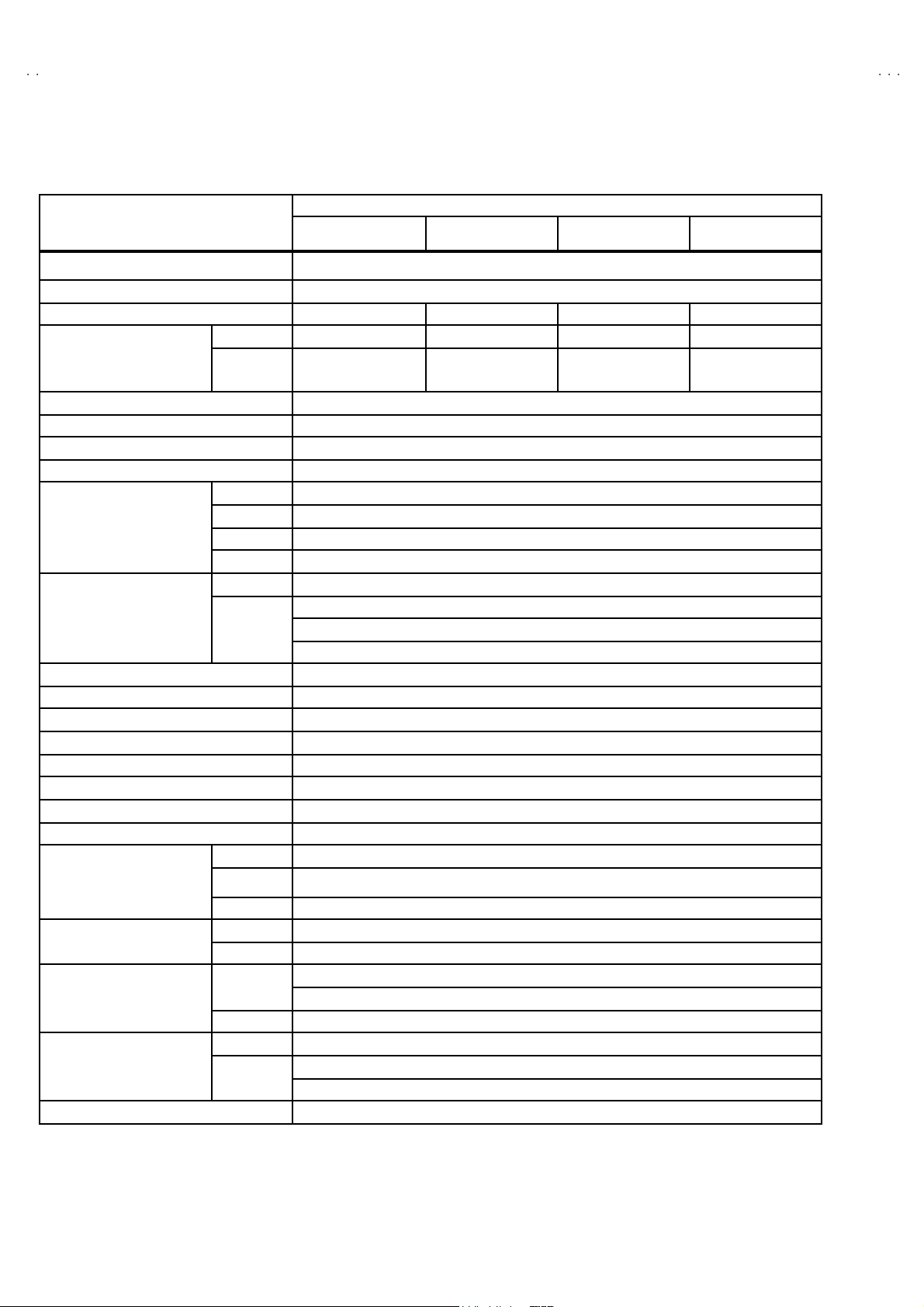
SPECIFICATIONS
Content
Item
Dimensions (W x H x D) 60cm x 45cm x 48cm
Mass 22.2 kg
TV RF System B/G B/G, D/K, K1 I/I’ B/G, L/L’
TV Mode PA L PA L / SEC A M PAL PAL / SECAM
Colour Sy stem
Teletext System Fast ext / TOP
Stere o Sy st em A2 / NICAM
Tuning System Fr equenc y Synt hes izer Tun in g S ystem
Numb er Of CH me mory pos ition 10 0 ch
Receiving Frequency
Intermediate Fr equency
Colour Sub Carrier Frequency PAL (4.43MHz), SECAM (4.43MHz), NTSC (3.58MHz/4.43MHz)
Aerial Input Termi nal 75 Oh m Un b al anc ed
Power Input AC 1 70V ~ 270V , 50H z
Power Consumpti on 95W (Max.) / 73 W (Avg.)
Pictur e Tube 21 inch measu red diag on al ly
Hi gh Vo lt ag e 27kV ( in cut-off serv ice mo de)
Speake r 57mm x160mm ellipse type x2
Au dio Output 8W+8W
Input
Output
Remote Control Unit VE-30015781 (RM-C85 ), Batte r y size :AA A/R03 x 2
Video Mode
VHF (VL) 46.25MHz ~ 168.25MHz
VHF (VH) 17 5.25MHz ~ 46 3.2 5MHz
UHF 47 1.2 5MHz ~ 86 3.25M Hz
CATV Super (S11-S20) & Hyper (S21-S41) bands receivable
VIF Carrier 38 .9 MHz
SIF Carrier
Vide o 1V(p-p), 75 Ohm
S/V ideo
Au di o (L/R)50 0 mV( rms) , H i g h Im pe dance
Vide o 1V(p-p), 75 Ohm
Au di o (L/R)50 0 mV(rms), Low I mp ed anc e
Rear Sid e
Front Side AV 3 ( Vi d eo/A udio)
Front Side
Rear Sid e
AV21 BF10 ENS AV21 BF10 EES AV 21BF10EJS AV21 BF10 EPS
PA L / N TSC 3. 58 /
NTSC4.43
32.4 MHz (6.5 MHz)
32.9 MHz (6.0 MHz)
33.4 MHz (5.5 MHz)
Y : 1V(p-p) Positive
C : 0.286V(p-p)
AV 1 ( Vi d eo/A udio/RGB)
AV 2 (Vid eo/A ud io/S-VHS)Input Terminal
Headph on e jac k (Ster e o m i ni jac k 3.5∅)
AV1 (V ideo/Audio)Output Ter minal
AV2 ( V i deo /Audio) ( Sel ecte d TV, AV1 o r AV3 )
PA L / SE C AM /
NTSC3.58 /
NTSC 4.43
PA L / NTSC3. 58 /
NTSC4.43
PA L / SE CAM /
NTSC3.58 /
NTSC 4.43
De sign & sp eci ficatio ns ar e su bje ct to change wi thou t no t ice.
2
No.51884
Page 3

A
V21BF10ENS
A
S
A
A
S
V21BF10EE
V21BF10EJS
V21BF10EP
■■■■21-pin Euro connector (SCART socket) : AV-1 / AV-2
(P-P= Peak to Peak, S-W= Sync tip to white peak, B-W= Blanking to white peak)
Pin
Signal Designation Matching Value AV-1 AV-2
No .
1 AUDIO R o ut put 50 0mVr ms( N ominal),Low im pe dance
2 AUDIO R input 500mVrms(Nominal),High impedance ○○
3 AUDIO L o utput 50 0mVr ms( N ominal),Low im pe dance
4 AUDIO G ND
5 GND (B) ○○
○
(TV OUT)
○
(TV OUT)
○○
○
(TV/LINE OUT )
○
(TV/LINE OUT )
6 AUDIO L input 500mVrms(Nominal), High impedance
B-W
7B input
FUNCTON SW
8
(SLOW SW)
9 GND (G)
10 - NC -
11 G i n put
12
- NC -
13 GND (R)
14 GND (YS) ○ NC
15 R / C input
16 Ys in put L ow : 0 – 0. 4, Hi g h : 1 - 3 V, 75 Ω○NC
17 GND(V IDEO output)
18 GND(V IDEO input) ○○
19 VID EO outpu t
20 VIDEO / Y inp ut 1V
70 0mV
Low : 0-3V, High : 8-12V, High impedance
70 0mV
R : 700mV
C : 300mV
1V
, 75Ω○
B-W
, 75Ω○
B-W
, 75Ω
P-P
, 75Ω
S-W
(Negative going sync), 75Ω
S-W
(Negative going sync), 75Ω○○
○○
NC
○
○○
○○
○
(R/C)
○○
○
(TV)
NC
NC
○
(only C)
○
(TV/LINE OUT)
21 COMMON GND
○○
[Pin assignment]
No.51884
3
Page 4

A
V21BF10ENS
A
A
A
V21BF10EES
V21BF10EJS
V21BF10EPS
SAFETY PRECAUTIONS
1. The d es ign of th is prod uct c on ta ins sp eci al har d wa re, ma ny
circuit s and components specially for saf ety purposes. For
con tinu ed pr ot ection , n o chan g es sh ou ld b e ma de to the o ri g inal
d esi gn un l ess auth oriz ed in writi n g by th e ma nu fact urer.
Replac em en t p arts m ust be ident ic al to thos e u sed in th e or i ginal
ci rcu it s. Serv ic e sh ou ld be pe rf or me d b y q ua lifie d perso nn el
on ly.
2. Alte r ati on s of the design or ci r cui try of t he prod ucts sh ould not be
made. Any design alterations or additions will void the
manufact ur er 's warrant y and will f urth er r eliev e t he ma nu factu r er
of r esp onsi b ility for per so na l injur y or p r op er ty d am ag e r esult ing
th erefr om.
3. Man y e lectr i cal an d mech ani cal parts i n the products ha v e
special safety-related characteristics. These characteristics are
oft en no t e v ident f r om v isua l i nsp ection n or ca n t he pr o tec t io n
aff or de d by th em nece ssar i l y be ob tain ed b y u sin g r ep l acement
com po ne nts ra ted f or hig he r vol tage, watt ag e, etc. R ep l acem en t
p arts whic h ha ve th ese sp eci al s afet y ch ar ac t er ist ics are
ide ntified i n the parts list of Servic e manua l. El ec tric al
components having such features are ide nti fied by shading
on t he sche mat ic s an d by (!!!! ) on the parts list in Service
manual. The us e of a sub s ti tu te rep lacem en t whi ch does n ot
h ave th e same saf ety ch ar act er ist ics as t he r eco mmen de d
replac em ent part sh own i n th e p ar ts lis t of S er vic e man ual may
cause shock, fire, or other hazards .
4. Don't shor t between the LIVE side ground and ISOLATED
(NE UTRAL) side ground or EARTH side ground when
repairing.
Some model's power circuit is partly different in the GND. The
diff er enc e of the GN D is sh own by the LI VE si de G ND, the
ISO LATED(NEUT RAL) side GND a nd EA RTH si de GND. Don' t
sh ort b etw ee n the L IVE si de GN D a nd IS OLAT E D( NEUTR AL)
si de GN D or EA R T H side GN D an d ne ver meas ur e w i th a
measu ring app ar atu s (osc illosc ope et c.) th e LIVE si d e GND an d
ISOLATED(NEUTRAL) side GND or EARTH side GND at the
same time.
If above note will not be kept, a fuse or any parts will be broken.
5. If any repair has been made to the chassis, it is recommended
th at t he B1 set ti ng s hou l d b e ch eck e d or adju ste d ( Se e
ADJUST MENT OF B1 POWE R SUPPL Y) .
6. The hi gh v olta ge app li e d t o th e pictu re tu be mu st confor m wit h
th at s p ecified in S ervi ce manual. E xcessi ve high volt ag e c a n
cau s e an i ncr e ase i n X- R ay em i ssi on , ar c ing an d possi b le
component damage, therefore operation under excessive high
voltage conditions should be kept to a minimum, or should be
preve nt ed. If s ever e arc ing occ ur s, r emove t he AC pow er
immed i ate ly an d de ter m i ne th e c a use b y visua l insp ec t io n
(inc or rect ins tal lat i on, cracke d or melte d high vo ltage har n ess,
p oor so lder i ng, et c.). To maint ai n the p roper min im u m le vel of
sof t X- R ay emi ssi on, c omp on en ts i n th e hi gh v oltag e cir c uitr y
incl ud ing t he pi ct ur e tu be must be t he e xact r ep l aceme nts or
alte rn at i ves ap pr ove d b y th e ma nuf act urer of th e c om pl et e
product.
7. Do not c hec k high volt age b y dr awing an ar c. Us e a high vol t age
meter or a hi g h v oltag e pr ob e wit h a V TVM. Discharge th e
picture tube before attempting meter connection, by connecting
a cl i p lead to th e gr ou nd f ra me and c onn ectin g th e other end of
the lead through a 10kΩ 2W resi sto r to the anod e butt on .
8. When se rvice i s requ ire d, ob ser v e th e or i gi na l lea d dress. E xtr a
prec aut ion sh ou ld b e g iven t o ass ur e corr ec t l ea d dr ess i n the
high vol tag e c ircui t a r ea. W her e a s hort ci r cuit h as oc cu rre d,
th ose co mp on ent s tha t i ndi ca te evide nce of ove r hea ting sho ul d
b e r e pl ace d. A l wa ys u se th e ma nuf act urer's r ep l acem en t
components.
9. Isol ation Check
(Safety for Electrical Shock Hazard)
Af ter re- ass emb l in g th e pr odu c t, al w ays per f orm an i sol at ion
ch ec k on the expo sed metal parts of t he c abin et ( a ntenn a
ter m inals, video /audio inpu t and ou tput t erminals , C on trol kn obs,
metal cabinet, screwheads, earphone jack, control shafts, etc.)
to be s u re th e p roduct is s af e t o ope r ate with ou t dan ger of
elect ri cal s hoc k.
(1) Dielectric Strength Test
The iso l ati on be tween the AC pr imary ci rcuit an d all metal parts
exp osed t o th e us er , p arti cular l y any e xp os ed met al p art having a
retu rn p ath to t he chass is sho uld withs tan d a vol t age of 3 000 V
AC (r.m.s.) for a period of one second.
(. . . . W it hs tan d a v o lt ag e of 1 10 0V A C (r.m. s.) t o an applianc e
rate d up to 12 0V , an d 3 00 0V AC ( r .m. s.) to an ap pl ian ce r at ed
200V or more, for a period of one second.)
This meth od of test requi res a t est equ ipment n ot g enerally found
in t he servic e trad e.
(2) Leakage Current Check
Plug th e A C line c ord d irect ly into th e AC ou tlet ( d o not use a line
isol ati o n tr ansf or m er du r in g thi s ch eck.). Usi n g a " Lea kage
Curr ent T este r", me asur e th e lea kag e cu rre nt f rom each exp osed
metal p art of the cabinet, p art icu larly any expos ed me tal p ar t
h avi ng a re tur n path to the c h assis , t o a kn own go od ea rt h
ground (water pip e, e tc.) . An y l eaka ge curren t m ust n ot e xceed
0.5mA AC (r.m.s.).
Howev e r, i n tr op ic al area , th is must no t exce ed 0.2 mA AC
(r.m.s.).
"""" Alternate Che ck M et hod
Plug th e A C line c ord d irect ly into th e AC ou tlet ( d o not use a line
isol ati o n tr an s for m er dur ing t hi s che c k.). U se an AC vo lt me ter
h avi ng 1 00 0 ohms pe r volt or mor e s ens itivi ty in th e fo ll owing
manner. Con nec t a 1 50 0Ω 10W res ist or para lle le d b y a 0 .1 5µF
AC-type c apa cit or bet ween an expo sed met al pa rt a nd a known
g ood e ar th gro un d (water pipe , etc.). M eas ure th e A C volt ag e
acr oss th e res ist or w ith th e AC vo ltm eter . Move th e r esis tor
con nec ti on to each exp ose d metal part, part ic ularly a ny exp os ed
metal p art havin g a retu rn pat h to t he ch as sis , an d m easu re th e
AC vol tag e ac ro ss the res ist or . No w, re vers e th e pl u g i n th e AC
ou tl et and re pe at eac h mea s ur emen t. Any volt ag e me asured
must no t e xceed 0 .75V AC (r.m. s.). This c orre spo nds to 0.5mA
AC (r.m.s.).
Howeve r, in tropica l are a, this must n ot exceed 0.3V AC ( r.m.s.).
This corresponds to 0.2mA AC (r.m.s.).
AC VOLT METER
(HAVING 1000 Ω /V,
OR MOR E SENSIT IVITY)
0.15μF AC -T YPE
PLACE THIS PROBE
1500 Ω 10W
GOOD EARTH GROUND
ON E A C H EX PO SE D
ME T AL PA RT
4
No.51884
Page 5
A
A
S
A
A
S
FEATURES
V21BF10ENS
V21BF10EE
V21BF10EJS
V21BF10EP
1. It is a remote controlled color tele vision.
2. 100 programs fr om VH F , UHF b an ds or cable cha nn el s can be
pres et.
3. It c an tun e c able cha nn el s.
4. Cont ro llin g the TV is ver y easy by its m en u driven s yst em .
5. It has two Eurocon n ector s ock ets fo r exte rnal device (such as
vi de o r eco rder, vid eo ga mes , a udio set, e tc.)
6. Fr ont AV Inp ut av aila ble.
7. St ereo s ound s ystem s (German + Nic am) ar e a vail ab l e.
8. Full fu nction Tele text (Fast ext, Topte xt).
9. It i s possible to connec t head phon e.
10. Direct channel access.
11 . APS (Aut om at ic Programming System).
12 . All programs ca n b e nam ed .
13 . Forwar d o r backw ard au to ma tic tu ni ng .
14 . Au tomat ic sou nd mu te wh en no tran smission.
15 . 5 mi nu tes aft er the br o adc asting (cl osedown), the T V s witch es
itsel f automatica lly t o st and -by mod e.
MAIN DIFFERENCE LIST
MODEL No.
Parts Name
MAIN PW B VE-2 00738 51 VE -2 00 738 61 VE -2 00 73856 VE -2 00 73866
AV21BF10ENS AV21BF10EES AV21BF10EJS AV21BF10EPS
MULTISOUND PWB VE-20078991 VE-20079020
INST B OOK VE -5 00 246 64 VE -5 00 24666
TV RF system B/G B/G, D/K, K1 I/I’ B/G , L /L’
Colour s ystem
(TV MODE)
PA L PAL / SECAM PAL PAL / SECAM
VE -5 00246 70 VE -500 24668
No.51884
5
Page 6

A
V21BF10ENS
A
A
A
V21BF10EES
V21BF10EJS
V21BF10EPS
SPECIFIC SERVICE INSTRUCTIONS
DISASSEMBLY PROCEDURE
REMOVING THE REAR COVER
1. Remove th e 6 screws marked A.
2. Withdraw t he R EAR COV ER t owar d you.
REMOVING THE FRONT AV + HEADPHONE JACK
PWB
" Take out t he rear co ver.
1. Remove th e 2 s c re ws ma r ked B, an d remove th e FRONT A V +
HEAD PHONE J ACK P WB.
A
REMOVING THE SPEAKER
" T ake ou t t he rear co ver.
1. R em ove the 4 screws marke d C as sh own in the fig ure.
2. R em ove th e sp eake r.
3. Rem ov e th e othe r hand spe ak er same step.
REAR COVER
MAIN PWB
PI CTUR E TUB E
C
B
FRON T CABI NET
FRON T CABI NET
SPEAKER (LEFT & RIGHT)
FRON T AV +
HEADPHONE JACK PWB
6
No.51884
Page 7

A
A
S
A
A
S
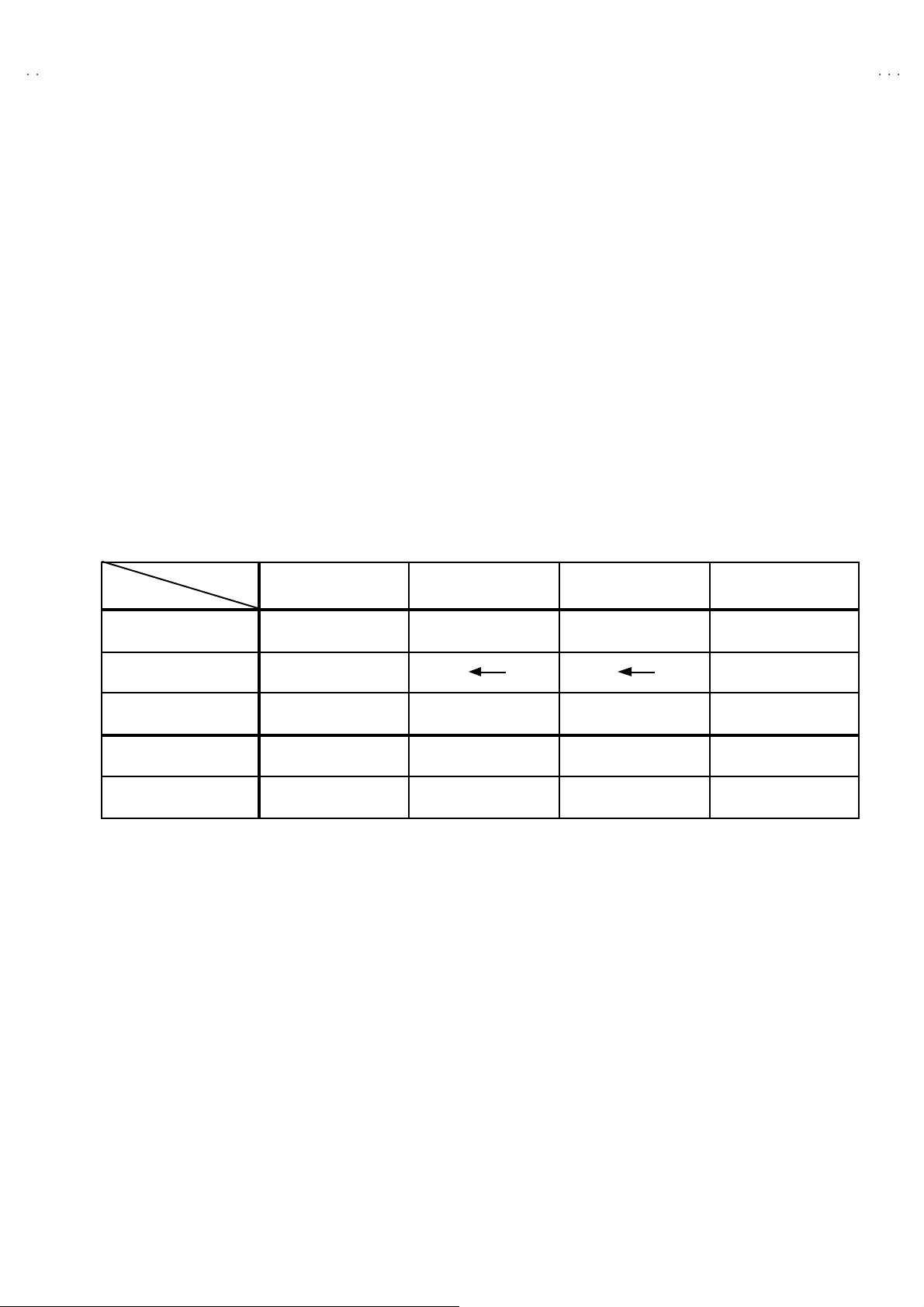
SETTING OF THE LAST MEMORY FOR SHIPMENT
■■■■ USER SETTING VALUES
Setting Item Setting Value Setting Item Setting Value
SOUND MENU FEATURE MENU
BA SS CEN TER SLEEP TIMER OFF
TR EBL E
↑
CHILD LO CK OFF
V21BF10ENS
V21BF10EE
V21BF10EJS
V21BF10EP
BALANCE
EFFECT OFF
PICTURE MENU INSTALL TV CONFIG. MENU
BRIGHT NES S LANGUAGE ENGL ISH
COLOUR COUNT RY ?
CONTRAST AV-2 OUTPUT TV
SHAR PNES S
HUE (only NTSC)
PICTURE MODE AUTO
Thes e ad j ust a re aut om atic a lly
restor ed wh en A PS bi t in S ervic e
menu is set .
The p ro ced ure for sel l ing AP S
bit is described bellow.
↑
■ SETTING APS BIT IN SERVICE MENU
1) En ter s ervi ce menu in TV mode by pressing “INFO” and “ M UTI NG ” keys si mu lt an eou sly . Se rvice Men u will app ear.
2) Se le ct OP TION S by press ing Up /D ow n keys on r em o te c ont ro l un it .
3) Enter OP TIONS by press in g Left /Right ke ys on rem ote control unit.
4) Select OP TION 8 by pressing Up/Down ke ys on remote control unit.
5) Selecte d bit in one OPTI ON is shown by bli nking ch aracter. Se lect B 2 b y press ing L eft /Rig ht keys on remote con trol unit .
DO NOT CHANGE ANY OT HER BIT.
6) Press digit key “1” to set APS bit .
7) Pr ess “ ST A NDARD” key on rem ot e contr ol unit t o exit ser vic e mo de .
No.51884
7
Page 8

A
V21BF10ENS
A
A
A
V21BF10EES
V21BF10EJS
V21BF10EPS
REPLACEMENT OF CHIP COMPONENT
! CAUTIONS
1. Avoid heating for more than 3 seconds.
2. Do n ot rub t he elect rodes an d t he r esis t p ar ts of the patt ern.
3. When r emovi ng a c hip part, mel t th e s older ad equate ly.
4. Do n ot reuse a chip part after removi ng it .
! SOLDERING IRON
1. Us e a hi g h i ns ulati o n solder ing iron with a t hi n po in ted end of it.
2. A 3 0 w s older ing iron is rec omm end ed for easil y remov ing p ar ts .
!
REPLACEMENT STEPS
1. How to remove Chip parts
# Resi st ors, ca pacitors, et c .
(1) As sho wn in th e fi gur e, pus h the pa rt with tweezer s a nd
alte rn at el y melt th e s older at each en d.
2. How to install Chip parts
# R esi st o rs, capacitors , et c .
(1) Apply solder to the patt ern as indicate d in the fig ure.
(2) Sh if t w i th tweezers an d rem o ve th e chip part.
#
Transist ors, diodes , varia bl e resist or s, etc.
(1) Ap ply e xt ra solder to ea ch le ad.
SOLDE R
(2) As sho wn in th e fi gur e, pus h the pa rt with tweezer s a nd
alte rn at el y melt the sold er at e ach le ad . Shi ft and remove
the chip p art.
SOLDE R
(2) Grasp th e ch ip p art with t w eez ers and p lac e it on th e
sol d er . Th en h eat and me lt th e s o ld er at b oth ends of the
chip part.
#
Transist ors, diodes , varia bl e resist or s, etc.
(1) Apply solder to the patt ern as indicate d in the fig ure.
(2) Grasp th e ch ip p art with t w eez ers and p lac e it on th e
solder.
(3) First s older lead A as indicated i n the fi gure.
A
B
C
(4) The n solder l e ads B and C .
A
B
Note : After removing the part, remove remaining solder from
the p atte rn.
8
No. 51884
C
Page 9

A
A
S
A
A
S
SERVICE ADJUSTMENTS
/C
ADJUSTMENT PREPARATION
1. You ca n ma ke t h e nece ssa ry adjust ments f or this u nit wit h
either the Remote Control Unit or With the adjustment tools
and parts as given below.
2. Adjustment with the Remote Control Unit is made on the
basis of the initial setting values, however, the new setting
values which set the screen to its optimum condition may
differ f rom the initia l sett ings.
3. M ake sur e that AC p ower is turned o n c orrec tly.
4. T urn on th e pow er for s et an d test eq uip ment bef or e use , and
start t he adj ustmen t p r oced ures aft er waiting at leas t 30 m in ut es.
5. U nl ess o the rwise s pec if i ed, pr ep ar e t he mo st su itab le recep tion
or inp ut si gn al for adjust ment.
6. N ever tou ch any ad j ustm en t p arts wh ic h ar e n ot sp eci fi ed in t he
list for t his adjustment - variable resistors, transformers,
condensers, etc.
7. Pr es etti ng b efore adj ustm en t.
Unles s ot her wis e spec if i ed i n t he a dj ustm e nt i nstr uct ions, p r eset
th e f ollo wing f uncti ons with th e r e mo te c ont ro l un it :
VIDEO STAT US STA NDARD
TINT/COLOR
PICTURE/BRIGHT
DETAIL
V21BF10ENS
V21BF10EE
V21BF10EJS
V21BF10EP
CENTER
ADJUSTMENT EQUIPMENT
1. DC voltmeter (or digital voltmeter)
2. Si gn al g en er at or (P att ern g ener ator) [PAL/SECAM/NTSC]
3. Remote control unit
MAIN PARTS LOCATIONS
REMO CON
RECEIVER
LE D
IC50 2
ME MO RY IC
ME NU
IC50 1
MI CO M
(+)
(+) (-)
(+)(+)
PROG
h.
(-)
(-)(-)
(+)
(+) (-)
(+)(+)
VOL
(-)
(-)(-)
MAIN POW ER SW
FBT
MULTI SOUND PWB
SCAR T
jack
TUNER AV-1 AV -2
SCAR T
jack
No. 51884
(Ind ic ated [1 50 /11 5V]
B1
on th e bott om s ide)
UPPER : FOCUS VR
LOWER : SCR EEN VR
9
Page 10

A
V21BF10ENS
A
A
A
SERVICE MENU SCREEN
ADJUS
V21BF10EES
V21BF10EJS
V21BF10EPS
BASIC OPERATION SERVICE MENU
■■■■ HOW TO ENT ER THE SERVICE MODE
1) Press the INFORMATI ON key and MUTING key of REMOTE
CONTROL UNIT, simultaneously.
■■■■ SELECTION OF ADJUSTMENT ITEMS
1) Press the UP ( ) or DOWN ( ) key and select
th e se rvi ce menu item .
2) Press the LEFT ( ) or RIGHT ( ) key and
enter ADJUSTMENT SCREEN.
3) Se le ct t he AD JUST N o., use UP ( ) / DOWN ( )
key of r em ot e c ontr o l un it.
4) T o chan ge th e se lected par amet er, us e LEFT ( )
an d RIGHT ( ) key.
SE RVICE
ME NU ITEM
PA RAMET ER
VA LUE
SERVICE
ADJUST…..
OPT IO NS…..
ADJUST *** ******
** *
OU T UP
T No.
PA RAMET ER
■ HOW TO EXIT SERVICE MODE
1) Press the STANDARD Key on REMOTE CONTROL UNIT.
■■■■ ADJUS TMENT SERVICE MENU
ADJUSTMENT ITEM
AGC 03 AGC
IF-PLL NEGATIVE 04 IF-PLL Negative
IF-PLL PO SITIV E 05 IF -PLL P ositiv e
4 : 3 HORIZONTAL SHIFT
VERTICA L SLOPE
VERTICA L AMPLITU DE
ADJUST
No .
00 White Point RED
01 White Point GREENWHIT E BA LANCE
02 White Point BLUE
06 Y-Delay PAL
07 Y-Delay SECAMLUMINANCE DELAY
08 Y-Delay NTSC
12 4 : 3 PICT U RE MO DE
23 16 : 9 PICTURE MODE
13 4 : 3 PICT U RE MO DE
24 16 : 9 PICTURE MODE
14 4 : 3 PICT U RE MO DE
25 16 : 9 PICTURE MODE
DISCRIPTION
MUTING key
UP / DOWN
/
(
) key
ADJUSTMENT SCREEN
REMOTE CONTROL UNI T key NAME
STANDARD key
LEFT / RIGHT
/
(
) key
10
INFORMATION
key
No. 51884
Page 11

A
A
S
A
A
S
ADJUSTMENTS
Item
SCREEN
VOLTAGE
adjust ment
Measuring
instrume nt
Signal
generator
Remote
control
unit
SERVICE
ADJUST…..
OPT IO NS…..
Test point Ad justment part Description
SE RVICE M ENU
SCREEN VR
[FBT]
OPTI ON 02
V21BF10ENS
V21BF10EE
V21BF10EJS
V21BF10EP
1. Receive a PA L co lour b ar.
2. En ter th e opt ion s etti n gs in th e SE RV ICE MEN U .
3. Press the UP / DOW N ( ▲/ ▼) key, and Enter Option 02.
4. To c h an ge bit 6, c om e o n t o it b y usi n g L / R (
make it “1 ” b y pres si n g “1” whit e b it 2 is b li nki ng .
5. Ob serve t he th in horizon tal blu e- white line in t he m i dd l e o f the
screen , and ad ju st t he SCR EEN V R of t he FBT , u ntil th e line is
in its thinnest visib le thickness.
6. The n m ake Op tion 02 b it 6 “ 0” , b y p re ss ing “ 0” on the re mo te
control unit, although you do not see any picture.
/
) key and
FOCUS
adjust ment
SELECT OP TION menu
FBT
FOCOUS
SCR EEN
Signal
generator
FOCUS VR
[FBT]
1. Receive a PA L cir cl e patt ern.
2. Ad just th e FOCUS VR of t he FBT , un til y ou get th e o pti m um
foc us, the sharp est picture.
B1
VOLTAGE
che ck
DC
voltmeter
Marked
[150/1 15V]
on the
MAIN PWB
No. 51884
1. Check whet her the vo ltag e at th e p oint n am ed an d s ilk
screen ed as “150 / 11 5V” o n the MAIN PWB is 150 V DC.
11
Page 12

A
V21BF10ENS
A
A
A
)
)
)
V21BF10EES
V21BF10EJS
V21BF10EPS
Item
WHITE
BALANCE
adjust ment
AG C
adjust mentDCvoltmeter
Measuring
instrume nts
Signal
generator
Test point Adjustment part Descrip t io n
ADJUST 00
(White point
- RED
ADJUST 01
(White point
- GREEN
ADJUST 02
(White point
- BLUE
ADJUST 03 1. R eceive a any bro adc ast.
[LOW LIGHT]
1. Rec eive a wh ol e bl ac k signa l.
2. Adjus t th e <Ad just 00>, <Adju st 01 >, <A dj ust 02> , i n th e
SE RV ICE M EN U so that th e ent ire s creen do n ot s h i ne bl ack .
[HIG H LIGHT]
1. Rec eive a wh i te a nd bl ac k si gn al (col ou r off ).
2. Adjus t th e <Ad just 00>, <Adju st 01 >, <A dj ust 02> , i n th e
SE RV ICE M EN U s o th at th e whiten ess in t he sc re en bec om e
sharp.
2. Select < A DJ US T 03 > from S ERVICE MENU
3. C on nect a DC vo lt me ter to p in 1 of the tu ne r. Ch an ge the
AGC p ar am ete r unt il yo u s ee 3.7 0V DC on vol tm et er dis pla y.
IF-PLL
NE GA T IVE
adjus tment
IF-PLL
POS ITIVE
adjus tment
ADJUST 04 1. Select < A DJ US T 04 > from S ERVICE MENU.
2. Adjustm en t value is s et t o 8 0 as a def ault value.
ADJUST 05 1. Select < A DJ US T 05 > from S ERVICE MENU.
2. Adjustm en t value is s et t o 8 0 as a def ault value.
12
No. 51884
Page 13

A
V21BF10ENS
A
S
A
A
S
V21BF10EE
V21BF10EJS
V21BF10EP
Item
LUMINANCE
DE L AY
adjust ment
Measuring
instrume nts
Signal
generator
Test point Ad justment part Description
Adjust 06 [ Y- Delay P AL ]
1. Receive a PA L co lour bar si gn al .
2. Select <Adjust 06> from SERVICE ME NU.
3. Adjust Y-D el ay PAL till the colour transien ts on the colour
b ar of th e pa tter n beco me a s sh arper a nd col ou rs b etwe en
tr ansi e nts do no t mi x wit h each oth er as pos si bl e.
Note : If th e S AW fi lt er is one of th e G1 965M , J 1 95 1M , K295 8M,
K2 962 M, G395 7M, K 6256K , K6 259K or M1 96 3M, th ere i s
con stan t g roup de lay d is tortion , so for an equal d el ay of
th e l um ina nce and chromin ance si gn al th e d ela y mus t b e
set at a value of 160nS. This means the adjustment must
be set to the maximum value.
Adjust 07 [ Y- Delay SECAM ]
1. Receive a SE CAM colour bar si gn al .
2. Select <Adjust 07> from SERVICE ME NU.
3. Adjust Y-Del ay SECAM till t he col o ur tr an s ients on th e
col o ur b ar of th e p atter n b ec o me a s sh ar per an d c ol ou rs
b etw een t ransien ts d o n ot mix wi th eac h o the r as p oss ible .
Note : If t he SAW filter is one of th e G1 965 M, K 29 58M ,
K2 962 M, G395 7M, K62 56 K or K 62 59K , th er e is c on stan t
group d elay d ist or ti on , s o for an e qu al de lay of t he
lumi nan ce and chr omin anc e signal th e d el a y must b e
set at a valu e of 160 nS. This m ea ns th e adj u stment m ust
be set to the maximum value.
Adjust 08 [ Y- Delay NTSC ]
1. Receive a NT SC co lour b ar si gn al.
2. Select <Adjust 08> from SERVICE ME NU.
3. Adjust Y- Del ay NT SC t ill the col ou r tr ansie nts on th e co lour
b ar of th e pa tter n beco me a s sh arper a nd col ou rs b etwe en
tr ansi e nts do no t mi x wit h each oth er as pos si bl e.
Note : If th e SAW filt er is M1 963M , there is constant group delay
disto rt ion, so f or a n e qu al de l ay of th e l u min anc e an d
chr o mi n ance si gn al th e d elay mu st b e s et a t a val u e of
16 0ns . This me an s th e ad ju stment m ust b e set t o the
maximum value.
No. 51884
13
Page 14

A
V21BF10ENS
A
A
A
V21BF10EES
V21BF10EJS
V21BF10EPS
Item
4 : 3
HORIZONTAL
SHIFT
Ad j ust men t
VERTICAL
SLO PE
Ad j ust men t
Measuring
instrume nts
Signal
generator
Signal
generator
Test point Ad justment part Description
Ad ju st 12 ( 4 : 3 )
Ad ju st 23 ( 16 : 9 )
Ad ju st 13 ( 4 : 3 )
Ad ju st 24 ( 16 : 9 )
1. Receive a RED t est pa ttern .
2. Se t < 4 : 3 as p ec t m od e >.
3. Select < ADJUST 12 > f rom S ERVICE MENU.
4. Change horizontal shift till the picture is horizontally
cen tered. C h eck w het her t his ad j ustmen t i s cor r ect after
com pl e ti ng Ser vice Mo de Ad ju stm en t.
5. Se t < 16 : 9 a sp e ct mo de >.
6. Ad justs with the step wh ic h i s t he sa me ab ove fro m 3 t o 4
ab out the 1 6 : 9 asp ect m od e, too.
1. Recei ve a cross-hatch si gna l .
2. Se t < 4 : 3 as p ec t m od e >.
3. Select < ADJUST 13 > f rom S ERVICE MENU.
4. Cha nge ve rt ic al sl op e t ill the si ze of squ ares on b oth t he
up per a nd l o we r part of tes t p att er n bec ome e qu al t o th e
squ ar es layi n g on the ver ti cal ce nter of th e te st pa tte rn.
Check and readjust VERTICAL SLOPE item if the
ad justm en t b ecomes i mpro per af ter s o me ot her geo metr ic
adjustments are done.
5. Se t < 16 : 9 a sp e ct mo de >.
6. Ad justs with the step wh ic h i s t he sa me ab ove fro m 3 t o 4
ab out the 1 6 : 9 asp ect m od e, too.
VERTICAL
AMPLIT UDE
Ad j ust men t
Signal
generator
Ad ju st 14 ( 4 : 3 )
Ad ju st 25 ( 16 : 9 )
1. Receive a PA L tes t patt ern sign al.
2. Se t < 4 : 3 as p ec t m od e >.
3. Select < ADJUST 14 > f rom S ERVICE MENU.
4. Cha nge ver ti cal s lo pe till ho rizo ntal bl ack l i nes o n bo th th e
up per an d lower par t of th e test p att ern bec om e v ery c lose
to th e u ppe r and lowe r horizonta l sid es of pict ur e tub e an d
n early ab out t o d is app ea r. Chec k and read just V ERTICAL
AMPL IT UDE item if t he adju stment be comes improper af ter
som e other geom et ric adjus tments are d on e.
5. Se t < 16 : 9 a sp e ct mo de >.
6. Ad justs with the step wh ic h i s t he sa me ab ove fro m 3 t o 4
ab out the 1 6 : 9 asp ect m od e, too.
14
No. 51884
Page 15

A
V21BF10ENS
A
S
A
A
S
V21BF10EE
V21BF10EJS
V21BF10EP
Item
S-CORRECTION
Ad j ust men t
VERTICAL
SHIFT
Ad j ust men t
Measuring
instrume nt
Signal
generator
Signal
generator
Test point Ad justment part Description
Ad ju st 15 ( 4 : 3 )
Ad ju st 26 ( 16 : 9 )
Ad ju st 16 ( 4 : 3 )
Ad ju st 27 ( 16 : 9 )
1. Receive a PAL circ le p att ern signal.
2. Se t < 4 : 3 as p ec t m od e >.
3. Select < ADJUST 15 > f rom S ERVICE MENU.
4. Change S-correction till the middle part of the circle is round
as possi b le .
5. Se t < 16 : 9 a sp e ct mo de >.
6. Adjusts with the step which is the same above from 3 to 4
ab out the 1 6 : 9 asp ect m od e, too.
1. Receive a PA L tes t patt ern si gn al ( o r the sym me tr ic al sign al
in the top and the bottom and on either side to find ).
2. Se t < 4 : 3 as p ec t m od e >.
3. Select < ADJUST 15 > f rom S ERVICE MENU.
4. Cha nge Ve rtic al Sh if t til l t he tes t pattern is vertical ly cent er ed ,
i.e. hor i zon tal line at the c e nte r patt er n i s in equal dist an ce
b oth to upp er and lower side of t he pi ct ur e tub e. Ch eck an d
readjust V ertical S hi ft ite m if t he adj u s tm ent bec om es
impr oper aft er s om e oth er g eom et ric a djust ments are d on e.
5. Se t < 16 : 9 a sp e ct mo de >.
6. Ad justs with the s te p w hi ch is the s a me ab ov e fr om 3 to 4
ab out the 1 6 : 9 asp ect m od e, too.
No. 51884
15
Page 16

A
V21BF10ENS
A
A
A
V21BF10EES
V21BF10EJS
V21BF10EPS
[MEMO]
16
No. 51884
 Loading...