

Page 1
A
SER VICE MANUAL
COLOUR TELEVISION
AV-14F702
V-14F702
CONTENTS
SPECIFICATIONS
!
★
OPERATING INSTRUCTIONS (APPENDED)
SAFETY PRECAUTIONS
!
SPECIFIC SERVICE INSTRUCTIONS
!
SERVICE ADJUSTMENTS
!
GUIDE FOR REP AIRIN G
!
★
STANDARD CIRCUIT DIAGRAM (APPENDED)
PARTS LIST
!
・・・・・・・・・・・・・・・・・・・・・・・・・・・・・・・・
・・・・・・・・・・・・・・・・・・・・・・・・・・・・・・・・・・・・・・・・・・・・・・・・・・・・・・・・・・・・・
・・・・・・・・・・・・・・・・・・・・・・・・・・・・・・・・・・・・・・・・・・・・・・・・・・・・・・・・・・・・・・・・
・・・・・・・・・・・・・・・・・・・・・・・・・・・・・・・・
・・・・・・・・・・・・・・・・・・・・・・・・・・・・・・・・・・・・・・・・・・・・・・・・・・・・・・・
・・・・・・・・・・・・・・・・・・・・・・・・・・・・・・・・・・・・・・・・・・・・・・・・・・・・・・・・・・・・・・・・
・・・・・・・・・・・・・・・・・・・・・・・・・・・・・・・・
・・・・・・・・・・・・・・・・・・・・・・・・・・・・・・・・・・・・・・・・・・・・・
・・・・・・・・・・・・・・・・・・・・・・・・・・・・・・・・・・・・・・・・・・・・・・・・・・・・・・・・・・・・・・・・
・・・・・・・・・・・・・・・・・・・・・・・・・・・・・・・・
・・・・・・・・・・・・・・・・・・・・・・・・・・・・・・・・・・・・・・・・・・・・・・・・・・・・・・
・・・・・・・・・・・・・・・・・・・・・・・・・・・・・・・・・・・・・・・・・・・・・・・・・・・・・・・・・・・・・・・・
・・・・・・・・・・・・・・・・・・・・・・・・・・・・・・・・
・・・・・・・・・・・・・・・・・・・・・・・・・・・・・・・・・・・・・・・・・・・・・・・・・・・・・・・
・・・・・・・・・・・・・・・・・・・・・・・・・・・・・・・・・・・・・・・・・・・・・・・・・・・・・・・・・・・・・・・・
・・・・・・・・・・・・・・・・・・・・・・・・・・・・・・・・
・・・・・・・・・・・・・・・・・・・・・・・・・・・・・・・・・・・・・・・・・・・・・・・・・・・・・・・・・・・・・・・・
・・・・・・・・・・・・・・・・・・・・・・・・・・・・・・・・・・・・・・・・・・・・・・・・・・・・・・・・・・・・・・・・
COPYRIGHT © 2001 VICTOR COMPANY OF JAPAN, LTD.
・・・・・・・・・・・・・・・・・・・・・・・・・・・・・
・・・・・・・・・・・・・・・・・・・・・・・・・・・・・・・・・・・・・・・・・・・・・・・・・・・・・・・・・・
・・・・・・・・・・・・・・・・・・・・・・・
・・・・・・・・・・・・・・・・・・・・・・・・・・・・・・・・・・・・・・・・・・・・・・
・・・・・・・・・・・・・
・・・・・・・・・・・・・・・・・・・・・・・・・・
・・・・・・・・・・・・・・・・・・・・・・
・・・・・・・・・・・・・・・・・・・・・・・・・・・・・・・・・・・・・・・・・・・・
・・・・・・・・・・・・・・・・・・・・・・・
・・・・・・・・・・・・・・・・・・・・・・・・・・・・・・・・・・・・・・・・・・・・・・
・・・・・・・・・・・・・・・・・・・・・・・・・・・・・・・・・・・・
・・・・・・・・・・・・・・・・・・・・・・・・・・・・・・・・・・・・・・・・・・・・・・・・・・・・・・・・・・・・・・・・
2
3
4
8
13
21
No. 51912
Nov. 2001
Page 2
AV-14F702
SPECIFICATIONS
Items Contents
Dimensions (W
Mass
TV System and Color system
TV RF System
Color System
TV Receiving Channels and Frequency
VHF
UHF
CATV
TV/CATV Total Channel
Intermediate Frequency
Video IF Carrier
Sound IF Carrier
Color Sub Carrier
Power Input
Power Consumption
Picture Tube
Speaker
Audio Power Output
Input (1 / 2 /3)
Component Input
Antenna te rminal
Remote Control Unit
××××H××××
D)
43.2cm×34.45cm×39.35cm
26.4Ibs
CCIR(M)
NTSC
2-13
14-69
01-97 (5A)-(A-3)
98-99 (A-2)-(A-1)
14-22 (A)-(I)
23-36 (J)-(W)
37-65 (AA)-(FFF)
66-125 (GGG)-(125)
180 Channels
45.75 MHz
41.25 MHz (4.5MHz)
3.58 MHz
120V AC, 60Hz
80W
14”
1-3/5" x 2-4/5", 8 ohm x 2
2.5 W + 2.5 W
Video : 1Vp-p 75ohm (RCA pin jack)
Audio : –8dB, 47kohm (RCA pin jack)
S-Video Y : 1.0Vp-p, 75 ohm
C : 0.3Vp-p, 75 ohm
Y: 1.0Vp-p, 75 ohm
PB: 0.7Vp-p, 75 ohm
PR: 0.7Vp-p, 75 ohm
75Ω (VHF/UHF) Terminal, F-Type Connector
RM-C309G
Design & specification are subject to c hange without not ic e.
2
No.51912
Page 3
SAFETY PRECAUTIONS
SERVICING NOTICES ON CHECKING
As for the places which need special attentions,
they are indicated with the labels or seals on the
cabinet, chassis and parts. Make sure to keep the
indications and notices in the operation manual.
2. AVOID AN ELECTRIC SHOCK
There is a high voltage part inside. Avoid an
electric shock while the electric current is
flowing.
3. USE THE DESIGNATED PARTS
The parts in this equipment have the specific
characters of incombustibility and withstand
voltage for safety. Therefore, the part which is
replaced should be used the part which has
the same character.
Especially as to the important parts for safety
which is indicated in the circuit diagram or the
table of parts as a mark, the designated
parts must be used.
4. PUT PARTS AND WIRES IN THE
ORIGINAL POSITION AFTER
ASSEMBLING OR WIRING
There are parts which use the insulation
material such as a tube or tape for safety, or
which are assembled in the condition that
these do not contact with the printed board.
The inside wiring is designed not to get closer
to the pyrogenic parts and high voltage parts.
Therefore, put these parts in the original
positions.
5. TAKE CARE TO DEAL WITH THE
CATHODE-RAY TUBE
In the condition that an explosion-proof cathoderay tube is set in this equipment, safety is
secured against implosion. However, when
removing it or serving from backward, it is
dangerous to give a shock. Take enough care to
deal with it.
6. AVOID AN X-RAY1. KEEP THE NOTICES
Safety is secured against an X-ray by considering about the cathode-ray tube and the high
voltage peripheral circuit, etc.
Therefore, when repairing the high voltage peripheral circuit, use the designated parts and
make sure not modify the circuit.
Repairing except indicates causes rising of high
voltage, and it emits an X-ray from the cathoderay tube.
PERFORM A SAFETY CHECK AFTER
7.
SERVICING
Confirm that the screws, parts and wiring which
were removed in order to service are put in the
original positions, or whether there are the
portions which are deteriorated around the
serviced places serviced or not. Check the
insulation between the antenna terminal or
external metal and the AC cord plug blades.
And be sure the safety of that.
(INSULATION CHECK PROCEDURE)
1.
Unplug the plug from the AC outlet.
2.
Remove the antenna terminal on TV and turn
on the TV.
3.
Insulation resistance between the cord plug
terminals and the eternal exposure metal
[Note 2] should be more than 1M ohm by
using the 500V insulation resistance meter
[Note 1].
4.
If the insulation resistance is less than 1M
ohm, the inspection repair should be
required.
[Note 1]
If you have not the 500V insulation
resistance meter, use a Tester.
[Note 2]
External exposure metal: Antenna terminal
Earphone jack
AV-14F702
HOW TO ORDER PARTS
Please include the following informations when you order parts. (Particularly the VERSION LETTER.)
1. MODEL NUMBER and VERSION LETTER
The MODEL NUMBER can be found on the back of each product and the VERSION LETTER can be
found at the end of the SERIAL NUMBER.
2. PART NO. and DESCRIPTION
You can find it in your SERVICE MANUAL.
IMPORTANT
Inferior silicon grease can damage IC's and transistors.
When replacing an IC's or transistors, use only specified silicon grease (YG6260M).
Remove all old silicon before applying new silicon.
Licensed by BBE Sound, Inc. under USP4638258 and 4482866.
BBE and BBE symbol are registered trademarks of BBE
Sound, Inc.
No.51912 3
Page 4
AV-14F702
SPECIFIC SERVICE INSTRUCTIONS
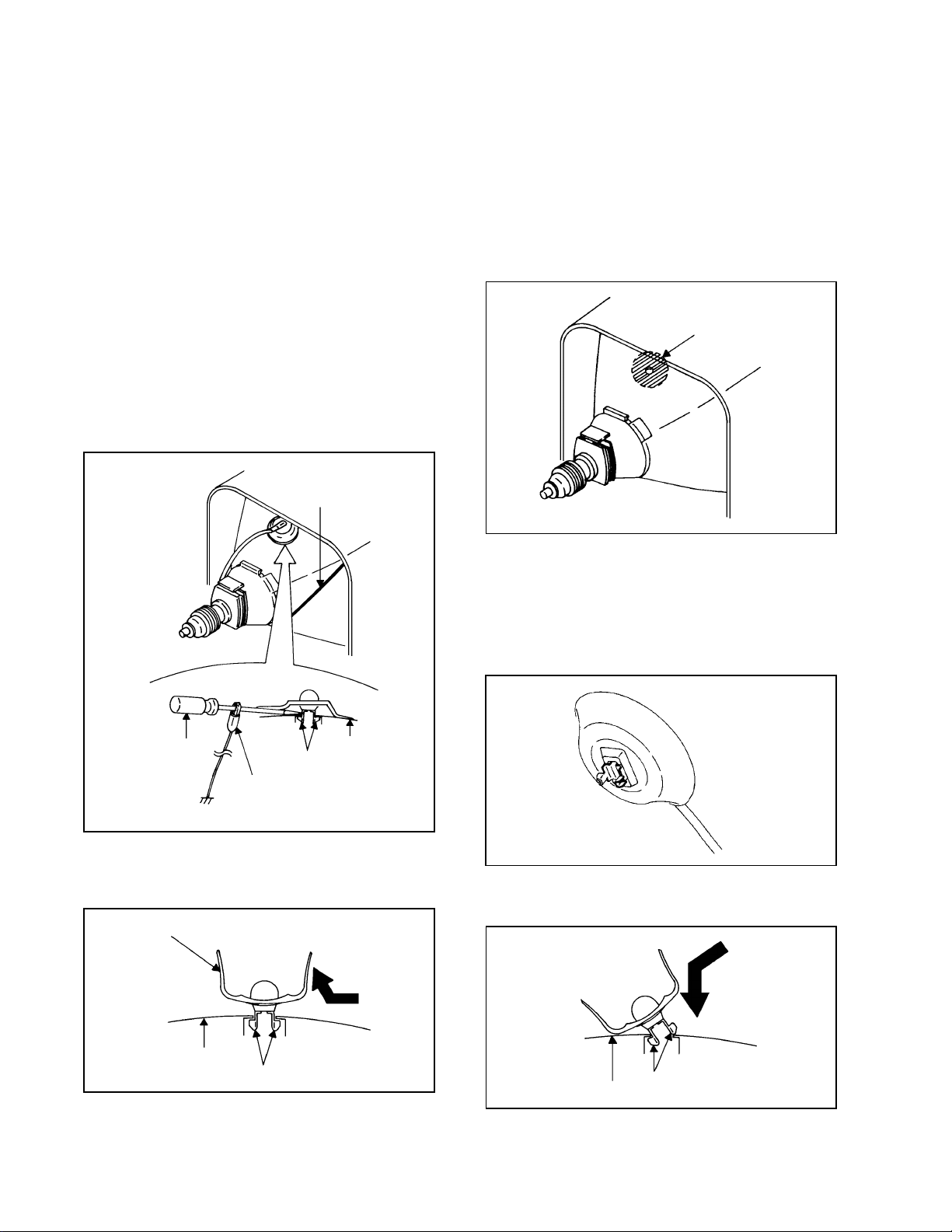
DISASSEMBLY INSTRUCTIONS
1. REMOVAL OF ANODE CAP
Read the following NOTED items before starting work.
*
After turning the power off there might still be a potential
voltage that is very dangerous. When removing the
Anode Cap, make sure to discharge the Anode Cap's
potential voltage.
*
Do not use pliers to loosen or tighten the Anode Cap
terminal, this may cause the spring to be damaged.
REMOVAL
1. Follow the steps as follows to discharge the Anode Cap.
(Refer to Fig. 1-1.)
Connect one end of an Alligator Clip to the metal part of a
flat-blade screwdriver and the other end to ground.
While holding the plastic part of the insulated Screwdriver,
touch the support of the Anode with the tip of the
Screwdriver.
A cracking noise will be heard as the voltage is discharged.
GND on the CRT
3. After one side is removed, pull in the opposite direction to
remove the other.
NOTE
Take care not to damage the Rubber Cap.
INSTALLATION
1. Clean the spot where the cap was located with a small
amount of alcohol. (Refer to Fig. 1-3.)
Location of Anode Cap
Fig. 1-3
NOTE
Confirm that there is no dirt, dust, etc. at the spot where
the cap was located.
2.3.Arrange the wire of the Anode Cap and make sure the
wire is not twisted.
Turn over the Rubber Cap. (Refer to Fig. 1-4.)
Screwdriver
Alligator Clip
GND on the CRT
Flip up the sides of the Rubber Cap in the direction of the
2.
arrow and remove one side of the support.
(Refer to Fig. 1-2.)
Rubber Cap
CRT
Support
Support
CRT
Fig. 1-1
Fig. 1-2
Fig. 1-4
4. Insert one end of the Anode Support into the anode button,
then the other as shown in Fig. 1-5.
Support
CRT
5.6.Confirm that the Support is securely connected.
Put on the Rubber Cap without moving any parts.
Fig. 1-5
No.519124
Page 5
DISASSEMBLY INSTRUCTIONS
2.
REMOVAL AND INSTALLATION OF
FLAT PACKAGE IC
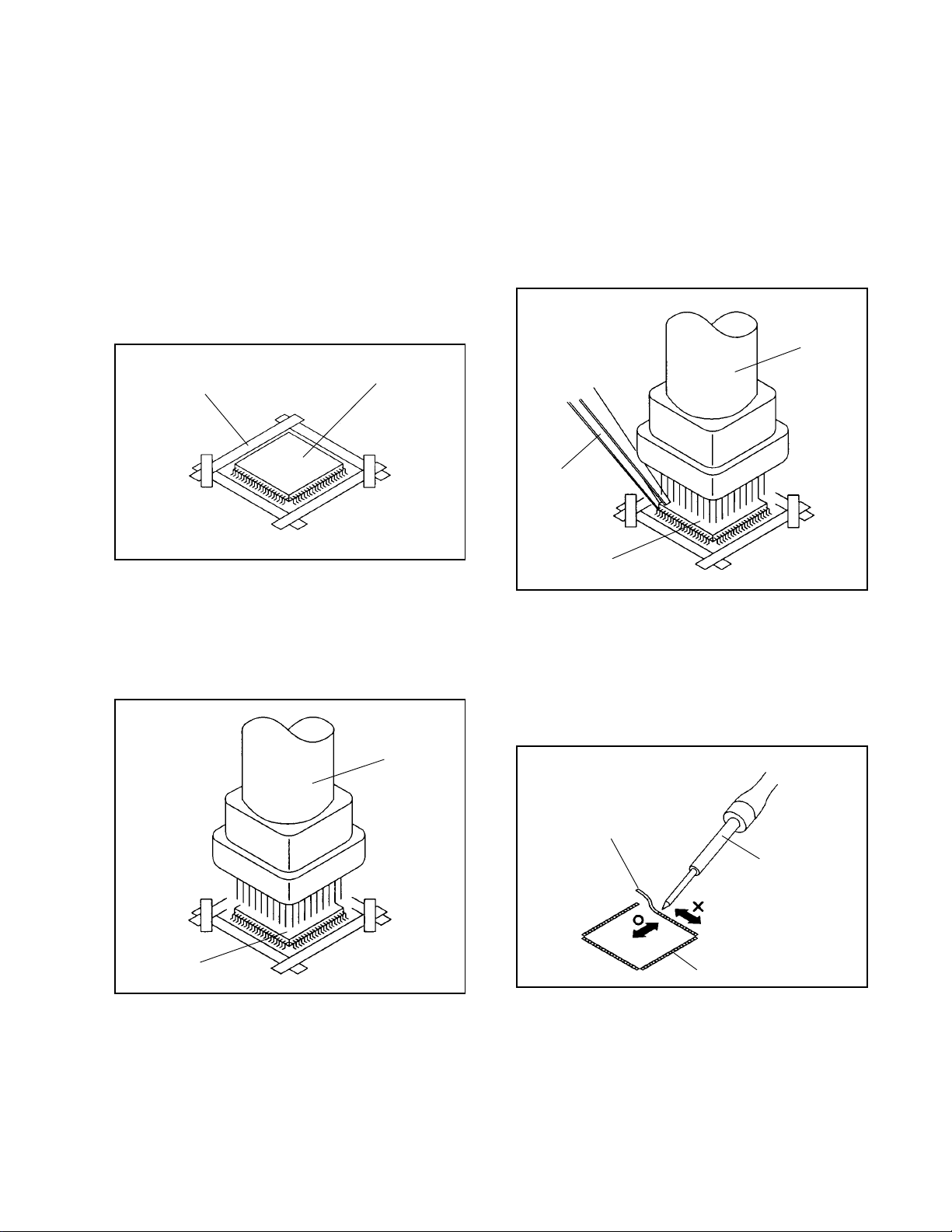
REMOVAL
Put the Masking Tape (cotton tape) around the Flat
1.
Package IC to protect other parts from any damage.
(Refer to Fig. 2-1.)
NOTE
Masking is carried out on all the parts located within
10 mm distance from IC leads.
When IC starts moving back and forth easily after
3.
desoldering completely, pickup the corner of the IC using
a tweezers and remove the IC by moving with the IC
desoldering machine. (Refer to Fig. 2-3.)
NOTE
Some ICs on the PCB are affixed with glue, so be
careful not to break or damage the foil of each IC
leads or solder lands under the IC when removing it.
Blower type IC
desoldering
machine
AV-14F702
Masking Tape
(Cotton Tape)
Heat the IC leads using a blower type IC desoldering
2.
IC
machine. (Refer to Fig. 2-2.)
NOTE
Do not add the rotating and the back and forth
directions force on the IC, until IC can move back and
forth easily after desoldering the IC leads completely.
Blower type IC
desoldering machine
Fig. 2-1
Tweezers
IC
Peel off the Masking Tape.4.
Absorb the solder left on the pattern using the Braided
5.
Shield Wire. (Refer to Fig. 2-4.)
NOTE
Do not move the Braided Shield Wire in the vertical
direction towards the IC pattern.
Fig. 2-3
Braided Shield Wire
Soldering Iron
IC
Fig. 2-2
IC pattern
Fig. 2-4
No.51912 5
Page 6
AV-14F702
DISASSEMBLY INSTRUCTIONS
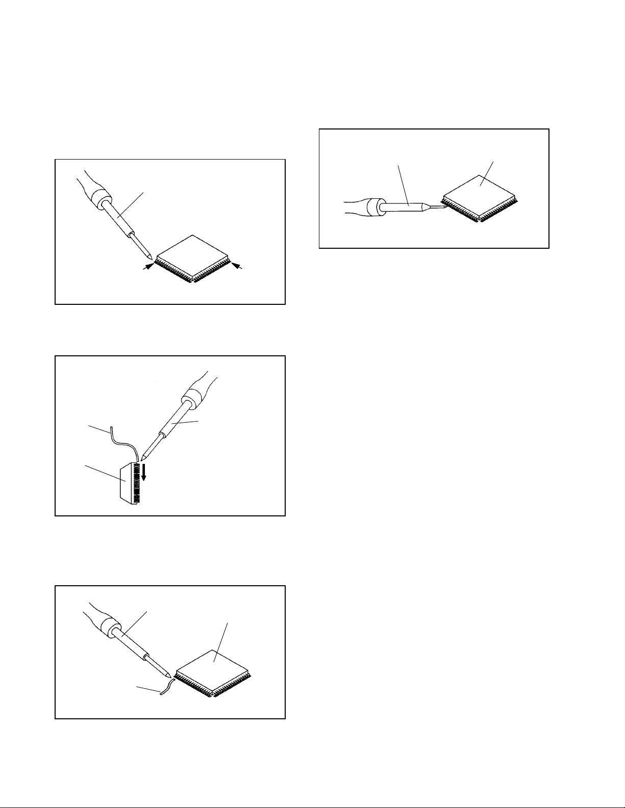
INSTALLATION
Take care of the polarity of new IC and then install the
1.
new IC fitting on the printed circuit pattern. Then solder
each lead on the diagonal positions of IC temporarily.
(Refer to Fig. 2-5.)
Soldering Iron
Solder temporarily
Supply the solder from the upper position of IC leads
2.
Solder temporarily
sliding to the lower position of the IC leads.
(Refer to Fig. 2-6.)
Fig. 2-5
When bridge-soldering between terminals and/or the
4.
soldering amount are not enough, resolder using a Thintip Soldering Iron. (Refer to Fig. 2-8.)
Thin-tip Soldering Iron
IC
Fig. 2-8
Finally, confirm the soldering status on four sides of the
5.
IC using a magnifying glass.
Confirm that no abnormality is found on the soldering
position and installation position of the parts around the
IC. If some abnormality is found, correct by resoldering.
NOTE
When the IC leads are bent during soldering and/or
repairing, do not repair the bending of leads. If the
bending of leads are repaired, the pattern may be
damaged. So, be always sure to replace the IC in this
case.
Soldering IronSolder
IC
Absorb the solder left on the lead using the Braided
3.
Supply soldering
from upper position
to lower position
Shield Wire. (Refer to Fig. 2-7.)
NOTE
Do not absorb the solder to excess.
Soldering Iron
IC
Braided Shield Wire
Fig. 2-6
Fig. 2-7
No.519126
Page 7

SERVICE MODE LIST
This unit provided with the following SERVICE MODES so you can repair, examine and adjust easily.
To enter the Service Mode, press both set key and remote control key for more than 1 second.
Set Key Remocon Key Operations
VOL. (-) MIN
VOL. (-) MIN 1
VOL. (-) MIN 6
0
Releasing of V-CHIP PASSWORD.
Initialization of the factory.
NOTE: Do not use this for the normal servicing.
POWER ON total hours is displayed on the screen.
Refer to the "CONFIRMATION OF USING HOURS".
Can be checked of the INITIAL DATA of MEMORY IC.
Refer to the "NOTE FOR THE REPLACING OF MEMORY IC".
AV-14F702
VOL. (-) MIN 8
VOL. (-) MIN
9
Writing of EEPROM initial data.
NOTE: Do not use this for the normal servicing.
Display of the Adjustment MENU on the screen.
Refer to the "ELECTRICAL ADJUSTMENT" (On-Screen Display Adjustment).
CONFIRMATION OF USING HOURS
POWER ON total hours can be checked on the screen. Total hours are displayed in 16 system of notation.
1.
Set the VOLUME to minimum.
2.
Press both VOL. DOWN button on the set and Channel
button (6) on the remote control for more than 1 second.
3.
After the confirmation of using hours, turn off the power.
ADDRESS DATA
INIT 00 83
CRT ON
0010
FIG. 1
Initial setting content of MEMORY IC.
POWER ON total hours.
= (16 x 16 x 16 x thousands digit value)
+ (16 x 16 x hundreds digit value)
+ (16 x tens digit value)
+ (ones digit value)
NOTE FOR THE REPLACING OF MEMORY IC
If a service repair is undertaken where it has been required to change the MEMORY IC, the following steps should be taken to
ensure correct data settings while making reference to TABLE 1.
+0 +1 +2 +3 +4 +5 +6 +7 +8 +9
E1 C3 02 00 31 B3 AF 37 9F A8
00 FF 04 00 00 00 4A
0F --- --- --- --- --- --- --- ---
10
---
+A
+B +C +D +E +FINI
--- --- --- --- --- ---
Table 1
Enter DATA SET mode by setting VOLUME to minimum.
1.
Press both VOL. DOWN button on the set and Channel button (6) on the remote control for more than 1 second.
2.
ADDRESS and DATA should appear as FIG 1.
ADDRESS is now selected and should "blink". Using the VOL. UP/DOWN button on the remote, step through the
3.
ADDRESS until required ADDRESS to be changed is reached.
Press ENTER to select DATA. When DATA is selected, it will "blink".
4.
Again, step through the DATA using VOL. UP/DOWN button until required DATA value has been selected.
5.
Pressing ENTER will take you back to ADDRESS for further selection if necessary.
6.
Repeat steps 3 to 6 until all data has been checked.
7.
When satisfied correct DATA has been entered, turn POWER off (return to STANDBY MODE) to finish DATA input.
8.
The unit will now have the correct DATA for the new MEMORY IC.
No.51912 7
Page 8

AV-14F702
SERVICE ADJUSTMENT
ELECTRICAL ADJUSTMENTS
1.
BEFORE MAKING ELECTRICAL
ADJUSTMENTS
Read and perform these adjustments when repairing the
circuits or replacing electrical parts or PCB assemblies.
CAUTION
•
Use an isolation transformer when performing any
service on this chassis.
•
Before removing the anode cap, discharge electricity
because it contains high voltage.
•
When removing a PCB or related component, after
unfastening or changing a wire, be sure to put the wire
back in its original position.
Inferior silicon grease can damage IC's and transistors.
•
When replacing IC's and transistors, use only specified
silicon grease.
Remove all old silicon before applying new silicon.
Prepare the following measurement tools for electrical
adjustments.
1. Oscilloscope
2. Digital Voltmeter
On-Screen Display Adjustment
In the condition of NO indication on the screen.
1.
Press the VOL. DOWN button on the set and the
Channel button (9) on the remote control for more than
1 second to appear the adjustment mode on the screen
as shown in Fig. 1-1.
TV
00 OSD 15
Fig. 1-1
Use the Channel UP/DOWN button or Channel button
2.
(0-9) on the remote control to select the options shown
in Fig. 1-2.
Press the MENU button on the remote control to end
3.
the adjustments.
2. BASIC ADJUSTMENTS
2-1: CONSTANT VOLTAGE
1.
Set condition is AV MODE without signal.
2.
Connect the digital voltmeter to TP002.
3.
Adjust the VR502 until the digital voltmeter is 115 ± 1V.
2-2: RF AGC
1.
Receive a 63dB monoscope pattern.
2.
Connect the digital voltmeter between the TP001 and
the GND.
3.
Activate the adjustment mode display of Fig. 1-1 and
press the channel button (02) on the remote control to
select "RF. AGC".
4.
Press the VOL. UP/DOWN button on the remote
control until the digital voltmeter is 2.50 ± 0.05V.
2-3: CUT OFF
1.
Adjust the unit to the following settings.
G. DRIVE=64, B. DRIVE=64, R. BIAS=32, G. BIAS=32,
B. BIAS=32, BRIGHTNESS=64, UNI COLOR=50.
2.
Place the set with Aging Test for more than 15 minutes.
3.
Activate the adjustment mode display of Fig. 1-1 and
press the channel button (01) on the remote control to
select "CUT OFF".
4.
Adjust the Screen Volume until a dim raster is obtained.
2-4: WHITE BALANCE
NOTE: Adjust after performing CUT OFF adjustment.
1.
Place the set with Aging Test for more than 10 minutes.
2.
Receive the white 100% signal from the Pattern
Generator.
3.
Using the adjustment control, set the brightness and
contrast to normal position.
4.
Activate the adjustment mode display of Fig. 1-1 and
press the channel button (13) on the remote control to
select "R. BIAS".
5.
Using the VOL. UP/DOWN button on the remote control,
adjust the R. BIAS.
6.
Press the CH. UP/DOWN button on the remote control to
select the "G. DRV", "B. DRV", "G. BIAS" or "B. BIAS".
7.
Using the VOL. UP/DOWN button on the remote control,
adjust the G. DRV, B. DRV, G. BIAS or B. BIAS.
8.
Perform the above adjustments 6 and 7 until the white
color is looked like a white.
NO.
00
01
02
03
04
05
06
07
08
09
10
11
12
13
14
15
16
FUNCTION
OSD H
CUT OFF
RF. AGC
--H. POSI
V. POSI
H. SIZE
V. SIZE
V. CENT
V. LIN
VS. CORR
G. DRV
B. DRV
R. BIAS
G. BIAS
B. BIAS
BRI
NO.
17
18
19
20
21
22
23
24
25
26
27
28
29
30
31
32
33
FUNCTION
SUBCONT
UNI COL
--TINT
SHARP
RGB CONT
PARABOLA
TRAPEZIU
COR TOP
COR BTM
V EHT
H EHT
FM. LVL
LEVEL
SEP1
SEP2
T. STE
Fig. 1-2
2-5: FOCUS
1.
Receive a 70dB monoscope pattern.
2.
Turn the Focus Volume fully counterclockwise once.
3.
Adjust the Focus Volume until picture is distinct.
2-6: HORIZONTAL POSITION
1.
Receive the center cross signal from the Pattern
Generator.
2.
Using the remote control, set the brightness and
contrast to normal position.
3.
Activate the adjustment mode display of Fig. 1-1 and
press the channel button (04) on the remote control to
select "H. POSI".
4.
Press the VOL. UP/DOWN button on the remote
control until the right and left screen size of the vertical
line becomes the same.
No.519128
Page 9

ELECTRICAL ADJUSTMENTS
AV-14F702
2-7: HORIZONTAL SIZE
NOTE: Adjust after performing adjustments in section 2-6.
1.
Receive the monoscope pattern.
2.
Using the remote control, set the brightness and
contrast to normal position.
3.
Activate the adjustment mode display of Fig. 1-1 and
press the channel button (06) on the remote control to
select "H. SIZE".
4.
Press the VOL. UP/DOWN button on the remote
control until the SHIFT quantity of the OVER SCAN on
right and left becomes 10 ± 2%.
2-8: VERTICAL POSITION
NOTE: Adjust after performing adjustments in section 2-7.
1.
Receive the center cross signal from the Pattern
Generator.
2.
Activate the adjustment mode display of Fig. 1-1 and
press the channel button (05) on the remote control to
select "V. POSI".
3.
Press the VOL. UP/DOWN button on the remote
control until the horizontal line becomes fit to the notch
of the shadow mask.
2-9: VERTICAL SIZE
NOTE: Adjust after performing adjustments in section 2-8.
1.
Receive the crosshatch signal from the Pattern
Generator.
2.
Activate the adjustment mode display of Fig. 1-1 and
press the channel button (07) on the remote control to
select "V. SIZE".
3.
Press the VOL. UP/DOWN button on the remote
control until the rectangle on the center of the screen
becomes square.
4.
Receive a broadcast and check if the picture is normal.
2-12: CORNER CORR TOP
1.
Receive the crosshatch signal from the Pattern
Generator.
2.
Using the remote control, set the brightness and
contrast to normal position.
3.
Activate the adjustment mode display of Fig. 1-1 and
press the channel button (25) on the remote control to
select "COR TOP".
4.
Press the VOL. UP/DOWN button on the remote control
until the upper section of the both ends vertical lines are
straight.
2-13: CORNER CORR BOTTOM
1.
Receive the crosshatch signal from the Pattern
Generator.
2.
Using the remote control, set the brightness and
contrast to normal position.
3.
Activate the adjustment mode display of Fig. 1-1 and
press the channel button (26) on the remote control to
select "COR BTM".
4.
Press the VOL. UP/DOWN button on the remote control
until the bottom section of the both ends vertical lines
are straight.
2-14: OSD HORIZONTAL
1.2.Activate the adjustment mode display of Fig. 1-1.
Press the VOL. UP/DOWN button on the remote control
until the difference of A and B becomes minimum.
(Refer to Fig. 2-1)
TV
2-10: PARABOLA CORR
1.
Receive the crosshatch signal from the Pattern
Generator.
2.
Using the remote control, set the brightness and
contrast to normal position.
3.
Activate the adjustment mode display of Fig. 1-1 and
press the channel button (23) on the remote control to
select "PARABOLA".
4.
Press the VOL. UP/DOWN button on the remote control
until the right and left vertical lines are straight.
2-11: TRAPEZIUM DIS
1.
Receive the crosshatch signal from the Pattern
Generator.
2.
Using the remote control, set the brightness and contrast
to normal position.
3.
Activate the adjustment mode display of Fig. 1-1 and
press the channel button (24) on the remote control to
select "TRAPEZIU".
4.
Press the VOL. UP/DOWN button on the remote control
until the both vertical lines of the screen become parallel.
00 OSD 15
A
2-15: LEVEL
1.
Receive a 70dB monoscope pattern.
2.
Connect the AC voltmeter to TP901.
3.
Activate the adjustment mode display of Fig. 1-1 and
press the channel button (30) on the remote control to
select "LEVEL".
4.
Press the VOL. UP/DOWN button on the remote
control until the AC voltmeter is 75 ± 2mV.
B
Fig. 2-1
No.51912 9
Page 10

AV-14F702
ELECTRICAL ADJUSTMENTS
2-16: SEPARATION 1, 2
Receive the stereo signal (L=2KHz, R=400Hz).
1.
Connect the AC voltmeter to AUDIO OUT JACK though
2.
stereo filter (L=400Hz, R=2KHz).
Activate the adjustment mode display of Fig. 1-1 and
3.
press the channel button (31) on the remote control to
select "SEP1".
Press the VOL. UP/DOWN button on the remote control
4.
until the output of L-CH and R-CH become minimum.
Press the CH UP button once the set to "SEP2" mode.
5.
Press the VOL. UP/DOWN button on the remote control
6.
until the output of L-CH and R-CH become minimum.
Press the CH DOWN button once the set to "SEP1"
7.
mode.
Repeat step 4 to step 7 several times.
8.
The output difference of the between with Filter and
without Filter should be more than 25dB for both L and R.
2-17: BRIGHTNESS
1.
Activate the adjustment mode display of Fig. 1-1 and
press the channel button (16) on the remote control to
select "BRI".
2.
Press the VOL. UP/DOWN button on the remote control
until the brightness step No. becomes "71".
3.
Press the INPUT button on the remote control to set to
the AV mode.
4.
Activate the adjustment mode display of Fig. 1-1 and
press the channel button (16) on the remote control to
select "BRI".
5.
Press the VOL. UP/DOWN button on the remote control
until the brightness step No. becomes "69".
6.
Press the INPUT button on the remote control to set to
the CS mode.
7.
Activate the adjustment mode display of Fig. 1-1 and
press the channel button (16) on the remote control to
select "BRI".
8.
Press the VOL. UP/DOWN button on the remote control
until the brightness step No. becomes "64".
2-20: SUB TINT/SUB COLOR
1.
Receive the color bar pattern. (RF Input)
2.
Connect the oscilloscope to TP806.
3.
Activate the adjustment mode display of Fig. 1-1 and
press the channel button (20) on the remote control to
select "TINT".
4.
Press the VOL. UP/DOWN button on the remote control
until the section "A" becomes a straight line
(Refer Fig. 2-2).
5.
Connect the oscilloscope to TP804.
6.
Press the CH DOWN button 3 times to set to
"SUBCONT" mode.
7.
Press the VOL. UP/DOWN button on the remote control
until the red color level is adjusted to 115% of the white
level. (Refer to Fig. 2-3)
8.
Receive the color bar pattern. (Audio Video Input)
9.
Press the INPUT button on the remote control to set to
the AV mode. Then perform the above adjustments
2~7.
10.
Press the INPUT button on the remote control to set to
the CS mode.
11.
Activate the adjustment mode display of Fig. 1-1 and
press the channel button (20) on the remote control to
select "TINT".
12.
Press the VOL. UP/DOWN button on the remote control
to increase the step numbers by 6 steps to the AV.
13.
Press the CH DOWN button 3 times to set to
"SUBCONT" mode.
14.
Press the VOL. UP/DOWN button on the remote control
to set the same step number as the AV.
2-18: UNI-COLOR
1.
Activate the adjustment mode display of Fig. 1-1 and
press the channel button (18) on the remote control to
select "UNI COL".
2.
Press the VOL. UP/DOWN button on the remote control
until the contrast step No. becomes "50".
3.
Press the INPUT button on the remote control to set to
the AV mode. Then perform the above adjustments 1,2.
4.
Press the INPUT button on the remote control to set to
the CS mode.
5.
Activate the adjustment mode display of Fig. 1-1 and
press the channel button (18) on the remote control to
select "UNI COL".
6.
Press the VOL. UP/DOWN button on the remote control
until the contrast step No. becomes "54".
2-19: VERTICAL LINEARITY
1.
Receive the monoscope pattern.
2.
Using the remote control, set the brightness and
contrast to normal position.
3.
Activate the adjustment mode display of Fig. 1-1 and
press the channel button (09) on the remote control to
select "V.LIN".
4.
Press the VOL. UP/DOWN button on the remote
control until the SHIFT quantity of the OVER SCAN on
upside and downside becomes minimum.
"A"
"A"
Fig. 2-2
White 100%
RED Level
Fig. 2-3
No.5191210
Page 11

ELECTRICAL ADJUSTMENTS
AV-14F702
3.
PURITY AND CONVERGENCE
ADJUSTMENTS
NOTE
1.
Turn the unit on and let it warm up for at least 30
minutes before performing the following adjustments.
2.
Place the CRT surface facing east or west to reduce the
terrestrial magnetism.
3.
Turn ON the unit and demagnetize with a Degauss Coil.
3-1: STATIC CONVERGENCE (ROUGH ADJUSTMENT)
1.
Tighten the screw for the magnet. Refer to the adjusted
CRT for the position. (Refer to Fig. 3-1)
If the deflection yoke and magnet are in one body,
untighten the screw for the body.
2.
Receive the green raster pattern from the color bar
generator.
3.
Slide the deflection yoke until it touches the funnel
side of the CRT.
4.
Adjust center of screen to green, with red and blue on the
sides, using the pair of purity magnets.
5.
Switch the color bar generator from the green raster
pattern to the crosshatch pattern.
6.
Combine red and blue of the 3 color crosshatch pattern
on the center of the screen by adjusting the pair of
4 pole magnets.
7.
Combine red/blue (magenta) and green by adjusting the
pair of 6 pole magnets.
8.
Adjust the crosshatch pattern to change to white
by repeating steps 6 and 7.
3-2: PURITY
NOTE
Adjust after performing adjustments in section 3-1.
1.
Receive the green raster pattern from color bar
generator.
2.
Adjust the pair of purity magnets to center the
color on the screen.
Adjust the pair of purity magnets so the color at the
ends are equally wide.
3.
Move the deflection yoke backward (to neck side)
slowly, and stop it at the position when the whole
screen is green.
4.
Confirm red and blue colors.
5.
Adjust the slant of the deflection yoke while watching the
screen, then tighten the fixing screw.
DEFLECTION YOKE
DEFLECTION YOKE SCREW
MAGNET SCREW
3-3: STATIC CONVERGENCE
NOTE
Adjust after performing adjustments in section 3-2.
1.
Receive the crosshatch pattern from the color bar
generator.
2.
Combine red and blue of the 3 color crosshatch pattern
on the center of the screen by adjusting the pair of
4 pole magnets.
3.
Combine red/blue (magenta) and green by adjusting the
pair of 6 pole magnets.
3-4: DYNAMIC CONVERGENCE
NOTE
Adjust after performing adjustments in section 3-3.
1.2.Adjust the differences around the screen by moving
the deflection yoke upward/downward and right/left.
(Refer to Fig. 3-2-a)
Insert three wedges between the deflection yoke and
CRT funnel to fix the deflection yoke.
(Refer to Fig. 3-2-b)
R G B
R
G
B
UPWARD/DOWNWARD SLANT RIGHT/LEFT SLANT
WEDGE
WEDGE POSITION
R
G
B
Fig. 3-2-a
WEDGE
WEDGE
Fig. 3-2-b
R G B
Fig. 3-1
PURITY MAGNETS
6 POLE MAGNETS
4 POLE MAGNETS
No.51912 11
Page 12

AV-14F702
MAJOR COMPONENTS LOCATION GUIDE
VR502
T501
TP002
TP001
TP901
TU001
J702
J701
J703
TP806
J704
J705
FB401
FOCUS VOLUME
SCREEN VOLUME
MAIN PCB
J801
TP804
CRT PCB
No.5191212
Page 13

GUIDE FOR REPAIRING
IC DESCRIPTION
SYSCON PCB OEC7055B(IC101)
NO. Symbol I/O Logi c Func tion Option
1 H.SY NC Input 0 Horizontal synchronization input 2 V. SYNC I n put 0 Ve r tica l sync hron i za t i o n i nput 3 - Input - Unused 4 REMOCON Input - Remote control input 5 - Input - Unused 6 SYNC Input - Synchronization detector input 7 KE Y1 I npu t - Vo lt ag e of th e TV butt on in put( po we r, vol do wn,c h do wn) C- M OS
8 KE Y2 I npu t - Vo lt ag e of th e TV butt on in put( vol up ,ch up ) C- M OS
9 X - RA Y I npu t - X - RA Y de tect or in put C- M OS
10 AFT I n put - Vo l ta g e of tu ning i n pu t C-MOS
11 - Input - Unused N-OD
12 - Input - Unused N-OD
13 - Input - Unused N-OD
14 - Output - Unused C-MOS
15 PO WE R FA IL I npu t 0 Powe r fa i l ur e dete ct or in put 16 - Input - Unused N-OD
17 - Input - Unused N-OD
18 AVCC - - Positive power supply for analog block (5v nom,) 19 HLF - - Fi lter for CCD 20 RVCO - - Resist or for CCD 21 VHO LD - - Capacit y for CCD 22 CV I N I - Vi deo si gn al for CC D 23 CNVSS - - Negative power supply for anal og bl ock (ground) 24 XI N Input - Ma in Oscillat ion (8MH z) 25 XO U T Ou tp ut - M ain Os c illat i o n ( 8 MHz) 26 VS S - - Nega ti ve po we r su pply for di gi ta l bl oc k ( gr oun d) 27 VC C - - Posi ti ve pow er supply for di gi ta l bl oc k (5 v nom, ) 28 OSC1 - In put Osci ll a tion for OSD 29 OSC2 - Output Oscillation for OSD 30 RESET Input 0 Reset signal input 31 AV 1 O - Ex t e r n al SW out o pu t1 C-MOS
32 AV 2 O - Ex t e r n al SW out o pu t2 C-MOS
33 ON TIMER O 1 On tim e r LED outp ut C-MOS
34 DE G AU SS H O 1 De ga uss ou tp ut C- M OS
35 SP OT OFF O 0 Sp ot killer ou tp ut C-MOS
36 - I - Unused N-OD
37 SDA I /O 1 Se r ia l data in pu t / ou t p ut N -OD
38 - I - Unused N-OD
39 SCL O 1 Se r ia l clock ou t p ut N-OD
40 HALF T ONE O 1 Half t o ne outp ut C -MO S
41 PO WE R O 1 Po wer cont ro l ou tput C- MO S
42 COMP H O 1 Component output C-MOS
AV-14F702
No.51912 13
Page 14

AV-14F702
IC DESCRIPTION
SYSCON PCB OEC7055B(IC101)
NO. Symbol I/O Logi c Func tion Option
43 I IC O FF I 0 Ser ial cloc k/data stop inpu t C-MOS
44 BB E H O 1 BBE c ont ro l ou tput C- M OS
45 TV MUTE O 0 Vo l u m e m u t ing ou tput fo r l ouds p eake r N-OD
46 EXT M UTE O 1 Vo l u m e m u t ing ou tp ut fo r exte r nal N-OD
47 - O - Unused N-OD
48 X RAY TEST O 1 X-RAY test output N-OD
49 BL O 1 Fa st blanking control signal C-MOS
50 B O 1 Bl ue out p ut of OS D C-MOS
51 G O 1 Green outp ut of OS D C-MOS
52 R O 1 Re d out p ut of OS D C-MOS
No.5191214
Page 15

NO POWER
AV-14F702
TROUBLESHOOTING GUIDE
Is the voltage at C501 DC24.0V ?
No
Is the voltage at pin 4 of
IC501 DC18V ?
No
Is the voltage at the point A in
the Figure DC170V ?
No
Is the voltage at the point B
in the Figure AC120V ?
No
Is the voltage at the point C
in the Figure AC120V ?
Yes
Yes
Yes
Yes
Yes
Check the circuit after C501.
Check IC501 and associated circuit.
Broken wire of R501 or short circuit
on GND.
Check D501 ~ D504 rectifying circuit.
Broken wire of L501.
IC501
T501
1
4
R501
A
B
C
D501~D504
L501
No
Is the voltage on both
ends of CP501 AC120V ?
No
Broken wire of AC cord or check
CP501.
Yes
F501
Broken wire of F501.
CP501
CD501
No.51912 15
Page 16

AV-14F702
TROUBLESHOOTING GUIDE
NO RASTER
Does the RASTER
appear at maximum
BRIGHT/CONTRAST ?
No
Is the high voltage of
ANODE 32KV ?
No
Is collector voltages
of Q405 DC2.8V and
Q402 DC17.3V ?
No
Yes
Yes
Yes
Is the voltage of pin 1 of
CP801 DC180V ?
No
Check the 180V line.
Is the heater voltage at
pin 10 of J801 AC6.3V ?
No
Check the HEATER circuit.
Yes
Yes
Check the output circuit and
associated circuit.
Contact defects of CRT or CRT
Socket.
Check FB401 and associated circuit.
Is the waveform at base
of Q405 normal ?
No
Is the waveform at pin
34 of IC201 normal ?
No
Check IC201 and associated circuit.
Yes
Yes
Broken wire of R439.
Check the circuit from pin 34 of
IC201 to Q402.
No.5191216
Page 17

NO COLOR
AV-14F702
TROUBLESHOOTING GUIDE
Are the waveforms at pins 3,
7 and 9 of J801 normal ?
No
Are the waveforms at pins 4,
5 and 6 of CP802 normal ?
No
Are the waveforms at
pins 14, 15 and 16 of
IC201 normal ?
No
Is the pulse of crystal
X601 normal ?
No
Yes
Yes
Yes
Yes
Defect of CRT or contact defects
of J801.
Check the output circuit and
associated circuit.
Check Q801, 802, Q803 and
peripheral circuit.
Check the associated circuit of IC201.
Check X601.
No.51912 17
Page 18

AV-14F702
TROUBLESHOOTING GUIDE
NO VERTICAL
Is the waveform at pin
6 of CP401 normal ?
No
Is the waveform at pin
5 of IC401 normal ?
No
Is the voltage pin 2 of
IC401 DC 25v ?
No
Broken wire of R431.
Yes
Yes
Yes
Is the waveform at pin
1 of IC401 normal ?
No
Check IC201 and peripheral circuit.
Yes
Check DY.
Check the circuit from pin 5 of
IC401 to CP401.
Check IC401 and peripheral circuit.
No.5191218
Page 19

NO SOUND
Is sound setting appropriate ?
Yes
AV-14F702
TROUBLESHOOTING GUIDE
Is the audio signal pins 7
and 12 of IC353?
No
Is the audio signal pins 2
and 5 of IC353?
No
Is the audio signal pins 7
and 14 of IC303?
No
Check the CHROMA IC, AV SW
IC and peripheral circuit.
Yes
Yes
Yes
Check SPEAKER.
Replace IC353 and check peripheral
circuit.
Check IC303 and peripheral circuit.
No.51912 19
Page 20

AV-14F702
TROUBLESHOOTING GUIDE
NO CCD
Does pin 22 of IC101
contain VIDEO signal ?
Yes
Is the Voltage pin 27
of IC101 DC 5v?
Yes
Does pin 1 of IC101
contain waveform ?
Yes
Defects on IC101.
No
No
No
Does pin 25 of IC701
feed VIDEO signal ?
Yes
Check the circuit from pin 22 of
IC101.
No
Check the associated circuit of IC701.
Check the circuit from Q501
and IC503.
Check the circuit from pin 1 of
IC101 to pin 9 of FB401.
No.5191220
 Loading...