

Page 1
SERVICE MANUAL
COLOUR TELEVISION
BASIC CHASSIS
CG
AV-14F4(NS)
This service manual mainly consists of the following items:
• The items which differ from those for the AV-14FT service manual.
• The initial value for each setting item.
For details other than those described in this manual, please refer to the following service manual.
Reference Service Manual: AV-14FT Service Manual (No. 56077, Sep. 2000)
A V-14FT
AV-14FT
Note: The page in parentheses shows the one for the AV-14FT service manual (No. 56077, Sep. 2000).
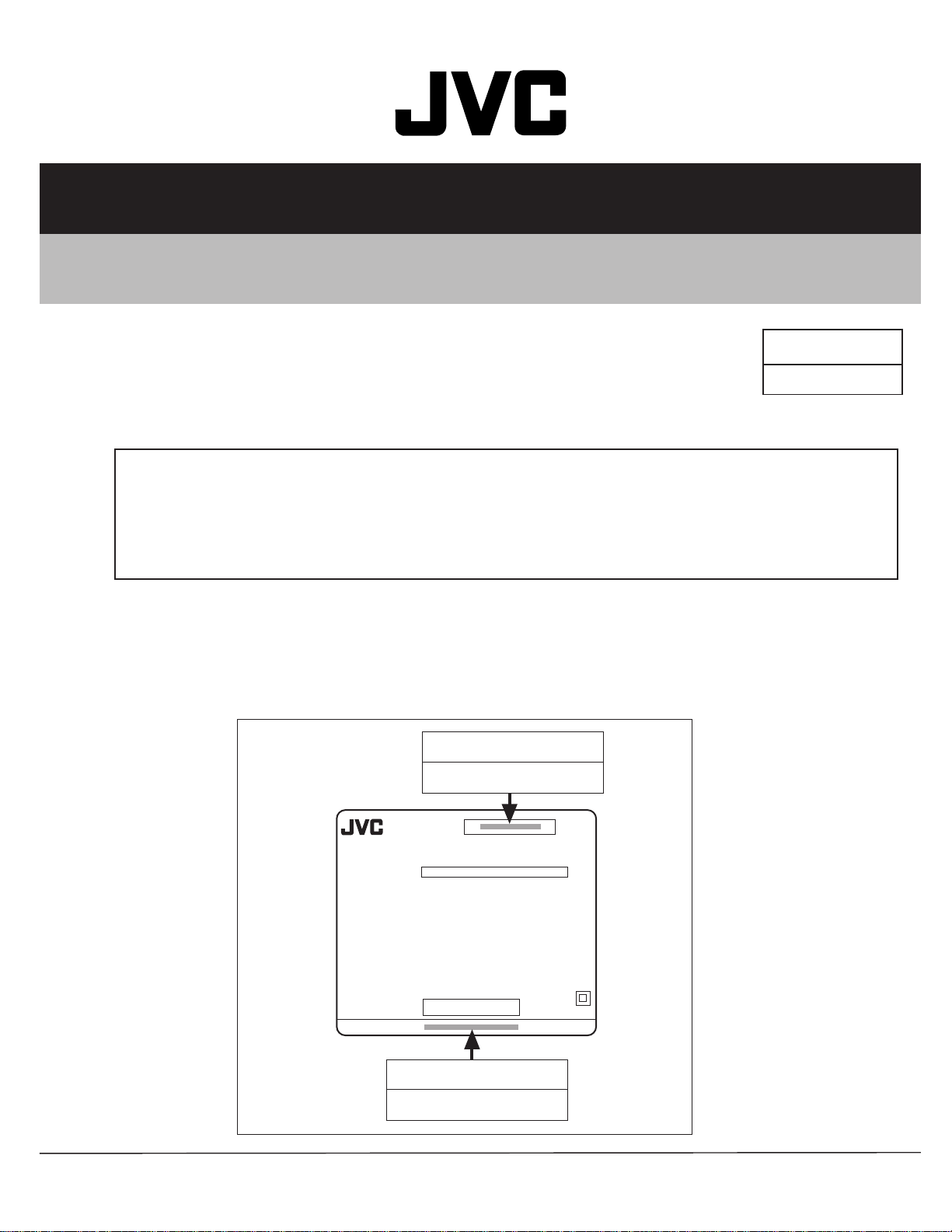
HOW TO IDENTIFY MODEL
While referring to the illustration given below, identify model name on the rating label affixed to the rear cover.
Basic model name
AV-14FT
MODEL NO.
XXXXX XXXXXXX
XXXXXXX XXXXX
XXXXXX
XXXXX
XXX XXXXX XXXXX
XXXXXXXXXXXXXXXXXXXXX
XXXXXXXXXXXXXXX
XXXXXXXXXXXXXXXXXXXXX
SERIAL No.
XXXX XX XXXX
XXX XX XXXX
XXXXXX–XXX
Identify model name
AV-14F4-NS
COPYRIGHT 2000 VICTOR COMPANY OF JAPAN, LTD.
No. 56082 1
No. 56082
Sep. 2000
Page 2
AV-14FT
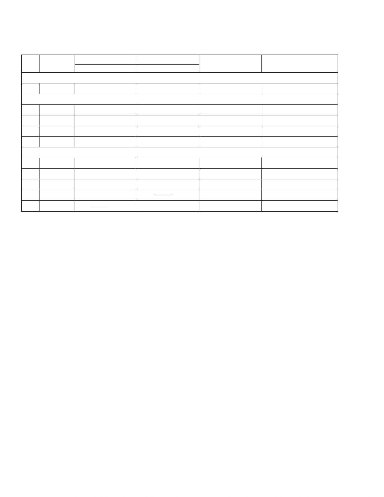
PARTS DIFFERENCE TABLE
The different parts between AV-14FT and AV-14F4(NS) are described below:
!!
! REF. NO. PART NAME DESCRIPTION
!!
AV-14FT AV-14F4(NS)
PART No. PART No.
■ EXPLODED VIEW PARTS LIST (Page 28)
! 17 LC20377-010B-H LC20377-016A-H RATING LABEL
■ PRINTED WIRING BOARD PARTS LIST (Page 30)
— SCG-1252A-H2 SCG-1260A-H2 MAIN PWB ASSY
TU1001 QAU0192-001 QAU0186-001 TUNER
IC1701 MN1873287JA MN1873287JC IC (MICROCOMPUTER)
IC1702 AT24C08-21FTR AT24C08-21F4BK IC (MEMORY) (Service)
■ PACKING PARTS LIST (Page 34)
1 GG10056-010A-H GG10056-030A-H PACKING CASE
5 RM-C364-1H RM-C367-1H REMOCON UNIT
! 7 LCT0757-001A-H LCT0770-001A-H INST BOOK
! 8 LCT0758-001A-H DIGEST MANUAL
— ATEAB001-00A MATCHING BOX
No. 560822
Page 3
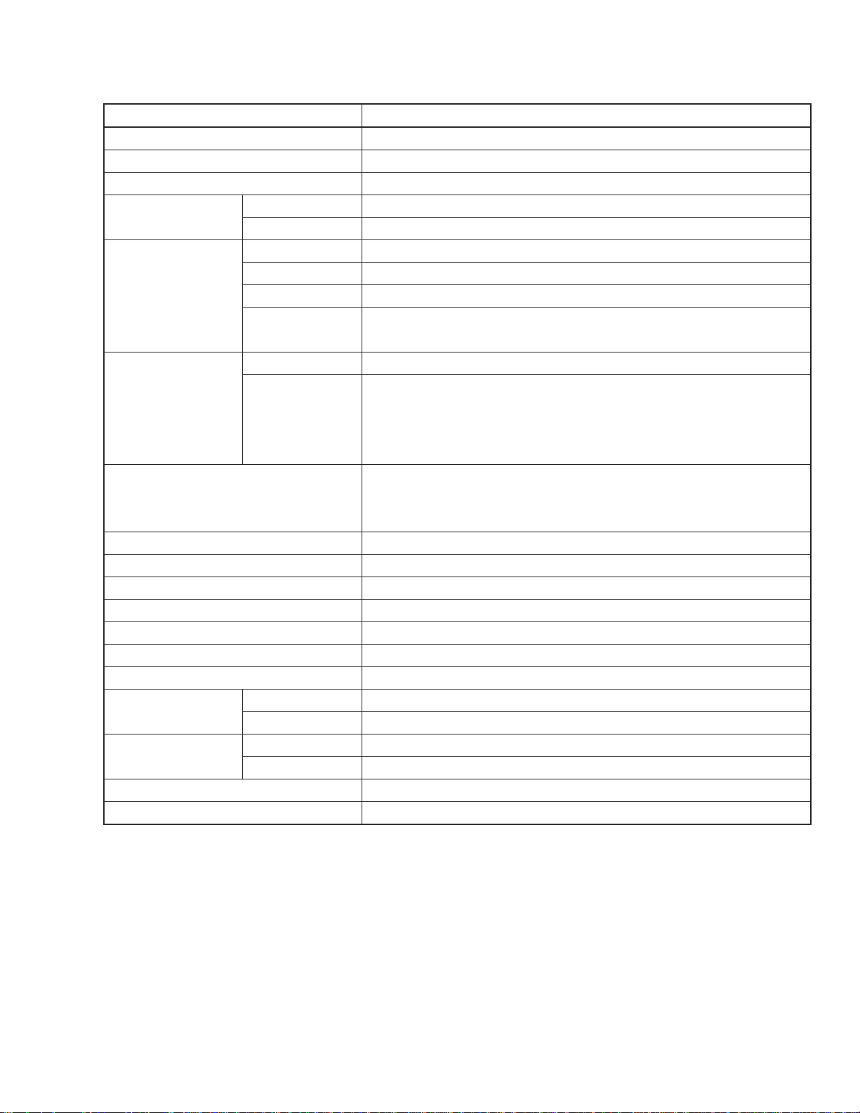
SPECIFICATIONS (Page 2)
Item Content
Dimensions (W × H × D) 462mm × 340.5mm × 375mm
Mass 10kg
TV RF System B / G, I, D / K, K1
Colour System TV Mode PAL / SECAM
VIDEO Mode PAL / SECAM / NTSC3.58 / NTSC4.43
Receiving Frequency VHF (VL) 46.25MHz ~ 168.25MHz
VHF (VH) 175.25MHz ~ 463.25MHz
UHF 471.25MHz ~ 863.25MHz
CATV ● Cable TVs of Mid (X-Z, S1-S10)
Super (S11-S20) & Hyper (S21-S41) bands receivable
Intermediate VIF Carrier 38.0MHz
Frequency 31.5MHz (6.5MHz)
SIF Carrier 32.0MHz (6.0MHz)
32.5MHz (5.5MHz)
33.5MHz (4.5MHz)
Colour Sub Carrier Frequency PAL (4.43MHz)
SECAM (4.40625MHz / 4.25MHz)
NTSC (3.58MHz / 4.43MHz)
Aerial Input Terminal 75Ω Unbalanced
Power Input AC110 ~ 240V, 50/60Hz
Power Consumption 70W (Max.) / 47W (Avg.)
Picture Tube Visible size : 34cm measured diagonally
High Voltage 22.5kV ± 1.5kV (at zero beam current)
Speaker 5cm × 9cm Oval type × 2
Audio Output 3W (Monaural)
Input Video 1Vp-p, 75Ω
Audio 500mVrms (−4dBs), High impedance
Output Video 1Vp-p, 75Ω
Audio 500mVrms (–4dBs), Low impedance
Headphone Jack Stereo mini jack (3.5ø)
Remote Control Unit RM-C367-1H (Battery size : AA/R06/UM-3 × 2)
A V-14FT
Design & specifications are subject to change without notice.
No. 56082 3
Page 4

AV-14FT
SPECIFIC SERVICE INSTRUCTIONS
SETTING OF SYSTEM CONSTANT SET (Page 7)
Table 1
Setting item Setting contents Setting value
COLOUR TRIPLE
BILINGUAL NO
TUNER MU
ECO SENSOR YES
LANGUAGE E
B/B SOUND OFF
LOCK 180
COLOUR AUTO NO
QSS MINT
ALC NO
TEXT RATE 20
AMP TUNER YES
VNR NO
MULTI. TRIPLE PAL
YES NO
MU MA
YES NO
E/T E
ON OFF
YES 10 20 ... 230
250 240
YES NO
MINT MQSS
YES NO
10 20 40 80
YES NO
YES NO
USER SETTING VALUES (Page 7)
Table 2
Setting item Setting value Setting item Setting value
SUB POWER ON PICTURE MODE (VSM) BRIGHT
CHANNEL POSITION 1 POSITION OFF TIMER OFF
CHANNEL PRESET
VOLUME Appropriate sound volume BLUE BACK OFF
TV/VIDEO TV ON TIMER PR1 0:00
ON SCREEN DISPLAY POSITION NUMBER DISPLAY CHILD LOCK OFF
COLOUR SYSTEM AUTO PAL PICTURE BOOSTER OFF
SOUND SYSTEM B / G
Refer to OPERATING
INSTRUCTION
AUTO SHUTOFF OFF
ECO SENSOR OFF
No. 560824
Page 5

SERVICE ADJUSTMENTS
■ Initial Setting Value
■ IF CIRCUIT ADJUSTMENT -- Adjustment of DELAY POINT (Page 15)
A V-14FT
Setting (Adjustment) Item
DELAY POINT
(AGC TAKE-OVER)
Variable Initial setting
range value
0 ~ 127 43
■ V/C (VIDEO/CHROMA) CIRCUIT ADJUSTMENT (Page 15)
[SUB MENU 2. V/C]
Colour system Variable Initial setting value
Setting item range PAL SECAM NTSC 3.58 NTSC 4.43
1. CUT OFF (R / G / B) −128 ~ +127 −50 bbb
2. DRIVE (R / B) −64 ~ +63 0 bbb
3. BRIGHT −128 ~ +127 0 bbb
4. CONT. −64 ~ +63 0 bbb
5. COLOUR (P / S / N3 / N4) −64 ~ +63 0 bbb
6. TINT (N3 / N4) TV / VIDEO −64 ~ +63 0 / +80 / 0
7. SECAM BL ADJUST −32 ~ +31 0 bbb
8. SHARP TV / VIDEO −32 ~ +31 −15 / +5 bbb
9. AMP T. SHARP −16 ~ +15 0 bbb
: Do not adjust.
Adjustment of SUB COLOUR-II (Page 18)
Adjustment part Description
5. COLOUR
PAL COLOUR Value (A) in the figure: Set to +9V (W & G).
SECAM COLOUR Value (A) in the figure: Set to +3V (W & G).
NTSC 3.58 COLOUR Value (A) in the figure: Set to +9V (W & G).
Adjustment of SUB TINT-II (Page 19)
Adjustment part Description
6. TINT
NTSC 3.58 TINT Value (B) in the figure: Set to +7V (W & Cy).
No. 56082 5
Page 6

AV-14FT
■ DEFLECTION CIRCUIT ADJUSTMENT (Page 20)
[SUB MENU 4. DEF]
Setting item Adjustment name Variable range
1. VER. POSITION Vertical center −4 ~ +3 −2 −3
2. HOR. POSITION Horizontal center −16 ~ +15 +1 +4
3. VER. HEIGHT Vertical height −64 ~ +63 −40 0
4. VER. LINEARITY Vertical linearity −32 ~ +31 +13 −3
5. VER. SCURVE Vertical scurve −32 ~ +31 −32 0
6. HOR. VCO ADJUST Horizontal VCO −64 ~ +63 0 0
: Do not adjust.
Initial setting value
50Hz 60Hz
■ VSM PRESET ADJUSTMENT (Page 22)
[Setting Values for SUB MENU 4. VSM PRESET]
VSM preset
VSM mode BRIGHT STANDARD SOFT
Setting item
TINT
SETTING VALUE
COLOUR
SETTING VALUE
BRIGHT
SETTING VALUE
CONT.
SETTING VALUE
SHARP
SETTING VALUE
+15
+15
+15
+30 +15 +11
+15 +15 +12
bb
b
bb
bb
b
bb
bb
b
bb
bb
b
bb
bb
b
bb
bb
b
bb
: Do not adjust.
No. 560826
Page 7

A V-14FT
■ PRESET ADJUSTMENT (Page 23)
[SUB MENU 5. PRESET]
Colour system Initial setting value
Setting item PAL SECAM NTSC 3.58 NTSC 4.43
1. C-TRAP FIX 1 bbb
2. SHARP PEAK 0 b
3. ABL 1 b
4. GAMMA 0 bbb
5. Y.DELAY TIME TV 0 2 2 3
VIDEO 0 2 0 2
6. BLACK EXP START 3 bbb
7. C-BPF TV 1 b 0 b
VIDEO 1 bbb
8. CW/SCP 0 bbb
9. V.IF DET. LEVEL 0 bbb
11. IF AGC MIN. 0 bbb
12. V.IF AGC 0 bbb
13. V.IF PMOD 0 bbb
19. VNR 15 bbb
20. RGB LIM. 1 bbb
21. RGB LIMIT LEVEL 2 bbb
23. TEXT H. POSITION −3 bbb
24. READ DATA
: Do not adjust.
TV RF system Initial setting value
Setting item B/G I D/K M
10. S.IF DET. LEVEL 0 bbb
14. S.IF BPF BW ADJUST 0 bbb
15. S.IF TRAP FO ADJUST 0 bbb
16. S.IF TRAP FO ADJUST 2 0 bbb
17. S.IF-TRAP 0 bbb
18. S.IF-BPF 0 bb 1
22. S.IF SW 1 bb 0
: Do not adjust.
No. 56082 7
Page 8

AV-14FT
VICTOR COMPANY OF JAPAN, LIMITED
TELEVISION RECEIVER DIVISION 1106 Heta, Iwai-city, Ibaraki-prefecture, 306-0698, Japan
No. 560828
AV14F4NS-H #3
CTH 0009
CRT
 Loading...