

Page 1
SCHEMATIC DIAGRAMS
COLOUR TELEVISION
BASIC CHASSIS
AV-21D43/BK
AV-20N43/BK
AV-21D43
AV-20N43
AV-14F43
CG
[RM-C368GY]
[AV-14F43
AV-14F43/BK
CD-ROM No.SML200209
/BK] [AV-20N43/BK] [AV-21D43/BK]
CONTENTS
NOTE ON USING CIRCUIT DIAGRAMS
SEMICONDUCTOR SHAPES
BLOCK DIAGRAM
CIRCUIT DIAGRAMS
PATTERN DIAGRAMS
COPYRIGHT 2002 VICTOR COMPANY OF JAPAN, LTD.
2-1
2-2
2-3
2-5
2-13
No.52036
Aug. 2002
Page 2
AV-21D43
STANDARD CIRCUIT DIAGRAM
AV-21D43
/BK
AV-20N43
/BK
AV-14F43
/BK
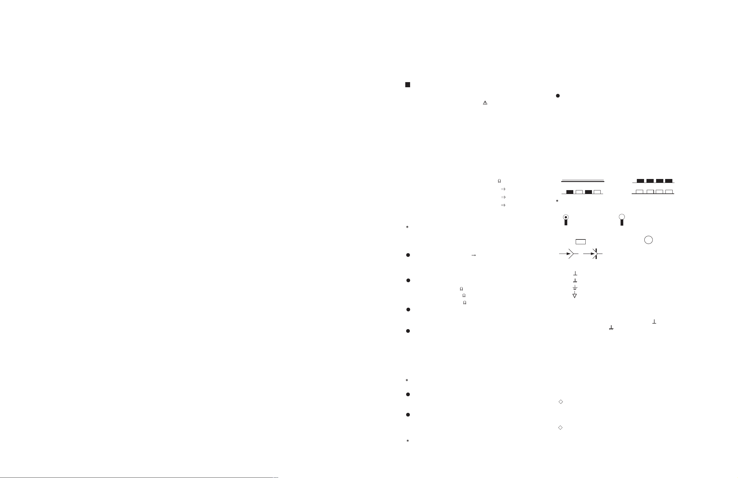
NOTE ON USING CIRCUIT DIAGRAMS
1.SAFETY
The components identified by the symbol and shading are
critical for safety. For continued safety replace safety critical
components only with manufactures recommended parts.
2.SPECIFIED VOLTAGE AND WAVEFORM VALUES
The voltage and waveform values have been measured under the
following conditions.
(1)Input signal : Colour bar signal
(2)Setting positions of
each knob/button and
variable resistor
(3)Internal resistance of tester
:DC 20k
/V
(4)Oscillosco pe swe eping time
:H
20µS/div
:V
5mS/div
:Others
Sweeping time is
specified
(5)Voltage values
:All DC voltage values
Sin ce th e vo l tage val ue s of si gn a l cir cui t va ry to some ex ten t
according to adjustments, use them as reference values.
3.INDICATION OF PARTS SYMBOL [EXAMPLE]
In the PW board
:R1209
R209
4.IND ICATIONS ON THE CIRCUIT DIAGRAM
(1)Resistors
Resistance value
No unit :[
]
K
:[K
]
M
Rated allowable power
No indication :1/ 16 [W]
Others :As specified
Type
No indic ation
:Carbon resistor
OMR
:Oxide metal film resistor
MFR
:Metal film resisto r
MPR
:Metal plate resistor
UNFR
:Uninflammable resi stor
FR
:Fusible resistor
C omposition r esistor 1/2 [W] is specified as 1/2S or Comp.
(2)Capacitors
: Original setting position
when shipped
5.NOT E FOR REPAIR ING S ERVI CE
This model's power circuit is partly di fferent in the GND. The
difference of the GND is shown by the LIVE : ( ) side GND and the
ISOLATED(NEUTRAL) : ( ) side GND.Therefore, care must be
taken for the following points.
(1)Do not touch the LIVE side GND or the LIVE side GND and the
ISOLATED(NEUTRAL) side GND simultaneously. If the above
caution is not respected, an electric shock may be caused.
Therefore, make sure that the power cord is surely removed from
the receptacle when, for example, the chassis is pulled out.
(2)Do not short between the LIVE side GND and ISOLATED(NEUTRAL)
side GND or never measure with a measuring apparatus measure
with a measuring apparatus ( oscilloscope, etc.) the LIVE side GND
and ISOLATED(NEUTRAL) side GND at the same time.
If the above precaution is not respected , a fuse or any parts will be broken.
Since the circuit diagram is a standard one, the ci rcuit an d
circuit constants may be subject to change for improvement
without any notice.
NOTE
Due improvement in performance, some part numbers show
in the circuit diagram may not agree with those i ndicated in
the part list.
When ordering parts, plea se use the numbers t hat appear
in the Parts List .
Type
MM
:M etal ized mylar capa c i tor
PP
:Polypropylene capacitor
MPP
:Metalized polypropylene capacitor
MF
:Metalized film capacitor
TF
:Thin film capacitor
BP
:Bipolar electrolytic capacitor
TAN
:Tant alum capacit or
(3)Coils
No unit
:[
µ
H]
Others
:As specified
(4)Power Supply
:B1
:9V
:5V
Respective voltage values are indicated
(5)Test point
:T est point
:Only test point display
(6) Connecting method
:Connector
:Wrapping or sold eri ng
:Receptacle
(7)Ground symbol
:LIVE side ground
:ISOLATED(NEU TRAL) side ground
:EARTH ground
:DIGITAL ground
:[M ]
Capacitance value
1 or higher :[pF]
less than 1
:[µF]
Withstand voltage
No indication :DC50[V]
Others :DC withstand voltage [V]
AC indicated
:AC withstand voltage [V]
Electrolytic Capacitors
47/50[Example]:Capacitance value [µF]/withstand voltage[V]
No indication
:Ceramic capacitor
:B2 (12V)
AV-20N43
AV-14F43
AV-21D43
AV-20N43
AV-14F43
No.52036
Aug. 2002 No. 520362-16
Page 3
AV-21D43
AV-20N43
AV-14F43
CONTENTS
AV-21D43
AV-20N43
AV-14F43
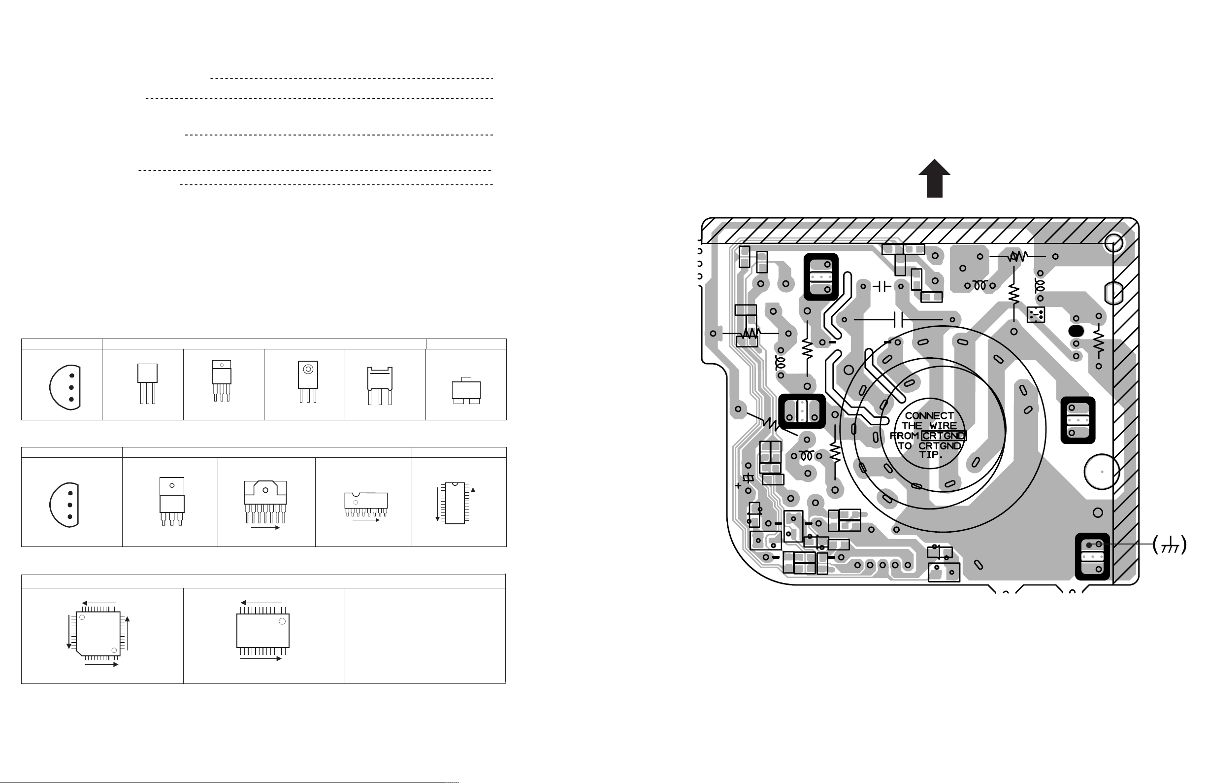
CRT SOCKET PWB PATTERN
SEMICONDUCTOR SHAPES
BLOCK DIA GRAM
CIRCUIT DIAGRAMS
MAIN PWB CIRCUIT DIAGRA M
P ATTERN DIAGRAMS
MAIN PW B PATTERN
CRT SOCKET PWB PATTERN
SEMICONDUCTOR SHAPES
TRANSISTOR
BOTTOM VIE W
E
C
B
ECB
BCE
(G)(D)(S )
FRONT VIEW
ECB
ECB
TO P VI EW
CHIP TR
C
BE
2-2
2-3
2-5
2-13
2-15
TOP
8
6
3
W270
E
5
3
R
C354
3
6
3
R
5
3
R
-4
P
T
R366
Q351
B
4
C
7
L351
/R
G
7
R360
SCREEN
T
G2
R
/G
R
7
-4
P
3
C
3
C
6
3
3
W
5
G2
R
3
5
3
R356
1
5
R359
2
RK
GK
B
5
6
3
BK
R362
R
L354
MARK
1
R369
4
U
NEAMX5 94V-0
C
E
6
5
3
C
HE
Q353
H
3
5
3
L
IC
B O TT OM VI EW F R O NT VIEW TO P VI EW
OUT
E
IN
IN OUTE
1 N
1 N
CHIP IC
TO P VI EW
N
N
N
1
N
1
N
R364
R346
1
N
C357
D356
W
R
R
D352
7
3
3
R351
B
5
4
3
2
5
3
3
5
3
D
6
7
5
W
3
R
R349
3
L
2
5
C
Q352
R3
E
7
4
8
4
3
R
GK
R361
55
C
W338
RK
G1
G1
5
5
3
8
5
3
R
1
5
3
K
4
5
3
D
R
A
M
7
6
3
R
5
HE
5
5
3
D
T
K
1
SK351
BK
H
2
H
-E
9
4
3
1
F
K
C
D351
G1
TP-47B
E1
-1
1
\4
/2
2
0
\4
TP-E
2-2
No.52036No.52036
2-15
Page 4

BLOCK DIAGRAM
IC702
MEMORY
TU001
TUNER
SCL
SDA
IF
37.38
SCL
SDA
IC701
MICRO COMPUTER
Q102
IF AMP
SCL/SDA
SF102
SF122
IC703
5V REG & RESET
AV-21D43
AV-20N43
AV-14F43
18.19 21
SAW QSS
VIDEO
VIDEO
OUT
IN
24
36
IN
IC301
1 CHIP DECODER
AUDIO
IN
29
AV-21D43
AV-20N43
AV-14F43
H.OUT V .OUT
42
30
AUDIO
OUT
AUDIO AMP
AUDIO
RGB
46
IC651
3
10.11.12
SP
OUT
8
ECO
REMOCON
KEY
IND.
HEAD
PHONE
FRONT
IN
VIDEO
AUDIO
CRT SOCKET PWB
SP
REAR
VIDEO
IN
AUDIO
VIDEO
OUT
AUDIO
AC IN
POWER SW
F901
LF901
D901
RECT
IC921
POWER
REG.
T921
SW
TRANSF.
H.OUT
IC971
5V REG.
9V REG.
V .OUT
Q522
H.OUT
5V REG.
9V REG.
MAIN PWB
B1
IC421
VERT.OUT
R / G /B
T522
HVT
RGB
DRV
FOCUS
SCREEN
EHV
V01
CRT
DY(V)
DY(H)
DEF.YOKE
No.52036
2-3 2-4
No.52036
Page 5

CIRCUIT DIAGRAMS MAIN PWB CIRCUIT DIAGRAMS (1/2) [AV-21D43/BK, AV-20N43/BK]
Q701
X
FRONT
A_IN
J006
X
V_IN A_IN
J003
CEMN065-001
OR
QNN0281-003 QNN0281-002
J002
QNN0384-001
V_IN
A_IN
V_OUT
A_OUT
REAR
R802
75
C842
X
C806
470/16
R796
10k
TRESET
TDA
TEXT/OTH
C727
R747
Q704
X
R746
10k
R717
C805
220/16
R807
Q804
*1
D705
SLR-342MG-T16
D704
L-132XID-T16
R749
4.7k
R745
X
R750
X
D707
*4
XC732
0.2V 5V 0V 0.3V 0.3V 0.2V 2.5V 0V 5V 3.1V 4V 5V 5V
A
H
T
D
T
/O
T
X
E
T
F
T
F
C
/O
E
T
X
0
1500p
68
R815
180
1/2W
Y
A
R
_
X
X
0.2V
C841
C712
.01
CEMN065-002
0V
N
O
O
R
_
P
P
6
2
X
7
C
Y704
0
F
F
T
/O
O
N
R
O
.P
_
A
P
N
E
V
/E
D
D
O
C832
X
0V 0V 0V 0V 0V 0.2V 0.8V 5V 5V 5V0V 2.5V 2.5V
/
R
N
D
0
E
D
C
V
O
E
E
E
R
F
_
2
L
S
C
U
B
S
NC NC NC NC NC NC NC NC NC NC NC NC NC NC NC NC
C847
X
J004
OR
VIDEO
AUDIO
R810
56 1W OMR
QRG01GJ-560
Q803
2SC1815/YG/-T
8.2V
4.7V
LINE_V
4V
R806
270
1/2W
C811
10/50
680R816
LINE_A
R817
4.7k
0.2V
A_MUTE
C812
X
POWER
E
L
T
O
U
V
R771
M
2.2k
_
A
R748
22k
D706
*4
C738 BW
22/50
C731
X
L
T
T
F
E
F
E
X
T
O
S
E
U
V
/O
T
M
_
A
K
C
O
L
9
k
1
1
7
R
5
4
X
8
R
s
Y
_
D
S
O
2
A
D
S
220R811
E
N
R
O
C
L
A
H
C
H
T
N
T
/O
Y
8
/O
S
_
.5
.5
H
3
4
0V 0V 0V0V 0V
1
1
5
X
2
.0
.0
7
C
0
8
2
1
7
7
C
C
R722
X
H
T
/O
8
.5
3
I/II
G
B
S
_
_
Y
T
T
_
X
X
T
E
E
X
T
T
E
T
X
X
X
7
8
6
3
3
3
8
8
8
C
C
C
4
2
7
4
4
4
X
X
X
8
8
8
R
R
R
3
1
9
4
4
3
X
X
X
8
8
8
R
R
R
B
R
G
_
_
_
D
D
D
S
S
S
O
O
O
1
1
L
A
C
C
D
S
S
N
C848
X
R734
R706
R
_
T
X
E
T
0
4
8
R
TEXT_R
GO
TEXT_G
TIMER
R721
R726
10k
4.7k
R772
820
R773
1.2k
Q708
R740
3.9k
NC NCNC
7
3
X
7
C
R708
1k
X
560
C743
X
G
_
D
S
O
*3
R741
560
.01C744
0V
/V
V
T
!
IC701
*
s
Y
B
_
_
D
D
S
S
O
O
I/II
4
5
3
3
3
3
X
X
X
7
7
7
C
C
C
9
0
k
k
0
1
7
7
.7
.7
R
4
R
4
BW
S
B
G
Y
_
_
_
D
D
D
S
S
S
O
O
O
Q821
X
INVERTER
R833
X
INVERTER
L
A
D
C
T
T
2
5
3
2
X
X
8
8
R
R
K
S
S
V
C
H
O
L
C
T
E
H
L
T
B
/O
A
1
N
T
.E
C
X
E
N
M
0V 0V 0V 0V
L821
X
O
R
R
_
D
S
Y371
O
BW
C371
X
5V
R1 R2
1.3V 1.3V 1.3V 1.3V 1.3V
R377XR380
X
R737
Q710
100k
*3
]
]
D
N
G
G
_
D
S
O
C843
A
T
A
D
T
S
S
V
2
7
3
Y
T
F
W
IM
A
O
[T
[P
D
E
D
L
E
L
R
_
D
T
S
C
S
O
N
R
NC
C736
X
R725
3
1k
1
7
R711
C
4.7k
R718
560
R707
560
C741
BW
C742
R
BW
_
D
S
O
R835
R846
X
X
C833
C835
X
X
R834
X
Q822
X
R849
X
X
TEXT/OTH
XR848
C844
X
C845
H
T
/O
T
X
E
IC821
T
X
1
2
L
L
D
A
A
T
T
D
X
X
V
5V 2.4V
2.6V 5V 2.5V 5V
X821
X
C824
C823
X
C822
C825
X
B
O
B
_
B
_
D
T
S
X
O
E
T
3
7
0
3
Y
1.3V1.3V1.3V1.3V 3.3V3.3V3.3V
AB2B1BOROVDD
IC371
X
G1 GO G2 INH VEE VSS
0V 0V 0V
0
R381
R378
X
X
No.52036 No.52036
VOL+ VOL-
C721
.033
2
Y
IN
E
O
K
C
E
K
C
C
N
Y
O
L
S
_
C
V
T
p
0
7
8
1
1
7
C
1
1
W
0
.0
B
7
K
6
0
1
2
7
2
R
L
C
T
R838
X
R837
X
Q824
X
INVERTER
R836
X
C834
X
EF801
X
C
N
T
C
S
N
R
X
X
ODD/EVEN
CB
H
C
1
Y
E
K
1
A
D
S
C846
D
D
V
E
T
U
M
_
A
V
T
R729
S701-S705 QSW0619-003Z
CH+ CH-
S
Y
_
T
X
E
T
R373
Q372
R374
6.8k
X
0V
R727
15k
2
L
C
S
1
C
S
O
2
Y
E
K
1
H
T
/O
L
R384
X
X
180p
2
A
D
S
2
C
S
O
2.4V2.4V0.2V 4V 5V 4.8V 5V 4.4V 4.4V
X701
FCR12.0M2S
100/16
C830
X
1
Y
E
K
2
H
T
/O
L
X
D372
X
9V 9V
0V 0V
XR375
C714
33p
CH
C710
Q373
Q371
S704S701
R731
4.7k
N
O
C
O
M
E
R
S
S
V
0V
C831
R831
C839
C829
W
O
L
S
H
T
/O
L
.V
L
X
X
S702 S703
R736
82k
R728
1k
C730
.01
C728
1k
CH
0V
4.8V 4.8V 4.5V
E
C
E
N
R
F
_
S
U
B
1
L
D
C
D
S
V
5V5V5V 5V 5V
C715
H
33p
C
CH
p
6
0
1
8
7
1
C711
C
.01
Y705
BW
R715
220
1
1
L
A
C
D
S
S
C849
INVERTER
Q825
X
X
C821
X
0V
S
N
S
O
V
C
O
M
E
R
E
T
U
L
M
_
O
A
V
R827
X
XR379
XR382
Ys SW
R376
X
N
E
V
/E
D
D
O
C729
180p
CH
Z
6
R
-5
J
4
4
2
L
Q
Q
BUS_FREE
X
X
X
X
T
F
A
D
N
G
XD373
XR385
Ys SW
0V
V
5
K703
K704
BW
.6
5
1
0
7
L
R705
220
S
B
V
C
K
C
O
L
XR383
Y374
R730
R828
C826
0
MENU
S705
10k
F
E
IR
A
S
S
V
X
X
W
P
_
B
T
S
IR DETECT UNIT
D
N
G
0V 5V 5V
4.8V
4.8V
0V
5V
C709
.01
R738
10k
C722
100p CH
4V
0V
0V
Q702
*1
R714
4.7k
R720
4.7k
R713
4.7k
R712
4.7k
2
2
L
A
R704
D
C
220
S
S
PIC_MUTE
R332
C334
X
X
LINE_V
R333
L331
N
X
X
C335
X
0
3
X
8
R
C828
X
NCNCNCNCNCNCNCNCNC
5V1.5V3V
A
C
D
N
D
V
3
C
IL
F
N
R829
X
C827
X
TRESET
TEXT/OTH
S
Y
_
D
S
O
0R372
F
D
W
N
P
_
G
_
B
A
T
S
D
N
G
_
A
T
C
Y
F
A
O
C
R
R
V
/O
_
_
N
.P
X
A
A
O
_
P
F
T
C
Y
F
A
O
C
R
R
V
/O
_
_
N
.P
X
A
A
O
_
P
AV-21D43
AV-21D43
AV-20N43
AV-20N43
AV-14F43
IC704
PIC-28143SY
T
c
U
c
V
O
C719
1/50
IC702
AT24C08-21D43BK
VSS
SDA
S
C
L
NP
VDD A0
R739
10k
Q703
4.7V
*1
0V
0V
R742
56k
C724
56p
R797
15k
T
P
C
U
B
C
F
V
O
_
_
H
H
T
T
P
C
U
U
B
C
F
O
V
O
_
_
_
V
H
H
R703
3.9k
D701
Q709
*4
*2
C701
10/50
R701
5.6k
0V
0V
A2
0V
A1
0V
W
B
1
0
7
P
C
!
W
P
_
B
T
S
SDA1
FBP
D795
T
C
U
N
Y
O
_
S
_
V
V
V
C
9
N
Y
S
_
V
IC703
L78LR05E-MA
5V REG&RESET
D
N
D
IN
C
G
10.7V 5.9V 0V 5V 5V
C706
C705
.01
470/16
P
C
0
7
3
2
7
-2
7
2
3
R
2
0
9
Z
R
Q
T
F
A
E
T
U
M
_
IC
P
D731
*4
Y975
Y001
Y002
X
V_SYNC
X
X
BW
SCL1
1
L
C
S
FBP
R308
1.8k
P
B
F
P
P
V
0V 0V 0V 0V
220R301
C301
.012
2
1
2
L
A
A
C
D
D
S
S
S
D794
2
3
4
1
X
9
9
9
9
7
7
7
7
R
R
R
R
CN00C
X
2-5 2-6
AV-21D43
AV-21D43
AV-20N43
AV-20N43
AV-14F43
SP01
*
PC701
P1241-04
ECO SENSOR
C707
R307
1.2k
6
0
3
R
.01
T
E
S
E
R
100/16
0
2
2
A
D
S
R702
6.8K
T
U
O
V
5
47/25
IC652
SI-5003X-X
47/50C501
.01C502
10/50C503
100 1/2WR501
C308
0V
S
S
V
C708
A_GND
C309
.01
P
C
S
!
J005
QNS0165-001
HEADPHONE
R662
270
1/2W
QRX029J-4R7
V
.5
3
2
V
.6
3
2
A_VCC
RB100A-T2
QETM1CM-227
C504
220/16
V_OUT
R401
10k
TFC401
.47
5V
]
C
V
G
[5
D
.A
r
D
e
V
V
R654
4.7
V
V
0
0
V
.5
3
2
V
V
.6
C
.3
3
N
4
2
QEHR1HM-105Z
D305
C402
.1
TF
t
u
o
V
R661
270
1/2W
NC
CN00S
X
C665
1/50
R665
QEHQ1VM-228
10k
P_ON/OFF
XY976
X302
CE41651-001Z
D306
1SR124-400A-T2
H_OUT
R503
6.8k
C316
10/50
3
0
5
C
1
g
th
C
o
lin
F
o
p
T
u
A
o
IO
H
c
W
D
e
A
U
D
S
A
470/25
2200/25
C321
12p
CH
2
0
5
C
t
u
o
H
C656
0
2
0
5
R
C655
1
0
5
C
23.4V
R314
c
c
V
H
IC301
NN5198K
)
V
9
(
1
s
C
L
Y
C341
*4
*4
XD791
XD792
XD793
R
C
T
T
B
X
X
A
E
E
5V 5V 5V
N
O
R
C365
1/50
BP
C306
.01
220R791
220R792
220R793
220R794
220R795
L
B
A
P
L
.A
C
S
C
3.3V 3.3V 3.3V 3.3V 3.3V4.4V 6.4V 9V 2.7V 2.7V4V 4.2V
10/50
C302
4.7/50
R302
4.7k
D341
D342
E
E
R
F
_
R341
S
3.3k
U
B
5
9
7
R
G
B
T
T
X
X
E
E
N
N
O
O
G
B
C366
C367
1/50
1/50
BP
BP
C307
470/16
CN00T
CHGC05-340-G
c
T
c
T
T
U
U
0
0
1
3
0
3
R
O
_
R
0
0
1
4
0
3
R
R
G
QAX0666-002
U
O
O
_
_
G
B
0
0
1
5
0
3
R
D
B
V
N
9
G
V
J
C
V
CN10S
QGA2501C5-04Z
XY655
BWY654
BWY653
D653
MTZJ18A-T2
11.3V 0V 0V 0V 6.3V6.3V0.1V11.1V11.2V
H
R653
1
1/2W
LINE_V
Q302
*1
1k
H
C
0
p
1
0
3
2
2
C
1
0
5
1
R
1
3
C
z
IN
H
_
M
c
8
n
y
.5
s
3
H
D
Z
N
H
M
G
3
J
C
.4
V
4
C303
X301
QAX0705-001Z
L103
QQL244K-8R2Z
C112
47/25
C113
.0047
R118
SF102
Q103
C109
X
AV-21
AV-20
*
N43-BK
D43-BK
CEBSS12
D-07KJ2
5V
Q655
*1
0V
1k
R659
1k
IC651
LA4287
C652
10/50
QTNC1HM-105Z
R321
1.5k
Q301
*2
R323
10k
2
7
2
2
3
C
.0
2
k
2
3
.7
R
2
2
T
C
U
P
O
_
.A
O
C
E
ID
V
f
e
r
L
)
L
V
E
9
(
B
c
c
M
V
A
IF
C
/S
E
V
S
C305
C111
R116
C108
QQD0086
-001
R660
10k
0V
0V
Q654
5V
*1
0V
C663
10/50
R664
220
2
1
H
R651
10k
C314
.01
Y302
C317
.047
]
V
[5
c
c
V
W
A
S
%
5
p
0
6
2
2
2
3
C
X
X
R117
X
X
W
5
0
5
B
0.9V
6
6
/5
Y
1
C
Q653
0V
X
A
_
E
IN
L
C315
100/16
Y301
x
D301
C122
C115
.01
*5
C162
C323
*
.47/50
l
)
is
e
V
s
v
9
a
e
(
h
c
L
p
c
k
c
m
V
la
A
-e
B
e
M
D
O
R
H
C
t
u
D
o
N
C
IN
G
G
_
A
IF
S
S
F
/S
V
Q
R
.01
0
6
2
1
2
1
C
1
2
1
R
SF101
X
C121
C110
R114
0
X
D102
BW
R115
V
2
3
0
t
u
o
t
e
D
IF
V
W
A
S
XL104
SP01
R658
2
5
*
6
4
5
R
6
.1
C
4
6
.1
6
C653
C
*
K
R327
1
4.7M
3
1
3
R
P
B
C313
0
3.3/50
2
/5
1
7
3
C
.4
0
N
2
1
1
3
.0
R
IN
_
c
n
y
s
/V
Y
f
e
r
L
L
P
M
A
C
E
S
9V 2.8V 2.8V 3.2V 5.8V 3.1V 3.6V
C30410p CH
.47/50
.47 TF
8.2
X
0V
X
5V
0V
H
0.3V
4
2
3
R
T
U
O
_
IO
D
U
A
t
u
o
o
T
F
A
1
.0
D302
*5
.01
X
D652
Q651
*4
0V 11.4V
R657
390
Q652
DTC323TK-X
C658
22/50
A_MUTE
IO
D
U
A
C163
X
k
1
C324
10/50
R325
X
3.7V4.4V 4.1V 4.1V4.1V4.1V4.1V4.4V 9VNC4.7V4.1V0.5V4.3V2.6V6.3V1.5V3.7V1.2V3.1V5.4VNC0.7V
IN
IN
_
_
IF
IO
S
D
U
A
C
G
IN
A
_
/C
IF
V
C117
.22
TF
C106
.0047
C107
.0047
2SC5083/L-P/-T
.0047
MAIN PWB
SCG-1434A
SCG-1435A
D651
*4
*2
C659
11.4V
100/16
R656
12K
W
T
P
O
_
R
B
.P
T
A
S
VOL
O
E
ID
V
CN001
C105
N
k
1
1
6
1
R
R326
100
C161
.01
t
u
to
e
D
Q
C
P
A
V
4.2V
Q102
QAX0694-001Z
CF162
Y160
CF161
QAX0694-001Z
C119
.47/50
C120
120p
CH
390R120
10/50
SF122
QAX0325-001
L101
QQLZ014-2R2
R111
2.2V
1.4V
R112
X
180
10
R113
100
N
C325
R160
9V
2.2KR163
R164
220
C164
R165
R162
1.2k
R166
820
R159
180k
BP
X
R158
C103
R109
6.8k
47/25
C104
.0047
R110
2.7k
CF103
(1/2)
(AV-20N43/BK)
(AV-21D43/BK)
I/II
NC
A2
GND
TV.A
I/II
10R103
CF102
Q161
X
C166
*1
3.58/OTH
GND
TV.M
GND
SIF
GND
9V
.1
AFT
R001
X
C009
X
.01
22
C165
X
X
.01
X
NOTE
*1:
*2:
*3:
*4:
*5:
*6: MA3120/M/-X
DIFFERENCE LIST (*PARTS)
C162
R652
C653
IC701
!
(H)
2.8Vp-p 2.8Vp-p (H)(H)
35
IC701 IC701
5Vp-p 5Vp-p(VER) (HOR)
R102
75
L001
MA3330/L/-X
8.2
QQL244K-8R2Z
C003
X
IC001
X
L002
C004
470/10
X
.1 TF
2SD601A/QR/-X
2SB709A/QR/-X
UN2212-X
MA111-X
MA3091/M/-X
MA3056/M/-X*7:
UN2211-X*8:
QQR0621-002Z*9:
21D43-BK
20N43-BK
SCG
*
SCG
-1434A
-1435A
NCB31HK
NCB31HK
-681X
-152X
NRSA02J
NRSA02J
-821X
-102X
QFV71HJ
QEHR1HM
-474Z
-106Z
MN18732
MN18732
87JM 87JM
1110
(H)
3Vp-p3Vp-p (H)
IC301IC301 36 38
27
K001
Y003
C001
*9
10/50
C002
.01
BW
C006
X
R002
220
220R003
C007
R004
X
56K
D001
C005
IC301IC301IC301 12
3Vp-p
34.5V
4.4V
4.4V
NC
3.2V
C008
4.7/50
QAU0186-002
0V
5V
0V
!
TU001
IF
NC
BTPS(32)
LOCK
5V
BM
SDA
SCL
AS
BT
AGC
Page 6

MAIN PWB CIRCUIT DIAGRAM (2/2) [AV-21D43/BK, AV-20N43/BK]
AV-21D43
AV-21D43
AV-20N43
AV-20N43
AV-14F43
AV-21D43
AV-21D43
AV-20N43
AV-20N43
AV-14F43
L01
DEG-COIL
*
QGZ5003C1-02
CNDEG
POWER REGULATOR
QAD0119-9R0
OR QAD0121-9R0
Y904
BW
Y905
R904
BW
X
IC921
STR-G6653
OVP
TSD
OSC
GND
DRIVE
Vcc
RD12E/B2/-T5
RD27E/B2/-T5
TH901
QRL02EJ-683X
2kV
QCZ0325-151
QQR1114-001Z
143.5V
0.05V
0V
18.7V
1.2V
D929
Y902
BW
D902
BW
R903
68k 2WOMR
C931
K923
C931
K922
*8
D931
X
D933
OR
OR
K923
POWER CORD
(AC120~240V)
QMPR010-200-E2
QMPR010-200-K2
!
VA901
ERZV10V621CS
QAF0052-621
!
C901
QFZ9075-104
OR
QFZ9040-104
!
LF901
QQR0527-002
!
C910
QFZ9040-473
QFZ9075-473
250VAC
QCZ9078-222
D903
X
D927
MA3068/M/-X
C924
100/35
R921
680
1/2W
C922
470p
MY
D921
RGP10J-TS-T3
QRG01GJ-561
D924
*4
Y921
0
MA3056/M/-X
D932
*4
OR
LIVE
MFAC275V
Y903
BW
MF
C907
.0022
.0022
QCZ9078-222
QEZ0199-127
OR
QEZ0476-127
R922
1.2
2WMFR
C923
D922
*4
D923
*4
D926
()
!
F901
T3.15AH
QMF51E2-3R15J4
QRF104K-3R9
C904
.0022
QCZ9078-222
C905
C909
R932
560k
1/2W
R934
33k
K921
*8
R923
5WMFR
QRM059J-R22
X
R936
560
MY
R929
8.2k
1/2W
!
C993
250VAC 1000P
QCZ9079-102
!
R991
8.2M
QRZ0057-825
!
S901
QSW0750-001
POWER SW
RY971
X
!
C991
QCZ9079-471
250VAC
!
R901
3.9
!
470P
C992
QCZ9079-471
250VAC
D901
G2SBA60
C929
.022
QFP32GJ-223Z
R928
56k
QRL03EJ-563X
3WOMR
D930
EG1A-T3
K924
*8
C930
QCZ0122-561
C932
QCZ0325-151
R933
22
1/2W
R926
2.2k
C926
R935
.0033
X
1/2W
D925
X
D928
X
C921
X
18.7V
C928
.47
4.9V
LIVE ISOLATED
PW
CN0PW
QGAB801C1-02
470P
! T921
QQS0050-001
!
PC921
PC123F2
ISOLATED
R985
X
D973
X
Q973
X
SW_TRANSF
OR QQS0056-001
K943
*8
K942
*8
K941
*8
D950
X
D960
X
11.4V
D956
X
Y942
0
10.4V
R942
1.2k
Y946
X
3.4V
Q941
*1
0V
Y941
0
(())
R986
X
R987
X
C947
X
D943
RGP10J-TS-T3
C944
X
D942
RU3YX-LFC4
C941
560p 2kV
QCZ0122-561
D941
RU3AM-LFC4
D945
MA3075/H/-X
D946
X
R945
X
R943
47k
D947
X
(
D974
CP981
ICP-N75-Y
CP982
ICP-N75-Y
1000/16 H
C942
100/160
QEZ0420-107
C954
X
R958
X
0V
0Y945
XY944
0V
C972
X
!
CP
!
CP
R944
)
D951
10k
X
C945
D954
R956
X
R941
820
1/2W
R988
X
L943
QQL26AK-820Z
HC948
1000/35
C949
470p
CH
L942
82
QQL26AK-820Z
C946
470/16
X
X
C950
.1
4.3V
Q943
UN2211-X
C
C
V
_
A
C
C
V
_
A
82
L941
QQL26AK-820Z
C953
X
R951
X
Y943
BW
114.9V
9.9V
0V
R952
BW
1/4WFR
D
N
G
_
A
Q951
Y503
R978
47k
R977
1.2k
1/2W
Q975
*3
220/16
R979
1.2
2WOMR
100/16
X
X
0.1V
C979
C978
11.4V
0V
R954
R955
R959
X
Q974
2SA966/OY/-T
11.3V
10.7V
D949
X
3.9V
IC971
BA51W12ST-V5
9V
VCC GND 5V CTL
V
9
V
.5
0
1
C977
470/16
C975
D955
X
R957
X
X
Q942
X
X
IC941
SE115N-LF12
ERROR AMP
330/25
QTMN1EM-337Z
R974
2.2k
C971
22/50
V
V
5
0
X
R976
1k
R953
X
C951
X
C952
X
C526
W
P
_
B
T
V
5
S
0
D982
*4
D983
*4
Q981
R982
X
R981
X
2SD601A/QR/-X
2SB709A/QR/-X
UN2212-X
MA111-X
MA3091/M/-X
MA3120/M/-X
MA3051/M/-X
QQR1113-001Z
BUS WIREBW
(OPTION)
T
O
R
.P
V
9
A
X
D985
X
C981
X
C
C
V
_
H
Y972
Y973
X
V
.2
4
C976
1/50
STB
ON
R984
X
R983
X
D986
X
Q982
X
NOTE
*1
:
*2
:
*3
:
*4 :
*5
*6: :
*7 :
*8 :
: : X NON MOUNT
C
T
N
Y
U
A
Y
O
R
S
V
_
_
_
2
3
X
V
H
C
N
Y
S
_
V
V_OUT
5V
Q402
0V
R524
82
R531
*
R532
NCB21HK-103X
Q521 D
5.5Vp-p (H)
R980
10k
2WOMR
QRL02EJ-103X
B1
OKNG
5V
0V
Q572
0V
*1
X-RAYPROTECTOR
0.5V
T
U
O
_
V
C422
1/50
*1
0V
R578
10K
R533
3.3k
P
B
F
R421
1.2k
D424
L
B
A
R422
1.2k
R423
330
*4
R424
100
R425
470
R436
82k
QFV71HJ-334Z
MA3270/H/-X
0V
Q401
0V
DTC124ESA-T
R525
82
R534
3.3k
3.8V
0.4V
Q524
*1
0V
Q521 S
8.2Vp-p
Q522
18.9Vp-p (H)
QEZ0203-107
D571
MA3075/M/-X
D562
X
C561
X
P
T
QGA2501C5-05Z
MA3360/M/-X
MA3360/M/-X
R426
0
R443
1/2W
C436
.33
D427
5.4V
R521
680
R522
Q523
0V
*1
B
100/160
C572
47/25
FBT PROTECTOR
R565
X
-E
CN0S1
IC421
THERMAL
PROTECTION
GND Vcc
V
0
D422
D421
C424
.01/100
1
D425
*4
R453
2.7k
C429
10/50
C523
47/35
2.3V
D
QQL342J-2R2Z
3.6V
G
S
0V
2SK3065-W
10k
R529
X
R574
1.5
QRT02EJ-1R5X
R573
1.5
QRT02EJ-1R5X
C531
114.8V
R576
22k
1/2W
R577
3.9k
R566
X
P
-B
T
1
2
1
E
C
S1
Y
Y
_
B
A
A
N
R
R
_
P
_
_
P
T
X
X
T
FOR TEST
V
5
V
2
.4
4
1
1
2
4
C
C427
100/35
C423
18p
C426
.001
8.2k
K421
QQR0582-001Z
R526
27
1/2W
L523
Q521
114.5V
0V
Q571
2SA1208/ST/Z1-T
D561
X
C562
X
1
V
V
8
8
3
3
X
R441
R432
2.7
1/2W
C432
H.OUT
0.7V
Q522
2SC5388-CA
1SR124-400A-T2
C530
X
R528
X
XR572
XR575
C571
100/10
QGZ5003C1-04
V.OUTAN5539-LF
PUMP UP
V
V
.3
.7
1
4
2
D423
1SR124-400A-T2
R431
R442
10k
10k
C433
4.7/50
QEHR1HM-475Z
C435
2200/25
R433
2.7
1/2W
.0047
X
91.8V
C582
*
C527
*
Y502
BW
R571
2.2k
1/2W
CN0HV
DY01
*
V.DY H.DY
R430
82k
C428
100/35
QEHR1VM-107Z
C430
R440
470
1/2W
C525
0V
D555
Y501
BW
1/2W
L522
*
R530
22k
L354
D552
BW
BW
C553
(H)
B
H
X
! SK351
CE42446-001
TP-47B
R
7
4
P
T
G
7
-4
P
T
R349
4.7k
R369
X
NC
R
E
CHGC04-400-G
T
D
A
N
C
E
N
G
H
EHV
FOCUS
SCREEN
C581
R582
.1
*
TF
R585
X
MA3200/M/-X
R552
QRJ146J-2R2X
T522T522T522 1 3 5
T522T522
BK
GK
RK
H
CE42446-001
K351
QQR0621-002Z
CN00U
CN00U
XD584
R581
1.8K
1/2W
R583
39K
D581
C554
4.7/250
(H)
B
G
R
1
2
3
G
G
G
E1
CRT
TP-E
Q351
C352
GND
X
!
!
!
C
!
!
!
!
FOCUS
SCREEN
*
V01
QQW0061 QQW0006
L01
QQD0034 CE20336
DY01
DIFFERENCE LIST (*PARTS)
*
T522
L551
R531
R554
R582
C525
C527
C582
!
SK351
C351
.002
U
U
V01
*
AV-21
AV-20
N43/BK
D43/BK
A48LSD
A51LMV
10X
095X
-001
-001
-00A-001
CC
Q352 Q353
(H)(H) (H)125Vp-p120Vp-p 132Vp-p
21D43/BK
20N43/BK
SCG
SCG
-1434A
-1435A
QQH0069
QQH0073
-001
-001
QQLZ034
QQLZ034
-500
-430
NRSA02J
NRSA02J
-103X
-472X
QRE121J
QRE121J
-821Y
-681Y
NRSA02J
NRSA02J
-223X
-273X
QFZ0200
QFZ0200
-103
-962
QFZ0199
QFZ0199
-274
-224
QFZ0199
QFZ0199
-224
-224
R365
12k
2WOMR
B-OUT
R353
122.7V
150
3.3V
2.8V
R368
1.8k
R356
330
R364
12k
2WOMR
G-OUT
R352
125.6V
150
2.8V
R345
R429
10k
4
3
X
4
R
R438
X
X
7
3
R439
4
X
R
Q403
X
Q404
X
C431
X
8
0
2
5
5
/2
C
.7
4
X
D554
*4
R554
*
.1/100
D553
*5
!
R551
QRZ9011-1R0
C552
1000/35
QETM1VM-108
CN10T
T
470/10
9V
GND
B
G
R
R351
150
X
X
X
1
2
3
5
5
5
3
3
3
D
D
D
X
X
X
4
5
6
5
5
5
3
3
3
D
D
D
CRT SOCKET PWB
(Whith in MAIN PWB)
SCG-1434A
SCG-1435A
D551
FR
V
6
2
C555
MY
.1 1W
RGP10J-TS-T3
3.3V
X
R367
1.8k
C357
R363
12k
2WOMR
R-OUT
XR346
125.7V
2.6V
2.4V
R366
1.8k
(AV-20N43/BK)
(AV-21D43/BK)
L551
*
BWY553
FR556
X
1000Vp-p 50Vp-p 250Vp-p
(2/2)
R362
1.5k
QRZ0107-152Z
L353
BW
Q353
STC344-T
CH C356
330p
R348
R359
X
100
R361
1.5k
QRZ0107-152Z
L352
BW
Q352
STC344-T
CH C355
220p
R358
R355
100
330
R360
1.5k
QRZ0107-152Z
L351
BW
R347
3.9k
Q351
STC344-T
270p
CH C354
R354
R357
330
100
(1/2)
!
T522
*
FBT
R584
D582
RGP10J-TS-T3
RH1S-T3
(H) (H) (H)
79
30Vp-p 240Vp-p
MAIN PWB
SCG-1434A
SCG-1435A
(AV-20N43/BK)
(AV-21D43/BK)
No.52036
2-7 2-8
No.52036
Page 7

MAIN PWB CIRCUIT DIAGRAMS (1/2) [AV-14F43/BK]
Q701
X
FRONT
A_IN
J006
X
V_IN A_IN
J003
CEMN065-001
OR
QNN0281-003 QNN0281-002
J002
QNN0384-001
V_IN
A_IN
V_OUT
A_OUT
REAR
R802
75
C842
X
C806
470/16
R796
10k
TRESET
TDA
TEXT/OTH
C727
R747
Q704
X
R746
10k
R717
C805
220/16
R807
Q804
*1
D704
L-132XID-T16
R749
4.7k
R745
X
R750
X
D707
*4
XC732
0.2V 5V 0V 0.3V 0.3V 0.2V 2.5V 0V 5V 3.1V 4V 5V 5V
A
H
T
D
T
/O
T
X
E
T
F
T
F
C
/O
E
T
Y704
N
O
O
_
R
P
P
6
2
X
7
C
0
F
F
T
/O
O
N
R
O
_
.P
P
A
N
E
V
/E
D
D
O
X
0
C712
.01
Y
A
R
_
X
X
C832
X
0V 0V 0V 0V 0V 0.2V 0.8V 5V 5V 5V0V 2.5V 2.5V
/
R
N
D
0
E
D
C
V
O
E
E
E
R
F
_
2
L
S
C
U
S
B
NC NC NC NC NC NC NC NC NC NC NC NC NC NC NC NC
C847
X
J004
CEMN065-002
OR
C841
68
R815
1/2W
1500p
180
0.2V
0V
Q803
2SC1815/YG/-T
8.2V
4V
0.2V
VIDEO
AUDIO
56 1W OMR
QRG01GJ-560
4.7V
R806
270
1/2W
10/50
680R816
R817
4.7k
C812
X
R810
LINE_V
C811
LINE_A
A_MUTE
POWER
E
L
T
O
U
V
R771
M
2.2k
_
A
R748
10k
D706
*4
22/50
C731
X
L
T
F
E
F
X
T
O
E
U
V
/O
T
M
N
_
A
O
C
L
MN1873287JM
A
H
C
H
T
N
T
K
/O
Y
8
/O
C
O
L
9
k
1
1
7
R
5
4
X
8
R
s
Y
_
D
S
O
2
A
D
S
S
_
.5
.5
3
4
H
0V 0V 0V0V 0V
1
1
5
X
2
.0
.0
7
C
0
8
2
1
7
7
C
C
R722
X
H
T
/O
8
.5
I/II
3
B
G
S
_
_
Y
T
T
_
X
X
T
E
E
X
T
T
E
T
X
X
X
7
8
6
3
3
3
8
8
8
C
C
C
4
2
7
4
4
4
X
X
X
8
8
8
R
R
R
9
3
1
3
4
4
X
X
X
8
8
8
R
R
R
B
R
G
_
_
_
D
D
D
S
S
S
O
O
O
1
1
L
A
C
D
C
N
S
S
C848
X
C371
X
220R811
R773
1.2k
R740
3.9k
C738 BW
NC NCNC
T
/V
E
V
S
T
E
R
!
IC701
I/II
3
7
3
3
X
7
7
C
C
R708
1k
R734
X
R706
560
C743
BW
R
_
T
X
E
T
INVERTER
0
4
X
8
R
S
V
E
L
B
A
N
.E
M
G
R
_
_
D
D
S
S
Y371
O
O
TEXT_R
GO
TEXT_G
R377XR380
No.52036 No.52036
D705
SLR-342MG-T16
TIMER
R721
R726
10k
4.7k
R741
560
R772
820
Q708
*3
Q710
R737
100k
*3
.01C744
0V
]
]
D
N
G
s
Y
B
G
_
_
_
D
D
D
S
S
S
O
O
O
4
5
3
3
X
X
X
7
7
C
C
9
0
k
k
0
1
7
7
.7
.7
R
4
R
4
S
Y
B
G
_
_
_
D
D
D
S
S
S
O
O
O
Q821
X
R833
X
INVERTER
C843
L
A
C
D
T
T
2
5
3
2
X
X
8
8
R
R
S
K
A
H
C
T
A
O
D
L
T
C
T
H
T
/O
1
S
T
C
S
X
V
E
N
0V 0V 0V 0V
L821
X
O
R
BW
5V
R1 R2
1.3V 1.3V 1.3V 1.3V 1.3V
2
7
3
Y
X
T
F
W
IM
A
O
[T
[P
D
E
D
L
E
L
R
_
D
T
S
C
S
N
O
R
NC
C736
X
R725
3
1k
1
7
R711
C
4.7k
R718
560
R707
560
C741
BW
C742
R
BW
_
D
S
O
R846
R835
X
X
C833
C835
X
X
R834
X
Q822
X
R849
X
X
TEXT/OTH
XR848
C844
X
C845
X
H
T
/O
T
X
IC821
E
T
X
2
1
L
L
D
A
A
T
T
D
X
X
V
5V 2.4V
2.6V 5V 2.5V 5V
C824
C823
X
C822
C825
X
B
O
B
_
B
_
D
T
S
X
O
E
T
3
7
0
3
Y
1.3V1.3V1.3V1.3V 3.3V3.3V3.3V
AB2B1BOROVDD
IC371
X
G1 GO G2 INH VEE VSS
0V 0V 0V
0
R378
R381
X
X
S701-S705 QSW0619-003Z
VOL+ VOL-
S702 S703
C721
.033
R728
1k
R729
1k
2
1
Y
Y
IN
E
E
O
K
K
C
E
K
C
C
N
1
Y
O
A
L
S
D
_
C
S
V
T
p
0
7
8
1
1
7
C
H
C
1
1
W
0
.0
B
7
K
6
0
1
2
7
2
R
1
L
A
C
D
T
S
R838
X
R837
X
Q824
X
INVERTER
R836
X
C834
X
C846
EF801
X
D
C
D
N
V
E
T
U
M
_
T
A
S
C
V
R
N
T
X821
X
X
X
ODD/EVEN
XR379
XR382
CB
R736
82k
C730
.01
C
N
1
L
C
S
Y705
BW
R715
220
1
L
C
S
INVERTER
N
O
C
O
M
E
R
E
T
U
M
_
A
N
E
V
/E
D
D
O
5V5V5V 5V 5V
H
C
6
1
7
C
0V
Q825
p
0
8
1
C821
R827
X
C728
E
E
R
F
_
S
U
B
D
D
V
0V
S
S
V
L
O
V
CH+ CH-
R727
15k
180p
CH
4.8V 4.8V 4.5V
2
2
L
A
C
D
S
S
2
1
C
C
S
S
O
O
2.4V2.4V0.2V 4V 5V 4.8V 5V 4.4V 4.4V
C714
33p
C715
CH
33p
X701
CH
FCR12.0M2S
C710
C711
100/16
.01
C849
X
C830
X
X
2
1
Y
Y
E
E
K
K
2
1
H
H
T
T
/O
/O
L
L
X
R384
X
Q373
S
Y
_
T
X
E
T
D372
X
R373
X
Q372
X
9V 9V
0V
0V 0V
Ys SW
R374
6.8k
R375
R376
X
X
N
O
C
O
M
E
R
S
S
V
0V
W
O
L
S
H
T
/O
L
.V
L
X
S704S701
R731
4.7k
C831
R831
C839
C829
D373
R385
C729
180p
K703
K704
CH
Z
6
R
5
-
J
4
4
2
L
Q
Q
BUS_FREE
X
X
X
X
T
F
A
D
N
G
X
X
Q371
Ys SW
0V
Y374
0
V
5
BW
.6
5
1
0
7
L
R705
220
S
B
V
C
K
C
O
L
XR383
R372
X
R828
C826
R730
10k
0
X
X
MENU
S705
F
E
IR
A
S
S
V
W
P
_
B
T
S
AV-21D43
AV-21LMT3
AV-14F43
AV-20N43
AV-21LTR3
AV-14F43
IR DETECT UNIT
D
T
c
IC704
N
U
c
G
V
O
PIC-28143SY
0V 5V 5V
C719
1/50
IC702
AT24C08-21D43BK
4.8V
SDA
0V
5V
4.7V
LINE_V
S
C
L
NP
VDD A0
R739
10k
0V
R797
15k
Q703
*1
0V
R742
C724
VSS
A2
A1
56k
X
4.8V
C709
.01
R738
10k
C722
100p CH
4V
0V
0V
Q702
*1
R714
4.7k
R720
4.7k
R713
4.7k
R712
4.7k
2
2
L
A
R704
C
D
220
S
S
PIC_MUTE
R332
C334
X
X
N
R333
L331
X
X
C335
X
R703
3.9k
D701
*4
R701
5.6k
0V
5V REG&RESET
0V
0V
IN
0V
10.7V 5.9V 0V 5V 5V
C705
W
470/16
B
1
P
0
C
7
P
C
0
7
3
!
2
7
-2
7
2
3
R
2
0
9
Z
R
Q
W
P
_
T
B
F
T
A
S
L78LR05E-MA
V_SYNC
0
3
X
8
R
C828
X
NCNCNCNCNCNCNCNCNC
5V1.5V3V
A
C
D
N
D
V
3
C
IL
F
N
R829
X
C827
X
TRESET
TEXT/OTH
S
Y
_
D
S
O
F
D
W
N
P
_
G
_
B
A
T
S
D
N
G
_
A
T
C
Y
F
A
O
C
R
V
R
/O
_
_
N
.P
X
A
A
O
P
_
B
P
F
F
P
T
C
Y
A
C
R
V
_
_
X
A
C
F
B
O
C
F
R
V
/O
_
N
.P
H
A
O
_
P
SDA1
Y975
Y001
Y002
R308
1.8k
X
X
BW
FBP
SCL1
1
1
L
A
C
D
S
S
D794
D795
X
X
T
T
C
C
U
U
N
C
O
O
Y
V
_
_
_
S
V
_
H
H
V
T
T
V
C
9
U
U
N
O
O
Y
_
_
S
V
_
H
V
AV-21D43
AV-21LMT3
AV-14F43
AV-20N43
AV-21LTR3
AV-14F43
SP01
CEBSS09D-03KJ2
R654
4.7
V
V
0
0
V
V
.6
3
.3
2
4
QEHR1HM-105Z
R665
10k
P_ON/OFF
D305
D306
1SR124-400A-T2
C402
.1
C316
TF
10/50
t
u
th
o
o
V
o
T
W
A
S
CN00S
C665
1/50
XY976
X302
CE41651-001Z
H_OUT
R503
6.8k
g
IO
lin
D
p
U
u
A
o
c
e
D
OR QAS0054-001
R661
270
1/2W
NC
X
470/25
2200/25
QEHQ1VM-228
C321
12p
CH
2
0
5
C
3
0
5
C
t
1
u
C
o
F
H
A
H
C656
0
2
0
5
R
C655
1
0
5
C
QGA2501C5-04Z
BWY655
XY654
XY653
11.3V 0V 0V 0V 6.3V6.3V0.1V11.1V11.2V
23.4V
H
R314
1k
1
0
5
R
c
z
c
H
V
M
H
8
.5
3
CN10S
D653
MTZJ18A-T2
R653
1
1/2W
LINE_V
Q302
*1
K
1
3
1
H
3
C
R
0
p
1
0
3
2
C
2
1
1
1
3
C
.0
IN
_
c
n
y
s
H
4
5
6
C
4
6
6
C
.1
P
B
2
1
3
C
N
2
5
6
R
.1
C653
10/50
0
/5
7
.4
IN
_
c
n
y
s
/V
Y
Q655
R658
1k
k
1
R327
4.7M
C313
3.3/50
0
2
1
3
R
2
C
P
.A
C
5V
*1
0V
R659
1k
IC651
LA4287
QTNC1HM-105Z
R321
1.5k
Q301
*2
R323
10k
2
2
3
R
T
U
O
_
O
E
ID
V
Q709
C701
10/50
IC703
D
C
C706
.1
*2
D731
PC701
P1241-04
ECO SENSOR
R702
6.8K
T
U
T
O
E
D
S
N
E
V
G
R
5
47/25
C707
.01
IC652
SI-5003X-X
E
T
U
M
_
IC
P
*4
47/50C501
.01C502
10/50C503
100 1/2WR501
FBP
C308
100/16
R307
1.2k
6
0
0
2
3
2
R
0V
P
S
A
B
S
D
F
V
S
C708
A_GND
C309
.01
P
C
S
!
J005
QNS0165-001
HEADPHONE
R662
270
1/2W
QRX029J-4R7
V
V
.5
.5
3
3
2
2
V
.6
3
2
A_VCC
RB100A-T2
QETM1CM-227
C504
220/16
V_OUT
R401
10k
TFC401
.47
5V
]
C
V
G
[5
D
.A
r
D
e
V
V
C
N
IC301
NN5198K
f
e
f
r
re
L
)
L
)
V
9
(
C366
1/50
G
T
X
E
N
O
G
BP
C307
470/16
c
c
B
V
J
T
C
X
V
E
N
O
B
C367
1/50
BP
CN00T
CHGC05-340-G
0
0
1
3
0
3
R
T
U
O
_
R
0
0
1
4
0
3
R
R
G
QAX0666-002
T
T
U
U
O
O
_
_
G
B
0
0
1
5
0
3
R
D
B
V
N
9
G
1
s
C
L
R
Y
P
L
P
.A
C
P
C
S
V
0V 0V 0V 0V
220R301
C301
.012
C302
4.7/50
R302
4.7k
D341
D342
2
2
E
L
A
E
C
D
R
S
S
F
_
S
U
B
T
T
C
X
X
B
E
E
A
5V 5V 5V
3.3V 3.3V 3.3V 3.3V 3.3V4.4V 6.4V 9V 2.7V 2.7V4V 4.2V
C341
10/50
N
O
R
C365
1/50
*4
BP
*4
R341
3.3k
C306
.01
XD791
XD792
5
1
4
2
3
XD793
9
9
9
9
9
7
7
7
7
7
R
R
R
R
R
220R791
220R792
CN00C
X
220R793
220R794
220R795
L
B
A
D
Z
N
H
M
G
3
J
C
.4
4
V
C303
X301
QAX0705-001Z
L103
QQL244K-8R2Z
C112
47/25
C113
.0047
SF102
C109
X
L
V
L
E
9
(
P
B
c
c
M
M
V
A
A
IF
C
C
E
E
/S
S
S
V
9V 2.8V 2.8V 3.2V 5.8V 3.1V 3.6V
C30410p CH
C305
.47 TF
.47/50
8.2
R118
X
Q103
0V
X
5V
0V
2
2
3
C
k
.7
2
R116
C652
10/50
7
2
.0
C111
C108
MAIN PWB
SCG-1433A
R660
10k
0V
0V
Q654
5V
*1
0V
H006
LC31017-002A
Q651
D652
*2
*4
0V 11.4V
11.4V
R657
390
C663
10/50
R664
220
2
1
H
R651
10k
W
5
0
5
B
0.9V
6
6
/5
Y
1
C
Q653
0V
X
H
0.3V
Q652
DTC323TK-X
C658
22/50
A_MUTE
R656
12K
(1/2)
(AV-14F43/BK)
D651
*4
C659
100/16
W
T
P
O
_
R
B
.P
T
A
S
VOL
NOTE
*1:
2SD601A/QR/-X
*2:
2SB709A/QR/-X
*3:
UN2212-X
*4:
MA111-X
*5:
MA3091/M/-X
*6: MA3120/M/-X
MA3056/M/-X*7:
UN2211-X*8:
QQR0621-002Z*9:
I/II
NC A2
CF102
10R103
X
C166
Q161
*1
3.58/OTH
.1
GND
TV.A
I/II
GND
TV.M
GND
SIF
GND
9V
R001
IC301IC301IC301
3Vp-p
12
1110
3Vp-p3Vp-p (H)
(H)
IC301IC301
36 38
2.8Vp-p 2.8Vp-p (H)(H)
35
IC701 IC701
5Vp-p 5Vp-p(VER) (HOR)
27
(H)
AFT
!
TU001
QAU0186-002
R102
75
K001
D001
L001
MA3330/L/-X
8.2
QQL244K-8R2Z
C003
X
IC001
X
X
C009
X
L002
C004
Y003
470/10
BW
C005
.1 TF
R002
220
R004
56K
C006
X
0V
IF
NC
C001
10/50
*9
C002
.01
X
220R003
C007
BTPS(32)
34.5V
LOCK
5V
5V
BM
4.4V
SDA
4.4V
SCL
0V
AS
NC
BT
3.2V
AGC
C008
X
4.7/50
C120
120p
CH
10/50
CF162
Y160
R111
2.2V
1.4V
R112
X
180
R113
O
E
ID
V
CN001
X
2.2KR163
R164
220
C164
.01
R165
22
R162
1.2k
R166
C165
820
.01
R159
N
C325
180k
BP
R160
X
R158
X
C103
R109
6.8k
47/25
9V
C104
.0047
10
R110
2.7k
CF103
100
X
A
_
E
IN
L
C314
.01
C315
100/16
Y301
x
Y302
0
C162
.0015
C317
.047
t
]
)
is
u
V
V
s
o
9
[5
c
c
V
W
A
S
X
X
a
(
t
h
c
e
p
c
D
m
V
IF
A
-e
V
e
M
D
O
R
H
C
D
N
IN
G
_
IF
S
W
S
/S
A
V
Q
S
%
5
C115
p
.01
0
6
2
2
2
3
C122
C
.01
XL104
SF101
X
C110
0
R114
D102
BW
R117
X
X
IO
D
U
A
C163
X
N
4
2
k
3
1
R
C324
D301
10/50
R325
X
k
1
1
6
1
R
3.7V4.4V 4.1V 4.1V4.1V4.1V4.1V4.4V 9VNC4.7V4.1V0.5V4.3V2.6V6.3V1.5V3.7V1.2V3.1V5.4VNC0.7V
IN
IN
_
_
IF
IO
S
D
U
A
C
G
IN
A
_
/C
V
IF
C117
.22
TF
R326
100
C106
.0047
C107
2SC5083/L-P/-T
C105
.0047
C161
.01
t
u
to
e
D
Q
C
P
A
V
4.2V
Q102
QAX0694-001Z
CF161
QAX0694-001Z
.47/50
C119
390R120
SF122
QAX0325-001
L101
QQLZ014-2R2
*5
3
0
2
/5
3
7
C
.4
l
T
e
v
U
e
O
L
_
k
c
IO
la
D
B
U
A
t
u
o
t
C
u
G
o
A
o
T
F
F
A
R
0
6
2
1
1
2
1
.0
C
1
2
D302
1
*5
R
C121
.01
X
.0047
R115
X
V
2
3
2-9 2-10
Page 8

MAIN PWB CIRCUIT DIAGRAM (2/2) [AV-14F43/BK]
AV-21LT3
AV-21D43
AV-21LMG3
AV-14F43
AV-20N43
AV-2105EE
AV-14F43
AV-21LT3
AV-21D43
AV-21LMG3
AV-14F43
AV-20N43
AV-2105EE
AV-14F43
L01
DEG-COIL
QQW0093-001
QGZ5003C1-02
CNDEG
POWER REGULATOR
QAD0119-9R0
OR QAD0121-9R0
Y904
BW
Y905
R904
BW
X
IC921
STR-G6653
OVP
TSD
OSC
GND
DRIVE
Vcc
RD12E/B2/-T5
RD27E/B2/-T5
TH901
QRL02EJ-683X
2kV
QCZ0325-151
QQR1114-001Z
143.5V
0.05V
0V
18.7V
1.2V
D929
Y902
BW
D902
BW
R903
68k 2WOMR
C931
K923
C931
K922
*8
D931
X
D933
OR
K923
POWER CORD
(AC120~240V)
QMPR010-200-E2
OR
QMPR010-200-K2
!
VA901
ERZV10V621CS
QAF0052-621
C901
QFZ9075-104
OR
QFZ9040-104
LF901
QQR1095-002
!
C910
QFZ9075-473
OR
QFZ9040-473
250VAC
QCZ9082-222Z
D903
X
D927
MA3068/M/-X
100/35
R921
680
1/2W
C922
470p
MY
RGP10J-TS-T3
QRG01GJ-561
D924
*4
Y921
0
MA3056/M/-X
D932
*4
LIVE
!
MFAC275V
!
Y903
X
MF
C907
.0022
C905
.0022
QCZ9082-222Z
C909
QEZ0199-127
C924
R922
1.2
2WMFR
C923
D921
D922
*4
D923
*4
D926
()
!
F901
T3.15AH
QMF51E2-3R15J4
R901
4.7
QRF074K-4R7
C904
.0022
QCZ9082-222Z
R932
560k
1/2W
R934
33k
K921
*8
R923
5WMFR
QRM059J-R22
X
R936
560
MY
R929
8.2k
1/2W
!
C993
250VAC
QCZ9079-102
!
R991
8.2M
QRZ0057-825
PW
CN0PW
QGAB801C1-02
!
S901
QSW0750-001
POWER SW
!
RY971
QSK0061-002
!
470
C991
QCZ9079-471
400VAC
!
!
C992
QCZ9079-471
250VAC
D901
G2SBA60
C929
.022
QFP32GJ-223Z
R928
56k
QRL03EJ-563X
3WOMR
D930
EG1A-T3
K924
*8
C930
QCZ0122-561
C932
QCZ0325-151
R933
22
1/2W
R926
2.2k
C926
R935
.0033
X
1/2W
D925
X
D928
X
C921
X
18.7V
4.9V
C928
.47
NCB21HK-473X
LIVE ISOLATED
! T921
QQS0050-001
!
PC921
PC123F2
ISOLATED
R985
12
1/2W
D973
*4
Q973
*1
SW_TRANSF
OR QQS0056-001
K943
*8
K942
*8
K941
*8
D950
X
D960
X
11.4V
D956
X
Y942
0
10.4V
R942
1.2k
Y946
X
3.4V
Q941
*1
0V
Y941
0
(())
R986
6.8k
R987
47k
C947
X
D943
RGP10J-TS-T3
C944
X
D942
RU3YX-LFC4
C941
560p 2kV
QCZ0122-561
D941
RU3AM-LFC4
D945
MA3075/H/-X
D946
X
R945
X
R943
47k
D947
X
(
D974
CP981
ICP-N75-Y
CP982
ICP-N75-Y
1000/16 H
C942
100/160
QEZ0420-107
C954
X
R958
X
0Y945
XY944
)
C972
100/16
*4
!
CP
QQL26AK-820Z
1000/35
C949
470p
!
CP
C945
D954
X
R956
X
D951
X
R941
820
1/2W
NCB21HK-104X
R944
10k
0V
UN2211-X
0V
R988
1.8k
L943
HC948
CH
L942
82
QQL26AK-820Z
C946
470/16
C953
Y943
BW
114.9V
C950
.1
4.3V
Q943
C
C
V
_
A
C
C
V
_
A
L941
QQL26AK-820Z
X
R951
X
9.9V
0V
R952
BW
1/4WFR
D
N
G
_
A
R978
47k
R977
1.2k 1/2W
0.1V
Q975
*3
0V
220/16
R979
1.2
QRT02EJ-1R2X
82
Q951
X
Y503
0
2SA966/OY/-T
9V
V
9
C978
C979
100/16
D955
X
R954
X
R955
X
R959
X
Q974
11.3V11.4V
10.7V
D949
X
R974
2.2k
3.9V
C971
22/50
IC971
BA51W12ST-V5
VCC GND 5V CTL
V
V
0
5
V
.5
0
1
C977
470/16
C975
X
R976
1k
R957
X
Q942
X
R953
X
C951
C952
X
IC941
SE115N-LF12
ERROR AMP
Y973
C526
QTMN1EM-337Z
V
.2
4
X
X
D986
Q982
C976
1/50
ON
X
X
C
C
V
_
H
Y972
330/16
STB
R984
X
R983
X
NOTE
*1
:
*2
:
*3
:
*4 :
*5
*6: :
*7 :
*8 :
: : X NON MOUNT
W
P
_
B
T
V
5
S
0
D982
*4
D983
*4
Q981
R982
X
R981
X
2SD601A/QR/-X
2SB709A/QR/-X
UN2212-X
MA111-X
MA3091/M/-X
MA3120/M/-X
MA3051/M/-X
QQR1113-001Z
BUS WIREBW
(OPTION)
F
F
T
T
/O
Y
O
U
N
A
R
O
O
R
V
_
.P
_
_
2
V
3
A
9
P
X
H
5V
0V
R524
QRL03EJ-680X
R531
4.7k
R532
NCB21HK-103X
Q521 D
5.5Vp-p (H)
R980
10k
2WOMR
QRL02EJ-103X
B1
5V
Q572
0V
X
D985
X
C981
X
N
E
C
V
T
N
/E
U
Y
D
L
P
O
S
D
B
_
_
B
F
O
A
V
V
C
N
Y
S
_
V
V
8
3
1
2
X
4
C
R441
8.2k
R432
3.9
1/2W
2SC5388-CA
C530
R528
114.5V
V
8
3
R431
10k
QEHR1HM-475Z
C432
X
H.OUT
0.7V
Q522
QFZ0199-204
QFZ0199-224
X
X
XR572
R571
2.7k
XR575
1/2W
C571
100/10
V.OUTAN5539-LF
PUMP UP
V
V
.3
.7
1
4
2
C428
100/35
QEHR1VM-107Z
D423
1SR124-400A-T2
R442
10k
C433
4.7/50
C435
2200/25
R433
3.9
1/2W
C430
.0027
R440
560
1/2W
91.8V
0V
C582
C527
D555
Y502
BW
Y501
R430
82k
R429
10k
4
3
X
4
R
R438
X
X
7
3
R439
4
X
R
Q403
X
Q404
X
C431
X
C528
X
R530
X
X
1/2W
L522
X
BW
C525
QFZ0200-752
D554
*4
R554
1.8k
1/2W
.1/100
D553
*5
!
R551
QRZ9011-1R0
C552
1000/35
QETM1VM-108
CN10T
T
9V
GND
B
G
R
X
X
X
1
2
3
5
5
5
3
3
3
D
D
D
X
X
X
5
6
4
5
5
5
3
3
3
D
D
D
CRT SOCKET PWB
SCG-1433A
C555
MY
V
6
2
.1 1W
D551
RGP10J-TS-T3
IC421
THERMAL
PROTECTION
GND Vcc
V
V
0
5
V
2
.4
4
1
R422
R421
1.2k
1.2k
R423
330
D424
*4
R424
100
R425
470
C422
1/50
V_OUT
R436
82k
Q402
*1
QFV71HJ-334Z
0V
MA3270/H/-X
0V
Q401
0V
DTC124ESA-T
XR525
68
R534
3.3k
R533
3.3k
0.4V
0.5V
Q524
*1
0V
Q521 S
8.2Vp-p
Q522
18.9Vp-p (H)
R578
10K
D571
MA3075/M/-X
D562
X
C561
X
QEZ0203-107
OKNG
0V
*1
MA3360/M/-X
MA3360/M/-X
R426
0
D427
5.4V
R521
3.8V
Q523
0V
B
100/160
C572
47/25
FBT PROTECTOR
R565
X
R443
1
1/2W
C436
.33
D425
680
3.6V
R522
10k
*1
QRT02EJ-2R7X
QRT02EJ-1R5X
C531
R566
X
D422
D421
C424
.01/100
*4
R453
2.7k
C429
10/50
2.3V
G
QRL039J-121
R577
5.6k
0V
R529
114.8V
R576
22k
1/2W
47/35
C523
D
S
2SK3065-W
R574
R573
C427
100/35
C423
10p
C426
.01
K421
QQR0582-001Z
R526
27
1/2W
L523
QQL342J-2R2Z
Q521
120
2.7
1.5
0V
Q571
2SA1208/ST/Z1-T
D561
X
C562
X
R353
150
R352
R345
150
C357
470/10
R351
X
R365
12k
2WOMR
B-OUT
122.7V
3.3V
2.8V
R368
1.8k
R356
330
R364
12k
2WOMR
G-OUT
125.6V
X
2.8V
3.3V
R367
1.8k
R363
12k
2WOMR
R-OUT
150R346
125.7V
2.6V
2.4V
R366
1.8k
L353
Q353
STC344-T
CH
R359
100
QRZ0107-152Z
L352
Q352
STC344-T
CH
R355
330
QRZ0107-152Z
L351
Q351
STC344-T
CH
R354
330
QRZ0107-152Z
BW
C356
BW
C355
R358
100
BW
C354
R357
100
R362
1.5k
R361
1.5k
R360
1.5k
R348
R347
(1/2)
(Within MAIN PWB)
(AV-14F43/BK)
!
T522
QQH0072-001
L551
QQLZ034-670
FR
FR556
X
FBT
BWY553
1000Vp-p 50Vp-p 250Vp-p
(H) (H) (H)
30Vp-p 240Vp-p
330p
X
220p
X
270p
R584
D582
RGP10J-TS-T3
RH1S-T3
79
L354
BW
D552
BW
C553
(H)
X
CE42554-001
TP-47B
R
7
-4
P
T
G
7
4
P
T
R349
X
R369
X
NC
C
B
N
H
EHV
FOCUS
SCREEN
C581
.1
TF
R585
QRJ146J-2R2X
T522T522T522 1 3 5
T522T522
! SK351
QQR0621-002Z
CN00U
R
E
CHGC04-400-G
T
D
A
N
E
H
G
CN00U
R581
1.8K
1/2W
27kR582
R583
39K
X
MA3200/M/-X
R552
C554
4.7/250
BK
GK
RK
H
! SK351
CE42554-001
K351
U
U
XD584
D581
(H)
C351
.002
B
G
R
TP-E
V01
A34AGT13X
1
2
3
G
G
G
E1
CRT
GND
FOCUS
SCREEN
C352
X
C
Q351
Q352 Q353
CC
(H)(H) (H)125Vp-p120Vp-p 132Vp-p
X-RAYPROTECTOR
P
-
B
T
P
-E
T
CN0S1
QGA2501C5-05Z
1
2
C
E
Y
Y
N
_
A
A
R
R
P
_
_
T
X
X
FOR TEST
1
CN0HV
QGZ5003C1-04
1
S1
B
_
P
T
QQD0046-001
DY01
V.DY H.DY
MAIN PWB
SCG-1433A
(2/2)
(AV-14F43/BK)
No.52036
2-11 2-12
No.52036
Page 9

PATTERN DIAGRAMS MAIN PWB PATTERN
AV-21D43
AV-20N43
AV-14F43
AV-21D43
AV-20N43
AV-14F43
FRONT
M
9
6
2
R
D932
D924
D923
W595
D922
6
2
1
9
2
D
9
C
6
2
9
C
W329
8
3
3
9
D
4
2
9
C
3
2
9
0
2
1
W
W
2
2
9
C
3
2
9
7
4
3
K
9
2
9
D
1
8
2
4
9
0
R
W
R922
R923
6
POWER
C909
LIVE
5
R903
2
0
0
D902
L
C
D903
TH901
R904
21
DEG
2
2
W
P
1
1
0
M
R929
C928
D928
W582
R936
1
2
D925
9
Y
C923
1
8
3
2
9
0
D
W
W226
5
4
1
3
2
9
IC
2
1
7
2
4
9
3
D
9
R
H003
2
3
9
R
8
2
9
R
5
0
9
C
43
Y905
Y904
S901
L9
1
41
2
9
C
2
P
1
3
5
9
C
W549
W550
2
2
9
K
0
3
9
C
C904
W603
2
3
9
C
W062
C910
R953
3
3
9
R
5
3
9
R
1
3
9
8
C
7
6
1
2
9
K
4
2
9
K
4
3
2
1
2
9
9
T
2
9
1
C
D901
C907
1
0
9
R
LF901
R771
L
D921
0
3
9
D
W061
3
6
0
W
Q942
T3.15AL
D704
9
5
9
R
4
5
9
R
W525
R991
2
0
9
Y
VA901
C901
POWER
F901
R773
R955
R941
Q951
C993
R942
3
5
9
C
C949
C9
50
1
5
9
R
C992
TIMER
1
5
9
D
8
5
9
R
D705
3
0
0
L
C
Q973
7
8
9
R
C946
R952
E
D945
IN
D946
OUT
9
2
IC941
5
W
K
R943
G
A
0
R982
6
9
D
Q982
C954
8
1
5
9
W
0
1
1
1
2
1
3
4
9
K
3
1
4
1
5
1
6
1
2
4
9
K
2
4
9
D
4
4
9
C
CP982
L942
A
Y943
R988
D974
R986
C972
R985
D973
C975
1
7
9
1
Y
R
3
2
IC971
H004
1
9
9
C
5
0
0
L
C
R772
0
1
7
Q
C719
IC704
3
K
REMOCON
Y942
W
530
W
527
D950
3
0
9
Y
250V
Y946
1
8
9
Q
D941
5
4
9
C
3
0
1
W
W522
4
5
9
D
W484
C942
9
7
9
C
EB
R981
K941
3
4
9
D
W594
9
7
9
R
5
4
1
JK
W294
R957D956
1
9
4
Y
5
W049
4
9
R
4
4
4
5
9
4
4
R
9
9
Y
Y
Q943
3
6
4
8
8
8
9
9
9
W132
R
D
R
W131
C941
D985
7
4
9
C
C948
CP981
W164
W566
L943
41
6
5
9
R
5
6
6
R
5
C665
3
6
W593
5
W
R976
6
7
9
C
C978
7
7
9
C
RGB SW
W184
W441
3
8
9
D
W173
8
5
6
R
D
E
T
A
L
O
IS
3
2
7
R
1
3
0
8
7
4
C
W
1
1
5
W
ECO
J
1
4
9
Q
W014
D982
8
4
1
W
9
5
6
R
0
6
6
R
PC701
W050
9
D
7
4
9
D
C952
3
1
8
5
W
6
2
5
W
5
5
W053
C981
W188
W519
D651
S2
IC652
W187
W165
Q652
8
2
5
W
W111
8
W194
W190
W506
D653
Q654
E
D
2
1
1
2
N
G
C824
2
3
8
R
L1
01
7
7
2
W
6
0
1
C
C104
45
1
0
5
R
2
0
W155
7
Q
W523
5
15
3
3
W
6
1
2
W
W427
7
C
3
2
4
W
S704
C316
5
3
6
0
8
R
8
0
1
C
C306
2
7
9
Y
R114
2
9
0
W
10
IC301
R827
6
4
8
C
7
C
1
0
6
W
CH-
R503
TEXT
Q703
6
3
R721
R730
R807
C503
W117
C825
35
1
0
7
K
35
6
1
1
R
5
0
3
C
C303
C501
C504
4
4
8
C
C821
W120
2
2
7
C
3
0
1
C
R111
Y976
2
0
3
X
5
4
8
C
7
3
7
R
GH
2
A1V1
J002
R110
Q102
R327
20
1
2
7
C
R307
C402
1
0
8
F
E
7
1
7
C
C111
X301
1
3
8
R
0
3
7
C
3
1
2
1
1
C
C321
C715
C
40
C311
R3
22
W167
0
3
8
C
Y705
6
1
7
C
0
1
8
R
W602
1
R828
30
40 42
1
2
5
W
7
0
1
C
3
1
1
C
2
4
7
R
EB
R313
W598
9
2
8
C
R725
1
3
7
R
D102
4
1
0
1
F
S
L104
6
2
3
C
35
R312
C312
1
0
3
Y
C826
8
C
4
2
7
C
C714
C713
K704
MICOM
3
0
8
Q
5
0
1
C
R117
2
2
3
C
1
8
2
7
C
4
1
3
C
Q302
R314
C310
8
2
27
7
9
7
R
7
X
1
0
0
U
T
AGC
R004
AS
SCL
SDA
3
0
0
BM
Y
5V
LOCK
2
0
1
R
2
0
0
C
W030
W069
C341
C652
Y652
C653
C656
4
5
6
C
R653
9
5
1
W
1
8
4
W
5
5
7
0
5
2
5
5
0
W
W
W
1
7
8
4
C
2
4
5
6
7
4
4
5
4
8
8
8
W
R
R
R
52
2
7
3
R
4
8
3
3
7
R
3
Q
D372
W114
W113
W112
8
9
R706
0
0
W101
7
7
R
R
R385
9
1
7
R
W592
W469
W445
5
Y704
W
6
9
7
R
6
4
Q704
7
R
C727
1
0
S702
7
R
VOL- CH+
HI
Y002
W214
R302
2
7
0
W
1
4
3
D
W054
W066
C365
8
3
4
R
3
8
3
R
R734
1
9
7
4
7
R
1
7
2
W
C008
E2
0
1
1
W
R303
9
1
0
W
50
7
1
2
W
21
7
C
2
7
2
W
0
5
1
W
5
IC821
2
2
7
R
2
3
7
C
6
5
C842
4
R802
6
0
8
C
2
3
0
0
1
1
F
F
C
C
R103
R109
9
0
1
C
Q103
R118
W544
C304
L103
T
15
MARK
C307
1
0
3
C
C302
R305
R304
1
5
W090
6
R301
0
3
R
9
8
0
0
3
3
C
R
50
52
8
0
3
C
C5
D342
1
02
0
4
R
9
7
4
W
1
1
4
0
3
4
R
C
5
6
W153
5
6
W
0
3
D
V/C
5
0
0
D731
2
0
4
4
W
8
8
R
R
1
3
9
4
4
3
8
8
8
X821
R
R
R
C823
10
4
2
3
2
3
8
C
W
3
C832
4
C835
8
C
R833
45
1
5
6
2
5
8
R
W
22
25
2
5
6
1
2
2
7
7
C
C
20
R748
D706
0
1
5
3
7
7
R
C
S703
40
5
5
8
1
3
4
2
1
8
W
W
R
7
8
R
1
R711
R710
R707
30
7
7
7
7
3
7
8
0
4
C
C
3
3
1
2
C
3
C
7
C
10
8
R745
0
7
W524
R749
Q
4
4
R740
7
C
R727
Y001
1
4
9
L
3
4
5
W
TUNER
0
8
9
R
1
0
0
D
2
0
0
L
L001
W098
T
U
O
E
1
1
0
0
IC
IN
R001
W001
R651
AUDIO
W569
R654
W578
7
6
4
3
0
C
2
W
C366
S
4
1
7
3
Q
W143
2
6
7
9
3
0
Q
W
R375
4
6
R382
6
R
R379
C371
R380
Y371
8
6
6
5
1
7
6
3
5
C
R
1
2
7
W2
3
86
Y
3
7
3
Y
3
1
0
0
1
W
9
8
3
7
C
5
1
5
5
6
6
Q
Q
R656
7
5
6
R
R703
R702
S701
H006
3
5
6
Y
1
7
3
IC
C659
R717
K001
A
5
0
0
C
4
0
0
C
1
0
0
C
5
W207
C838
1
5
1
4
0
W
I
7
0
0
C
NC
W012
9
9
0
R003
W
R002
6
0
7
0
9
C
0
W
3
0
0
C
BT
NC
IF
C009
Q653
1
C663
C651
R652
1
5
6
IC
7
6
5
0
W
1
4
5
6
5
6
6
C
C
2
2
4
W
Y655
Y654
0
1
1
5
W
Y374
R374
R741
1
8
2
8
C
8
4
L
3
7
3
R
7
3
8
C
C836
R381
R377
C741
C742
8
7
3
R
W225
D373
3
4
7
C
8
W473
2
5
6
D707
D
W459
W517
E
W136
1
0
7
B
Q
9
1
0
0
7
7
Q
D
R726
VOL+
3
1
1
R
5
1
1
R
9
2
7
C
1
5
2015
8
C
1
0
K703
S705
R112
7
1
3
C
3
1
3
C
R8
29
C8
9
3
R738
R739
8
2
7
R
MENU
2
0
1
F
S
2
6
1
C
5
0
3
D
26
27
2
3
4
W
W431
IC701
9
2
7
R
E
B
W231
R321
Q301
Y975
1
1
7
C
5
8
5
0
8
C
R811
IF
0
1
1
C
C122
5
6
1
1
1
1
C
C
25 26
0
6
1
R
6
6
1
C
30
C315
Y302
3
2
3
R
9
5
1
6
1
0
0
W
W
3
8
R
2
3
0
0
2
2
W
W
5
6
R714
1
1
7
7
R
R
R720
8
0
7
1
0
C
7
L
C710
W474
F
Q804
R815
6
1
8
R
1
1
8
C
W424
1
2
1
C
1
2
R158
2
1
F
S
4
C120
7
1
1
C
R121
D302
9
5
1
R
5
6
6
6
1
1
4
C
R
6
1
4
R
6
1
1
C
6
1
Q
C161
R161
27
1
6
1
8
F
6
1
C
W
2
0
5
W
W604
4
7
1
W
W206
9
1
4
2
8
2
C
W
R838
C831
R835
R846
4
3
3
3
Q821 Q822
8
8
R
C
6
3
9
3
4
1
W
W
R974
C709
1
3
5
4
2
7
0
7
C
8
2
1
7
R
5
R705
3
1
7
R
1
J006
A2
F
W580
W478
D301
C323
L331
1
2
4
W
5
8
5
W
6
0
7
C
2
9
1
1
C
4
3
1
W
IC703
4
0
7
R
5
9
7
R
C812
1
R
Q824
7
1
8
R
0
2
1
R
C334
L
A
6
1
9
7
R
1
W124
C325
2
7
3
8
R
1
0
7
P
C
J004
W123
C335
3
9
0
W
W429
A
C
D
D
S
S
S
2
I C
W057
W577
1
5
0
1
0
6
1
3
Y
6
1
C
W451
R324
W504
C324
6
3
7
W247
R
3
2
3
3
3
3
R
R
6
7
2
W
4
8
5
D
4
9
4
8
W
8
5
4
W
8
5
R
5
2
8
Q
1
2
1
W
W208
C971
5
7
9
Q
C841
A2
E
E
E
R
F
S
U
C
B
2
3
4
9
9
9
7
7
7
R
R
R
W436
W466
R3
26
5
5
9
6
0
W
3
6
1
R
CF162
R162
0
3
R325
1
W
0
2
2
W
4
4
4
W
R502
1
9
0
W
9
4
8
R
C834
R836
4
6
5
W
0
7
5
W
C705
1
4
2
0
7
IC
L
C
S
W182
W482
W472
W599
3
1
4
W
.G
D
W579
W137
1
0
0
N
C
W539
W009
W162
W195
W196
W197
W198
W199
W556
W200
W572
W201
W077
2
1
4
W
J003
V2
1
A2
W094
W584
4
D
9
7
4
D
0
0
W
5
9
7
D
1
9
7
D
2
9
7
D
3
9
7
D
W154
1
1
4
W
4
S
3
1
2
S
-MONO
J005
2
7
5
C
8
7
5
R
-2MONO
6
5
1
9
1
2
W
2
6
6
R
7
7
5
R
4
5
5
R
W107
R575
C571
1
3
5
C
1
7
5
Q
C
4
5
5
C
6
7
5
R
1
7
5
D
4
2
1
7
6
5
5
Q
D
S1
W548
R565
2
5
5
C
W002
W295
6
2
2
4
6
5
C
D
R426
W5
90
R424
3
5
5
D
4
5
R425
5
D
C561
1
4
5
W
W540
5
7
1
7
W
7
1
W
W210
8
1
2
W
W557
9
0
2
W
Q402
W547
D
1
1
6
6
R
32
4
7
1
W106
R531
6
7
1
W
8
HP
U
C562
3
2
4
D
3
2
4
C
1
9
7
8
0
W
6
3
4
R
1
7
5
R
3
5
E
5
C
B
W070
1
MARK
L551
15
R566
C555
W081
W476
W088
W553
W586
R423
D424
C422
C436
1
2
4
R
9
6
W583
1
W
IN OUT G
Q401
2
0
2
5
5
R
C427
C421
R573
R574
C581
1
0
0
L
C
8
2
4
C
W080
H001
1
2
4
IC
R443
2
2
4
R
W573
R581
4
R
5
CKF1349-EH2-1
HEATER
5
4
C432
R529
C530
C527
C582
R977
R978
W600
B
Q974
D949
B
B
NEAMX5 94V-0
ABL
8
7
6
T522
3
21
B1
HV
14
2
0
5
Y
DEF
D555
R521
R530
R534
R533
Y973
3
2
5
Q
E
Q524
5
2
5
C
W596
W032
A
9
\401/2\41
GND
HB
9
10
00.06.30
TAK ADA
8
2
3
5
2
C
5
C
W575
2
6
2
2
5
5
R
C
2
3
5
R
8
7
COL
6
2
0
0
H
2
2
5
Q
C
E
B
5
W597
6
2
5
R
3
4
2
5
1
L
2
5
Q
4
5
2
2
5
5
R
R
A
TP-E
TP-91
(B1)
C
R572
2
2
5
8
5
5
D
D
3
5
5
Y
6
5
5
R
F
W089
R551
R434
9
2
4
R
0
3
7
R431
R441
1
3
3
4
R
1
2
4
D
4
2
4
C
5
0
1
W
D425
D427
1
1
0
W
3
6
1
0
W
7
1
0
W
5
3
8
8
5
5
R
R
2
8
5
GND
R
1
8
5
D
25V
1
7
0
W
C429
C
NC
H.PLUSE
1
5
5
D
1
3
4
C
C430
L522
Y501
3
3
4
C
0
4
2
3
4
4
0
4
0
R
R
W
8
2
5
R
1
2
2
4
3
K
4
R
2
2
4
D
5
3
4
C
7
3
4
R
3
0
4
Y503
Q
4
0
5
4
9
4
Q
9
W
3
4
R
4
7
5
W
3
5
4
R
No.52036 No.52036
2-13 2-14
Page 10

VICTOR COMPANY OF JAPAN, LIMITED
HOME AV NETWORK BUSINESS UNIT. 12, 3-chome, Moriya-cho, Kanagawa-ku, Yokohama, Kanagawa-prefecture, 221-8528, Japan
Printed in Japan
0208 WPC
VP8080
 Loading...