

Page 1
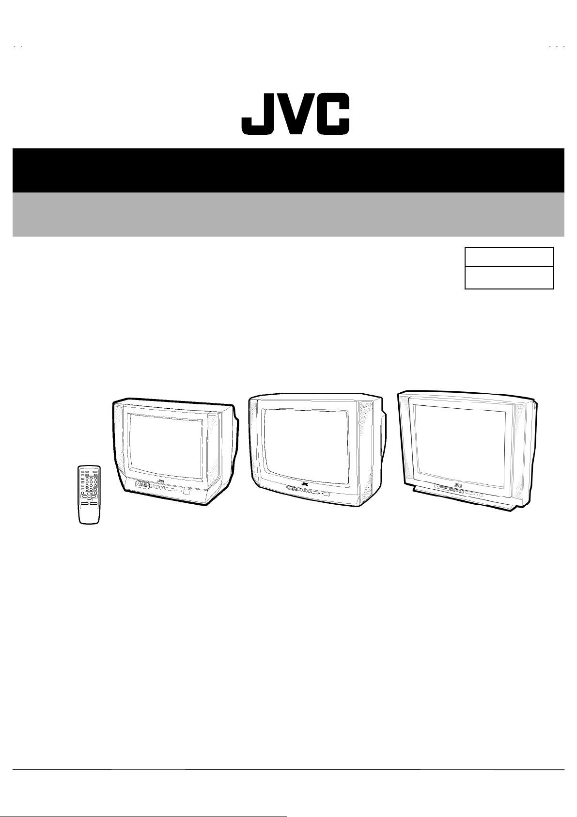
SERVICE MANUAL
COLOUR TELEVISION
AV-21D43
AV-20N43
AV-14F43
BASIC CHASSIS
[ RM-C368GY ]
[ AV-14F43
AV-21D43
AV-20N43
AV-14F43
/BK
]
[ AV-20N43
/BK
/BK
/BK
/BK
]
CG
[ AV-21D43
/BK
]
CONTENTS
SPECIFICATIONS ・・・・・・・・・・・・・・・・・・・・・・・・・・・・・・・・
!
SAFETY PRECAUTIONS ・・・・・・・・・・・・・・・・・・・・・・・・・・・・・・・・
!
FEATURES・・・・・・・・・・・・・・・・・・・・・・・・・・・・・・・・
!
FUNCTIONS ・・・・・・・・・・・・・・・・・・・・・・・・・・・・・・・・
!
MAIN DIFFERENCE LIST ・・・・・・・・・・・・・・・・・・・・・・・・・・・・・・・・
!
SPECIFIC SERVICE INSTRUCTIONS ・・・・・・・・・・・・・・・・・・・・・・・・・・・・・・・・
!
SERVICE ADJUSTMENTS ・・・・・・・・・・・・・・・・・・・・・・・・・・・・・・・・
!
PARTS LIST ・・・・・・・・・・・・・・・・・・・・・・・・・・・・・・・・
!
★ OPERATING INSTRUCTIONS
★ STANDARD CIRCUIT DIAGRAM ・・・・・・・・・・・・・・・・・・・・・・・・・・・・・・・・
1
・・・・・・・・・・・・・・・・・・・・・・・・・・・・・・・・・・・・・・・・・・・・・・・・・・・・・・・・・・・・・・・・
・・・・・・・・・・・・・・・・・・・・・・・・・・・・・・・・・・・・・・・・・・・・・・・・・・・・・・・・・・・・・・・・
・・・・・・・・・・・・・・・・・・・・・・・・・・・・・・・・・・・・・・・・・・・・・・・・・・・・・・・・・・・・・
・・・・・・・・・・・・・・・・・・・・・・・・・・・・・・・・・・・・・・・・・・・・・・・・・・・・・・・・・・・・・・・・
・・・・・・・・・・・・・・・・・・・・・・・・・・・・・・・・・・・・・・・・・・・・・・・・・・・・・・・
・・・・・・・・・・・・・・・・・・・・・・・・・・・・・・・・・・・・・・・・・・・・・・・・・・・・・・・・・・・・・・・・
・・・・・・・・・・・・・・・・・・・・・・・・・・・・・・・・・・・
・・・・・・・・・・・・・・・・・・・・・・・・・・・・・・・・・・・・・・・・・・・・・・・・・・・・・・・・・・・・・・・・
・・・・・・・・・・・・・・・・・・・・・・・・・・・・・・・・・・・・・・・・・・・・・・・・・・・・・・・・・・・・・・・・
・・・・・・・・・・・・・・・・・・・・・・・・・・・・・・・・・・・・・・・・・・・・・・・・・・・・・・・・・・・・・・・・
・・・・・・・・・・・・・・・・・・・・・・・・・・・・・・・・・・・・・・・・・・・・・・・・・・・・・・・
・・・・・・・・・・・・・・・・・・・・・・・・・・・・・・・・・・・・・・・・・・・・・・・・・・・・・・・・・・・・・・・・
・・・・・・・・・・・・・・・・・・・・・・・・・・・・・・・・・・・・・・・・・・・・・
・・・・・・・・・・・・・・・・・・・・・・・・・・・・・・・・・・・・・・・・・・・・・・・・・・・・・・・・・・・・・・・・
・・・・・・・・・・・・・・・・・・・・・・・・・・・・・・・・・・・・・・・・・・・・・・・・・・・・・
・・・・・・・・・・・・・・・・・・・・・・・・・・・・・・・・・・・・・・・・・・・・・・・・・・・・・・・・・・・・・・・・
・・・・・・・・・・・・・・・・・・・・・・・・・・・・・・・・・・・・・・・・・・・・・・・・・・・・・・・・・・・・・・・・
・・・・・・・・・・・・・・・・・・・・・・・・・・・・・・・・・・・・・・・・・・・・・・・・・・・・・・・・・・・・・・・・
・・・・・・・・・・・・・・・・・・・・・・・・・・・・・・・・・・・・・・・・・・・・・・・・
・・・・・・・・・・・・・・・・・・・・・・・・・・・・・・・・・・・・・・・・・・・・・・・・・・・・・・・・・・・・・・・・
COPYRIGHT © 2002 VICTOR COMPANY OF JAPAN, LTD.
・・・・・・・・・・・・・・・・・・・・・・・・・・・・・ 2
・・・・・・・・・・・・・・・・・・・・・・・・・・・・・・・・・・・・・・・・・・・・・・・・・・・・・・・・・・
・・・・・・・・・・・・・・・・・・・・・・・ 3
・・・・・・・・・・・・・・・・・・・・・・・・・・・・・・・・・・・・・・・・・・・・・・
・・・・・・・・・・・・・・・・・・・・・・・・・・・・・・・・・・
・・・・・・・・・・・・・・・・・・・・・・・・・・・・・・・・・・・・・・・・・・・・・・・・・・・・・・・・・・・・・・・・
・・・・・・・・・・・・・・・・・・・・・・・ 7
・・・・・・・・・・・・・・・・・・・・・・・・・・・・・・・・・・・・・・・・・・・・・・
・・・・・・・・・・・・・・・・・・・・・ 19
・・・・・・・・・・・・・・・・・・・・・・・・・・・・・・・・・・・・・・・・・・
・・・・・・・・・・・・・・・・・・・・・・・・・・・・・・・・・・・・ 37
・・・・・・・・・・・・・・・・・・・・・・・・・・・・・・・・・・・・・・・・・・・・・・・・・・・・・・・・・・・・・・・・
・・・ 4
・・・・・・
・・ 5
・・・・
・・・・・・・・・・・・・ 8
・・・・・・・・・・・・・・・・・・・・・・・・・・
・・・・・・・・・・・・・・・・ 2-1
・・・・・・・・・・・・・・・・・・・・・・・・・・・・・・・・
No. 52036
Aug. 2002
Page 2
A
V-21D43
A
A
V-20N43
V-14F43
SPECIFICATIONS
ITEM
Dimensions(W×H×D)
Mass (Net)
TV RF System B/G,I, D/K,
RF Mode
Colour System
Picture Tube
High Voltage
Receiving
Intermediate
Frequency
Colour Sub Carrier Frequency
VIDEO Mode
VHF (VL) 46.25MHz~168.25MHz
VHF (VH) 175.25MHz~463.25MHz
UHF 471.25MHz~863.25MHz
CATV
VIF Carrier 38.0MHz
SIF Carrier
598mm×468mm×478mm
21kg
PAL / SECAM
PAL / SECAM
NTSC3.58 / NTSC4.43
Visible size: 51cm measured
diagonally
26.5kV±1.5kV(at zero beam
current)
Cable TVs of Mid (X-Z, S1-S10)
Super (S11-S20) & Hyper (S21S41) bands receivable
32.5MHz(5.5MHz)
31.5MHz (6.5MHz)
32.0MHz (6.0MHz)
PAL (4.43MHz),
SECAM(4.40625MHz/4.25MHz)
NTSC (3.58MHz / 4.43MHz)
CONTENT
AV-21D43/BK AV-20N43/BK AV-14F43/BK
619mm×458mm×488mm 462mm×340.5mm×375mm
19kg 10kg
Visible size: 48cm measured
diagonally
Visible size: 34c m measured
diagonally
22.5kV±1.5kV(at zero beam
current)
Power Input
Power Consumption 105W (Max) / 68W (Avg) 90W (Max) / 60W (Avg) 70W (Max) / 47W (Avg)
Speaker 5cm×12 cm, Oval type×25cm×9 c m, Oval type×2
Audio Output A2 / Billingual,5W (monaural) A2 / Billingual,3W (monaural)
Aerial Input Terminal 75Ω Unbalanced
Input Video 1V(p-p), 75Ω (Front / Rear)
Output Video 1V(p-p), 75Ω
Headphone jack
Remote Control Unit
Rating V oltage AC110~240V, 50 / 60Hz
Operating Voltage AC90~260V, 50 / 60Hz
500mV(r ms) (-4dBs), High
Audio
Audio
impedance,
RCA×2 (Front / Rear)
500mV(r ms) (-4dBs), Low
impedance,
RCA×1
3.5 mm mini jack
RM-C368GY
(Battery size : AA / R06 / UM-3×
2)
Design and specifications are subject to change without notice.
2
No. 52036
Page 3
A
A
A
SAFETY PRECAUTIONS
V-21D43
V-20N43
V-14F43
1. The design of this product contains special hardware, many
circuits and components specially for safety purposes. For
continued protection, no changes should be made to the original
design unless authorized in writing by the manufacturer.
Replacement parts must be identic al to those used in the original
circuits. Service should be performed by qualified personnel
only.
2. Alterations of the design or circuitry of the products should not be
made. Any design alterations or additions will void the
manufacturer's warranty and will further relieve the manufacturer
of responsibility for personal injury or property damage resulting
theref rom.
3. Many electric al and mechanical parts in the products have
special safety-related characteristics. These characteristics are
often not evident from visual inspection nor can the protection
afforded by them necessarily be obtained by using replacement
components rated for higher voltage, wattage, etc. Replacement
parts which have these special safety characteristics are
identified in the parts list of Service manual. Electrical
components having such features are identified by shading
on the schematics and by (!!!!) on the parts list in Service
manual. The use of a subst itute replacement which does not
have the s ame safety characteristics as the recommended
replacement part shown in the parts list of Service manual may
cause shock, fire, or other hazards.
4. Don't short between the LIVE side ground and ISOLATED
(NEUTRAL) side ground or EARTH side ground when
repairing.
Some model's power circuit is partly different in the GND. The
differenc e of the GND is shown by the LIVE : (") side GND, the
ISOLATED(NEUTRAL) : (#) side GND and EARTH : ($) side
GND. Don't short between the LIVE side GND and
ISOLATED(NEUTRAL) side GND or EARTH side GND and
never meas ure with a measuring apparatus (oscilloscope etc.)
the LIVE side GND and ISOLATED(NEUTRAL) side GND or
EARTH side GND at the same time.
If above note will not be kept, a fuse or any parts will be broken.
5. If any repair has been made to the chassis, it is recommended
that the B1 setting should be checked or adjusted (See
ADJUSTMENT OF B1 POWER SUPPLY).
6. The high voltage applied to the picture tube must conform with
that specified in Service manual. Excessive high voltage can
cause an incr ease in X-Ray emission, arcing and possible
component damage, therefore operation under excessive high
voltage conditions should be kept to a minimum, or should be
prevented. If severe arcing occurs, remove the AC power
immediately and det ermine the caus e by visual inspection
(incorrect installation, cr acked or melted high voltage harness,
poor soldering, etc.). To maintain the proper minimum level of
soft X-Ray emission, components in the high voltage circuitry
including the picture tube must be the exact replacements or
alternatives approved by the manuf actur er of the complete
product.
7. Do not check high voltage by drawing an arc. Use a high voltage
meter or a high voltage probe with a VTVM. Discharge the
picture tube before attempting meter connection, by connecting
a clip lead to the ground frame and connecting the other end of
the lead through a 10kΩ 2W resistor to the anode button.
8. When service is requir ed, obser ve the original lead dress. Extra
precaution should be given to assure correct lead dress in the
high voltage circuit area. W here a short circuit has occurred,
those components that indicat e evidenc e of overheating should
be replaced. Always us e the manufacturer's replacement
components.
9. Isolation Check
(Safety for Electrical Shock Hazard)
After re-assembling the product, always perf orm an isolation
check on the exposed metal parts of the cabinet (antenna
terminals, video/audio input and output terminals, Control knobs,
metal c abinet, screwheads, earphone jack, c ontrol shafts, etc.)
to be sure the product is safe to operat e without danger of
electr ical shoc k.
(1) Dielectr ic Strength Test
The isolation between the AC primary circuit and all metal parts
exposed to the user, particularly any expos ed metal part having a
return path to the chass is should withstand a voltage of 3000V
AC (r.m.s.) for a period of one second.
(. . . . Withstand a voltage of 1100V AC (r.m.s.) to an applianc e
rated up to 120V, and 3000V AC (r.m.s.) to an appliance rated
200V or more, for a period of one second.)
This method of test requires a test equipment not generally found
in the s ervice trade.
(2) Leakage Current Check
Plug the AC line cord directly into the AC outlet (do not use a line
isolation transformer dur ing this check.). Using a "Leakage
Current T ester", measure the leakage current from each exposed
metal part of the cabinet, particularly any exposed metal part
having a return path to the chassis, to a known good earth
ground (water pipe, etc.). Any leakage c urrent must not exceed
0.5mA AC (r.m.s.).
However, in tr opical area, this must not exceed 0.2mA AC
(r.m.s.).
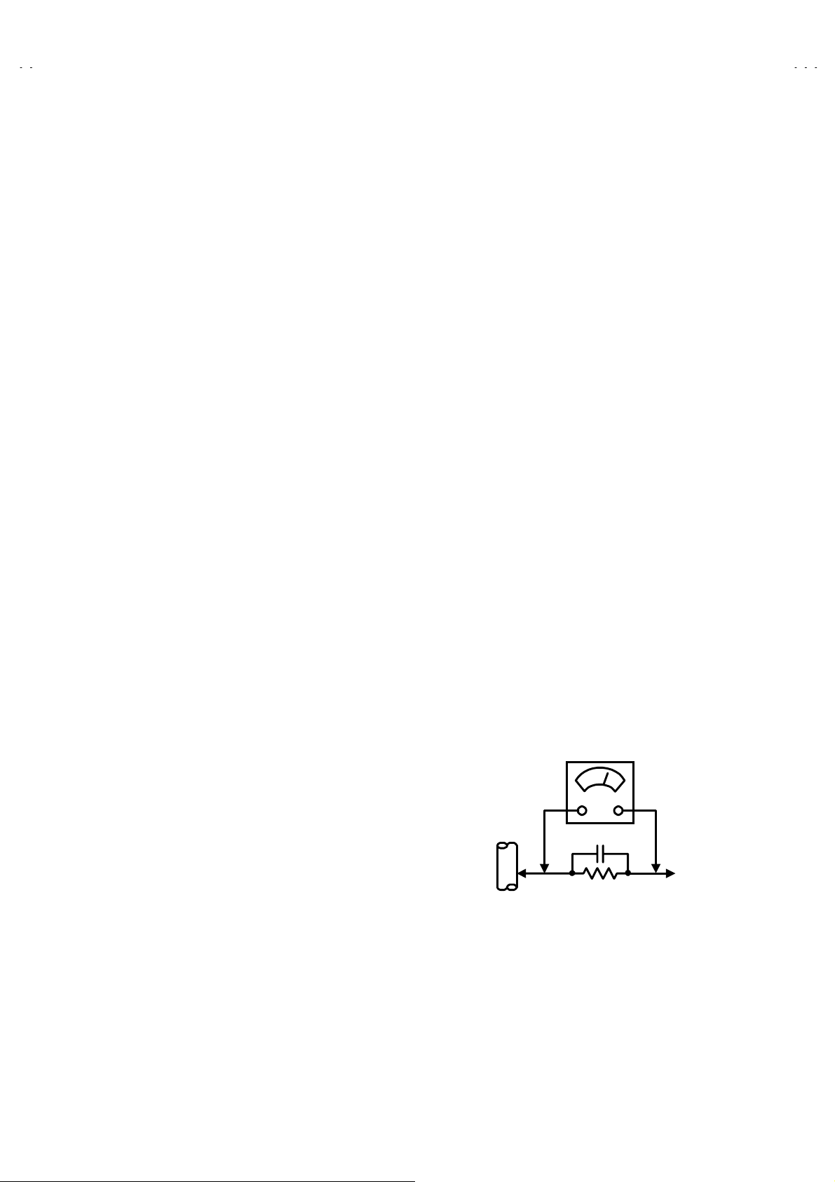
"""" Alternate Check Method
Plug the AC line cord directly into the AC outlet (do not use a line
isolation transformer during this check.). Use an AC volt meter
having 1000 ohms per volt or more sensitivity in the following
manner. Connect a 1500Ω 10W resistor paralleled by a 0.15µF
AC-type capacitor between an expos ed metal part and a known
good earth ground (water pipe, etc.). Measure the AC voltage
across the resistor with the AC voltmeter. Move the resistor
connection to each exposed metal part, particularly any exposed
metal part having a return path to the chassis, and measure the
AC voltage across the resist or. Now, reverse the plug in the AC
outlet and repeat each measurement. Any voltage meas ured
must not exceed 0.75V AC (r.m.s.). This corresponds to 0.5mA
AC (r.m.s.).
However, in tr opical area, this must not exc eed 0.3V AC (r.m.s.).
This corresponds to 0.2mA AC (r.m.s.).
AC VOLTMETER
(HAVING 1000 Ω/V,
OR MORE SENSITIVITY)
0.15μF AC-TYPE
PLACE THIS PROBE
1500 Ω 10W
GOOD EARTH GROUND
ON EACH EXPOSED
METAL PART
No.52036
3
Page 4
A
V-21D43
A
A
V-20N43
V-14F43
FEATURES
" New chassis design enables use of an inter active on-screen control.
" Wide range voltage (rating voltage :110V~240V / operating voltage : 90V~260V) AC power input.
" With AUDIO / VIDEO INPUT & OUTPUT terminal.
" MUTING button can reduce the audio level to zero instantly.
" Functional remote control to operate TV set (for channel s elect, volume c ontrol, power ON/OFF, etc.) from a distanc e.
2
C bus control utilizes single chip ICs for IF, V/C, DEF. VSM PRESET, PRESET & SETUP TOUR.
" I
" By means of AUTO PROGRAM, the TV stations can be selected automatically and the TV channels can also be r earranged automatic ally.
" Built-in AI ECO (ECONOMY, ECOLOGY) sensor.
In accordance with the brightness in a room, the brightness and / of contrast of the picture can be adjusted aut omatically to make the
optimum picture which is easy on the eye.
" Built – in ON TIMER, RETURN + & CHILD LOCK.
" Built–in PICTURE BOOSTER circuit newly, to amplify the broadcasting wave in the area where wave is weak.
SYSTEM BLOCK DIAGRAM
"
IC702
MEMORY
SCL2/SDA2
IC701
MICRO
COMPUTER
IC301
VIDEO/CHROMA
DECORDER
SCL1/SDA1
TU001
TUNER
4
No. 52036
Page 5
A
A
A
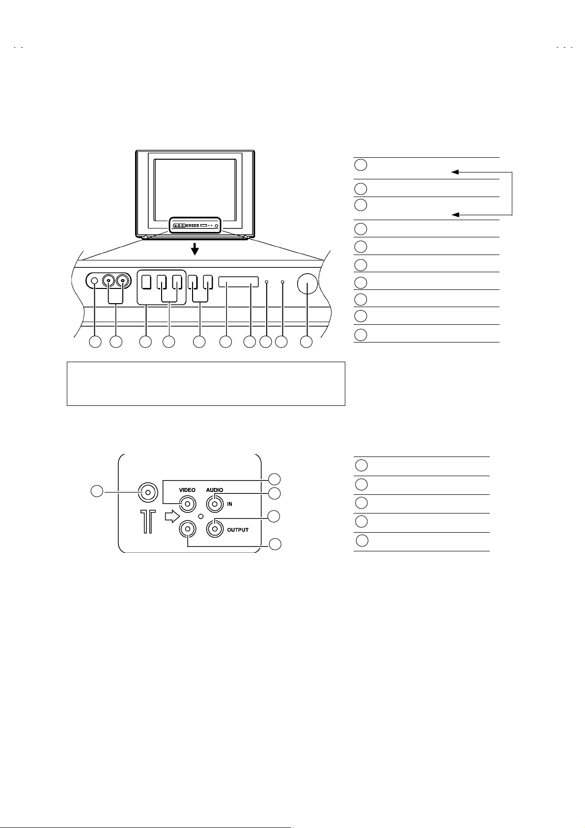
FUNCTIONS
■ FRONT PANEL
V-21D43
V-20N43
V-14F43
[AV-21D43/BK]
10 9 1 2 3 4 5 6 7 8
This illustration shows the AV- 21D43
20N43
/BK
and AV-14F43
models for the arrangements of buttons, lamps, etc. on the front panel.
/BK
is different, this illustration is applicable to both
/BK
. Although the design of the AV-
■ REAR TERMINAL
MENU butt ons
1
(Replacement of IC301)
CHANNEL -/+ buttons
2
VOLUME -/+ buttons
3
(Replacement of IC301)
AI ECO sensor
4
REMOTE CONTROL sensor
5
ON TIMER lamp
6
POWER lamp
7
MAIN POWER button
8
A/V INPUT terminal
9
HEADPHONE jack
10
ANT Terminal
1
2
1
3
4
5
VIDEO INPUT Terminal
2
AUDIO INPUT Terminal
3
4
AUDIO OUTPUT Terminal
VIDEO OUTPUT Terminal
5
No. 52036
5
Page 6
A
V-21D43
A
A
V-20N43
V-14F43
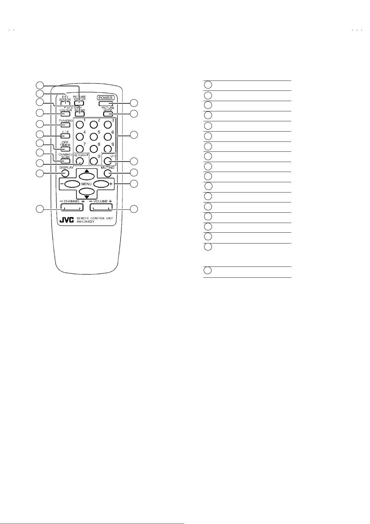
■ REMOTE CONTROL UNIT
1
2
3
4
5
6
7
8
9
10
11
12
13
14
15
16
17
18
PICTURE BOOSTER key
1
ECO SENSOR key
2
SOUND SYSTEM key
3
4
COLOUR SYSTEM key
TV/VIDEO key
5
Ⅰ/Ⅱ Key
6
OFF TIMER key
7
CHANNEL SCAN key
8
RETURN+key
9
DISPLAY key
10
11
CHANNEL-/+ key
12
POWER key
PICTURE MODE key
13
14
Number (CH.) key
15
-/--key
16
MUTING key
MENU key
17
MENU ▲/▼ key
MENU -/+ key
18
VOLUME-/+ key
6
No. 52036
Page 7
A
A
A
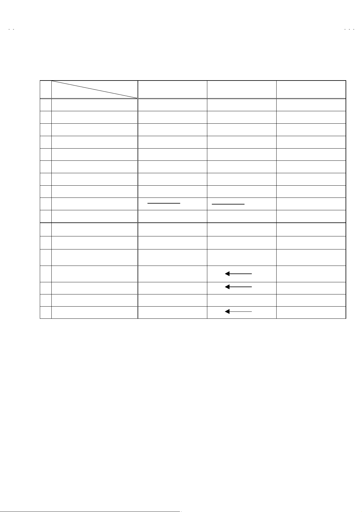
MAIN DIFFERENCE LIST
Model Name
!
Part Name (Item)
MAIN PWB SCG-1435A SCG-1434A SCG-1433A
! FRONT CABINET LC11129- 021A-H LC10438- 032A-H LC10831- 030A-H
! REAR COVER GG10130-005A-H LC10448- 002B-H CM12961-D01-VH
SPEAKER QAS0086-001 CEBSS12D-07KJ2 QAS0054-001
!
PICTURE TUBE A51LMV10X A48LSD095X A34AGT13X
! DEF YOKE CE20336-00A QQD0034-001 QQD0046-001
! DEG COIL QQW0006-001 QQW0061-001 QQW0093-001
! F. B. TRANSF QQH0069-001 QQH0073-001 QQH0072-001
!
PWB STOPPER CM48144-002-H
AV-21D43
/BK
AV-20N43
/BK
AV-14F43
V-21D43
V-20N43
V-14F43
/BK
PACKING CASE GG10056-065A-H GG10056-064A-H GG10056-066B-H
Dimensions (W ×H×D) 598mm×468mm×478mm 619mm×458mm×488mm 462mm×340.5mm×375mm
Mass (Net) 21kg 19kg 10kg
Picture T ube
High Voltage
Speaker
Power C onsumption 105W (Max) / 68W (Avg) 90W (Max) / 60W (Avg) 70W (Max) / 47W (Avg)
Audio Output A2 / Billingual,5W (monaural) A2 / Billingual,3W (monaural)
Visible size: 51cm measured
diagonally
26.5kV±1.5kV(at zero beam
current)
5cm×12 cm, Oval type×25cm×9 c m, Oval type×2
Visible size: 48cm measured
diagonally
Visible size: 34cm measured
diagonally
22.5kV±1.5kV(at zero beam
current)
No. 52036
7
Page 8

A
V-21D43
A
A
V-20N43
V-14F43
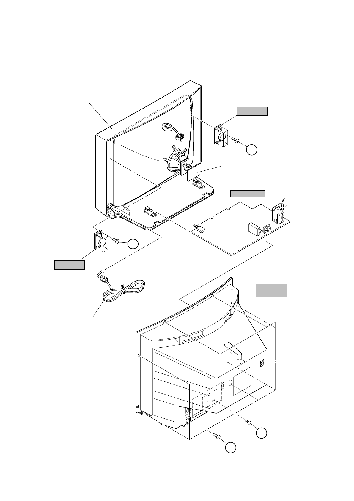
SPECIFIC SERVICE INSTRUCTIONS
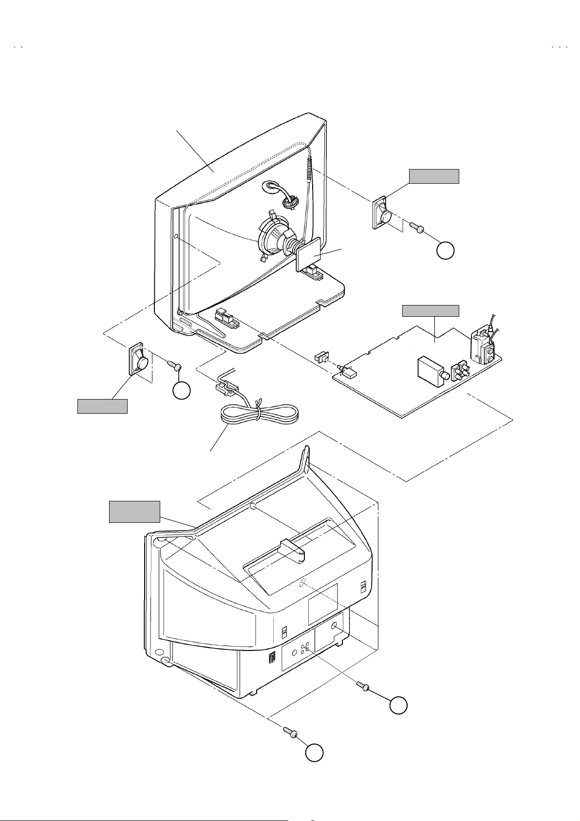
DISASSEMBLY PROCEDURE
REMOVING THE REAR COVER
1. Unplug the power plug.
screws marked
2. As shown in figure, remove the
screw marked
3. Withdr aw the rear cover toward you.
""""
.
7
REMOVING THE MAIN PW BOARD
" After removing the rear cover.
1. Slightly raise the both sides of the MAIN PW BOARD by hand.
2. Withdr aw the MAIN PW BOARD backward.
(If necessary, take off the wire clamp, connectors etc.)
REMOVING THE SPEAKER
" After removing the rear cover.
screws marked
1. As shown in figure, remove the
2. Follow the same steps when r emoving the other hand speak er.
4
####
!!!!
.
and a
CHECKING THE MAIN PW BOARD
1. To check the back side of the PW Board.
1) Pull out the MAIN PW Board. (Refer to REMOVING THE MAIN
PW Boar d)
2) Erect the PW Boar d vertically so that you can easily check the
back side of the PW Board.
[CAUTION]
" When erecting the PW Board, be careful so that there will be no
contac ting with oth er PW Boar d.
" Before turning on power, make sure that the CRT earth wire and
other connector are properly connected.
WIRE CLAMPING AND CABLE TYING
1. Be sure t o clamp the wire.
2. Never remove the cable tie used for tying t he wires together.
Should it be inadvertently removed, be sure to tie the wires with a
new cable tie.
8
No. 52036
Page 9
A
A
A
FRONT CABI.
SPEAKER
CRT SOCKET
PWB
MAIN PWB
V-21D43
V-20N43
V-14F43
(××××4)
C
SPEAKER
(××××4)
C
REAR
COVER
POWER
CORD
(××××1)
B
(××××7)
A
No. 52036
9
Page 10

A
V-21D43
A
A
V-20N43
V-14F43
DISASSEMBLY PROCEDURE
REMOVING THE REAR COVER
1. Unplug the power plug.
2. As shown in figure, remove the
screw marked
3. Withdr aw the rear cover toward you.
""""
.
screws marked
6
REMOVING THE MAIN PW BOARD
" After removing the rear cover.
1. Slightly raise the both sides of the MAIN PW BOARD by hand.
2. Withdr aw the MAIN PW BOARD backward.
(If necessary, take off the wire clamp, connectors etc.)
REMOVING THE SPEAKER
" After removing the rear cover.
screws marked
1. As shown in figure, remove the
2. Follow the same steps when r emoving the other hand speak er.
2
####
!!!!
.
and a
CHECKING THE MAIN PW BOARD
1. To check the back side of the PW Board.
1) Pull out the MAIN PW Board. (Refer to REMOVING THE MAIN
PW Boar d)
2) Erect the PW Boar d vertically so that you can easily check the
back side of the PW Board.
[CAUTION]
" When erecting the PW Board, be careful so that there will be no
contac ting with oth er PW Boar d.
" Before turning on power, make sure that the CRT earth wire and
other connector are properly connected.
WIRE CLAMPING AND CABLE TYING
1. Be sure t o clamp the wire.
2. Never remove the cable tie used for tying t he wires together.
Should it be inadvertently removed, be sure to tie the wires with a
new cable tie.
10
No. 52036
Page 11
A
A
A
FRONT CABI.
V-21D43
V-20N43
V-14F43
SPEAKER
SPEAKER
REAR
COVER
C
(××××2)
POWER
CORD
CRT SOCKET
PWB
C
MAIN PWB
(××××2)
B
(××××1)
(××××6)
A
No. 52036
11
Page 12

A
V-21D43
A
A
V-20N43
V-14F43
DISASSEMBLY PROCEDURE
REMOVING THE REAR COVER
1. Unplug the power plug.
screws marked
2. As shown in figure, remove the
screw marked
3. Withdr aw the rear cover toward you.
"""",####
.
4
REMOVING THE MAIN PW BOARD
" After removing the rear cover.
1. Slightly raise the both sides of the MAIN PW BOARD by hand
and remove the PWB stopper marked
2. Withdr aw the MAIN PW BOARD backward.
(If necessary, take off the wire clamp, connectors etc.)
from the front cabinet.
$$$$
REMOVING THE SPEAKER
" After removing the rear cover.
screws marked
1. As shown in figure, remove the
2. Follow the same steps when r emoving the other hand speak er.
2
%%%%
!!!!
.
and a
CHECKING THE MAIN PW BOARD
1. To check the back side of the PW Board.
1) Pull out the MAIN PW Board. (Refer to REMOVING THE MAIN
PW Boar d)
2) Erect the PW Boar d vertically so that you can easily check the
back side of the PW Board.
[CAUTION]
" When erecting the PW Board, be careful so that there will be no
contac ting with oth er PW Boar d.
" Before turning on power, make sure that the CRT earth wire and
other connector are properly connected.
WIRE CLAMPING AND CABLE TYING
1. Be sure t o clamp the wire.
2. Never remove the cable tie used for tying t he wires together.
Should it be inadvertently removed, be sure to tie the wires with a
new cable tie.
12
No. 52036
Page 13

A
A
A
FRONT CABI.
CRT SOCKET
PWB
MAIN PWB
SPEAKER
E
V-21D43
V-20N43
V-14F43
(××××2)
REAR
COVER
POWER
CORD
PWB STOPPER
D
(××××1)
B
(××××1)
C
A
(××××4)
No. 52036
13
Page 14

A
V-21D43
A
A
V-20N43
V-14F43
REPLACEMENT OF MEMORY ICs
1. MEMORY ICs
This model uses memory ICs. This memory IC data are for proper operation of the video and deflection circ uits.
When replacing memory ICs, be sure to use ICs written with the initial values of data.
2. PROCEDURE FOR REPLACING MEMORY ICs
(1) Power off
Switch the power off and disconnect the power plug from the wall outlet.
(2) Replace ICs
Be sure to use memory ICs written with the initial data values.
(3) Power on
Connect the power plug into the wall outlet and switch the power on.
(4) Check and set SYSTEM CONSTANT SET
・・・・It must not adjust without adjustment signals.
1) Press the DISPLAY key and the PICTURE MODE key of the REMOTE
CONTROL UNIT simultaneously.
2) The SERVICE MENU screen of Fig. 1 will be displayed.
3) While the SERVICE MENU is displayed, again press the DISPLAY key and
PICTURE MODE key simultaneously, and the S YSTEM CONSTANT SET
screen of Fig. 2 will be displayed.
4) Check the setting values of the SYSTEM CON STANT SET of T able 1 If the
value is different, select the s etting item with the MENU ▼/▲key, and set
the correct value with the MENU - / + key.
5) Press the DI SPLAY key twice, and return to the normal screen.
(5) Receive channel of setting
Refer to the OPERATING INSTRUCTIONS and set the r eceive channels
(channels preset) as described
(6) User Setting
Check the user setting value of Table 2, and if setting value is different, set
the correct value.
For setting, refer to the OPERATING INSTRUCTIONS.
(7) Setting of SERVICE MENU
Verify the setting items of the SERVICE MENU, and reset where necessar y.
For setting, refer to the SERVICE ADJUSTMENTS.
KEY ASSIGNMENT OF REMOTE CONTROL UNIT
1.IF 2.V/C
3.DEF 4.VSM PRESET
5.PRESET
6.SETUP TOUR OFF
1-6 SELECT DISP : EXIT
******
***********
************
SYSTEM CONSTANT SET 1
: SELECT
- / + : OPERATE DISP : EXIT
SYSTEM CONSTANT SET 2
: SEL - / + : OPE DISP : EXIT
SERVICE MENU
***** **
**.****
** **
****
********
** ***
** ***** ***
**********
*** ** **
*** ** **** ***
*** ** ***** ** **
Fig.1
SYSTEM CONSTANT-ⅠⅠⅠⅠ
COLOUR : TRIPLE
BILINGUAL : YES
TUNER : MU
ECO SENSOR : YES
LANGUAGE : E / T
/
SYSTEM CONSTANT-ⅡⅡⅡⅡ
B/B SOUND : OFF
LOCK : 180
COLOUR AUTO : NO
QSS : MINT
ALC : NO
TEXT RATE : 20
/
SYSTEM CONSTANT-ⅢⅢⅢⅢ
PICTURE
MODE ke y
NUMBERS
SYSTEM CONSTANT SET 3
AMP TUNER : YES
VNR : NO
TEXT TABLE : CYL
VOLUM PWM : ENG
key
: SEL - / + : OPE DISP : EXIT
/
DISPLAY
key
MENU
MENU
▼/▲ key
Fig.2
-/+key
14
No. 52036
Page 15

A
A
A
SETTING OF SYSTEM CONSTANT SET
A
Setting item Setting contents Setting value
V-21D43
V-20N43
V-14F43
COLOUR
BILINGUAL
TUNER
AI ECO SENSOR
LANGUAGE
B/B SOUND
LOCK
COLOUR AUTO
QSS
ALC
TEXT RATE
AMP TUNER
VNR
TEXT TABLE
VOLUM PWM
MULTI.
YES NO
MA
MU
YES NO
E
ON
YES 10 20
YES NO
MINT MQSS
YES NO
10 20 40 80
YES NO
YES NO
RA
POS
E/T
OFF
CYL
NEG
PALTRIPLE
230 240 250
~
TRIPLE
YES
MU
YES
E / T
OFF
180
NO
MINT
NO
20
YES
NO
CYL
ENG
Table 1
USER SETTING VALUES
Setting item Setting value Setting item Setting value
SUB POWER ON LANGUAGE THAI
CHANNEL POSITION 1 POSITION CHANNEL PRESET Refer to OPERATING INSTRUCTION
VOLUME About 10 AI ECO SENSOR OFF
TV/VIDEO
ON SCREEN DISPLAY
COLOUR SYSTEM PAL ON TIMER PR1 0:00
SOUND SYSTEM B / G BLUE BACK OFF
OFF TIMER OFF OSD.Shows 00 CHILD LOCK OFF
PICTURE MODE (VSM) BRIGHT SETUP TOUR ON
BILINGUAL MODE
TV VNR OFF (AV-14F43
POSITION INDICATION AUTO SHUTOFF OFF
Ⅰ(Ⅰ/Ⅱ)
PICTURE BOOSTER OFF
Table 2
/BK
Only)
No. 52036
15
Page 16

A
V-21D43
A
A
V-20N43
V-14F43
INITIAL SETTING VALUE OF SERVICE MENU
1. Adjustment of the SERVICE MENU is made on the basis of the initial setting values ; however, the new setting values which
set the screen in its optimum condition may differ from the initial setting.
2. Do not change the initial Setting Values of the Setting (Adjustment) items not listed In “ADJUSTMENT”.
2. V/C
Colour system
Setting item
PAL SECAM NTSC 3.58 NTSC 4.43
RED
GREEN1. CUT OFF
-50
BLUE
2. DRIVE
RED
BLUE
+ 0
3. BRIGHT + 0
4. CONT. + 0
5. COLOUR + 0
TV
6. TINT
7. SECAM BL ADJ.
8. SHARP
Do Not Adj.
9. AMP T. SHARP
Do Not Adj.
VIDEO
TV
VIDEO
AV-21D43/BK
AV-20N43
AV-14F43
/BK
/BK
AV-21D43/BK
AV-20N43
AV-14F43
/BK
/BK
AV-21D43/BK
AV-20N43
AV-14F43
AV-21D43
/BK
/BK
/BK
AV-20N43/BK
AV-14F43/BK
+ 0
- 7(Fixed)
- 15(Fixed)
+ 15(Fixed)
+ 5(Fixed)
- 12(Fixed)
- 14(Fixed)
Initial setting value
+ 0 + 0
+ 0
+ 0 - 2
+ 0
3. DEFLECTION
Initial setting value
Setting item
AV-21D43
AV-20N43
fv : 50Hz MODE fv : 60Hz MODE
/BK
/BK
AV-14F43/BK
AV-21D43/BK
AV-20N43
/BK
AV-14F43/BK
1. VER. POSITION - 1 + 0 - 3 - 3
2. HOR. POSITION + 3+ 1+ 3+ 4
3. VER. HEIG HT -35 - 20 + 1 - 2
4. VER. LINE ARIT Y +15 + 15 - 1 + 0
5. VER. SCURVE -32 - 32 + 0 + 0
6. HOR. VCO ADJUST Do Not Adj. + 0 + 0 + 0 + 0
4.VSM PRESET
VSM preset mode
VSM Setting item
BRIGHT STANDARD SOFT
1. TINT +15
2. COLOUR +15
3. BRIGHT +15
4. CONT. +30 +19 +14
5. SHARP +20 +15
16
No. 52036
Page 17

A
A
A
5. PRESET
The items in the following table, it is no requirement f or adjustment.
If values had changed by the miss operation, set the initial setting values in the following table.
Colour System Do Not Adjust
V-21D43
V-20N43
V-14F43
Setting item
1. C TRAP FIX 1 1 1 1
2. SHARP PEAK 0 0 0 0
3. ABL 1 1 1 1
4. GAMMA 0 0 0 0
TV 0 2 2 3
5. Y. DELAY TIME
VIDEO
6. BLACK EXP START
TV 1 1 0 0
7. C-BPF
VIDEO
8. CW / SCP 0 0 0 0
9. VIF DET LEVEL 0 0 0 0
11. IF AGC MIN 0 0 0 0
12. VIF AGC 0 0 0 0
13. VIF PMOD 0 0 0 0
19. VNR 15 15 15 15
PAL SECAM NTSC 3.58 NTSC 4.43
0 2 0 2
+3 +3 +3 +3
1 1 1 1
Initial setting value (Fixed value)
20. RGB LIM 1 1 1 1
21. RGB LIMIT LEVEL 2 2 2 2
23. TEXT H. POSITION -3 -3 -3 -3
24. READ DATA
Sound System Do Not Adjust
Setting i tem B/G I D/K M
10. SIF DET LEVEL +0 +0 +0 +0
14. SIF BPF BW ADJUST +0 +0 +0 +0
15. SIF TRAP FO ADJUST +0 +0 +0 +0
16. SIF TRAP FO ADJUST 2 +0 +0 +0 +0
17. SIF -TRAP 0 0 0 0
18. SIF -BPF 1 0 0 0
22. SIF SW 0 1 1 1
No. 52036
17
Page 18

A
V-21D43
A
A
V-20N43
V-14F43
REPLACEMENT OF IC301 (IF V/C DECODER)
" For the IC301(IF V/C DECODER) of this model, all data are written in the micro-computer. So, write the data in the micro-
computer (EP-R OM : memory IC) in accordance with the following procedures before starting adjustment.
PROC EDURES
(1) Turn the POW ER OFF.
(2) Replace the IC301 with a new one.
(3) While pressing MENU button and VOLUME -/+ button ON the FRONT CABINET simultaneously, turn the POWER ON. When the
POWER is turned ON, the data is written in the micro-computer (EP-ROM : memory IC) immediately.
LOCATIONS OF FRONT PANEL BUTTONS AND LAMPS
[AV-21D43/BK]
1 2 3 4 5 6 7 8
This illustration shows the AV- 21D43/BK. Although the design of the AV-20N43/BK
and AV-14F43
arrangements of buttons, lamps, etc. on the front panel.
/BK
is different, this illustration is applicable to both models for the
MENU buttons
1
2
CHANNEL -/+ buttons
(MENU -/+ buttons)
VOLUME -/+ buttons
3
(MENU -/+ buttons)
AI ECO sensor
4
REMOTE CONTROL sensor
5
ON TIMER lamp
6
POWER lamp
7
MAIN POW ER button
8
18
No. 52036
Page 19

A
A
A
SERVICE ADJUSTMENTS
BEFORE STARTING SERVICE ADJUSTMENT
1. There are 2 way of adjusting this TV: One is with t he
REMOTE CONTROL UNIT and the other is the conventional
method using adjustment parts and components.
2. The adjustment with the REM OTE C ONTROL UNIT is made
on the basis of the initial setting values. The setting values
which adjust the screen t o its optimum condition may differ
from the initial setting values.
3. Make sure that connection is correctly made to AC power
source.
4. Turn on t he power of the set and equipment before use, and
start the adjustment procedures after waiting at least 30 minutes.
5. Unless otherwise specified, prepare the most suitable reception
or input signal for adjustment.
6. Never touch any adjustment parts, which are not specified
in the list for this adjustment VRs, transforms, condensers,
etc.
7. Preparation for adjustment
Unless otherwise specified in the adjustment instructions, pr eset
the following functions with the REMOTE CONTROL UNIT.
User mode position
PICTURE MODE (VSM) BRIGHT
VNR OFF (AV-14F43
TINT / COLOUR / BRIGHT
CONT. / SHARP
SETUP TOUR ON
OFF TIMER OFF
AI ECO SENSOR OFF
AUTO SHUT OFF OFF
PICTURE BOOSTER OFF
CENTER
/BK
V-21D43
V-20N43
V-14F43
Only)
MEASURING INSTRUMENT AND FIXTURES
1. DC voltmeter (or digital voltmeter)
2. Oscill oscope
3. Signal generator (Pattern generator) [PAL / SECAM / NTSC]
4. Remote contr ol unit
ADJUSTMENT ITEMS
Adjustment item Adjustment item
B1 POWER SUPPLY
FOCUS adjustment VSM PRESET setting
IF circuit adjustment
V/C (Video / Chroma) circuit adjustment
DEFLECTION circuit adjustment
PURITY/ CONVERGENCE adjustment
No. 52036
19
Page 20

A
V-21D43
A
A
V-20N43
V-14F43
BASIC OPERATION OF SERVICE MENU
" The adjustment using SERVICE MENU
The following adjustment items use the SERVICE MENU in the series of the adjustment. The adjustments are made on the basis of the
initial s etting values. The adjustment values which adjust the screen to the optimum c ondition can be different from the initial setting values.
With the SERVICE MENU, various settings can be made, and they are broadly classified in the following items of settings.
1.IF ・・・・・・・・・・・・・・・・・・・・・・・ Adjustment of the IF circuits.
2.V/C ・・・・・・・・・・・・・・・・・・・・・・ Adjustment of the VIDEO/CHROMA circuit.
3.DEF ・・・・・・・・・・・・・・・・・・・・・ Adjustment of the DEFLECTION circuit.
4.VSM PRESET ・・・・・・・・・・・・ Adjustment of the initial setting values of VSM condition as STANDARD, SOFT and BRIGHT.
(VSM : Video Status Memory)
5.PRESET ・・・・・・・・・・・・・・・・・ Adjustment of the RF circuit [Do not adjust].
6.SETUP TOUR OFF ・・・・・・・・ It should be able to select mode (LANGUAGE and AUTO CH PRESET).
[Should be OFF].
" Key operation of the SERVICE MENU
[Enter to SERVICE MENU]
Press the DISPLAY key and the PICTURE MODE key of the REMOTE CONTROL
UNIT simultaneously. Then enter the SERVICE MENU mode as shown in Fig.1.
[Exit from SERVICE MENU]
When complete the adjustment work, press the DISPLAY key to return to the
SERVICE MENU.
And then press the DISPLAY key again, return to the normal screen.
[Select from SER VICE M ENU]
In SERVICE MENU, press the number (1~6) key of the remote control unit, to select
any of the adjustment items.
The colours whic h selected item characters are changed.
SERVICE MENU
KEY ASSIGNMENT OF REMOTE CONTROL UNIT
SERVICE MENU
1.IF 2.V/C
3.DEF 4.VSM PRESET
5.PRESET
6.SETUP TOUR OFF
1-6 SELECT DISP : EXIT
******
***********
***** **
************
**********
*** ** **
*** ** **** ***
*** ** ***** ** **
**.***
****
** ***
** ***** ***
***
******
Fig.1
PICTURE
MODE ke y
NUMBERS
key
DISPLAY key
MENU
MENU
▼/▲ key
-/+key
20
No. 52036
Page 21

A
A
A
[Method of setting]
1. IF
[1. VCO]
① 1 Key ・・・・・・・・・・・・・・・・・・・・・・・・・ Select 1.IF.
② 1 Key ・・・・・・・・・・・・・・・・・・・・・・・・・ Select 1.VCO
③ T he VCO (CW ) screen will be displayed a allow mark when the AFC voltage is at a certain level.
④ DISPLAY Key・・・・・・・・・・・・・・・・・・ As you press this key twice, you will return to the SERVICE MENU.
[2. DELAY POINT]
① 1 Key・・・・・・・・・・・・・・・・・・・・・・・・・ Select 1.IF.
② 2 Key・・・・・・・・・・・・・・・・・・・・・・・・・ Select 2.DELAY POINT.
③ MENU -/+ Key ・・・・・・・・・・・・・・・・・ Set (adjust) the setting values of the setting it ems.
④ DISPLAY Key・・・・・・・・・・・・・・・・・・ When this is pressed twice, you will return to the SERVICE MENU.
2.V/C, 3.DEF and 4.VSM PRESET
① 2~4Key ・・・・・・・・・・・・・・・・・・・・・・・ Select one from 2. V/C, 3. DEF and 4. VSM PRESET.
② MENU ▼/▲ Key ・・・・・・・・・・・・・・ Select setting items.
③ MENU -/+ Key ・・・・・・・・・・・・・・・・・ Adjust the v al ues of the items .
④ DISPLAY Key・・・・・・・・・・・・・・・・・・ When this is pressed, return to the SERVICE MENU.
V-21D43
V-20N43
V-14F43
6.SETUP TOUR
① By pressing the 6 key, you can change the ON or OFF ( should be OFF).
(Should be OFF)
%・ If it is ON, then you turn the TV power off, when you are turn the TV power on again.
The JVC’s logo will be shown about 15 seconds automatically.
② MENU -/+ Key ・・・・・・・・・・・・・・・・・ Select Language.
③ MENU ▼ Key ・・・・・・・・・・・・・・・・・ Auto Search.
No. 52036
21
Page 22

A
V-21D43
A
A
V-20N43
V-14F43
SERVICE MENU FLOW CHART
SERVICE MENU
SERVICE MENU
1.IF 2.V/C
3.DEF 4.VSM PRESET
5.PRESET
6.SETUP TOUR OFF
1-6 SELECT DISP : EXIT
******
***********
***** **
************
**.****
**********
** **
*** ** **
*** ** **** ***
*** ** ***** ** **
** ***
** ***** ***
6.SETUP TOUR
ON /
(By pressing 6-key)
****
********
OFF
OFF
SUB MENU 1. IF
IF
1. VCO
2. DELAY POINT
1-2 : SELECT DISP : EXIT
SUB MENU 2. V/C
V/C PAL
1. CUTOFF
50Hz
/ :SELECT
- / + : OPERATE DISP : EXIT
(R)
(G)
(B)
* **
* **
* **
VCO (CW)
TOO HIGH
ABOVE REFERENCE
JUST REFERENCE
BELOW REFERENCE
TOO LOW
AFT ADJUST
VCO ADJUST
FINE
DISP : EXIT
DELAY POINT UHF
AGC TAKE-OVER
- / + : OPERATE DISP : EXIT
***.**
MHz
**
***(**)
***(**)
***(**)***(**)
***(**)
***(**)
***(**)***(**)
SUB MENU 3. DEF
DEF
1. VER. POSITION
/ :SELECT
- / + : OPERATE DISP : EXIT
PAL
**
50Hz
SUB MENU 4. VSM PRESET
BRIGHT
TINT
COLOUR
BRIGHT
CONT.
SHARP
/ :SELECT
- / + : OPERATE DISP : EXIT
**
**
**
**
**
SUB MENU 5. PRESET
PRESET
1. C-TRAP FIX
22
PAL
50Hz
/ :SELECT
- / + : OPERATE DISP : EXIT
B/K
No. 52036
*
Page 23

A
A
A
ADJUSTMENT LOCATIONS
V-21D43
V-20N43
V-14F43
PW
TOP
MAIN PWB
F901
CRT SOCKET PWB
TP-47R/G
TP-47G/R
T
IC701
(SOLDER SIDE)
U
TP-47B
TP-E
E1
CRT EARTH WIRE
(BRAIDED ASS'Y)
IC702
MEMORY IC
FRONT
DEG
S
TU001
IC301
T
1Pin TP-91(B1)
2Pin NC
3Pin X-ray1
4Pin X-ray2
5Pin TP-E( )
S
1
HV
U
HVT
UPPER:FOCUS
LOWER:SCREEN
No. 52036
23
Page 24

A
V-21D43
A
A
V-20N43
V-14F43
ADJUSTMENTS
B1 POWER SUPPLY
Item
Check of
B1 Power
Measurin g
instrument
Signal
generator
Supply
DC Voltmeter
FOCUS ADJUSTMENT
Item
Adju stment
of FOCUS
Measurin g
instrument
Signal
generator
IF CIRCUIT ADJUSTMENT
Item
Measurin g
instrument
Test point Adjustment part Description
TP-91 (B1)
TP-E (
####
)
1. Input a whole black signal.
2. Connect a DC voltmeter to T P-91(B 1) and TP-E (#).
[AV-21D43
/BK, AV-20N43/BK]
3. Make sure that the voltage is DC114.5±1.5V.
[AV-14F43
/BK]
3. Make sure that the voltage is DC115.5±1.5V.
Test point Adjustment part Description
FOCUS VR
[In HVT]
1. Input a cross-hatch signal.
2. While watching the screen, adjust the FOCUS VR to make the
vertical and horizontal lines as fine and sharp as possible.
3. Make sure that when the screen is darkened, the lines remain in
good focus.
Test point Adjustment part Description
Adju stment
of VCO(CW)
Signal
generator
Remote
control unit
VCO (CW)
TOO HIGH
ABOVE REFERENCE
JUST REFERENCE
BELOW REFERENCE
TOO LOW
AFT ADJUST
VCO ADJUST
FINE
DISP : EXIT
ADJUSTMENT AT THIS POINT IS USELESS
***.**
MHz
***(**)
***(**)
***(**)***(**)
***(**)
***(**)
***(**)***(**)
ADJUSTMENT POINT
1. VCO
YELLOW
Do no t adjust
TOO HIGH
ABOVE REFERENCE
JUST REFERENCE
BELOW REFERENCE
TOO LOW
●Please use signal generator which is correct proof about the
sending frequency.
1. Input the PAL full c olour bar (210.25MHz) signal.
2. Enter the SERVICE MENU.
3. Select 1.IF from the SERVICE MENU.
4. Press 1 key and select 1.VCO.
5. Select VCO ADJUST with MENU ▲/▼ key.
6. Press ME NU -/+ key until the colour of the characters TOO
HIGH changes blue to yellow. Then gradually press the MENU
-/+ key until the TOO LOW changes yellow. At this time, confirm
that the value of VCO ADJUST is near +00.
7. Select AFT ADJ UST with MENU ▲/▼ key.
8. Press MENU -/+ key until the characters JUST REFERENCE
changes blue to yellow.
9. Press th e DISPLAY key three times to return to normal screen.
24
No. 52036
Page 25

A
V-21D43
A
A
(
)
(
)
V-20N43
V-14F43
Item
Adju stment
of DELAY
POINT
(AGC)
Measurin g
instrument
Signal
generator
Remote
control unit
DELAY POINT UHF
AGC TAKE-OVER
- / + : OPERATE DISP : EXIT
Test point Adjustment part Description
**
DELAY POINT
(AGC TAKE-OVER)
1. Input a black and white signal (colour off).
2. Enter the SERVICE MENU.
3. Select 1. IF from the SERVICE MENU.
4. Select 2. DELAY POINT by pressing the 2 key on the remote
control unit.
5. Set the setting values of the setting items as shown bellow table.
6. Then adjust the MENU - or + key until video noise disappears.
7. Turn to other channels and make sure that there are no
irregularities.
Setting Item Variable range
DELAY POINT
(AGC TAKE OVER)
NTSC 3.58
OTHER
0~127
Initial setting value
AV-21D43
AV-20N43
QAU0186-002
/BK
/BK
MURATA
45 35
45 35
AV-14F43
QAU0186-002
/BK
MURATA
No. 52036
25
Page 26

A
V-21D43
A
A
V-20N43
V-14F43
VIDEO / CHROMA CIRCUIT ADJUSTMENT
The setting (adjustment) using the REMOTE C ONTROL UNIT is made on the basis of the initial setting values.
The setting values which adjust the screen to the optimum condition can be different from the initial setting values.
Do not change the initial setting values of the sett ing items not listed in “ADJUSTM ENT”.
Item
Adju stment
of WHITE
BALANCE
(Low light)
Measurin g
instrument
Test point Adjustment part Description
Signal
generator
Remote
control unit
V/C PAL
1. CUTOFF
50Hz
/ :SELECT
- / + : OPERATE DISP : EXIT
(R)
(G)
(B)
* **
* **
* **
KEY ASSIGNMENT OF REMOTE CONTROL UNIT
CUTOFF OFF
(H.LINE OFF)
CUTOFF ON
(H.LINE ON)
R. CUTOFF( )
R. CUTOFF( )
▲
R. DRIVE( )
▲
▼
R. DRIVE( )
▼
123
4
7
R
56
8
9
GB
1. CUT OFF (R)
CUT OFF (G)
CUT OFF (B)
SCREEN VR
[IN HVT]
G.CUTOFF( )
B. CUTOFF( )
B. DRIVE( )
B. CUTOFF( )
B. DRIVE( )
G.CUTOFF( )
▲
▲
▲
▲
▲
▲
1. Input a black and white signal (colour off).
2. Enter the SERVICE MENU.
3. Select 2. V/C from the SERVICE MENU, then select 1. CUT OFF
(R), (G) and (B) .
4. Set each value to initial setting value with 4 ~9 keys of the
remote c ontrol unit.
key of the remote control unit to show the single
5. Press th e
1
horizontal line on scr een.
6. Turn th e SCREEN VR fully counter-clockwise, then slowly turn it
clockwis e to where one of a red, blue or green colour is faintly
visible.
of the remote c ontrol unit and adjust the other 2
7. Use keys
4~9
colours which except the appeared c olour to where the single
horizontal line appears white.
8. Turn the SCREEN VR to where the single horizontal line glows
faintly.
key to turn off the single horizontal line.
9. Press th e
2
10. Press the DISPLAY key twice to return to the normal screen.
Adjustment item
1. CUT OFF
R
G
B
Variable
range
-128~+127
-128~+127
-128~+127
Initial setting
value
-50
-50
-50
Adju stment
of WHITE
BALANCE
(High light)
Signal
generator
Remote
control unit
2. DRIVE (R)
DRIVE (B)
1. Input a black and white signal (colour off).
2. Enter the SERVICE MENU.
3. Select 2. V/C from the SERVICE MENU.
4. Select 2. DRIVE (R) / (B) with MENU ▼/▲ key, and set each
value to initial setting value with 4 and 7 or 6 and 9 keys of the
remote c ontrol unit.
5. Use the keys
V/C PAL
2. DRIVE
(R)
(B)
* **
* **
6. Press the DISPLAY key twice to return to the nomal screen.
Adjustment item
50Hz
/ :SELECT
- / + : OPERATE DISP : EXIT
26
No. 52036
2. DRIVE
and 7 or 6 and 9 to produce a white screen
4
R
B
Variable
range
-128~+127
-128~+127
Initial setting
value
+0
+0
Page 27

A
V-21D43
A
A
V-20N43
V-14F43
Item
Adju stment
of
SUB BRIGHT
Adju stment
of
SUB CONT.
Adju stment
of
SUB
COLOUR ⅠⅠⅠⅠ
Measurin g
instrument
Remote
control unit
Remote
control unit
Remote
control unit
Test point Adjustment part Description
3. BRIGHT 1. Receive any broadcast.
2. Enter the SERVICE MENU.
3. Select 2. V/C from SERVICE MENU.
4. Select 3. BRIG HT with the MENU ▼/▲key.
5. Set the initial setting value with the MENU - / + key.
6. If the brightness is not the best with the initial set value, make
fine adjustment until you get the best brightness.
4. CONT. 1. Receive any broadcast.
2. Enter the SERVICE MENU.
3. Select 2. V/C from SERVICE MENU.
4. Select 4. CONT. with the MENU ▼/▲key.
5. Set the initial setting value with the MENU - / + key.
6. If the contrast is not the best with the initial set value, make fine
adjustment until you get the best contrast.
5. COLOUR [Method of adjustment without measuring instrument]
PAL COLOUR
1. Receive a PAL broadc ast.
2. Enter the SERVICE MENU.
3. Select 2. V/C from the SERVICE MENU.
4. Select 5. COLOUR with the MENU ▼/▲ key.
5. Set the initial setting value for PAL COLOUR with the MENU
- / + key.
6. If the colour is not the best with the initial set value, make fine
adjustment until you get the best colour.
SECAM COLOUR
NTSC 3.58 COLOUR
NTSC 4.43 COLOUR
1. Receive a SECAM broadcast.
2. Make fine adjustment of SECAM COLOUR as previously.
1. Receive a NTSC 3.58MHz broadcast.
2. Make similar fine adjustment of NTSC 3.58 COLOUR as
previously.
When NTSC 3.58 adjustment completed, NTSC 4.43 will be
automatically set at the respective values.
No. 52036
27
Page 28

A
V-21D43
A
A
V-20N43
V-14F43
Item
Adju stment
of SUB
COLOUR ⅡⅡⅡⅡ
Measurin g
instrument
Signal
generator
Oscilloscope
Remote
control unit
W
Y
Cy
Test point Adjustment part Description
TP-47G/R
TP-E (####)
[CRT SOCKET
PWB]
Mg
5. COLOUR [Method of adjustment using measuring instrument]
PAL COLOUR
B
R
1. Input a PAL full field colour bar signal (75% white).
2. Enter the SERVICE MENU.
3. Select 2. V/C from SERVICE MENU.
4. Select 5. COLOUR with the MENU ▼/▲ key.
5. Set the initial setting value of PAL COLOUR with the MENU
- / + key.
6. Connect the oscilloscope between T P-47G/R and TP-E (#).
7. Adjust PAL CO LOUR to bring the value of
to the voltage as shown given billow.
(Voltage difference between (W) and (G))
(-)
Model Voltage(W-G)
0V
(A)
(+)
G
AV-21D43
AV-20N43/BK +10V
AV-14F43/BK
/BK
in the illustration
(A)
+10V
+11V
SECAM COLOUR
NTSC 3.58 COLOUR
1. Input a SECA M full field colour bar signal (75% white).
2. Set the initial setting value of SECAM COLOUR with the MENU
- / + key.
3. Adjust SECAM COLOUR to bring the value of
illustration to the voltage as shown given billow.
(Voltage difference between (W) and (G))
Model Voltage(W-G)
AV-21D43/BK
AV-20N43
AV-14F43
1. Input a NTSC 3.58 full field colour bar signal (75% white).
2. Set the initial setting value of NTSC 3.58 COLOUR with the
MENU - / + key.
3. Adjust NTSC 3.58 CO LOUR to bring the value of
illustration to the voltage as shown given billow.
(Voltage difference between (W) and (G))
AV-21D43
AV-20N43
AV-14F43
/BK
/BK
Model Voltage(W-G)
/BK
/BK
/BK
+10V
+10V
+4V
+10V
+5V
+7V
(A)
(A)
in the
in the
NTSC 4.43 COLOUR
28
When NTSC 3.58 is set, NTSC 4.43 will be automatic ally set at the
respective values.
No. 52036
Page 29

A
V-21D43
A
A
V-20N43
V-14F43
Item
Adju stment
of TINTⅠⅠⅠⅠ
Adju stment
of TINTⅡⅡⅡⅡ
Measurin g
instrument
Signal
generator
Remote
control unit
Signal
generator
Oscilloscope
Remote
control unit
Test point Adjustment part Description
6. TINT [Method of adjustment without measuring instrument]
1. Input a NTSC 3.58 full field colour bar signal (75% white).
2. Enter the SERVICE MENU.
3. Select 2. V/C from SERVICE MENU.
4. Select 6. TINT with the MENU ▼/▲ key.
5. Set the initial setting value of NTSC 3.58 with the MENU - / +
key.
6. If you c annot get the best tint with the initial setting value, make
fine adjustment until you get the best tint.
When NTSC 3.58 is set, NTSC 4.43 will be automatic ally set at the
respective values.
1. Input a NTSC 3.58 full field colour bar signal (75% white).
2. Enter the SERVICE MENU.
3. Select 2. V/C from SERVICE MENU.
4. Select 6. TINT with the MENU ▼/▲ key.
5. Set the initial setting value of NTSC 3.58 with the MENU - / +
key.
6. Connect the oscilloscope between T P-47G/R and TP-E. (#).
7. Adjust NTSC 3.58 TINT to bring the value of
illustration to the voltage as shown given billow.
(Voltage difference between (W) and (Cy))
TP-47G/R
TP-E (####)
[CRT
SOCKET
PWB]
NTSC 3.58 TINT
NTSC 4.43 TINT
6. TINT [Method of adjustment using measuring instrument]
NTSC 3.58 TINT
(B)
in the
W
B
R
Mg
Model Voltage(W- Cy)
(-)
0V
Y
Cy
G
(B)
(+)
NTSC 4.43 TINT
AV-21D43/BK
AV-20N43/BK +4V
AV-14F43
When NTSC 3.58 is set, NTSC 4.43 will be automatic ally set at the
respective values.
/BK
+7V
+7V
No. 52036
29
Page 30

A
V-21D43
A
A
V-20N43
V-14F43
Item
of SECAM
BLACK
OFFSET
KEY ASSIGNMENT OF REMOTE CONTROL UNIT
COLOUR
ON
COLOUR
OFF
Measurin g
instrument
Remote
control unit
Signal
generator
12 3
Test point Adjustment part Description
7.SECAM
BL ADJUST
[Method of adjustment using measuring instrument]Adju stment
1. Input a SECA M full field colour bar signal.
2. Enter the SERVICE MENU.
3. Select 2. V/C from SERVICE MENU.
4. Select 7. SECAM BL ADJUST wi th MENU ▼/▲ key.
5. Set the initial setting value with the MENU - / + key.
6. Switch the ①key (colour OFF) and ②key (colour ON) on the
remote c ontrol and make sure that there is no colour on the
black and white screen.
7. If the black and white screen is not best with the initial setting
value, make fine adjustment until you get the best black and
white screen.
8. While watching the screen, adjust the value to be the same
colour between ON & OFF by ten key on the remote control
unit.
9. Press the DISPLAY key twice to return to the normal screen.
4
7
56
8
9
30
No. 52036
Page 31

A
A
A
DEFLECTION CIRCUIT ADJUSTMENT
" There are 2 modes of adjustment (setting value) ------ ① 50Hz mode and ② 60Hz mode ----- depending upon the kind of signals
(vertic al frequency 50Hz / 60Hz).
" When adjusted in mode ① , mode ② will be automatically set.
The setting (adjustment) using the REMOTE CONTROL UNIT is made on the basis of the initial setting values.
The setting values which adjust the scr een to the optimum condition can be different from the initial setting values.
V-21D43
V-20N43
V-14F43
Item
Adju stment
of V.HEIGHT
&
V.POSITION
Screen
size
92%
Measurin g
instrument
Signal
generator
Remote
control unit
SUB MENU 3. DEF
DEF
1. VER. POSITION
/ :SELECT
- / + : OPERATE DISP : EXIT
Test point Adjustment part Description
50Hz
Screen size
1. VER. POSITION
3. VER. HEIGHT
PAL
***
Picture
size
100%
1. Input a circle pattern signal.
2. Enter the SERVICE MENU.
3. Select 3. DEF. from SERVICE MENU.
4. Select 1. VER. POSITION with the MENU ▼/▲ key.
5. Set the initial setting value with the MENU - / + key.
6. Adjust V and V’ to be equal with the MENU - / + key as shown in
Fig.2.
7. Input a cross-hatch signal.
8. Select 3. V. HEIG HT with the MENU ▼/▲ key.
9. Set the initial setting value with the MENU - / + key.
10. As shown in Fig.1, adjust VER. HEIGHT and make the vertical
of the picture size with the MENU - / + keys of
screen size
remote c ontrol unit.
92%
Adju stment
of HOR.
POSITION
Picture size 100%
Fig.1
Signal
generator
Remote
control unit
HH"
Fig.2
2.HOR. POSITION 11. Input a circle pattern signal.
V
V'
No. 52036
12. Select 2. HOR POSITION with the MENU ▼/▲ key.
13. Set the initial setting value of 2. HOR. POSITION with the
MENU - / + key.
14. Adjust 2. HOR. POSITION to make H=H" as shown in Fig.2
with the MENU - / + key.
31
Page 32

A
V-21D43
A
A
V-20N43
V-14F43
Item
Adju stment
of VER. LIN.
& VER.
SCURVE
Measurin g
instrument
Signal
generator
Remote
control unit
Fig.3
Test point Adjustment part Description
4. VER. LIN.
5. VER. SCURVE
TOP
CENTER
BOTTOM
●●●● When the vertical linearity has been deteriorated
remarkably, perform the following steps.
15. Input a cross-hatch signal.
16. Select 4. VER. LIN. with the MENU ▼/▲ key.
17. Set the initial setting value of 4. VER LIN. with the MENU - / +
key.
18. Select 5. VER. SCURVE with the MENU ▼/▲ key.
19. Set the initial setting value of 5. VER. SCURVE with the MENU
- / + key.
20. Adjust 4. VER. LIN. and 5. VER. SCURVE so that the spaces
of each line as shown in Fig.3 on TOP, CENTER and
BOTTOM become uniform.
Make sur e that the adjustment is properly done on the scr een of
60Hz mode.
[NOTE]
Adjust t o make both 50Hz & 60Hz are the same v. size and
"
fine straight line.
When adjust again, adjust 50Hz mode first.
"
When adjust in 60Hz mode, only 60H z mode is adjust.
"
VSM PRESET SETTING
Item
Setting of
VSM
PRESET
Measurin g
instrument
Remote
control unit
TINT
COLOUR
BRIGHT
CONT.
SHARP
/ :SELECT
- / + : OPERATE DISP : EXIT
Test point Adjustment part Description
TINT
COLOUR
BRIGHT
CONT.
SHARP
1. Enter the SERVICE MENU.
2. Select 4. VSM PRESET from the SERVICE MENU.
3. Select BRIGHT with the PICTURE MODE key.
4. Adjust the MENU ▼/▲ and MENU - / + key to bring the set
val ues of TINT ~~~~ SHARP to the values shown in the below
table.
5. Respectively select the VSM PRESET mode for SOFT and
STANDARD, and make similar adjustment as in 3 above.
•••• VSM PRESET
BRIGHT
**
**
**
**
**
Preset mode
Setting Item
TINT +15
COLOUR +15
BRIGHT +15
CONT +30 +19 +14
SHARP +20
BRIGHT STANDARD SOFT
←
←
←←
←←
←
+15
32
No. 52036
Page 33

A
A
A
PURITY / CONVERGENCE ADJUSTMENT
PURITY ADJUSTMENT
1. Demagnetize CRT with the demagnetizer.
V-21D43
V-20N43
V-14F43
2. Loosen the retainer screw of the deflection yoke.
3. Remove the wedges.
4. Input a green raster signal from the signal generator, and turn
the screen to green raster.
5. Move the deflection yoke backward.
6. Bring the long lug of the purity magnets on the short lug and
position them horizontally. (Fig.2)
7. Adjust the gap between two lugs so that the GREEN RASTER
will come into the center of the screen. (Fig.3)
8. Move the deflection yoke forward, and fix the position of the
deflection yoke so that the whole screen will become green.
9. Insert the wedge to the top side of the deflection yoke s o that it
will not move.
CRT
# P/C MAGNETS
WEDGE
P : PURITY MAGNET
4 : 4 POLES
6 : 6 POLES
Fig.1
PURITY MAGNETS
DEFLECTION
YOKE
P
46
P / C
MAGNE TS
(convergence magnets)
(convergence magnets)
10. Input a crosshatch signal.
11. Verify that the scr een is horizontal.
12. Input red and blue raster signals, and make sure that purity is
properly adjusted.
Long lug
Short lug
(FRONT VIEW)
Bring the long lug over the short lug
and position them horizontally.
Fig.2
GREEN RASTER
CENTER
Fig.3
No. 52036
33
Page 34

A
V-21D43
A
A
V-20N43
V-14F43
STATIC CONVERGENCE ADJUSTMENT
1. Input a crosshatch signal.
2. Using 4-pole convergence magnets, overlap the red and blue
lines in the center of the screen (Fig.1) and turn them to
magenta (red/blue).
3. Using 6-pole convergence magnets, overlap the
magenta(red/blue) and green lines in the center of the screen
and turn them to white.
4. Repeat 2 and 3 above, and make best convergence.
DYNAMIC CONVERGENCE ADJUSTMENT
1. Move the deflection yok e up and down and overlap the lines in
the periphery. (Fig. 2)
2. Move the deflection yok e left to right and overlap the lines in the
periphery. (Fig. 3)
3. Repeat 1 and 2 above, and make best convergence.
(FRONT VIEW)
(FRONT VIEW )
BLUE
GREEN
RED
RED
Fig.1
GREEN
BLUE
RED
GREEN
BLUE
●
After adjustment, fix the wedge at the original position.
Fast en the retainer screw of the deflection yoke.
Fix the 6 magnets with glue.
(FRONT VIEW )
GREEN
RED
BLUE
BLUE
GREEN RED
Fig.2
BLUE
Fig.3
GREEN
RED
RED
GREEN
BLUE
BLUE
GREEN
RED
34
No.52036
Page 35

A
A
A
REPLACEMENT OF CHIP COMPONENT
! CAUTIONS
1. Avoid heating f or more than 3 s econds.
2. Do not rub the electrodes and the resist parts of the pattern.
3. When removing a chip part, melt the solder adequately.
4. Do not reuse a chip part after removing it.
! SOLDERING IRON
1. Use a high insulation soldering iron with a thin pointed end of it.
2. A 30w s oldering iron is recommended for easily removing parts.
! REPLACEMENT STEPS
1.
How to remove Chip parts
$$$$ Resistors, capacitors, etc
(1) As shown in the figure, push the part with tweezers and
alternately melt the solder at each end.
(2) Shift with tweezers and remove the chip part.
$$$$ Transistors, diodes, variable resistors, etc
(1) Apply extra s older to each lead.
SOLDER
SOLDER
V-21D43
V-20N43
V-14F43
2. How to install Chip parts
$$$$ Resistors, capacitors, etc
(1) Apply solder to the pattern as indicated in the figure.
(2) Grasp the chip part with tweezers and place it on t he solder.
Then heat and melt the solder at both ends of the chip part.
$$$$ Transistors, diodes, variable resistors, etc
(1) Apply solder to the pattern as indicated in the figure.
(2) Grasp the chip part with tweezers and place it on t he solder.
(3) First solder lead
as indicated in the figure.
A
A
(2) As shown in the figure, push the part with tweezers and
alternately melt the solder at each lead. Shift and remove the
chip part.
(4) Then solder leads
Note : After removing the part, remove remaining solder from the
pattern.
C
A
C
No.52036
B
and C.
B
B
35
Page 36

A
V-21D43
A
A
V-20N43
V-14F43
36
No.52036
 Loading...