

Page 1
SERVICE MANUAL
COLOR TELEVISION
AV-14F3PX(PH)
AV-14F3PX
AV-14F3PX
BASIC CHASSIS
GA2
+
−
CONTENTS
■ SPECIFICATIONS ........................................................................................................................... 2
■ SAFETY PRECAUTIONS ................................................................................................................ 3
■ FEATURES ...................................................................................................................................... 4
★ OPERATING INSTRUCTIONS (APPENDED).............................................................................. 1-1
■ SPECIFIC SERVICE INSTRUCTIONS ............................................................................................ 4
■ SERVICE ADJUSTMENTS........................................................................................................... .10
★ STANDARD CIRCUIT DIAGRAM (APPENDED) ......................................................................... 2-1
■ PARTS LIST................................................................................................................................... 27
COPYRIGHT 2000 VICTOR COMPANY OF JAPAN, LTD.
No. 56083 1
No. 56083
Sep. 2000
Page 2
AV-14F3PX
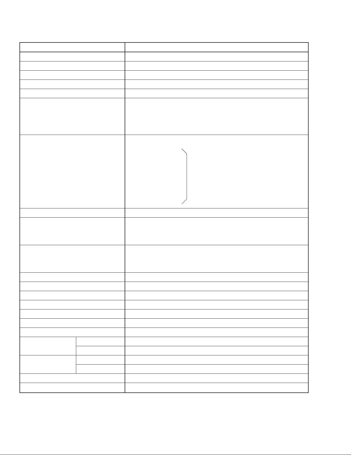
SPECIFICATIONS
Item Content
Dimensions (W × H × D) 462mm × 340.5mm × 375mm
Mass 10kg
TV RF System CCIR (M) & (N)
Color System NTSC / PAL-M / PAL-N
Sound Multiplex System BTSC (Multi-channel sound)
TV Receiving Channel and Frequency
VHF (VL) Band (02 ~ 06) 54MHz ~ 88MHz
VHF (VH) Band (07 ~ 13) 174MHz ~ 216MHz
UHF Band (14 ~ 69) 470MHz ~ 806MHz
CATV Receiving Channel and Frequency
Low Band (02 ~ 06)
High Band (07 ~ 13)
Mid Band (14 ~ 22)
Super Band (23 ~ 36) (54MHz ~ 804MHz)
Hyper Band (37 ~ 64)
Ultra Band (65 ~ 94, 100 ~ 125)
Sub Mid Band (01, 96 ~ 99)
TV/CATV Total Channel 180 Channels
Intermediate Frequency
VIF Carrier 45.75MHz
SIF Carrier 41.25MHz (4.5MHz)
Color Sub Carrier Frequency NTSC: 3.579545MHz
PAL-M: 3.57561149MHz
PAL-N: 3.58205625MHz
Aerial Input Terminal 75Ω Unbalanced
Power Input Rating: AC110 ~ 240V, 50/60Hz Operating: AC90 ~ 260V, 50/60Hz
Power Consumption 44W
Picture Tube Visible size : 34cm measured diagonally
High Voltage 22.5kV ± 1kV (at zero beam current)
Speaker 5cm × 9 cm Oval type × 2
Audio Output 1.5W+1.5W (Stereo)
Input Video 1Vp-p, 75Ω
Audio (L/R) 500mVrms (−4dBs), High impedance
Output Video 1Vp-p, 75Ω
Audio (L/R) 500mVrms (–4dBs), Low impedance
Headphone Jack Stereo mini jack (3.5ø)
Remote Control Unit RM-C373-1H (Battery size : AA/R06/UM-3 × 2)
Design & specifications are subject to change without notice.
No. 560832
Page 3

SAFETY PRECAUTIONS
AC VOLTMETER
(HAVING 1000Ω/V,
OR MORE SENSITIVITY)
PLACE THIS PROBE
ON EACH EXPOSED
METAL PART
1500Ω 10W
0.15µF AC-TYPE
GOOD EARTH GROUND
AV-14F3PX
1. The design of this product contains special hardware, many
circuits and components specially for safety purposes. For continued protection, no changes should be made to the original
design unless authorized in writing by the manufacturer. Replacement parts must be identical to those used in the original
circuits. Service should be performed by qualified personnel
only.
2. Alterations of the design or circuitry of the products should not
be made. Any design alterations or additions will void the
manufacturer's warranty and will further relieve the manufacturer of responsibility for personal injury or property damage
resulting therefrom.
3. Many electrical and mechanical parts in the products have special safety-related characteristics. These characteristics are often not evident from visual inspection nor can the protection
afforded by them necessarily be obtained by using replacement components rated for higher voltage, wattage, etc. Replacement parts which have these special safety characteristics are identified in the parts list of Service manual. Electrical
components having such features are identified by shading on the schematics and by (!) on the parts list in Service manual. The use of a substitute replacement which does
not have the same safety characteristics as the recommended
replacement part shown in the parts list of Service manual may
cause shock, fire, or other hazards.
4. Don't short between the LIVE side ground and ISOLATED
(NEUTRAL) side ground or EARTH side ground when repairing.
Some model's power circuit is partly different in the GND. The
difference of the GND is shown by the LIVE : (#) side GND,
the ISOLATED (NEUTRAL) : (") side GND and EARTH : ($)
side GND. Don't short between the LIVE side GND and ISOLATED (NEUTRAL) side GND or EARTH side GND and never
measure with a measuring apparatus (oscilloscope etc.) the
LIVE side GND and ISOLATED (NEUTRAL) side GND or
EARTH side GND at the same time.
If above note will not be kept, a fuse or any parts will be broken.
5. If any repair has been made to the chassis, it is recommended
that the B1 setting should be checked or adjusted (See ADJUSTMENT OF B1 POWER SUPPLY).
6. The high voltage applied to the picture tube must conform with
that specified in Service manual. Excessive high voltage can
cause an increase in X-Ray emission, arcing and possible component damage, therefore operation under excessive high voltage conditions should be kept to a minimum, or should be prevented. If severe arcing occurs, remove the AC power immediately and determine the cause by visual inspection (incorrect
installation, cracked or melted high voltage harness, poor soldering, etc.). To maintain the proper minimum level of soft XRay emission, components in the high voltage circuitry including the picture tube must be the exact replacements or alternatives approved by the manufacturer of the complete product.
8. When service is required, observe the original lead dress. Extra precaution should be given to assure correct lead dress in
the high voltage circuit area. Where a short circuit has occurred,
those components that indicate evidence of overheating should
be replaced. Always use the manufacturer's replacement components.
9. Isolation Check
(Safety for Electrical Shock Hazard)
After re-assembling the product, always perform an isolation
check on the exposed metal parts of the cabinet (antenna terminals, video/audio input and output terminals, Control knobs,
metal cabinet, screw heads, earphone jack, control shafts, etc.)
to be sure the product is safe to operate without danger of electrical shock.
(1) Dielectric Strength Test
The isolation between the AC primary circuit and all metal parts
exposed to the user, particularly any exposed metal part having a return path to the chassis should withstand a voltage of
3000V AC (r.m.s.) for a period of one second.
(. . . . Withstand a voltage of 1100V AC (r.m.s.) to an appliance
rated up to 120V, and 3000V AC (r.m.s.) to an appliance rated
200V or more, for a period of one second.)
This method of test requires a test equipment not generally
found in the service trade.
(2) Leakage Current Check
Plug the AC line cord directly into the AC outlet (do not use a
line isolation transformer during this check.). Using a "Leakage
Current Tester", measure the leakage current from each exposed metal part of the cabinet, particularly any exposed metal
part having a return path to the chassis, to a known good earth
ground (water pipe, etc.). Any leakage current must not exceed
0.5mA AC (r.m.s.).
However, in tropical area, this must not exceed 0.2mA AC
(r.m.s.).
● Alternate Check Method
Plug the AC line cord directly into the AC outlet (do not use a
line isolation transformer during this check.). Use an AC voltmeter having 1000 ohms per volt or more sensitivity in the following manner. Connect a 1500Ω 10W resistor paralleled by a
0.15µF AC-type capacitor between an exposed metal part and
a known good earth ground (water pipe, etc.). Measure the AC
voltage across the resistor with the AC voltmeter. Move the
resistor connection to each exposed metal part, particularly any
exposed metal part having a return path to the chassis, and
measure the AC voltage across the resistor. Now, reverse the
plug in the AC outlet and repeat each measurement. Any voltage measured must not exceed 0.75V AC (r.m.s.). This corresponds to 0.5mA AC (r.m.s.).
However, in tropical area, this must not exceed 0.3V AC (r .m.s.).
This corresponds to 0.2mA AC (r.m.s.).
7. Do not check high voltage by drawing an arc. Use a high voltage meter or a high voltage probe with a VTVM. Discharge the
picture tube before attempting meter connection, by connecting a clip lead to the ground frame and connecting the other
end of the lead through a 10kΩ 2W resistor to the anode button.
No. 56083 3
Page 4

AV-14F3PX
FEATURES
● New chassis design enables use of an interactive on-screen control.
● Wide range voltage for AC power input.
● With AUDIO / VIDEO INPUT & OUTPUT terminals.
● MUTING button can reduce the audio level to zero instantly.
● Functional remote control to operate TV set (for channel select, volume control, power ON/OFF, etc.) from a distance.
2
C bus is used to control V/C & DEF 1 chip IC, tuner, etc.
● I
● By means of AUTO PROGRAM, the TV stations can be selected automatically and the TV channels can also be rearranged
automatically.
● Built-in RETURN +.
● Built-in RTC (real-time clock) enables ON/OFF timer settings.
SPECIFIC SERVICE INSTRUCTIONS
DISASSEMBLY PROCEDURE
REMOVING THE REAR COVER
1. Unplug the AC power cord.
2. Remove the 5 screws marked "A" and 2 screws marked "B".
3. Withdraw the rear cover backward.
REMOVING THE MAIN PW BOARD
● After removing the rear cover.
1. Slightly raise both sides of the Main PW Board by hand and
remove the PB stopper "C" from the cabinet.
2. Withdraw the Main PW Board backward.
(If necessary, take off the wire clamp, connectors etc.)
REMOVING THE SPEAKER
● After removing the rear cover.
1. Remove the 2 screws marked "D".
2. Follow the same step for removing the other hand speaker.
CHECKING THE MAIN PW BOARD
T o check the back side of the Main PW Board, follow the next steps.
1. Pull out the Main PW Board. (Refer to "REMOVING THE MAIN
PW BOARD".)
2. Erect the Main PW Board vertically so that you can easily check
its back side.
CAUTION:
● When erecting the Main PW Board, be careful so that there will
be no contacting with other PW Board.
● Before turning on power, make sure that all connectors are properly connected.
WIRE CLAMPING AND CABLE TYING
1. Be sure to clamp the wire.
2. Never remove the cable tie used for tying the wires together.
Should it be inadvertently removed, be sure to tie the wires with
a new cable tie.
No. 560834
Page 5
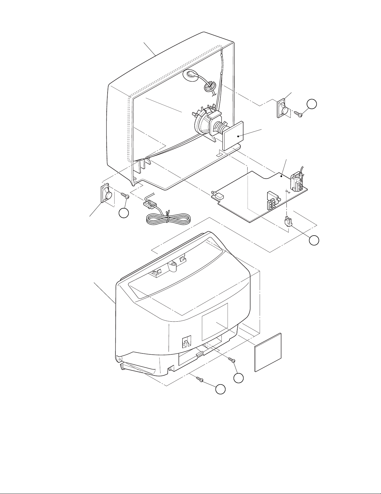
FRONT CABINET
SPEAKER
D
CRT SOCKET PWB
(Within MAIN PWB)
MAIN PWB
AV-14F3PX
(×2)
SPEAKER
REAR COVER
D
(×2)
A
(×5)
C
B
(×2)
No. 56083 5
Page 6
AV-14F3PX
REPLACEMENT OF MEMORY IC
1. MEMORY IC
This TV uses the following memory IC.
Memory IC: IC1704 on MAIN PW Board
The memory IC memorizes data for correctly operating the
video and deflection circuits. When replacing the memory IC,
be sure to use the same type IC written with the initial values
of data. In other words, use the specific IC listed in "PRINTED
WIRING BOARD PARTS LIST". For its mounting location, refer to "ADJUSTMENT LOCATIONS".
2. PROCEDURE FOR REPLACING MEMORY IC
(1) Power off
Switch the power off and unplug the power cord from the
wall outlet.
(2) Replacing the memory IC
Replace the memory IC with new one. Be sure to use the
memory IC written with the initial data values.
(3) Power on
Plug the power cord into the wall outlet and switch the
power on.
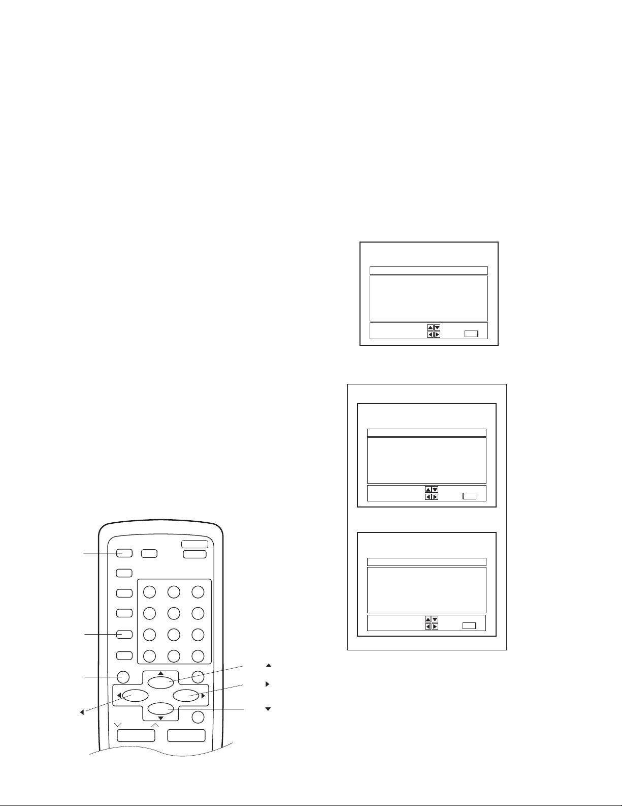
(4) Check and setting of SYSTEM CONSTANT SET:
1) Press the DISPLAY key and the VIDEO STATU key on
the remote control unit simultaneously.
The SERVICE MENU screen will be displayed. (See
Fig. 1.)
2) In the SERVICE MENU, again press the DISPLA Y key
and the VIDEO STATU key simultaneously. Then, the
SYSTEM CONSTANT SET screen will be displayed.
(See Fig. 2.)
3) Check whether the setting values of the SYSTEM CONSTANT SET are the same as those indicated in Table
1. If the value is different, select the setting item with
the MENU 1/4 key, and set the correct value with the
MENU 2/3 key.
(The selected value will be stored in memory when the
MENU 2/3 key is released.)
4) Press the EXIT key twice to return to the normal screen.
NAME OF REMOTE CONTROL KEYS
(5) Receive channel setting
Refer to the OPERATING INSTRUCTIONS and set the
receive channels (channels preset).
(6) User settings
Check the user setting items in Tables 2-1 and 2-2, and if
setting value is different, set the correct value.
For setting, refer to the OPERATING INSTRUCTIONS.
(7) Setting of SERVICE MENU
Verify the setting for each setting item in the SERVICE
MENU. (See Table 3.) If readjustment is necessary, perform adjustment referring to "SERVICE ADJUSTMENTS".
SERVICE MENU
PICTURE SOUND
VIDEO STATUS OTHERS
LOW LIGHT HIGH LIGHT
RF AFC CHK
VCO (CW) I2C BUS CTRL
SELECT BY
OPERATE BY
EXIT BY
EXIT
IT
Fig. 1
SYSTEM CONSTANT-I
SYSTEM CONSTANT
VIDEO : 2
AUDIO : MTS
VARI. OUT : NO
GAME : YES
CINEMA : YES
SELECT BY
OPERATE BY
EXIT BY
EXIT
IT
SYSTEM CONSTANT-II
DISPLAY
VIDEO STATUS
EXIT
MENU
DISPLAY
PICTURE
BOOSTER
CLOSED
CAPTION
SLEEP
TIMER
VIDEO
STATUS
COLOUR
SYSTEM
EXIT
CHANNEL
TV/VIDEO
100+
MENU
POWER
1
23
456
78
0
HYPER SURROUND
VOLUME
−
RETURN+
MUTING
+
SYSTEM CONSTANT
CCD : YES
RETURN+ : YES
SURROUND :
✽✽✽✽✽✽✽✽
9
MENU
MENU
MENU
SELECT BY
OPERATE BY
✽✽✽✽✽
Fig. 2
YES
EXIT BY
EXIT
IT
No. 560836
Page 7
SETTING OF SYSTEM CONSTANT SET
Table 1
Setting item Setting contents Se tting value
AV-14F3PX
VIDEO 2
AUDIO MTS
VARI. OUT NO
GAME YES
CINEMA YES
CCD YES
RETURN+ YES
SURROUND YES
USER SETTING VALUES
● Setting of Function
Setting item Setting value Setting item Setting value
MAIN POWER OFF SLEEP TIMER 0
SUB POWER ON VIDEO STATUS STANDARD
CHANNEL CH 02 CLOSED CAPTION OFF (CC1/T1)
CHANNEL PRESET Refer to OPERATING INSTRUCTIONS COLOR SYSTEM AUTO
VOLUME 10 HYPER SURROUND OFF
TV/VIDEO TV PICTURE BOOSTER OFF
DISPLAY OFF
12
MONO PH. MONO MTS
YES NO
YES NO
YES NO
YES NO
YES NO
YES NO
Table 2-1
● Setting of Menu
Setting item Setting value Setting item Setting value
TINT CENTER ON/OFF TIMER NO
COLOR CENTER CHANNEL SUMMARY Unnecessary to set
PICTURE CENTER SET LOCK CODE Unnecessary to set
BRIGHT CENTER CHILD LOCK OFF
DETAIL CENTER AUTO TUNER SETUP AIR
BASS CENTER NOISE MUTING OFF
TREBLE CENTER BACKGROUND BLACK
BALANCE CENTER CLOSED CAPTION CC1 / T1
MTS STEREO LANGUAGE ENG.
SET CLOCK Unnecessary to set
Table 2-2
No. 56083 7
Page 8
AV-14F3PX
SERVICE MENU SETTING ITEMS
Table 3
Service menu Setting itemService menu Setting item
PICTURE 1. PICTURE
2. BRIGHT
3. COL. PALM
4. COL. PALN
5. COL. NTSC
6. TINT
7. TV DTL
8. EXT PIC.
9. EXT BRI.
10. EXT COL.
11. EXT TINT
12. EXT DTL
13. P/N KILL
14. Y S CONT
15. TV Y-DL
16. EXT Y-DL
17. WPL SW
18. Y GAMMA
19. P/N G P.
20. COL. L SW
21. COL. LMT.
22. PN C. ATT
23. OFST. SW
24. OFST. B-Y
25. OFST. R-Y
26. C-TOF SW
27. TV T FO
28. TV T Q
29. EXT T FO
30. EXT T Q
31. C-TRAP
32. C-TR. FO
33. C-TRAP Q
34. FIX B/W
35. APA P. FO
36. DC TRAN.
37. B. ST. SW
38. B. ST. PO.
39. ABL GAIN
40. ABL PO.
41. HALF T.
42. DRV G SW
43. NT. COMB
44. COIN DET
45. NOISE L.
46. VCD MODE
47. V AGC SP
48. H POS. 50
49. H BLK. 50
50. V POS. 50
51. V SIZE50
52. V S CR50
53. V LIN. 50
Do not adjust.
Do not adjust.
54. H POS. 60
55. H BLK. 60
56. V POS. 60
57. V SIZE60
58. V S CR60
59. V LIN. 60
60. RF AGC
SOUND 1. NOISE
2. IN LEVEL
3. FH MON.
4. ST VCO
5. PILOT
6. FILTER
7. LOW SEP.
8. HI SEP.
9. 5FH MON.
10. SAP VCO
11. IN GAIN
12. FIL. OFF.
VIDEO STATUS TINT
COLOR
PICTURE
BRIGHT
DETAIL
G DRIVE
B DRIVE
R CUT.
G CUT.
B CUT.
OTHERS 1. OSD HP
2. OSD VP
3. H-CK SW
LOW LIGHT R CUTOFF
G CUTOFF
B CUTOFF
HIGH LIGHT G DRIVE
B DRIVE
RF AFC CHK RF AFC
FINE
VCO (CW) IF VCO (CW) adjustment mode
I2C BUS CTRL I2C BUS
(Fixed to ON state.)
Do not adjust.
Do not adjust.
Do not adjust.
Do not adjust.
Do not adjust.
Do not adjust.
No. 560838
Page 9
REPLACEMENT OF CHIP COMPONENT
■ CAUTIONS
1. Avoid heating for more than 3 seconds.
2. Do not rub the electrodes and the resist parts of the pattern.
3. When removing a chip part, melt the solder adequately.
4. Do not reuse a chip part after removing it.
■ SOLDERING IRON
1. Use a high insulation soldering iron with a thin pointed end
of it.
2. A 30W soldering iron is recommended for easily removing
parts.
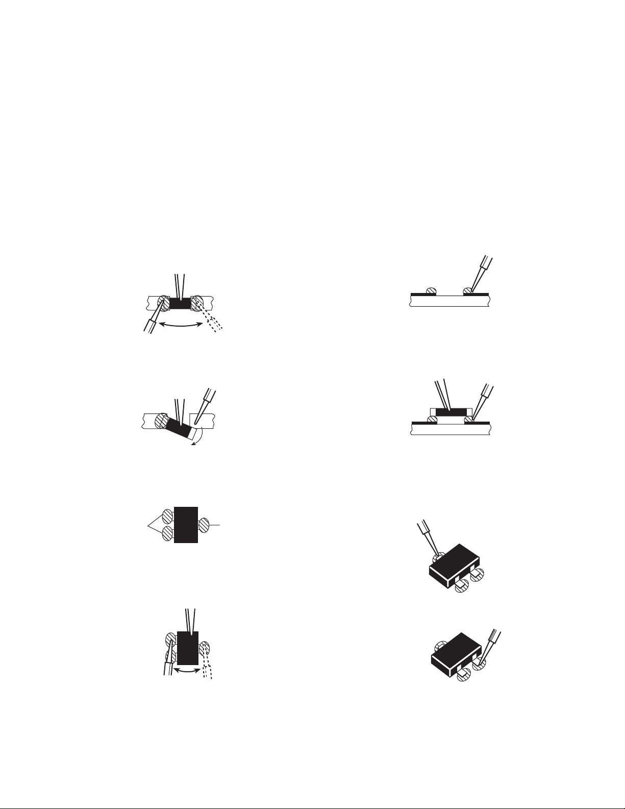
■ REPLACEMENT STEPS
1. How to remove Chip parts
● Resistors, capacitors, etc.
(1) As shown in the figure, while pushing the chip part with twee-
zers, alternately melt the solder at its each end.
AV-14F3PX
2. How to install Chip parts
● Resistors, capacitors, etc.
(1) Apply solder to the pattern as indicated in the figure.
(2) Shift the chip part with tweezers and remove it.
● Transistors, diodes, variable resistors, etc.
(1) Apply extra solder to each lead.
SOLDER
(2) As shown in the figure, while pushing the chip part with twee-
zers, alternately melt the solder at its each lead. Then, shift
and remove the chip part.
SOLDER
(2) Grasp the chip part with tweezers and place it on the solder.
Then heat and melt the solder at both ends of the chip part.
● Transistors, diodes, variable resistors, etc.
(1) Apply solder to the pattern as indicated in the figure.
(2) Grasp the chip part with tweezers and place it on the solder.
(3) First solder lead A as indicated in the figure.
A
B
C
(4) Then solder leads B and C.
A
Note : After removing the part, remove remaining solder from
the pattern.
No. 56083 9
B
C
Page 10

AV-14F3PX
SERVICE ADJUSTMENTS
BEFORE STARTING SERVICE ADJUSTMENT
1. There are 2 ways for adjusting this TV: One is with the
REMOTE CONTROL UNIT and the other is the conventional
method using adjustment parts and components.
2. The setting (adjustment) using the REMOTE CONTROL
UNIT is made on the basis of the initial setting values. The
setting values which adjust the screen to the optimum condition can be different from the initial setting values.
3. Make sure that connection is correctly made to AC power source.
4. Turn on the power of the TV and measuring instrument for warming up for at least 30 minutes before starting adjustment.
5. If the receive or input signal is not specified, use the most appropriate signal for adjustment.
6. Never touch parts (such as variable resistors, transformers and
capacitors) not shown in the adjustment items of this service
adjustment.
7. Preparation for adjustment (presetting):
Unless otherwise specified in the adjustment items, preset the
following functions with the remote control unit.
VIDEO STATUS
BASS, TREBLE, BALANCE
TINT, COLOR, PICTURE, BRIGHT
DETAIL
Function
Setting value
STANDARD
CENTER
CENTER
MEASURING INSTRUMENT
ADJUSTMENT/CHECK ITEMS
AND FIXTURES
Adjustment/Check item Page
1. DC voltmeter (or Digital voltmeter)
2. Oscilloscope
3. Signal generator (Pattern generator)
[PAL / SECAM / NTSC]
4. Remote control unit
5. TV audio multiplex signal generator
6. Frequency counter
B1 POWER SUPPLY Check 16
IF VCO Adjustment 16
RF AGC Adjustment 16
FOCUS Adjustment 16
DEFLECTION CIRCUIT Adjustment 17
VIDEO/CHROMA CIRCUIT Adjustment 18
VIDEO STATUS Adjustment 21
MTS CIRCUIT (AUDIO CIRCUIT) Adjustment 22
X-RAY PROTECTION Check 23
PURITY, CONVERGENCE Adjustment 24
BASIC OPERATION IN SERVICE MENU
1. TOOL OF SERVICE MENU OPERATION
Operate the SERVICE MENU with the remote control unit.
2. SERVICE MENU ITEMS
With the SERVICE MENU, various settings (adjustments) can be made, and they are broadly classified in the following items of settings:
● PICTURE..................... For entering/adjusting the setting values (adjustment values) of the VIDEO/CHROMA and DEFLECTION cir-
● SOUND........................ For entering/adjusting the setting values (adjustment values) of the AUDIO circuits.
● VIDEO STATUS .......... For setting the values for CINEMA and GAME.
● OTHERS...................... For setting the values of other items.
● LOW LIGHT................. For setting the values of WHITE BALANCE circuit.
● HIGH LIGHT ................ For setting the values of WHITE BALANCE circuit .
● RF AFC CHK ............... For checking the RF AFC circuit. (Do not adjust.)
● VCO (CW) ................... For adjusting the IF circuit.
● I2C BUS CTRL............. I2C BUS ON/OFF CONTROL. (Fixed to ON.)
cuits.
No. 5608310
Page 11

AV-14F3PX
3. BASIC OPERATION IN SERVICE MENU
NOTE: In each menu screen, key operation guide will appear
at the bottom, which will help your menu operation.
(1) How to enter SERVICE MENU
Press the DISPLAY key and the VIDEO STATUS key on the
remote control unit simultaneously.
The SERVICE MENU screen will be displayed. (See Fig. 1.)
• To return to the previous screen, press the EXIT key on
the remote control unit.
(2) Selection of Sub Menu Screen
See Fig. 3, menu diagram, on the next page.
1) Press the MENU 1/4 key on the remote control unit to
select an item in the SERVICE MENU screen.
2) Enter the Sub Menu as follows:
● Entering "PICTURE", "SOUND", and "OTHERS"
Sub Menus
Press the MENU 2/3 key in the SERVICE MENU
screen. Then, the Screen A shown in Fig. 3 on the
next page will appear.
In the Screen A, press the MENU 1/4 key to enter
the Sub Menu screen.
● Entering other than above Sub Menus
Press the MENU 2/3 key in the SERVICE MENU
screen. Then, the Sub Menu screen will directly appear.
• To return to the previous screen, press the EXIT key on
the remote control unit.
SERVICE MENU
SERVICE MENU
PICTURE SOUND
VIDEO STATUS OTHERS
LOW LIGHT HIGH LIGHT
RF AFC CHK
VCO (CW) I2C BUS CTRL
SELECT BY
OPERATE BY
EXIT BY
EXIT
SERVICE MENU items
Key Operation Guide
1/4 key: Press to select an item.
2/3 key: Press to enter the SUB MENU screen of the
selected item.
EXIT key:Press to return to the previous screen.
Fig. 1 SERVICE MENU
SERVICE MENU → SUB MENU
PICTURE SOUND
VIDEO STATUS OTHERS
LOW LIGHT HIGH LIGHT
RF AFC CHK
VCO (CW) I2C BUS CTRL
IT
(3) Method of Setting in the Sub Menu Screen
* Once the setting values are set, they are automatically
memorized.
1) PICTURE, SOUND, VIDEO STATUS, OTHERS
1/4 key: Press to select an item in the Sub Menu.
2/3 key: Press to select the value of the selected item.
EXIT key: Press to return to the previous screen.
VIDEO STATUS key: In the VIDEO STATUS sub menu
screen, press to switch between VIDEO STATUS-GAME and VIDEO STATUS-CINEMA.
2) LOW LIGHT, HIGH LIGHT
Setting will be done by using the numeral key on the remote control unit.
3) RF AFC CHK
Do not adjust.
4) VCO (CW)
Setting will be done by adjusting the CW TRANSF . (T1 11)
on the Main PWB.
5) I2C BUS CTRL
Do not adjust. This item should always be fixed to ON to
normally operate the TV set.
(4) Release of SERVICE MENU
After completing the setting, repeatedly press the EXIT key
until the screen returns to the normal screen.
Fig. 2
SUB MENU: PICTURE
1. PICTURE
✽✽✽✽✽ ✽✽✽✽
SELECT BY
OPERATE BY
✽✽✽
EXIT BY
EXIT
IT
SUB MENU item
Setting Value
1/4 key: Press to select an item.
2/3 key: Press to set the value.
EXIT key:Press to return to the previous screen.
Fig. 2 SUB MENU example (PICTURE)
No. 56083 11
Page 12

AV-14F3PX
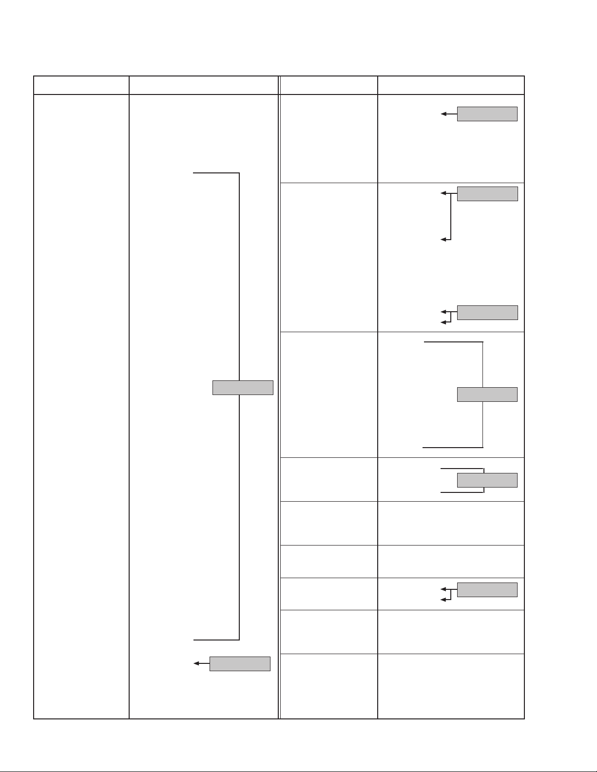
SERVICE MENU AND SUB MENU SCREENS
SERVICE MENU (MAIN MENU)
SERVICE MENU
PICTURE SOUND
VIDEO STATUS OTHERS
LOW LIGHT HIGH LIGHT
RF AFC CHK
VCO (CW) I2C BUS CTRL
SELECT BY
OPERATE BY
EXIT BY
EXIT
IT
SUB MENU: HIGH LIGHT
HIGH LIGHT
✽✽✽ ✽✽✽
EXIT BY
EXIT
IT
SUB MENU: RF AFC CHK
SCREEN A
SELECT BY EXIT BY
EXIT
SUB MENU: SOUND
1. NOISE
STATUS
SELECT BY
OPERATE BY
✽✽✽
✽✽✽✽✽✽✽✽
EXIT BY
EXIT
SUB MENU: PICTURE
1. PICTURE
✽✽✽✽✽ ✽✽✽✽
SELECT BY
IT
OPERATE BY
✽✽✽
EXIT BY
EXIT
IT
SUB MENU: OTHERS
1. OSD HP
SELECT BY
IT
OPERATE BY
✽✽✽
EXIT BY
EXIT
IT
RF AFC ON
FINE
SELECT BY
OPERATE BY
Do not adjust.
SUB MENU: VCO (CW)
TOO HIGH
ABOVE REFERENCE
BELOW REFERE NCE
TOO LOW
SYNC : YES
SUB MENU: I C BUS CTRL
I2C BUS ON
OPERATE BY
2
✽✽✽
EXIT BY
EXIT
EXIT BY
EXIT
EXIT BY
EXIT
IT
SUB MENU: VIDEO STATUS
CINEMA
CINEMA
TINT G DRIVE
COLOR B DRIVE
PICTURE R CUT.
BRIGHT G CUT.
DETAIL B CUT.
SELECT BY
IT
OPERATE BY
✽✽✽ ✽✽✽
✽✽✽ ✽✽✽
✽✽✽ ✽✽✽
✽✽✽ ✽✽✽
✽✽✽ ✽✽✽
EXIT BY
EXIT
IT
Press
VIDEO
STATUS
Key.
GAME
TINT G DRIVE
COLOR B DRIVE
PICTURE R CUT.
BRIGHT G CUT.
DETAIL B CUT.
SELECT BY
OPERATE BY
GAME
✽✽✽ ✽✽✽
✽✽✽ ✽✽✽
✽✽✽ ✽✽✽
✽✽✽ ✽✽✽
✽✽✽ ✽✽✽
EXIT BY
EXIT
IT
SUB MENU: LOW LIGHT
BRIGHT
IT
BRIGHT
✽✽✽
✽✽✽ ✽✽✽
✽✽✽
EXIT BY
EXIT
IT
Fixed to ON state.
Fig. 3
No. 5608312
Page 13

ADJUSTMENT LOCATIONS
MAIN PWB
ON
TIMER
POWER
VOL-+CH
-
+
AV-14F3PX
FRONT
MENU
DEG
PW
S901
POWER SW
REMOCON
RECEIVER
F901
IC701
T
IC201
MPX
MEMORY
TU001
IC704
IC
VCO
C
T111
S
HV
X
3
1
U
13
B1
HVT
CRT SOCKET PWB
(SOLDER SIDE)
1 Pin TP-91(B1)
2 Pin NC
3 Pin TP-E
(")
TOP
UPPER : FOCUS
LOWER : SCREEN
T
TP-E
U
TP-47B
1
E
CRT EARTH
(BRAIDED ASS'Y)
No. 56083 13
Page 14

AV-14F3PX
INITIAL SETTING VALUE OF SERVICE MENU
The setting (adjustment) using the remote control unit is made on the basis of the initial setting values.
The setting values which adjust the screen to the optimum condition can be different from the initial setting values.
● Do not change the initial setting values of the setting (adjustment) items not listed in "ADJUSTMENTS".
● PICTURE
★ The following four setting items in the video mode and TV mode are linked each other.
Video mode: 8. EXT PIC., 9. EXT BRI., 10. EXT COL. and 11. EXT TINT
TV mode: 1. PICTURE, 2 . BRIGHT, 5. COL. NTSC and 6. TINT
When the setting items in the TV mode are adjusted, the same values will be set to the linking items in the video mode. For example,
if the value of 1. PICTURE is changed, the value of 8. EXT PIC. will also be changed accordingly. (The initial setting values given in
( ) are offset values against the TV mode.)
★ When the four items (Nos. 8, 9, 10 and 11) are adjusted in the video mode, the setting values will be changed independently from
those in the TV mode.
Setting item Variable range Initial setting value
1. PICTURE 000 ~ 127 040
2. BRIGHT 000 ~ 127 064
3. COL. PALM 000 ~ 127 070
4. COL. PALN 000 ~ 127 070
5. COL. NTSC 000 ~ 127 072
6. TINT 000 ~ 127 065
7. TV DTL 000 ~ 063 028
8. EXT PIC. ±025 (±000)
9. EXT BRI. ±025 (+000)
10. EXT COL. ±025 (±000)
11. EXT TINT ±025 (+001)
12. EXT DTL 000 ~ 063 030
13. P/N KILL 000 / 001 001
14. Y S CONT 000 ~ 031 031
15. TV Y-DL 000 ~ 007 001
16. EXT Y-DL 000 ~ 007 002
17. WPL SW 000 / 001 000
18. Y GAMMA 000 / 001 000
19. P/N G P. 000 / 001 000
20. COL. L SW 000 / 001 001
21. COL. LMT. 000 ~ 003 001
22. PN C. ATT 000 ~ 003 001
23. OFST. SW 000 / 001 000
24. OFST. B-Y 000 ~ 015 008
25. OFST. R-Y 000 ~ 015 008
26. C-TOF SW 000 / 001 001
27. TV T FO 000 ~ 003 001
28. TV T Q 000 ~ 003 000
29. EXT T FO 000 ~ 003 000
30. EXT T Q 000 ~ 003 000
Settingitem Variable range Initial setting value
31. C-TRAP 000 / 001 000
32. C-TR. FO 000 ~ 003 002
33. C-TRAP Q 000 ~ 003 000
34. FIX B/W 000 / 001 000
35. APA P. FO 000 ~ 003 001
36. DC TRAN. 000 ~ 007 006
37. B. ST. SW 000 / 001 000
38. B. ST. PO. 000 ~ 007 000
39. ABL GAIN 000 ~ 007 004
40. ABL PO. 000 ~ 007 000
41. HALF T. 000 ~ 002 001
42. DRV G SW 000 / 001 000
43. NT. COMB 000 / 001 001
44. COIN DET 000 ~ 003 001
45. NOISE L. 000 ~ 003 003
46. VCD MODE 000 / 001 000
47. V AGC SP 000 / 001 000
48. H POS. 50 000 ~ 031 007
49. H BLK. 50 000 ~ 007 000
50. V POS. 50 000 ~ 007 000
51. V SIZE50 000 ~ 127 024
52. V S CR50 000 ~ 127 018
53. V LIN. 50 000 ~ 031 004
54. H POS. 60 000 ~ 031 012
55. H BLK. 60 000 ~ 007 000
56. V POS. 60 000 ~ 007 000
57. V SIZE60 000 ~ 127 028
58. V S CR60 000 ~ 127 046
59. V LIN. 60 000 ~ 031 004
60. RF AGC 000 ~ 255 160
: Do not adjust.
No. 5608314
Page 15

● SOUND
AV-14F3PX
Setting item Variable range Initial setting value
1. NOISE 000 / 001 001
2. IN LEVEL 000 ~ 063 020
3. FH MON. 000 / 001 000
4. ST VCO 000 ~ 063 025
5. PILOT 000 / 001 000
6. FILTER 000 ~ 063 030
: Do not adjust.
● VIDEO STATUS
Setting item Variable range
TINT ±20 ±0 ±0
COLOR ±20 −3 −3
PICTURE ±20 −10 −10
BRIGHT ±20 ±0 ±0
DETAIL ±15 ±0 −5
G DRIVE −99 ~ +50 −22 ±0
B DRIVE −99 ~ +50 −54 ±0
R CUT. ±10 ±0 ±0
G CUT. ±10 ±0 ±0
B CUT. ±10 ±0 ±0
Initial setting value
CINEMA GAME
Setting item Variable range Initial setting value
7. LOW SEP. 000 ~ 063 022
8. HI SEP. 000 ~ 063 023
9. 5FH MON. 000 / 001 000
10. SAP VCO 000 ~ 063 026
11. IN GAIN 000 / 001 000
12. FIL. OFF. ±010 ±000
: Do not adjust.
● OTHERS
Setting item Variable range Initial setting value
1. OSD HP 000 ~ 063 023
2. OSD VP 000 ~ 015 012
3. H-CK SW 000 / 001 000
: Do not adjust.
● LOW LIGHT
Setting item Variable range Initial setting value
R CUTOFF 000 ~ 255 020
G CUTOFF 000 ~ 255 020
B CUTOFF 000 ~ 255 020
● HIGH LIGHT
Setting item Variable range Initial setting value
G DRIVE 000 ~ 255 128
B DRIVE 000 ~ 255 128
● RF AFC CHK
Setting item Variable range Initial setting value
RF AFC ON / OFF ON
FINE −77 ~ +77 xx
: Do not adjust.
● I2C BUS CTRL
Setting item Variable range Initial setting value
I2C BUS ON / OFF ON (Fixed to ON)
: Do not adjust.
No. 56083 15
Page 16

AV-14F3PX
ADJUSTMENTS
B1 POWER SUPPLY CHECK
Item Test point Adjustment part
Measuring
instrument
Check of ● Signal B1 (TP-91)
B1 POWER Generator TP-E (
""
")
""
SUPPLY ● DC [B1
voltmeter connector]
IF VCO ADJUSTMENT
Item Test point Adjustment part
Adjustment ● Signal CW TRANSF.
VCO (CW) Generator (T111)
Measuring
instrument
● Remote
control unit [MAIN PWB]
SUB MENU: VCO (CW)
TOO HIGH
ABOVE REFERENCE
BELOW REFERE NCE
TOO LOW
SYNC : YES
EXIT BY
EXIT
IT
YELLOW
Description
1. Receive a black and white signal (color off). (NTSC)
2. Connect a DC voltmeter between B1 (TP-91) and TP-E (")
(between pins 1 and 3 of the connector B1).
3. Make sure that the voltage is DC134.5 ± 2.0V.
Description
● Under normal conditions, no adjustment is required.
1. Receive any broadcast. (Use a channel without offset frequency.)
2. Select the sub menu screen VCO (CW) from the SERVICE
MENU. (More specifically, in the SERVICE MENU, press the
MENU 1/4 key to select VCO (CW) and then press the MENU
2/3 key to enter the sub menu screen VCO (CW) .)
3. Confirm that the color of "TOO HIGH" and "TOO LOW" changes
in yellow as you turn the CW TRANSF. At this time, check that
"SYNC: YES" appears on the screen.
4. Slowly turn the CW TRANSF. until "BELOW REFERENCE"
changes to yellow. Also, at this time, check that "SYNC: YES"
appears on the screen.
5. Press the EXIT key to return to the normal screen.
RF AGC ADJUSTMENT
Item Test point Adjustment part
Adjustment Remote 60. RF AGC
of RF AGC control unit
Measuring
instrument
FOCUS ADJUSTMENT
Item Test point Adjustment part
Adjustment Signal FOCUS VR
of FOCUS generator [In HVT]
Measuring
instrument
Description
1. Receive any broadcast.
2. Select the sub menu screen PICTURE from the SERVICE
MENU.
3. Select 60. RF AGC with the MENU 1/4 key.
4. Press the MUTING key to turn off the color.
5. Press the MENU 2 key to get noise on the screen picture. (The
setting value will be decreased.)
6. Press the MENU 3 key until noise disappears from the screen.
7. Change to other channels and make sure that there is no irregularity on the screen picture.
8. Press the MUTING key to turn on the color.
Description
1. Receive a cross-hatch signal.
2. While watching the screen, adjust the FOCUS VR to make the
vertical and horizontal lines as fine and sharp as possible.
3. Make sure that, when the screen is darkened, the lines remain
in good focus.
No. 5608316
Page 17

DEFLECTION CIRCUIT ADJUSTMENT
The setting (adjustment) using the remote control unit is made on the basis of the initial setting values shown on page 14.
The setting values which adjust the screen to the optimum condition can be different from the initial setting values.
● Do not change the initial setting values of the setting (adjustment) items not listed herein.
AV-14F3PX
Item Test point Adjustment part
Measuring
instrument
Adjustment ● Signal 56. V POS. 60
of generator 57. V SIZE60
V. HEIGHT 58. V S CR60
V. POSITION ● Remote 59. V. LIN. 60
V. LIN. control
V. S CR unit
50. V POS. 50
51. V SIZE50
52. V S CR50
53. V. LIN. 50
Screen size
Screen
size
92%
Picture
size
100%
Description
(60Hz)
1. Receive a cross-hatch signal. (NTSC or PAL-M)
2. Select the sub menu screen PICTURE from the SERVICE
MENU.
3. Select 56. V POS. 60 with the MENU 1/4 key, and confirm that
the setting value is 0.
NOTE: The value of 56. V POS. 60 should be fixed to 0.
4. Confirm the initial setting value of 57. V SIZE60, 58. V S CR60,
and 59. V. LIN. 60.
5. Adjust 57. V SIZE60 and make the vertical screen size 92% of
the picture size, with the MENU 2/3 key.
6. Adjust 59. V. LIN. 60 and 58. V S CR60 to get the best vertical
linearity, with the MENU 2/3 key.
(50Hz)
1. Receive a cross-hatch signal. (PAL-N)
2. In the sub menu screen PICTURE, select 50. V POS. 50, 51. V
SIZE50, 52. V S CR50, and 53. V. LIN. 50 with the MENU 1/4
key, and confirm their initial setting values.
3. Adjust 51. V SIZE 50 and make the vertical screen size 92% of
the picture size, with the MENU 2/3 key.
4. Adjust 53. V. LIN. 50 and 52.V S CR50 to get the best vertical
linearity, with the MENU 2/3 key.
5. Adjust 50. V POS. 50 so that the vertical center line comes
close to the CRT vertical center as much as possible, with the
MENU 2/3 key.
● Readjust V SIZE, V. LIN, V S CR if necessary.
Picture size 100%
Adjustment ● Signal 54. H POS.60
of generator
H. POSITION
● Remote
control
unit
48. H POS.50
(60Hz)
1. Receive a cross-hatch signal. (NTSC or PAL-M)
2. Select the sub menu screen PICTURE from the SERVICE
MENU.
3. Select 54. H POS.60 with the MENU 1/4 key.
4. Confirm the initial setting value of 54. H POS.60.
5. Adjust 54. H POS.60 so that the screen will be horizontally cen-
tered, with the MENU 2/3 key.
(50Hz)
1. Receive a cross-hatch signal. (PAL-N)
2. In the sub menu screen PICTURE, select 48. H POS.50 with
the MENU 1/4 key.
3. Confirm the initial setting value of 48. H POS.50.
4. Adjust 48. H POS.50 so that the screen will be horizontally cen-
tered, with the MENU 2/3 key.
No. 56083 17
Page 18

AV-14F3PX
VIDEO/CHROMA CIRCUIT ADJUSTMENT
The setting (adjustment) using the remote control unit is made on the basis of the initial setting values shown on pages 14 and
15.
The setting values which adjust the screen to the optimum condition can be different from the initial setting values.
● Do not change the initial setting values of the setting (adjustment) items not listed herein.
Item Test point Adjustment part
Measuring
instrument
Adjustment ● Signal BRIGHT
of WHITE generator
BALANCE R CUTOFF
(Low light) ● Remote G CUTOFF
control B CUTOFF
unit
SCREEN VR
(In HVT)
REMOTE CONTROL UNIT
H.LINE OFF
12 3
H.LINE ON
G. CUTOFF ( )
B. CUTOFF ( )
B. CUTOFF ( )
G. CUTOFF ( )
R. CUTOFF ( )
R. CUTOFF ( )
4
789
56
Description
1. Receive a black and white signal (color off).
2. Select the sub menu screen LOW LIGHT from the SERVICE
MENU.
3. Confirm that the value of BRIGHT, R CUTOFF, G CUTOFF,
and B CUTOFF is set to the initial setting value.
4. Press the 1 key on the remote control unit to produce a single
horizontal line.
5. Turn the SCREEN VR fully counterclockwise, then slowly turn
it clockwise to where a red, blue, or green color is faintly visible.
6. Use keys 4 ~ 9 on the remote control unit and adjust the other
2 colors to where the single horizontal line becomes white.
7. Turn the SCREEN VR to where the single horizontal line glows
faintly.
8. Press the 2 key to stop producing a single horizontal line.
NOTE: The key 3 acts in the same way as the EXIT key.
SUB MENU: LOW LIGHT
R CUTOFF
BRIGHT
BRIGHT
BRIGHT
✽✽✽
✽✽✽ ✽✽✽
✽✽✽
EXIT BY
EXIT
IT
G CUTOFF
B CUTOFF
Adjustment ● Signal G DRIVE
of WHITE generator B DRIVE
BALANCE
(High light) ● Remote
control
unit
REMOTE CONTROL UNIT
12 3
R. DRIVE ( )
R. DRIVE ( )
4
789
56
B. DRIVE ( )
B. DRIVE ( )
1. Receive a black and white signal (color off).
2. Select the sub menu screen HIGH LIGHT from the SERVICE
MENU.
3. Confirm that the value of G DRIVE and B DRIVE is set to the
initial setting value.
4. Use the keys 5 and 8 or 6 and 9 to produce a white screen.
NOTE: The key 3 acts in the same way as the EXIT key.
SUB MENU: HIGH LIGHT
G DRIVE
HIGH LIGHT
✽✽✽ ✽✽✽
EXIT BY
EXIT
IT
B DRIVE
No. 5608318
Page 19

AV-14F3PX
Item Test point Adjustment part
Adjustment Remote 2. BRIGHT
of control unit
SUB
BRIGHT
Adjustment Remote 1. PICTURE
of control unit
SUB CONT.
Adjustment Remote
of control unit
SUB
COLOR -I 3. COL. PALM
Measuring
instrument
Description
1. Receive any broadcast.
2. Select the sub menu screen PICTURE from the SERVICE
MENU.
3. Select 2. BRIGHT with the MENU 1/4 key, and confirm its
initial setting value.
4. If the brightness is not the best with the initial set value, make
fine adjustment until you get the best brightness, with the MENU
2/3 key.
1. Receive any broadcast.
2. Select the sub menu screen PICTURE from the SERVICE
MENU.
3. Select 1. PICTURE with the MENU 1/4 key, and confirm its
initial setting value.
4. If the contrast is not the best with the initial set value, make
fine adjustment until you get the best contrast, with the MENU
2/3 key.
[Method of adjustment without measuring instrument]
(PAL-M COLOR)
1. Receive a PAL-M broadcast.
2. Select the sub menu screen PICTURE from the SERVICE
MENU.
3. Select 3. COL. PALM with the MENU 1/4 key , and confirm its
initial setting value.
4. If the color is not the best with the initial set value, make fine
adjustment until you get the best color, with the MENU 2/3
key.
4. COL. PALN
5. COL. NTSC
(PAL-N COLOR)
1. Receive a PAL-N broadcast.
2. In the sub menu screen PICTURE, select 4. COL. PALN with
the MENU 1/4 key, and confirm its initial setting value.
3. If the color is not the best with the initial set value, make fine
adjustment until you get the best color, with the MENU 2/3
key.
(NTSC COLOR)
1. Receive a NTSC broadcast.
2. In the sub menu screen PICTURE, select 5. COL. NTSC with
the MENU 1/4 key, and confirm its initial setting value.
3. If the color is not the best with the initial set value, make fine
adjustment until you get the best color, with the MENU 2/3
key.
No. 56083 19
Page 20

AV-14F3PX
Item Test point Adjustment part
Measuring
instrument
Adjustment ● Signal TP-47B
of SUB generator TP-E (
""
")
""
COLOR-II [CRT
● Oscillo- SOCKET 3. COL. PALM
scope PWB]
● Remote
control
unit
Y
G
R
W
Cy
Mg
(A)
(−)
0V
(+)
4. COL. PALN
B
Description
[Method of adjustment using measuring instrument]
(PAL-M COLOR)
1. Receive a PAL-M full field color bar signal (75% white).
2. Select the sub menu screen PICTURE from the SERVICE
MENU.
3. Select 3. COL. PALM with the MENU 1/4 key, and confirm
its initial setting value.
4. Connect the oscilloscope between TP-47B and TP-E.
5. Adjust 3. COL. PALM to set the value (A) in the figure to +10V
(W & B), with the MENU 2/3 key.
(PAL-N COLOR)
1. Receive a PAL-N full field color bar signal (75% white).
2. In the sub menu screen PICTURE, select 4. COL. PALN with
the MENU 1/4 key, and confirm its initial setting value.
3. Connect the oscilloscope between TP-47B and TP-E.
4. Adjust 4. COL. PALN to set the value (A) in the figure to +8V
(W & B), with the MENU 2/3 key.
5. COL. NTSC
Adjustment ● Signal 6. TINT
of Generator
SUB TINT-I
● Remote
control
unit
(NTSC COLOR)
1. Receive a NTSC full field color bar signal (75% white).
2. In the sub menu screen PICTURE, select 5. COL. NTSC with
the MENU 1/4 key, and confirm its initial setting value.
3. Connect the oscilloscope between TP-47B and TP-E.
4. Adjust 5. COL. NTSC to set the value (A) in the figure to +8V
(W & B), with the MENU 2/3 key.
[Method of adjustment without measuring instrument]
1. Receive a NTSC color bar signal.
2. Select the sub menu screen PICTURE from the SERVICE
MENU.
3. Select 6. TINT with the MENU 1/4 key, and confirm its initial
setting value.
4. If the tint is not the best with the initial set value, make fine
adjustment until you get the best tint, with the MENU 2/3 key.
No. 5608320
Page 21

AV-14F3PX
Item Test point Adjustment part
Measuring
instrument
Adjustment ● Signal TP-47B 6. TINT
of generator TP-E (
""
")
""
SUB TINT-II [CRT
● Oscillo- SOCKET
scope PWB]
● Remote
control
unit
Y
G
W
Cy
Mg
R
B
(B)
(−)
0V
(+)
Description
[Method of adjustment using measuring instrument]
1. Receive a NTSC 3.58 color bar signal (full field color bar 75%
white).
2. Select the sub menu screen PICTURE from the SERVICE
MENU.
3. Select 6. TINT with the MENU 1/4 key , and confirm its initial
setting value.
4. Connect the oscilloscope between TP-47B and TP-E.
5. Adjust 6. TINT to set the value (B) in the figure to +15V (W &
Mg), with the MENU 2/3 key.
VIDEO STATUS ADJUSTMENT
Item Test point Adjustment part
Setting Remote TINT
of control unit COLOR
VIDEO PICTURE
STATUS BRIGHT
Measuring
instrument
SUB MENU: VIDEO STATUS
CINEMA
TINT G DRIVE
COLOR B DRIVE
PICTURE R CUT .
BRIGHT G CUT .
DETAIL B CUT.
SELECT BY
OPERATE BY
✽✽✽ ✽✽✽
✽✽✽ ✽✽✽
✽✽✽ ✽✽✽
✽✽✽ ✽✽✽
✽✽✽ ✽✽✽
EXIT BY
EXIT
IT
DETAIL
G DRIVE
B DRIVE
R CUT.
G CUT.
B CUT.
Description
NOTE: Do not adjust. Each value should be set to the initial value.
1. Select the sub menu screen VIDEO STATUS-CINEMA from
the SERVICE MENU.
2. Select TINT ~ B CUT. with the MENU 1/4 key, and reset
each value to the initial setting value on page 15, with the
MENU 2/3 key.
3. Press the VIDEO STATUS key on the remote control unit to
select VIDEO STATUS-GAME. (Each time you press the
VIDEO STATUS key, CINEMA and GAME alternates.)
4. Make similar settings as in 2 above.
No. 56083 21
Page 22

AV-14F3PX
MTS CIRCUIT (AUDIO CIRCUIT) ADJUSTMENT
The setting (adjustment) using the remote control unit is made on the basis of the initial setting values shown on pages 15.
● Do not change the initial setting values of the setting (adjustment) items not listed herein.
Item Test point Adjustment part
Check of Remote 2. IN LEVEL
MTS INPUT control unit
LEVEL
Adjustment ● Signal R OUT 3. FH MON.
of generator [AUDIO OUT] 4. ST VCO
MTS
STEREO ● Frequency
VCO counter
Measuring
instrument
Description
1. Select the sub menu screen SOUND from the SERVICE
MENU.
2. Select 2. IN LEVEL with the MENU 1/4 key, and confirm that
it is set at its initial setting value.
1. Receive a NTSC RF signal (non-modulated sound signal) from
the Antenna terminal.
2. Select the sub menu screen SOUND from the SERVICE
MENU.
3. Select 3. FH MON. with the MENU 1/4 key, and change its
setting value from 0 to 1 with the MENU 2/3 key.
4. Connect the frequency counter to the R OUT terminal of the
AUDIO OUT.
5. Select 4. ST VCO with the MENU 1/ 4 key, and confirm its
initial setting value.
6. Adjust 4. ST VCO so that the frequency counter reads
15.73kHz ± 0.1 kHz, with the MENU 2/3 key.
7. Again select 3. FH MON. with the MENU 1/4 key, and return
its setting value from 1 to 0 with the MENU 2/3 key.
Adjustment ● Signal R OUT 9. 5FH MON.
of generator [AUDIO OUT] 10. SAP VCO
MTS SAP
VCO ● Frequency
counter
Check of Remote 6. FILTER
MTS FILTER control unit
1. Receive a NTSC RF signal (non-modulated sound signal) from
the Antenna terminal.
2. Connect a 1-MΩ resistor across pins 4 and 3 of the MPX connector.
3. Select the sub menu screen SOUND from the SERVICE
MENU.
4. Select 9. 5FH MON. with the MENU 1/4 key, and change its
setting value from 0 to 1 with the MENU 2/3 key.
5. Connect the frequency counter to the R OUT terminal of the
AUDIO OUT.
6. Select 10. SAP VCO with the MENU 1/4 key, and confirm its
initial setting value.
7. Adjust 10. SAP VCO so that the frequency counter reads
78.67kHz ± 0.5 kHz, with the MENU 2/3 key.
8. Again select 9. 5FH MON. with the MENU 1/4 key, and return its setting value from 1 to 0 with the MENU 2/3 key.
1. Select the sub menu screen SOUND from the SERVICE
MENU.
2. Select 6. FILTER with the MENU 1/4 key, and confirm that it
is set at its initial setting value.
No. 5608322
Page 23

AV-14F3PX
Item Test point Adjustment part
Adjustment ● TV audio L OUT 7. LOW SEP.
of multiplex R OUT 8. HI SEP.
MTS signal [AUDIO OUT]
SEPARA- generator
TION
Measuring
instrument
● Oscillo-
scope
L-Channel
(1 cycle)
R-Channel
Crosstalk portion
Minimum
■ X-RAY PROTECTION CHECK
Item Test point Adjustment part
Measuring
instrument
Description
1. Input a stereo L signal (300Hz) from the TV audio multiplex
signal generator to the Antenna terminal. (NTSC)
2. Connect the oscilloscope to the L OUT terminal of the AUDIO
OUT, and display one cycle portion of the 300Hz signal as
shown in the figure.
3. Connect the oscilloscope to the R OUT terminal of the AUDIO
OUT, and increase the voltage sensitivity of the oscilloscope.
4. Select the sub menu screen SOUND from the SERVICE
MENU.
5. Select 7. LOW SEP. with the MENU 1/4 key, and confirm its
initial setting value.
6. Adjust 7. LOW SEP. so that the peak-to-peak level of the 300Hz
signal becomes minimum, with the MENU 2/3 key.
7. Change the input signal to 3kHz, and similarly adjust for 8. HI
SEP. by repeating steps 2 to 6.
Description
Check of Pins 1 and 3
X-RAY
PROTEC- [X Connector
TION on MAIN
PWB]
X-RAY PROTECTOR
R563
A
R562
FR561
+
C561
D562
MAIN PWB
123
X
15.0kΩ 1% 1/4W
D561
● Prepare the following resistor.
15.0kΩ ±1% 1/4W
1. Turn on the power and receive any signal.
2. Connect the resistor between pins 1 and 3 of the X connector
on the Main PW Board.
3. Make sure that the picture disappears.
4. Unplug the AC power cord.
5. Disconnect the resistor from the X connector.
6. Plug the AC power cord and make sure that the picture appears normally.
TO HVT
X-Ray Protector Operation:
Normally the voltage at point "A" does not exceed the Zener voltage of D562. (The voltage at point "A" will be determined by dividing the voltage from HVT (FBT) by R562 and R563.)
When you connect a resistor of 15.0kΩ or less in parallel with
R562, the voltage at point "A" is increased, D562 turns ON, and
the X-ray protection circuit is activated. Once it is activated, you
need to unplug the AC power cord to restore the X-ray protection
circuit.
No. 56083 23
Page 24

AV-14F3PX
PURITY, CONVERGENCE ADJUSTMENT
PURITY ADJUSTMENT
1. Demagnetize CRT with the demagnetizer.
2. Loosen the retainer screw of the deflection yoke.
3. Remove the wedges. (Fig. 1.)
4. Input a green raster signal from the signal generator, and turn
the screen to green raster.
5. Move the deflection yoke backward.
6. Bring the long lug of the purity magnets on the short lug and
position them horizontally. (Fig. 2)
7. Adjust the gap between two lugs so that the green raster will
come into the center of the screen. (Fig. 3)
8. Move the deflection yoke forward, and fix the position of the
deflection yoke so that the whole screen will become green.
9. Insert the wedge to the top side of the deflection yoke so that it
will not move.
Long lug
CRT
WEDGE
P : PURITY MAGNET
4 : 4 POLES (convergence magnets)
6 : 6 POLES (convergence magnets)
DEFLECTION
YOKE
P
4 6
P/C
MAGNETS
• P/C MAGNETS
Fig. 1
PURITY MAGNETS
10. Input a cross-hatch signal.
11. Verify that the screen is horizontal.
12. Input red and blue raster signals, and make sure that purity is
properly adjusted.
Short lug
(FRONT VIEW)
Bring the long lug over the short lug
and position them horizontally.
Fig. 2
GREEN RASTER
CENTER
Fig. 3
No. 5608324
Page 25

STATIC CONVERGENCE ADJUSTMENT
1. Input a cross-hatch signal.
2. Using 4-pole convergence magnets, overlap the red and blue
lines in the center of the screen (Fig. 1) to turn them to magenta
(red/blue).
3. Using 6-pole convergence magnets, overlap the magenta (red/
blue) and green lines in the center of the screen to turn them to
white.
AV-14F3PX
(FRONT VIEW)
4. Repeat 2 and 3 above, and make best convergence.
DYNAMIC CONVERGENCE ADJUSTMENT
1. Move the deflection yoke up and down and overlap the lines in
the periphery. (Fig. 2)
2. Move the deflection yoke left to right and overlap the lines in the
periphery. (Fig. 3)
3. Repeat 1 and 2 above, and make best convergence.
● After adjustment, fix the wedge at the original position.
Fasten the retainer screw of the deflection yoke.
Fix the 6 magnets with glue.
(FRONT VIEW)
BLUE
GREEN
RED
(FRONT VIEW)
RED
RED GREEN BLUE
GREEN
BLUE
Fig. 1
GREEN
Fig. 2
REDBLUE
BLUE
GREEN
RED
GREEN
BLUE
RED
RED
GREEN
BLUE
BLUE
GREEN
RED
Fig. 3
No. 56083 25
Page 26

AV-14F3PX
SELF-CHECK FUNCTIONS
1. Outline
This model has self-check functions given below. When an abnormality has been detected, the SUB POWER is turned off and the ON
TIMER LED flashes to inform of the failure. An abnormality is detected by the signal input state of the control line connected to the
microcomputer.
2. Self-check items
Check item
Over-current protection
Details of detection
An over-current on the low B line
is detected.
CRT NECK protection
Operation of CRT NECK protection circuit
X-ray protection
Operation of X-ray protection circuit.
3. Self-check indicating function
When an abnormality has been detected at about 5 seconds
after the power is turned on, the SUB POWER is turned off
immediately and the ON TIMER LED flashes.
Method of detection
The microcomputer detects the
possible abnormality at 1-sec.
intervals.
If NG state is detected for more
than 1 ms, the microcomputer
judges that there is an abnormality.
DITTO
DITTO
After about
5 seconds
Power on
Start of
detection
State of abnormality
When an abnormality has been
detected, the SUB-POWER is
turned off. While the SUBPOWER is being turned off, the
POWER key on the remote control unit is not operational until the
power cord is taken out and put
in again.
DITTO
DITTO
Detection of
an abnormality
Flashing ON TIMER LED
SUB-POWER OFF
[ Indication by the LED ]
Item LED flashing intervals Priority of detection
Over-current protection/X-ray protection At 0.5-second intervals 1
CRT NECK protection At 1-second intervals 2
No. 5608326
Page 27

AV-14F3PX
VICTOR COMPANY OF JAPAN, LIMITED
TELEVISION RECEIVER DIVISION 1106 Heta, Iwai-city, Ibaraki-prefecture, 306-0698, Japan
No. 5608336
AV14F3PHPXSK #3
CTH 0009
CRT
 Loading...