

JVC Arsenal CS-AW7020, Arsenal CS-AW7220, Arsenal CS-AW7240, Arsenal CS-AW7040 Instruction Manual
Page 1
ARSEnAL
SUBWOOFER
CRISSON
DE
GRRVE
CS-AW7020
CS-AW7040
JVC
INSTRUCTION MANUAL
MANUAL DE INSTRUCCIONES
CS-AW7220
CS-AW7240
MANUEL D'INSTRUCTIONS
For
Customer
Enter below the Model No, and Serial
No, which is located either on the rear
or
bottomofthe speaker unit. Retain
this information for future reference.
Model No.
L...:s=eri=al
N=O.========:=::.J
Use:
LVT1743-001A
Page 2
Thank you for purchasing the ARSENAL Car Stereo Speaker. These Speakers can be
mounted
of your speakers, please read the following carefully.
in
the trunk of your vehicle. For the secure installation and perfect operation
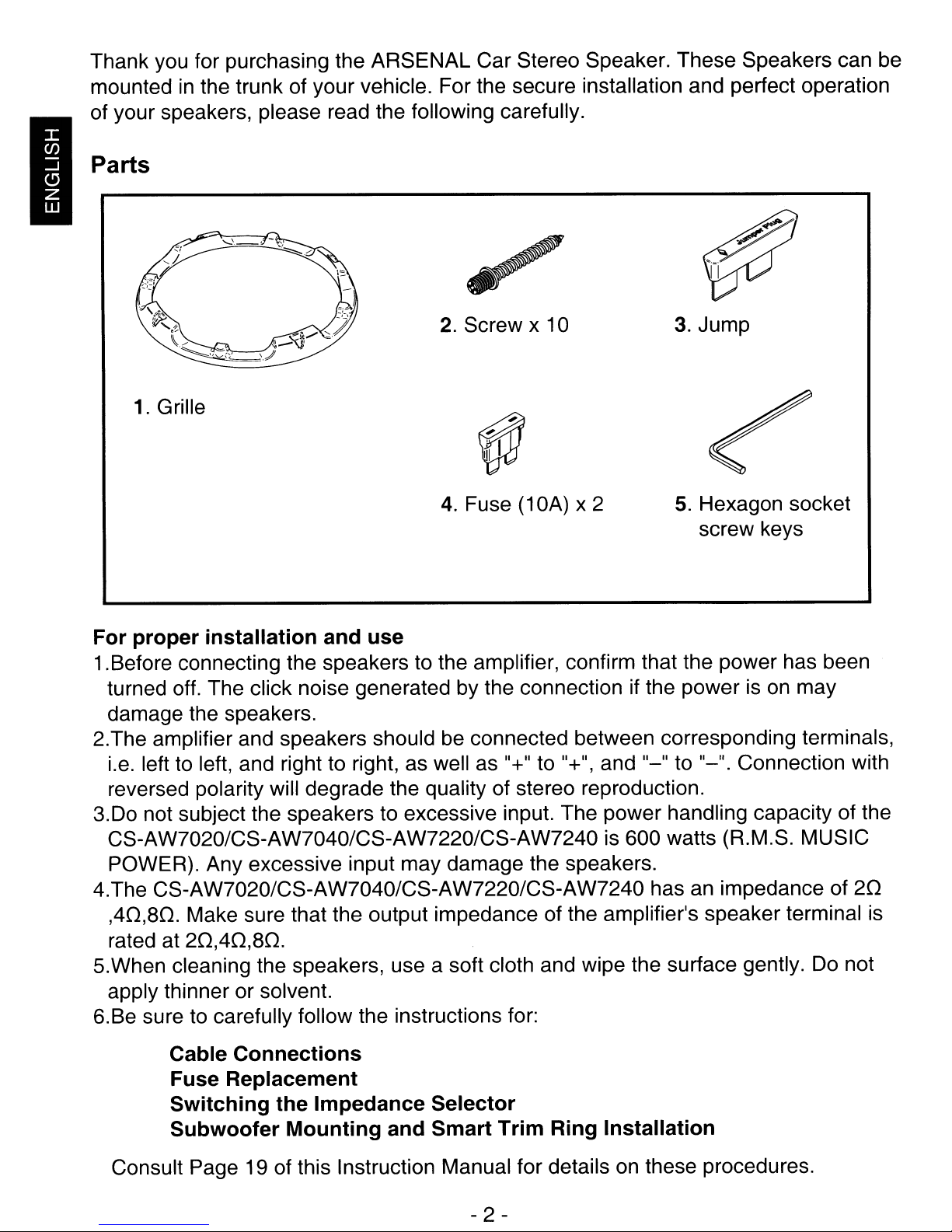
Parts
3.
Jump
1.
Grille
2.
Screw x 10
~
4.
Fuse (10A) x 2
5.
Hexagon socket
screw keys
For proper installation and use
1.Before connecting the speakers to the amplifier, confirm that the power has been
turned off. The click noise generated by the connection if the power is
damage the speakers.
2.The amplifier and speakers should be connected between corresponding terminals,
i.e. left to left, and right to right, as well as
reversed polarity will degrade the quality of stereo reproduction.
3.Do not subject the speakers to excessive input. The power handling capacity of the
CS-AW7020/CS-AW7040/CS-AW7220/CS-AW7240
POWER). Any excessive input may damage the speakers.
4.The CS-AW7020/CS-AW7040/CS-AW7220/CS-AW7240 has
,40,80.
rated at
5.When cleaning the speakers, use a soft cloth and wipe the surface gently.
apply thinner or solvent.
6.Be sure to carefully follow the instructions for:
Make sure that the output impedance of the amplifier's speaker terminal
20,40,80.
Cable Connections
Fuse Replacement
Switching the Impedance Selector
Subwoofer Mounting and Smart Trim Ring Installation
"+" to "+", and "_" to "_". Connection with
is
600 watts (R.M.S. MUSIC
an
impedance of
on
may
Do
20
is
not
Consult Page 19 of this Instruction Manual for details
- 2 -
on
these procedures.
Page 3
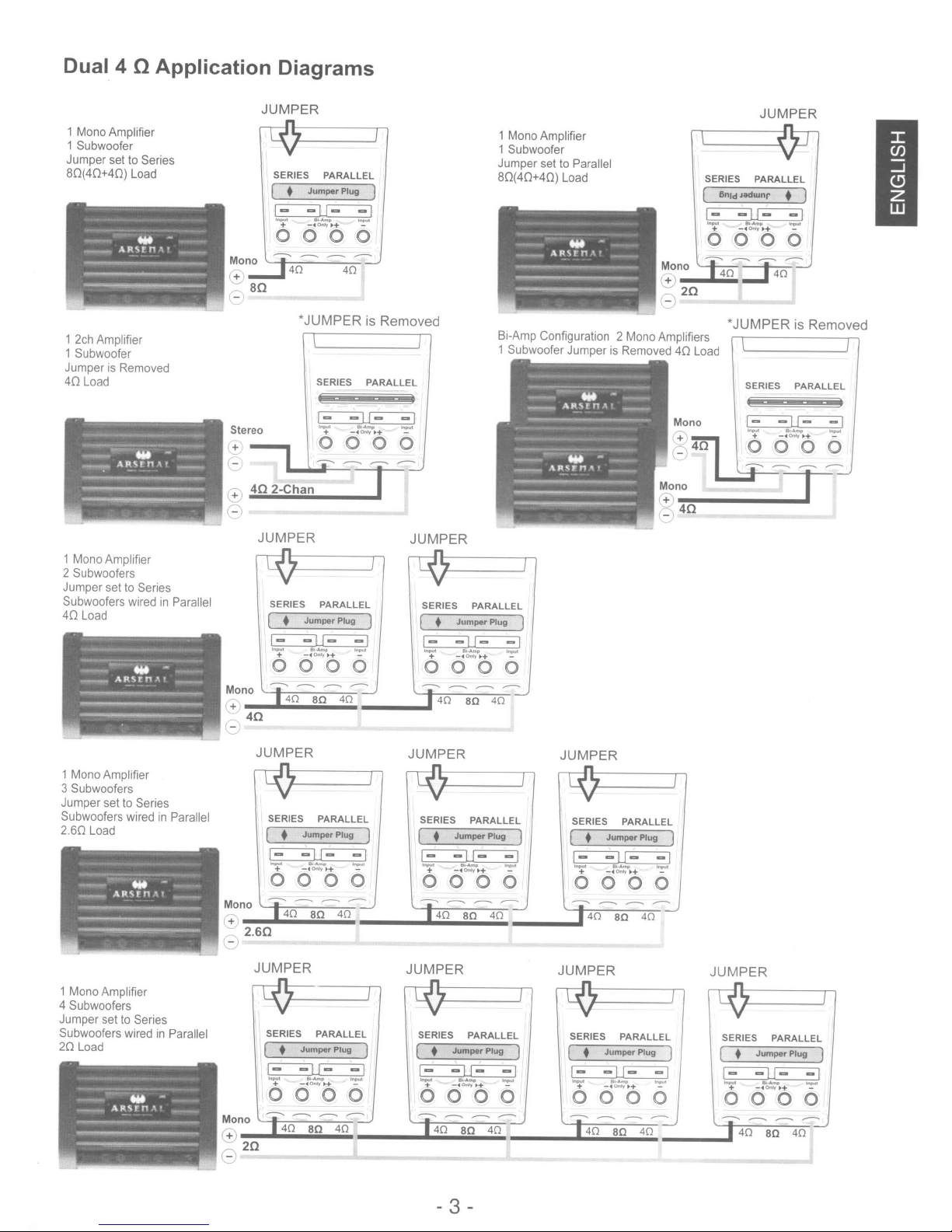
Dual 4 nApplication Diagrams
1 Mono Amplifier
1 Subwoofer
Jumper set to Series
80(40+40)
1 2ch Amplifier
1 Subwoofer
Jumper
40
1 Mono Amplifier
2 Subwoofers
Jumper set to Series
Subwoofers wired
40
Load
Load
Load
is
Removed
in
Parallel
JUMPER
SERIES
[ •
E3~
PARALLEL
Jumper
Plug
1
lnP"!
Bi
.......p
-+
-4OnIJ.+
InfWI
-
o 0 0 0
Mono
(!:.,
Stereo
-+
'+
Mono
(+
40
40
ao
*JUMPER is Removed
SERIES
E3~
.....
+ -
PARALLEL
......
..
Onty.+
o 0 0 0
402-Chan
JUMPER JUMPER
SERIES
[ •
__
40
PARALLEL
Jumper
Plug
1
a.;,;,40;,;.,.;;a~0:..4;,;0~
...
-
SERIES
[ •
E3~
+ -40ntJ.+ -
-
000
--
..
40
1 Mono Amplifier
1 Subwoofer
Jumper set
80(40+40)
Bi-Amp Configuration 2 Mono Amplifiers
1 Subwoofer Jumper
PARALLEL
Jumper
Plug
.......
-
to
Parallel
Load
1
0
---..
--
--
aD
40
is
Removed40Load
~_r
40
JUMPER
SERIES
(
~
-
PARALLEL
enid
Jodwnr
• 1
+
-40n1y..
........
-
-
0000
*JUMPERisRemoved
SERIES
PARALLEL
1 Mono Amplifier
3 Subwoofers
Jumper set
Subwoofers wired
2.60
1 MonoAmplifier
4 Subwoofers
Jumper set to Series
Subwoofers wired in Parallel
20
Load
Load
to
Series
in
Parallel
JUMPER
Mono
SERIES
[ •
E3~
Inpul 80..........
PARALLEL
Jumper
Plug)
+ -40n1y.+ -
o 0 0 0
--
--
--
In"'"
--
JUMPER JUMPER
SERIES
( •
E3E3
~
PARALLEL
Jumper
Plug
)
81·
......
-+
-40rl1y.+
Input
-
o 0 0 0
--
--..
--
--
JUMPER JUMPER JUMPER
Mono
CB
20
SERIES
( •
E3~
PARALLEL
Jumper
Plug
Input Bi-Amp Inpul
+ -
..
Only..
000
-------
40
aD
40
SERIES
1
-
0
( •
E3E3
Input
0000
------
± -
PARALLEL
Jumper
80...-.-
..
Only..
Plug
I<lIl<II
-
1
8
SERIES
[ •
~
InpuI
o
PARALLEL
Jumper
Plug
1lt-A"'tI
+ -40ntJ.+ -
000
-------
SERIES
[ •
~E3
Input
o 0 0 0
+ _
PARALLEL
Jumper
8/..,.
...
..
Only.+
Plug
p
--------
IRl>uI
IRl>uI
1
JUMPER
SERIES
1
_
[ •
~
Input
+ -
PARALLEL
Jumper
III
.........
..
Only..
Plug
1
~
-
0000
-------
- 3 -
Page 4

Dual 2 n
Application
Diagrams
1 Mono Amplifier
1 Subwoofer
Jumper set to Series
40(20+20)
1
2ch
Load
Amplifier
1 Subwoofer
Jumper
is
20
1 Mono Amplifier
2 Subwoofers
Jumper set to Series
Subwoofers wired
20
Removed
Load
Load
in
Parallel
Mono
+
Stereo
+
+
40
JUMPER
SERIES
( •
~
.....
...
0000
--
20
202-Chan
JUMPER
SERIES
( •
~~
.....
+ -40..t,0,,+ -
000
--
PARALLEL
Jumper
---
-<IIONr.-+
-- --
*
JUMPER
SERIES
~~
Input
...-..
0000
PARALLEL
Jumper
"'-
--.
--
PlUg)
.....
-
,--
20
is Removed
PARALLEL
........
p
Only".
Plug)
.....
0
----
-.ut
-
JUMPER
SERIES
( •
~
.....
...
0000
--
1 Mono Amplifier
1 Subwoofer
Jumper set to Parallel
40(20+20)
Bi-Amp Configuration 2 Mono Amplifiers
Load
1 Subwoofer Jumper
PARALLEL
Jumper
PlUg)
---
--
.....
-
---
-40n1yt>+
--
10
is
Removed20Load
Mono
+
~_T
20
JUMPER
SERIES
(
E3.E3
InpuI
PARALLEL
6nld
Jodwnr
8l~
...
-4Onfyt>+
o 0 0 0
*JUMPER
SERIES
~~
Input
...
0000
• )
......
-
is Removed
PARALLEL
81
....
"'..
- ..
Only
1>.
1n",,1
-
1 Mono Amplifier
3 Subwoofers
Jumper set to Series
Subwoofers wired
1.30
Load
1 Mono Amplifier
4 Subwoofers
Jumper set to Series
Subwoofers wired
10
Load
in
Parallel
in
Parallel
JUMPER
SERIES
( •
~F3
~
+
o 0 0 0
--------
+
JUMPER
SERIES
( •
~
"-
+ -
0000
-----
(-
PARALLEL
Jumper
81
.......
-.0nIy".
PARALLEL
Jumper
.~
..
Onfy".
Plug)
PlUg)
ktpuI
-
.......
-
JUMPER
SERIES
( •
~F3
Input
PARALLEL
Jumper
...........
+
-4Onfyt>+
o 0 0 0
------
JUMPER
SERIES
( •
~~
..................
PARALLEL
Jumper
+
-4ewy
1>+
0000
--------
Plug)
Plug)
JUMPER
SERIES
( •
Input
-
~~
Input
000
+
PARALLEL
Jumper
Plug)
81·......' 1n""1
-40n1y,,+
-
0
------
JUMPER
SERIES
( •
-
~E3
PARALLEL
Jumper
PlUg)
InpuI
81"'-
-+
-.entrl>.
InpuI
-
0000
JUMPER
SERIES
( •
~
Inpul
...-..
000
PARALLEL
Jumper
til.......
On/J..
PlUg)
Inpul
-
0
- 4 -
Page 5

• To install the sealed enclosure
When the speaker cannot be attached in the car, make the sealed enclosureasrecommended in
recommended for the enclosure materials.
Front
& Rear Baffle
Boards
(x 2)
CS-AW7020 / CS-AW7040 CS-AW7220 / CS-AW7240
15-13/32
A
15-13/32
B
11-13/32
C
9-4/32
9-23/32
4/32
inch(3mm)
1.57
ft3
inch (232 mm)
inch (247 mm)
(0.045 m
D
E
F
G
the
inch (391.7 mm)
inch (391.7 mm)
inch (290.1 mm)
3
)
table
below-20
16-13/32
16-13/32
13-29/32
10-14/32
11-10/32
4/32
inch (3 mm)
2.17
ft3
mm
(3/4 inch) MDFisalso
inch (417.1 mm)
inch (417.1 mm)
inch (353.6 mm)
inch (275.9 mm)
inch (295 mm)
3
(0.062 m
)
"Screw: Dia.
4mm
x 50mm(x8)
(supplied)
• To install the ported enclosure
When the speaker
recommended
Front
& Rear Baffle
cannot
for
be attached in the
the enclosure materials.
Boards
(x 2)
~
~
car,
make the sealed enclosureasrecommended in the table
15-13/32
A
18-13/32
B
13-13/32
C
9-23/32
D
9-23/32
E
4/32
F
G 1 inch (25.4 mm)
13
H
I
13-19/32
J
1.85
inch (391.7 mm)
inch (467.9 mm)
inch (340.9 mm)
inch (247 mm)
inch (247 mm)
inch (3 mm)
inch (330.2 mm)
inch (345.4 mm)
ft3
<0.052
3
m
)
Top&Bottom
G : Internal
Left&Right
Sides (x 2)
Volume
Sides (x
2)
r;i;.E
l'~~)::uot;og
...............
:/
Dimension
below-20
CS-AW7220 / CS-AW7240CS-AW7020 / CS-AW7040
15-13/32
18-13/32
15-13/32
10-14/32
11-10/32
4/32
1 inch (25.4 mm)
14
inch (355.6 mm)
13-6/32
mm
inch (391.7 mm)
inch (467.9 mm)
inch (391.7 mm)
inch
inch (295 mm)
inch(3mm)
inch
(3353
(3/4 inch)
(2759
Hoi'
MDFisalso
mm)
mm)
" Screw: Dia.
4mm
x 50mm(x8)
(supplied)
c
~
A
G
- 5-
: Internal
Left&Right
.pD
r
,
? Dimension
..............
Volume
Sides (x 2)
Mounting
Hole
Page 6
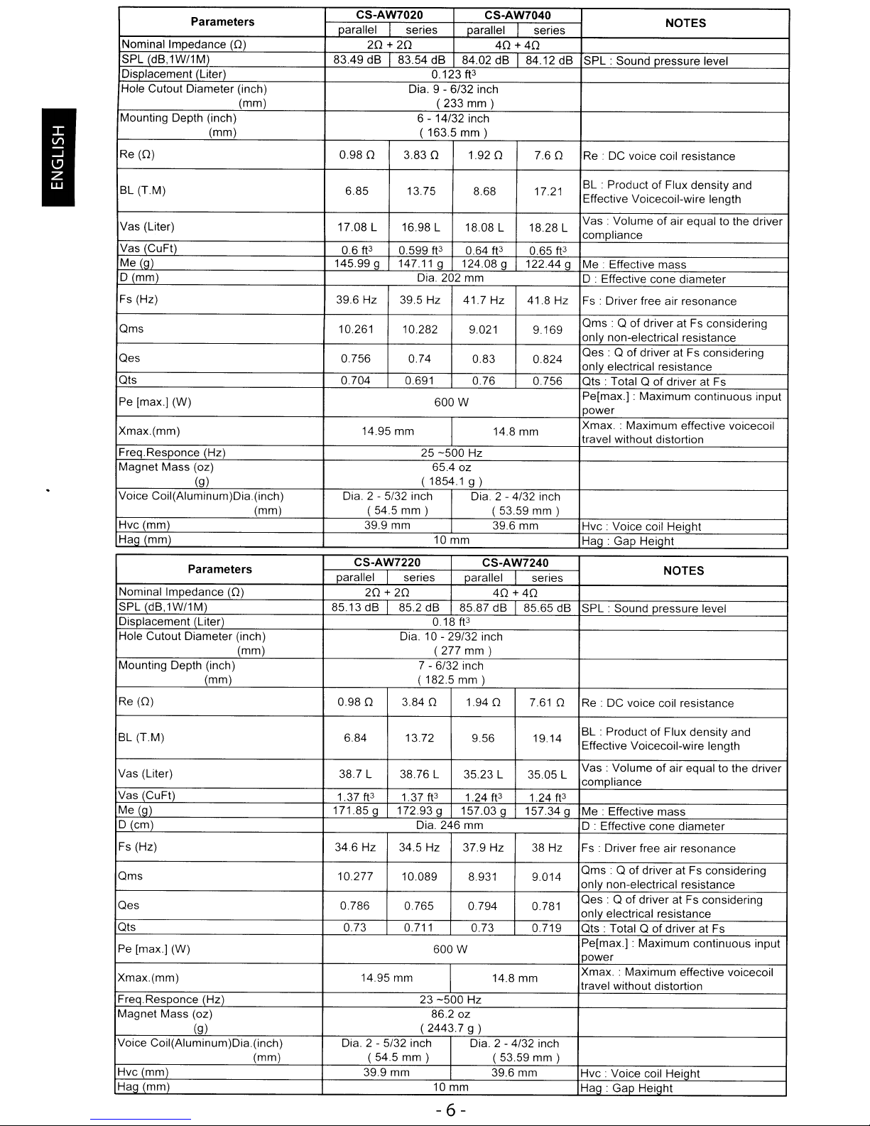
Parameters
Nominal Impedance
SPL (dB,1W/1M) 83.49
Displacement (Liter)
Hole Cutout Diameter (inch)
Mounting Depth (inch)
Re(O)
BL (T.M) 6.85 13.75 8.68 17.21
Vas (Liter)
Vas (CuFt)
Me (g)
D(mm}
Fs (Hz)
Qms
Qes
Qts
Pe [max.] (W)
Xmax.(mm}
Freq.Responce (Hz)
Magnet Mass (oz)
Voice Coil(Aluminum)Dia.(inch}
Hvc (mm)
Hag (mm)
(0)
(mm)
(mm)
(g)
(mm)
Parameters
Nominal Impedance (O)
SPL (dB,1W/1M) 85.13 dB 85.2 dB 85.87 dB 85.65 dB SPL : Sound pressure level
Displacement (Liter)
Hole Cutout Diameter (inch)
(mm)
Mounting Depth (inch)
Re (O)
(mm)
CS-AW7020 CS-AW7040
parallel
0.980
1708
ft3
0.6
145.99 g 147.11 g 124.08 g 122.44 9 Me :
39.6 Hz 39.5 Hz 41.7
10.261 10.282
0.756
0.704 0.691
14.95
Dia.
series
20+20
dB
83.54 dB
Dia. 9 - 6/32 inch
6 - 14/32 inch
( 163.5
3.830
L
16.98L
0.599
Dia. 202 mm
0.74
mm
25
( 1854.1
2 -
5/32 inch Dia. 2 - 4/32 inch
(54.5
mm)
39.9 mm 39.6 mm Hvc : Voice coil Height
parallel
8402
ft3
0.123
(233
mm)
mm)
1.920
18.08 L 18.28 L
0.64
ft3
9021
0.83
0.76
600W
-500
Hz
65.4 oz
g)
10 mm
series
40
+40
dB
84.12 dB
7.60
ft3
0.65
Hz
41.8 Hz Fs : Driver free air resonance
9.169
0824
0.756 Qts : Total Q
14.8 mm
(53.59
mm)
SPL:
Sound pressure level
Re:
DC voice coil resistance
BL . Product
Effective Voicecoil-wire length
Vas:
Volumeofair equal to the driver
compliance
ft3
Effective mass
D : Effective cone diameter
Qms:
Q of driver at Fs considering
only non-electrical resistance
Qes : Q of driver at Fs considering
only electrical resistance
Pe[max.] : Maximum continuous input
power
Xmax. : Maximum
travel without distortion
Hag:
Gap Height
CS-AW7220 CS-AW7240
parallel series parallel series
0.980
20+20
Dia. 10 - 29/32 inch
7 ( 182.5
3.840
0.18
(277
6/32 inch
ft3
mm)
mm)
1.940
40+40
7.610
Re:
DC voice coil resistance
NOTES
of
Flux density and
of
driver at Fs
effective voicecoil
NOTES
BL (T.M)
Vas (Liter) 38.7 L 38.76 L
Vas (CuFt)
Me (g)
D(cm)
Fs (Hz)
Qms
Qes
Qts
Pe [max.] (W)
Xmax.(mm)
Freq.Responce (Hz)
Magnet Mass (oz)
(g)
Voice Coil(Aluminum)Dia.(inch)
(mm)
Hvc (mm) 39.9 mm
Hag (mm)
6.84 13.72 9.56 19.14
35.23 L
ft3
1.37
171.85 g
34.6
Hz
10.277
0.786 0.765
0.73
14.95 mm
2 - 5/32 inch Dia. 2 - 4/32 inch
Dia.
(54.5
3
1.37ft
172.93 g 157.03 g
Dia. 246 mm D : Effective cone diameter
34.5 Hz 37.9 Hz
10089
0.711 0.73 0.719 Qts : Total Q
23
(2443.7
mm)
1.24
8.931
0.794 0.781
600W
-500
Hz
86.2oz
g)
10 mm
3505
ft3
157.34g
14.8 mm
(53.59
39.6 mm
- 6 -
of
BL : Product
Effective Voicecoil-wire length
Vas:
L
1.24
ft3
38
Hz Fs : Driver free air resonance
9.014
mm)
Volume of air equal to the driver
compliance
Me : Effective mass
Qms
: Q of driver at Fs considering
only non-electrical resistance
Qes : Q
only electrical resistance
Pe[max.] : Maximum continuous input
power
Xmax. : Maximum
travel without distortion
Hvc : Voice coil Height
Hag:
Gap Height
Flux density and
of
driver at Fs considering
of
driver at Fs
effective voicecoil
Page 7
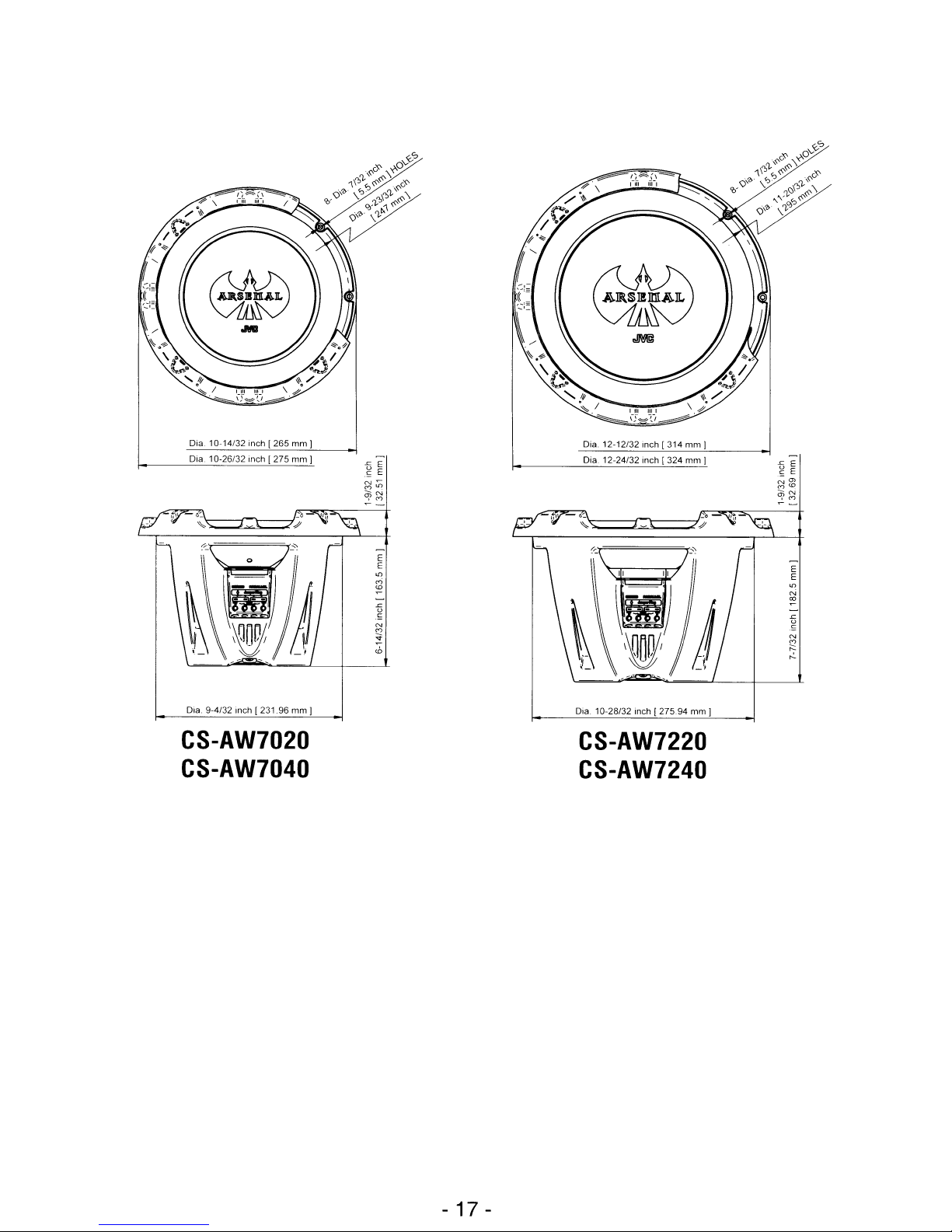
Dia. 10-14/32 inch
Dia. 10-26/32 inch
1265
1275
mm
mm
J
J
E
E
-
E
E
'"
M
~
~
-5
.'=
~
~
<D
Dra. 12-12/32 inch
Dia 12-24/32 inch
1314
(324
mm
mm
J
J
-
E
E
m
<0
~
-
"'
N
~
-
~
N
<'">
E
E
~
Dia. 9-4/32 inch
1231.96
mm
CS-AW7020
CS-AW7040
J
Dia. 10-26/32 inch
1275.94
mm I
CS-AW7220
CS-AW7240
- 17 -
Page 8
[
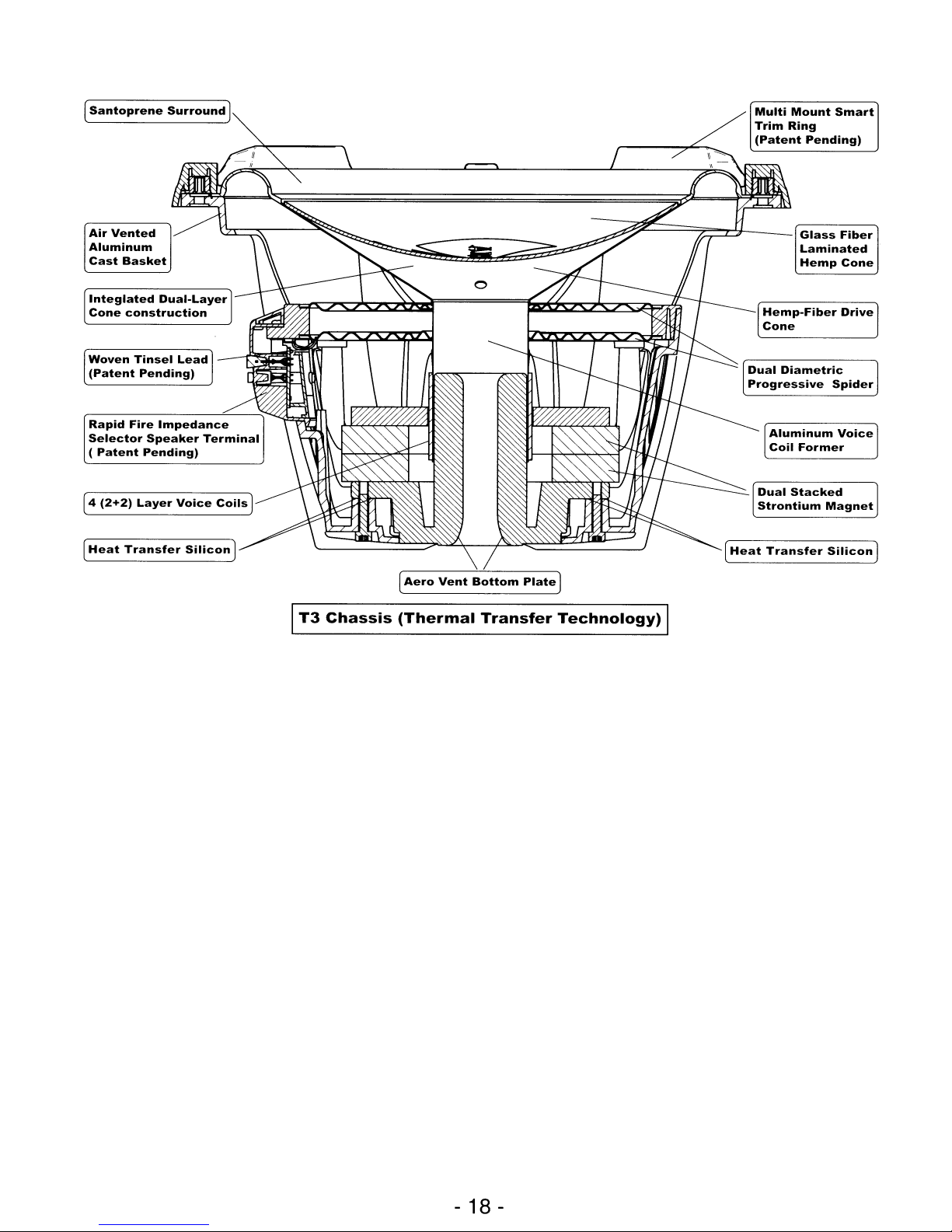
Santoprene
Surround
Multi
Mount
1
Trim
Ring
(Patent
Smart
Pending)
Air
Vented
Aluminum
Cast
Integlated
Cone
Woven
(Patent
Rapid
Selector
(
Patent
[4
(2+2)
[
Heat
Basket
Dual-Layer
construction
Tinsel
Pending)
Fire
Impedance
Speaker
Pending)
Layer
Transfer
Lead
Voice
Silicon
Terminal
Coils
1
--=~~~==='7=-rlJ---_J
Glass
Laminated
Hemp
Aluminum
Coil
Former
Fiber
Cone
Voice
1
[
Aero
Vent
T3
Chassis
Bottom
(Thermal
Plate
Transfer
1
Technology)
- 18 -
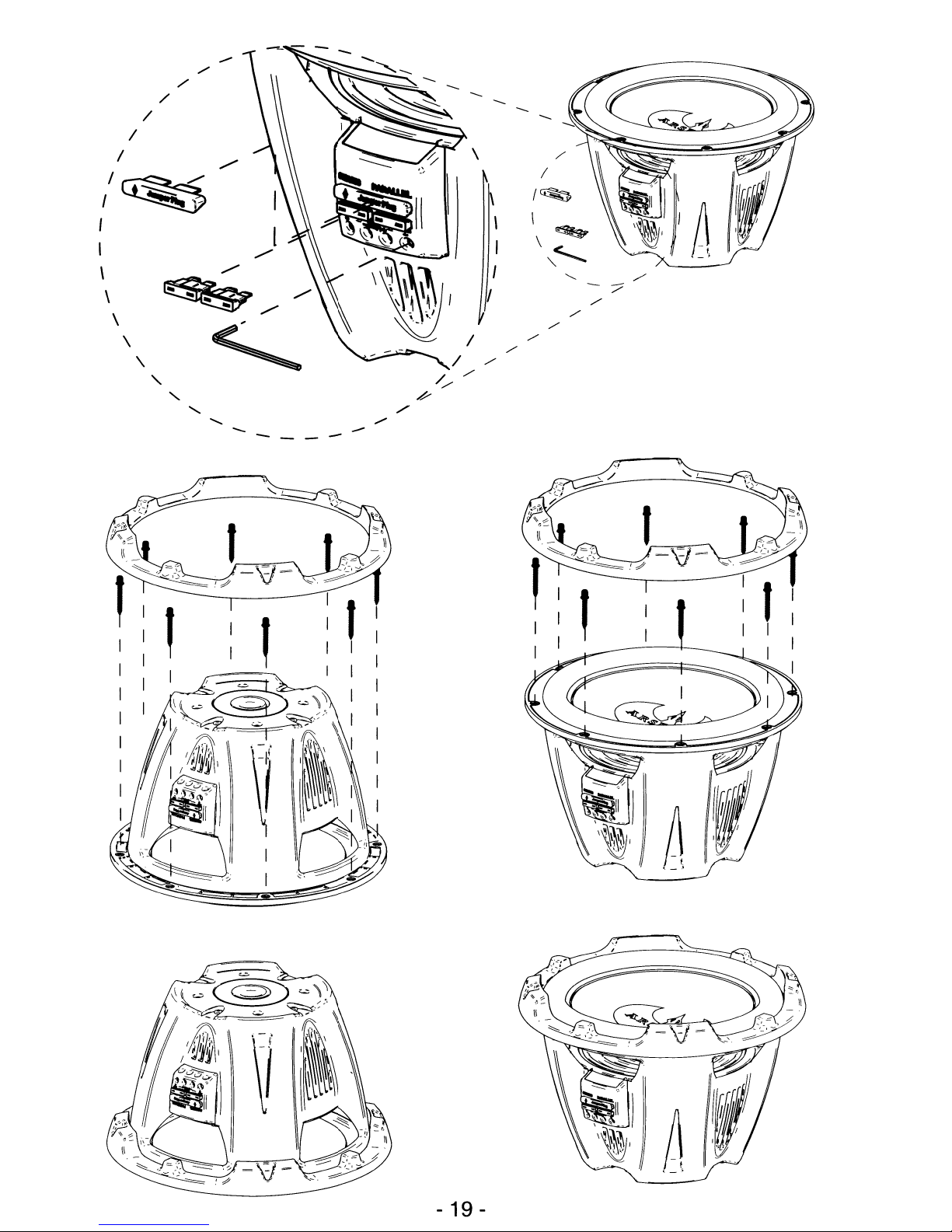
Page 9
/
/
/~
I
,
I
\
\
\
\
/
/
/
~~-
~
\.
"
"'-
,/
"-
-
.......
.......
...
~
.........
--
.......
--
"
.......
--
--
--
--
--
\
I
I
I
/
,/
/'
/
/'
/,/
.v
./
.-
-
"-
/'
/'
/'
-?
./
,/
- 19 -
Page 10

TO
OUR VALUED CUSTOMER
--
THANK
YOU
FOR PURCHASING THIS JVC PRODUCT.
WE WANT TO HELP YOU ACHIEVE A PERFECT EXPERIENCE.
NEED HELP ON HOWTO HOOK UP?
NEED ASSISTANCE ON HOWTO OPERATE?
NEEDTO LOCATE A JVC SERVICE CENTER?
LIKE TO PURCHASE ACCESSORIES?
JVC®IS
HERETO
HELP!
TOLL FREE: 1(800)252-5722
Remember
---
http://www.jvc.com
to
retain
Do not attempt to service the product yourself
Caution
To
There
Please
your
prevent
are
refertoqualified
BillofSale
electrical
no
user
for
Warranty
shock,
serviceable
do
service
Service.
not
open
parts
inside.
personnel
the
for
cabinet.
repairs.
@
EN,
FR,
SP
© 2007 Victor Company of Japan, Limited
PrintedinChina
Page 11
Instructions
Foldsoopeningisat
Tapeinmiddleoron
Thank
the
top.
front.
you
for
purchasing
Pleasedonot
correspondencetothis
JVC
1700
Wayne,NJ07470
307C
send
AMERICAS
Valley
Road
productsorother
CORP
PRODUCT
address.
JVC®
PO BOX 9580
PEORIA IL 61612-9580
1.11
•••••
11.11
•••••11••
REGISTRATION
PLACE
FIRST-CLASS
STAMP
HERE
11
1.11.1
IIIII
•••
1.1.1••1.11
•••1••
1.11
••••1••
CARD/QUESTIONNAIRE
Registering
event
This
this
a product
formisfor
form
THANK
your
does
not
YOU
REGISTER
I
product
safety
Product
diminish
FOR
ONLINE
us
CUSTOMERS
will
allowusto
notificationisrequired.
Registration
your
rights
PURCHASING
AT:
ONLY
purposes
during
THIS
WWW.JVC.COM
contact
only.
the
JVC
I
youinthe
Failuretoreturn
warranty
PRODUCT
unlikely
period.
Page 12

JVC"
Product Registration
First Name:
Last Name:
Address:
Apt#"
City:
State:
Zip:
Phone:
Email Address:
Thank you! We appreciate your responses to this questionnaire.
The information you choose to share with us will be used by JVC to offer you
product information and other communications that may interest you.
If you prefer not to be contacted about these special offers, please check here. { }
Date of Purchase
Model Number
Serial Number
Purchase Price
Dealer
IMPORTANT: Please fill-out and return
10 days or Log to JVC.com
and register On-Line
in
1) Did you:
- Purchase this product your self?
- Receive this product as a gift?
2) Is this Product:
- The first product of this type you have ever owned?
- A replacement for a similar JVC product?
- A replacement for a similar product made by another
company?
-
An
additiontoa similar product you are still using?
3) What factors most influenced your
decision to purchase this product?
- JVC brand reputation
- Previous experience with JVC products
- Price
-
Specific
product
- Style/appearance
• Salesperson's recommendation
- Friend/relative's recommendation
- Warranty coverage
- Other
features
4) How did you learn about this product?
- Magazine Advertisement
- Newspaper Advertisement
- TV/Radio Announcement
- Product Brochure
- Direct Mail
- Mail Order Catalog
- Friend/Relative Recommendations
- Salesperson/Store Recommendation
- Internet
- Dealer Event
- Other
8T-51041-1
(0406)
5)Your Gender:
- Male
• Female
6) Your Marital Status
- Married
- Single
7) What is your approximate annual
household income level?
- Under $25,000
- $25,000 - $49,000
. $50,000 - $74,000
- $75,000 - $99,000
- $100,000 and over
Comments:
JVCThanks you for completing this
questionnaire.
Your responses will help us reach you with
offers that
It
you prefer
may
interest you.
not
to receive these offers
please check here { }
PrintedinChina
Page 13

JVC
CANADA
INC.
(ci-apres appele
"JVC")
enonce
la
garantie expresse suivante pour tout nouveau
produit
JVC,
distribueauCanada
par
JVCetvendu
parundetaillant JVC autorise.
JVC
vous
garantit queceproduit
JVC
est degage,
sous
une
utilisationetd'entretiens
normaux,detout
defauts d'habilete professionnelleetd'articles sous
reserve des modalites et conditions suivantes:
1.
Pour obtenir un service de garantie:
(a)Lacarte garantiedecontr51e
JVC
ci-incluse
doit
contenir
les
renseignements
complets
et
etre postee d'achatduproduit
JVCoualler
surIesite
par
internet
pour
enregistrement
(7)
deladate d'achatduproduit
JVC.
(b)
Cette carte garantiedecontrole JVC doit
contenir
les
renseignements
completsetetre
presentee
aveclapreuve d'achatdeI'article
JVC pour obtenir
Ie
service.
(c)Leproduit JVC doit etre apporte chez
un
detaillant JVC autorise pourunservice
d'entretien.
2.
Restrictions:
Cette garantfenes'applique
pas
aux:
(a)
Reparation ou remplacement de tous
cabinets, batteries, panneaux avant,
cordons
de
raccord, antennes, housses
de
protection, boutons, treillis d'enceinte
accoustique, cones
de
haut-parleur, ecrans
de
projection, protecteurs d'ecrans de
projection, et tous les accessories.
(b)
Tous
defauts occasionnesoureparations
requises suite
a une utilisation abusive
ou
mauvaise,denegligence, soins insuffisants
eVou
utilisation incorecte.
(c)
Tous
defauts occasionnesoureparations
requises suite
a I'omission
de
suivre les
recommandations d'un
manuel
d'instruction.
(d)
Tou1produit
JVC touche,
ajusteourepare
par
toute autre entreprise
que
JVCouun
centre
de
service d'entretien etdereparation
autorise
JVC.
WARIANTY
GAlANT
II
JVC
CANADA
INC.
21
Finchdene Square, Toronto,ONM1X 1A7
TEL: (416) 293-1311 FAX: (416) 293-8208
http://www.jvc.ca
JVC
CANADA
INC.
(hereafter called
"JVC")
gives
the following express warranty
for
each
new
JVC
product distributedinCanadabyJVC
and
sold
by
an
authorized JVC dealer.
JVC warrants that this JVC product
is
free,
under
normal
use
and
maintenance,
from
any
defects
in
material
and
workmanship subjecttothe
following
terms
and
conditions;
1.ToObtain Warranty Service:
(a)
The JVC Warranty Control
Card
herein
provided must
be
completedinfull
and
postedorregistered
via
internet
within7days
of date of purchase of
the
JVC
product.
(b)
This
JVC
Warranty
Control
Card
must
be
completedinfUll
and
presented together
with
proof of purchase of
the
JVC
product
requiring service.
(c)
The
JVC
product mustbebroughtinfor
servicetoan
authorized
JVC
Service
Centre.
2. Limitation:
This
Warranty
shall
not
apply
to;
(a)
Repair or replacement of
any
cabinets,
batteries, plates, connection
cords,
anten-
nas,
dust covers, knobs, speaker grills,
speaker
cones,
projection
screens,
projection
screen
savers,
and
all accessories.
(b)
Any
defects
causedorrepairs
requiredasa
result
of
misuse,
abusive operation, negli-
gence,
improper
use
and/or
insufficient
care.
(c)
Any
defect caused or repairs requiredasa
resultofnot
following
the
instructionsinthe
operation
manual.
(d)
Any
JVC product tampered
with,
adjusted
or repaired
by
any
party other
than
JVC
or
authorized
JVC
Service Centre personnel.
PRINTEDINCHINA
P
·oslal·Cocle······
Code
Postal
Street
Rue
Apt.
App.
....
·PosliJfCod's
..
Code
Postal
il
decouper
ici
Code
Postal
Vous
pouvez
egalement
vous
inscrire
par
internet
a:www.ivc.ca
Rue
Street
Rue
Provo
Provo
PrOVo
Provo
Provo
Provo
..............
"·Prov.·
·posi.i·Code
Provo
Code
Postal
Detach
here.
JVC
No
You
may
also
register
on-line
at:www.ivc.ca
CANADA
ONLY
City
or
Town
Ville
Owner's Name
Nom du Proprietaire' ,.. ,_... . .. . ...•. . .
................•
Owner's Address
Adresse
du
Proprietaire'
,.......
. . ..
No.
Street
No
Rue
City orTown
Ville
WARRANTY CONTROL CARD
IWARRANTY
APPLIES
ONLYTOPROOUCT
CARTEDECONTROlEDElA
GARANTIEDISTRIBUTEOINCANADA
BY
JV:
CANADA
INC.
IMPORTANT:
This
warranty
control
card
mustbefilledinand
postedtothe
address
indicated
on
the
back
hereoforregister
via
internet
within7(seven)
days
from
the
dateofpurchase.
IMPORTANT:
Cette
carte
doit
etre
renvoyee
dOment
remplieaI'adresse
indiquee
all
verso,
dans
les7joursdela
date
d'achatoualler
surIesite
par
internet
pour
enregistremeill.
(PLEASE
PRINT/EN
LETTERS
MOULEES)
MOO~L
SERIAL
NO.
.
MODELE NO
DE
SERlE'
. .. ..
Purchased from . Date purchased .
Achete
chez
Date
achete
.. ..
Dealer's Address
Adresse
du
Vendeur...........• .......•
..
-...............•..................••...
11.1"
e-••__
•
OWNER'S COPY OF WARRANTY CARD
COPIE D'ENREGISTREMENTDElA
GARANTIE
DU
PROPRIETAIRE
(Save
sales
docket
together
with
this
warranty
card,asa
proofofdateofpurchase.
La
factureetcette
grantie
sont
vas
preuvesdela
date
d'achat;
rangez-Ies.)
MODEL.
C~-AW7()"n
SERIAL
NO.
MODELE'
:.~
NODESERlE'
.
Purchase
from.
Date
purchased.
Achete
chez
.
Date
achete
:
..
Dealer's
Address
.
AdresseduVendeur'
..
No.
No
cii¥orTowii'
Vilre
Owner's
Name
.
NomduProprietaire:
...
Owner's
Address
AdresseduProprietaire'
.
No.
No
cii¥'orTowii"
Vilre
8T-52006-2
(1002)
Page 14
WARRANTYTERM (VALID FROM THE DATE OF PURCHASE)
CONDITIONS DE GARANTIE (VALABLE
aPARTIR DE
LA
DATE D'ACHAT)
PRODUCT
PARTS
(Years) Labour (Years)
PROOUIT
PIECES
(annees)
MAIN-D'OEUVER
(annees)
ProjectionlTVs,
ProjectionlTV In-Home Service
(25" and
above)
Telewiseurs couleurs, ecransdeprojection
Service
it domicile pour ecrans
de
projection couleur (25"etplus)
TV
VCR
Combo
1 1
TV
VCR
Comb
D-ILA
Rear
Projection
TV
TV
projection
arriE'He
D-ILA
In-Home service
tobeprovided where
available.
• Where itisnot available,
the
Purchaser
must
assume
the
responsibility and expense for the proper
packing, shipment,
and
all
costs associated
with
the
deliveryofthe
equipmenttoand
from
the closest
JVC
Authorized Service Centre.
Service a domicile fourni par
un
detaillant disponible.
•
S'il
n'y it
pasdeservice
JVC
disponible a
proximite,
I'acheteur
doit
assumerlaresponsabiliteetles
coOts
pour
un
emballage adequant, lexpedition, ainsi que tous les
coOts
associes itlalivraisondeI'equipment par
et
depuisIedetaillant JVC auto
rise
pourunService d'entretien.
Receivers, Home Speaker Systems, Car
Audio
"digifine"
and
"ARSENAL.:'
series
2 2
Recepteurs, systemesdehaut-parleur maison,
Audio
D'auto des
series "digifine"
et
"ARSENAL.:'
AC
Adapters, Remote Controls, Headphones, Microphones
90
days
90
days
Adaptateurs
AC,
telecommande, casque d'ecoute, microphones,
90
jours
90
jours
piles
Lamp Warranty
For
Consumer
Use
1
1
Garantie
delalampe pour utilisationdeconsommateur
Lamp Warranty
For
Commercial
Use
90
days
90
days
Garantie
delalampe pour utilisationdecommerciale
90
jours
90
jours
All
Other Categories
1
1
Toutes
les autres categories
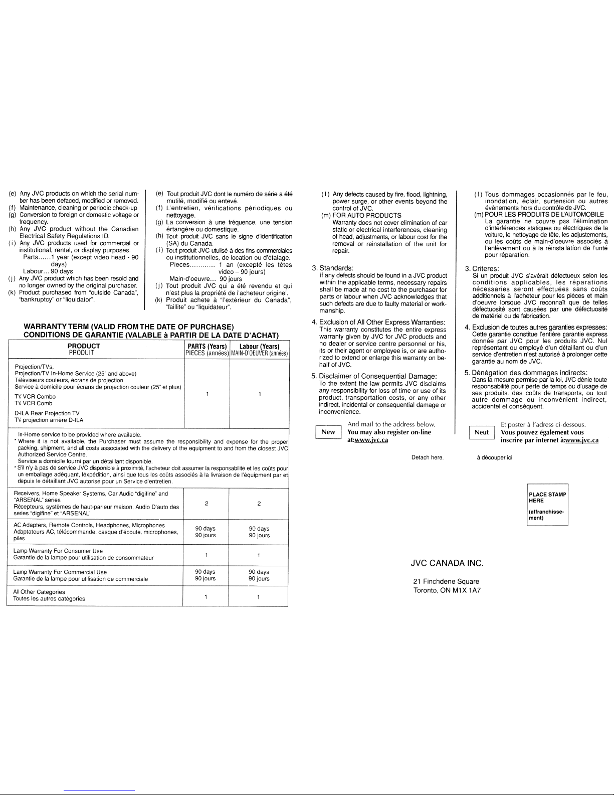
JVC CANADA INC.
21
Finchdene
Square
Toronto,ONM1
X 1A7
(
I)
Tous
dommages
occasionnes
par
Ie feu,
inondation,
eclair,
surtensionouautres
evenements hors du contrale de JVC.
(m) POUR LES PRODUITS
DE
L.:AUTOMOBILE
La garantie ne couvre
pas
I'elimination
d'interferences statiques
ou
electriques de
la
voiture,Ienettoyage de tete, les adjustements,
au les coOts de main-d'oeuvre associes
a
I'enlevement au ala reinstallation de I'unte
pour reparation.
it decouper
ici
(affranchissemen!)
PLACE STAMP
HERE
Et
posteritI'adress ci-dessous.
~
Vous
pouvez
egalement vous
inscrire
par
internet
a:www.jvc.ca
3.
Criteres:
5i un produit
JVC
s'averait defectueux selon les
conditions
applicables,
les
reparations
necessaries
seront
effectuees
sans
coOts
additionnels
aI'acheteur pour les pieces et main
d'oeuvre lorsque
JVC
reconnait que de telles
defectuosite sont causees par une defectuosite
de materiel
oudefabrication.
4.
Exclusiondetoutes
autres garanties expresses:
Cette garantie constitue I'entiere garantie express
don
nee
par
JVC
pour les produits JVC. Nul
representant ou employe d'un detaillant ou d'un
service d'entretien n'est autorise
aprolonger cette
garantie au nom
de
JVC.
5.
Denegation
des
dommages
indirects:
Danslamesure permise par la loi, JVC denie toute
responsabilite pour perte de temps
ou
d'usage de
ses produits,
des
coOts de transports, ou tout
autre
dommageouinconvenient
indirect,
accidentel et consequent.
Detach
here.
(I)Any defects caused by fire, flood, lightning,
power surge, or other events beyond the
control of JVC.
(m)
FOR
AUTO PRODUCTS
Warranty does not cover elimination of car
static or electrical interferences, cleaning
of head, adjustments, or labour cost for the
removal or reinstallation of the unit for
repair.
And
mail
to the address below.
~
You may. also register
on-line
at:www.Jvc.ca
3.
Standards:
If
any defects shouldbefoundina JVC product
within the applicable terms, necessary repairs
shall be made at no cost to the purchaser for
parts or labour when
JVC
acknowledges that
such defects are duetofaulty material or workmanship.
4.
Exclusion
of
All
Other
Express
Warranties:
This warranty constitutes the entire express
warranty given by JVC for
JVC
products and
no dealer or service centre personnelorhis,
its or their agent or employee is, or are authorized to extend or enlarge this warranty on behalf of JVC.
5.
DisclaimerofConsequential
Damage:
To
the extent the law permits
JVC
disclaims
any responsibility for loss of time or use of its
product,
transportation
costs, or any
other
indirect, incidental or consequential damage or
inconvenience.
(e) Tout produit JVC dont
Ie
numerodeserie a ete
mutile, modifie ou enteve.
(f)
L'entretien,
verifications
periodiques
ou
nettoyage.
(g) La conversion a une frequence, une tension
ertangere ou domestique.
(h) Tout produit JVC sansIesigne d'identification
(SA) du Canada.
(i ) Tout produit JVC utulise ades fins commerciales
ou institutionnelles,delocation ou d'etalage.
Pieces 1 an (excepte les tetes
video - 90 jours)
Main-d'oeuvre... 90 jours
(j)
Tout produit
JVC
qui a ete revendu et qui
n'est plus la proprietedeI'acheteur originel.
(k) Produit achete a "I'exterieur
du
Canada",
"faillite" ou "Iiquidateur".
(e) Any
JVC
products on which the serial num-
ber has been defaced, modified or removed.
(f)
Maintenance, cleaning or periodic check-up
(g) Conversion to foreign or domestic voltage or
frequency.
(h) Any
JVC
product without
the
Canadian
Electrical Safety Regulations
10.
(i)Any JVC products used for commercial
or
institutional, rental, or display purposes.
Parts
......
1 year (except video head - 90
days)
Labour... 90 days
(j)
Any JVC product which has been resold and
no longer
owned
by the original purchaser.
(k) Product purchased from "outside Canada",
"bankruptcy" or "liquidator".
Page 15
* *
i
JVC®
: I
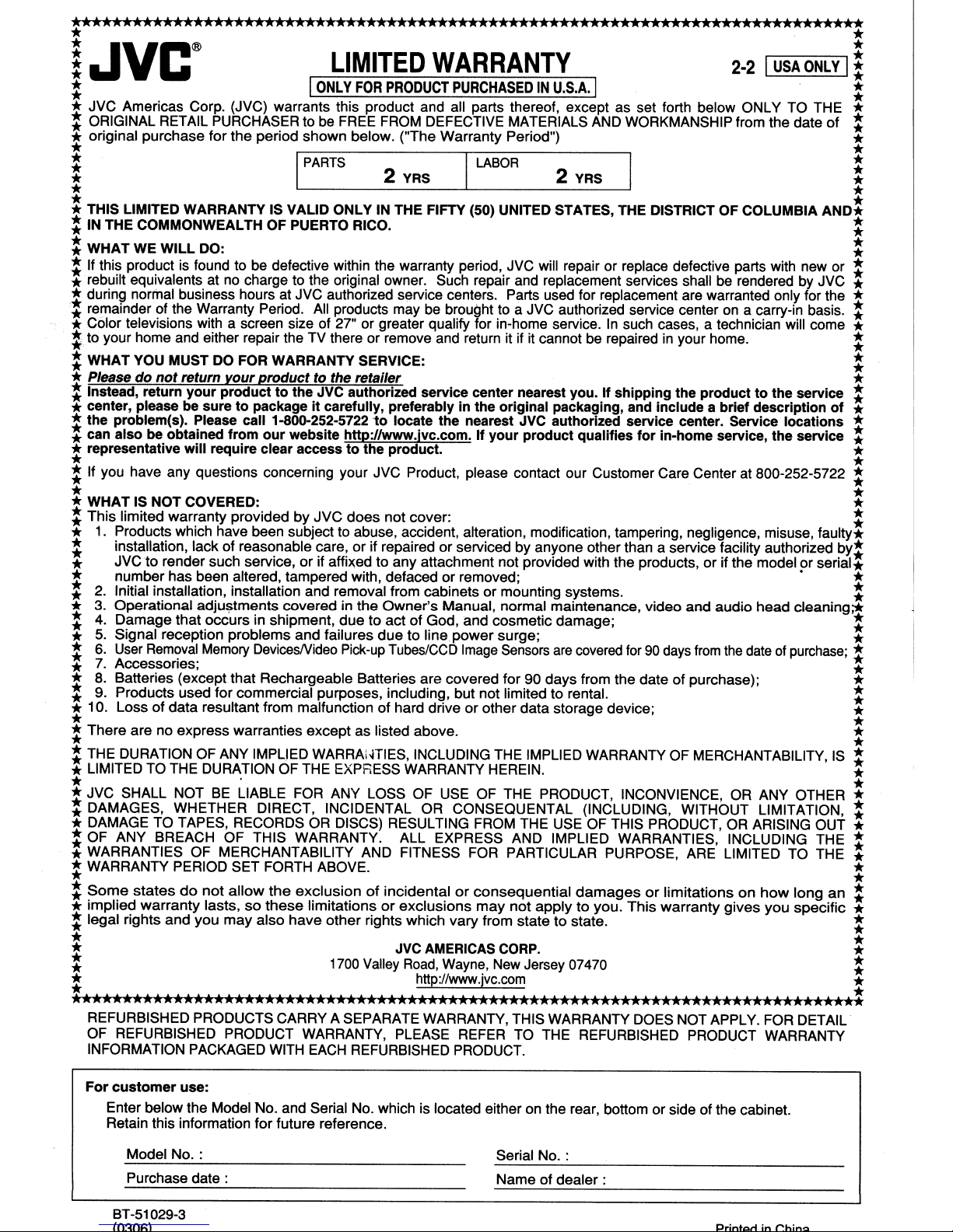
* JVC Americas Corp. (JVC) warrants this product and all parts thereof, except as set forth below ONLY TO THE *
: ORIGINAL RETAIL PURCHASER to
* original purchase for the period shown below. ("The Warranty Period") *
* *
: I
* . 2
LIMITED
ONLY
FOR
PRODUCT
be
FREE FROM DEFECTIVE MATERIALS AND WORKMANSHIP from the date of :
PARTS
WARRANTY
PURCHASEDINU.S.A.
I
YRS.
LABOR
2-2
I
I :
2 YRS *
USA
ONLY
Ii
:
! THIS LIMITED WARRANTY IS VALID ONLY IN THE FIFTY (50) UNITED STATES, THE DISTRICT OF COLUMBIA
:INTHE COMMONWEALTH OF PUERTO RICO. :
: WHAT WE WILL DO: :
: .If this product is found to be defective within the warranty period, JVC will repair or replace defective parts with new or :
* rebuilt equivalents at no charge to the original owner. Such repair and replacement services shall
: during normal business hours at JVC authorized service centers. Parts used for replacement are warranted only for the :
* remainder of the Warranty Period.
* Color televisions with a screen size of 27" or greater qualify for in-home service.
:.
to your home and either repair the TV there or remove and return it if it cannot be repairedinyour home. :
: WHAT YOU MUST
*Please
: Instead, return
do
not
*center, please
: the problem(s). Please call 1-800-252-5722tolocate the nearest JVC authorized service center. Service locations :
*can also be obtained from
DO
FOR WARRANTY SERVICE: :
return yourproduct to the retailer *
your
producttothe JVC authorized service center nearest you. If shipping the producttothe service :
be
suretopackageitcarefully, preferably in the original packaging, and Include a brief description
our
*representative will require clear access
* *
: If you have any questions concerning your JVC Product, please contact our Customer Care Center at 800-252-5722 :
* *
*
WHAT IS NOT COVERED: *
: This limited warranty provided by
*
1.
Products which have been subject to abuse, accident, alteration, modification, tampering, negligence, misuse,
: installation, lack of
*
JVCto
* number has been altered, tampered with, defaced or removed; • *
:
2.
Initial installation, installation and removal from cabinets or mounting systems. :
* 3. Operational
4.
:
5.
Signal reception problems and failures
*
:
6.
*
7.
: 8. Batteries (except that Rechargeable Batteries are covered for 90 days from the date of purchase); *
* 9. Products used for commercial purposes, including, but not limited to rental. :
* 10. Loss of data resultant from malfunction of hard driveorother data storage device; *
: There are no express warranties except as listed above. :
* *
: THE DURATION OF ANY
* LIMITED TO THE DURATION OF THE EXPRESS WARRANTY HEREIN. *
* . *
* JVC SHALL NOT
: DAMAGES, WHETHER DIRECT, INCIDENTAL OR CONSEQUENTAL (INCLUDING, WITHOUT LIMITATION, :
* DAMAGE TO TAPES, RECORDS OR DISCS) RESULTING FROM THE USE OF THIS PRODUCT, OR ARISING OUT *
* OF ANY BREACH OF THIS WARRANTY. ALL EXPRESS AND IMPLIED WARRANTIES, INCLUDING THE *
: WARRANTIES OF MERCHANTABILITY AND FITNESS FOR PARTICULAR PURPOSE, ARE LIMITED TO
: WARRANTY PERIOD SET FORTH ABOVE. :
:
Some
* implied
: legal rights and you
render such servIce, or If afftxed to any attachment not prOVided with the products, orIfthe model or
Damage that occurs in shipment, due to act of God, and cosmetic damage; :
User
Removal
Accessories; *
statesdonot
warranty
reas~nable
adju~rnents
Memory
lasts,sothese
DevicesNideo Pick-up
IMPLJED
BE
LIABLE FOR ANY LOSS OF USE OF THE PRODUCT, INCONVIENCE, OR ANY OTHER *
allow
may
also
All
products maybebrought to a JVC authorized service center on a carry-in basis. *
website http://www.lvc.com. " your product qualifies
covered in the
the
exclusionofincidentalorconsequential
have
to
the product. *
JVC
does
not cover: :
~are~
or if repaired or serviced by anyone
Owner's
due
Tubes/CCD
WARRAiHlES, INCLUDING THE IMPLIED WARRANTY OF MERCHANTABILITY,IS:
limitationsorexclusions
other rights which vary from statetostate. :
Manual, normal maintenance, video and audio
to line
power
surge; *
Image
sensors
may
are
not
applytoyou.
In
such cases, a technician will come *
for
in-home service, the service *
o~her
than a service !acility authorized
covered
damagesorlimitationsonhow
for
This
90
days
warranty
be
rendered by JVC *
head
from
the
dateofpurchase;
gives
you
AND!
of
faulty*
~Y:
senal*
cleaning;*'
THE:
longan:
specific *
*
:
*
* *
:
: http://www.jvc.com :
••••••••••••••••••••••••••••••••••••••••••••••••••••••••••••••••••••••••••••••
REFURBISHED PRODUCTS CARRY A SEPARATE WARRANTY, THIS WARRANTY DOES NOT APPLY. FOR DETAIL
OF REFURBISHED PRODUCT WARRANTY, PLEASE REFER TO THE REFURBISHED PRODUCT WARRANTY
WITH
INFORMATION PACKAGED
For
customer
Enter below the Model No. and Serial No. which is located either on the rear, bottom or side ofthe cabinet.
Retain this information for future reference.
Model
Purchase
8T-51 029-3
use:
No.:
date:
EACH
JVC
1700
Valley
REFURBISHED PRODUCT.
AMERICAS
Road,
Wayne,
CORP.
New Jersey 07470 :
Serial
No.:
Name of
dealer:
PrintcutinrhinQ
*
 Loading...