

Page 1
JLIP VIDEO CAPTURE DOCKING STATION
BASE DE MONTAGE A CAPTURE VIDEO JLIP
GV-DS1
INSTRUCTIONS
MODE D'EMPLOI
ENGLISHFRANÇAIS
For Customer Use:
Enter below the Serial No. of the
GV-DS1U JLIP VIDEO CAPTURE
DOCKING STATION.
The serial number is located on the
bottom of the JLIP VIDEO CAPTURE
DOCKING STATION.
Model No. GV-DS1U
Serial No.
LYT0002-0M1B
Page 2
2
Dear Customer,
Thank you for purchasing this VIDEO CAPTURE
DOCKING STATION. Before use, please read the
safety information and precautions contained in the
following pages to ensure safe use of this product.
SAFETY
PRECAUTIONS
Using This Instruction Manual
• All major sections and subsections are listed in the
Table Of Contents (
• Notes appear after most subsections. Be sure to read
these as well.
• Basic and advanced features/operation are separated for
easier reference.
It is recommended that you . . .
.... refer to "Controls and Connectors" (
familiarize yourself with connector locations before
use.
.... read thoroughly the Safety Precautions and Safety
Instructions that follow. They contain extremely
important information regarding the safe use of your
new VIDEO CAPTURE DOCKING STATION.
You are recommended to carefully read the cautions
on pgs. 5 and 6 before use.
Z pg. 8, 9).
Z pg. 11) and
Declaration of Conformity
Model Number : GV-DS1U
Trade Name : JVC
Responsible party : US JVC CORP.
Address : 41 Slater Drive, Elmwood Park,
Telephone Number : (201) 794–3900
This device complies with Part 15 of FCC Rules.
Operation is subject to the following two conditions:
(1) This device may not cause harmful interference, and
(2) this device must accept any interference received,
including interference that may cause undesired
operation.
Change or modifications not approved by the party
responsible for compliance could void the user's
authority to operate the equipment. This equipment has
been tested and found to comply with the limits for a
Class B digital device, pursuant to Part 15 of the FCC
Rules. These limits are designed to provide reasonable
protection against harmful interference in a residential
installation. This equipment generates, uses, and can
radiate radio frequency energy and, if not installed and
used in accordance with the instructions, may cause
harmful interference to radio communications.
However, there is no guarantee that interference will
not occur in a particular installation.
If this equipment does cause harmful interference to
radio or television reception, which can be determined
by turning the equipment off and on, the user is
encouraged to try to correct the interference by one or
more of the following measures:
Reorient or relocate the receiving antenna.
Increase the separation between the equipment and
receiver.
Connect the equipment into an outlet on a circuit
different from that to which the receiver is connected.
Consult the dealer or an experienced radio/TV
technician for help.
N. J. 07407
CAUTION:
TO REDUCE THE RISK OF FIRE,
DO NOT REMOVE COVER (OR
BACK). NO USER–SERVICEABLE
PARTS INSIDE. REFER SERVICING
TO QUALIFIED SERVICE
PERSONNEL.
WARNING:
TO PREVENT FIRE OR SHOCK
HAZARD, DO NOT EXPOSE
THIS UNIT TO RAIN OR
MOISTURE.
NOTE:
The rating plate (serial number plate) and safety
caution are on the bottom of the VIDEO CAPTURE
DOCKING STATION.
This Class B digital apparatus meets all requirements
of the Canadian Interference – Causing Equipment
Regulations.
“Cet appareil numérique de la classe B respecte toutes
les exigences du Règlement sur le matériel brouilleur
du Canada.”
When using the Video Capture Docking Station, use
the AA-V80U AC Adapter/Charger (optional or
provided with the camcorder).
Page 3
3
IMPORTANT PRODUCT
SAFETY INSTRUCTIONS
Electrical energy can perform many useful functions. But
improper use can result in potential electrical shock or
fire hazards. This product has been engineered and
manufactured to assure your personal safety. In order not
to defeat the built-in safeguards, observe the following
basic rules for its installation, use and servicing.
ATTENTION:
Follow and obey all warnings and instructions marked on
your product and its operating instructions. For your
safety, please read all the safety and operating instructions
before you operate this product and keep this manual for
future reference.
INSTALLATION
1. Grounding or Polarization
Your product may be equipped with a polarized
alternating-current line plug (a plug having one blade
wider than the other). This plug will fit into the power
outlet only one way. This is a safety feature.
If you are unable to insert the plug fully into the outlet, try
reversing the plug. If the plug should still fail to fit,
contact your electrician to replace your obsolete outlet.
Do not defeat the safety purpose of the polarized plug.
2. Power Sources
Operate your product only from the type of power source
indicated on the marking label. If you are not sure of the
type of power supply to your home, consult your product
dealer or local power company. If your product is
intended to operate from battery power, or other sources,
refer to the operating instructions.
3. Overloading
Do not overload wall outlets, extension cords, or integral
convenience receptacles as this can result in a risk of fire
or electric shock.
4. Power Cord Protection
Power supply cords should be routed so that they are not
likely to be walked on or pinched by items placed upon
or against them, paying particular attention to cords at
plugs, convenience receptacles, and the point where they
exit from the product.
5. Ventilation
Slots and openings in the cabinet are provided for
ventilation. To ensure reliable operation of the product
and to protect it from overheating, these openings must
not be blocked or covered.
• Do not block the openings by placing the product on a
bed, sofa, rug or other similar surface.
• Do not place the product in a built-in installation such
as a bookcase or rack unless proper ventilation is
provided or the manufacturer’s instructions have been
adhered to.
6. Wall or Ceiling Mounting
The product should be mounted to a wall or ceiling only
as recommended by the manufacturer.
ANTENNA INSTALLATION
INSTRUCTIONS
1. Outdoor Antenna Grounding
If an outside antenna or cable system is connected to the
product, be sure the antenna or cable system is grounded
so as to provide some protection against voltage surges
and built-up static charges. Article 810 of the National
Electrical Code, ANSI/NFPA 70, provides information
with regard to proper grounding of the mast and
supporting structure, grounding of the lead-in wire to an
antenna discharge unit, size of grounding conductors,
location of antenna discharge unit, connection to
grounding electrodes, and
requirements for the grounding electrode.
2. Lightning
For added protection for this product during a lightning
storm, or when it is left unattended and unused for long
periods of time, unplug it from the wall outlet and
disconnect the antenna or cable system. This will prevent
damage to the product due to lightning and power-line
surges.
3. Power Lines
An outside antenna system should not be located in the
vicinity of overhead power lines or other electric light or
power circuits, or where it can fall into such power lines
or circuits. When installing an outside antenna system,
extreme care should be taken to keep from touching such
power lines or circuits as contact with them might be
fatal.
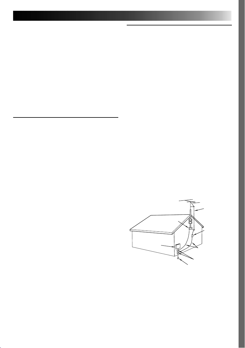
EXAMPLE OF ANTENNA GROUNDING AS PER
NATIONAL ELECTRICAL CODE, ANSI/NFPA 70
ANTENNA
LEAD IN WIRE
GROUND CLAMP
ANTENNA
DISCHARGE UNIT
(NEC SECTION
ELECTRIC SERVICE
EQUIPMENT
POWER SERVICE GROUNDING ELECTRODE SYSTEM
(NEC ART 250. PART H)
NEC – NATIONAL ELECTRICAL CODE
810-20)
GROUNDING
CONDUCTORS
(NEC SECTION 810-21)
GROUND CLAMPS
Page 4

4
USE
1. Accessories
To avoid personal injury:
•Do not place this product on an unstable cart,
stand, tripod, bracket or table. It may fall,
causing serious injury to a child or adult, and
serious damage to the product.
•Use only with a cart, stand, tripod, bracket, or
table recommended by the manufacturer or sold
with the product.
•Use a mounting accessory recommended by the
manufacturer and follow the manufacturer’s
instructions for any mounting of the product.
•Do not try to roll a cart with small casters across
thresholds or deep-pile carpets.
2. Product and Cart Combination
A product and cart combination should be moved
with care. Quick stops, excessive force, and
uneven surfaces may cause the product and cart
combination to overturn.
3. Water and Moisture
Do not use this product near
water—for example, near a
bath tub, wash bowl, kitchen
sink or laundry tub, in a wet
basement, or near a swimming pool and the like.
4. Object and Liquid Entry
Never push objects of any kind into this product
through openings as they may touch dangerous
voltage points or short-out parts that could result in
a fire or electric shock. Never spill liquid of any
kind on the product.
5. Attachments
Do not use attachments not recommended by the
manufacturer of this product as they may cause
hazards.
6. Cleaning
Unplug this product from the wall outlet before
cleaning. Do not use liquid cleaners or aerosol
cleaners. Use a damp cloth for cleaning.
7. Heat
The product should be situated away from heat
sources such as radiators, heat registers, stoves, or
other products (including amplifiers) that produce
heat.
PORTABLE CART WARNING
(Symbol provided by RETAC)
SERVICING
1. Servicing
If your product is not operating correctly or
exhibits a marked change in performance and you
are unable to restore normal operation by
following the detailed procedure in its operating
instructions, do not attempt to service it yourself as
opening or removing covers may expose you to
dangerous voltage or other hazards. Refer all
servicing to qualified service personnel.
2. Damage Requiring Service
Unplug this product from the wall outlet and refer
servicing to qualified service personnel under the
following conditions:
a. When the power supply cord or plug is
damaged.
b. If liquid has been spilled, or objects have fallen
into the product.
c. If the product has been exposed to rain or water.
d. If the product does not operate normally by
following the operating instructions. Adjust only
those controls that are covered by the operating
instructions as an improper adjustment of other
controls may result in damage and will often
require extensive work by a qualified technician
to restore the product to its normal operation.
e. If the product has been dropped or damaged in
any way.
f. When the product exhibits a distinct change in
performance—this indicates a need for service.
3. Replacement Parts
When replacement parts are required, be sure the
service technician has used replacement parts
specified by the manufacturer or have the same
characteristics as the original part. Unauthorized
substitutions may result in fire, electric shock or
other hazards.
4. Safety Check
Upon completion of any service or repairs to this
product, ask the service technician to perform
safety checks to determine that the product is in
safe operating condition.
Page 5
CAUTIONS
If you notice smoke or a peculiar smell coming from the VIDEO CAPTURE
DOCKING STATION unplug it IMMEDIATELY. Use of the VIDEO CAPTURE
DOCKING STATION under these conditions could lead to fire or electric shock.
Contact your JVC dealer. DO NOT attempt to repair the malfunction yourself.
DO NOT attempt to insert foreign objects into the connectors, as this can lead
to electric shock or fire. If an object is accidentally inserted, unplug it and
contact your JVC dealer. Be especially careful with children.
If during use you notice that the VIDEO CAPTURE DOCKING STATION is
damaged, unplug it and contact your JVC dealer. Use of the VIDEO CAPTURE
DOCKING STATION under these conditions can lead to fire or electric shock.
DO NOT attempt to repair or modify the VIDEO CAPTURE DOCKING
STATION. Doing so may result in malfunctions or injury. If a problem occurs,
contact your JVC dealer.
Failure to heed the following precautions may result in damage to the VIDEO
CAPTURE DOCKING STATION.
1. DO NOT place the VIDEO CAPTURE DOCKING STATION . . .
.... in an environment prone to extreme temperatures or humidity.
.... in direct sunlight.
.... in a dusty environment.
.... in an environment where strong magnetic fields are generated.
.... on a surface that is unstable or subject to vibration. The unit may fall, causing injury.
DO NOT place heavy objects on the VIDEO CAPTURE DOCKING STATION.
2.
3.
DO NOT place anything which might spill on top of the VIDEO CAPTURE DOCKING
STATION.
AVOID violent shocks to the VIDEO CAPTURE DOCKING STATION during transport.
4.
DO NOT leave the AC Adapter/charger plugged in when the VIDEO CAPTURE DOCKING
5.
STATION is not in use.
DO NOT use accessories other than those designated in the instructions. Use of others can
6.
lead to fire or electric shock.
DO NOT connect devices to the VIDEO CAPTURE DOCKING STATION other than those
7.
designated in the instructions. Use of others can lead to malfunctions.
5
Page 6

6
How to handle a CD-ROM
● Take care not to soil or scratch the mirror surface (opposite to the printed surface). Do not
write anything or put a sticker on either the front or back surface. If the CD-ROM gets dirty,
gently wipe it with a soft cloth outward from the center hole using a circular motion.
● Do not use conventional disc cleaners or cleaning spray.
● Do not bend the CD-ROM or touch its mirror surface.
● Do not store your CD-ROM in a dusty, hot or humid environment. Keep it away from direct
sunlight.
MAINTENANCE
If the inside of the VIDEO CAPTURE DOCKING STATION is left in a dusty environment for a
long time, its use can lead to fire or malfunction. Consult your JVC dealer on cleaning.
CAUTIONS
(cont.)
CAUTION:
Changes or modifications not approved by JVC could void user’s authority to operate the
equipment.
● The Readme.TXT file provides additional information for setup and information that is not
included in the instruction manual. Please read the file before installing the provided
software program.
● You can find the latest information (in English) on the provided software program at our
world wide web server at http://www.jvc-victor.co.jp/
Page 7
MAJOR FEATURES
Two software programs are provided with the GV-DS1 JLIP package.
7
JLIP Video Capture Software
(Z pg. 12 – 39)
JLIP Video Capture Software
This is the software described in this manual.
Video Capture Facility
Video images from video source units such as
camcorders or VCRs can be captured as 640
x 480 still images with 16.77 million colors
through the serial port (RS-232C) of a
WindowsT-operated computer.
JLIP Control Facility
With a JLIP compatible camcorder or VCR,
• all basic video operations can be
executed via the computer display;
• Up to 99 images can be captured
automatically with Program Video
Capture (playing tape — scanning —
transferring to PC)
Data Sharing With JLIP Player Software
Data can be imported from the JLIP Player
Software.
Data from the Video Capture Software can
also be exported to the Player Software for
Program Playback or Assemble Editing.
JLIP Player Software
(Z pg. 41 – 65)
JLIP Control Facility
With a JLIP-compatible camcorder, VCR or
video printer (GV-PT1, GV-PT2):
• all basic video operations can be
executed on the computer display;
• allows programmed video playback (up
to 99 programs) or assemble editing
• allows image adjustment on the GV-PT1
video printer
• print command can be issued to the GVPT2 video printer
Data Sharing with the Video Capture
Software
Video Capture Software data can be exported
to the Player Software.
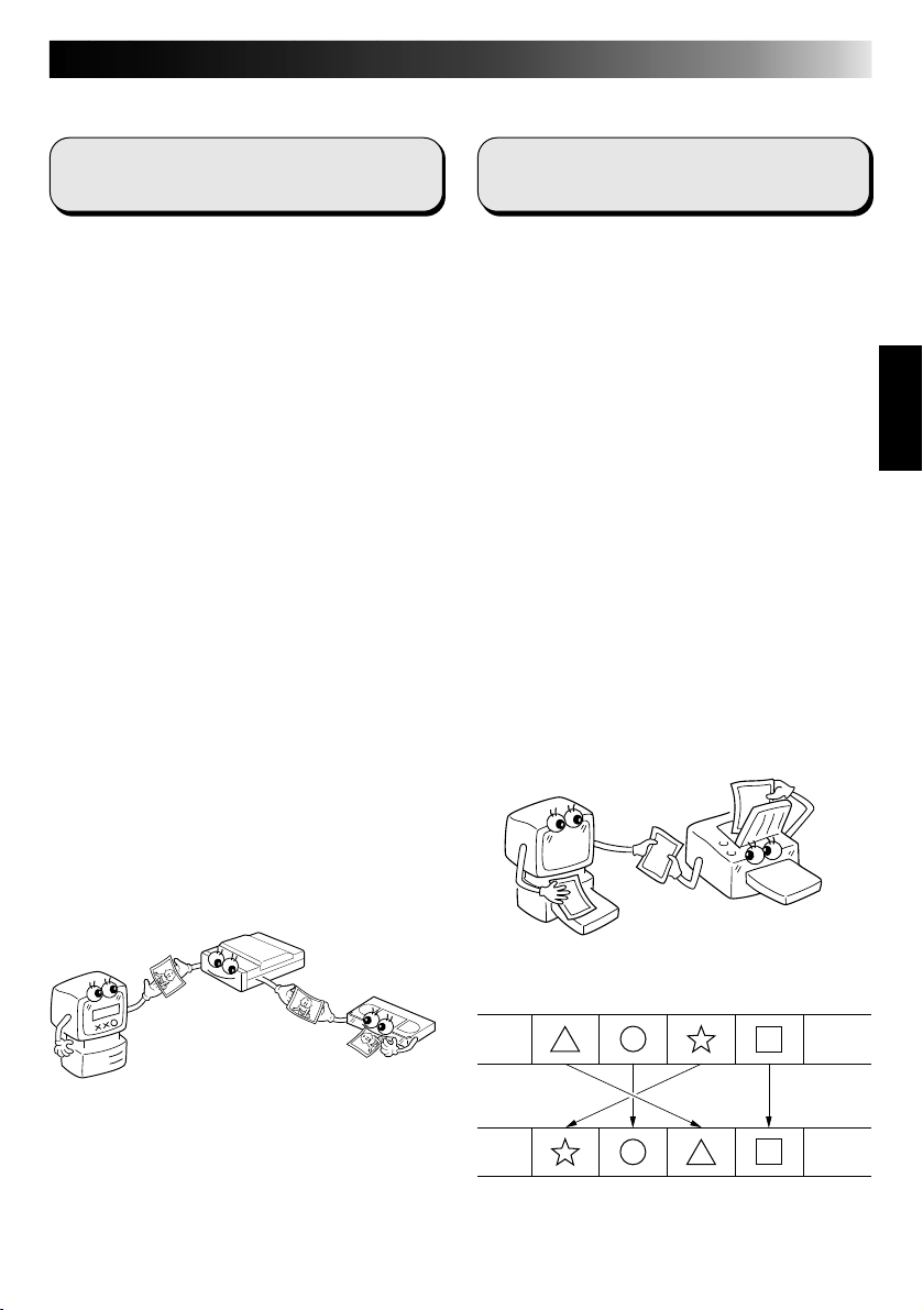
Assemble Editing
Selected scenes on a pre-recorded tape can
be edited in a specified sequence.
Pre-recorded tape
(on camcorder)
Recording tape
(on VCR)
Page 8

8
CONTENTS
MAJOR FEATURES 7
ADVANCED APPLICATIONS 10
CONTROLS AND CONNECTORS 11
CONNECTIONS (When Using JLIP Video Capture Software) 12
INTRODUCTION 14
INSTALLATION (JLIP Video Capture Software) 15
HOW TO OPEN THE PROGRAM 16
Preparation ................................................................... 16
INITIALIZATION 17
Initializing JLIP .............................................................. 17
Select units.................................................................... 18
HOW TO CLOSE THE PROGRAM 19
HOW THE DESKTOP WORKS 20
Main desktop window....................................................... 20
Menu bar ...................................................................... 21
VIDEO CAPTURE 24
Capturing video images ..................................................... 24
Step by step capture......................................................... 25
Automatic capture............................................................ 26
Program capture ............................................................. 26
Interval capture .............................................................. 28
PICTURE FORMAT SETTING 29
Selecting a picture format................................................... 29
ADDITIONAL OPERATIONS 30
Counter value change........................................................ 30
Counter reset ................................................................. 30
Delete index image and full image......................................... 31
Change ID ..................................................................... 31
SAVE PICTURE 32
Create new folder............................................................ 32
Saving ......................................................................... 32
Open index.................................................................... 33
Save the full image data .................................................... 33
Page 9

JLIP PLAYER SOFTWARE 34
Using JLIP player software data........................................... 34
How to store JLIP player software data ................................. 35
TROUBLESHOOTING 36
LIST OF ERROR MESSAGES 38
JLIP PLAYER SOFTWARE SECTION 41
CONNECTIONS (When Using JLIP Player Software) 42
When connecting to a video source unit with JLIP connector or to a
video printer................................................................
GETTING STARTED 44
INSTALLING (JLIP Player Software) 45
STARTING JLIP PLAYER SOFTWARE 46
MOVIE PLAYER WINDOW BUTTONS AND DISPLAYS 48
BASIC OPERATIONS 50
VIDEO PRINTER WINDOW BUTTONS AND DISPLAYS 56
VIDEO PRINTER OPERATION (GV-PT1) 58
Printing ........................................................................ 58
Adjusting picture equalization .............................................. 59
42
9
VIDEO PRINTER OPERATION (GV-PT2) 60
Auto capture .................................................................. 60
ADVANCED OPERATIONS 62
Changing ID number ......................................................... 62
Connecting other device during operation................................. 62
Changing the name of the device........................................... 63
Changing the device to use while connecting over
two same type devices ...................................................
Adjusting the gap between the stored edit-start point in the
computer and the dubbed one in the recording deck ..................
TROUBLESHOOTING 65
MAJOR SPECIFICATIONS 66
INDEX 67
63
64
Page 10
10
Create title indexes for your video
collection
Title index images can be captured from your
favorite recordings in intervals of 30 minutes,
1 hour, 1.5 hours, etc. using the Interval
Capture mode. Print the captured index
images on your PC printer using the computer's Print Screen facility, then attach them to
your cassettes.
Business presentations
Images captured from video can be incorporated into business documents to spice up
your presentations.
Internet homepage
Images captured from video can be incorporated in your Internet homepage using image
editing software.
ADVANCED APPLICATIONS
Video journal and postcards
Create your own original postcards, party
invitation cards and the like or keep a video
journal.
Page 11
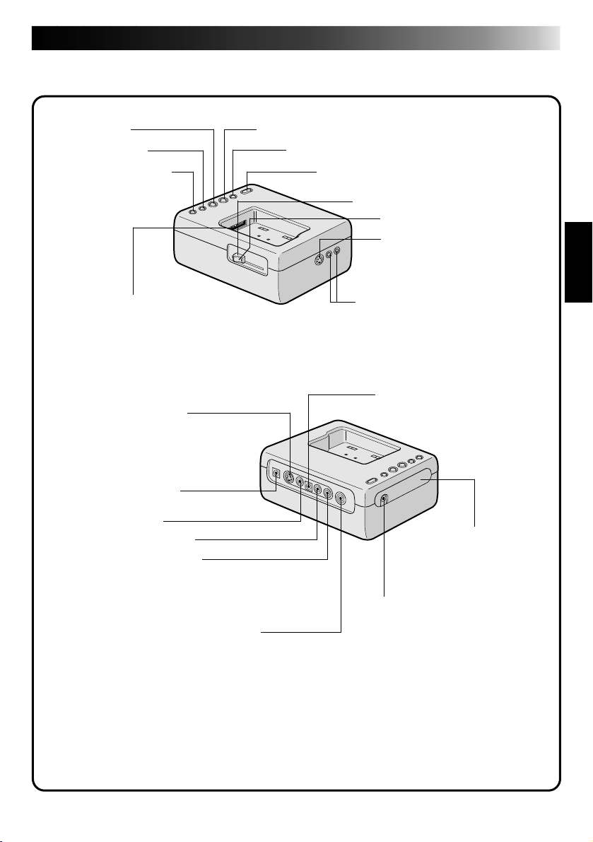
CONTROLS AND CONNECTORS
The controls and connectors marked * can be used only when the GR-DVM1 Digital
Camcorder is attached. For details of its operation, read the camcorder instruction manual.
* Stop button * Play button
* Rewind button * Pause button
* Fast forward button * Edit start button
* Lock lever
* Unlock button
* Digital jack Z p. 13
•Connect to the computer’s
RS-232C terminal (COM
port).
* MULTI connector
•The Docking Station can be connected with
the GR-DVM1 through this connector.
Never touch it with your hand or hit it with
a hard object; if the pins are damaged, the
connectors will become unusable due to
contact failure.
* S2 (Video) output jack
•Outputs the S-VIDEO signal.
(Also compatible with S1 and S2
connectors.)
JLIP jack
(JLIP: Joint Level Interface Protocol)
•Connect to a JLIP-compatible
Z p. 13
comcorder or VCR to control it from
the computer.
* DC output jack
•For dealer use.
11
DC input jack Z p. 13
* Video output jack
* Audio output jack (Left)
* Audio output jack (Right)
* Edit jack
Capture input (EXT.)/printer connector
* Remote control sensor
•Receives the remote
control signals for the
attached Camcorder.
Z p. 13
•Connect with the video output (stored image output) of the optional video printer. Even
when a TV is not connected to the video printer, this connection allows you to see the
images output from the video printer on the LCD screen while printing.
•The date and timecode are not shown on the LCD screen. If you want to print out the date
together with the images, connect a TV to the video output connector of the video printer
and operate it by referring to the TV screen.
•It is also possible to capture images from video equipment other than the GR-DVM1by
connecting the equipment to this connector. To make this operation possible, also attach
the GR-DVM1 and set its power switch to record mode without loading a tape.
Page 12
12
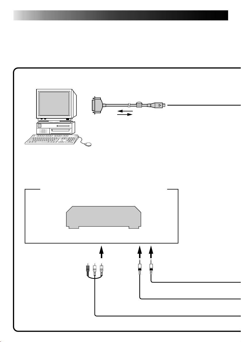
n To assure safety, make sure all units are turned off before making any connections.
n The video images will be displayed on the LCD screen of the attached GR-DVM1. You
cannot view the images on the computer screen.
n When connecting the provided cables, be sure to connect the terminals equipped with Core
filters to the Video Capture Docking Station.
n When using the Video Capture Docking Station, use the AA-V80U AC Adapter/Charger
(optional or provided with the camcorder).
Core filter
PC connection cable
To COM
(RS-232C) port
Personal computer
(provided)
CONNECTIONS
To Digital (8-pin)
connector
Image sources with JLIP and video output connectors
VCR (Recording deck)
(red) (white) (yellow)
To JLIP jack
To VIDEO output jack
Page 13
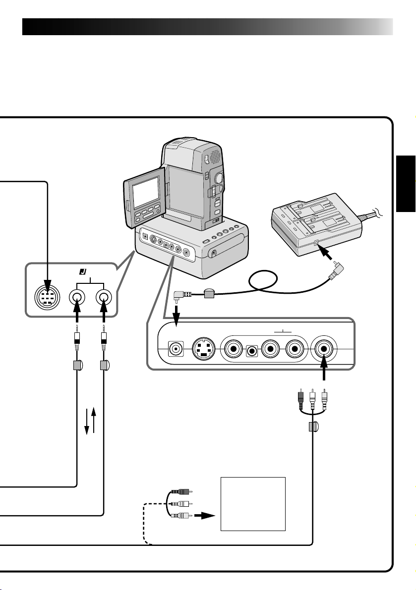
Video Capture
Docking Station
JLIP
Digital
Camcorder
AC Adapter/Charger
13
To DC
output
jack
AUDIO/VIDEO cable
(provided)
To JLIP
jack
Core
filter
3.5 mm dia. 4-pole
cables (provided)
Core filter
Other units
with video
output jack
DC cable (provided)
(red) (white) (yellow)
Core filter
To CAPTURE
INPUT
(EXT.)/
PRINTER
connector
Page 14
14
INTRODUCTION
What is video capture software ?
Video capture software is a type of application program that allows you to capture video
images from camcorders and VCRs and store them in personal computers running under the
WindowsT operating system. These images can be transferred from the video source to the
computer via a standard RS-232C communication interface. By processing the captured
images with commercially available image editing software, you can create your own unique
and highly personal illustrations and graphics for incorporation into everything from postcards
to newsletters and Internet homepages.
What is JLIP ?
JLIP* stands for Joint Level Interface Protocol, a new communication protocol which allows AV
units equipped with a JLIP terminal to be controlled by a personal computer.
*
is a registered trademark of JVC.
Operating Environment
● Personal computer with MicrosoftT WindowsT 3.1 or WindowsT 95
● CPU Intel DX4™ or higher processor
● Minimum RAM requirement: more than 8 MB
● Available Hard Disk space of at least 8 MB
● Colour display capable of at least 640 x 480 pixels, 256 colours
Recommended 1024 x 768, 16.77 Mil colours
● 1 free serial transmission port, compatible with 9600 bps transmission rate, connectable to
RS-232C with 9 pin serial connector.
Recommended compatible with UART 16550A
● Mouse (WindowsT compatible)
● CD-ROM drive
Note : An optional 9 pin serial conversion adapter is required for computers using serial
communication port other than standard 9 pin.
* MicrosoftT and WindowsT are either registered trademarks or trademarks of Microsoft Corporation in the
United States and/or other countries.
* Other product and company names included in this instruction manual are trademarks and/or registered
trademarks of their respective holders.
Connectable Devices
When using JLIP with Video units equipped with a JLIP connector :
● JVC camcorders or VCRs equipped with a JLIP connector.
When not using JLIP:
● Video units with video output connectors
Page 15

INSTALLATION (JLIP Video Capture Software)
WINDOWST 95
Refer to the WindowsT 95 manual or your
computer’s manual for details on basic
WindowsT 95 operating procedures.
WINDOWST 3.1
Refer to the WindowsT 3.1 manual of or your
computer manual for details on basic
WindowsT 3.1 operating procedures.
15
Installation Procedure
*To start the setup program...
Launch WindowsT 95
1
•Close any other applications that are
running.
Insert the "JLIP Video Capture" CD-ROM
2
into the CD-ROM drive.
Choose "Run" from "Start" on the taskbar.
3
If the "JLIP Video Capture" CD-ROM is in
4
Drive D, type "D:\JCPTE\SETUP" in the
box to the right of "Open". If the disk is
in Drive E, type "E:\JCPTE\SETUP".
•Click "OK".
•Once the setup program is running,
simply follow the instructions displayed
on-screen.
•When setup is complete, the "JLIP
Video Capture" icon appears on the
screen.
•"JLIP Video Capture Setup was completed successfully." appears.
Click "OK" to complete installation.
5
Installation Procedure
*To start the setup program...
Launch WindowsT 3.1
1
•Close any other applications that are
running.
Insert the "JLIP Video Capture" CD-ROM
2
into the CD-ROM drive.
Choose "Run" from "File" in the "Program
3
Manager".
If the "JLIP Video Capture" CD-ROM is in
4
Drive D, type "D:\JCPTE\SETUP" in the
box to the right of "Open". If the disk is
in Drive E, type "E:\JCPTE\SETUP".
•Click "OK".
•Once the setup program is running,
simply follow the instructions displayed
on-screen.
•When setup is complete, the "JLIP
Video Capture" icon appears on the
screen.
•"JLIP Video Capture Setup was completed successfully." appears.
Click "OK" to complete installation.
5
Page 16

16
The Video Capture software can be started up in the same way as any other program running
under Windows. The procedure differs slightly depending on whether you’re using WindowsT
3.1 or WindowsT 95.
HOW TO OPEN THE PROGRAM
Preparation
• Turn on your computer.
• Press the POWER button to turn on the power.
• Turn on the video source units (such as camcorders and VCRs).
• If you want to capture a still picture from a recorded tape, load the tape into the video unit.
• If you want to capture an image from the data stored in the JLIP Player Software, be sure to
load the disk on which the image is stored.
Close any programs that are running. You cannot run other programs simultaneously with
the Video Capture software.
With WindowsT 3.1, open the group of application icons in the Program Manager and
double-click the application icon you want to launch.
With WindowsT 95, click the [START] button on the taskbar, and the Program menu
appears on the screen. Move the mouse pointer over the program entry you want to run
and click to start the program.
Now let’s start the program.
If you’re using WindowsT 3.1, open the JLIP Video Capture group in the "Program Manager" and
double-click the JLIP Video Capture icon.
If you’re using WindowsT 95, select JLIP Video Capture from the "Start menu" and click to start.
Page 17
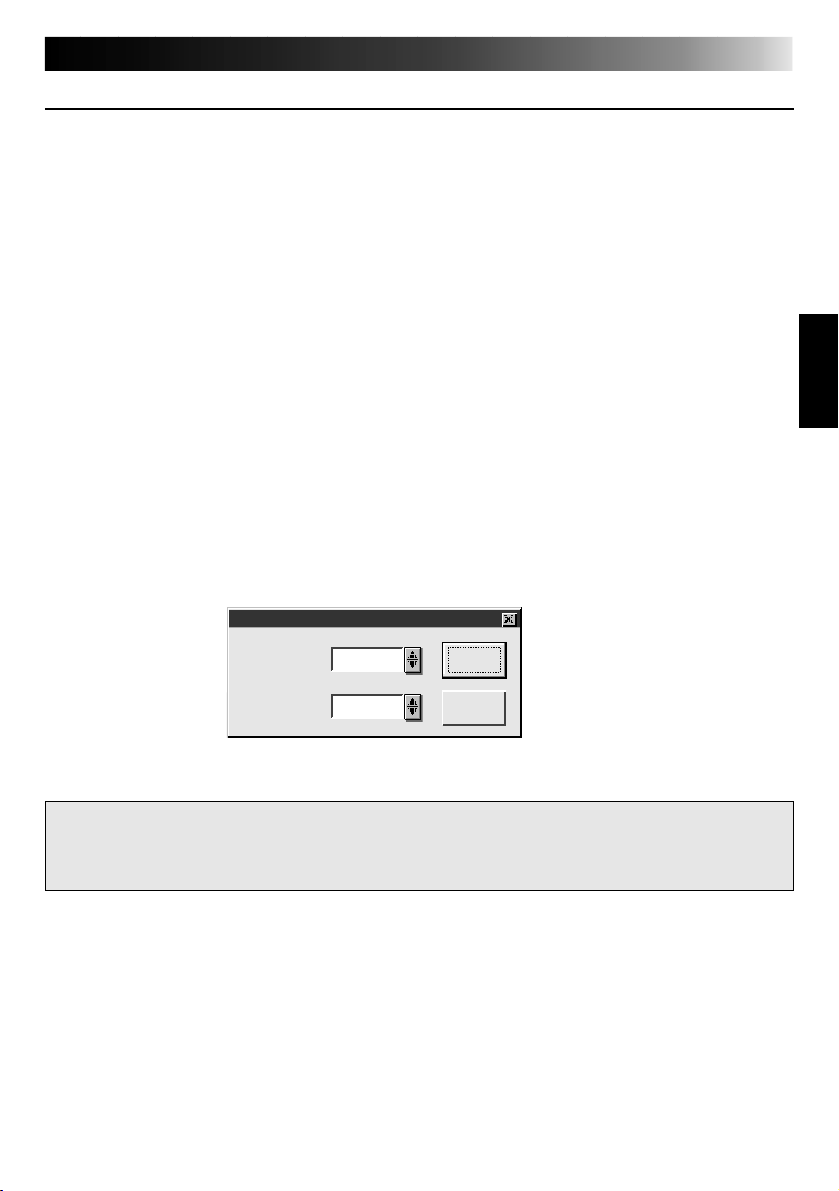
INITIALIZATION
17
INITIALIZING JLIP
The first time you start the Video Capture software, JLIP initialization is required. This sets which
of the computer’s COM ports (connector into which the RS-232C cable is plugged) is connected
to the GV-CB1 JLIP Video Capture Docking Station. The initialization window automatically
appears the first time you start the software after installation. Do not forget to carry out this JLIP
initialization procedure. The JLIP must be initialized again whenever you connect a new image
source or other unit to the JLIP Video Capture Docking Station.
1
.
Start the JLIP Video Capture software.
2
.
The "JLIP Initialization" screen automatically appears.
3
.
Select "COM Port".
•COM1 through COM4 ports are available. Check to see which COM port is connected to
the JLIP Video Capture Box and select it.
4
.
Select "Transfer Rate".
•Normally select 38400.
•38400 may not be available on some computers. When transmission errors take place
during use, switch to 19200 or 9600. Image data transmission will be slower at these
speeds.
5.
Click "OK". The "JLIP Initialization" window appears while the program checks for the
connected units.
JLIP Initialization
COM Port COM 1
38400Transfer Rate
NOTE : If you want to change a unit or COM port or Transfer Rate, select "Initialize" from
"Set-up" in the menu bar to call up the "JLIP Initialization" window. Repeat this
setting procedure.
If a connection is incorrect, a connected unit is not turned on, or the connection ID numbers
overlap, the message "Connection error" appears. Click "OK" to return to the Main desktop.
OK
Cancel
Page 18
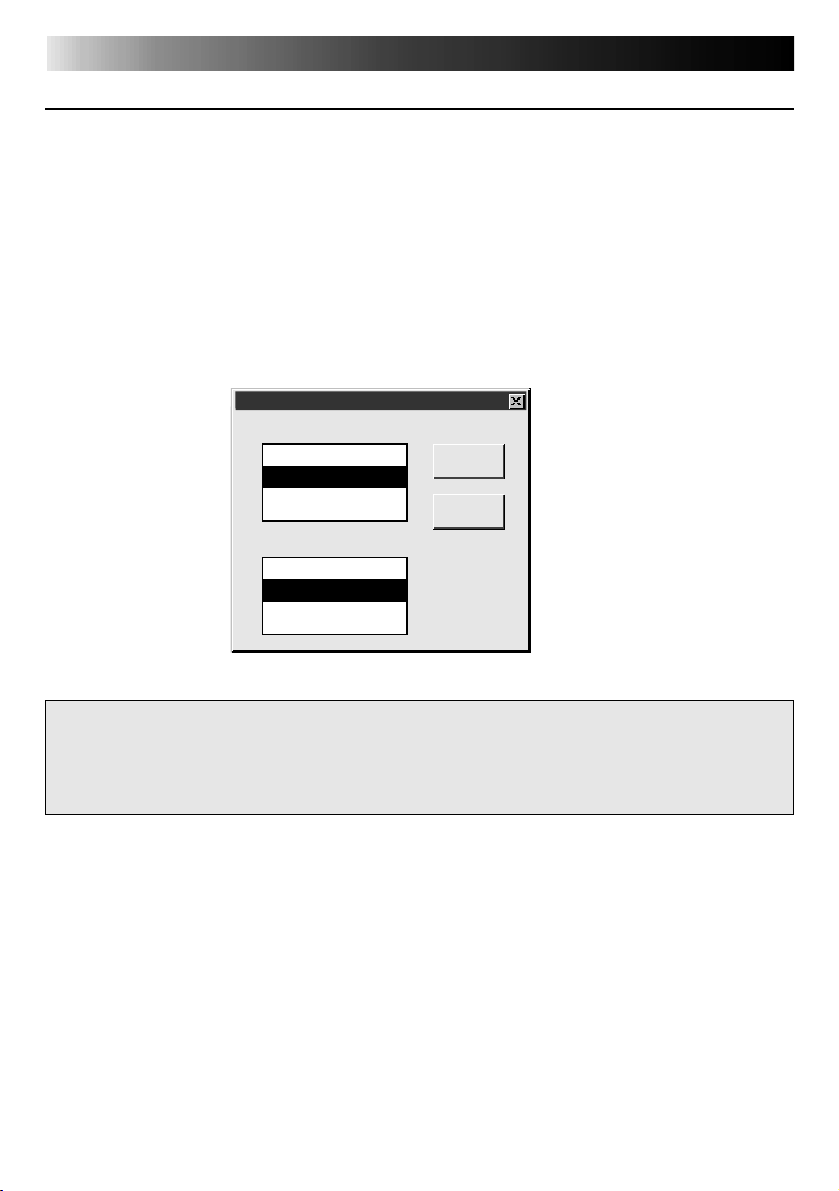
18
INITIALIZATION
SELECT UNITS
6
.
The "Device Selection" window appears, listing the JLIP devices.
7
.
Click the name of the desired unit.
•The word "VCRCAMERA" appears in the VCR box to indicate the Video source unit is now
in use.
•The word "MODULE" appears in the Video Capture box to indicate the Video Capture
Docking Station is now in use.
•Only one VCR and one Video Capture device can be selected.
8
.
Click "OK".
•The main desktop window returns (setting complete).
Device Selection
VCR
Not connected
06:VCRCAMERA
Video Capture
Not connected
83:MODULE
OK
Cancel
NOTE : The "Device Selection" window automatically appears when JLIP initialization is
complete. However, if you want to select equipment whose JLIP initialization has
already been carried out, select "Device Change" from "Set-up" in the menu bar to
call up the "Device Selection" window.
Page 19

HOW TO CLOSE THE PROGRAM
Double-click the control menu button in WindowsT 3.1 or click "Exit" in the "File" menu.
In WindowsT 95, simply click the Close button.
19
If you try to close the program with no image
saved, the message "The album has not been
saved. Save?" appears. Please note that if you
close without saving, all unsaved captured
data will be deleted.
Click "Exit" from "File" in the menu bar.
1
•The program closes.
File
New Album
Open Album
Save Album
Open JLIP (jlp) File
Save As JLIP (jlp) File
Save Image As…
Exit
Ctrl+S
Ctrl+A
Page 20
20
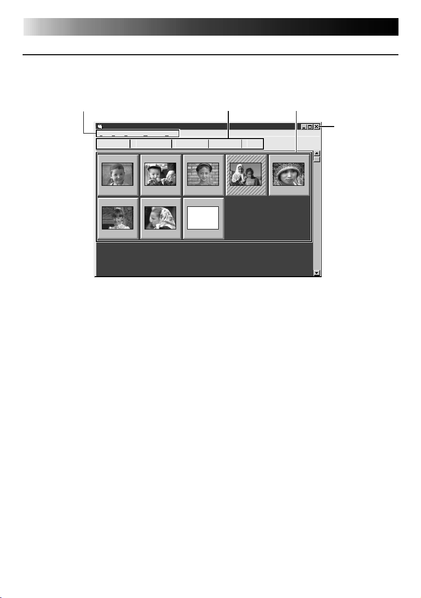
MAIN DESKTOP WINDOW
1.
Menu bar
JLIP Video Capture [–Untitled Folder–] (Untitled)
File Edit Set-up Window Help
TRANSFERCAPTURE
01
HOW THE DESKTOP WORKS
2.
MEMORY
INPUT
Control
buttons
JLIP
04
3.
Image display area
05
Close
button
00:01:23:120200:02:17:210300:07:01:19
06
00:39:03:110700:47:53:03
08
--:--:--:--
00:37:05:06
00:20:39:18
Menu bar
1
Displays function menus. See the next page for detailed information.
Control buttons
2
•CAPTURE button (Z page 25)
Press to CAPTURE a desired image from an image source. When pressed, an index
image appears under this button.
•TRANSFER button (
The TRANSFER button is used to start Automatic Transfer. Automatic Transfer is divided
into Program Capture and Interval Capture.
•MEMORY/INPUT button
Press to switch between the image stored in this unit and the image from the video
source.
•JLIP button (
The JLIP Video Capture software and JLIP Player software cannot run simultaneously.
When you want to run the JLIP Player software, press this button to disable the JLIP
Video Capture software. You may then start the JLIP Player software. To resume using the
JLIP Video Capture software, first select "Close Serial" from "File" on the JLIP Player
Software's menu bar, then press the JLIP button.
Z pages 27, 28)
Z pages 41 through 65)
Page 21
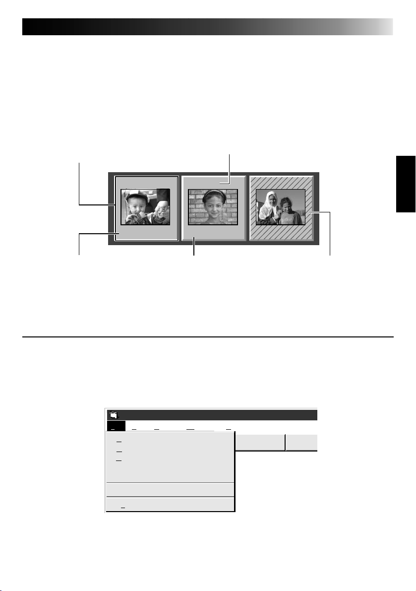
Image display area
3
Each time you press the Capture button an image is captured by this device. An index
image is transferred to the computer and displayed in the image area. Up to 99 images
can be captured, with up to five images per line. Index images are provided to allow you
to confirm that you have captured the images you want.
Index image: 80 x 60 pixels Full image: 640 x 480 pixels
Image display box
Click to select an image display box, and
•the border turns green
•Double-click an image display box, and Full
image data will appear if it has already been
transferred
Index numbers are
automatically assigned
02
00:02:17:210300:07:01:190400:37:05:06
21
Counter display
Indicates the current tape position
eg. 00 : 12 : 17 : 21
Hour : Min : Sec : Frame
Colours of counter numerals
Black : Full image transferred
White : Full image not transferred
(only index image
transferred)
Hatched like this when
the counter time has been
changed (Z p. 30)
MENU BAR
All program functions can be selected from the menus in the menu bar. Click any item in the
menu bar to open the corresponding pulldown menu. Then click the desired command in the
pulldown menu. Some menu entries are invalid depending on the program status. Invalid
commands appear lighter than valid commands.
JLIP Video Capture
File Edit Set-up Window Help
New Album
Open Album
Save Album
Open JLIP (jlp) File
Save As JLIP (jlp) File
Save Image As…
Exit
Ctrl+S
Ctrl+A
INPUTMEMORY
Page 22

22
HOW THE DESKTOP WORKS
Each pulldown menu is configured as follows
File
New Album
Open Album
Save Album
Open JLIP (jlp) File
Save As JLIP (jlp) File
Save Image As…
Exit
Edit
Transfer the Index Image
Transfer the Full Image
Modify…
Delete
Ctrl+S
Ctrl+A
Del
Erases the current album and creates a new album.
Opens an album (
Stores the open album (Z p. 32).
Opens a JLIP Player software file (Z p. 34) .
Converts to and saves as a JLIP Player software file (
Saves the image file to another folder or drive (Z p. 33).
Closes the program (Z p. 19).
•An index image of the image data in the Video Capture Docking
Station memory is transferred to your computer and displayed in
the selected image box (in the Step by Step capture mode).
•The video source unit scans the selected counter value and
transfers the index image to your computer (in the automatic
capture mode) (Z p. 30).
•A full image of the image data in the Video Capture Docking
Station memory is transferred to your computer (in the Step by
Step capture mode).
•The video source unit scans the selected counter value and
transfers the full image (680 x 480 pixels) to your computer
(Z p. 30).
Changes the scan timing in the automatic capture mode by changing the counter preset (Z p. 30).
Deletes the index image (Z p. 31).
(cont.)
Z p. 33).
Z p. 35).
Set-up
Capture Mode
Image Format
Device Change
Initialize
ID Change
Counter Reset
Two different modes available: Step by Step Capture and Automatic Capture
(
Z p. 25, 26, 28).
Selects image data format to be used in the transfer and capture mode
(Z p. 29).
To initialize a connected unit or to change a connected unit (Z p. 18).
Initialize when changing a COM port or transfer rate (
Changes the Video Capture unit’s ID number (Z p. 31).
Resets the VCR's counter (Z p. 30).
Z p. 17).
Page 23

Window
Arrange Index
VCR
[VCR] operation window
23
Arrange the index image after an index image has been deleted (Z p. 31).
The VCR operation window appears to allow the computer to control the
VCR.
VCR POWER button
VCR
I
FF/Forward Search
button
REW/Reverse Search
button
STOP
button
Counter display
00:01:23:12F
PLAY
button
PAUSE
button
Capture
Transfer
Forward Slow
button
Reverse Slow button
Capture button
Transfer button
VCR models operable on the VCR Operation Window (compatible with JLIP)
Help
Contents
About JLIP Video Capture
Display Help menu
F1
Display version information of this software.
NOTE : Counter reset
If you use a DV-format digital camcorder, counter information is represented by the
time code written on the tape. Counter reset is not possible.
Page 24

24
VIDEO CAPTURE
CAPTURING VIDEO IMAGES
There are three capture modes available: Step by Step, Program and Interval. The latter two
modes are available only when connected to a JLIP compatible video source unit. Step by Step
Capture mode must be used to capture images from a video source unit with no JLIP connector.
Image data flow
Video source
unit
When storing images on a 2HD disk,
• One image saved in the bitmap data format can be stored on one disk.
• About 28 images saved in the JPEG format can be stored on one disk.
This is the case when using floppy disks formatted for 1.44 MB.
Video signal
(Image stored in video memory)
Full image
(with a resolution of 640 x 480
pixels)
2 types of full size images
•Bitmap format Approx. 900 kB
•JPEG format Approx. 50 kB
(images are stored on a hard disk or the like)
NOTE:
•The index image is displayed in the
image display box.
•Each time the image display box is
double-clicked, the full image (640 x
480 pixels) is displayed only after vieo
data transfer is finished.
GV-DS1
PC
Index image
(with a resolution of
80 x 60 pixels)
Page 25

STEP BY STEP CAPTURE
Use the Step by Step Capture mode when you want to:
•Capture images from a video source unit with no JLIP connector
•Capture images from video units with video output connectors
•Capture a small number of images
•Confirm the images being captured.
Preparation
•Make sure all units are properly connected
(
Set-up
Capture Mode
Image Format
Device Change
Initialize
ID Change
Counter Reset
JLIP Video Capture
File Edit Set-up Window
TRANSFERCAPTURE
NOTE:
•Index images or Full images are transferred to the image display boxes bordered in green. Click and select the
desired box(es).
•When transferring full image data using
the Bitmap image format (
transfer takes a very long time, causing
the video source unit to stop playback
automatically.
Step by Step
Automatic
.bmp), the
9
Z p. 12).
•Click "Image Format" in "Set-up" and select
the desired format (
At the menu bar, click "Set-up" —
1
"Capture Mode" — "Step by Step".
•The Step by Step Mode is entered.
Click "CAPTURE" on the image you want
2
to capture.
•When a JLIP-compatible video source
unit is connected, you may use the
VCR Operation window. From the
menu, click "Window" and select
"VCR" to display the VCR Operation
window (
•When you press the CAPTURE button,
the full image (640 x 480 pixels) is
captured into the Video Capture
module's memory. The index image
(80 x 60 pixels) is simultaneously
transferred to the computer.
Index image data is transferred to the
3
computer.
•The message "No.1 index image being
transferred" appears during data
transfer.
The message "Transfer the full image ?"
4
appears. Click "Yes" and the full image
(640 x 480 pixels) is transferred to the
computer.
•You cannot use the TRANSFER button
in Step by Step Transfer mode.
The full image data is transferred to the
5
computer.
•The message "No.1 full image being
transferred" appears during image
transfer.
Repeat steps 2 through 5 as required.
6
25
Z p. 29).
Z p. 23).
Page 26

26
VIDEO CAPTURE
(cont.)
AUTOMATIC CAPTURE
Automatic video capture is available only when a JLIP-compatible video source unit is connected. There are two types of automatic capture: Program mode and Interval mode. You can
save time in either mode because, once the initial settings have been stored or you have decided
what pictures to capture, the subsequent capture process is carried out automatically.
PROGRAM CAPTURE
In the Program Capture mode, select the images you want to capture, and the JLIP Video
Capture Docking Station will automatically capture and transfer the images to your computer.
Preparation
•Make sure all units are properly connected
(
Z p. 12).
•Insert a tape into the video source unit.
Click "Image Format" from the "Set-up"
menu and select "Field Picture" in the
Set-up
Capture Mode
Image Format
Device Change
Initialize
ID Change
Counter Reset
Step by Step
Automatic
Capture Mode (
From the menu bar, click "Set-up" —
1
"Capture Mode" — "Automatic".
•The "Automatic Transfer" window
appears.
Select image to be transferred.
2
•When you select "Index Image", only
the index image (80 x 60 pixels) is
transferred to your computer.
•When you select "Index & Full Image",
both the index image (80 x 60 pixels)
and full image (640 x 480 pixels) are
transferred to the computer.
Z p. 29).
Select "Program Capture" and click
3
"OK".
NOTE:
•Before transferring your images, make
sure that enough space is available on
your hard disk. For full image data space
requirements,
•When transferring full image data using
the Bitmap image format (
transfer takes a very long time, causing
the video source unit to stop playback
automatically.
Z p. 24.
.bmp), the
9
Page 27

VCR
27
On the menu bar, click "Window" —
4
"VCR" to call up the VCR Operation
window.
I
00:01:23:12F
Capture
Transfer
Operate the video source unit via the
5
VCR Operation window and click the
"Capture" button to capture the desired
video image.
Click the "Capture" button on the desired
6
video image, and index image (80 x 60
pixels) is transferred to the computer.
•The message "No.1 index image being
transferred" appears during data
transmission.
Repeat steps 5 and 6 as necessary.
7
Click "Transfer" button.
8
•If you want to capture the full image
(640 x 480 pixels) after capturing the
"Index Image" in step 2, click "Index &
Full Image" and then click the "Transfer" button.
1. The message "Index No.1 being
scanned" appears while the video
source unit is scanning the picture to
be captured.
2. The message "No.1 index image being
transferred" appears and then "No.1
full image being transferred." appears
while the full image data is being
transferred to the computer.
3. The images captured in step 7 are
scanned by the video source unit and
automatically transferred to the
computer.
Page 28

28
INTERVAL CAPTURE
The Interval Capture mode is best suited for
capturing images at set intervals from a video
source unit with a JLIP connector.
Set-up
Capture Mode
Image Format
Device Change
Initialize
ID Change
Counter Reset
VCR
I
NOTE:
•
Make sure that enough hard disk space is
available on your computer before
executing video transfer.
For full image data space requirements,
Z p. 24.
•Transfer of the index image and full
image starts at the image box bordered
in green.
Click and select the desired image box.
•When transferring full image data using
the Bitmap image format (
transfer takes a very long time, causing
the video source unit to stop playback
automatically.
Step by Step
Automatic
00:01:23:12F
Capture
Transfer
.bmp), the
9
VIDEO CAPTURE
(cont.)
Preparation
•Make sure all units are properly connected
Z p. 12).
(
•Insert a tape into the video source unit.
In the "Set-up" menu, click "Image Format".
Select "Field Picture" in the Capture Mode.
Z p. 29).
(
At the menu bar, click "Set-up" — "Capture
1
Mode" — "Automatic".
•The "Automatic Transfer" window
appears.
Select the data to be transferred.
2
•When you select "Index Image", only the
index image (80 x 60 pixels) is transferred
to your computer.
•When you select "Index & Full Image",
both index image (80 x 60 pixels) and full
image (640 x 480 pixels) are transferred
to the computer.
Select "Interval Capture".
3
Set the interval.
4
•Select the time interval at which images
are captured.
Set the number of images to be captured
5
and click "OK".
•From 1 up to 99
Click "Window" — "VCR" to call up the
6
VCR Operation Window. Start video
playback a few seconds prior to the point
where you want image capturing to start.
Operate the video source unit via the VCR
7
Operation window and click the "Transfer"
button at the desired image to start the
capture function.
1. The message "No. 1 index image being
transferred" appears while the index image
is being transferred to the computer.
2. When you select "Index & Full Image" in
step 2, the message "No. 1 full image being
transferred" appears while the full image is
being transferred to the computer.
3. The message "Index No. 2 being scanned"
appears while the video tape is fast-forwarded and played at the time intervals set
in step 4 to scan the video data on the VCR.
• The image selected when "Transfer" is
clicked is captured and subsequent images
are captured at the time interval specified
by the counter value selected in step 4.
• The video source unit enters the Pause
mode when capture is complete.
Page 29

PICTURE FORMAT SETTING
SELECTING A PICTURE FORMAT
Under "Image Format", you can specify the full image format and the capture mode.
At the menu bar,
1
click "Set-up" —
"
Image Format".
•The "Image
Format" window
appears.
Select format.
2
•There are two different settings available: "JPEG (
bmp)". Refer to "Picture Data Format"
below for details.
TRANSFER DATA
The full image can be captured and transferred in two different formats.
9
Picture Data Format
● JPEG (9. jpg)
•
This is the default setting. If you do not set Picture Format, image data is captured in this
format.
•
JPEG (Joint Photographic Expert Group) is a leading standard defining the compression and
decompression of still color pictures.
•
The size of transferred image is smaller because the images are compressed. This results in a
shorter transfer time.
● Bitmap (9. bmp)
•
Transfer time is longer when you use this format because there is no data compression. The
benefit is that picture quality is maintained with no deterioration.
•
Bitmap is a data format representing characters and graphics with combinations of pixels.
Full image resolution is 640 x 480 pixels with 16.77 million colors (24-bit color).
Index image resolution is 80 x 60 pixels with 16.77 million colors (24-bit color).
Set-up
Capture Mode
Image Format
Device Change
Initialize
ID Change
Counter Reset
. jpg)" and "Bitmap (9.
Select capture mode.
3
•There are two different settings avail-
able: "Frame Picture" and "Field
Picture". Refer to "Capture Mode"
below for details.
Click "OK".
4
•This completes picture format setting.
•This setting takes effect the next time
you use the capture function.
29
Capture Mode
● Frame Picture
•
This is the default setting. If you do not set Picture Format, images are captured in this
mode.
•
Since a frame consists of two overlapping 1/60 sec. images (one 1/30 sec. image forms a
field), it is unstable when capturing fast-moving motion pictures.
● Field Picture
•
While a field contains only half the data of a frame — meaning that vertical resolution is
half that of a frame — images captured from a fast-moving motion picture are more stable
than when captured with "Frame Picture".
Page 30

30
ADDITIONAL OPERATIONS
COUNTER VALUE CHANGE
If you want to replace a captured image with a different one, you can capture the new one by
changing the counter value.
02
00:02:17:21
Edit
Transfer the Index Image
Transfer the Full Image
Modify…
Delete
02
00:01:23:12
02
00:01:23:12
NOTE : Note that if the index image data
is saved in step 4, the hatching
pattern indicating the change will
no longer appear the next time it
is called up.
Del
Click the image display box of the index
1
number you want to change.
•The box is bordered in green.
Open the menu bar and click "Edit" —
2
"Modify…".
•The "Modify Capture Point" window
appears.
Enter a new counter value.
3
Click "OK".
4
•The index image is surrounded by a
hatching pattern indicating that a
change is being made.
•The counter value is changed to the
value you just entered.
Open the menu bar and click "Set-up" —
5
"Capture Mode" — "Automatic", then
select "Program Capture" in the "Automatic Transfer" window and click "OK".
Play the tape on the video source unit
6
and click "Edit" — "Transfer the Index
Image".
•Index image data at the counter setting
is captured.
•Be sure to complete steps 1 through 7.
If they are not all followed, the index
image and the full image will be
different as the full image data will not
have been changed in step 6.
Click "Edit" — "Transfer the Full Image".
7
•Full image data at the counter setting is
transferred.
COUNTER RESET
You can change the counter setting on connected video source units (VHS, VHS-C).
Set-up
Capture Mode
Image Format
Device Change
Initialize
ID Change
Counter Reset
Open the menu bar and click "Set-up" —
1
"Counter Reset".
•The VCR's counter is reset.
•The counters of DV-format digital
camcorders cannot be reset.
Page 31

31
DELETE INDEX IMAGE AND FULL IMAGE
You can delete any captured picture. Both index image (80 x 60 pixels) and full image (640 x
480 pixels) are deleted.
02
00:02:17:21
1
2
Edit
Transfer the Index Image
Transfer the Full Image
Modify…
Delete
Window
Arrange Index
VCR
Del
CHANGE ID
You can change the Video Capture Unit’s ID number.
3
Click the image display box you want to
delete.
•The box is bordered in green.
Open the menu bar and click "Edit" —
"Delete".
•This deletes the selected image data.
Then click "Window" — "Arrange
Index".
•This removes the deleted index image’s
space and renumbers the remaining
index display box. You can still run the
program without re-arranging the
index.
Set-up
Capture Mode
Image Format
Device Change
Initialize
ID Change
Counter Reset
Open the menu bar and click "Set-up" —
1
"ID Change".
•ID Change window appears.
Enter a new ID number.
2
Click "OK".
3
•This completes the ID number change.
Open the menu bar and click "Set-up" —
4
"Initialize".
•The "JLIP Initialization" window
appears.
•Start JLIP initialization (
Z p. 17, 18).
Page 32

32
SAVE PICTURE
CREATE NEW FOLDER
Creating a new folder (directory) is a good idea when capturing an image from another video
tape.
File
New Album
Open Album
Save Album
Open JLIP (jlp) File
Save As JLIP (jlp) File
Save Image As…
Exit
Ctrl+S
Ctrl+A
Open the menu bar and click "File" —
1
"New Album".
•The image display area is refreshed.
•If the index image data on screen is not
saved, you will be asked whether to
save or not.
SAVING
Select when storing the contents displayed in the image display area (page 21).
File
New Album
Open Album
Save Album
Open JLIP (jlp) File
Save As JLIP (jlp) File
Save Image As…
Exit
Ctrl+S
Ctrl+A
Open the menu bar and click "File" —
1
"Save Album" .
•The "Save Album" window appears.
Type the folder name and title.
2
•You can save without entering any title.
Click "OK".
3
•The file is saved.
Enter folder name
Save Album
Folder:
c:\capture\index001
(Untitled)
Title:
c:\
capture
c:
Select directory Select drive
Enter title name
OK
Cancel
Page 33

OPEN INDEX
33
File
New Album
Open Album
Save Album
Open JLIP (jlp) File
Save As JLIP (jlp) File
Save Image As…
Exit
Ctrl+S
Ctrl+A
Open the menu bar and click "File" —
1
"Open Album".
•The "Open Album" window appears.
Select the name of the folder (directory).
2
Click "OK".
3
SAVE THE FULL IMAGE DATA
You can save a file under another name or in another folder so that you can edit it without
losing the original.
By processing the captured images with commercially available image editing software, you
can create your own unique and highly personal illustrations and graphics for incorporation
into everything from postcards to newsletters and Internet homepages.
Click the image display box of the Index
1
File
New Album
Open Album
Save Album
Open JLIP (jlp) File
Save As JLIP (jlp) File
Save Image As…
Exit
Ctrl+S
Ctrl+A
No. to be saved.
•The image display box is framed in
green.
Click "File" — "Save Image As…" on the
2
menu bar.
•The "Save Image As… (Index No.
window appears.
Click the name of the desired folder
3
(directory) in the Select Directory box
and enter the file name.
•When saving the data to floppy disk,
enter the drive name as well.
)"
Click "OK".
4
NOTE:
•It is not possible to change the image
format when saving the full image data
(
Z p. 29).
•If the full image data has not been
transferred to the computer, it is not
possible to save it. First transfer the full
image data, then save it.
Page 34

34
JLIP PLAYER SOFTWARE
USING JLIP PLAYER SOFTWARE DATA
The GV-DS1 Video Capture Docking Station can capture JLIP Player software data at an edit-in
point corresponding to a preset counter number.
Preparation
•Make sure all units are properly connected
(
Z p. 12).
•Insert the tape program edited with the
Player Software into the video source unit.
•If the data is stored on a floppy disk, load
disk into the floppy disk drive.
File
New Album
Open Album
Save Album
Open JLIP (jlp) File
Save As JLIP (jlp) File
Save Image As…
Exit
Ctrl+S
Ctrl+A
Open the menu bar and click "File" —
1
"Open JLIP (jlp) File".
•The "Open JLIP(jlp) File" window is
displayed.
Double-click the name of the desired
2
folder (directory) in the Select Directory
box.
•If the data is stored on a floppy disk,
enter the drive name.
Click on the file name to select it.
3
Click "OK".
4
•The computer monitor displays Scene
No., counter number at Edit-in Point,
and a blank image box.
Open the menu bar and click "Set-up" —
5
"Capture Mode" — "Automatic".
Select the data you want to transfer and
6
"Program Capture" and click "OK".
Click the "TRANSFER" button.
7
•The image data scanned by the video
source unit is automatically transferred
to your computer.
Page 35

HOW TO STORE JLIP PLAYER DATA
Data from this unit can be converted to JLIP Player software files.
If index image data is saved as a JLIP Player software file, the file can be printed with the
optional GV-PT1/GV-PT2 Video Printer.
Refer to the instruction manual for details.
Preparation
•Make sure all units are properly connected
(
Z p. 12).
•Insert a video tape into the video source
unit.
•If you want to store the data on a floppy
disk, load a data disk into the floppy disk
drive, create a directory and sub-directory
File
New Album
Open Album
Save Album
Open JLIP (jlp) File
Save As JLIP (jlp) File
Save Image As…
Exit
Ctrl+S
Ctrl+A
on the data disk (
Open the menu bar and click "File" —
1
"Save As JLIP (jlp) File".
•The "Save As JLIP (jlp) File" window is
displayed.
Enter the folder name (directory) and file
2
name.
•If you want to store the data on a
floppy disk, enter the drive name.
Click "OK".
3
•The data converted to a JLIP Player
software file is stored on the floppy disk
in the selected drive.
•JLIP Player software files can be used
for video program editing or printed
with the video printer.
Z p. 54).
(Z p. 58, 60)
35
NOTE : When stored data is opened with
the JLIP Player software, the edit-in
and edit-out points have the same
counter value. When you want to
perform program editing, change
the counter number at the edit-out
point in the JLIP Player software’s
"Modify Edit Points".
Page 36

36
NOTE : External noise or disturbance may interfere with the microprocessors built into the
GV-DS1 JLIP Video Capture Docking Station. If this happens, turn the power off and
then turn it on again.
TROUBLESHOOTING
Problem
No effect when clicking the
Input Select/Memory
buttons.
The video equipment image
is not displayed on the
connected TV.
The video unit does not
operate when "Window" —
"VCR" in the menu bar and
"VCR" in the "VCR" operation window are clicked.
Reverse Slow Play and
Forward Slow Play not
available in "VCR" operation
window.
The"VCR" operation
window display shows a
different operation from
what the video unit is
actually doing.
On-screen display of video
unit is stored in memory.
Counter display appears in
the image display box even
when there is no tape in the
video unit.
Cause
v The windows do not change during transfer
or compression of index image/full image data.
v The video is displayed on the LCD screen of
the attached GR-DVM1. It is not possible to
check the images on the computer.
v When video equipment is connected to the
CAPTURE EXT IN/PRINTER connector, its
video is displayed on the LCD screen of the
GR-DVM1.
v The counter display in the "VCR" operation
window turns blue.
v Is your video unit compatible with JLIP ?
Only JLIP-compatible units can be
operated.
If you are using a JLIP-compatible unit and
it still won’t work, check to make sure that
it is correctly connected.
v Is the video unit selected in "Select Unit" ?
Select correctly.
v Initialize JLIP.
v Make sure the video unit is turned on.
v These are available only when the video
unit has a Slow Play function.
v Slow Play in the VCR operation window
automatically switches to Play after
approximately 20 seconds.
v In some cases, the video unit may continue
slow-motion playback even when the
"VCR" operation window changes from
Slow Play to Play. Check your video unit’s
instruction manual for details.
v If your video unit has an onscreen display,
turn it off.
v When capture video data from a powered-
on video unit with no tape loaded, a
counter display may appear in the image
display box. Images corresponding to the
displayed counter number can no longer be
caputred.
Page
—
—
23
11 – 13
19
18
—
23
—
—
Page 37

TROUBLESHOOTING
(cont.)
37
Problem
Cannot capture video data
with the desired counter
number.
Counter cannot be reset.
Program capture suddenly
stops.
After finishing video
capture, the video file
remains in the JCPT folder
(where the program run file
is contained).
JLIP initialization not
possible.
With Video capture/
Transfer done in Automatic
Transfer mode, the captured
image looks like two
pictures laid one upon
another.
Cause
v There may be a slight difference between
the counter of the video image that you
want to capture and the Index image data/
Full image data captured in the computer.
This is not a malfunction.
v Counter reset is not available with digital
camcorders.
v When you start program capture at the
beginning of the tape, the video unit stops
playback, ending program capture.
Start video capture about 20 seconds after
the point where the recording begins.
v If you want to erase the file because of
limited hard disk space, start the program
once then close it. The video remaining in
the JCPT folder will be cleared.
v Make sure that the IRQ (Interrupt ReQuest)
is not being used by another device.
v COM port selection is wrong. Confirm the
COM port number and execute JLIP
initialization again.
v In this case, video capture is not possible
using the "Frame Picture" setting. Change
the setting to "Field Picture" and try video
capture again.
Page
25 – 28
30
26
—
18
29
The monitor displays of the application software illustrated in this manual may differ from
those you are actually viewing depending on the operating environment of your computer.
Operation will be significantly slower when used in an environment other than that recommended (page 14).
While basic VCR operations such as playback and fast-forward are available, a "transmission error" may occur in some models during video transfer. In this case, start the software
again, and turn the power of the Video Capture Docking Station off and on.
Page 38

38
LIST OF ERROR MESSAGES
Message
COM port is not
available.
Connected device
not found.
Battery depleted.
Stop transfer ? (Yes/
No)
Error — Transfer
halted.
v Appears when:
m Action:
v Not connected to COM port set by JLIP Initialize.
m Check the COM port number and connector and
retry JLIP initialization.
v Connected devices are not turned on.
v Selected COM port is not connected properly.
m Make sure connection is proper and carry out JLIP
initialization. Then turn on this unit and the
connected devices.
v JLIP Video Capture Docking Station battery level is
low.
m Yes... Transfer stops. Quit the program and turn off
all units. Replace batteries with new ones.
No... Select when transfer is about to end. Replace
batteries when transfer is complete. Since
data may not have been transferred correctly,
check the data after replacing the batteries.
v Video unit is brought to STOP or ends playback
during automatic capture.
m Check the auto capture setting.
v Full image data (640 x 480 pixels) cannot be
captured if you start auto capture at the beginning
of the tape. Video capture stops if video playback
is stopped.
m Start video capture 20 seconds after the start of the
recording.
v Tape is too short to match the preset number of
images or there is a section of non-recorded tape.
m Click "OK", check the tape length and re-enter the
number of images to be captured. Use a fully
recorded tape.
Page
18
18,19
11
—
28
Page 39

39
Message
Execute after
playing back the
VCR.
Not enough disk
space is available.
Communication
error.
Check the capture
device.
v Appears when:
m Action:
v Video unit is not in Play mode during Interval
Capture.
m Click "OK", set the video unit to Play and click
"Transfer" again.
v Remaining disk space is under 1 MB.
m Click "OK" , check disk space and select a drive
with space available with Store As.
v If operation stops after this message appears, turn
the Capture Docking Station off and then on again.
Images stored in memory will be lost.
m Do not use any other application while JLIP Video
Capture and JLIP player are running as it may
interfere with communication. Do not click and
move the mouse during data transfer.
v If your computer's energy saver, battery voltage
indication or screen saver is engaged, the image
data transmission may be interrupted.
m Disengage these functions. Refer to your
computer's instructions manual on details.
v If operation stops after this message appears, turn
the Capture Docking Station off and then on again.
Images stored in memory will be lost.
Page
28
—
—
—
Page 40

40
MEMO
Page 41

41
JLIP PLAYER SOFTWARE
SECTION
q The Readme.TXT file provides additional information for setup and information
that is not included in the instruction manual. Please read the file before installing
the provided software program.
q You can find the latest information (in English) on the provided software program
at our world wide web server at http://www.jvc-victor.co.jp/
Page 42

42
TW
CONNECTIONS (When Using JLIP Player Software)
WHEN CONNECTING TO A VIDEO SOURCE UNIT WITH JLIP
CONNECTOR OR TO A VIDEO PRINTER
n Be sure to turn off the power of all connected units before making any connections.
n When connecting the provided cable, be sure to connect the plug with the Core Filter to the
Video Capture Docking Station.
To COM port
(RS-232C)
PC
When connected with the Video Printer
To JLIP connector
Video Printer equipped
with a JLIP connector
PC connection
cable (provided)
3.5 mm diameter
4-pole cable
(provided)
Connect this if
the video unit has
an S-Video output
connector
To S-Video input connector
To video input connector
Core
Filter
To digital
connector
(8 pin)
S-Video
cable
If you edit using a non-JVC VCR...
It is possible to use the remote control unit provided with the GR-DVM1.
Also refer to the GR-DVM1’s instructions on connection and operation
with your brand of VCR.
NOTE:
Some VCR brands or models cannot be operated.
RM-V708U
Page 43

n When using the Video Capture Docking Station, use the AA-V80U AC Adapter/Charger
(optional or provided with the camcorder).
Digital camcorder
JLIP
JLIP Video Capture
Docking station
43
To JLIP
jack
Core Filter
Connect this
if the video
unit has a
JLIP
connector
Video cable
Connect to TV
AC Power
Adapter/Charger
To DC
output jack
3.5 mm
diameter 4pole cable
(provided)
To S-Video output jack
To video output jack
Connect
to TV
TV
DC
cord
Core
Filter
Connect this
if the video
unit has an
S input jack
To S
output
jack
Core
Filter
S-Video
cable
(provided)
AUDIO
To S-
VIDEO
input
jack
input
jacks
(L/R)
JVC Video unit
(Recording deck)
(yellow) (white) (red)
Core
Filter
AUDIO/
VIDEO
cable
(provided)
To
(red) (white) (yellow)
To edit jack
To video/
audio output
jack
To
VIDEO
input
jack
To remote
pause jack
EDIT cable
(provided)
Page 44

44
GETTING STARTED
What is JLIP ?
JLIP* stands for Joint Level Interface Protocol, a new communication protocol which allows AV
units equipped with a JLIP terminal to be controlled by a personal computer.
*
is a registered trademark of JVC.
Operating Environment
● Personal computer with MicrosoftT WindowsT 3.1 or WindowsT 95
● CPU Intel DX4™ or higher processor
● Minimum RAM requirement: more than 8 MB
● Available Hard Disk space of at least 8 MB
● Colour display capable of at least 640 x 480 pixels, 256 colours
Recommended 1024 x 768, 16.77 Mil colours
● 1 free serial transmission port, compatible with 9600 bps transmission rate, connectable to
RS-232C with 9 pin serial connector.
Recommended compatible with UART 16550A
● Mouse (WindowsT compatible)
● CD-ROM drive
Note : An optional 9 pin serial conversion adapter is required for computers using serial
communication port other than standard 9 pin.
* MicrosoftT and WindowsT are either registered trademarks or trademarks of Microsoft Corporation in the
United States and/or other countries.
* Other product and company names included in this instruction manual are trademarks and/or registered
trademarks of their respective holders.
Devices to connect to the VIDEO CAPTURE BOX
● Camcorder equipped with JLIP connector
● Video printer equipped with JLIP connector
Page 45

INSTALLING (JLIP Player Software)
WINDOWST 95
Refer to the WindowsT 95 manual or your
computer’s manual for details on basic
WindowsT 95 operating procedures.
WINDOWST 3.1
Refer to the WindowsT 3.1 manual of or your
computer manual for details on basic
WindowsT 3.1 operating procedures.
45
Installation Procedure
*To start the setup program...
Launch WindowsT 95
1
•Close any other applications that are
running.
Insert the "VIDEO MOVIE PLAYER" CD-
2
ROM into the CD-ROM drive.
Choose "Run" from the "Start" on the
3
taskbar.
If the "VIDEO MOVIE PLAYER" CD-ROM
4
is in Drive D, type "D:\VMPE\SETUP" in
the box to the right of "Open". If the disk
is in Drive E, type "E:\VMPE\SETUP".
•Click "OK".
•Once the setup program is running,
simply follow the instructions displayed
on-screen.
•When setup is complete, the "MOVIE
PLAYER" icon appears on the screen.
•"MOVIE PLAYER Setup was completed
successfully." appears.
Click "OK" to complete installation.
5
Installation Procedure
*To start the setup program...
Launch WindowsT 3.1
1
•Close any other applications that are
running.
Insert the "VIDEO MOVIE PLAYER" CD-
2
ROM into the CD-ROM drive.
Choose "Run" from "File" in the "Program
3
Manager".
If the "VIDEO MOVIE PLAYER" CD-ROM
4
is in Drive D, type "D:\VMPE\SETUP" in
the box to the right of "Open". If the disk
is in Drive E, type "E:\VMPE\SETUP".
•Click "OK".
•Once the setup program is running,
simply follow the instructions displayed
on-screen.
•When setup is complete, the "MOVIE
PLAYER" icon appears on the screen.
•"MOVIE PLAYER Setup was completed
successfully." appears.
Click "OK" to complete installation.
5
Page 46

46
Serial Port Selection
Select a Serial Port.
MOVIE
PLAYER
COM 1
COM 2
COM 3
COM 4
STARTING JLIP PLAYER SOFTWARE
Starting JLIP Player Software
PREPARE DEVICE(S)
1
Turn the device(s) on and set the
camcorder's Power Dial to "PLAY".
ACCESS MOVIE PLAYER
2
Double-click the MOVIE PLAYER icon
and the Serial Port Selection dialog box
appears.
SELECT SERIAL PORT
3
Select the port number of the connector
you are using to connect the computer to
the Video Capture Docking Station.
•If the connector number is A, B... A
corresponds to 1.
•Click "OK".
•If the connection is correct, the Device
Selection dialog box appears.
OK
Initializing JLIP
Now checking devices' ID ...
CANCEL
ID:10
Page 47

Device Selection
Select device to control.
VCR
DISCONNECT
06:VCRCAMERA
VIDEO PRINTER
DISCONNECT
OK
CANCEL
•An error message "No devices detected
to connect. Power ON all devices in
system." appears . . .
...when a wrong port number is
selected.
...when the connection is wrong.
...when the device's ID number is
already in use.
...when the device's power is not
turned on.
Check the Serial Port selection, too.
To return to step 1, check the connection
and the device's power and try again.
•When all serial COM ports are
occupied by other applications the
error message "Error--This application
will close. Check devices--Confirm that
power is ON." appears. Free a serial
COM port to start up JLIP Player
Software.
SELECT DEVICE(S)
4
Click on the name of the device you
wish to control. Clicking "OK" brings up
the MOVIE PLAYER window.
•It is possible to select a second device
of a different type simultaneously, but it
is impossible to select two devices of
the same type simultaneously.
47
Page 48

48
MOVIE PLAYER WINDOW BUTTONS AND DISPLAYS
5.POWER button
Control-menu box
Menu bar
1.COUNTER system
MOVIE PLAYER
File Video Printer HelpEdit
COUNTER
POWER
Non Drop
OFFON
2.Tape counter
display
00:00:00:00F
MEMO
3.ID number
06
ID
Title bar
Minimize button
4.FILE name
FILE
6.MEMO
PROGRAM PLAYBACK
SCENE
ELAPSED TIME
CUT IN CUT OUT
10. Camcorder's operation
STARTSCENE
00:00:00:00F
MODE
STILL
PLAY
SEARCH
SLOW
FF
REW
IN/OUT
13. IN/OUT point button
11. MODE display
8.START button
12. SCENE button
buttons
14. Message display
9.ELAPSED TIME7.IN/OUT point display
Drop Frame System**
This system automatically adjusts the gap between the time code* (1 second = 30 frames)
and NTSC signal whose frame period is 29.97 seconds. When minutes increase, frames
00 and 01 frames are dropped and time count starts with frame 02. If minutes are
multiples of 10 (0, 10, 20 and 30, etc.), time count starts with frame 00.
* Time data for hours, minutes, seconds and frames (1 second = approx. 30 frames) are
recorded on the tape the moment that shooting starts.
Page 49

1. COUNTER system
• GR-DVM1 uses the Drop Frame
System**.
2. Tape counter display
• Displays actual tape position.
ex.
00: 01: 45: 10F
(Hours : Minutes : Seconds : Frames)
3. ID number
• Displays the selected device's ID
number.
4. FILE name
• Displays file name after saving the
program under a new name.
ex. travel
5. POWER button
• Turns the device on and off.
• If power is not supplied to the
camcorder beforehand, you can not turn
the camcorder on and off by clicking
this button.
• Some camcorders cannot be turned on
and off by clicking this button.
6. MEMO
• If you wish to add some comment to the
file, you can input it.
ex. Europe Tour
7. IN/OUT point display
• You can set up to 99 in/out points per
file.
8. START button
• Starts editing. Scenes are recorded in
scene's numerical order. After starting
editing, this button changes to STOP
button.
9. ELAPSED TIME
• Displays the total elapsed time of all the
programmed scenes.
49
10.Camcorder's operation buttons
• Operate the camcorder.
Stop button
REW/REW Search button
Play button
FF/FF Search button
Pause button
Reverse Slow button
Forward Slow button
• To start Reverse/Forward Slow-motion
Search, first click the Pause button and
then the Reverse/Forward Slow button.
• Functions your camcorder does not
have cannot be performed by the above
buttons.
• Click "File" — "Open VCR Control
Window" on menubar to call up the
"VCR Control" window. You can control
the video source unit from this window.
11.MODE display
• Displays the camcorder's mode when
operating the above buttons.
12.SCENE button
• Plays back only one programmed scene
so that you can preview it.
• Operates only the camcorder.
13.IN/OUT point button
• Registers the cut-in and cut-out points
of the scene you want to dub.
14.Message display
• Displays the connected device mode,
etc.
To exit from the MOVIE PLAYER
window, choose "Exit" from the "File"
menu.
NOTE:
If you need the "MOVIE PLAYER HELP"
window, choose "Contents" from the "Help"
menu.
Page 50

50
Operating camcorder
BASIC OPERATIONS
Setting in/out points
PREPARE CAMCORDER
1
Set the camcorder's Power Dial to
"PLAY" and insert a recorded tape into
the camcorder.
PLAYBACK ON TV MONITOR
2
Click ©. The PLAY lamp lights in the
MODE display.
•Playback picture appears on the TV
monitor.
•To confirm other operations, click other
buttons.
PLAYBACK ON TV MONITOR
1
Click ©. Playback picture appears on the
TV monitor.
SET CUT IN/OUT POINTS
2
Select "Set Function" from the "Edit"
menu in the Movie Player window and
select "Edit Tape".
To set CUT IN/OUT points, click the IN/
OUT button at the start and end of the
scene you want to dub.
•Set CUT IN/OUT points so that the
CUT OUT point's value is larger than
the CUT IN point's.
•A scene with no CUT OUT point will
disable program playback and dubbing.
•If you set CUT IN point at the beginning of the tape or if you set CUT OUT
point at the end of the tape, editing
may not function properly. Change
previously registered CUT IN/OUT
points slightly and try setting them
again.
•When connecting to a VHS-C
camcorder, rewind the tape to its
beginning and press COUNTER RESET
on the camcorder.
•The counters of DV-format digital
camcorders cannot be reset.
MOVIE PLAYER
File Video Printer HelpEdit
Non Drop
COUNTER
POWER
PROGRAM PLAYBACK
SCENE
01
02
03
OFFON
CUT IN CUT OUT
00:01:30:12F
00:07:15:21F
00:15:50:11F
ELAPSED TIME
00:20:35:16F
MEMO
06
ID
STARTSCENE
00:03:27:14F
00:10:40:18F
00:20:33:10F
00:10:04:28F
FILE
MODE
STILL
PLAY
SEARCH
SLOW
FF
REW
IN/OUT
Page 51

MOVIE PLAYER
File Video Printer HelpEdit
Scene playback is executing.
File Video Printer HelpEdit
Program playback is executing.
Non Drop
COUNTER
POWER
PROGRAM PLAYBACK
SCENE
01
02
03
MOVIE PLAYER
COUNTER
POWER
PROGRAM PLAYBACK
SCENE
01
02
03
OFFON
CUT IN CUT OUT
00:01:30:12F
00:07:15:21F
00:15:50:11F
ELAPSED TIME
Non Drop
OFFON
CUT IN CUT OUT
00:01:30:12F
00:07:15:21F
00:15:50:11F
ELAPSED TIME
00:01:25:17F
MEMO
00:01:25:17F
MEMO
06
ID
STOPSCENE
00:03:27:14F
00:10:40:18F
00:20:33:10F
00:10:04:28F
06
ID
STOPSCENE
00:03:27:14F
00:10:40:18F
00:20:33:10F
00:10:04:28F
FILE
FILE
MODE
STILL
PLAY
SEARCH
SLOW
FF
REW
IN/OUT
MODE
STILL
PLAY
SEARCH
SLOW
FF
REW
IN/OUT
51
Playing back one programmed scene
SELECT SCENE
1
Click on the line where the CUT IN/OUT
points you want to preview are displayed
and that line will be highlighted.
START PLAYBACK
2
Click "SCENE".
•The camcorder searches the scene by
going to a point prior to the CUT IN
point and starts playback at the CUT IN
point. Playback stops after the CUT
OUT point is passed.
Playing back all programmed scenes
START PLAYBACK
1
To confirm all programmed scenes, click
"START".
•The camcorder plays back scenes in
numerical order and stops immediately
after the last scene's CUT OUT point.
•Only the camcorder moves.
NOTES:
●
During playback of programmed scenes, do
no operation other than pressing "STOP".
If other operations are done, a malfunction
may occur.
●
If "SCENE" or "START" is clicked at the end
of tape, the camcorder will not function
properly.
●
If the source tape has a blank portion,
scenes will not be edited properly.
Page 52

52
MOVIE PLAYER
File Video Printer HelpEdit
COUNTER
POWER
PROGRAM PLAYBACK
SCENE
01
02
03
Rec On ! !
Non Drop
OFFON
CUT IN CUT OUT
00:01:30:12F
00:07:15:21F
00:15:50:11F
ELAPSED TIME
00:01:30:10F
MEMO
06
ID
STOPSCENE
00:03:27:14F
00:10:40:18F
00:20:33:10F
00:10:04:28F
FILE
IN/OUT
MODE
STILL
PLAY
SEARCH
SLOW
FF
REW
BASIC OPERATIONS
(cont.)
Dubbing
You can record all programmed scenes onto
the tape in the recording deck.
Dubbing is possible only when the
GR-DVM1 is connected.
PREPARE NEW TAPE
1
Make sure the erase protection tab on
the tape is present. Then insert it into the
recording deck and set the recording
deck to the Record-Pause mode.
START EDITING
2
Click "START" on the MOVIE PLAYER
window.
When editing stops, the camcorder
enters the Stop mode and the recording
deck enters the Record-Pause mode.
•During dubbing, do no operation other
than pressing "STOP". If other operations are done, a malfunction may
occur.
STOP EDITING
3
Stop the recording deck.
NOTES:
●
Also refer to the camcorder's instruction
manual on dubbing.
●
There may be small margin between the
CUT IN/OUT points you input and the
dubbed scenes' ones.
●
Dubbing is impossible if the JLIP connector
of the camcorder also serves as an Edit
jack.
Page 53

MOVIE PLAYER
File Video Printer HelpEdit
File
New
COUNTER
Open
POWER
Save
Save As...
PROGRAM PLAYBACK
ID Change
SCENE
Device Change
Name Change
01
Pause Time...
02
Open VCR Control Window
03
Close Serial
Initialize
Counter Reset
Exit
Save a program list
FILE NAME
travel
MEMO
Europe Tour
Ctrl+N
Drop
Ctrl+O
OFFON
Ctrl+S
Ctrl+A
CUT IN CUT OUT
00:01:30:12F
00:07:15:21F
00:15:50:11F
ELAPSED TIME
00:01:33:04F
MEMO
00:03:27:14F
00:10:40:18F
00:20:33:10F
00:10:04:28F
DIRECTORY
c: \
jlip
tape
DRIVE
c:
53
Saving the program list on hard disk
It is possible to save all programmed scene
information as a file in the computer.
START SAVING
06
FILE
ID
STARTSCENE
MODE
STILL
PLAY
SEARCH
SLOW
FF
REW
IN/OUT
OK
CANCEL
1
Select "Save As" from "File" on the
MOVIE PLAYER window.
•The "Save a program list" dialog box
appears.
ENTER FILE NAME
2
Input a file name (up to 8 characters) in
the "FILE NAME" field.
•The extension is jlp. ex.: travel.jlp
•You can also input a comment (up to
30 characters) in the "MEMO" field.
SAVE FILE
3
Click "OK" and the file will be saved on
the hard disk which is in use.
Saving the program list on a floppy disk
Prepare floppy disk by creating a directory
named "JLIP" and subdirectory named "tape"
beforehand.
SELECT FLOPPY DISK DRIVE
1
Click Ä in "DRIVE".
OPEN SUBDIRECTORY
2
Click "tape" in the "DIRECTORY".
SAVE FILE
3
Click "OK".
NOTE:
If the MOVIE PLAYER window is closed
before saving the file, the file will not be
saved. So, save the file before closing the
MOVIE PLAYER window if you wish to keep
it.
Page 54

54
Opening a saved file
LOOK FOR FILE NAMES
1
Click "Open" from "File" on the MOVIE
PLAYER window.
•The "Open a program list" dialog box
appears.
SELECT FILE NAME
2
Saved file names appear in the "FILE
NAME" field. Click on the file name you
want and it appears in the field above.
DETERMINE FILE NAME
3
Click "OK" and the file will be read.
•The MOVIE PLAYER window returns.
MOVIE PLAYER
File
File Video Printer HelpEdit
New
COUNTER
Open
POWER
Save
Save As...
PROGRAM PLAYBACK
ID Change
SCENE
Device Change
Name Change
Pause Time...
Open VCR Control Window
Close Serial
Initialize
Counter Reset
Exit
Ctrl+N
Drop
Ctrl+O
OFFON
Ctrl+S
Ctrl+A
CUT IN CUT OUT
ELAPSED TIME
00:00:00:00F
MEMO
06
ID
STARTSCENE
00:00:00:00F
FILE
MODE
STILL
PLAY
SEARCH
SLOW
FF
REW
IN/OUT
BASIC OPERATIONS
Opening a file saved on floppy disk
INSERT FLOPPY DISK INTO
1
DRIVE
SELECT DRIVE NUMBER
2
Click Ä in "DRIVE".
LOOK FOR FILE NAMES
3
Open "tape" in the directry.
SELECT FILE NAME
4
Follow steps 2 and 3 in "Opening a
saved file" on the left.
Open a program list
FILE NAME
travel. jlp
travel. jlp
MEMO
Europe Tour
DIRECTORY
c: \
jlip
tape
DRIVE
c:
(cont.)
OK
CANCEL
Correcting and cutting the programmed counter data
Correcting the program counter data
DESIGNATE SCENE
1
Double-click on the scene you want to
modify.
OR...
Click on the scene you want to modify
and choose "Modify" from "Edit".
•The "Modify Edit Points" dialog box
appears (
Z pg. 55).
ENTER NEW DATA
2
Click on the part to be corrected and
input a new value there. To correct the
data, click on "OK".
Cutting the counter data being set up
DESIGNATE SCENE
1
Click on the scene you want to cut.
CUT SCENE
2
Choose "Cut" from "Edit".
•The message "Scene No.
deleted." appears.
To cut the scene, click on "OK".
Cutting all programmed scenes
CUT SCENE
1
Choose "All Clear" from "Edit". The
message "OK to delete all programmed
scenes ?" appears. To cut, click on "OK".
will be
Page 55

Copying a programmed scene and
transferring it to an other position
55
Transferring the programmed scene to
an other position
DESIGNATE SCENE TO BE COP-
1
IED
Click on the scene you want to copy.
STORE DESIGNATED SCENE IN
2
MEMORY
Choose "Copy" from "Edit".
DESIGNATE POSITION
3
Click on the scene number which is
above the position to which the copied
scene is to be transferred.
TRANSFER COPIED SCENE
4
Choose "Paste" from "Edit".
MOVIE PLAYER
File Video Printer HelpEdit
Edit
Modify...
Ctrl+E
Drop
COUNTER
Cut
All Clear
POWER
Copy
Paste
PROGRAM PLAYBACK
Set Function
SCENE
01
02
03
ELAPSED TIME
00:27:10:21F
Ctrl+X
Del
MEMO
OFFON
Ctrl+C
Ctrl+V
CUT IN CUT OUT
00:05:55:12F
00:12:10:12F
00:23:22:10F
00:10:37:12F
00:16:50:18F
00:27:08:16F
00:13:08:12F
06
FILE
ID
STARTSCENE
MODE
STILL
PLAY
SEARCH
SLOW
FF
REW
IN/OUT
DESIGNATE SCENE TO BE
1
TRANSFERRED
Click on the scene you want to transfer
and choose "Cut" from "Edit".
•The message "Scene No.
will be
deleted." appears.
To cut, click on "OK".
DESIGNATE POSITION
2
Click on the scene number which is
above the position to which the scene is
to be transferred.
TRANSFER CUT SCENE
3
Choose "Paste" from "Edit".
Modify Edit Points
Enter the new [in] and/or [out] points.
:::
12
IN POINT
OUT POINT
00
:::
00
OK CANCEL
16
10 F
50
12
18
F
Overwriting the file
Saving any previously saved program using the same name. Overwrite erases the previously
saved data for that file.
OVERWRITE FILE
1
After opening a file and modifying counter data (Z pg. 54), choose "Save" from "File" on
the MOVIE PLAYER window and click on "OK".
•The message "This file already exists. Do you want to overwrite it ?" appears.
To overwrite the file, click on "OK".
Page 56

56
VIDEO PRINTER WINDOW BUTTONS AND DISPLAYS
2.POSITION button
1.POWER button
Video Printer
POWER
16
SELECTED
4
OFF
MULTI-PIX CONTENT
OFFON
STROBE
SAME
Aperture Off ! !
Title bar
POSITION
LOW
HIGH
STROBE SPEED
OFFON
PIX STABILIZER
8.PIX STABILIZER button
7.STROBE SPEED button
Icon button
ID 20
STORE
PRINT
SELECT
SOURCE
MEMORY
CLOSE
3.ID number
9.STORE button
10. PRINT/EQ
(equalization) button
11. SELECT
(scene select)
button
12. CLOSE button
5.MULTI-PIX button
4.Message display
6.CONTENT button
Page 57

1. POWER button
• Turns the device on and off.
2. POSITION button
• Selects the position to store a scene in
memory for Multi-Print.
3. ID number
• Displays the selected device's ID
number.
4. Message display
• Displays the operating mode of the
selected device.
5. MULTI-PIX button
• Select by clicking (¶/Ä) button.
OFF : Single print
4:4 shots on one sheet
16 : 16 shots on one sheet
6. CONTENT button
• Select by clicking (¶/Ä) button.
STROBE : Stores the selected number of
images at short intervals, and
prints them all on one sheet.
SELECTED : Prints 4 or 16 selected scenes
on one sheet.
SAME : Prints the same scene 4 or 16
times on one sheet.
7. STROBE SPEED button
• Effective when "STROBE" is selected
from "CONTENT".
HIGH : When printing in the Strobe Print
mode, the GV-PT1 stores scenes
at intervals of approximately 1/4
second and the GV-PT2 at
intervals of approximately 1/15
second.
LOW : When printing in the Strobe Print
mode, scenes are stored at
intervals of approximately 1/2
second.
8. PIX STABILIZER button
ON : If the scene you want to print is
jittery, select "ON" to stabilize it.
OFF : Usually set to "OFF".
9. STORE button
• Stores scenes and titles you want to
print in the video printer's memory.
57
10.PRINT/EQ (equalization) button
• Displays either "PRINT" or "EQ" on
screen depending on the connected
JVC Video Printer equipped with
JLIP connector.
PRINT:
• Print command is available.
EQ (equalization):
• Adjusts picture equalization.
• Video printer does not have this
function.
11.SELECT (scene select) button
• Switches between "SOURCE" (images
from camcorder or VCR) and
"MEMORY" (scenes stored in memory)
for display on TV monitor.
12.CLOSE button
• Closes the "Video Printer" window.
Page 58

58
VIDEO PRINTER OPERATION (GV-PT1)
Printing
Before printing, perform the procedure listed below.
● Connect to image and sound source (Z pg. 42, 43).
● Set VCR to external input.
● Set TV to VIDEO mode so that images from video printer appear.
BRING UP VIDEO PRINTER
1
WINDOW
Select "Set-up" from "Video Printer" on
the MOVIE PLAYER window.
•The "Video Printer" window appears.
•To view the buttons on the MOVIE
PLAYER window, move the "Video
Printer" window to the right and up
keeping the title bar on the "Video
Printer" window clicked.
PLAYBACK
2
Click © on the MOVIE PLAYER window.
STORE SCENE
3
Click "STORE" on the "Video Printer"
window at the scene you want to print.
•The selected scene is stored in memory
and appears on the TV monitor.
PRINT
4
Insert print paper into the video printer
and print.
•Also refer to the video printer's
instruction manual.
•The "Video Printer" window appears
behind the MOVIE PLAYER window.
•To view the "Video Printer" window,
click the title bar labelled "Video
Printer".
The following print styles are also available:
● Printing the same scene 4 or 16 times on one sheet. (Multi-Print)
● Printing various scenes on the same print sheet. (Multi-Print)
● Printing a scene within a scene. (Inset Print)
● Storing a selected number of images at short intervals and printing them on one sheet.
(Strobe)
Also refer to the video printer's instruction manual.
MOVIE PLAYER
File Video Printer HelpEdit
Video Printer
Set-up
COUNTER
POWER
PROGRAM PLAYBACK
SCENE
Drop
OFFON
CUT IN CUT OUT
ELAPSED TIME
00:00:00:00F
MEMO
06
ID
STARTSCENE
00:00:00:00F
FILE
MODE
STILL
PLAY
SEARCH
SLOW
FF
REW
IN/OUT
Video Printer
POWER
16
4
OFF
MULTI-PIX CONTENT
OFFON
STROBE
SELECTED
SAME
Aperture Off ! !
POSITION
HIGH
STROBE SPEED
PIX STABILIZER
LOW
OFFON
ID 20
STORE
PRINT
SELECT
SOURCE
MEMORY
CLOSE
Page 59

Adjusting picture equalization
You can adjust picture equalization; a feature not available on the video printer itself.
59
Picture Equalization
BRIGHTNESS
CONTRAST
APERTURE
BRIGHTENESS settings from –2 to +2.
(factory preset: 0) –:Darken the image.
CONTRAST ON : Automatically provides optimum light and shades when printing.
(factory preset: ON): OFF : Prints the stored scene with no adjustment.
APERTURE ON : The image comes out sharp.
(factory preset: OFF): OFF : The image comes out soft.
OFFON
OFFON
Move the indicator by clicking the (§/©) button. There are five
+:Brighten the image.
0
OK
CANCEL
ACCESS PICTURE
1
EQUALIZATION DIALOG BOX
Click "EQ" on the "Video Printer"
window.
•The "Picture Equalization" dialog box
appears.
DETERMINE ADJUSTMENT
2
After adjusting the items below, click
"OK".
•The "Picture Equalization" dialog box
closes.
NOTE:
Even if connection between computer and video printer is removed, this adjustment is stored
in memory. BRIGHTNESS returns to 0 only when the video printer's power cord is removed
from the AC outlet.
Quitting the "Video Printer" window
CLICK "CLOSE"
1
•The "Video Printer" window closes.
Quitting the MOVIE PLAYER window
CHOOSE "EXIT" FROM "FILE"
1
•The MOVIE PLAYER window closes.
Page 60

60
VIDEO PRINTER OPERATION (GV-PT2)
Auto Capture
Preparation
• Load the tape into the video unit.
• Convert the captured data to JLIP Player
software data and store it (
• Select file name (
• Prepare for printing (refer to the GV-PT2
instruction manual).
• Select desired layout using the remote
control unit provided with the GV-PT2.
To Print Captured Video Data with
Video Printer
Captured video data can be automatically
scanned and printed.
You can print OFF, 4 or 16 images on one
sheet.
Z p. 54).
Z p. 35).
Select "Video Printer" — "Set-up" in the
1
MOVIE PLAYER window.
•Video Printer window appears.
Select the number of scenes (OFF/4/16)
2
and select "SAME" or "SELECTED" for the
content.
•Select this by clicking the buttons
¶
(
/Ä).
(cont.)
Page 61

Auto-Capture
Image has been captured by printer.
PRINT NEXT SCENE…
CANCEL
Click Title in the MOVIE PLAYER
3
window and activate the window.
Select "Edit" — "Set Function" — "Auto
4
Capture".
Click "START"
5
•The captured video data set first is
searched and stored in the video
printer.
•When the data has been stored, the
message "Image has been captured by
printer." appears.
•If the number of scenes was set to
"OFF", or "4 or 16" in step 2 and then to
"SAME", you can start printing simply
by clicking "PRINT".
•If the number of scenes was set to "4 or
16" in step 2 and then to "SELECTED",
click "NEXT SCENE…". The next scene
is automatically searched and stored in
the video printer.
Click "PRINT" to start printing.
6
NOTES:
To print only the cut-in scene on the
edited tape
1
Perform editing (refer to pages 50 through
52).
2
Print (follow steps 1 through 5 above).
●
Select "Auto Capture" in step 4.
●
Click "START" in step 5. The cut-in point
of Scene No. 1 is automatically
searched and stored in the video printer.
●
You cannot start storing from Scene No.
2 or subsequent scenes.
●
Even if the video unit is in Stop mode,
clicking "START" automatically starts
playback to search the cut-in point of
Scene No. 1.
●
If you want to print a particular scene
only, click "SCENE" in step 5.
61
Page 62

62
ADVANCED OPERATIONS
Changing ID number
The device's ID number is preset at factory as follows:
ex. Camcorder: 06 or 07 Video printer: 20
When connecting more than two same type devices, the same ID numbers will exist and a
malfunction can occur. To avoid a malfunction, change the ID numbers.
It is recommended to change the ID number of an already connected device before connecting the same type device.
ACCESS "ID CHANGE" DIALOG
1
BOX
Choose "ID Change" from "File" on the
MOVIE PLAYER window.
•The "ID Change" dialog box appears.
SELECT DEVICE
2
Click on the name of the device and
"CHANGE".
•The dialog box to enter new ID number
appears.
ENTER NEW ID NUMBER
3
ID Change
Select the device to change.
VCR
06:VCRCAMERA
VIDEO PRINTER
CHANGE
CHANGE
CLOSE
SET ID NUMBER
4
Click "OK".
•The message "The device ID will be
changed." appears.
Clicking "OK" again sets that ID
number and brings up the MOVIE
PLAYER window.
NOTES:
●
After step 4, perform the following
‘Connecting other device during operation’.
●
Do not enter ID number "0" because "JLIP
Player Software" does not recognize "ID 0".
ID Change
Enter a number between 1 and 99.
ID
06
=
CANCELOK
Connecting other device during operation
When connecting an other device during operation or changing ID numbers, initializing is
necessary to confirm the connected devices. (Not necessary to run "JLIP Player Software" from
beginning again.)
INITIALIZE
1
Choose "Initialize" from "File" on the MOVIE PLAYER window.
Page 63

Changing the name of the device
ACCESS "NAME CHANGE"
1
DIALOG BOX
Choose "Name Change" from "File" on
the MOVIE PLAYER window.
•The "Name Change" dialog box
appears.
SELECT DEVICE
2
Click on the name of the device and
"CHANGE".
•The dialog box to enter new name of
the device appears.
ENTER NEW NAME
3
SET NEW NAME
4
Click "OK".
•The message "Device name will be
changed." appears.
Clicking "OK" again sets that device
name and brings up the "Name
Change" dialog box.
RETURN TO MOVIE PLAYER
5
WINDOW
Click "CLOSE".
Name Change
Select the device to change.
VCR
06:VCRCAMERA
VIDEO PRINTER
Name Change
Enter new name (up to 20 letters).
CHANGE
CHANGE
CLOSE
63
Changing the device to use while
connecting over two same type devices
ACCESS "DEVICE SELECTION"
1
DIALOG BOX
Choose "Device Change" from "File" on
the MOVIE PLAYER window.
•The "Device Selection" dialog box
appears.
SELECT DEVICE
2
Click on the name of the device and
"OK".
NOTE:
It is impossible to use two same type devices
simultaneously.
Device Selection
Select Devices to control.
VCR
DISCONNECT
06:VCRCAMERA (1)
07:VCRCAMERA (2)
VIDEO PRINTER
DISCONNECT
When Using the Video Capture Software
The JLIP Player Software and JLIP Video
Capture Software cannot run simultaneously.
When you want to run the JLIP Video
Capture Software, first select "Close Serial"
from "File" on the menu bar. To resume using
the JLIP Player Software, click the "JLIP"
button in the JLIP Video Capture Software
and select "Open Serial" from "File" on the
JLIP Player Software's menu bar.
OK
CANCEL
06
VCRCAMERA (1)
=
CANCELOK
Page 64

64
ADVANCED OPERATIONS
(cont.)
Adjusting the gap between the stored edit-start point in the computer and the
dubbed one in the recording deck
During dubbing, the beginning of the scene stored in the computer can be missed or the scene
prior to the transition you chose for the edit-start point can be dubbed into the recording deck.
When these cases occur, adjust the gap for more accurate editing.
CHECK EDIT-START TIMING
1
After dubbing (Z pg. 52), play back the
dubbed scene.
ACCESS "PAUSE TIME CORREC-
2
TION" DIALOG BOX
Choose "Pause Time" from "File" on the
MOVIE PLAYER window.
•The "Pause Time Correction" dialog box
appears.
ENTER VALUE
3
To adjust the edit-start timing, enter a
new value from 0.00 sec. to 2.60 sec.
When the scene prior to the transition
you chose for edit-start point is dubbed:
Enter a smaller value than 1.30.
When the beginning of the scene stored
in the computer is missed:
Enter a larger value than 1.30.
•Factory preset is 1.30 sec..
MOVIE PLAYER
File Video Printer HelpEdit
File
New
COUNTER
Open
POWER
Save
Save As...
PROGRAM PLAYBACK
ID Change
SCENE
Device Change
Name Change
01
Pause Time...
02
Open VCR Control Window
03
Close Serial
Initialize
Counter Reset
Exit
Ctrl+N
Drop
Ctrl+O
OFFON
Ctrl+S
Ctrl+A
CUT IN CUT OUT
00:01:30:12F
00:07:15:21F
00:15:50:11F
ELAPSED TIME
00:00:01:20F
MEMO
06
ID
Europe Tour
STARTSCENE
00:03:27:14F
00:10:40:18F
00:20:33:10F
00:10:04:28F
FILE
travel
IN/OUT
MODE
STILL
PLAY
SEARCH
SLOW
FF
REW
DETERMINE VALUE
4
Click "OK".
•This value is stored in the computer.
CHECK EDIT-START TIMING
5
AGAIN
To check the corrected edit-start timing,
dub the stored scenes and play them
back.
NOTE:
Even if the edit-start timing is adjusted, there
can be a slight margin between the adjusted
edit-start point and the dubbed scenes' one.
Pause Time Correction
Type in the value from 0.00(sec) to 2.60(sec),
to adjust pause time during editing.
Pre-start time = 1.30 (sec)
OK
CANCEL
Page 65

TROUBLESHOOTING
65
MESSAGE
–
–
Error
close.
Check devices
that power is ON.
No devices detected to
connect.
Power ON all devices in
system.
Communication error
(&H
Check cable connection.
Select the device to control.
No video cassette!!
Load a video cassette to ID
(number).
This application will
–
–
Confirm
(number))
v POSSIBLE CAUSE
m CORRECTIVE ACTION
v The COM port used for the JLIP connector is not
selected, or the COM port is selected but the
connection is wrong.
m Check the connected COM port and select it on the
"Serial Port Selection" screen (Z pg. 46).
v Power is not supplied or the connection is wrong.
m Connect the devices correctly and turn them on
(
Z pg. 42, 43).
v Device is not turned on or cable is disconnected.
m Connect the device correctly and turn it on
(
Z pg. 42, 43).
m If device was turned off and on again during
operation, click "OK". All devices should function
properly.
v The line where the name of the device to use
appears is not clicked.
m Click on it and "OK" (Z pg. 47).
v The video cassette is not loaded in the camcorder.
When the video cassette is removed during
operation, this message appears.
m Insert the video cassette into the camcorder.
Invalid entry in scene
(number) (There is IN > OUT
condition). Correct the time
or delete the scene.
Select a number between 0
and 29.
Invalid frame number on drop
frame counter.
The monitor displays of the application software illustrated in this manual may differ from
those you are actually viewing depending on the operating environment of your computer.
v The value of the CUT OUT point is smaller than
the CUT IN point's.
m Set the value of the CUT OUT point so that it is
larger than the CUT IN point's (Z pgs. 50, 54).
v When correcting the CUT IN/OUT points, the
value you set differs from the original by over 30
frames.
m Select integral number from 0 to 29 (Z pg. 54).
v Because the DV-format digital camcorder uses the
drop frame system, inputting frame 00 and 01 is
impossible.
m Input frame value other than 00 or 01
(
Z pgs. 48, 54).
Page 66

66
MAJOR SPECIFICATIONS
JLIP VIDEO CAPTURE DOCKING STATION
Connectors
S-Video : Output Y : 1.0 Vp-p, 75 ohms
(S2 output) C : 0.29 Vp-p, 75 ohms
Video : Input 1.0 Vp-p, 75 ohms (pin jack)
(CAPTURE INPUT (EXT.)/PRINTER connector)
: Output 1.0 Vp-p, 75 ohms (pin jack)
(VIDEO output connector)
Audio : Output –8 dB, 1 kiloohm (pin jack)
JLIP (x 2) : 3.5 mm dia., 4-pole, mini-head jack
(compatible with EIAJ RC-5325 plug)
Digital : Mini DIN 8-pin
Multi-connector : 34-pin
Editing connector : 3.5 mm dia., 2-pole
DC output : 5 V DC
Captured image sizes : 640 x 480 pixels, 80 x 60 pixels
Operating temperatures : 5 to 30° C
Dimensions : 113W x 61H x 145D mm
Weight : Approx. 395 g
Power supply : 6.3 V DC
* E. & O. E. Design and Specifications subject to change without notice.
Page 67

INDEX
A
Arrange Index ................................. Z pg. 31
Automatic Capture (AUTO) .......
B
Bitmap ...................................... Z pg. 24, 29
C
Capture Mode................................. Z pg. 29
Change ID ................................
COM Port .................................
Counter reset ..................................
Counter Value Change....................
Create New Folder .........................
D
Delete Index Image and Full Image
........................................................
Desktop Window................
Device Selection ............................
Dubbing .........................................
E
Edit Menu ....................................... Z pg. 22
Exit (Close)......................................
F
Field Picture ................................... Z pg. 29
File Menu .......................................
Frame Picture .....................
Full image data ...............................
H
Help Menu ............................... Z pg. 23, 49
Z pg. 26, 28
Z pg. 31, 62
Z pg. 18, 46
Z pg. 30
Z pg. 30
Z pg. 32
Z pg. 31
Z pg. 20, 48, 56
Z pg. 19
Z pg. 52
Z pg. 17
Z pg. 22
Z pg. 21, 29, 48
Z pg. 21
67
J
JPEG................................................ Z pg. 29
M
Main Window................................. Z pg. 20
Memory button ...............................
Menu bar ..................................
O
Open JLIP (jlp) File ......................... Z pg. 34
Open Album ...................................
Operate VCR ............................
P
Picture Format ................................ Z pg. 29
Program Capture.....................
S
Save As JLIP (jlp) File ...................... Z pg. 35
Save Image As ................................
Setup Menu ..............................
Step by Step Capture ......................
Save Album ....................................
T
Transfer Rate ................................... Z pg. 18
V
Video Capture......................... Z pg. 24 – 28
Video Printer...........................
W
Window Menu................................ Z pg. 20
Z pg. 20
Z pg. 20, 48
Z pg. 33
Z pg. 23, 49
Z pg. 26 – 27
Z pg. 33
Z pg. 22, 25
Z pg. 25
Z pg. 33
Z pg. 58 – 60
I
Index image ........................ Z pg. 21, 26, 28
Index image data ............................
Initialize .............................
Input button ....................................
Install ........................................
Interval Capture ..............................
IRQ .................................................
Z pg. 17, 31, 46
Z pg. 21
Z pg. 20
Z pg. 15, 45
Z pg. 28
Z pg. 37
Page 68

JVC COMPANY OF AMERICA
DIVISION OF US JVC CORP .
41 Slater Drive, Elmwood Park, N.J. 07407
JVC CANADA INC.
21 Finchdene Square, Scarborough Ontario M1X 1A7
GV-DS1
COPYRIGHT© 1997 VICTOR COMPANY OF JAPAN, LTD.
U/U(C
Printed in Japan
)
0397MKV*UN*YP
 Loading...