

Page 1

MULTIMEDIA PRINTER
GV-DT3
ENGLISH
INSTRUCTIONS
For Customer Use:
Enter below the Model No. and Serial
No. which is located on the bottom of
cabinet. Retain this information for
future reference.
Model No.
Serial No.
LYT0315-001A
Page 2

2
Dear Customer,
Thank you for purchasing this Multimedia Printer.
Before use, please read the safety information and
precautions contained in the following pages to
ensure safe use of this product.
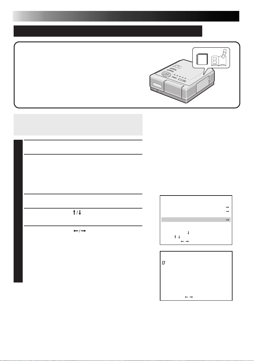
Using This Instruction Manual
• All major sections and subsections are listed in the
Table Of Contents (
• Notes appear after most subsections. Be sure to read
these as well.
• Basic and advanced features/operation are separated
for easier reference.
It is recommended that you . . .
..... refer to “Controls, Indicators and Connectors”
Z pgs. 10 – 11) and familiarize yourself with
(
button locations, etc. before use.
..... read thoroughly the Safety Precautions and Safety
Instructions that follow. They contain extremely
important information regarding the safe use of
your new Multimedia Printer.
You are recommended to carefully read the
cautions on page 5 before use.
Declaration of Conformity
Model Number : GV-DT3U
Trade Name : JVC
Responsible party : US JVC CORP.
Address : 1700 Valley Road
Telephone Number : (973) 315–5000
This device complies with Part 15 of FCC Rules.
Operation is subject to the following two conditions:
(1) This device may not cause harmful
interference, and (2) this device must accept any
interference received, including interference that
may cause undesired operation.
Z pg. 9).
Wayne, N.J. 07470
SAFETY
PRECAUTIONS
CAUTION
RISK OF ELECTRIC SHOCK
DO NOT OPEN
CAUTION: TO REDUCE THE RISK OF ELECTRIC SHOCK.
DO NOT REMOVE COVER (OR BACK).
NO USER-SERVICEABLE PARTS INSIDE.
REFER SERVICING TO QUALIFIED SERVICE PERSONNEL.
The lightning flash with arrowhead symbol, within an
equilateral triangle, is intended to alert the user to the
presence of uninsulated "dangerous voltage" within the
product's enclosure that may be of sufficient magnitude
to constitute a risk of electric shock to persons.
The exclamation point within an equilateral triangle is
intended to alert the user to the presence of important
operating and maintenance (servicing) instructions in
the literature accompanying the appliance.
The GV-DT3 Multimedia Printer should be used with:
AC 120 V`, 60 Hz
To prevent electric shock and hazards, DO NOT use
any other power source.
CAUTION
TO PREVENT ELECTRIC SHOCK MATCH WIDE
BLADE OF PLUG TO WIDE SLOT, FULLY INSERT.
ATTENTION
POUR ÉVITER LES CHOCS ÉLECTRIQUES,
INTRODUIRE LA LAME LA PLUS LARGE DE LA FICHE
DANS LA BORNE CORRESPONDANTE DE LA PRISE
ET POUSSER JUSQU’AU FOND.
Change or modifications not approved by the party
responsible for compliance could void the user’s
authority to operate the equipment. This equipment has
been tested and found to comply with the limits for a
Class B digital device, pursuant to Part 15 of the FCC
Rules. These limits are designed to provide reasonable
protection against harmful interference in a residential
installation. This equipment generates, uses, and can
radiate radio frequency energy and, if not installed and
used in accordance with the instructions, may cause
harmful interference to radio communications.
However, there is no guarantee that interference will
not occur in a particular installation. If this equipment
does cause harmful interference to radio or television
reception, which can be determined by turning the
equipment off and on, the user is encouraged to try to
correct the interference by one or more of the following
measures:
Reorient or relocate the receiving antenna.
Increase the separation between the equipment and
receiver.
Connect the equipment into an outlet on a circuit
different from that to which the receiver is connected.
Consult the dealer or an experienced radio/TV
technician for help.
WARNING:
TO PREVENT FIRE OR SHOCK
HAZARD, DO NOT EXPOSE
THIS UNIT TO RAIN OR
MOISTURE.
NOTE:
The rating plate (serial number plate) and safety
caution are on the bottom and/or the back of the main
unit.
This Class B digital apparatus meets all requirements of
the Canadian Interference – Causing Equipment
Regulations.
“Cet appareil numérique de la classe B respecte toutes
les exigences du Règlement sur le matériel brouilleur
du Canada.”
Page 3

IMPORTANT PRODUCT
SAFETY INSTRUCTIONS
Electrical energy can perform many useful functions. But
improper use can result in potential electrical shock or fire
hazards. This product has been engineered and
manufactured to assure your personal safety. In order not to
defeat the built-in safeguards, observe the following basic
rules for its installation, use and servicing.
ATTENTION:
Follow and obey all warnings and instructions marked on
your product and its operating instructions. For your safety,
please read all the safety and operating instructions before
you operate this product and keep this manual for future
reference.
INSTALLATION
1. Grounding or Polarization
(A) Your product may be equipped with a polarized
alternating-current line plug (a plug having one blade
wider than the other). This plug will fit into the power
outlet only one way. This is a safety feature.
If you are unable to insert the plug fully into the outlet,
try reversing the plug. If the plug should still fail to fit,
contact your electrician to replace your obsolete
outlet. Do not defeat the safety purpose of the
polarized plug.
(B) Your product may be equipped with a 3-wire
grounding-type plug, a plug having a third (grounding)
pin. This plug will only fit into a grounding-type power
outlet. This is a safety feature.
If you are unable to insert the plug into the outlet,
contact your electrician to replace your obsolete
outlet. Do not defeat the safety purpose of the
grounding-type plug.
2. Power Sources
Operate your product only from the type of power source
indicated on the marking label. If you are not sure of the
type of power supply to your home, consult your product
dealer or local power company. If your product is intended
to operate from battery power, or other sources, refer to the
operating instructions.
3. Overloading
Do not overload wall outlets, extension cords, or integral
convenience receptacles as this can result in a risk of fire or
electric shock.
4. Power Cord Protection
Power supply cords should be routed so that they are not
likely to be walked on or pinched by items placed upon or
against them, paying particular attention to cords at plugs,
convenience receptacles, and the point where they exit
from the product.
3
5. Ventilation
Slots and openings in the cabinet are provided for
ventilation. To ensure reliable operation of the product and
to protect it from overheating, these openings must not be
blocked or covered.
• Do not block the openings by placing the product on a
bed, sofa, rug or other similar surface.
• Do not place the product in a built-in installation such as
a bookcase or rack unless proper ventilation is provided
or the manufacturer’s instructions have been adhered to.
6. Wall or Ceiling Mounting
The product should be mounted to a wall or ceiling only as
recommended by the manufacturer.
Page 4

4
USE
1. Accessories
To avoid personal injury:
• Do not place this product on an unstable cart, stand,
tripod, bracket or table. It may fall, causing serious injury
to a child or adult, and serious damage to the product.
• Use only with a cart, stand, tripod, bracket, or table
recommended by the manufacturer or sold with the
product.
• Use a mounting accessory recommended by the
manufacturer and follow the manufacturer’s instructions
for any mounting of the product.
• Do not try to roll a cart with small casters across
thresholds or deep-pile carpets.
2. Product and Cart Combination
A product and cart combination
should be moved with care.
Quick stops, excessive force, and
uneven surfaces may cause the
product and cart combination to
overturn.
3. Water and Moisture
Do not use this product near
water—for example, near a bath
tub, wash bowl, kitchen sink or laundry tub, in a wet
basement, or near a swimming pool and the like.
4. Object and Liquid Entry
Never push objects of any kind into this product through
openings as they may touch dangerous voltage points or
short-out parts that could result in a fire or electric shock.
Never spill liquid of any kind on the product.
5. Attachments
Do not use attachments not recommended by the
manufacturer of this product as they may cause hazards.
6. Cleaning
Unplug this product from the wall outlet before cleaning.
Do not use liquid cleaners or aerosol cleaners. Use a damp
cloth for cleaning.
7. Heat
The product should be situated away from heat sources
such as radiators, heat registers, stoves, or other products
(including amplifiers) that produce heat.
PORTABLE CART WARNING
(Symbol provided by RETAC)
SERVICING
1. Servicing
If your product is not operating correctly or exhibits a
marked change in performance and you are unable to
restore normal operation by following the detailed
procedure in its operating instructions, do not attempt to
service it yourself as opening or removing covers may
expose you to dangerous voltage or other hazards. Refer all
servicing to qualified service personnel.
2. Damage Requiring Service
Unplug this product from the wall outlet and refer servicing
to qualified service personnel under the following
conditions:
a. When the power supply cord or plug is damaged.
b. If liquid has been spilled, or objects have fallen into the
product.
c. If the product has been exposed to rain or water.
d. If the product does not operate normally by following
the operating instructions. Adjust only those controls that
are covered by the operating instructions as an improper
adjustment of other controls may result in damage and
will often require extensive work by a qualified
technician to restore the product to its normal operation.
e. If the product has been dropped or damaged in any way.
f. When the product exhibits a distinct change in
performance—this indicates a need for service.
3. Replacement Parts
When replacement parts are required, be sure the service
technician has used replacement parts specified by the
manufacturer or have the same characteristics as the
original part. Unauthorized substitutions may result in fire,
electric shock or other hazards.
4. Safety Check
Upon completion of any service or repairs to this product,
ask the service technician to perform safety checks to
determine that the product is in safe operating condition.
Page 5

CAUTIONS
5
If you notice smoke or a peculiar smell coming from
the printer, shut it down and unplug it
IMMEDIATELY. Use of the
printer under these
conditions could lead to fire
or electric shock. Contact
your JVC dealer. DO NOT
attempt to repair the
malfunction yourself.
DO NOT attempt to insert foreign objects into the
printer, as this can lead to
electric shock or fire. If an
object other than print paper
is accidentally inserted, shut
the printer down, unplug it
and contact your JVC dealer.
Exercise caution when moving the printer. If you
drop the unit, do not attempt
to use it. If during use you
notice that the cabinet is
damaged, shut the printer
down, unplug it and contact
your JVC dealer. Use of the
printer under these conditions
can lead to fire or electric
shock.
DO NOT place heavy objects on the printer’s
power cord, or leave the cord near any heatgenerating appliance, as this can
damage the cord. Avoid
excessive pulling or twisting of
the power cord. If the power
cord becomes cut or otherwise
damaged, contact your JVC
dealer. When unplugging the
printer, DO NOT pull on the
cord. Hold the plug itself and
remove it from the AC outlet.
Use of the printer with a
damaged power cord can lead
to fire, electric shock and unit
malfunctions.
DO NOT remove the cover and attempt to repair or
modify the printer. There are
high-voltage components
within the unit, and the risk
of electric shock and unit
malfunctions exists. If a
problem occurs, contact your
JVC dealer.
ABOUT THERMAL HEADS
•The thermal heads, necessary for printing, are located
within the unit. The heads can become extremely
warm. To prevent possible burns and injuries, do not
touch the thermal heads.
•When the printer is used for extended periods, the
thermal heads experience wear and tear just like VCR
heads. As the thermal heads become worn, print
quality will gradually decrease. When you notice a
decline in quality, it is possible that the heads may
need to be replaced. Consult your JVC dealer.
MOISTURE CONDENSATION
If condensation occurs inside the printer, it may adhere
to print paper during printing, causing poor quality
prints and paper jams. If you think condensation may
exist within the unit, let the unit sit for at least 2 hours
(with the power on) to dry sufficiently. If paper is stuck
within the unit, remove it before turning the power on.
Unused print paper subjected to moisture should not
be used for printing.
•Condensation may occur in the following situations:
1) In a room when the heater suddenly comes on;
2) In the direct path of cool air from an air
conditioner;
3) When the unit is moved from a cool place to a
warm place.
DUST
Due to dust or lint adhering to print paper, or to
extreme variations in temperature, a small degree of
color smearing or lines may be visible in prints.
Failure to heed the following precautions may
result in damage to the printer.
1. DO NOT place the printer . . .
... in an environment prone to extreme temperatures
or humidity.
... in direct sunlight.
... in a dusty environment.
... in an environment where strong magnetic fields
are generated.
... on a surface that is unstable or subject to
vibration.
2.
DO NOT block the printer’s ventilation openings.
3.
DO NOT place heavy objects on the printer.
4.
DO NOT place anything which might spill on top of
the printer.
5.
AVOID violent shocks to the printer during
transport.
Make sure that you have easy access to the AC
outlet which the printer
is plugged into so that it
can be immediately
unplugged in case of
emergency. Connect the
printer power plug to a
different AC outlet from
the TV and VCR.
CAUTION:
Changes or modifications not approved by JVC
could void user’s authority to operate the
equipment.
Page 6

6
EXACT FRAME FUNCTION
You can choose the exact image you want
from 54 frames shown in the index window,
perfect for when you miss the right moment to
press the MEMORY button.
PICTURE PROCESSOR FUNCTION
A built-in image processor offers a variety of
special effects such as Auto Picture Adjustment,
Clear Black, Back-Lit Compensation, B/W and
Sepia. Manual adjustment is also possible.
MAJOR FEATURES
PICTURE MEMORY FUNCTION
Store your favorite images in the printer’s
memory for repeated printing, even after the
power has been tuned off.
Page 7

A Variety of Special Effects Printing Optionss
This printer allows you to print text or images on standard paper, seal paper or transparent film
in any of one of several formats.
STORED TITLE IMPOSE (Z page 31)
Print with titles.
STORED FRAME IMPOSE (Z page 32)
Print with frames.
7
Page 8

8
MAJOR FEATURES (cont.)
MULTI-PRINT OF SAME IMAGE
(Z page 24)
Print 2, 4 or 16 of the same image on
one sheet.
STROBE PRINT (Z page 26)
Print at set intervals, as when taking
snapshots in rapid succession.
MULTI-PRINT OF DIFFERENT
IMAGES (Z page 25)
Print 2, 4 or 16 different images on
one sheet.
CALENDAR PRINT
(Z page 27)
OCT. 1999
TUE
WED
THU
SUN
MON
3
4
10
11
17
18
24
25
31
FRI
1
5
6
7
8
12
13
14
15
19
20
21
22
26
27
28
29
SAT
2
9
16
23
30
TRIMMING PRINT (Z page 28)
Cut out a particular part of an image
and enlarge it for printing.
ROTATING/REVERSING IMAGES
(Z page 30)
Rotate an image 90°/180°, or reverse
it to create a mirror image.
BUILT-IN CAPTURE FACILITY (Z page 38)
Images stored in the printer can be transferred to your computer using the provided
image transfer software. The transferred images can be processed or printed using
commercially available software.
Page 9

CONTENTS
MAJOR FEATURES
CONTROLS, INDICATORS AND CONNECTORS
PREPARATION
INSTALLATION OF INK CASSETTE
LOADING THE PAPER TRAY
HOW TO MAKE CONNECTIONS (CABLE CONNECTION)
HOW TO MAKE CONNECTIONS [IrDA (IrTran-P) RECEPTION]
PRINTING FROM A DIGITAL CAMCORDER/S-VHS VCR
(CABLE CONNECTION)
PRINTING FROM A DIGITAL STILL CAMERA
[IrDA (IrTran-P) RECEPTION]
DIFFERENT TYPES OF PRINTING
9
6
10
12
14
15
16
17
18
20
22
CONVENIENT FUNCTIONS
TROUBLESHOOTING
SPECIFICATIONS
INDEX
FOR SERVICING
WARRANTY
PROVIDED ACCESSORIES
DV Cable
S-Video Cable
CD-ROM
Paper Tray
● It should be noted that it may be unlawful to print from pre-recorded tapes or discs without
the consent of the owner of copyright in the video recording, broadcast or cable program
and in any literary, dramatic, musical, or artistic work embodied therein.
● The copyright for the program which provides IrDA (IrTran-P) infrared communications for
this software is owned by Okaya Systemware Co., Ltd.
IrDA (IrTran-P) Protocol Stack Deep Core™ Okaya Systemware Co., Ltd.
Color Print Paper Sheet Set
•Standard Print Paper (10
sheets)
•Ink Cassette (10 prints)
•Picture Navigator
• Mr. Photo
• PhotoAlbum
• ImageFolio
Video Cable x 2
PC Connection Cable
x 1 for Windows® PC
PC Connection Cable
x 1 for Macintosh
®
33
39
46
47
48
49
Page 10

10
1
e
r
t
y
u
4
5
3
2
6
CONTROLS, INDICATORS AND CONNECTORS
Front View
Rear View
1 IrDA (IrTran-P) sensor
• Receives video data through the IrDA
(IrTran-P) communication system.
2 VIDEO INPUT connector
• Connect to the source unit’s normal
video output using the provided video
cable.
3 S-Video INPUT connector
• Connect to the source unit’s S-Video
output using the provided S-Video cable.
4 DV IN connector
• Used to receive video data from a digital
camcorder with a DV connector using
the provided DV cable.
5 Paper Tray Access Door
• Open this to insert the paper tray.
6 Ink Cassette Access Door
• Open this to load or unload the ink
cassette.
7 POWER button
• Turns the printer on and off.
8 PICTURE PROCESSOR button
• Press to use the Picture Processor
function.
9 OK button
• Press to enter menu settings.
0 DV lamp
• Lights when a source unit’s DV output is
connected to the DV IN connector using
the provided DV cable and the DV
mode is selected.
! IrDA (IrTran-P) lamp
• Lights when receiving video data
through the IrDA (IrTran-P)
communication system from an IrDAcompatible digital camcorder.
@ VIDEO lamp
• Lights when a source unit’s video output
is connected to the VIDEO INPUT
connector using the provided video
cable and the VIDEO mode is selected.
# PC lamp
• Lights when a computer is connected to
the PC connector and the PC mode is
selected for manipulation of printer
images.
$ EXACT FRAME lamp
• Lights when the EXACT FRAME button is
pressed to use the Exact Frame function.
% EXACT FRAME button
• Press to use the Exact Frame function.
Page 11

%
^
&
POWER
EXACT
PROCESSOR
FRAME
MENU OK
PICTURE
7
8
9
! @ # $
IrDA (IrTran-P)
SOURCE/
VIDEO PC EXACT FRAME
MEMORY PRINT
FRAME STABILIZER
( ) q w
DV
INPUT
SELECT
*
0
STORED IMAGE
11
^ MENU button
• Press to access the MENU screen.
& Cursor buttons
• Use to make selections during menu
operation.
* INPUT SELECT button
• Press to select the video data input mode.
( SOURCE/STORED IMAGE button
• Press to switch between input and stored
display.
) MEMORY/FRAME STABILIZER button
• Press to store an image for printing.
• Press to stabilize the frame of an unstable
image.
q PRINT button
Press to print an image.
w PRINT lamp
• Lights when video data are being stored
in the printer and blinks while the printer
is printing an image or receiving video
data.
e Vent holes
• Provided for ventilation to protect the
unit from overheating; do NOT block or
cover them.
r Service Door for Jammed Paper Removal
• Open this door when paper is jammed.
* Do not open this door unless paper is
jammed. Be sure to close this after
clearing the paper jam.
t PC Connector
• Connect to a computer using the provided PC connection cable.
y Video Output Connector
• Using a video cable, connect the printer
to a television.
u Power Cord
• Plug into an AC outlet. Be sure to press
the POWER button to turn off the power
before unplugging the power cord.
Page 12

12
● Before printing, make sure everything is set up and ready.
1
Have a Color Print Paper Sheet Set ready (page 13).
2
Install the ink cassette in the printer (page 14).
3
Place the color print paper sheets in the paper tray and load the
tray (page 15).
● Use the print sheets and ink cassette from the same kit.
4
Connect an image source to the printer (page 16).
5
Plug the printer’s power cable into an AC outlet and press the
POWER button.
● Power comes on and the POWER indicator lights.
PREPARATION
You are now ready to print. For specific printing instructions,
read the page corresponding to the type of printing you
want to do (pages 18 through 37).
Page 13

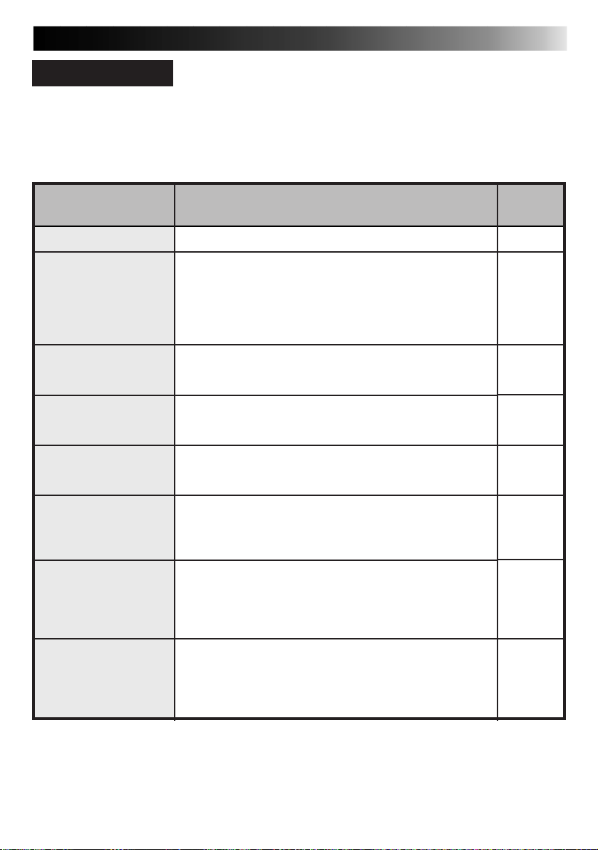
About Color Print Paper Sheet Sets (optional)
You must use one of the sets shown in the following chart:
13
SET
PV-50SFAU
(Standard type)
PV-25SFSAU
(Sticker type)
PV-25UFAU
(Glossy type)
● If printing on a PV-25SFSAU print sheet, the image may be slightly offset from its proper
position.
Before Printing
● Do not touch the printing side of the paper.
● Do not use paper that is torn or curled, as
this can result in paper jamming.
● Do not use paper that is wet or damp.
Printing may not be possible and paper
jamming may occur.
● Do not touch or pull out the ink cassette’s
ink sheet.
● Keep young children away from the ink
cassette’s ink sheet.
● When the ink cassette is empty, replace it
with a new one. An empty ink cassette
cannot be used. Do not try to rewind and
re-use cassette.
● Do not expose the paper to high temperatures, high humidity and/or direct sunlight.
● You can write on the back side of a PV50SFAU print sheet.
● If you want to write something or stick a
stamp on a PV-50SFAU sheet, wait until
printing is finished. If you write something
or stick something on before printing, the
printer may not work properly.
● Carefully read the precautions in the color
print paper sheet set box and on the back of
the color print paper sheet set before using.
• Standard Print Paper (50 Sheets)
• Ink Cassette (50 Prints)
• Sticker Print Paper (25 Sheets)
• Ink Cassette (25 Prints)
• Super-Fine High Grade Paper
(25 Sheets)
• Ink Cassette (25 Prints)
CONTENTS
USES
Print your favorite images, just like
snapshots.
Make customized seals and stick
them on greeting cards, envelopes,
letters, etc.
Make customized picture postcards,
greeting cards, etc. with less color
fading compared to standard paper.
After Printing
● If you touch a fresh print with wet hands,
the print image may be discolored.
● If a print absorbs organic cleaning solvents
(alcohol, ester, keton, etc.), the colors will
fade.
● If cellophane tape or soft PVC are affixed to
a print, the chemical reaction will cause
accelerated color fading.
● When writing on a PV-50SFAU print sheet,
be sure to use a pencil or an oil-based
writing utensil. If you apply too much
pressure, you’ll leave imprints on the print
sheet.
Storage
● Avoid storing prints in areas subject to high
temperatures or humidity, or near a heater
or heat-generating device.
● Do not store prints in a soft plastic folder.
Accelerated color fading may result due to
the chemical reaction, or the print(s) may
stick to the file.
● Do not store 2 prints with the printed sides
touching, as the sheets may stick together.
● Store print paper in its box, on a level
surface. Failure to do so may cause the print
paper to curl or bend, which can result in a
paper jam within the unit.
Page 14

14
mark
INSTALLATION OF INK CASSETTE
Install the ink cassette included with the optionally
available color print paper sheet set.
OPEN CASSETTE DOOR
1
Pull the right top of the door in the direction
indicated by the arrow to open it.
TAKE UP SLACK
2
Turn the roller on the side with the mark
in the direction of the arrow.
Do not turn the part marked with
INSTALL INK CASSETTE
3
Insert the cassette label-side up from the end
A
marked. Push it until you hear a click.
CLOSE CASSETTE DOOR
4
Push the right side of the door.
•The door clicks when it is fully closed.
A
.
When removing ink cassette
Push the lock lever in the direction of the arrow.
The ink cassette is unlocked and can be removed.
CAUTION
Do not stick your fingers into the ink cassette
storage space. You may be burned or injured.
Page 15

LOADING THE PAPER TRAY
A
To printer
Detection marks
Printing side
Partition panel
15
Opening the paper tray
● Open the lid while pushing A.
Inserting color print paper sheets in
the paper tray
With Standard/Sticker Print Paper
1. Keep the partition panel upright. If it is
down or tilted, push it back to the upright
position.
2. Load print sheets in the tray, placing the
sides with the detection marks or printing
toward the printer face down.
•The tray can hold up to 25 sheets at one
time.
With Super-Fine High Grade Paper
1. Push down the partition panel.
2. Load print sheets in the tray in the same
way as Standard/Sticker Print Paper.
•The tray can hold up to 25 sheets at one
time.
● Shuffle print paper sheets thoroughly to
separate each sheet before placing them in
the paper tray.
● Be sure to read the precautions on the paper
tray lid.
Loading/unloading the paper tray
● When loading, push the tray until it clicks.
● When unloading, push the tray slightly to
unlock the latch, then pull it out.
Page 16

16
HOW TO MAKE CONNECTIONS (CABLE CONNECTION)
WHEN PRINTING FROM A DIGITAL CAMCORDER WITH A DV CONNECTOR OR A VCR
WITH AN S-VIDEO OUTPUT CONNECTOR
Make sure that you have easy access to the AC outlet which the printer is plugged into so that it
can be immediately unplugged in case of emergency. Connect the printer power plug to a
different AC outlet from the TV and VCR.
Printer
Connect to
video input
connector
TV (set to VIDEO
(EXT. input) mode)
Image source with S-Video
output connector
When you’re using a digital
camcorder, connect it to the
printer using both the provided
DV cable and a video cable in
order to monitor the source tape
on the TV screen.
Connect to
video output
connector
Video cable
(provided)
Connect to video
input connector
S-Video cable
(provided)
Connect to image source
S-Video output connector
Digital camcorder
Rear
connectors
Front
connectors
Connect to DV input connector
Connect to S-Video
input connector
DV cable (provided)
Audio/video cable
AV OUT
MIC IN
Be sure to carefully review the instruction manuals for all the units that you will be using in conjunction with this printer.
Some televisions and video cassette recorders require a specific type of output cable. Refer to their
instruction manuals for details on television and VCR connections to the printer.
The printer assigns priority to input signals.
S-video signals take priority over regular video signals.
When you use an LCD video camera with a printer input connector:
When you connect the output of a camcorder equipped with an LCD monitor to the printer, you can
view the printer’s output image on the LCD monitor. Refer to the camcorder’s instruction manual for
connection details.
Page 17
HOW TO MAKE CONNECTIONS [IrDA (IrTran-P) RECEPTION]
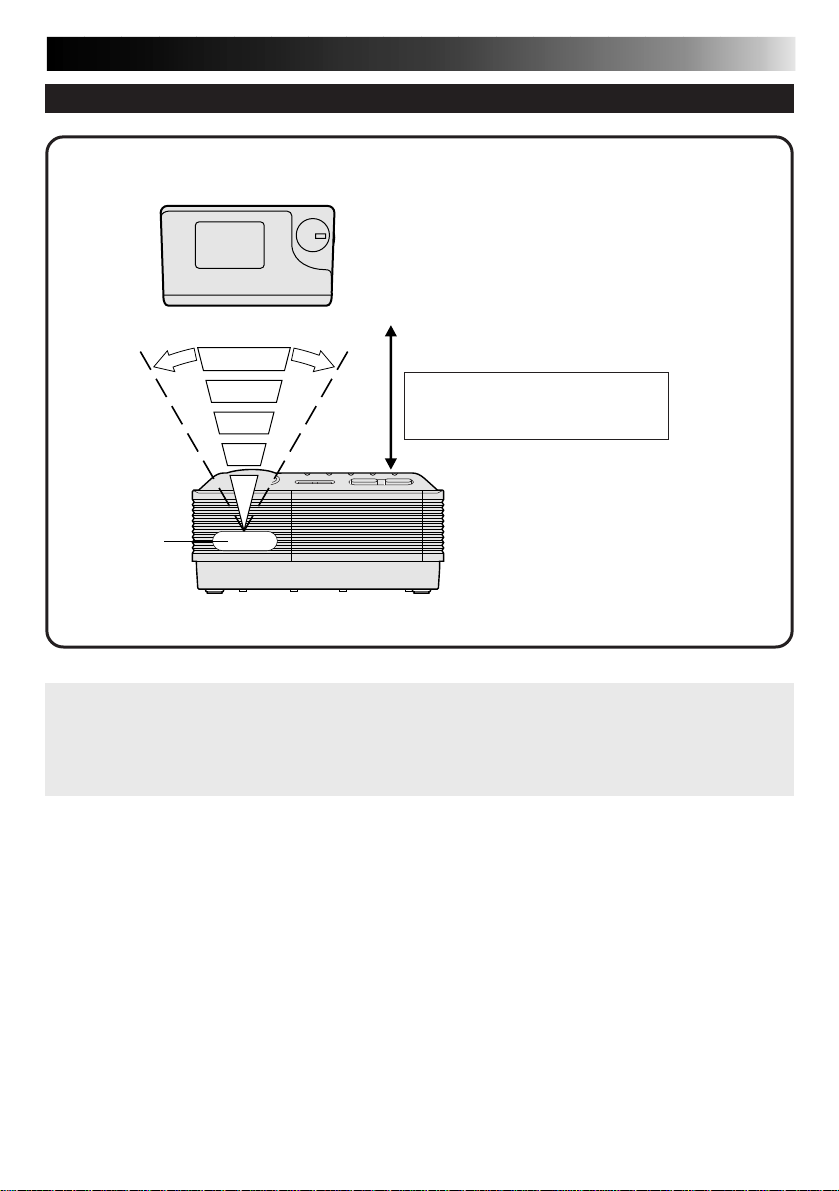
WHEN PRINTING FROM AN IrTran-P COMPATIBLE DIGITAL STILL CAMERA
IrTran-P compatible
digital still camera
17
Approx. 15&
IrDA (IrTran-P)
sensor
Printer
Video data communications with the IrDA (IrTran-P) infrared communications system can
be accomplished only between one transmitter and one receiver.
If a picture is sent from one digital still camera to more than one printer, the picture can be
received and printed only by the printer that has first responded to the transmission.
Approx. 15&
Within a distance of approximately 19”
Data communications may not be
possible between some units when
they are too close or too distant.
IrTran-P (Infrared Transfer Picture):
An infrared video data communications
format which enables infrared
communications of video data between
compatible units of different
manufacturers.
Page 18
18
DV
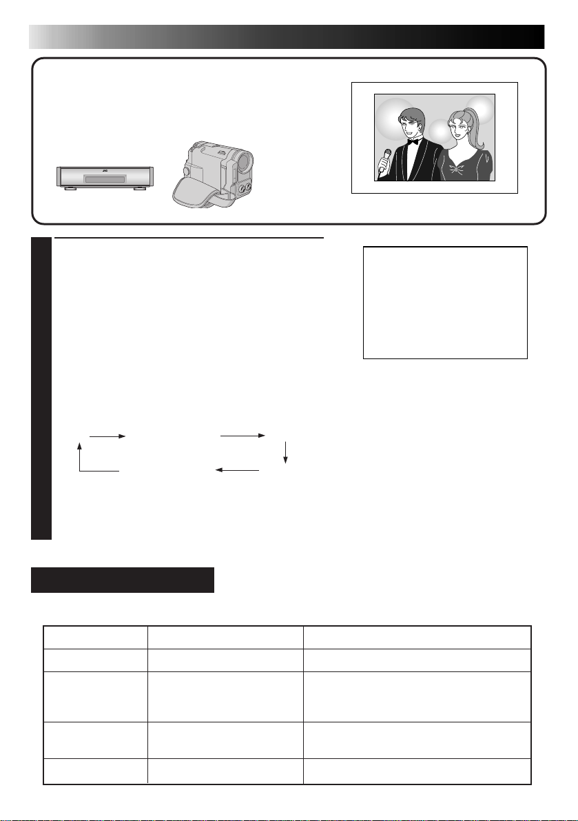
PRINTING FROM A DIGITAL CAMCORDER/S-VHS VCR (CABLE CONNECTION)
This section explains how to print a single image
from a digital camcorder or an S-VHS VCR connected to the printer via a cable.
Preparation
See page 12.
PRESS INPUT SELECT TO SELECT INPUT
1
MODE
•Press INPUT SELECT to select the appropriate
input mode depending on the connector being
used, referring to the indication shown on the
TV screen or the relevant lamps on the printer.
(See Input Mode Selection below.)
When using the DV IN connector, select DV.
When using the S or VIDEO INPUT connector,
select VIDEO.
Pressing the button cycles through the input
modes as follows:
DV
IrDA (INFRARED)
VIDEO
PC MODEPICTURE MEMORY
•If you select DV when a source unit is connected
to the printer’s VIDEO INPUT connector, the
picture input from the VIDEO INPUT connector
appears on the screen.
Input Mode Selection
The video data input mode you need depends on the image source and connection you use.
Input Mode
DV mode
IrDA (INFRARED)
mode
VIDEO mode
PC MODE
DV IN connector
IrDA (IrTran-P) sensor
S INPUT/VIDEO INPUT
connector
PC connector
Connector
Image Source
Digital camcorder
IrTran-P compatible digital still camera
Computer (Infrared Communications
Driver Ver 2.0 compatible)
VCR, camcorder
Computer
Page 19

BEGIN SOURCE PLAYBACK
2
1
PRESS MEMORY WHEN THE
3
DESIRED IMAGE APPEARS
•If the image is unstable, press MEMORY
again.
2
PRESS OK
•If the PRINT lamp does not blink, the video
data has not been properly input to the
printer. Make sure you have a proper
connection and try again.
PRESS PRINT TO START PRINTING
4
If you want to try to stabilize the stored image again ...
press MEMORY again.
If you store the wrong image or an image incorrectly ...
press SOURCE/STORED IMAGE to call up the INPUT display, then find the correct image
and store it in memory. The incorrect image will be deleted and the new image will be
stored.
If you want to print multiple copies of the same scene ...
select the number of print copies on the MENU 1 screen. You can select up to 25 copies
(page 23). If you want to cancel print operation when printing two or more copies, press
MENU. The printer stops print operation after finishing the currently printing page, leaving
REMAINING SHEETS: 1 on the screen. Pressing MENU cancels print operation only when
printing more than one sheet.
If you want to switch between the input image and the stored image ...
press SOURCE/STORED IMAGE. Each time you press the button, the displayed image
alternates between the input image and the stored image. Once you press OK in step
cannot restore the original input image. This function is not available during printing.
To print a live image using a camcorder as the source ...
in step
2
, instead of playing back the source tape, engage the camcorder’s Record mode.
An image taken from video processed with special effects may not be printed properly.
If the image you want to print is from video processed with effects such as squeeze or
cinema, it may not be printed properly.
The stored image looks overly bright on the screen.
If the stored image looks overly bright on the screen, it will not affect the actual print; the
image will be printed properly.
The printed image is different from the one selected on the screen.
There may be cases where the printed image is different from the one selected on the screen.
If you want to print an image shot vertically with a camcorder ...
make sure that the upper part of the image is facing the left of the screen. If the upper part of
the image is facing the right of the screen, rotate the image 180° and print it.
(
Z steps
3
– 7 on page 30)
3
, you
19
Page 20
20
IrDA
(INFRARED)
When using a digital still camera compatible with IrTran-P,
refer also to the instruction manual provided with the
camera.
1
2
PRINTING FROM A DIGITAL STILL CAMERA [IrDA (IrTran-P) RECEPTION]
This section explains how to print an image
transmitted from an IrDA (IrTran-P) compatible
digital still camera using infrared communication.
Preparation
See page 12.
PRESS INPUT SELECT TO SELECT IrDA
MODE
•If you select IrDA (INFRARED) when a source
unit is connected to the printer’s VIDEO INPUT
connector, the picture input from the VIDEO
INPUT connector appears on the screen.
TRANSMIT THE PICTURE IN THE
CAMERA TO THE PRINTER
•Aim the digital still camera’s IrDA (IrTran-P)
transmitter at the printer’s IrDA (IrTran-P) sensor.
•The picture data is sent from the digital still
camera to the printer.
•The IrDA lamp blinks while the video data are
being transmitted to the printer, and RECEIVING
TRANSMISSION appears on the screen.
WHEN THE PRINT LAMP LIGHTS,
3
PRESS PRINT TO START PRINTING
Page 21

21
● Refer to the instruction manuals provided with the machines in use for details of their
operation.
● If you want to transmit the stored picture to your computer, refer to the instruction manual
of the provided image transfer software.
● Data communications may be variable or impossible depending on the lighting condition,
battery consumption, communications distance and sending and receiving angles.
● If you want to print an image shot vertically with a digital still camera, make sure that the
upper part of the image is facing the left of the screen. If the upper part of the image is facing
the right of the screen, rotate the image 180° and print it. (
Z steps
3
– 7 on page 30)
Page 22
22
MENU 1 1/2
NUMBER
OF PRINTS: 1
ON SCREEN:.ON OFF
PRINT TYPE : .STANDARD
:
MULTI
:
CALENDAR
:
LAYOUT
TO MENU 2
[ ]
ITEM
[
/
]
OK [OK]
SELECT
[
/
]
QUIT [MENU]
LAYOUT
.VERTICAL
HORIZONTAL
ITEM
[
/
]
OK [OK]
QUIT [MENU]
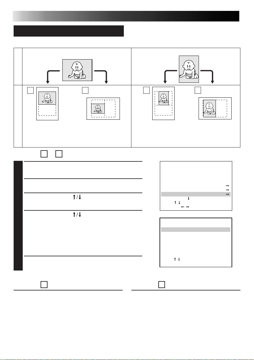
POSTCARD/GREETING CARD PRINT
There are 4 different types of layout for printing.
Horizontal
Stored image
DIFFERENT TYPES OF PRINTING
Vertical
1 2
Layout
Vertical layout
(full width)
For Layout 1 or 4
Horizontal layout
(smaller size with blank
portion at the top and
bottom of the image)
STORE AN IMAGE YOU WANT TO
1
PRINT
PRESS MENU
2
PRESS CURSOR TO SELECT
3
LAYOUT, THEN PRESS OK
PRESS CURSOR TO SELECT
4
VERTICAL OR HORIZONTAL, THEN
PRESS OK
•The image you want to print will be stored in
memory.
•The original input image cannot be restored.
PRESS PRINT TO START PRINTING
5
3 4
Vertical layout
(smaller size with blank
portion at the right and
left sides of the image)
Horizontal layout
(full height)
For Layout 2
1 Store the image you want to print and rotate
the image 90& counterclockwise (L90&) on
EFFECT SET MENU (
30).
2 Perform steps
Z steps
2
– 5 described above.
3
– 7 on page
For Layout 3
1 Store the image you want to print and
rotate the image 90° clockwise (R90&) on
EFFECT SET MENU (
30).
2 Perform steps
Z steps
2
– 5 described above.
3
– 7 on page
Page 23

Number of Print Copies
MENU 1 1/2
NUMBER
OF PRINTS: 16
ON SCREEN:.ON OFF
PRINT TYPE : .STANDARD
:
MULTI
:
CALENDAR
:
LAYOUT
TO MENU 2
[ ]
ITEM
[
/
]
OK [OK]
SELECT
[
/
]
QUIT [MENU]
MENU 1 1/2
NUMBER
OF PRINTS: 1
ON SCREEN:.ON OFF
PRINT TYPE : .STANDARD
:
MULTI
:
CALENDAR
:
LAYOUT
TO MENU 2
[ ]
ITEM
[
/
]
OK [OK]
SELECT
[
/
]
QUIT [MENU]
MENU 2 2/2
EFFECT
TITLE
FRAME
QUALITY :
.STD HIGH
PICTURE MEMORY
TO MENU 1
[ ]
ITEM
[
/
]
OK [OK]
SELECT
[
/
]
QUIT [MENU]
● Press Cursor to select from 1 up to 25.
ON SCREEN Display
● ON : Usually set to ON.
● OFF : Set to OFF when the on-screen display and
the stored image are superimposed upon
one another, making the screen difficult to
view.
Print Quality
● STD : Print at 153 dpi (faster than HIGH).
● HIGH : Print at 306 dpi for better quality.
23
• If STD is selected, the picture quality will not be as
good as that of HIGH.
• Be sure to set QUALITY before you store the
image you want to print.
• If you repeatedly print images at different print
speeds, it will cause the picture quality to
deteriorate.
● Press Cursor repeatedly to switch between the MENU 1 and MENU 2 screens.
● When setting more than 1 item on a MENU screen, you do not have to exit the MENU
screen each time; simply use the cursor button
entering a setting.
to select another item after you finish
Page 24
24
MENU 1 1/2
NUMBER
OF PRINTS: 1
ON SCREEN:.ON OFF
PRINT TYPE : .STANDARD
:
MULTI
:
CALENDAR
:
LAYOUT
TO MENU 2
[ ]
ITEM
[
/
]
OK [OK]
SELECT
[
/
]
QUIT [MENU]
MULTI PIX MENU
MULTI
:
16
CONTENT : SAME PIX
ITEM
[
/
]
OK [OK]
SELECT
[
/
]
QUIT [MENU]
DIFFERENT TYPES OF PRINTING (cont.)
MULTI-PRINT (SAME SCENE)
You can print the same image 2, 4 or 16 times on
one sheet.
Preparation
● See page 12.
● Press INPUT SELECT to select the appropriate input
mode depending on the connection to the source unit.
(Z page 18).
PRESS MENU
1
PRESS CURSOR TO SELECT MULTI,
2
THEN PRESS OK
PRESS CURSOR TO SELECT THE
3
NUMBER OF IMAGES ON MULTI,
THEN PRESS OK
PRESS CURSOR TO SELECT SAME
4
PIX ON CONTENT, THEN PRESS OK
•If IrDA (INFRARED) or PC MODE is selected, you do
not have to perform steps 5 and 6. Refer to page 20 or
38 to send the image you want to print to the printer.
BEGIN SOURCE PLAYBACK
5
1
PRESS MEMORY WHEN THE
6
DESIRED IMAGE APPEARS
•If the image is unstable, press MEMORY
again.
2
PRESS OK
•The processed image will be stored in
memory.
PRESS PRINT TO START
7
PRINTING
Page 25
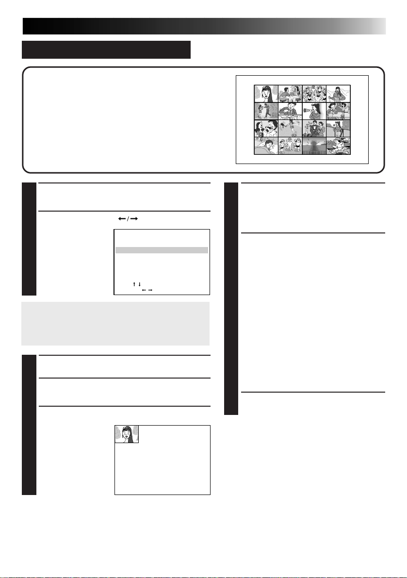
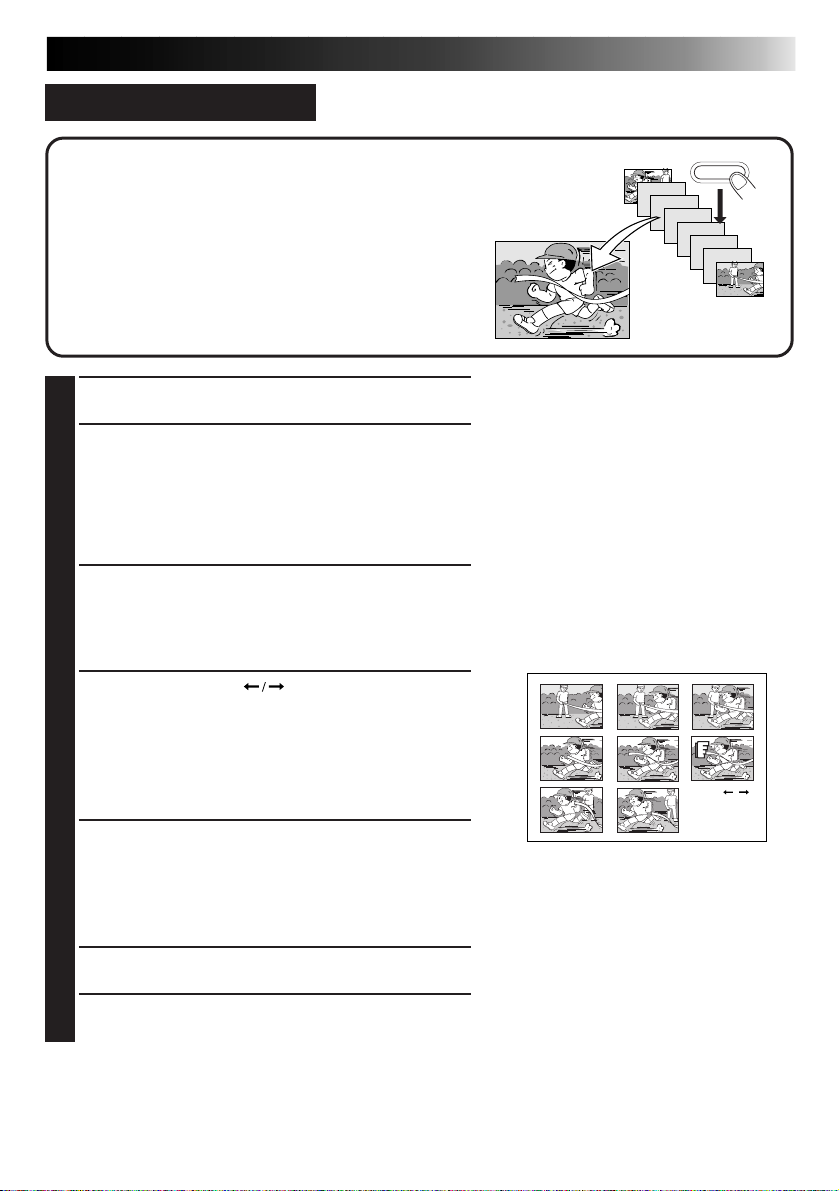
MULTI-PRINT (DIFFERENT SCENES)
You can print various images (your choice of 2, 4
or 16) on the same print sheet.
Preparation
● See page 12.
● Press INPUT SELECT to select the appropriate input
mode depending on the connection to the source unit
(Z page 18).
25
PERFORM STEPS 1 – 3 ON PAGE
1
24
PRESS CURSOR TO SELECT
2
SELECTED PIX
ON
CONTENT,
THEN PRESS
OK
•If IrDA (INFRARED) or PC MODE is selected, you
do not have to perform steps 3 and 4. Refer to page
20 or 38 to send the image you want to print to the
printer.
BEGIN SOURCE PLAYBACK
MULTI PIX MENU
MULTI
CONTENT : SELECTED PIX
ITEM
SELECT
:
16
[
]
/
[
/ ]QUIT [MENU]
3
PRESS MEMORY WHEN THE
4
DESIRED IMAGE APPEARS
PRESS OK
5
•The stored
image will be
displayed in the
top left corner of
the screen.
OK [OK]
PRESS SOURCE TO CALL UP
6
THE INPUT DISPLAY
•The screen switches from the stored
to the input display.
REPEAT STEPS 4 AND 6 FOR
7
EACH IMAGE YOU ARE
GOING TO PRINT (2, 4 OR
16) AND STORE THEM
•If you want to cancel the multi-print
operation midway, press MENU.
After MULTI-IMAGE COMPLETED
ADDITIONAL IMAGES MAY NOT
BE ADDED PLEASE WAIT is
displayed on the screen, the MENU
screen appears. Press MENU to exit.
•Even if you have not yet stored the
selected number of images in
memory, you can still print the
images already stored.
PRESS PRINT TO START
8
PRINTING
Page 26

26
MULTI PIX MENU
MULTI
:
16
CONTENT : STROBE
ITEM
[
/
]
OK [OK]
SELECT
[
/
]
QUIT [MENU]
DIFFERENT TYPES OF PRINTING (cont.)
STROBE PRINT
The printer stores a selected number of images at
short intervals, then prints them on one sheet.
Preparation
See page 12.
PRESS INPUT SELECT TO SELECT VIDEO
1
INPUT MODE
PERFORM STEPS 1 – 3 ON PAGE 24
2
PRESS CURSOR TO SELECT
3
STROBE ON CONTENT
PRESS OK
4
BEGIN SOURCE PLAYBACK
5
PRESS MEMORY WHEN THE DESIRED
6
IMAGE APPEARS
•The selected number of images will be stored at
short intervals.
PRESS OK
7
PRESS PRINT TO START PRINTING
8
● When STROBE is selected, if you press INPUT SELECT to select DV and press MEMORY,
STROBE PRINT IS SELECTED SWITCH INPUT SELECT TO VIDEO appears on the
screen.
Page 27
27
CALENDAR SET
YEAR: 1999
MONTH : OCT
LAYOUT : VERTICAL
ITEM
[
/
]
OK [OK]
SELECT
[
/
]
QUIT [MENU]
CALENDAR PRINT
You can print an image and calendar together with
either a vertical or horizontal layout.
Preparation
● See page 12.
● Press INPUT SELECT to select the appropriate input
mode depending on the connection to the source unit
(Z page 18).
SUN
3
10
17
24
31
•It is recommended to select HIGH on QUALITY. (Z page 23)
•If IrDA (INFRARED) or PC MODE is selected, you do not have to perform steps 1 and 2. Refer to page
20 or 38 to send the image you want to print to the printer.
MON
OCT. 1999
TUE
WED
THU
FRI
5
4
12
11
19
18
26
25
SAT
1
2
6
7
8
9
13
14
15
16
20
21
22
23
27
28
29
30
BEGIN SOURCE PLAYBACK
1
1
PRESS MEMORY WHEN THE
2
DESIRED IMAGE APPEARS
•If the image is unstable, press
MEMORY again.
2
PRESS OK
•Rotate the image, if necessary, so that
it faces the proper direction.
(
Z page 22)
PRESS MENU
3
PRESS CURSOR TO SELECT
4
CALENDAR
NUMBER
OF PRINTS: 1
ON SCREEN:.ON OFF
PRINT TYPE : .STANDARD
TO MENU 2
ITEM
SELECT
MENU 1 1/2
:
MULTI
:
CALENDAR
:
LAYOUT
[ ]
[
]
/
[
/ ]QUIT [MENU]
PRESS OK
5
● The built-in calendar works up to the year 2020.
OK [OK]
PRESS CURSOR TO SET THE
6
YEAR/MONTH/LAYOUT OF THE
CALENDAR
•Press OK
after you set
the year or
month.
•For more
information
about
vertical/
horizontal layouts, refer to page 22.
PRESS OK
7
•The image combined with the calendar
is displayed on screen.
•If you want to change the year or
month, press MENU and perform steps
4
– 7 again.
PRESS PRINT TO START
8
PRINTING
Page 28

28
MENU 2 2/2
EFFECT
TITLE
FRAME
QUALITY :
.STD HIGH
PICTURE MEMORY
TO MENU 1
[ ]
ITEM
[
/
]
OK [OK]
SELECT
[
/
]
QUIT [MENU]
EFFECT SET MENU
ROTATION : R90&
:
L90&
:
180&
MIRROR
TRIMMING
ITEM
[
/
]
OK [OK]
QUIT [MENU]
DIFFERENT TYPES OF PRINTING (cont.)
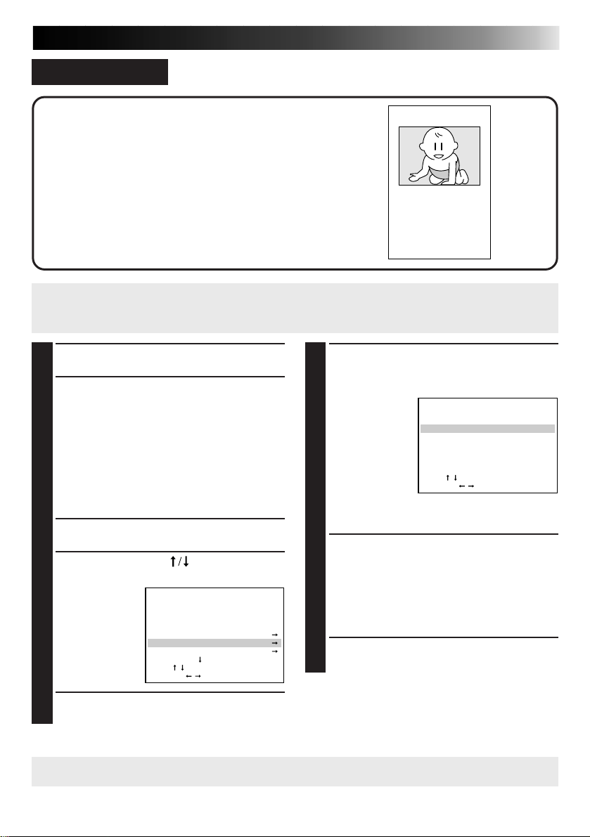
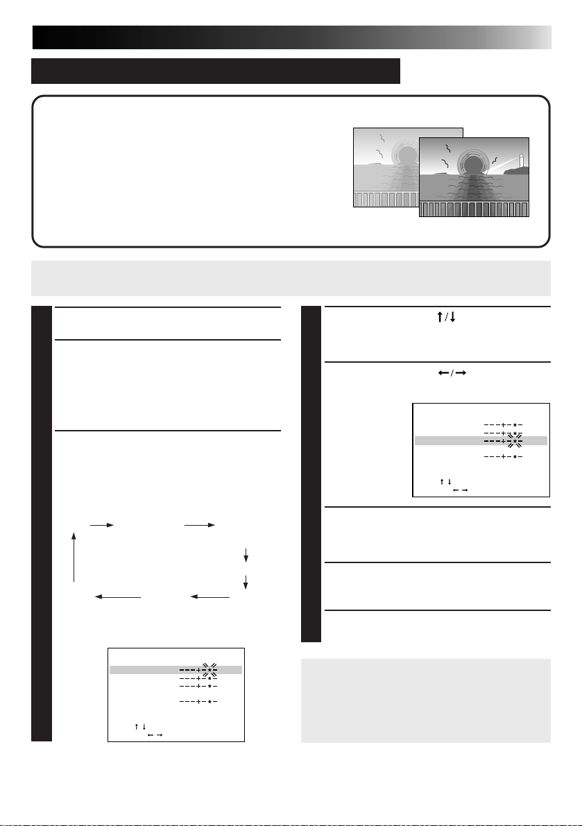
TRIMMING PRINT
You can cut out a particular part of an image and
enlarge it for printing. The size of the part to be
trimmed can be selected.
Preparation
● See page 12.
● Press INPUT SELECT to select the appropriate input
mode depending on the connection to the source unit
(Z page 18).
•If IrDA (INFRARED) or PC MODE is selected, you do
not have to perform steps 1 and 2. Refer to page 20 or
38 to send the image you want to print to the printer.
BEGIN SOURCE PLAYBACK
1
1
PRESS MEMORY WHEN THE
2
DESIRED IMAGE APPEARS
•If the image is unstable, press MEMORY
again.
2
PRESS OK
PRESS MENU
3
PRESS CURSOR TO SELECT EFFECT,
4
THEN PRESS OK
PRESS CURSOR TO SELECT
5
TRIMMING ON EFFECT SET MENU,
THEN PRESS OK
Page 29
29
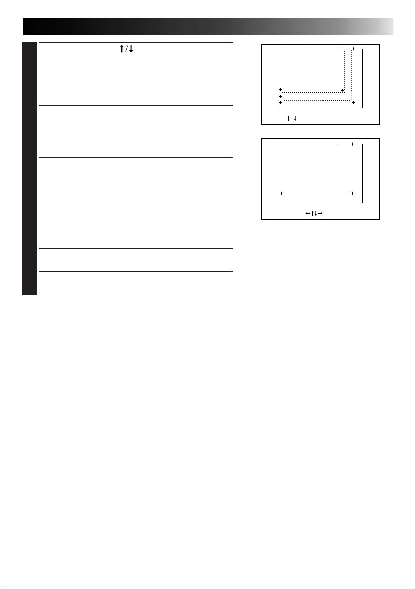
PRESS CURSOR TO SELECT THE
6
SIZE OF THE PART TO BE TRIMMED,
THEN PRESS OK
•To go back to the EFFECT SET MENU, press
MENU before pressing OK.
PRESS CURSOR TO SELECT THE
7
POSITION OF THE PART TO BE
TRIMMED
•To go back to the SIZE set screen, press MENU.
PRESS OK
8
•The processed image will be displayed.
•Since the size and position of the part to be
trimmed are approximate, the actual trimmed
image may not exactly match what was specified.
•If you want to cancel and try again, press
MENU.
PRESS OK
9
PRESS PRINT TO START
10
PRINTING
SIZE
[
SIZE
/ ] QUIT [MENU] OK [OK]
POSITION
SELECT
[
]
OK [OK]
Page 30

30
MENU 2 2/2
EFFECT
TITLE
FRAME
QUALITY :
.STD HIGH
PICTURE MEMORY
TO MENU 1
[ ]
ITEM
[
/
]
OK [OK]
SELECT
[
/
]
QUIT [MENU]
EFFECT SET MENU
ROTATION : R90&
:
L90&
:
180&
MIRROR
TRIMMING
ITEM
[
/
]
OK [OK]
QUIT [MENU]
DIFFERENT TYPES OF PRINTING (cont.)
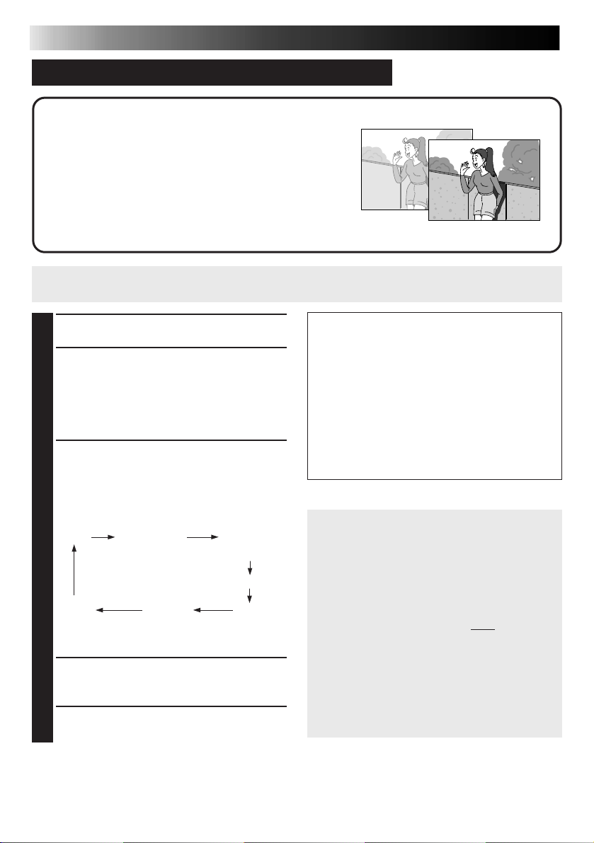
ROTATING/REVERSING IMAGES
You can rotate an image 90& clockwise/counterclockwise or
180°, or you can reverse it to create a mirror image. If you
rotate a horizontal image 90&, it will be automatically
resized to fit the vertical layout.
Preparation
● See page 12.
● Press INPUT SELECT to select the appropriate input mode
depending on the connection to the source unit (Z page 18).
•If IrDA (INFRARED) or PC MODE is selected, you do
not have to perform steps 1 and 2. Refer to page 20 or
38 to send the image you want to print to the printer.
BEGIN SOURCE PLAYBACK
1
1
PRESS MEMORY WHEN THE
2
DESIRED IMAGE APPEARS
•If the image is unstable, press MEMORY
again.
2
PRESS OK
PRESS MENU
3
PRESS CURSOR TO SELECT
4
EFFECT, THEN PRESS OK
PRESS CURSOR TO SELECT THE
5
DESIRED ITEM ON EFFECT SET MENU
PRESS OK
6
•The image will be processed as selected.
•If R90° or L90° is selected, there will be a thin
blank portion at the right and left of the image.
•If you want to cancel and try again, press MENU.
PRESS OK
7
PRESS PRINT TO START PRINTING
8
Page 31

31
SEL [ / ]
OK [OK]
QUIT
[MENU]
TITLE IMPOSE
Seven different titles including Congratulations! are
stored in the printer and can be called up for
superimposed printing. Colors and positions of the
titles are set in advance.
Preparation
● See page 12.
● Press INPUT SELECT to select the appropriate input mode
depending on the connection to the source unit (Z page 18).
•If IrDA (INFRARED) or PC MODE is selected, you do not have to perform steps 1 and 2. Refer to page
20 or 38 to send the image you want to print to the printer.
BEGIN SOURCE PLAYBACK
1
1
PRESS MEMORY WHEN THE
2
DESIRED IMAGE APPEARS
•If the image is unstable, press
MEMORY again.
2
PRESS OK
PRESS MENU
3
PRESS CURSOR TO SELECT
4
TITLE, THEN
PRESS OK
● If you want to print a different image…
Follow the instructions below to erase the title before printing.
1 Perform steps
of the screen in step
EFFECT
TITLE
FRAME
QUALITY :
PICTURE MEMORY
TO MENU 1
ITEM
SELECT
3
– 6 described above, selecting the blank frame in the upper left corner
MENU 2 2/2
.STD HIGH
[ ]
[
]
/
[
/ ]QUIT [MENU]
5
.
OK [OK]
PRESS CURSOR TO SELECT
5
THE
DESIRED
TITLE
PRESS OK
6
•The image appears on screen with the
selected title superimposed on it.
•If you want to cancel and try again,
press MENU.
PRESS OK
7
PRESS PRINT TO START
8
PRINTING
2 Press SOURCE/STORED IMAGE to switch back to the input display.
The title is now erased.
● You can use frame impose (
imposing first, then title imposing.
Z page 32) and title impose at the same time. Perform frame
Page 32
32
SEL [ / ]
OK [OK]
QUIT
[MENU]
DIFFERENT TYPES OF PRINTING (cont.)
FRAME IMPOSE
Seven different frames are stored in the printer and can
be called up for superimposed printing.
Preparation
● See page 12.
● Press INPUT SELECT to select the appropriate input mode
depending on the connection to the source unit (Z page 18).
•If IrDA (INFRARED) or PC MODE is selected, you do not have to perform steps 1 and 2. Refer to page
20 or 38 to send the image you want to print to the printer.
BEGIN SOURCE PLAYBACK
1
1
PRESS MEMORY WHEN THE
2
DESIRED IMAGE APPEARS
•If the image is unstable, press
MEMORY again.
2
PRESS OK
PRESS MENU
3
PRESS CURSOR TO SELECT
4
FRAME,
THEN
PRESS OK
● If you want to print a different image…
Follow the instructions below to erase the frame before printing.
1 Perform steps
of the screen in step
2 Press SOURCE/STORED IMAGE to switch back to the input display.
The frame is now erased.
EFFECT
TITLE
FRAME
QUALITY :
PICTURE MEMORY
TO MENU 1
ITEM
SELECT [ / ] QUIT [MENU]
3
– 6 described above, selecting the blank frame in the upper left corner
MENU 2 2/2
[ ]
[
]
/
5
.
.STD HIGH
OK [OK]
PRESS CURSOR TO SELECT
5
THE
DESIRED
FRAME
PRESS OK
6
•The image appears on screen with the
selected frame superimposed on it.
•If you want to cancel and try again,
press MENU.
PRESS OK
7
•If you also want to superimpose one of
the stored titles on the image, perform
3
– 7 on page 31.
steps
PRESS PRINT TO START
8
PRINTING
Page 33
CONVENIENT FUNCTIONS
SEL [ / ]
OK [OK]
QUIT
[MENU]
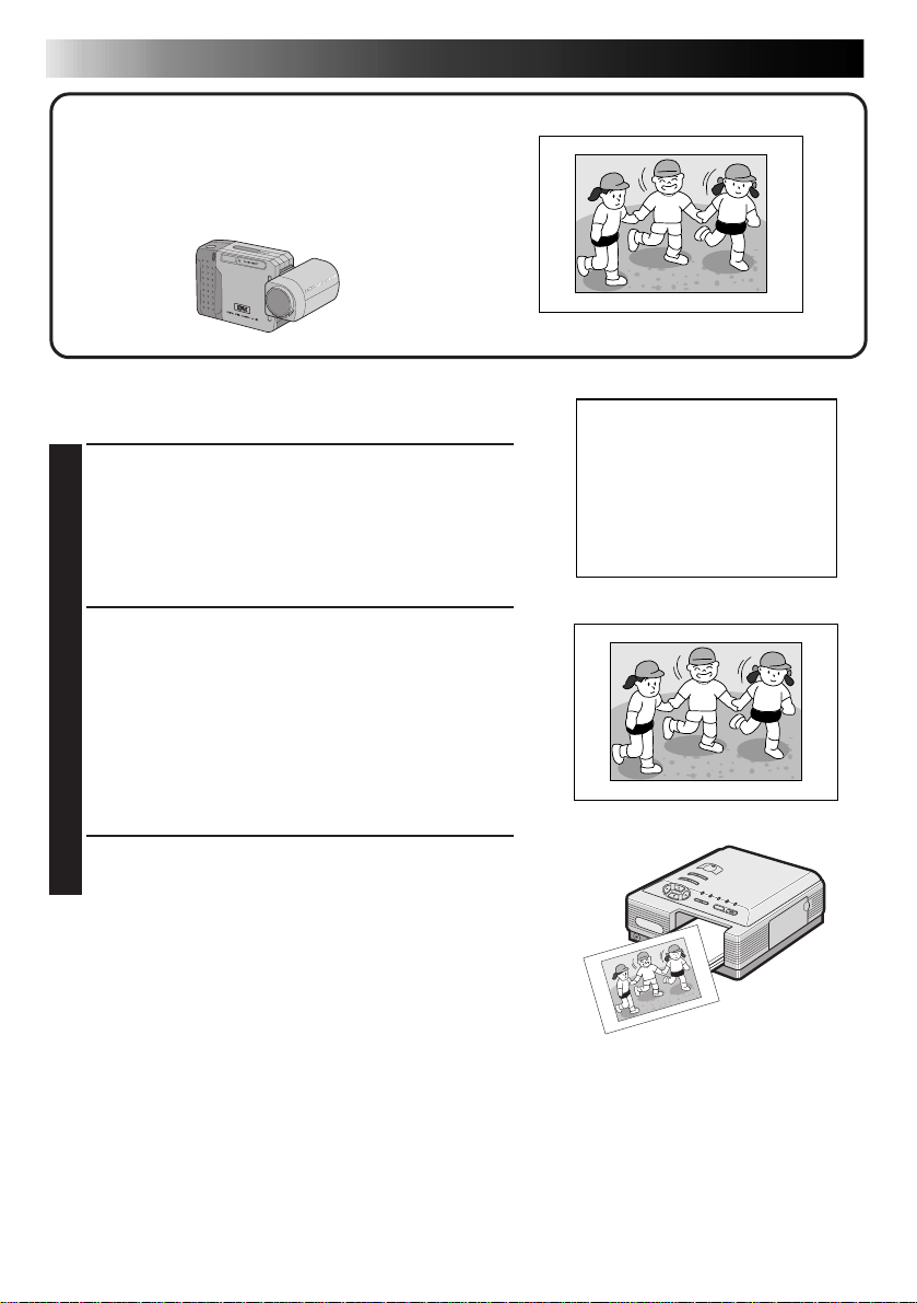
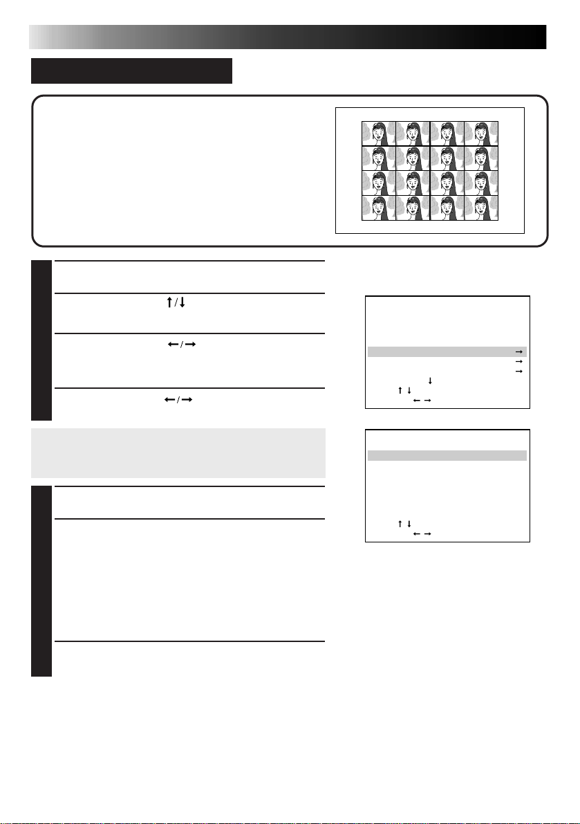
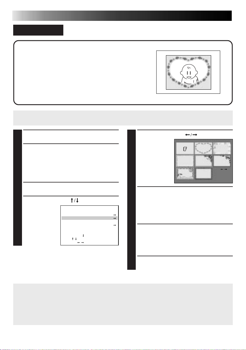
EXACT FRAME FUNCTION
33
The printer stores 54 frames when the MEMORY
button is pressed, letting you choose the best image
even if you didn’t press the button at the right
moment.
Preparation
● See page 12.
● Press INPUT SELECT to select the DV or VIDEO mode.
(Z page 18)
BEGIN SOURCE PLAYBACK
1
PRESS EXACT FRAME
2
•The EXACT FRAME lamp lights up.
•If there is no video input, NO INPUT IMAGE
appears on the screen. Make sure all the relevant
appliances are connected correctly and the
appropriate input mode is selected, then try again.
PRESS MEMORY WHEN THE DESIRED
3
IMAGE APPEARS
•Consecutive images are stored in sequence in
memory.
PRESS CURSOR TO SELECT THE
4
IMAGE
•Place the Z mark on the image you want to
print.
•If you want to exit the EXACT FRAME screen,
press MENU.
MEMORY
PRESS OK
5
•The selected image appears on screen.
•If you want to select a different image, press
MENU and perform steps
•If the image is unstable, press MEMORY again.
PRESS OK
4
and 5 again.
6
PRESS PRINT TO START PRINTING
7
Page 34
34
CONVENIENT FUNCTIONS (cont.)
PICTURE PROCESSOR FUNCTION (Auto Adjustment)
You can add one of the following special effects to an
image: Auto Picture Adjustment, Clear Black, Back-Lit
Compensation, B/W, Sepia. The image will be
automatically processed by the printer.
Preparation
● See page 12.
● Press INPUT SELECT to select the appropriate input mode
depending on the connection to the source unit (Z page 18).
•If IrDA (INFRARED) or PC MODE is selected, you do not have to perform steps 1 and 2. Refer to page
20 or 38 to send the image you want to print to the printer.
BEGIN SOURCE PLAYBACK
1
1
PRESS MEMORY WHEN THE
2
DESIRED IMAGE APPEARS
•If the image is unstable, press
MEMORY again.
2
PRESS OK
PRESS PICTURE PROCESSOR
3
UNTIL THE DESIRED ITEM
SETTING SCREEN APPEARS
•Pressing the PICTURE PROCESSOR
button changes the mode as follows:
AUTO
original
image
•If you want to restore the original image
during adjustment, simply press MENU.
PURE BLACK
(clear black)
MONOTONE (black & white)
MANUAL
PRESS OK
4
•The processed image appears on screen.
PRESS PRINT TO START
5
PRINTING
TWILIGHT
(back-lit
compensation)
SEPIA
What Each Mode Does
AUTO The printer automatically adjusts
PURE BLACK Gives images better contrast by
TWILIGHT Lights up dark objects or faces
MONOTONE Black & white.
SEPIA Brownish tint like old photos.
MANUAL You can manually adjust the tint/
● If you press PICTURE PROCESSOR when
no image is stored in the printer, NO
STORED IMAGE appears on the screen.
Store an image in the printer first, then
press PICTURE PROCESSOR again.
● If you want to use title/frame impose
when the AUTO mode is selected, be
sure to add the title/frame
performing Picture Processor adjustment;
otherwise, it will cause picture quality
deterioration.
● When the AUTO mode is selected, some
images may not be adjusted as desired. If
this is the case, try MANUAL adjustment.
(
Z p. 35)
the tint/brightness/contrast to the
optimum level.
enhancing the black color.
with brighter and clearer colors.
brightness/contrast.
after
Page 35
35
MANUAL
TINT CYAN RED
YELLOW BLUE
CONTRAST LOW HIGH
BRIGHTNESS
LOW HIGH
QUIT [PICTURE PROCESSOR]
ITEM
[
/
]
OK [OK]
ADJUST
[
/
]
PICTURE PROCESSOR FUNCTION (Manual Adjustment)
You can perform manual picture processing on an
image. There are 7 levels for each of the following
items: TINT (CYAN/RED, YELLOW/BLUE),
CONTRAST (LOW/HIGH) and BRIGHTNESS (LOW/
HIGH).
Preparation
● See page 12.
● Press INPUT SELECT to select the appropriate input mode
depending on the connection to the source unit (Z page 18).
•If IrDA (INFRARED) or PC MODE is selected, you do not have to perform steps 1 and 2. Refer to page
20 or 38 to send the image you want to print to the printer.
BEGIN SOURCE PLAYBACK
1
1
PRESS MEMORY WHEN THE
2
DESIRED IMAGE APPEARS
•If the image is unstable, press
MEMORY again.
2
PRESS OK
PRESS PICTURE PROCESSOR
3
UNTIL THE MANUAL SCREEN
APPEARS
•Pressing the PICTURE PROCESSOR
button changes the mode as follows:
AUTO
original
image
•If you want to restore the original image
during adjustment, simply press MENU.
PURE BLACK
(clear black)
TINT CYAN RED
YELLOW BLUE
CONTRAST LOW HIGH
BRIGHTNESS
LOW HIGH
QUIT [PICTURE PROCESSOR]
ITEM
ADJUST
MONOTONE (black & white)
MANUAL
[
]
/
[
]
/
OK [OK]
TWILIGHT
(back-lit
compensation)
SEPIAMANUAL
PRESS CURSOR TO SELECT
4
THE ITEM YOU WANT TO
ADJUST
PRESS CURSOR TO
5
ADJUST
•If you want
to exit the
MANUAL
screen, press
PICTURE
PROCESSOR.
REPEAT STEPS 4 AND 5 UNTIL
6
THE IMAGE APPEARS AS
DESIRED
PRESS OK
7
•The processed image appears on screen.
PRESS PRINT TO START
8
PRINTING
● If you press PICTURE PROCESSOR when
no image is stored in the printer, NO
STORED IMAGE appears on screen.
Store an image in the printer first, then
press PICTURE PROCESSOR again.
Page 36
36
MENU 2 2/2
EFFECT
TITLE
FRAME
QUALITY :
.STD HIGH
PICTURE MEMORY
TO MENU 1
[ ]
ITEM
[
/
]
OK [OK]
SELECT [ / ] QUIT [MENU]
PICTURE MEMORY
PICTURE 1 PICTURE 2
PICTURE 3 PICTURE 4
PICTURE 5 PICTURE 6
PICTURE 7 PICTURE 8
PLEASE SELECT
MEMORY NUMBER
OK [OK]
SELECT [ / ] QUIT [MENU]
CONVENIENT FUNCTIONS (cont.)
PICTURE MEMORY FUNCTION — To Store An Image In Memory
You can store up to 8 of your favorite images in the
printer’s memory. Even if you turn the power off,
these images will remain in memory.
Preparation
● See page 12.
● Press INPUT SELECT to select the appropriate input
mode depending on the connection to the source unit
(Z page 18).
•If IrDA (INFRARED) or PC MODE is selected, you do
not have to perform steps 1 and 2. Refer to page 20 or
38 to send the image you want to print to the printer.
BEGIN SOURCE PLAYBACK
1
1
PRESS MEMORY WHEN THE
2
DESIRED IMAGE APPEARS
•If the image is unstable, press MEMORY
again.
2
PRESS OK
PRESS MENU
3
PRESS CURSOR TO SELECT
4
PICTURE MEMORY, THEN PRESS OK
PRESS CURSOR TO SELECT THE
5
IMAGE YOU WANT TO REPLACE
•The selected image will be replaced with the
new one.
•If you press MENU before pressing OK, you will
exit the PICTURE MEMORY screen.
NOTE: The replaced image cannot be restored
once you press OK.
Page 37

PICTURE MEMORY FUNCTION — To View Stored Images
PICTURE MEMORY
PICTURE 1 PICTURE 2
PICTURE 3 PICTURE 4
PICTURE 5 PICTURE 6
PICTURE 7 PICTURE 8
PLEASE SELECT A PICTURE
QUIT [INPUT SELECT] OK [OK]
You can call up stored images for viewing or printing.
PRESS INPUT SELECT SO THAT THE
1
PICTURE MEMORY SCREEN APPEARS
PRESS CURSOR TO SELECT THE
2
IMAGE YOU WANT TO VIEW
PRESS OK
3
•The image you want to view appears on the
screen.
•If you want to print the image, press PRINT.
When You Store Images In Picture Memory...
● If you want to store more than one image in memory, repeat steps 1 – 5 of To Store An
Image In Memory described on page 36.
● If HIGH is selected on QUALITY, you can store images in PICTURE 1 and 2 only.
● If STD is selected on QUALITY, you can store images in PICTURE 1 through 8.
37
Page 38

38
CONVENIENT FUNCTIONS (cont.)
HOW TO MAKE CONNECTIONS WITH A COMPUTER
By connecting the printer to your computer and using the provided image transfer software, you
can manipulate images more easily and process/print them with higher picture quality.
Preparation
● Install the provided image transfer software in your computer.
● Connect the printer to the computer.
To video input connector
To RS-232C connector
Macintosh
To the modem or
printer port
PRESS INPUT SELECT TO SELECT
1
PC MODE
•The PC lamp lights up.
•If you select PC MODE when a source
unit is connected to the printer’s VIDEO
INPUT connector, the picture input from
the VIDEO INPUT connector appears
on the screen.
TRANSMIT VIDEO DATA IN THE
2
COMPUTER TO THE PRINTER
•For details, refer to the instruction
manual of the provided image transfer
software.
•While video data are being transmitted:
the PC lamp blinks.
•While video data are being converted:
the PRINT lamp blinks.
(Set the input select switch
to VIDEO)
WindowsW PC connection
cable (D-sub 9-pin for
PC/AT-compatibility)
To PC connector
W
connection cable
To PC connector
WHEN THE PRINT LAMP STAYS
3
LIT, PRESS PRINT TO START
PRINTING
● You can also save images on the
computer that are stored in the printer
and ready for printing by clicking on the
Save All button in the Album window of
the provided image transfer software.
● It is recommended to transmit video data
to the computer
transmit video data to the computer after
you finish printing, the picture quality
may be changed.
Printer
TV
Rear panel
connectors
VIDEO OUT
PC
before printing; if you
To video output
connector
Page 39
TROUBLESHOOTING
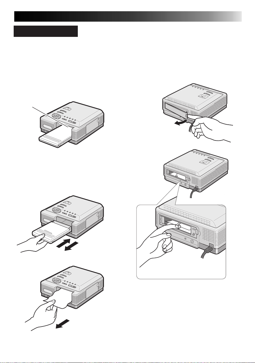
WHEN PAPER JAMS
1
.
Press POWER to turn off the printer
power first, and unplug the power cord.
•Stored images will be erased unless they
are stored using the Picture Memory
function.
2
.
Remove the jammed sheet from the slot
of the paper tray.
Slot
If the jammed paper cannot be
removed in step 2
3
.
Remove the paper tray then remove the
jammed sheet.
39
If the jammed paper cannot be
removed in step 3
4
.
Remove the jammed paper removing
door and remove the paper.
Lift the white lever and
remove the jammed paper.
After removing the paper
5
.
Insert the paper tray and replace the
jammed paper removing door.
6
.
Plug in the power cord and turn on the
power.
Page 40
40
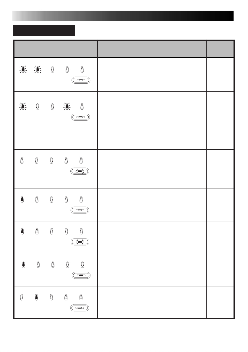
LAMP INDICATIONS
TROUBLESHOOTING (cont.)
Lamp indication
DV IrDA (IrTran-P) VIDEO PC EXACT FRAME
Blinking
quickly
DV IrDA (IrTran-P) VIDEO PC EXACT FRAME
Blinking
quickly
DV IrDA (IrTran-P) VIDEO PC EXACT FRAME
DV IrDA (IrTran-P) VIDEO PC EXACT FRAME
Lit
Blinking
quickly
PRINT
PRINT
PRINT
Blinking quickly
PRINT
v Appears when:
m Recommended actions:
v Ink running out or ink cassette not
loaded.
m Replace with new one or insert ink
cassette.
One of the following occurs:
1) v Rear door is open.
m Close the rear door.
2) v Paper tray not loaded.
m Fill the tray with print sheets and load it.
3) v Print paper running out or jammed.
m Refill print sheets or remove the
jammed sheet.
v Temperature within the printer is high.
The PRINT lamp may also blink quickly
during printing.
m Wait until the PRINT lamp stops
blinking.
v DV mode selected, with no picture
stored in memory.
Reference
pages
14
15
39
—
16
DV IrDA (IrTran-P) VIDEO PC EXACT FRAME
Lit
DV IrDA (IrTran-P) VIDEO PC EXACT FRAME
Lit
DV IrDA (IrTran-P) VIDEO PC EXACT FRAME
Lit
PRINT
Blinking
PRINT
Lit
PRINT
v DV data being converted.
v DV data converted.
m Pressing the PRINT button prints the
stored picture.
v IrDA (INFRARED) mode selected, with
no picture stored in memory.
16
16
17
Page 41
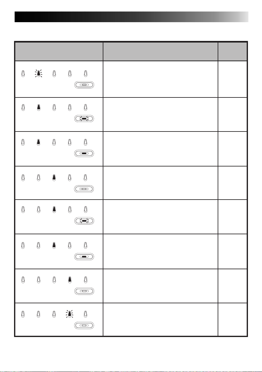
41
Lamp indication
DV IrDA (IrTran-P) VIDEO PC EXACT FRAME
Blinking
DV IrDA (IrTran-P) VIDEO PC EXACT FRAME
Lit
DV IrDA (IrTran-P) VIDEO PC EXACT FRAME
Lit
DV IrDA (IrTran-P) VIDEO PC EXACT FRAME
Lit
DV IrDA (IrTran-P) VIDEO PC EXACT FRAME
Lit
DV IrDA (IrTran-P) VIDEO PC EXACT FRAME
Lit
PRINT
PRINT
Blinking quickly
PRINT
Lit
PRINT
PRINT
Blinking quickly
PRINT
v Appears when:
m Recommended actions:
v IrDA (IrTran-P) data being received.
v IrDA (IrTran-P) data being converted.
v IrDA (IrTran-P) reception finished.
m Pressing the PRINT button prints the
stored picture.
v VIDEO mode is selected, with no
picture stored in memory.
v Video data being converted.
v Video data converted.
m Pressing the PRINT button prints the
stored picture.
Reference
pages
17
17
17
16
16
16
Lit
DV IrDA (IrTran-P) VIDEO PC EXACT FRAME
PRINT
Lit
DV IrDA (IrTran-P) VIDEO PC EXACT FRAME
Blinking
PRINT
v Ready to receive picture data from the
PC.
38
v Picture data being received from the
PC.
38
Page 42

42
TROUBLESHOOTING (cont.)
Lamp indication
DV IrDA (IrTran-P) VIDEO PC EXACT FRAME
Blinking
DV IrDA (IrTran-P) VIDEO PC EXACT FRAME
DV IrDA (IrTran-P) VIDEO PC EXACT FRAME
DV IrDA (IrTran-P) VIDEO PC EXACT FRAME
DV IrDA (IrTran-P) VIDEO PC EXACT FRAME
DV IrDA (IrTran-P) VIDEO PC EXACT FRAME
PRINT
Lit
PRINT
Lit
Lit
Lit
PRINT
PRINT
PRINT
Blinking quickly
PRINT
Lit
v Appears when:
m Recommended actions:
v Picture data being captured from the
printer to the PC.
v Picture data communication with the
PC has finished.
v Exact Frame is ready. Pressing the
MEMORY button stores 54 frames
(total: 8 images) in memory.
v If the power is on, Picture Memory is
selected.
v Video data in Picture Memory being
converted.
v Video data in Picture Memory
converted.
m Pressing the PRINT button prints the
stored picture.
Reference
pages
38
38
33
37
37
37
Page 43
43
OTHER PROBLEMS
This unit is a precision machine which includes a microprocessor. Its operational performance
may be influenced by external noise or disturbance. If normal operation cannot be achieved
even after taking appropriate actions as defined below, the power should be turned off by
unplugging the power cable. Then, reconnect the power by plugging it in again and recheck for
proper operation.
Power won’t turn on
Lamp lights
(or blinks)
Paper is jammed
Ink cassette is empty
Two or more
stacked sheets have
printed
The stored image
has disappeared
Color is weak or
wrong
The image you want
to print from the
playback unit
cannot be called up
on screen
Check to see ifIf
v The power cord is unplugged.
v Take the appropriate action according to LAMP
INDICATIONS on pages 40 – 42. If such an action
fails to solve the problem, turn the power off,
unplug the power cable and wait for a few
minutes. Then, plug the cable in and turn the
power on again.
v The paper jam may be due to the printer being set
upright or tilted.
v Remove paper as directed on page 39.
v Remove the paper tray and check for jammed
paper. If paper is jammed, place the jammed paper
in the tray and load it in the printer.
v Color print paper sheets have been properly
shuffled. If not, shuffle them thoroughly to separate
each sheet before placing them on the paper tray.
v The stored picture is erased when you turn the
printer power off or switch between IrDA (IrTran-P)
and DV modes. Carry out the storage procedure
again.
v Colors are generally acceptable. The colors on the
TV screen may be somewhat different from those
actually printed, which is normal with this Printer.
v Use the Picture Processor function for picture
adjusment.
v Printing results may not be normal if you play back
a tape recorded with another camcorder, or if you
store an image on a section of tape that contains
scratches or noise. Try storing it on a different
section.
Reference
pages
—
40
|
42
39
15
15
—
34
35
—
Page 44

44
TROUBLESHOOTING (cont.)
If
Picture data cannot
be transmitted
through the DV
connection
Picture blurred
when printed from a
camcorder via the
DV connector
Picture data cannot
be transmitted using
IrDA (IrTran-P)
communication
Picture does not
appear on the TV
screen when the DV
connection is used
The printer’s status
indication is not
displayed on the TV
screen
The stored image
looks overly bright
on the screen.
Check to see if
v The printer is in the DV mode.
m Press the INPUT SELECT button to light the DV lamp.
v The cable is connected correctly.
m Check for proper connections.
v An image is recorded on the DV tape.
m Use a tape with picture data recorded on it.
v The camcorder is in the Still Picture mode.
m When transferring a picture from the camcorder to
the printer using the DV connector, set the
camcorder to the Still Picture mode.
m After transferring the picture to the printer, press
the MEMORY button again to stabilize it.
v The printer is in IrDA (INFRARED) mode.
m Press the INPUT SELECT button to light the IrDA
(IrTran-P) lamp.
v Picture data is being transmitted at the correct
distance and angle.
m Aim the transmitter at the printer’s IrDA (IrTran-P)
sensor. Keep the transmitter within a distance of
approximately 19”. Data communications may be
difficult at too close or too remote a distance
depending on the machines in use.
v The TV is connected properly to the printer using a
video cable.
m Connect the TV to the printer using a video cable
to monitor the image on the screen.
v The MENU screen is displayed.
m Press MENU to exit the MENU screen.
v Depending on the stored image, it may look overly
bright on the TV screen. However, this will not
affect the actual prints.
Reference
pages
16
18
18
17
20
16
10
—
Page 45

WHAT TO DO IF ANY OF THE MESSAGES BELOW APPEAR
45
Message
PULL OUT PAPER
TRAY AND CHECK
PAPER.
CLOSE BACK
DOOR.
NOW PRINTING!!
PLEASE WAIT.
SET INK CASSETTE
AND CLOSE COVER.
SET PAPER TRAY.
REPLACE INK
CASSETTE.
PAPER JAMMED.
REMOVE PAPER.
PRINT ERROR HAS
OCCURRED.
v Appears when:
m Action:
v The paper tray is running out of paper or the paper
feed is not working properly.
m Remove the paper tray and correctly set the print
sheets.
v The jammed paper removing door is open.
m Close the jammed paper removing door.
v Printing is in progress.
v The picture is being processed, or the internal
temperature in the printer is too high.
m Wait until the message disappears.
v The ink cassette is not set or is improperly set.
m Insert the ink cassette until it clicks and close the
cover.
v The paper tray is not inserted correctly.
m Place color print paper sheets on the paper tray
and insert it correctly.
v The ink cassette is used up.
m Replace it with a new one.
m If the paper tray is running out of paper, remove it
and check if paper is jammed; if so, put the
jammed paper in the paper tray and insert it back
into the printer.
v Paper is jammed during printing.
m Remove paper (refer to page 39).
v Printing was not done properly.
m Turn off the power and unplug the power cord,
then plug it back into the AC outlet and try again.
m If paper is jammed, refer to page 39 to remove it.
Page
15
10
—
—
14
15
14
15
39
39
Page 46
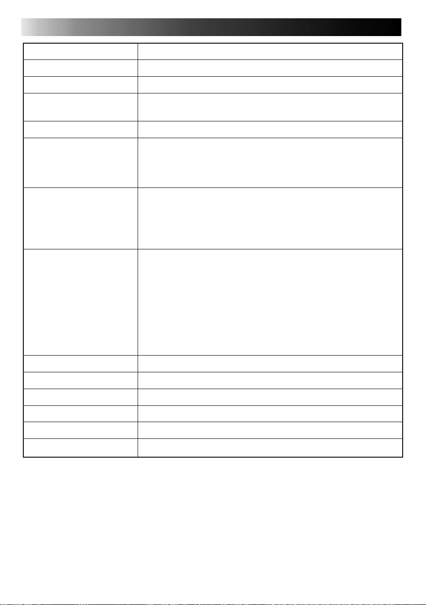
46
SPECIFICATIONS
Power
Power consumption
Print format
Print quality
Resolution
Print medium
Print speed
(QUALITY STD/HIGH)
* Transmission and
processing of video data
is not included.
Connectors
Operating temperature
Operating humidity
Storage temperature
Operating position
Dimensions
Weight
AC 120 V `, 60 Hz
During printing : Approx. 73 W, 0.85 A
Sublimation dye thermal transfer line printing
Resolution : 1360 (horiz.) x 1024 (vert.) dots
Gradation : 256 tones
306 dpi
Ink sheet : Cartridge
(dedicated)
Print sheet : Paper size 144 x 100 mm
(dedicated) Maximum print area 112 x 84 mm
Standard/Sticker Print Paper (65/125 sec.)
Super-Fine High Grade paper (85/160 sec.)
DV input : DV connector
Normal video input : VIDEO INPUT connector
S-Video input : S INPUT connector
IrDA (IrTran-P) input : IrDA (IrTran-P) sensor
Serial : PC connector (ø 2.5 mm)
Normal video output : VIDEO OUT connector
+5 — +35°C (+41 — +95°F)
35 — 80%
–20 — +60°C (–4 — +140°F)
Level (horizontal) ±5°
213 W x 107 H x 213 D mm (8-7/16” x 4-1/4” x 8-7/16”)
Approx. 2.3 kg (5.1 lbs)
3-color consecutive printing (yellow, magenta, cyan)
(Conforms to the IrDA (IrTran-P)
standard and compatible with
IrDA (IrTran-P) Ver 1.0)
Design and specifications subject to change without notice.
Page 47

INDEX
A
Automatic Picture Adjustment ......... Z pg. 34
B
Back-Lit Compensation ................... Z pg. 34
Black & White.................................
C
Calendar Print ................................. Z pg. 27
Cable Connections ....................
Clear Black .....................................
Color Print Paper Sheet Set..............
Cursor Buttons ................................
D
DV IN Connector ............................ Z pg. 16
DV Lamp ........................................
E
Error Messages ................................ Z pg. 45
EXACT FRAME Button .....................
Exact Frame Function ......................
EXACT FRAME Lamp ......................
F
Frame Impose ................................. Z pg. 32
Frame Stabilizer ...............................
H
HIGH (High Picture Quality)
Mode ..............................................
How To Make Connections...
I
Ink Cassette ..................................... Z pg. 14
Ink Cassette Door ............................
INPUT SELECT Button .....................
IrDA (IrTran-P) Infrared sensor ...
IrDA (IrTran-P) Infrared Video Data
Communications .......................
IrDA (IrTran-P) Lamp .................
IrDA (IrTran-P) Reception ..........
J
Jammed Paper Removing Door ....... Z pg. 39
L
Lamp Indications............................. Z pg. 40
Layout .............................................
Z pg. 34
Z pg. 16, 18
Z pg. 34
Z pg. 13
Z pg. 22
Z pg. 10
Z pg. 33
Z pg. 33
Z pg. 33
Z pg. 11
Z pg. 23
Z pg. 16, 17, 38
Z pg. 14
Z pg. 18
Z pg. 17, 20
Z pg. 17, 20
Z pg. 17, 20
Z pg. 17, 20
Z pg. 22
47
M
MEMORY Button.............................. Z pg. 11
Multi-Print (Different Scenes) ..........
Multi-Print (Same Scene) .................
N
Number of Prints ............................. Z pg. 23
O
OK Button ....................................... Z pg. 10
ON SCREEN....................................
P
Paper Tray ....................................... Z pg. 15
Paper Tray Insertion Door................
PC Connector..................................
PC Lamp .........................................
Picture Adjustment ....................
Picture Memory Function ................
PICTURE PROCESSOR Button...
Picture Processor Function ........
PRINT Button ..................................
Print Speed......................................
Provided Accessories ........................
R
Reversing Images ............................ Z pg. 30
Rotating Images...............................
S
Sepia ............................................... Z pg. 34
SOURCE/STORED IMAGE Button ...
STD (Standard) Mode ......................
Strobe Print .....................................
S-Video INPUT Connector ..............
T
Title Impose .................................... Z pg. 31
Trimming.........................................
V
VIDEO INPUT Connector ............... Z pg. 16
VIDEO Lamp...................................
VIDEO OUTPUT Connector ...........
W
When Paper Jams ............................ Z pg. 39
Z pg. 25
Z pg. 24
Z pg. 23
Z pg. 10
Z pg. 38
Z pg. 38
Z pg. 34, 35
Z pg. 36
Z pg. 34, 35
Z pg. 34, 35
Z pg. 11
Z pg. 23
Z pg. 9
Z pg. 30
Z pg. 11
Z pg. 23
Z pg. 26
Z pg. 16
Z pg. 28
Z pg. 10
Z pg. 16
Page 48

48
FOR SERVICING (Only in U.S.A.)
HOW TO LOCATE YOUR JVC SERVICE CENTER
TOLL FREE: 1-800-252-5722
Dear customer:
In order to receive the most satisfaction from your purchase, read the instruction booklet before
operating the unit. In the event that repair is necessary, or for the address nearest your location,
please refer to the factory service center list below or within the Continental United States, call 1-800252-5722 for your authorized servicer. Remember to retain your Bill of Sale for Warranty Service.
— JVC
JVC SERVICE & ENGINEERING
COMPANY OF AMERICA
DIVISION OF US JVC CORP.
FACTORY SERVICE CENTER LOCATIONS
107 Little Falls Road 1500 Lakes Parkway 705 Enterprise Street
Fairfield, NJ 07004-2105 Lawrenceville, GA 30243-5857 Aurora, IL 60504-8135
(973) 808-9279 (770) 339-2522 (630) 851-7855
5665 Corporate Avenue 10700 Hammerly Blvd., Suite 110 2969 Mapunapuna Place, Suite 101
Cypress, CA 90630-4727 Houston, TX 77043-2310 Honolulu, HI 96819-2000
(714) 229-8011 (713) 935-9331 (808) 833-5828
13 Cummings Park 8192 West State Road 84 890 Dubuque Avenue
Woburn, MA 01801-2105 Davie, FL 33324-4611 South San Francisco, CA 94080-1804
(781) 376-9100 (954) 472-1960 (415) 871-2666
Sophisticated electronic products may require occasional service. Just as quality is a keyword in the
engineering and production of the wide array of JVC products, service is the key to maintaining the
high level performance for which JVC is world famous. The JVC service and engineering organization
stands behind our products.
NATIONAL HEADQUARTERS
JVC SERVICE & ENGINEERING COMPANY OF AMERICA
DIVISION OF JVC AMERICAS CORP.
1700 Valley Road
Wayne, NJ 07470-8498
If you ship the product...
Pack your JVC unit in the original carton or one of equivalent size and strength. Enclose, with the unit,
a letter stating the problem or symptom that exists and also a copy of the receipt or bill of sale you
received when you purchased your JVC unit. Print your home return address on the outside and the
inside of the carton. Send to the appropriate JVC Factory Service Center as listed above.
ACCESSORIES
To purchase accessories for your JVC product, you
may contact your local JVC Dealer.
Or from the 48 Continental United States call toll free:
1-800-882-2345.
Don’t service it yourself.
CAUTION
To prevent electrical shock, do not open the
cabinet. No user serviceable parts inside.
Refer servicing to qualified service personnel.
Page 49

WARRANTY (Only in U.S.A.)
49
LIMITED WARRANTY
JVC COMPANY OF AMERICA warrants this product and all parts thereof, except as set forth below ONLY TO
THE ORIGINAL PURCHASER AT RETAIL to be FREE FROM DEFECTIVE MATERIALS AND WORKMANSHIP
from the date of original retail purchase for the period as shown below. (“The Warranty Period”)
PARTS
THIS LIMITED WARRANTY IS VALID ONLY IN THE FIFTY (50) UNITED STATES, THE DISTRICT OF
COLUMBIA AND IN COMMONWEALTH OF PUERTO RICO.
WHAT WE WILL DO:
If this product is found to be defective, JVC will repair or replace defective parts at no charge to the original owner.
Such repair and replacement services shall be rendered by JVC during normal business hours at JVC authorized
service centers. Parts used for replacement are warranted only for the remainder of the Warranty Period. All
products and parts thereof may be brought to a JVC authorized service center on a carry-in basis except for
Television sets having a screen size 25 inches and above which are covered on an in-home basis.
WHAT YOU MUST DO FOR WARRANTY SERVICE:
Return your product to a JVC authorized service center with a copy of your bill of sale. For your nearest JVC
authorized service center, please call toll free: (800) 252-5722.
If service is not available locally, box the product carefully, preferably in the original carton, and ship, insured, with
a copy of your bill of sale plus a letter of explanation of the problem to the nearest JVC Factory Service Center,
the name and location of which will be given to you by the toll-free number.
If you have any questions concerning your JVC Product, please contact our Customer Relations Department.
WHAT IS NOT COVERED:
This limited warranty provided by JVC does not cover:
1. Products which have been subject to abuse, accident, alteration, modification, tampering, negligence, misuse,
faulty installation, lack of reasonable care, or if repaired or serviced by anyone other than a service facility
authorized by JVC to render such service, or if affixed to any attachment not provided with the products, or if
the model or serial number has been altered, tampered with, defaced or removed;
2. Initial installation and installation and removal for repair;
3. Operational adjustments covered in the Owner’s Manual, normal maintenance, video and audio head cleaning;
4. Damage that occurs in shipment, due to act of God, and cosmetic damage;
5. Signal reception problems and failures due to line power surge;
6. Video Pick-up Tubes/CCD Image Sensor, Cartridge, Stylus (Needle) are covered for 90 days from the date of
purchase;
7. Accessories;
8. Batteries (except that Rechargeable Batteries are covered for 90 days from the date of purchase);from the date
of purchase);
There are no other express warranties except as listed above.
THE DURATION OF ANY IMPLIED WARRANTIES INCLUDING THE IMPLIED WARRANTY OF
MERCHANTABILITY, IS LIMITED TO THE DURATION OF THE EXPRESS WARRANTY HEREIN.
JVC SHALL NOT BE LIABLE FOR THE LOSS OF USE OF THE PRODUCT, INCONVENIENCE, LOSS OR ANY
OTHER DAMAGES, WHETHER DIRECT, INCIDENTAL OR CONSEQUENTIAL (INCLUDING, WITHOUT
LIMITATION, DAMAGE TO TAPES, RECORDS OR DISCS) RESULTING FROM THE USE OF THIS PRODUCT,
OR ARISING OUT OF ANY BREACH OF THIS WARRANTY. ALL EXPRESS AND IMPLIED WARRANTIES,
INCLUDING THE WARRANTIES OF MERCHANTABILITY AND FITNESS FOR PARTICULAR PURPOSE, ARE
LIMITED TO THE WARRANTY PERIOD SET FORTH ABOVE.
Some states do not allow the exclusion of incidental or consequential damages or limitations on how long an
implied warranty lasts, so these limitations or exclusions may not apply to you. This warranty gives you specific
legal rights and you may also have other rights which vary from state to state.
JVC COMPANY OF AMERICA 41 Slater Drive
DIVISION OF US JVC CORP. Elmwood Park, New Jersey 07407
1 YR
LABOR
90 DAYS
CONSUMER VIDEO 1-90
REFURBISHED PRODUCTS CARRY A SEPARATE WARRANTY, THIS WARRANTY DOES NOT APPLY. FOR
DETAILS OF REFURBISHED PRODUCT WARRANTY, PLEASE REFER TO THE REFURBISHED PRODUCT
WARRANTY INFORMATION PACKAGED WITH EACH REFURBISHED PRODUCT.
For customer use:
Enter below the Model No. and Serial No. which is located either on the rear, bottom or side of the cabinet. Retain
this information for future reference.
Model No.: Serial No:
Purchase date: Name of dealer:
Page 50

50
MEMO
Page 51

MEMO
51
Page 52

GV-DT3
COPYRIGHT© 1999 VICTOR COMPANY OF JAPAN, LTD.
U
Printed in Japan
0199MNV*UN*SW
VICTOR COMPANY OF JAPAN, LIMITED
 Loading...