

Page 1
Tech tips from the pros
Keeping
the Life in Your Pump
Copyright© 2009, JB Industries Inc.
Page 2
2 3
IMPORTANT
JB PUMPS ARE NOT TO BE USED ON AMMONIA OR LITHIUM BROMIDE
(salt water) SYSTEMS. Pump maintenance is the responsibility of the owner.
Remember to change the oil. JB recommends
changing oil after every evacuation and for larger
jobs, you may need to change the oil a few times.
Hydrofl ouric and hydrochloric acids and moisture
collect in the oil. Left sitting in a pump, they act
as an abrasive on internal surfaces, rusting and
corroding them.
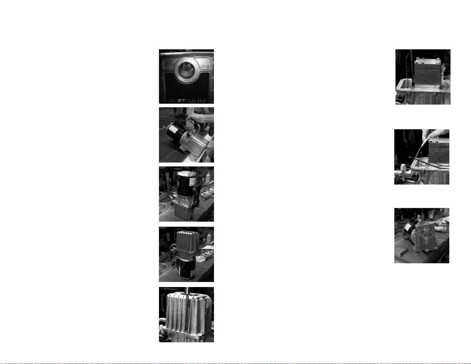
Figure 1
Cleaning and Testing Your Vacuum Pump
One of the easiest ways to spot if your pump is
in need of a good cleaning is to look at the sight
glass. If the oil looks milky, rusty, or full of
debris, then the inside of the pump is in worse
shape (Figure 1).
To clean, start the vacuum pump and allow
it to run for about 15 minutes to warm up the
oil. Make sure that you have allowed enough
working room to safely drain and capture the oil.
After the oil has stopped dripping, tilt the pump
forward to remove any remaining excess oil (Figure 2). Then, stand the pump on the nose of the
cover (Figure 3) to allow any trapped oil in the
wells and stators to drain. Let sit for a few minutes and return the pump to its normal running
position. Repeat tilting forward. Close drain
valve. Dispose of contaminated oil properly.
Once the oil has been completely removed,
return the pump to the position in fi gure 3 and
remove either the 2 rubber feet from the bottom
of the pump or remove pump base (depends on
the age of the pump which option is available).
Next, turn the pump on to the motor end (Figure
4) and remove the 6 socket head cover screws
holding the cover in place (Figure 5). Remove
the cover from the pump and wipe the inside
surface with a dry, clean rag. The sight glass
is more diffi cult to clean. Try pouring in some
solvent and using a pipe cleaner.
Figure 2Figure 3Figure 4Figure 5
Next, remove the oil defl ector which is held in
place with a socket head screw (Figure 6). Wipe
with a clean, dry rag. If needed, a wire brush can
be used to clean any discoloration to metal parts
(this will not affect the pump’s performance once
the cleaning is complete). Remove the cover seal
and clean cover seal (Figure 7). Wipe the outside
of the cartridge’s surfaces with a clean, dry rag. A
wire brush can be used on all surfaces including
the exhaust valve and the intake relief valve. If
they are discolored, they will still perform fi ne.
DO NOT DISTURB THE FOUR CARTRIDGE
BOLTS OR THE TWO SMALLER HEX
HEAD SCREWS (FIGURE 8). These are the
setting screws.
If the intake relief valve set or the exhaust valve
set is damaged and needs replacing, these items
can be ordered through your local wholesaler
under JB Part Number PR-18. It is best to replace
after completing the cleaning of the cartridge. Pay
attention to the order in which they are assembled
for correct reinstallation.
Reassemble the oil defl ector (Figure 6). Clean out
the channel for the cover seal with a clean, dry rag
and smear some grease into the channel. This will
help hold the cover seal in place for reinstallation
of the cover. If the cover seal seems a little tight,
stretch the seal a little and try again. All seals
in JB pumps are designed to be reused. Reset
the cover in place and replace the cover screws.
Tighten in a crisscross pattern. Reattach feet or
base.
Next, return the pump to its normal running position and place where you drained the oil. Open
the drain valve, the 3/8” port on the intake, and the
isolation valve. Have 1/3 cup of clean oil ready.
Start the pump and pour the clean oil into the
intake port. Let the pump run for 5 to 6 seconds
and then shut the pump off. Drain the oil, tipping
the pump forward as in Figure 2 to completely
drain. Close the drain valve and dispose of spent
oil properly after the fl ushing is complete.
Figure 6
Figure 7
Figure 8
DO NOT
DISTURB THESE
Page 3
4 5
Cleaning and Testing Your Vacuum Pump Continued
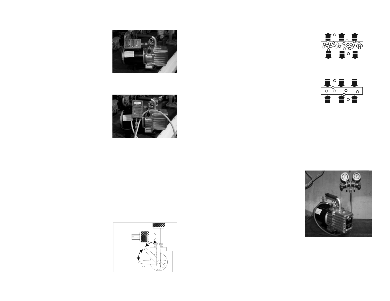
Using Charging and Testing
Hoses for Evacuation
DIRECTION OF PERMEATION
THROUGH HOSE WALL
Now, fi ll the pump to the proper oil
level and allow the pump to run with
the isolation valve closed for 3 or 4
minutes to warm up the oil. Check all
o-ring caps for dirt and proper seal.
Connect a micron gauge (JB recommends the JB DV-22N pictured to the
right) directly to either the 1/4” port or
Figure 9
the 3/8” port on the intake tee (Figure
9). Do not use a charging line. Open
the isolation valve.
Using a charging line, especially a
new line, will give you a higher micron reading because you are reading
the environment inside the hose (see
Figure 10).
Figures 9 and 10 are the same, but
Figure 10
fi gure 9 is a direct connection hook-up
and fi gure 10 is a connection through a new charging line. Both hook-ups are
allowed to run the same length of time, but #9 is at 20 microns while #10 is at
297. If left on, the charging line hook-up will come down in its micron reading,
but it will take a much greater period of time. If the hose is cleaned out with alcohol and vacuumed for a long period of time, the micron reading will go lower.
This test can be performed on a pump with dirty, used oil and then with the
pump cleaned and fl ushed, as described earlier, to see the difference that just
maintaining the cleanliness inside your pump affects the performance for deep
vacuum.
Isolation Valve
It is a quarter turn between on and off.
There is no additional valve needed
to isolate the system. When checking for pressure rise, slowly turn the
handle counter-clockwise. The pause
position is at 45 degrees and the valve
is completely closed at 90 degrees
(Figure 11).
PAUSE
POSITION
CLOSED
POSITION
Figure 11
OPEN
POSITION
You probably think there is a leak. However, an evacuation/ dehydration hook-up
requires a leak-proof design in all of the
components. Only soft copper tubing,
pure rubber hoses, or fl exible metal hoses
are absolutely vacuum tight. Charging
hoses are designed for positive pressure.
CHARGING SYSTEM
Gas under pressure in the hose
will permeate to the lower
pressure of the atmosphere.
Even with the advanced technology of today’s hoses, permeation through the hose
compound still exists (Figure 12).
If you have blanked-off your pump
to check pressure rise and your hoses
and connections are not leak-free, the
atmosphere will permeate to the lower
pressure in the hoses. Your reading will
slowly rise and you will spend time look-
EVACUATION (Hose under Vacuum)
The atmosphere which has a higher
pressure permeates to the lower
pressure in the hose.
Figure 12
ing for system leaks.
Information on Testing the Vacuum Pump’s Isolation Valve
The easiest way to test the isolation valve
for leakage is to turn the pump on with
the isolation valve in the closed position.
Connect a charging line to the center port
of the manifold (Figure 13), and have the
high side capped off and CLOSED and
the low side capped off and OPENED.
Then, connect the charging line to the
intake of the pump and wait. If, within
5 to 10 minutes, you do not see the low
(compound) gauge going into inches of
vacuum, there is no leak in the isolation
valve.
What does happen when a micron gauge
is connected directly to the intake of a vacuum pump with an isolation valve/ It
is all related to the connections to, and including, the intake, the volume of what
is being vacuumed, the depth of vacuum, and the length of time that the volume
is in the deep vacuum.
Figure 13
Page 4

6 7
Information on Testing Vacuum Continued
Brass isolation ball
Stem w/ o-ring
Retainer ring
Figure 14
First, let’s look at the construction of JB’s isolation valve (Figure 14). This fi g-
ure shows the isolation valve in the closed position. The brass ball is sandwiched
between two Tefl on seals, making a positive seal, with a solid brass surface
blocking access to the intake chamber. The adapter nut on the top, outside of the
pump, is where the intake fi tting is connected. It is sealed with Loctite and an o-
ring. If this nut has not been disturbed, the chances of a leak are very minimal.
The stem has a dual o-ring seal and, even if this leaked, with the isolation valve
in the closed position there would be no effect on holding a vacuum. A leak at
the stem would effect the depth of vacuum the pump could achieve.
With a micron gauge connected directly to the intake of the pump and vacuumed
to 50 microns, closing the isolation valve will result in a rapid rise in pressure,
almost to atmosphere. Look closely at the area around the isolation valve. Even
though small, air is trapped in this area. When we begin to close the isolation
valve, there is a position of the ball that allows this trapped air to enter the vacuum being created. On a large system, this small amount of air would not create
a conspicuous change in microns. However, with almost no volume, the sudden
introduction of air to this direct hook-up is obvious and would be displayed on
a micron gauge. Refer to the previous page for the isolation valve positions.
When the isolation valve is put in the pause position, this gives the cartridge
(the pumping mechanism) access to the air trapped in this area and within a few
seconds, that trapped air is removed.
Moving to the connections on the pump, the factory intake is loctited into place
and each pump is tested for leaks. If this is not disturbed, the chances of a leak
Adapter nut w/ o-ring
Teflon seals (2 each)
Retainer Plug w/ o-ring
Poly Ball 7/16”
(oil check system)
are virtually non-existent. Any leak would
come from the connection at the port being
used and to the connection to the system.
One of the most common errors with both
the o-ring and the gasket couplers is the
wrenching down of these couplers with
a pair of pliers or channel locks (Figure
15). Please refer to our “Principles of Deep
Vacuum” article. This article can be found
on JB’s website www.jbind.com under technical information/ troubleshooting. Or type
http://www.jbind.com/tools/userfi les/fi le/
Deep_Vacuum.pdf into your web browser to
take you directly to the page.
As this article shows, there is a need for
sealing with a vacuum tight o-ring (Figure
16). Gaskets, like those used in charging
lines, are made for pressure. What wrenching of the coupler does is to smash the brass
cup that holds the gasket or o-ring against
the male fl are fi tting. This causes the brass
cup to expand outward against the threads of
the coupler and makes it tight to turn. This
causes the o-ring to fall out of the cup that is
holding the o-ring or gasket in place.
Another error that we see is that technicians
have a brass adapter fi tting on the intake of the
pump with no copper gasket. The fi rst time you
wrench the adapter into place, it might seal.
But, as soon as you break the seal and retighten,
there is a chance for a leak. The best hook-up
that guarantees there are no leaks in the system
is by using JB’s DV-29. This hook-up is
depicted in Figure 17. The DV-29 consists of a
fl exible metal hose, ball valve with depressor, a
90° male fl are with coupler, and valve assembly
with male connections. The hook-up and parts
are depicted in JB’s catalog, version 42 on page
13.
Charging lines have been used for many years
for the vacuum end of air conditioning and
refrigeration servicing. Charging line use
Figure 15
DO NOT WRENCH
DOWN COUPLER
Deep Vacuum
O-Ring Coupler Cut-Away
Flare
Fitting
Specially
Designed
Groove
Locks
O-Ring in
Place
Figure 16
Figure 17
45°
Postive
Stop
Page 5

8 9
Information on Testing Vacuum Continued
stretches back as far as when Inches of Mercury (inHg) was the way measuring
of a vacuum on a system was taught. A charging line hose can be vacuumed to
50 microns if it is clean. New environmental hoses, fresh off of the shelf, will
only reach about 300 microns until they are cleaned out with alcohol and vacuumed out for a while. Why is this? First, the charging lines are mostly gaskets
made for positive pressure. Second, they are permeated. See page 5 for how
charging lines and permeation occur. The only vacuum tight hose is a fl exible
metal hose. Third, the compound of the hose inside will outgas when under a
vacuum until it is cleaned out, as discussed earlier.
Another source of leakage is the gasket seal in the valve and hose couplers. This
seal is designed for charging and will not give a perfect seal required in deep
vacuum service. An o-ring seal coupler, like the ones JB makes, forms around
any irregularities in the fl are fi tting. When the coupler is screwed down, we get
a metal to metal seat and the o-ring lies around the lip of the fl are giving it a
positive seal.
If you are used to using a compound gauge when testing for a leak or holding
a vacuum, using a digital gauge will be a little tricky the fi rst time you use it.
Digital vacuum gauges, like JB’s DV-22N, will display microns jumping up and
down in measure. You might think that the gauge is erratic or that there is a leak
in the system. The reason for the changing microns is due to a whole other area
of understanding the environment inside a system being vacuumed. We will
discuss this event in the next section “Information on Digital Micron Gauges”.
To help show the difference of a digital and analog displays in microns, and a
compound gauge display in inches of mercury (inHg) as it relates to their displays of vacuum, we need to hook them up. Take a compound gauge, an analog
gauge, a digital micron gauge, and an empty refrigerant tank. This hook-up is
illustrated on the next page in Figure 18. This allows you to demonstrate the
four components in holding a vacuum: the connections, the volume, the depth
of vacuum, and the length of time that volume is in deep vacuum.
Link all three gauges together by solid brass adapters and o-ring couplers and
couple to the tank. The tank is connected by an o-ring coupler to one of the
intake ports of the pump by way of braided metal hose with o-ring connections.
Then, with the isolation valve in the open position, we can begin to vacuum this
hook-up and watch the readings on the various gauges move into deep vacuum.
Within seconds, the compound gauge’s needle should be nearing 27-29” while
the digital and analog gauge readings are still heading into deeper microns.
After the digital and analog gauges are at 500-600 microns, close the isolation
valve. You will see the digital and analog readings start a pretty rapid rise in
micron readings. Notice that the compound gauge’s needle has not moved.
Figure 18
(NOTE: If the compound gauge’s needle does move toward zero on the scale,
you have an air leak in your connections). Open the isolation valve again and
this time let the hook-up vacuum for 5 minutes. Then close the isolation valve
again and watch. Open the isolation valve for about a minute, then move the
valve to the pause position for about 5 seconds, then close the valve completely.
This removes that trapped air around the isolation valve. You will still see a rise
in pressure, but not as rapid. The readings will start to stabilize the longer this
hook-up is allowed to vacuum down and use the pause position of the isolation
valve the slower and lower the rise in pressure.
If you increase the volume of the cylinder and follow the same procedure, you
will notice a slower and lower rise. If you watch your compound gauge, you
will notice there is no movement.
Page 6

10 11
Information on Digital Micron Gauges
There are three main complaints that are stated on the returns that JB receives
from the DV-22N and DV-24N. First, “inaccurate readings”. Second, “erratic
readings”. Third, “will not hold a vacuum”. Each of these complaints involves
both the understanding of the gauge functions and the principles of vacuum.
Inaccurate Readings: Please note, for the DV-22N and DV-24N we have
a stated accuracy that references AVERAGE accuracy. Thus, between 250 and
6000 microns the unit is +/-10% AVERAGE accuracy and between 50 to 250
microns it is +/-15% AVERAGE accuracy. This does not mean our gauge has a
large accuracy discrepancy.
The term AVERAGE is an important part of this accuracy description. The
number of increments displayed on the JB digital micron gauge between 50 and
250 microns are 97. Between 250 microns and 6000 microns, there are 232 increments. If you take a comparison reading between the DV-22N and the MKS
Baratron master gauge at each of the increments displayed on the Digital micron
gauge the average accuracy would be +/-10% in one range and +/-15% the average in the other range. Also, the number of increments decrease from the lower
micron readings to the higher micron readings.
For example, from 250 to 300 microns there are 16 increments, from 650-700
microns there are only 7 increments, between 1000 and 1050 there are 4 increments, and between 4000 and 4500 there are 4 increments. So at 650 to 700
microns the gauge has the ability to show 650-658-667-675-680-685-690-695.
But at the micron range of 4000 to 4500, the gauge only displays 4125-4250-
4375. This is important because when the system has an actual micron level of
4260, the digital micron gauge will show a reading of 4375 because the threshold for the lower value that the gauge displays, 4250, has not been reached.
Once that threshold has been reached, the gauge will display that lower value
of 4250. Because the readings in these higher micron ranges only need to show
the movement through them , the difference between 4375 and 4250 is of no
concern in reaching the ultimate vacuum desired. This is why the JB DV-22N is
designed with the most increments in range that are going to be the most critical
in determining if the system is ready for charging.
If you understand the size of a micron, then small differences in ranges is nothing to be concerned about. For instance:
Micron Range
60-100
200-350
500-700
900-1500
2500-4000
Micron Difference
10-20
30-40
50-60
80-100
200-300
Information on Digital Micron Gauges Continued
When a DV-22N comes in for repair, it is compared to a secured system set up
with a N.I.S.T. Certifi ed analog gauge (DV-6 Hastings). Usually starting around
(1)60-100 microns, then (2)200-350 microns, then (3)500-700 microns, then
(4)900-1000 microns. These ranges of vacuum are the most common that people work with to determine deep vacuum. We have been comparing the DV-22N
to the N.I.S.T certifi ed gauge on a secured system for a number years and has
proven to be highly accurate in all four ranges of vacuum. The average accuracy
as stated earlier in this section has proven to be consistent against this measure.
Erratic Readings: There are three issues involved in the dis-
cussion of erratic readings. One is the understanding of the gauge’s displayed
micron increments that was just discussed. The second involves the re-sampling
period. The third is the environment inside the system being evacuated. When
the DV-22N is turned on, the display will show “JB” and the sensor will start to
calculate the ambient temperature.
Once the gauge has fi nished calculating the ambient temperature, it will display
the number “1” if it is not introduced to a vacuum level of 9000 microns or less.
Page 7

12 13
Information on Digital Micron Gauges Continued
As the system is being evacuated and the micron level is dropping down through
the increments of the gauge’s display, the gauge will re-sample ambient temperature about every 60 seconds. When this function is taking place, the gauge’s
display will show “auto-cal” (older gauges may see that the display freeze prior
to the re-sampling). The re-sampling lasts for about 15 seconds after which
the micron level that the system is at will then be displayed. For instance, the
system is at a micron level of 5500, the re-sampling begins, the “auto-cal” will
be displayed until the re-sampling is done, then the micron level at which the
system is at will be displayed.
There is also instability inside the system being evacuated. Liquids (moisture)
are being turned into gasses and molecules are moving at different rates of collision with other molecules at different areas of the system at different times
between the high and low sides. The deeper the vacuum, the further apart these
molecules get and the less rubbing together. This decrease in friction changes
the temperature around those molecules and the DV-22N is registering those
changes by way of temperature changes at the sensor’s fi lament. The environ-
ment inside a system being evacuated has more instability at higher micron
levels (9000 to 1000) than at lower micron levels (700 to 50). This is evidenced
when testing the DV-22N at the different ranges on a secured system. When
in the range of 4000 microns, the DV-22N’s display will show 4000 microns,
then jump to 4350, then regress to 3875, then jump back to 4000. After being
blanked-off at this level for a period of time, the changing back and forth will
level out to changing from the incremental display of 4000 microns and the next
incremental display up or down of either 4125 or 3875. But, when in a deeper
vacuum like 350 microns, the changes in display on increments may be from
350 to 357 and back down to 350 or even 329 as the environment inside the
system becomes more stable and the time period of these changes will be less as
most of the out gassing has been done.
Won’t Hold a Vacuum: The sensors on JB’s DV-22 digital gauges are brass
with the sensor components sealed like a light bulb. The area where the hook
shaped wire and the fi lament attach to the sensor’s body is sealed with a glass
like epoxy. The chances of this leaking are next to impossible. The rise in
pressure experienced in the use of vacuum gauges on systems is discussed on
the previous pages under “Information on Testing a Vacuum Pump’s Isolation
Valve”.
Breaking Vacuum
Breaking vacuum prior to shut down is important on larger cfm pumps. This
procedure relieves the stress on the fl exible coupler on the next start up. When a
pump is shut down without breaking vacuum, the oil in the cover is pulled back
into the cartridge and intake chamber of the pump trying to fi ll the vacuum there.
Upon the next start up the pump has to clear the oil outof these areas and all the
stress is on the fl exible part of the coupler, especially if the oil is cold. You can
see this occuring by shutting down the pump and watching the sight glass. The
oil will start to drop down and appears as if you are low on oil. Then when you
restart the pump the oil level returns to normal.
To break vaccum on the Platinum pumps, simply close the isolation valve with
the pump still running and open the gas ballast valve all the way and allow the
pump to run 2-3 seconds with the gas ballast valve opened and then shut pump
off and close the valve.
To break vacuum on the Eliminator pumps. After blanking off at the manifold
or an external isolation valve, if used, crack open the un-used intake port on the
pump and allow to run 2-3 seconds and shut pump off.
Flexible Coupler
On an analog gauge, at a micron
level of vacuum of 4000, the distance
between 4000 and 4350 is between
2T and 5T. This is a distance of about
1/16th of an inch. This distance on
other gauges may vary. Fluctuations
of the needle as the out-gassing is
happening are barely noticeable. The
downside of the analog gauge is that
magnifi cation of the needle is needed
in order to see it move between
the two increments at this range or
vacuum level (4000-4350 or 2T-5T).
Flexible couplers are a three part assembly: 2 metal hubs that look like gears
and a fl exible middle section. The one hub is attached to the shaft of the motor
and the other is attached to the shaft of the cartridge. NOTE: The color of the
fl exible middle section can be either black or yellow.
1 1/2”
7/8”
PR-208
PR-6
Middle section of PR-208 only can
be ordered seperatley PR-308
1 5/8” 2 1/4”
PR-53
2 1/8”
2 3/4”
Page 8

14 15
Replacing Coupler (Motor Removed)
Coat setscrew threads with removable thread sealant. Align coupler setscrew
with fl at surface of cartridge shaft. Tighten screw so coupler slides on to shaft
but stops at the bottom of the fl at. Tighten until screw head is fl ush with coupler
surface (approx. 40 in. lbs.).
Troubleshooting: Pump Hard to Start
Possible cause: Pump has not been shut down properly.
Step 1: Remove 1/4” cap.
Step 2: Move blank-off valve to OPEN position
Step 3: Turn pump on
Step 4: Run 2 to 3 seconds and close blank-off valve.
1/8"
Bottom
Of Flat
Incorrect
Correct
Sight Glass Repair
Step 1: With cover off of the pump,
lay on two blocks of wood. Pop out
the sight glass using a broom handle or
other objects as a punch. For DV-85
series, DV-142 series, or DV-200 series
use a 1” diameter punch.
Step 2: Clean the surface with acetone
or nail polish remover. Put loctite on the
inside surface of the hole.
Step 3: Install the new sight glass from
OIL
LEVEL
NEW STYLE
SIGHT GLA S S
the outside. The hole position does not
matter with the new style sight glass.
Step 4: With the wood block covering
the sight glass, tap the sight glass into
place. Replace the cover on the pump.
Troubleshooting: Poor Pull Down
Possible cause: Check oil level
Possible cause: Missing or damages seals or o-rings
In order for your pump to pull to a near perfect vacuum, oil must be clean and
moisture-free throughout evacuation.
Step 1: With isolation valve closed, start pump. Oil level should be to the top of
the oil level line embossed on the front of the pump’s cover. Just a teaspoon low
can affect the ultimate vacuum.
Step 2: Flush pump and refi ll with fresh oil. See Cleaning and Testing Pump
Section for review.
Step 3: Check all connections to pump and system for damaged or missing orings. If brass adapters are being used, make sure copper gaskets are in place.
READ THE INSTRUCTION MANUAL FOR PROPER
START UP AND SHUT DOWN PROCEDURES.
OPEN
Step 1: Close blank-off valve.
Step 2: Open gas ballast valve.
Step 3: Run 2 to 3 seconds.
Step 4: Shut pump off.
PAUSE
POSITION
CLOSED
POSITION
POSITION
Step 5: Close gas ballast valve.
NOTE: See previously discussed topic “Breaking Vacuum”
Troubleshooting: Motor Just Hums
Possible Cause: If pump has been dropped, the armature in motor may be out of
alignment with the motor’s bell housing.
Step 1: Set pump on bench with motor standing up (Figure 3 of this booklet)
Step 2: Loosen the four motor bolts
Step 3: Shake motor and re-tighten motor bolts
Step 4: Start pump.
If this doesn’t work, the pump most likely will need to be sent in for repair.
Troubleshooting: Motor Runs but No Suction
Possible Cause: Flexible coupler is either broken or loose.
Step 1: Set pump on bench with motor standing up (Figure 3 of this booklet)
Step 2: Look between motor and pump housing from the bottom to see if the
fl exible part of the coupler is split or broken. If it is broken, see “Flexible Coupler” section of this booklet. If the coupler is not broken, the coupler may be
spinning on either the shaft to motor or cartridge.
Step 3: Go to www.jbind.com and on the tool bar go to Technical. Select
instruction sheets from the drop down menu and go to cartridge replacement instructions. These instructions are good for replacing: fl exible couplers, motors,
shaft seals, and cartridges.
Page 9

Cross reference of Vacuum Measurements
Boiling Temperatures of Water at Converted Pressures
Temp. F°
212
205
194
176
158
140
122
104
86
80
76
72
69
64
59
53
45
32
21
6
-24
-35
-60
-70
-90
Microns
759,968
535,000
525,526
355,092
233,680
149,352
92,456
55,118
31,750
25,400
22,860
20,320
17,780
15,240
12,700
10,160
7,620
4,572
2,540
1,270
254
127
25.4
12.7
2.5
0.00
Inches of Hg
Vacuum
0.00
4.92
9.23
15.94
20.72
24.04
26.28
27.75
28.67
28.92
29.02
29.12
29.22
29.32
29.42
29.52
29.62
29.74
29.82
29.87
29.91
29.915
29.919
29.9195
29.9199
29.92
Pressure
Pounds Sq. In.
14.696
12.279
10.162
6.866
4.519
2.888
1.788
1.066
0.614
0.491
0.442
0.393
0.344
0.295
0.246
0.196
0.147
0.088
0.049
0.0245
0.0049
0.00245
0.00049
0.00024
0.00005
0.00000
JB Industries
Technical Support
800-323-0811
www.jbind.com
Form 10710-308
© 2009 JB Industries
MADE IN THE USA
 Loading...