

Page 1
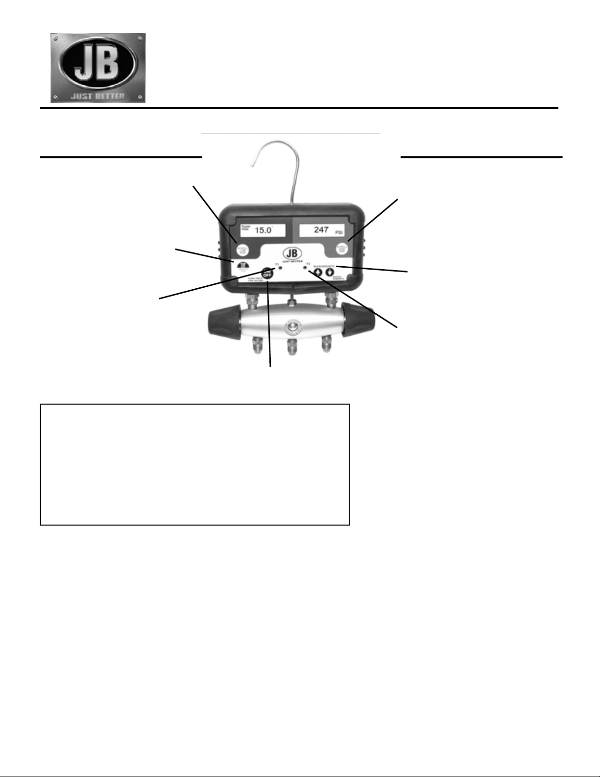
Digital Manifold
Superheat/Subcooling, Charging/Testing Manifold
& Operating Instructions
®
NOT INTENDED FOR USE ON HAZARDOUS OR CORROSIVE FLUIDS
LOW SIDE DISPLAYS
PRESSURE, SUPERHEAT,
TEMPERATURE (T1) and SATURATION
TEMPERATURE
PUSH to toggle between displays
PUSH once to display MAXIMUM,
MINIMUM and AVERAGE values of
current displays
HOLD DOWN to clear memories
Use Temperature Jack (T1) for
Superheat Testing
Uses one or two 9v Alkaline batteries
(Two batteries included)
Batteries can be replaced by taking
off the back of the box
GAUGE SPECIFICATIONS:
Pressure display range: 29 InHg to 600 psig (-98kPa to 4134 kPa)
(+/- 1 PSI to 200 psi, 0.5% to 600 psi)
Temperature display range: -40 °F to 200°F (-40°C to 93 °C)
Operating temperature: -10°F to 120°F (-12 °C to 49 °C)
(+/- 1 °F * 32°F/120 °F, +/- 1.5 °F * -10 °F/32 °F)
Maximum overpressure: 800 psig (5512 kPa)
Battery life and type: 6 Months with two 9v Alkaline battery
Auto-shutoff time: 60 minutes (extended 60 minutes by any button touch)
24 hour mode also available
Refrigerant data source: NIST REF PROP software and manufacturers data
PUSH once to turn ON or OFF
PUSH twice to select 1 hr/24 hr mode
HIGH SIDE DISPLAYS
PRESSURE, SUBCOOLING and
TEMPERATURE (T2), and (T1-T2)
DIFFERENCE
PUSH to toggle between displays
PUSH to select refrigerant (32 available)
HOLD DOWN to change units to Metric
or English
Use Temperature Jack (T2) for
Subcooling Testing
REFRIGERANT PLUG-IN
The manifold holds up to 32 refrigerants.
These are contained in a replaceable plug-in
part. This is servicable by manufacture only.
A list of refrigerants included with the stock
manifold is shown on page 4.
APPLICATION TIPS:
Zero Before Pressure Is Applied
Allow the manifold to Zero at Turn-On: The manifold displays
will zero each time the manifold is turned on without
pressure. Zeroing the gauge compensates the Pressure
display for changes in (1) Altitude and (2) Barometric pressure.
Pressure Calibration
Don't be alarmed if your digital manifold does not agree with
your mechanical gauges. The digital manifold is calibrated
with a very accurate pressure and is not affected by vibration,
motion or position.
Extending On-Time
The digital manifold will turn off automatically after 60
minutes to save battery life. If any button is touched, the
manifold will stay on for another 60 minutes.
The on time can be extended to 24 hours by pushing the ONOFF button 2 times quickly.
Over/Under-Range Indicator
Pressures or temperatures below or above the rated
ranges will cause a “1” to be displayed.
Low Battery Indicator
Low batteries will be indicated by a blinking display and/or
faded numbers.
Batteries For Low Temperature Applications
Using standard batteries in low temperature condtions
will shorten the life. Change to 9 volt lithium batteries
(Radio Shack part number 23-665) to get longer life.
Page 2
Page 3

CHARGING BY THE SUBCOOLING METHOD
Designed For:
13 SEER and other High efficiency Air Conditioning Systems
Large Commercial A/C Rooftop Packages
Refrigeration Systems
PLUG INTO T2 JACK
SCROLL
HIGH
FOR SUBCOOLING
SIDE
JB
T2
T1
REFRIGERANTS
QC RESTRICTOR
FITTING
SCROLL
LOW
SIDE
PUSH
FOR
AVG.
HOLD TO
CLR
ON/
OFF
CONDENSING
UNIT
TO LIQUID LINE
SERVICE VALVE
LIQUID LINE
SUCTION LINE
TEMPERATURE
SENSOR
REFRIGERANT
TANK
TO SUCTION
SERVICE VALVE
SYSTEMS WITH TXV AND NO RECEIVER
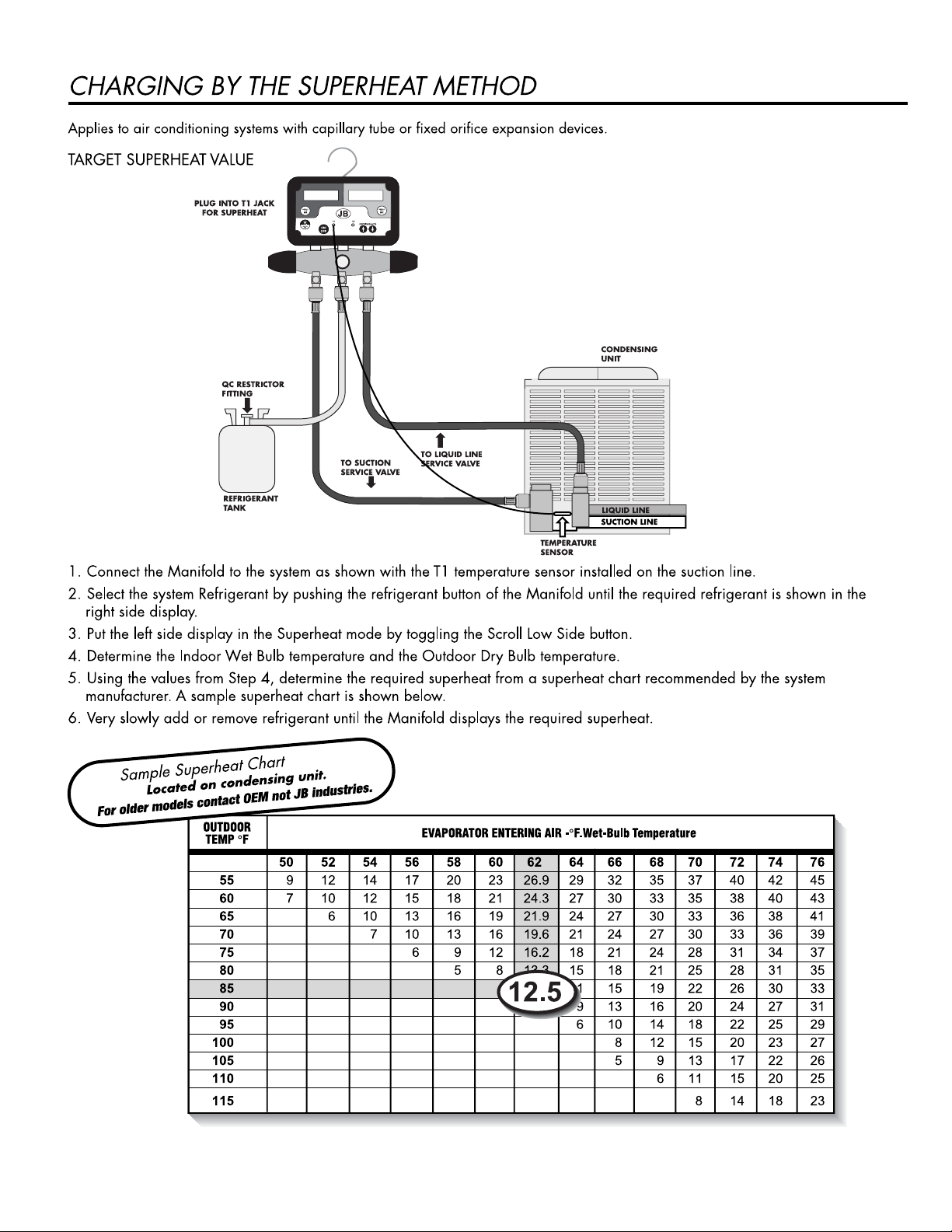
1. Connect the Manifold to the system as shown with the T2 temperature sensor installed on the liquid line.
2. Select the system refrigerant by pushing the refrigerant button of the Manifold until the required refrigerant is shown in the
right side display.
3. Put the right side display in the Subcooling mode by toggling the Scroll High Side button.
4. Determine the required subcooling for the system as recommended by the manufacturer or wholesaler. 10˚F - 12˚F are
typical values.
5. Very slowly add or remove refrigerant until the Manifold displays the required subcooling.
13 SEER high efficiency air conditioning systems equipped with a TXV expansion device require a minimum subcooling value to
insure solid liquid at the expansion valve. These systems often use the bottom tubes of the condenser as a refrigerant receiver.
As a result the amount of refrigerant charge is critical. Too much charge will result in high head pressures during summer
operation. Too little charge will cause flash gas in the liquid line and reduce cooling ability.
Pipe as shown with a temperature sensor on the liquid line. Toggle to Subcooling using the Scroll High Side button to display the
subcooling value. Very slowly add or remove refrigerant to obtain the manufacturers target subcooling value. Allow the system
to stabilize for 20 minutes after adding or removing refrigerant charge before retesting for subcooling.
Many manufacturers use 10°F subcooling as an acceptable value but the actual subcooling value must take into account the fact
that the liquid refrigerant at the TXV must be solid liquid. The liquid line vertical rise and the long liquid line runs will also affect
the required subcooling. See the system manufacturers instructions for the amount of subcooling required to compensate for
these installation situations.
Page 4

SYSTEM APPLICATIONS
– Use for Thermostat controlled supermarket cases and coolers by monitoring the Average temperature. By this method, obtain
the most accurate Thermostat setting.
– Use the High and Low pressure display to accurately set the low pressure cut-in and cut-out values for pressure controlled
cases and coolers.
– Apply the two temperature sensors, with the Manifold toggled to show the T1-T2 Differential temperature, to measure
temperature drop across a cooling coil.
– Use a wet sock over a temperature sensor to measure the Wet Bulb temperature.
A/C & REFRIGERATION APPLICATIONS
Contact your TXV manufacturer for the exact superheat adjust rate.
CHECKING TXV SETTING
The objectives of the TXV superheat setting is to prevent
liquid refrigerant floodback to the compressor and to optimize
system operation by the use of a selected setting.
The two temperature method of measuring superheat is
not recommended because it can produce a wrong
superheat measurement, due to the effect of temperature
glide of the blended refrigerants and variations in evaporator
pressure drop.
NEW RESIDENTIAL A/C SYSTEMS
For new installations of residential A/C systems, the precharge will not provide an accurate amount of refrigerant
charge because of the variation in the length of liquid and
suction line connecting to the “A” coil.
RETROFITTING SYSTEMS
Retrofitting systems to a new refrigerant can change the
TXV superheat setting. The superheat setting should be
checked before and after retrofitting to be sure the superheat
is right for the equipment.
AVAILABLE REFRIGERANTS
R12
R22
R134a
R290
R401A
R401B
R402A
R402B
R403B
R404A
R406A
R407A
R407B
R407C
R408A
R409A
R410A
R411C
R413A
R414B
R416A
R417A * New addition
R422A
R422B * New addition
R422C * New addition
R422D * New addition
R427A * New addition
R428A * New addition
R438A * New addition o
R502
R507
R508B
SET SUPERHEAT
FOR “HUNTING”
TXV VALVES
In refrigeration and
air conditioning
systems, the
expansion valve often
operates to produce
an evaporator
superheat which
constantly swings up
and down in value,
called “hunting.” The
DM-2 provides the
“Average” superheat
value to use for TXV
20
18
16
14
12
10
8
Superheat in °F
6
4
0 5 10 15 20 25
Time in Minutes
Expansion Valve Superheat
DM-2 Average Superheat
Hussmann RHFA 4 DoorFF Case
1 Ton Low Temp.TXC
-2 F Case Temperature
40% HeaterLoad
valve adjustment.
REPLACEMENT ITEMS
PART NO. DESCRIPTION
SH-56 Socks (5)
ACCESSORIES
SH-59 6' Temperature Sensor Clamp
SH-60 6' Temperature Sensor
w/ right elbow (made for DM)
Warranty Information:
Unit has 1 year over the counter warranty due to
Manufacturing defects with proof of purchase.
Customer abuse/neglect not related to
Manufacturing quality will void warranty.
Form 10728-308
Printed in U.S.A.
2010 JB Industries Inc.
E-Mail: sales@jbind.com
Web Site: www.jbind.com
JB INDUSTRIES INC.
Aurora, Illinois 60505 USA
®
 Loading...