

I
I
NNSSTTAALLLLAATTIIOON
N
,
,
UUSSEE AANNDD
MMAAIINNTTEENNAANNCCEE MMAANNUUAAL
L
EN
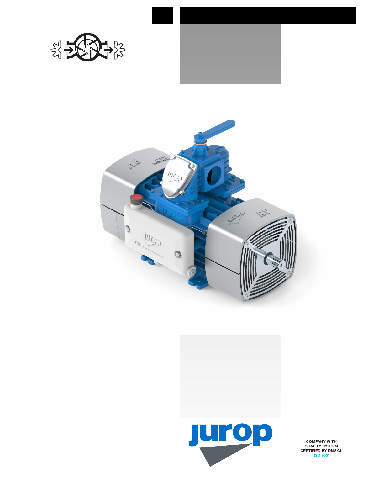
RV360
-
RV520
Rev. 0
9
21-03-2016
O
O
RRIIGGIINNAALL IINNSSTTRRUUCCTTIIOONNS
S

I
NSTALLATION, USE AND MAINTENANCE MANUAL –
RV360 - 520
REV. 0
9
21-03-2016
2 / 32
Jurop
SpA
Via Crosera n° 50
33082 Azzano Decimo, PN (Italia)
TEL. +39 0
434 636811
FAX.
+39 0
434 636812
http://www.jurop.it
e-mail: info@jurop.it
2016 –
Jurop
–
Azzano Decimo (PN)
Reproduction, electronic storage and dissemination, even partial, are prohibited.
Jurop reserves the right to modify the products described in this manual without prior notice.
Any product names mentioned herein are the trademarks of their respective owners.

I
NSTALLATION, USE AND MAINTENANCE MANUAL –
RV360 - 520
REV. 09
21-03-2016
3 / 32
Jurop
SpA
Via Crosera n° 50
33082 Azzano Decimo, PN (Italia)
TEL. +39 0
434 636811
FAX.
+39 0
434 636812
http://www.jurop.it
e-mail: info@jurop.it
Contents
1. General warnings
pag. 4
1.1 Introduction 4
1.2 Spare part request 4
1.3 Warranty terms and conditions 4
2. Technical data
pag. 5
2.1 Dimensions and arrangement RV 360-520 5
2.2 Dimensions and arrangement accessories 7
2.3 Performances 8
2.4 Usage Limitations 8
2.5 Lubrication 8
3. Safety and accident prevention
pag. 9
3.1 General recommendations 9
3.2 Intended use 9
4. Installation
pag. 9
4.1 Checking upon receipt 10
4.2 Storing in the warehouse 10
4.3 Mounting 11
4.4 Vacuum – pressure line 11
4.5 Hydraulic actuator adjustment 11
4.6 Pneumatic actuator adjustment 11
4.7 Pump mounting - Drive connection 12
5. Start up
pag. 13
5.1 Starting-up of the pump 13
5.2 Precautions when starting the system 13
5.3 Precautions of use 13
6. Maintenance
pag. 14
6.1 Ordinary maintenance 14
6.2 Extraordinary maintenance 15
7.
Malfunctions:
troubleshooting
pag. 19
8. Scrapping
pag. 19
S
PARE PART DATA SHEET – RV
360 20
S
PARE PART DATA SHEET – RV
360 -
ACCESSORIES
22
S
PARE PART DATA SHEET – RV
520 24
S
PARE PART DATA SHEET – RV
520 -
ACCESSORIES
26
9.
Cooling fans installation
instructions
pag. 29

I
NSTALLATION, USE AND MAINTENANCE MANUAL –
RV360 - 520
REV. 0
9
21-03-2016
4 / 32
Jurop
SpA
Via Crosera n° 50
33082 Azzano Decimo, PN (Italia)
TEL. +39 0
434 636811
FAX.
+39 0
434 636812
http://www.jurop.it
e-mail: info@jurop.it
1.1 Introduction
• This booklet contains the necessary instructions for a correct
installation, running, use and maintenance of the pump, as well as
some practical suggestions for a safe operating.
• The knowledge of the following pages will grant a long and
trouble-free operation of the pump.
• Following the instructions below contributes to limiting pump repair
expenses by extending its duration, as well as preventing hazardous
situations, thereby increasing its reliability.
• It is recommended to:
• Understand and apply carefully the instructions before running the
pump.
• Keep the booklet at hand and have it known to all operators.
Below is a brief description of the symbols used in this manual.
If these safety rules are not respected, operators can
be injured and the pump or oilers damaged
remarkably.
If these safety rules are not respected, the pump or
system can be damaged.
Suggestions for an environment friendly use of the
pump.
Suggestions for an environment friendly use of the
pump.
• The graphic representations and photographs contained in this
manual are there to illustrate the product in the parts that make it up
and in specific operating phases. Though the model shown in the
manual may differ from the one purchased, the operating principle at
the base of the illustrated operating phase is the same.
• Pump has to be fitted with its own tag reporting the following data:
Model, Serial number, Year, Max speed, Max pressure.
Pic. 1.1
1.2 Spare part request
• Use only genuine spare parts for maintenance and repairs. To
order spare parts, provide the following details:
EXAMPLE:
a) The model of the pump (see pump tag): RV 520
b) The serial number of the pump (see pump tag): K60001
c) A description of the parts (see parts list): V
ANE
d) The quantity (see parts list): n°5 pz
e) The code number of the part (see parts list):
16016 069 00
1.3 Warranty terms and conditions
• Compliance with the installation, use and maintenance instructions
provided by this manual is crucial for the recognition of warranty
against defective parts.
1.
General warnings
I
NSTALLATION, USE AND MAINTENANCE MANUAL –
RV360 - 520
REV. 09
21-03-2016
5 / 32
Jurop
SpA
Via Crosera n° 50
33082 Azzano Decimo, PN (Italia)
TEL. +39 0
434 636811
FAX.
+39 0
434 636812
http://www.jurop.it
e-mail: info@jurop.it
• Rotary vacuum pump cooled by high efficiency contrapposed fans. The airflow reduces the temperature of the internal parts normally
subjected to wear like bearings, vanes and sealings.
• High resistance tangential vanes. Suitable for heavy duty operation.
• Automatic lubrication with positive displacement pump. Side mounted oil tank. Copper oil piping.
• N°2 vane inspection ports.
• Built-in 4-way vacuum/pressure manifold. Pneumatic actuator available on request.
• Non-return valve integrated in the pump manifold (RV360). Check valve installed on the pump inlet (RV520).
• Aluminum conveyors.
• Available in flanged version (FL).
• Drive system:
- Direct with smooth shaft;
- With hydraulic motor.
Weight
RV 360 manifold RV 360 FL RV 520 manifold RV 520 FL
Direct with smooth shaft 175 kg 166 kg 220 kg 210 kg
With hydraulic motor 205 kg 196 kg 250 kg 240 kg
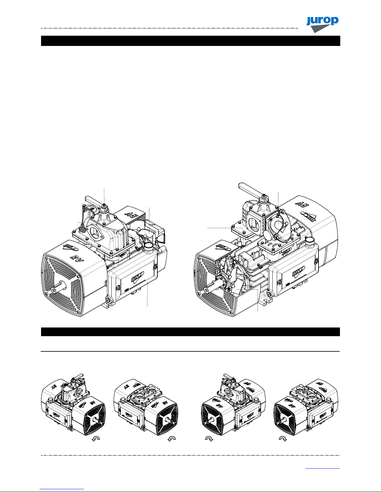
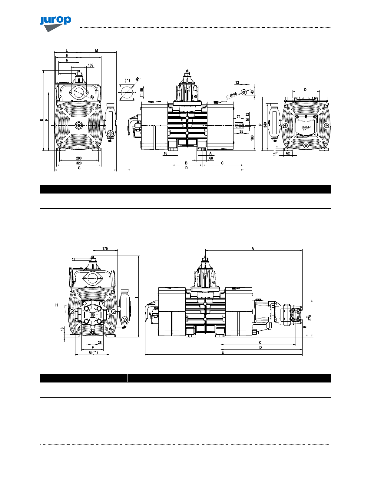
2.1 Dimensions and arrangement RV 360 – RV 520
2.
Technical data
RRV
V
336600
RRV
V
552200
R
OTATION LEFT – WITH MANIFOLD
R
OTATION LEFT – WITH FLANGE
R
OTATION RIGHT – WITH MANIFOLD
R
OTATION RIGHT – WITH FLANGE
FAN
FAN
SIDE MOUNTED
OIL TANK
NON RETURN VALVE
INTEGRATED
4
WAY MANIFOLD
NON RETURN VALVE
INTEGRATED
VANE INSPECTION
PORTS
I
NSTALLATION, USE AND MAINTENANCE MANUAL –
RV360 - 520
REV. 0
9
21-03-2016
6 / 32
Jurop
SpA
Via Crosera n° 50
33082 Azzano Decimo, PN (Italia)
TEL. +39 0
434 636811
FAX.
+39 0
434 636812
http://www.jurop.it
e-mail: info@jurop.it
RV360 – RV520
Dimensions (mm) A B C D E F G H I L M N O P
RV 360 25 220 294 830 577 415 443 168 160 175 267 145 192 384
RV 520 29,5 286 334 975 598 429 438,5 156,5 187,5 160 278,5 195 210 392
(*) : dimension of RV520 manifold
RV360 HDR – RV520 HDR
Dimensions (mm) A B C D E F G ( * ) H (IN) H (OUT) I
RV 360 HDR 686 157 529 576 1111 155 240 G1” ¼ G1” ½ 577
RV 520 HDR 741 149 527 598 1239 150 - G ¾ G1” 597,5
(*) : Dimension referred to RV360 hydraulic motor with flanges version.
F
LANGE VERSION
(FL)
I
NSTALLATION, USE AND MAINTENANCE MANUAL –
RV360 - 520
REV. 09
21-03-2016
7 / 32
Jurop
SpA
Via Crosera n° 50
33082 Azzano Decimo, PN (Italia)
TEL. +39 0
434 636811
FAX.
+39 0
434 636812
http://www.jurop.it
e-mail: info@jurop.it
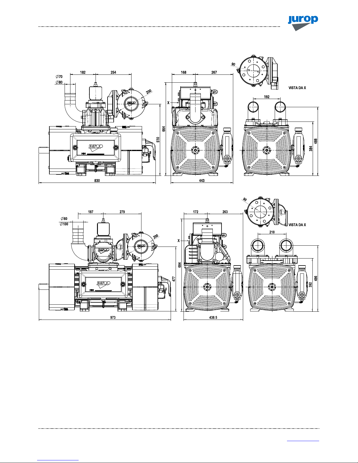
2.2 Dimensions and arrangement - Accessories
RV 360
RV 520

I
NSTALLATION, USE AND MAINTENANCE MANUAL –
RV360 - 520
REV. 0
9
21-03-2016
8 / 32
Jurop
SpA
Via Crosera n° 50
33082 Azzano Decimo, PN (Italia)
TEL. +39 0
434 636811
FAX.
+39 0
434 636812
http://www.jurop.it
e-mail: info@jurop.it
2.3 Performances
Performances referred to vacuum pump operating at max. speed. Actual performance may vary of +/- 5%.
Performances RV 360 RV 520
Air flow under free air condition 10200 l/min – 612 m³/h 14700 l/min - 882 m³/h
Air flow 60% vacuum rate 9400 l/min - 564 m³/h 12915 l/min - 775 m³/h
Max. vacuum at continuous duty 80% 80%
Max. vacuum 95% 95%
Power required at free port 14 kW 19 kW
Power required at max. vacuum 11 kW 16 kW
Airflow at 0.5 relative bar (1.5 abs.) 18 kW 24 kW
Airflow at 1.0 relative bar (2.0 abs.) 22 kW 30 kW
Max. relative pressure 1,0 bar (2,0 bar abs) 1,0 bar (2,0 bar abs)
Oil consumption 140 g/h 160 g/h
Oil tank capacity 4 l 4 l
REFERENCE CONDITIONS
Conveyed gas: air Vacuum condition: atmospheric discharge. Absolute reference pressure: 1013mbar
Ambient reference temperature: 20°C Vacuum functioning: free outlet Pressure condition: atmospheric suction.
Flow / Power
Model Free ports
Vacuum rate Abs. pressure
20% 40% 60% 70% 80% 90% 1,5 bar 1,8 bar 2,0 bar
m3/h 612 605 595 564 453 310 106 570 550 540
RV 360 l/min 10200 10080 9913 9400 7550 5166 1766 9496 9163 8997
kW 14 13,5 13 12,6 12,3 11,9 11,2 18 20,5 22
m3/h 882 860 840 775 670 480 150 780 740 712
RV 520 l/min 14700 14330 14000 12915 11165 8000 2500 13165 12330 11865
kW 19 18,2 17,7 16,9 16,4 16,2 16,1 24 27,5 30
Note: data at nominal speed.
Sound pressure level RV 360 RV 520
Max. speed, 60% vacuum rate* 72 dB(A) 73 dB(A)
* : Noise of pump with exhaust silencer cod. 15470 D2C B0. Distance: 7m in open field.
2.4 Usage limitations
Model
Max. Speed – Operating speed (RPM)
P2 (bar ABS) T2 (°C) T2 - T1 (°C)
Environmental
Temperature
Minimum Ordinary Max
RV 360 800 rpm 1100 rpm 1300 rpm 2,0 bar 180°C 150°C -20 / +40°C
RV 520 800 rpm 1100 rpm 1300 rpm 2,0 bar 180°C 150°C -20 / +40°C
P1: absolute pressure during suction T1: temperature during suction
P2: absolute pressure during delivery T2: temperature during delivery
2.5 Lubrication
Room.
Temp.
Viscosity Type ENI ESSO SHELL TOTAL MOBIL BP
TEXACO
HAVOLINE
Under 10°C ISO VG 46 Mineral oil Acer 46 Nuto 46 Morlina oil 46 Drosera MS 46 Nuto H 46 Bartran HV 46 Rando HD 46
Over 10°C ISO VG 150 Mineral oil Acer 150 Nuto 150 Morlina oil 150 Drosera MS 150 Nuto H 150 Bartran HV 150 Rando HD 150

I
NSTALLATION, USE AND MAINTENANCE MANUAL –
RV360 - 520
REV. 09
21-03-2016
9 / 32
Jurop
SpA
Via Crosera n° 50
33082 Azzano Decimo, PN (Italia)
TEL. +39 0
434 636811
FAX.
+39 0
434 636812
http://www.jurop.it
e-mail: info@jurop.it
Attention:
Carefully apply these prescriptions.
3.1 General recommendations
• Installation and maintenance must be carried out with the unit
totally disengaged from its drive system and must be performed by
qualified personnel.
• Use adequate clothing (avoid ties, loose sleeves, necklaces and
so on) and suitable protection equipments (gloves, protection glasses,
boots...).
• To prevent errors and hazardous situations, establish what each
operator is responsible for in the different maintenance operations.
• When transporting the pump, use proper slinging. Store the pump
in stable places.
• Make sure that all the parts of the unit are idle and cool, before
performing any maintenance operation.
• Before each maintenance operation, stop the pump and restore
the atmospheric pressure.
• When the pump is running, some parts may reach very high
temperatures (above 100°C). Use all necessary precautions to avoid
contact.
• Operators working nearby must avoid prolonged exposure to the
noise emitted by the aspirator, if not equipped with the proper earprotection devices.
• Avoid accidental suction of solids: solids may be projected at high
speed through the exhaust manifold and cause injures. A filter must be
mounted on the sunction line.
• Do not start the machine if the protection devices provided for
transmissions are removed. Replace damaged parts.
• Pressure relief valve: point the air flux away from the operators.
• Do not use the aspirator over its designed limits: the machine may
be damage and the operator may be injured.
Do not exceed the power supply parameters
indicated in the technical tables (see par. 2.4).
3.2 Intended use
• The vacuum pumps RV are designed to convey filtered air into
systems for the vacuum production (example: systems for the suction
of powders or liquid wastes). Any other usage shall be considered
improper.
• Do not sack toxic substances and inflammable or explosive
gasses, since the internal components of the pump may reach high
temperatures.
• Liquids or solids infiltrations can seriously damage the pump.
• Do not run the pump over its designed operating limits (see par.
2.4): it may break and transmission can be damaged.
Legend of main components
1. Manifold 5. Oil Tank 9. Lubrication pump
2. Vacuum-pressure manifold 6. Tank oil stand 10. Cooling fan
3. Non return valve (rubber ball RV 360) 7. Oil filler cap 11. Air cooling conveyors
4. Non return valve (clapet RV 360) 8. Vane inspection ports 12. Fan protection
Pic. 4.1
4. Installation
3.
Safety and accident prevention
1 2
3
11
10
9
7
8
4
5 6
1
2
5 6 10 11 12

I
NSTALLATION, USE AND MAINTENANCE MANUAL –
RV360 - 520
REV. 0
9
21-03-2016
10 / 32
Jurop
SpA
Via Crosera n° 50
33082 Azzano Decimo, PN (Italia)
TEL. +39 0
434 636811
FAX.
+39 0
434 636812
http://www.jurop.it
e-mail: info@jurop.it
4.1 Checking upon receipt
• When the goods are delivered, make sure that all parts in perfect
condition and have suffered no damage during shipping.
• Make sure the vacuum pump has its identification plate affixed on
the front cover. Pumps without such identification are to be considered
anonymous and potentially dangerous: in such an event, they must not
be used, otherwise the manufacturer will be deemed free from any
liability whatsoever.
• Pump must be kept in a dry storage area. During storage, inlet and
outlet ports must be kept closed.
4.2 Storing in the warehouse
• If the pump will not be installed inside a short time after delivery:
- Remove the guards from the ports and spray a film of
protective oil over the inner surfaces of the body, rotors and
sides. Then attach again the guards;
- Store in a closed and dry place. Renew the preserving oil
periodically.
• To temporarily store a used pump, follow the instructions below:
- Thoroughly clean the pump.
- Equip the pump with suitable anti-corrosion protection.
4.3 Mounting
• The mounted aspirator must be accessible for maintenance and
firmly fixed on a frame or angled base with a 3° max inclination on X
and Y axes (see Fig. 4.1). The structure must be fit to avoid flexions or
vibrations.
• Provide enough space for air ventilation and disposal of heat when
pump is running. See Fig. 4.2 and 4.3 for indication of the distance to
be respected.
RV 360 RV 520
Pic. 4.2
• Provide the necessary space to reach all points of lubrication
control (oil level), and the oil tank filler cap, the lever of the 4-way
switch, vanes inspection ports.
• The oil tank is mounted on the suction side of the housing. Thus,
the rotary direction determines the pump overall dimensions. See also
paragraph 2.1.
RV 360
RV 520
Pic. 4.3
• In case of RV with hydraulic motor, provide the necessary space
to disassemble the motor itself and proceed with joint lubrication.
Pic. 4.4

I
NSTALLATION, USE AND MAINTENANCE MANUAL –
RV360 - 520
REV. 09
21-03-2016
11 / 32
Jurop
SpA
Via Crosera n° 50
33082 Azzano Decimo, PN (Italia)
TEL. +39 0
434 636811
FAX.
+39 0
434 636812
http://www.jurop.it
e-mail: info@jurop.it
4.4 Vacuum - pressure line
Pic. 4.5
• See figure 4.5.
• In order to avoid the suction of liquids, a primary flow shutoff valve
(Pos. 1) and a secondary shutoff (Pos. 2) are to be mounted on the
suction line. If necessary, also apply a suction filter (Pos. 3) to prevent
solids from entering.
• The silencer (Pos. 4) applied to the pump exhaust - besides
reducing the noise level - is designed to separate the oil mist expelled
from the pump outlet port. The separator must be easily drained from
oil and condensate accumulated at regular intervals.
• The diameter of the vacuum or pressure line pipes must be
properly dimensioned to the pump flow and, in any case, it must be
larger than the diameter of the ports.
• The pipes weight or their dilatations must not solicit the pump
housing. Use high temperature resistant rubber connections.
• Before mounting, remove the port protections. All pipes and line
components must be clean.
• Avoid restrictions and tight curves as much as possible, if not
strictly necessary.
• Exhaust pipe can reach high temperatures. Hence, they must be
properly isolated.
• An over-pressure safety relief valve (Pos. 5) should be mounted in
order to prevent the overloading of the vacuum pump. Mount the valve
near the pump without applying any gate valves on the line.
• A vacuum relief valve (Pos. 6) should be applied to limit the
maximum vacuum rate at 80% in order to prevent the pump running at
continuous duty from overheating.
• Venting shutter (Pos. 9): it is also useful to cool down the
overheated pumps as well as for their internal wash-up. Direct the air
flow away from the operators.
• Thermostat (Pos. 8): it must be installed at maximum 150 mm from
the exhaust port. The sensitive element must reach the pipe centre.
Safety thermostat on manifold is supplied on request.
4.5 Hydraulic actuator adjustment
• Extraordinary maintenance operations can require the upper cover
(and that of the actuator, either manual or pneumatic) to be removed.
We recommend ensuring enough space to carry out such operations.
• If the cock blocks or it moves with friction, screw up the clearance
regulation nut (A). Screw up ¼ of turn each time. Block the nut rotation
with the safety nut.
• The lubrication points (B) and the clearance regulation bolt (A)
must be accessible. See Fig. 4.6.
• Lubricate with grease every 1000 cycles. Grease type NLGI 2.
• It is suggested to install 2 one‐way flow controller between the
hydraulic switch and the hydraulic actuator. Set the flow controllers in
order to prevent hard hitting through the end of stroke. Minimum
commutation time: 1 second.
• Maximum feed pressure: 30 bar.
• To order spare parts see spare parts list at the end of this manual.
Pic. 4.6
4.6 Pneumatic actuator adjustment
• In the event of 4-way valves equipped with pneumatic actuator, we
recommend installing two one-way flow regulators between the
pneumatic “control” and the pneumatic actuator. The following figure
shows a schematic view of a possible pneumatic installation.
• We recommend adjusting the two flow regulators in order for
rotation to occur without knocks and with a switching time of at least
one second.
Vacuum line components
1 Primary shutoff 6 Vacuum relief valve
2 Secondary shutoff 7 Manometer -1 / +3 bar
3 Suction filter 8 Thermostat
4 Silencer – oil separator 9 Venting shutter
5 Overpressure safety valve
3
2
1
4
5
6
7
9
8

I
NSTALLATION, USE AND MAINTENANCE MANUAL –
RV360 - 520
REV. 0
9
21-03-2016
12 / 32
Jurop
SpA
Via Crosera n° 50
33082 Azzano Decimo, PN (Italia)
TEL. +39 0
434 636811
FAX.
+39 0
434 636812
http://www.jurop.it
e-mail: info@jurop.it
α
α
1
α
α
1
Pic. 4.7
4.7 Pump mounting - Drive connection
A) Cardan shaft drive
• Use telescopic cardan shafts.
Pic. 4.8
• In order to achieve a uniform motion of the driven shaft, the
following requirements must be met (see Pic. 4.8):
- Equal working angle α and α1 of both couplings.
- The internal fork joints must be coplanar.
- Both driven and driving shafts must be coplanar.
• It is also recommended working with limited articulated joint angles
(max 15° at 1000 rpm and max 11° at 1300 rpm) and disengaging the
transmission for those operations requiring great angles (steering or
lifting).
Follow the rotation direction as indicated on the
pump front conveyor protection. Follow the
instructions of the cardan shaft’s manufacturer.
B) Belt drive
Pic. 4.9
• Install a suitable pulley on the smooth shaft as close as possible
to the pump: 50 mm. Taper lock pulley are suggested.
• Apply an adequate belt tension (see manufacturer’s data). See list
belove (T. Max).
• Do not use diven or driving pulleys with a pitch diameter inferior to
160 mm. Small pulleys require a high belt tension, which may cause
premature wear to the bearing or transmission damages.
• Let the air circulate freely to cool down the pump. Provide
protections, which ensure adequate ventilation.
• A limited speed ratio will extend the belts life and reduce stress on
the shafts. When possible prefer:
- Pulleys with a pitch diameter bigger than the one indicated,
Dp=180mm;
- Engines or power take-offs with a speed similar to the one of the
pump.
Model Drive min. pulley p. diam. T. max Belts Max. Speed Max. Pressure Max. Vacuum.
RV 360 160 mm 4000 N XPB x 3 1300 rpm 2 bar abs 95%
RV 520 160 mm 4000 N XPB x 4 1300 rpm 2 bar abs 95%
C) Hydraulic drive
Modell Displacement Operating pressure Flow
Max pressure
draining line
Max. pressure
motor exhaust
Max pressure
RV 360
Vac. Max. 61 cc/rev 130 bar 83 l/min (1300rpm) 5 bar 5 bar 180 bar
0,5 bar rel 61 cc/rev 160 bar 83 l/min (1300rpm) 5 bar 5 bar 180 bar
RV 520
Vac. Max. 72 cc/rev 150 bar 99 l/min (1300rpm) 5 bar 5 bar 250 bar
0,5 bar rel 72 cc/rev 185 bar 99 l/min (1300rpm) 5 bar 5 bar 250 bar
Tc 4000 N
Dp
min 160
KEEP AXELS PARALLEL
ALIGN PULLEY GROVES AND BELTS
CHECK BELT TENSION
F=30 N
f=6 mm
10 mm
50 mm

I
NSTALLATION, USE AND MAINTENANCE MANUAL –
RV360 - 520
REV. 09
21-03-2016
13 / 32
Jurop
SpA
Via Crosera n° 50
33082 Azzano Decimo, PN (Italia)
TEL. +39 0
434 636811
FAX.
+39 0
434 636812
http://www.jurop.it
e-mail: info@jurop.it
5
4
6
1
3
P
A B
OUT IN
DRAINING LINE
3
5
4
6
1
2
• Fluid: mineral oil for hydraulic systems in compliance with ISO/DIN.
Temperature Optimum viscosity ale Max. viscosity allowed
-20 / +80 °C 12 – 100 cSt 750 cSt
• Filtration: class 19/16 contamination according to ISO 4406 to be
obtained with a ßx = 75 filter.
• Check circuit connections: they must be applied in the same
rotation direction as that indicated by the arrow on the pump front
conveyor protection.
Pic. 4.10
• Draining: connect directly to the tank above the maximum oil
level. Operating without draining line may damage the motor.
• Distributor: open-centre distributor in central idle position
(vacuum pump off). It must be equipped with an adjustable
overpressure safety valve.
• Motor pipeline: outlet pipe must not be of a smaller diameter than
that of the inlet port. Inlet pipes always have a diameter smaller than
outlet pipes. Choose preferably flexible pipes to avoid vibration
transmission.
• Tank: with suction pipe and return separated by baffles. If
necessary, use a heat exchanger to avoid oil heating above 70-80°C
and protect it from extreme pressure with a pressure relief valve.
Minimum approximate capacity: as twice as the circulation flow.
Pic. 4.11
1 HDR pump 4 Oil filter
2 Distributor 5 * Heat exchanger
3 HDR motor 6 * Safety valve
* optional components
• Starting-up: be sure that the system is well cleaned and pour oil
into the tank and into the motor housing (necessary to lubricate the
internal bearings).
• Vent the circuit and adjust the overpressure safety valve to the
lowest possible value.
• Check the oil tank level.
• Increase pressure and rotation speed until operating values are
reached.
5.1. Starting-up of the pump
Lubrication
• Check oil levels in rear mounted tank.
• In order to choose the most suitable oil, see paragraph 2.7.
Vacuum line
• Open all valves of the vacuum-pressure system.
• Open all gate valves and remove any possible obstacle from the line.
5.2. Precautions when starting the system
• Check oil levels in gearbox and side mounted tank.
• Check that all protection devices are correctly installed.
• Check that there are no obstacles in the vacuum line.
• Check rotation direction: open all system valves and start running
slowly.
Do not rotate in the wrong direction: this may
damage the vacuum pump. Follow the arrow
indicated on the front flange.
• Check which position of the four-way integrated valve lever allows
vacuum or pressure functioning.
• If the pump has been in storage for a long time: inlet ½ liter of oil in
the pump for an easy cleaning of internal parts.
• Close the valve and increase vacuum rate (or operating pressure).
• Check loading and operating speed for vibrations or unusual
noises.
This vacuum pump is designed to work at
maximum speed, but for longer operating we
recommend the pump be run at working speed
(see par. 2.4).
• To reduce the vacuum rate to 80% max.
• Prepare adequately transmission.
5.3. Operating precautions
• Run the vacuum pump at a room temperature of -20°C e +40°C.
• Running at continuous duty: see paragraph 2.5.
• Do not make the vacuum pump overheat. Maximum air
temperature on exhaust (or delivery) side: 180°C.
• If maximum temperature allowed is reached, in order to prevent
damages to the internal parts, it is recommended:
- To reduce the vacuum rate or the working pressure by opening
the venting port;
- To reduce the pump speed according to list at paragraph 2.6.
5. Start up

I
NSTALLATION, USE AND MAINTENANCE MANUAL –
RV360 - 520
REV. 0
9
21-03-2016
14 / 32
Jurop
SpA
Via Crosera n° 50
33082 Azzano Decimo, PN (Italia)
TEL. +39 0
434 636811
FAX.
+39 0
434 636812
http://www.jurop.it
e-mail: info@jurop.it
- To start running the pump again only when temperature at
exhaust is below acceptable values.
• Do not operate the pump without lubrication: it may cause quick
wear and possible breakdown of vanes.
• Do not start running the pump under load: that causes stress to the
drive system and the hydraulic motor.
• Check rotation speed. The vacuum pump must:
- never exceed the maximum speed: it may cause overheating;
- never run below the minimum speed: this may cause an
anomalous wear of the housing.
• Do not accidentally operate the pump in the wrong direction: it may
break the vanes.
• Do not convey the exceeding delivery outlet towards the suction
port, otherwise it will sack warm gas.
• In vehicles do not direct compressor’s discharge to the intake of
the engine.
• Control the air flow by adjusting the rotation speed: do not use the
pressure relief valve to discharge the exceeding flow.
• Internal wash-up is necessary after prolonged inactivity, after
working in dusty environments or in case of accidental suction of
liquids.
Such operation must be carried out only on cooled pumps.
1. Disconnect the exhaust silencer, if possible;
2. Start running the pump at low speed (500 rpm circa) and low
vacuum (20-30% max);
3. Suck some water (about 1-2 litres) through the inlet port;
Then suck oil (about 1 litre) to complete the wash-up and lubricate
internal components.
In case the exhaust line cannot be disconnected,
drain the liquids accumulated in the separator of
the exhaust silencer.
• Once the needed vacuum rate has been reached, we recommend
reducing the vacuum pump speed to its working speed (see par. 2.6):
this allows keeping the achieved vacuum/pressure rate constant. The
pump speed can also be reduced to values lower than the working
speed during the tank discharging phase (with the 4-way valve in
pressure mode) without increasing the draining time.
• Thus, exhaust temperature is reduced, vane durability is increased
and both oil consumption and power absorption are reduced.
Once the needed vacuum rate has been reached,
we recommend reducing the vacuum pump
speed to its working speed.
6.1 Ordinary maintenance
• Installation and maintenance must be operated only by qualified personnel wearing the proper clothes and the necessary tools as well as
protection devices.
• Use suitable protection equipment (gloves, protection glasses, boots...)
• In the following table summarizes the main controls to be performed and the frequency of intervention.
Operating Condition Maintenance Area Check 8H 50H 500H 1000H
O
PERATING
Vacuum Line
Operating pressure
Check safety valve
Transmission / Pump
Rotation speed
Sound pressure level (also HDR motor)
S
TANDSTILL
Vacuum Line
Drain the oil gathered in the exhaust separator
Clean filter and vacuum line shutoff
4-way changeover valve: check and lubricate
Clean suction filter
Pump
Side mounted tank oil level
Clean fan protections
Check vanes wear
Pump’s inner washing (*)
Overall
Greasing
Check cardan shaft drive
Chack transmission pulley
(*) After operation in dusty environments, after accidental sucking of liquids inside the pump or before a long inoperativity period it is recommended to wash the pump
inside. See paragraph 5.3.
6. Maintenance
I
NSTALLATION, USE AND MAINTENANCE MANUAL –
RV360 - 520
REV. 09
21-03-2016
15 / 32
Jurop
SpA
Via Crosera n° 50
33082 Azzano Decimo, PN (Italia)
TEL. +39 0
434 636811
FAX.
+39 0
434 636812
http://www.jurop.it
e-mail: info@jurop.it
Checking lubrification
• Check the correct operation of the system / lubrication circuit.
If the pump is running without lubrication, the
internal components may quickly damaged due to
overheating. Stop the vacuum pump and check the
oil level and the lubricating pump.
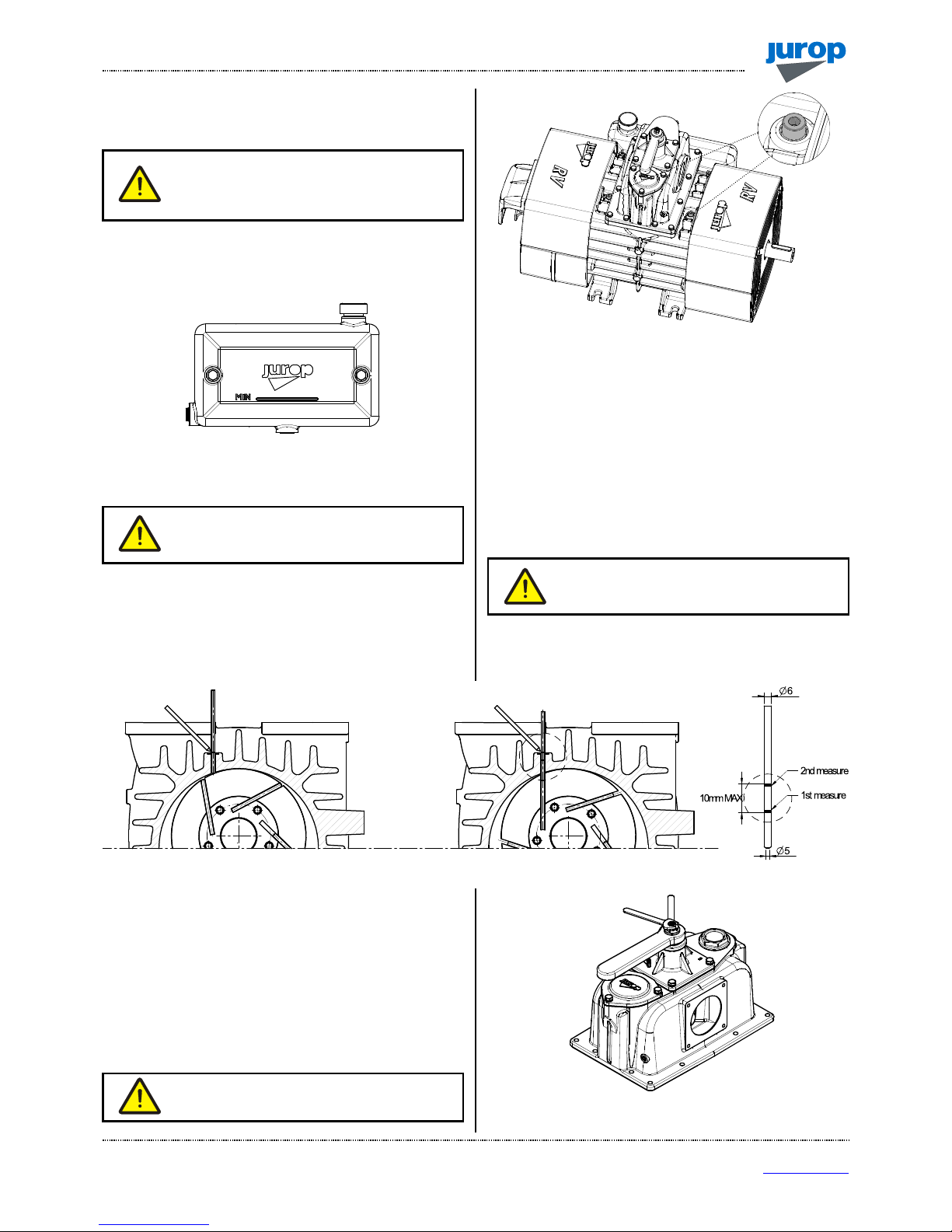
Checking the rear mounted oil tank level
• Do not run the pump with oil level under the minimum level: that may
lead to dry functioning and cause serious damages. See Fig. 6.1.
Pic. 6.1
• Tank capacity: 4l.
• Use pure fresh oil.
Do not re-use the exhausted oil gathered on the
bottom of the exhaust silencer.
Checking the vanes wear
• Unscrew the vanes wear check-plug on the front flange. See Fig.
6.2.
• Turn the shaft by hand until vanes appearance.
• Vanes usually slip on seat bottom due to gravity. Check their right
entry in the seat.
Pic. 6.2
• Insert a Ø 5 mm stick until it touches the rotor and then mark (see
Fig. 6.3).
• Turn the rotor slowly until the stick touches the vane in idle
position in its seat. The vanes slide to the bottom of the seat due to
gravity: check they really do and mark again on the stick.
• Repeat the same procedure for all the vanes. If wear exceeds 10
mm: replace the vanes as soon as possible.
• Maximum acceptable wear: 12 mm. Immediately replace: vanes
are likely to break down.
• Replace all the pump vanes at the same time.
Replace the vanes when their wear exceeds 12
mm (L – L min): they may break. Replace all
vanes at the same time.
• Replace the cap after the measurement.
Pic. 6.3
6.2. Extraordinary maintenance
• Before starting any extraordinary maintenance operation, be sure
the pump stands still and follow the safety prescriptions as described in
Cap. “Safety and accident prevention”.
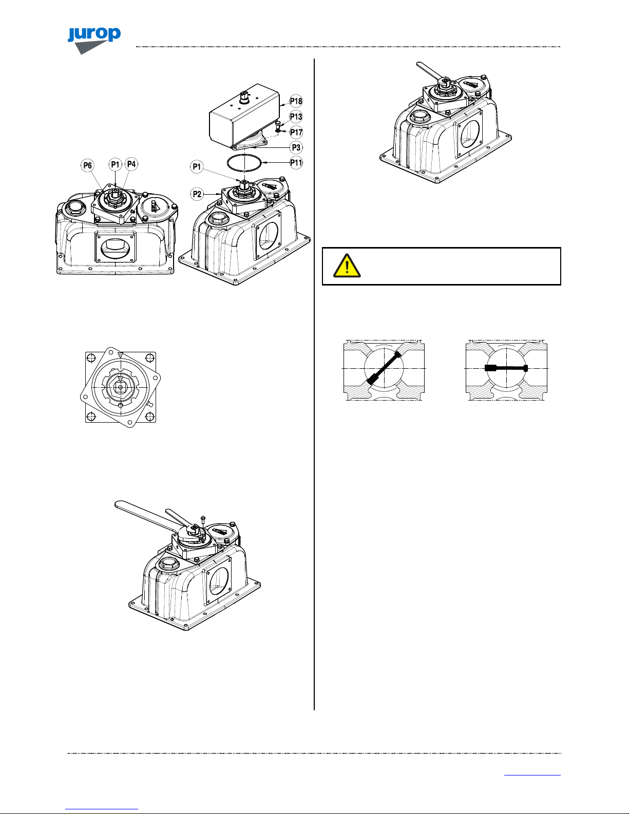
Adjusting the 4-way valve
• For pumps equipped with handle for manual operation or actuator.
• Adjust the screws to avoid the valve blocking in its seat (see Fig. 6.4).
Attention: do not exceed with the adjustment:
possible vacuum loss
Pic. 6.4
V
ANES WEAR
CHECK-PLUG
I
NSTALLATION, USE AND MAINTENANCE MANUAL –
RV360 - 520
REV. 0
9
21-03-2016
16 / 32
Jurop
SpA
Via Crosera n° 50
33082 Azzano Decimo, PN (Italia)
TEL. +39 0
434 636811
FAX.
+39 0
434 636812
http://www.jurop.it
e-mail: info@jurop.it
Adjusting the pneumatically operated 4-way valve
• In case of reduced
performance or difficult rotation of
the valve in its seat, it is necessary
to adjust the operating play.
Pic. 6.5
• Unscrew the 4 screws M8x16 which fasten the top cover (P3) to
the inferior support (P2).
• Clean the inner part from the lubricant.
“Mark” the initial position of the
cock (P1). When mounting the
cock back in place, it must be in
the same position.
• Turn the valve until one of the cock regulation ferrules (P6)
coincides with one of the threaded holes on the inferior flange (P2).
Block temporarily the nut ferrule with a screw.
• Hold the valve in place with a 17 mm spanner and loosen the nut
(P4) over the ferrule by ½ - ¾ turn with a 36 mm spanner.
Pic. 6.6
• Valve adjustment: turn the valve clockwise by 1/8 turn (45°) in
order to lower it (in case of excessive play between the valve and its
seat and of reduced performance) or anticlockwise by 1/8 turn (45°) to
raise it (in case of difficult rotation of the valve in its seat).
• Hold the valve in place with the spanner and fasten the nut (P4)
above the ferrule.
Pic. 6.7
• Remove the screw which temporarily blocks the ferrule and check
for the correct rotation of the valve by adjusting the shaft frame. Repeat
the valve adjustment, if necessary.
Attention: get the valve back into the previously
“marked” position. Otherwise, the valve may
work improperly.
• The valve - in both its end stroke positions - must separate the air
flow sucked from the pump outlet air. The pump may be started in
order to check for the proper functioning.
• Lubricate the areas near the ferrule in order to guarantee the
lubrication of parts undergoing wear.
• Set the top cover back into place. Do not forget the OR-Ring (P11).
Fasten the 4 screws.
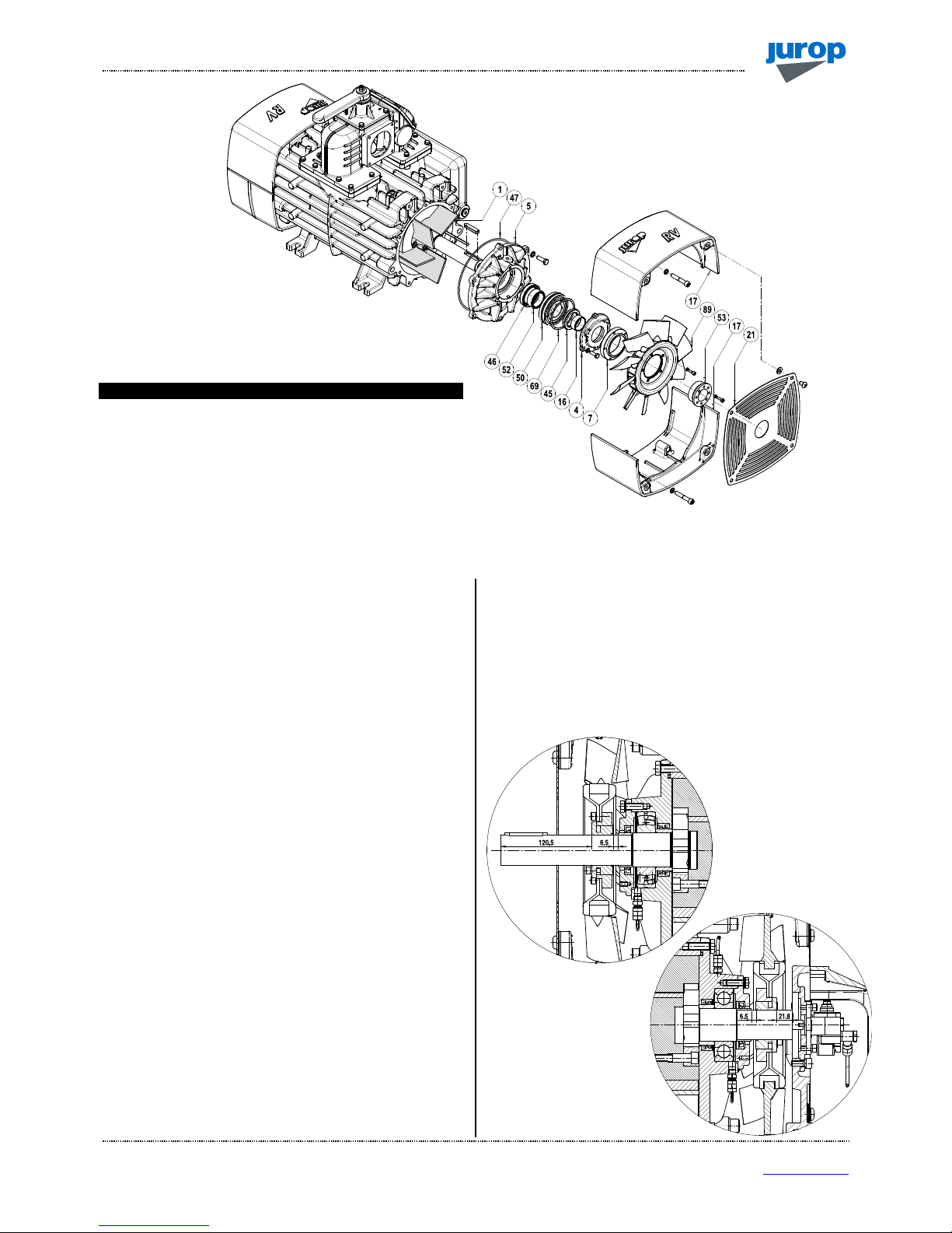
Replacing the vanes
• Remove the vacuum pump from its bearing frame and wash it
before disassembling.
• We recommend that you work on the pump front.
The following drawings refers to RV520. For RV360 see spare part
data sheet drawings at the end of this manual.
• Material that is subject to wear: replace.
C
ORRECT POSITION
I
NCORRETCT POSITION
I
NSTALLATION, USE AND MAINTENANCE MANUAL –
RV360 - 520
REV. 09
21-03-2016
17 / 32
Jurop
SpA
Via Crosera n° 50
33082 Azzano Decimo, PN (Italia)
TEL. +39 0
434 636811
FAX.
+39 0
434 636812
http://www.jurop.it
e-mail: info@jurop.it
Pos.
Code Description Q.ty
1 1601605900 VANE (RV 360) 5
1601606900 VANE (RV 520) 5
16 1626001100 FRONT OIL SEAL BUSHING. 1
35 1680707300 SEAL CAP GASKET 1
45 4022200044 OIL SEAL 65X45X8 1
46 4022200113 ROTOR SEAL 70X55X15 1
47 4022200309 O-RING 4875 1
51 4023130035 BUSHING 55X45X22 1
Pic. 6.8
Disassembling
• Disconnect the drive system, if this is the case, and check
conditions.
• Hydraulic drive: mark the position of the driven shaft on the pump
shaft.
• Remove the conveyor protection (21).
• Remove the aluminium conveyors (17).
• Loosen the 4 screws which blocks the locking set (53) and remove
the cooling fun (89) with the hub (7).
• Remove the seal cap (4). Do not lose compensation ring (69) and
seal cap gasket (35).
• Remove the vacuum pump flange (5) by using the threaded holes
to extract it. Do not lose OR-Ring (47).
• Hold the shaft before extracting the flange: the rotor weight must
not solicit the internal components.
• Extract the worn vanes (1).
• Complete disassembling;
- Extract bearing (50) and seal (46) from the pump flange (5);
- Extract seal (45) from the seal cap (4).
Checking the wear condition
• Check the condition of following parts:
- Seals and gaskets: they may be worn or have been damaged
during disassembling.
- Bushings: we recommend they be replaced if remarkably
scratched.
• A grinder may be needed to cut them for removal. Prevent iron
filings from entering the pump.
• Check whether the seal and the corresponding bushing need to be
replaced also on the pump rear according to their general condition.
Reassembly
• Oil and then insert all vanes in their seats.
• Vacuum pump flange (5): insert seal and bearing if they have been
previously removed or need to be replaced.
• Seal cap (4): insert the new oil seal if replacement has been
needed.
• Bushings on pump axle: new bushings may need to be warmed
before reassembly. Align them properly.
Pic. 6.9
F
RONT FAN
R
EAR FAN
I
NSTALLATION, USE AND MAINTENANCE MANUAL –
RV360 - 520
REV. 0
9
21-03-2016
18 / 32
Jurop
SpA
Via Crosera n° 50
33082 Azzano Decimo, PN (Italia)
TEL. +39 0
434 636811
FAX.
+39 0
434 636812
http://www.jurop.it
e-mail: info@jurop.it
• Reassemble the parts in the following sequence:
- Vacuum pump flange: do not damage the seal while inserting it
on to the axis. Correctly centre and fasten the screws. Properly
align the bearing into its seat.
- Front seal cap: do not damage the seal while inserting it on to the
axis and fasten the screws.
- Fan with docking set.
- Respect the correct distance from the axis head.
- Fasten the 4 screws of the docking set with 10 Nm coupling.
Reassembly the conveyors and their protection.
Do not damage components during assembly by
forcing them exceedingly.
Pic. 6.10
• Do not flip the seal ring during rotation of the shaft. Do not leave
foreign objects inside the pump.
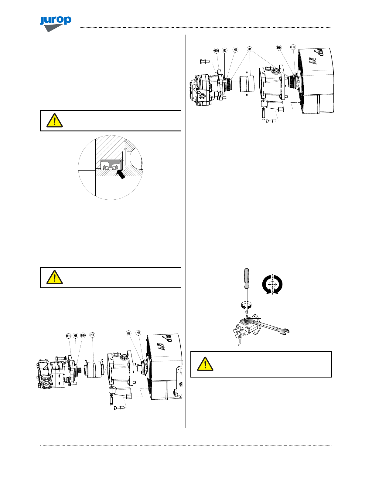
Mounting the hydraulic drive
• We recommend the drive coupling be oiled when vanes are being
replaced. See Pic. 6.11.
• However lubricate the drive coupling every 1500 hours.
We recommend the drive coupling be oiled every
1500 hours.
• Apply coupling hub (H1) to vacuum pump axis respecting the
position marked during disassembly: the grain must go back into the
seat on the rim.
RV 360
RV 520
Pic. 6.11
• Mount the coupling (H1) and lubricate internally with NLGI 2
Lithium grease. Provide an adequate quantity of fat, in order to have a
medium filling.
• Reassembly the motor without forcing onto the seals (H9).
Adjusting the self-lubricating pump
• The automatic lubricating pump is adjusted by the manufacturer
before the shipping.
• If consumption noticeably differs from the indicated value, adjust it
as follows:
- Remove the upper protection cover;
- Using a screwdriver and a 10 mm wrench, adjust the adjusting
screw (K). Close the nut and remount the upper protection cover;
- It is advisable to turn the screw of ¼ of turn and verify the actual
consumption.
Pic. 6.12
Do not reduce oil consumption below the value
indicated in par. 2.3 (for functioning at speeds
different from the maximum, flow is proportionate
to rotating speed).
• ½ turn of the adjusting screw causes a variation in the flow of
approximately 40 - 80 g/h, depending on using conditions.
1/2 giro
40 - 80 g/ h
K
½ giro
40 – 80 g/h

I
NSTALLATION, USE AND MAINTENANCE MANUAL –
RV360 - 520
REV. 09
21-03-2016
19 / 32
Jurop
SpA
Via Crosera n° 50
33082 Azzano Decimo, PN (Italia)
TEL. +39 0
434 636811
FAX.
+39 0
434 636812
http://www.jurop.it
e-mail: info@jurop.it
PROBLEMS
Cause Solution
• Insufficient or absent lubrication
• Verif
y oil and rings. Check oil pump efficiency
• Low tank oil level
• Fill tank with oil
• Excessive rotation speed
• Reduce rpm to the prescribed working speed
• Prolonged functioning at max vacuum rate
• Reduce vacuum rate
• Poor ventilation
• Provide en
ough room around the pump. Verify fan conditions. C
lean fan
protections
•
Vacuum and/or exhaust line of insufficient diameter
• Check dimensioning
Cause Solution
• Broken vanes:
• Clean inner chambers, replace vanes
- due to infiltrated solids
• Check the secondary shutoff and filters of the suction line
and clean
- due to insufficient lubrication
• Check the oil pump
• Power transmission breakdown
• Check and replace the damaged parts
• Ice inside the pump (during the cold season)
• Remove ice and slowly start running it.
Avoid suction of water
Cause Solution
• Four way changeover valve in idle position
• Move the lever to vacuum or pressure mode end stroke
• Four way changeover valve n
ot correctly registered
• Adjust the functioning play and lubricate
• Worn vanes
• Replace vanes
• The non
-
return valve leaks
• Clean or replace if necessary
• Worn seal rings
• Replace
• Tank gate valves or gaskets leak
• Replace damaged or worn parts
• Tank connection pipes leak or are obstructed
• Replace damaged pipes
• Obstructed primary shutoff or suction filter
• Remove and clean
• Encrusted exhaust port
• Remove and clean
• Vacuum line components are too small dimensioned
• Verify dimensions
for pump maximum performances
• Obstructed rubber couplings
• Replace
Cause Solution
• Insufficient or absent lubrication
• Check and adjust the lubricating pump
• Before scrapping the machine, the following materials need to be
separated and suitably disposed of:
• Hydraulic oil.
• Rubber and plastic parts, such as hoses.
• Steel and aluminium parts.
• Recycling materials allow reducing the environmental impact and
respecting the environment.
Do not dispose of in the environment. Dispose of
in compliance with the standards in force.
7. Malfunctions: troubleshooting
Unusual oil consumption
Reduced performances
The vacuum pump does not rotate
8.
Scrapping
The vacuum pump overheats

S
PARE PART DATA SHEET –
RV360
REV. 0
9
21-03-2016
20 / 32
Jurop
SpA
Via Crosera n° 50
33082 Azzano Decimo, PN (Italia)
TEL. +39 0
434 636811
FAX.
+39 0
434 636812
http://www.jurop.it
e-mail: info@jurop.it
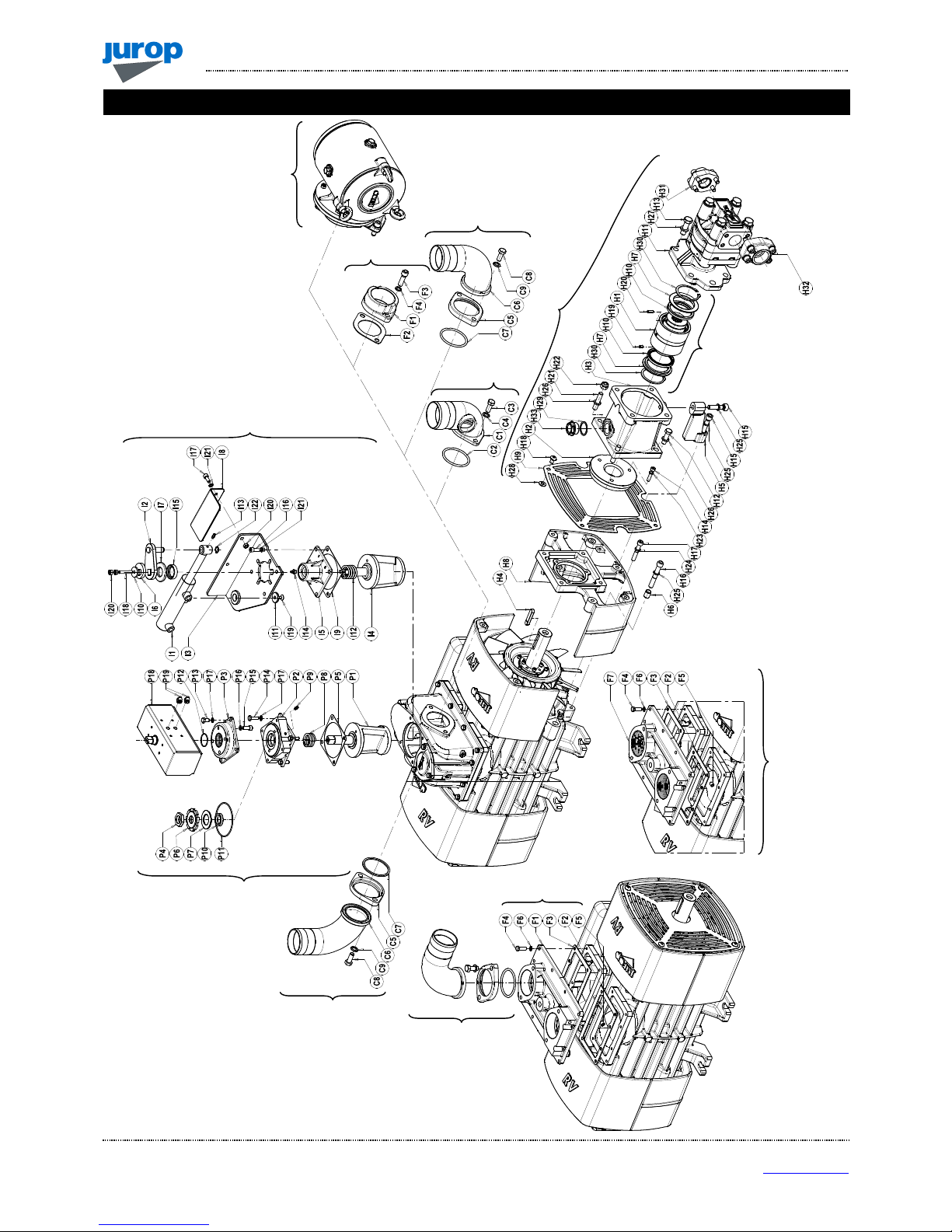
RV 360
IGURE
:
360
ROTATION RIGHT
;
CODE
:
A460809440
360:
A46…
(HOUSING)
(
OIL TANK)
(
OIL PUMP
)

S
PARE PART DATA SHEET –
RV360
REV. 09
21-03-2016
21 / 32
Jurop
SpA
Via Crosera n° 50
33082 Azzano Decimo, PN (Italia)
TEL. +39 0
434 636811
FAX.
+39 0
434 636812
http://www.jurop.it
e-mail: info@jurop.it
RV 360
Pos.
Code Description Q.ty Pos.
Code Description Q.ty
1 1513053300 SIDE MOUNTED OIL TANK SUPPORT 1 45 4022200044 SEAL 65X45X8 2
2 1601605900 RV360 VANE 5 46 4022200113 SEAL 70X55X15 VIT. 2
3 1605500000 COCK HANDLE 1 47 4022200309 OR 4875 VIT. 2
4 1608501700 COCK 1 48 4022300001 NYLON D.6 OIL FILTER 1
5 1610508200 SEAL CAP 2 49 4023100047 BEARING 6309/C3 2
6 1610510800 4-WAY MANIFOLD CAP 1 50 4023130035 BUSHING 55X45X22 2
7 1610513900 RV FLANGE 2 51 4023250501 RUBBER BALL D80 NBR 1
8 16105CF2B0 OIL PUMP FLANGE 1 52 4024251000 2-WAY RH OIL PUMP 1
9 1611001400 RV FAN HUB 2 4024251500 2-WAY LH OIL PUMP 1
10 1621503500 RV360 ROTOR 1 53 4025428111 LOCKING SET RCK16 40X65 2
11 1622002600 OIL PUMP DRIVE 1 54 4026101301 SCREW TE 8,8 M8X20 GALV. 2
11A 4026414617 PLUG 3X40 (FOR RV360 LEFT VERSION) 1 55 4026102806 SCREW TE 8,8 M8X25 GALV. 7
12 1622010200 RV CONVEYOR DOWEL PIN 2 56 4026102807 SCREW TE 8,8 M10X30 GALV. 18
13 1623100000 COCK COVER 1 57 4026102908 SCREW TCEI 8,8 M6X16 GALV. 12
14 1624042800 SPACER 2 58 4026121305 SCREW TCEI 8,8 M6X20 GALV. 2
15 162409YKB0 SPACER 1 59 4026121307 SCREW TCEI 8,8 M8X12 GALV. 10
16 1624202300 COCK REGULATION SPACER 1 60 4026121401 SCREW TCEI 8,8 M8X20 GALV. 2
17 1626001100 SEAL BUSHING 2 61 4026121405 SCREW TCEI 8,8 M12X35 GALV. 3
18 1627105100 RV CONVEYOR 3 62 4026121710 SCREW TCEI 8,8 M12X80 GALV. 2
19 1627105200 RV CONVEYOR WITH SUPPORT 1 63 4026121719 SCREW TCEI 8,8 M10X60 GALV. 2
20 1627505300 MANIFOLD 1 64 4026121815 SCREW TBEI 10,9 M10X15 GALV. 8
21 1642008300 ANTERIOR RV CONVEYOR PROTECTION 1 65 4026122005 SEAL 70X55X15 VIT. 8
22 1642008400 CONVEYOR WITH SUPPORT PROTECTION 1 66 4026135414 SCREW 12,9 M8X45 GALV. 1
23 1642100200 REAR OIL PUMP PROTECTION 1 67 4026135504 SCREW 12,9 M10X10 GALV. 1
24 1650022100 REAR RV SHAFT 1 68 4026155909 SCREW TSPEI 10,9 M12X30 GALV. 2
25 1650022200 ANTERIOR RV SHAFT 1 69 4026300025 COMPENSATION RING LMKAS100C 2
26 16630040E0 PIPE TANK RV360 RH 1 70 4026305508 SELF-LOCKING NUT M12 2
16630041E0 PIPE TANK RV360 LH 1 71 4026308005 NUT M8 GALV. 2
27 1663064300 OIL PUMP – REAR FLANGE OIL LINE RH 1 72 4026350503 WASHER GROWER 6 GALV. 12
1663069900 OIL PUMP – REAR FLANGE OIL LINE LH 1 73 4026350505 WASHER GROWER 8 GALV. 3
28 1663064400 OIL PUMP – ANTERIOR FLANGE RV360 RH 1 74 4026350506 WASHER GROWER 10 GALV. 8
1663065000 OIL PUMP – ANTERIOR FLANGE RV360 LH 1 75 4026350508 WASHER GROWER 12 GALV. 4
29 1663064600 REAR RH/ANTERIOR LH HOUSING OIL LINE 1 76 4026350706 WASHER GROWER 8 FLAT SEC. GALV. 25
1663064800 ANTERIOR RH/REAR LH HOUSING OIL LINE 1 77 4026351506 WASHER M10 GALV. 12
30 1663064800 ANTERIOR RH/REAR LH HOUSING OIL LINE 1 78 4026357003 FLAT WASHER M10 UNI6592 GALV. 2
1663064600 REAR RH/ANTERIOR LH HOUSING OIL LINE 1 79 4026357006 FLAT WASHER M12 UNI6592 GALV. 8
31 1672001600 SPECIAL SCREW TCEI M10X1,5 10 80 4026357007 SCREW 12,9 M8X45 GALV. 2
32 1673001000 OIL FILTER PLUG 1 81 4026426703 RUBBER BAND D.6,5 2
33 1680611400 DISCHARGE SIDE MANIFOLD GASKET 1 82 4026501006 TAB 12X8X56 1
34 1680611500 SUCTION SIDE MANIFOLD GASKET 1 83 4026702000 UNIV. DIR. CONNECTION 4XG1/8 4
35 1680611600 MANIFOLD CAP GASKET 1 84 4026706000 UNIV. 90° CONNECTION 4XG1/8 2
36 1680700200 COCK COVER GASKET 1 85 4026706003 UNIV. 90° CONNECTION 6XG1/8 2
37 1680707300 SEAL CAP GASKET 2 86 4026706101 TURNING CONNECTION 4XG1/8 2
38 1685002800 WASHER 30X8,5X4 ZINC. 1 87 4026904503 PLUG M20X1,5 1
39 1685100300 WASHER D20 2 88 4026910103 PLUG G1 1
40 1685100800 WASHER 8X14X1,5 COPPER 2 89 4028360000 FRONT FAN (FOR RV360 RIGHT VERSION) 1
41 1687509300 RV360 HOUSING 1 4028360001 FRONT FAN (FOR RV360 LEFT VERSION) 1
42 1687600000 OIL TANK 1 90 4028360001 REAR FAN (FOR RV360 RIGHT VERSION) 1
43 1691000000 COCK SPRING 1 4028360000 REAR FAN (FOR RV360 LEFT VERSION) 1
44 4022200030 SEAL 41X27X10 GP NBR 1
1892005900 KIT GASKET RV360 1
1892006400 KIT ANTERIOR SHAFT RV360-520 1
1892006500 KIT REAR SHAFT RV360-520 1
S
PARE PART DATA SHEET –
RV360 A
CCESSORIES
REV. 0
9
21-03-2016
22 / 32
Jurop
SpA
Via Crosera n° 50
33082 Azzano Decimo, PN (Italia)
TEL. +39 0
434 636811
FAX.
+39 0
434 636812
http://www.jurop.it
e-mail: info@jurop.it
3
8
7
6
3
3
11
5
4
1
-2
10
9
RV 360 - A
CCESSORIES

S
PARE PART DATA SHEET –
RV360 - A
CCESSORIES
REV. 09
21-03-2016
23 / 32
Jurop
SpA
Via Crosera n° 50
33082 Azzano Decimo, PN (Italia)
TEL. +39 0
434 636811
FAX.
+39 0
434 636812
http://www.jurop.it
e-mail: info@jurop.it
RV 360 Accessories
Pos.
Code Description Q.ty Pos.
Code Description Q.ty
1 1852108600 FIXED SUCTION CONVEYOR Ø80 KIT 9 143028B7B0 PNEUMAT. OPERATED 4-WAY VALVE KIT
C1 1627100300 SUCTION CONVEYOR Ø80 1 P1 160858KNB0 PNEUMATIC ACTUATOR COCK 1
C2 4022200307 OR 6287 VIT. 1 P2 161258B4B0 PNEUMATIC ACTUATOR SUPPORT 1
C3 4026103002 SCREW TE M12X30 UNI5739 GALV. 2 P3 1640580QB0 PNEUMATIC ACTUATOR COVER 1
C4 4026350709 WASHER GROWER 12 FLAT SEC. GALV. 2 P4 167007ZAB0 PNEUMATIC ACTUATOR NUT 1
2 1852108900 FIXED SUCTION CONVEYOR Ø76 KIT P5 1680700200 COVER GASKET 1
C1 1627100200 SUCTION COVEYOR Ø76 1 P6 168409PQB0 COCK REGULATION FERRULE 1
C2 4022200307 OR 6287 VIT. 1 P7 168529TFB0 COCK REGULATION SPACER 1
C3 4026103002 SCREW TE M12X30 UNI5739 GALV. 2 P8 1691000200 COCK SPRING 1
C4 4026350709 WASHER GROWER 12 FLAT SEC. GALV. 2 P9 4022100100 SPHERICAL GREASER M6X1 1
3 1852109000 TURNING CONVEYOR Ø76 KIT P10 4022200005 SEAL 37X27X7 1
C5 1610100000 CONVEYOR FLANGE 1 P11 4022200330 OR 3375 1
C6 1627100500 CONVEYOR Ø76 1 P12 4022200331 OR 2137 1
C7 4022200307 OR 6287 VIT. 1 P13 4026102804 SCREW TE M8X16 UNI5739 ZINC. 4
C8 4026103002 SCREW TE M12X30 UNI5739 GALV. 2 P14 4026102807 SCREW TE M8X25 UNI5739 ZINC. 4
C9 4026350709 WASHER GROWER 12 FLAT. SEC. GALV. 2 P15 4026121405 SCREW TCEI M8X20 UNI5931 ZINC. 4
4 1852111600 FLANGE 2” ½ NPT KIT P16 4026350505 WASHER GROWER 8 GALV. 4
F1 1610101400 FLANGE 2” ½ NPT 1 P17 4026351505 WASHER M8 ZINC. 8
F2 1680614500 MANIFOLD GASKET 1 P18 4027100405 PNEUMATIC ACTUATOR 1
F3 4026121711 SCREW TCEI 8,8 M12X40 GALV. 2 P19 4027421206 CONNECTION R15 6XG1/8 2
F4 4026350508 WASHER GROWER 12 GALV. 2 10 HYDRAULIC DRIVE
5 18521CNGB0 SUCTION FILTER KIT H1 1470106700 HDR RV COUPLING 1
6 FLANGED MANIFOLD H2 1610052300 HDR RV FLANGE COUPLING 1
F1 1627505500 FLANGED MANIFOLD 1 H3 1612501000 HDR MOTOR MOUNTING FLANGE 1
F2 1680611400 DISCHARGE SIDE MANIFOLD GASKET 1 H4 1617015500 TAB RV360-520 HDR 1
F3 1680611500 SUCTION SIDE MANIFOLD GASKET 1 H5 16171001E0 SQUARE HDR 1
F4 4026102807 SCREW TE 8,8 M8X25 UNI5931 GALV. 12 H6 1622010200 RV CONVEYOR DOWEL PIN 4
F5 4026135504 SCREW 12,9 M10X10 GALV. 1 H7 1624042300 HDR RV COUPLING SEAL SPACER 2
F6 4026350706 WASHER GROWER 8 FLAT SEC. GALV. 12 H8 1627105200 RV CONVEYOR WITH SUPPORT 2
7 THREADED MANIFOLD H9 1642008400 CONVEYOR WITH SUPPORT PROTECTION 2
F2 1680611400 DISCHARGE SIDE MANIFOLD GASKET 1 H10 4022200011 SEAL A 64X80X8 NBR 2
F3 1680611500 SUCTION SIDE MANIFOLD GASKET 1 H11 4024107009 RV360 HYDRAULIC MOTOR 1
F4 4026102807 SCREW TE 8,8 M8X25 GALV. 12 H12 4026103004 SCREW TE 8,8 M12X40 UNI5739 GALV. 4
F5 4026135504 SCREW 12,9 M10X10 GALV. 1 H13 4026103111 SCREW TE 8,8 M14X45 GALV. 4
F6 4026350706 WASHER GROWER 8 GALV. 12 H14 4026121409 SCREW TCEI 8,8 M8X40 UNI5931 GALV. 3
F7 1627505600 THREADED MANIFOLD 1 H15 4026121713 SCREW TCEI 8,8 M12X80 UNI5931 GALV. 2
8 143029K2B0 KIT HYDRAULIC ACTUATOR H16 4026121719 SCREW TCEI 8,8 M10X60 UNI5931 GALV. 4
I1 143027T6B0 CILINDER 1 H17 4026121815 SCREW TBEI 10,9 M10X15 GALV. 8
I2 150206XXB0 LEVER 1 H18 4026122005 SCREW 12,9 M8X12 8
I3 151309JVB0 BASE 1 H19 4026136005 SCREW 12,9 M8X20 1
I4 1608503200 MANIFOLD 1 H20 4026136009 SCREW TCEI 8,8 M8X40 UNI5931 GALV. 1
I5 1623100800 COVER 1 H21 4026171203 SCREW 8,8 M12X40 GALV. 2
I6 16240A0IB0 SPACER 1 H22 4026305508 SELF-LOCKING NUT M12 4
I7 1624202300 SPACER 1 H23 4026350505 WASHER GROWER 8 GALV. 6
I8 164206XYB0 ACTUATOR PROTECTION 1 H24 4026350506 WASHER GROWER 10 GALV. 8
I9 1680700200 GASKET 1 H25 4026350508 WASHER GROWER 12 GALV. 8
I10 1685002800 WASHER FE 30X8,5 SP.4 GALV. 1 H26 4026350709 WASHER GROWER 12 FLAT SEC. GALV. 4
I11 168509U0B0 WASHER 1 H27 4026350710 WASHER GROWER 14 FLAT SEC. GALV. 4
I12 1691000000 SPRING 1 H28 4026357006 FLAT WASHER M10 GALV. 8
I13 4022100100 GREASER M6X1 1 H29 4026359001 WASHER 40X33,5X1,5 1
I14 4022100107 GREASER 45 1 H30 4026510040 SEEGER E63 UNI7435-30 2
I15 4022200030 SEAL 41X27X10 1 H31 4026711003 SAE G1’’1/4 FLANGE 1
I16 4026120405 SCREW TCEI M8X25 4 H32 4026711004 SAE G1’’1/2 FLANGE 1
I17 4026121405 SCREW TCEI M8X20 GALV. 2 H33 4026904003 PLUG G1 GALV. 1
I18 4026135414 SCREW M8X45 ZINC. 1 11 1892006300 COMPLETE JOINT KIT RV HDR 1
I19 4026155705 SCREW TSPEI M8X16 GALV. 1
I20 4026308005 NUT M8 ESAG.GALV. 4
I21 4026350505 WASHER GROWER 8 GALV. 6
I22 4026510012 SEEGER E14 1
S
PARE PART DATA SHEET –
RV520
REV. 0
6
21-03-2016
24 / 32
Jurop
SpA
Via Crosera n° 50
33082 Azzano Decimo, PN (Italia)
TEL. +39 0
434 636811
FAX.
+39 0
434 636812
http://www.jurop.it
e-mail: info@jurop.it
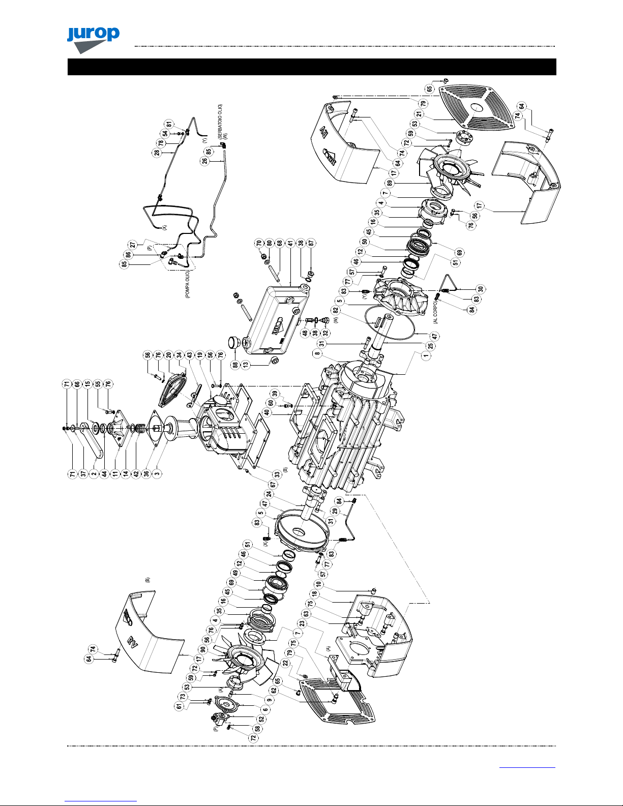
RV 520
F
IGURE
:
RV
520
ROTATION RIGHT
;
CODE
:
A470809440
RV
520:
A47…

S
PARE PART DATA SHEET –
RV520
REV. 09
21-03-2016
25 / 32
Jurop
SpA
Via Crosera n° 50
33082 Azzano Decimo, PN (Italia)
TEL. +39 0
434 636811
FAX.
+39 0
434 636812
http://www.jurop.it
e-mail: info@jurop.it
RV 520
Pos.
Code Description Q.ty Pos.
Code Description Q.ty
1 1601606900 RV520 VANE 5 47 4022200309 OR 4875 VIT. 2
2 1605500100 COCK HANDLE 1 48 4022300001 NYLON D.6 OIL FILTER 1
3 1608502500 COCK 1 49 4023100047 BEARING 6309/C3 1
4 1610508200 SEAL CAP 2 50 4023105008 BEARING 21309 E/C3 1
5 1610513900 RV FLANGE 2 51 4023130035 BUSHING 55X45X22 2
6 16105CF2B0 OIL PUMP FLANGE 1 52 4024251000 2-WAY RH OIL PUMP 1
7 1611001400 RV FAN HUB 2 4024251500 2-WAY LH OIL PUMP 1
8 1621507900 RV520 ROTOR 1 53 4025428111 LOCKING SET RCK16 40X65 2
9 1622002600 OIL PUMP DRIVE 1 54 4026101301 SCREW TE 8,8 M 6X10 GALV. 2
10 1622010200 RV CONVEYOR DOWEL PIN 2 55 4026102806 SCREW TE 8,8 M8X20 GALV. 7
11 1623100500 COCK COVER 1 56 4026102807 SCREW TE 8,8 M8X25 GALV. 18
12 1624042100 RV520 DISTANCE RING 2 57 4026102908 SCREW TE 8,8 M10X30 GALV. 12
13 1624042800 SPACER 2 58 4026121305 SCREW TCEI 8,8 M6X16 GALV. 2
14 162409YKB0 SPACER 1 59 4026121307 SCREW TCEI 8,8 M6X20 GALV. 10
15 1624202300 COCK REGULATION SPACER 1 60 4026121401 SCREW TCEI 8,8 M8X12 GALV. 2
16 1626001100 SEAL BUSHING 2 61 4026121405 SCREW TCEI 8,8 M8X20 GALV. 3
17 1627105100 RV CONVEYOR 3 62 4026121710 SCREW TCEI 8,8 M12X35 Z GALV.INC. 2
18 1627105200 RV CONVEYOR WITH SUPPORT 1 63 4026121719 SCREW TCEI 8,8 M12X80 GALV. 4
19 16275007E0 MANIFOLD 1 64 4026121815 SCREW TCEI 8,8 M10X60 GALV. 6
20 16401008E0 COVER 1 65 4026122005 SCREW TBEI 10,9 M10X15 GALV. 8
21 1642008300 ANTERIOR RV CONVEYOR PROTECTION 1 66 4026135414 SCREW 12,9 M8X45 GALV. 1
22 1642008400 CONVEYOR WITH SUPPORT PROTECTION 1 67 4026135504 SCREW 12,9 M10X10 GALV. 1
23 1642100200 REAR OIL PUMP PROTECTION 1 68 4026171211 SCREW STUD 8,8 M12X80 2
24 1650022100 REAR RV SHAFT 1 69 4026300025 COMPENSATION RING LMKAS100C 2
25 1650022200 ANTERIOR RV SHAFT 1 70 4026305508 SELF-LOCKING NUT M12 2
26 16630050E0 PIPE TANK RV520 RH 1 71 4026308005 NUT M8 GALV. 2
16630051E0 PIPE TANK RV520 LH 1 72 4026350503 WASHER GROWER 6 GALV. 12
27 1663064300 OIL PUMP – REAR FLANGE OIL LINE DH 1 73 4026350505 WASHER GROWER 8 GALV. 3
1663069900 OIL PUMP – REAR FLANGE OIL LINE SH 1 74 4026350506 WASHER GROWER 10 GALV. 6
28 1663064500 OIL PUMP – ANTERIOR FLANGE RV520 RH 1 75 4026350508 WASHER GROWER 12 GALV. 6
1663065100 OIL PUMP – ANTERIOR FLANGE RV520 LH 1 76 4026350706 WASHER GROWER 8 FLAT SEC. GALV. 25
29 1663064700 REAR RH/ANTERIOR LH HOUSING OIL LINE 1 77 4026351506 WASHER M10 GALV. 12
1663064900 ANTERIOR RH/REAR LH HOUSING OIL LINE 1 78 4026357003 FLAT WASHER M6 GALV. 2
30 1663064900 ANTERIOR RH/REAR LH HOUSING OIL LINE 1 79 4026357006 FLAT WASHER M10 GALV. 8
1663064700 REAR RH/ANTERIOR LH HOUSING OIL LINE 1 80 4026357007 FLAT WASHER M12 GALV. 2
31 1672001600 SPECIAL SCREW TCEI M10X1,5 10 81 4026426703 RUBBER BAND D.6,5 2
32 1673001000 OIL FILTER PLUG 1 82 4026501006 TAB 12X8X56 1
33 1680610200 MANIFOLD GASKET 2 83 4026702000 UNIV. DIR. CONNECTION 4XG1/8 4
34 16807011E0 MANIFOLD CAP GASKET 1 84 4026706000 UNIV. 90° CONNECTION 4XG1/8 2
35 1680707300 SEAL CAP GASKET 2 85 4026706003 UNIV. 90° CONNECTION 6XG1/8 2
36 1680707800 COCK COVER GASKET 1 86 4026706101 TURNING CONNECTION 4XG1/8 2
37 1685002800 WASHER 30X8,5 GALV. 1 87 4026904503 PLUG M20X1,5 1
38 1685100300 WASHER D20 2 88 4026910103 PLUG G1 1
39 1685100800 WASHER 8X14X1,5 COPPER 2 89 4028360000 FRONT FAN (FOR RV520 RIGHT VERSION) 1
40 1687509400 RV520 HOUSING 1 4028360001 FRONT FAN (FOR RV520 LEFT VERSION) 1
41 1687600000 OIL TANK 1 90 4028360001 REAR FAN (FOR RV520 RIGHT VERSION) 1
42 1691000000 COCK SPRING 1 4028360000 REAR FAN (FOR RV520 LEFT VERSION) 1
43 18930008E0 CLAPET 1
44 4022200030 SEAL 41X27X10 GP NBR 1 1892006000 KIT GASKET RV 520 1
45 4022200044 SEAL 65X45X8 2 1892006400 KIT SHAFT ANTERIEUR RV 360-520 1
46 4022200113 SEAL 70X55X15 VIT. 2 1892006500 KIT REAR SHAFT RV 360-520 1

REV. 0
9
21-03-2016
S
PARE PART DATA SHEET –
RV520 - A
CCESSORIES
26 / 32
Jurop
SpA
Via Crosera n° 50
33082 Azzano Decimo, PN (Italia)
TEL. +39 0
434 636811
FAX.
+39 0
434 636812
http://www.jurop.it
e-mail: info@jurop.it
RV 520 - A
CCESSORIES
9
7
3
-4
3
-4
1
-2
3
-4
3
-4
6
13
8
11
12
10

S
PARE PART DATA SHEET –
RV520 - A
CCESSORIES
REV. 09
21-03-2016
27 / 32
Jurop
SpA
Via Crosera n° 50
33082 Azzano Decimo, PN (Italia)
TEL. +39 0
434 636811
FAX.
+39 0
434 636812
http://www.jurop.it
e-mail: info@jurop.it
RV 520 Accessories
Pos.
Code Description Q.ty Pos.
Code Description Q.ty
1 1852103400 FIXED SUCTION CONVEYOR Ø80 KIT 10 143028GZB0 PNEUM. OPERATED 4-WAY VALVE KIT
C1 1627101300 SUCTION CONVEYOR Ø80 1 P1 160858KBB0 PNEUMATIC ACTUATOR COCK 1
C2 4022200310 OR 6362 VIT. 1 P2 161258H0B0 PNEUMATIC ACTUATOR SUPPORT 1
C3 4026102807 SCREW TE M8X25 GALV. 4 P3 1640580QB0 PNEUMATIC ACTUATOR COVER 1
C4 4026350706 WASHER GROWER 8 FLAT SEC. GALV. 4 P4 167007ZAB0 PNEUMATIC ACTUATOR NUT 1
P5 1680707800 COVER GASKET 1
2 1852103500 FIXED SUCTION CONVEYOR Ø100 KIT P6 168409PQB0 COCK REGULATION FERRULE 1
C1 1627101200 SUCTION CONVEYOR Ø100 1 P7 168529TFB0 COCK REGULATION SPACER 1
C2 4022200310 OR 6362 VIT. 1 P8 1691000200 COCK SPRING 1
C3 4026102807 SCREW TE M8X25 GALV. 4 P9 4022100100 SPHERICAL GREASER M6X1 1
C4 4026350706 WASHER GROWER 8 FLAT SEC. GALV. 4 P10 4022200005 SEAL 37X27X7 1
P11 4022200330 OR 3375 1
3 1852103900 TURNING CONVEYOR Ø80 KIT P12 4022200331 OR 2137 1
C5 1610101100 CONVEYOR FLANGE 1 P13 4026102804 SCREW TE M8X16 UNI5739 GALV. 4
C6 1627102700 CONVEYOR Ø80 1 P14 4026102807 SCREW TE M8X25 UNI5739 GALV. 4
C7 4022200310 OR 6362 VIT. 1 P15 4026121405 SCREW TCEI M8X20 UNI5931 GALV. 4
C8 4026102808 SCREW TE M8X30 UNI5739 GALV. 4 P16 4026350505 WASHER GROWER 8 GALV. 4
C9 4026350706 WASHER GROWER 8 FLAT SEC. GALV. 4 P17 4026351505 WASHER M8 ZINC. 8
P18 4027100405 PNEUMATIC ACTUATOR 1
4 1852104000 TURNING CONVEYOR Ø100 KIT P19 4027421206 CONNECTION R15 6XG1/8 2
C5 1610101100 CONVEYOR FLANGE 1
C6 1627102400 CONVEYOR Ø100 1 11 143029KRB0 KIT HYDRAULIC ACTUATOR
C7 4022200310 OR 6362 VIT. 1 I1 143027T6B0 CILINDER 1
C8 4026102808 SCREW TE M8X30 UNI5739 GALV. 4 I2 15020A10B0 LEVER 1
C9 4026350706 WASHER GROWER 8 FLAT SEC. GALV. 4 I3 1513007TJB0 BASE 1
I4 1608502900 MANIFOLD 1
5 1852104100 KIT FOR SAFETY VALVE I5 1623100700 COVER 1
S1 1627102500 SAFETY VALVE G2 SUPPORT 1 I6 162409YKB0 SPACER 1
S2 4022200310 OR 6362 VIT. 1 I7 1624043400 SPACER 1
S3 4026102807 SCREW TE 8,8 M8X25 UNI5739 GALV. 4 I8 1624202300 SPACER 1
S4 4026102810 SCREW TE 8,8 M8X40 UNI5739 GALV. 4 I9 164206XYB0 ACTUATOR PROTECTION 1
S5 4026308005 NUT M8 UNI5588 GALV. 4 I10 1673009700 GREASER LINK 1
S6 4026350706 WASHER GROWER 8 FLAT SEC. GALV. 8 I11 1680707800 GASKET 1
I12 1685002800 WASHER 30X8,5 GALV. 1
6 1852111700 FLANGE 3” NPT KIT I13 168509U0B0 WASHER 1
F1 1610101500 FLANGE 3” NPT 1 I14 1691000000 SPRING 1
F2 1680709900 MANIFOLD GASKET 1 I15 4022100100 GREASER M6X1 1
F3 4026102808 SCREW TCEI 8,8 M8X30 GALV. 4 I16 4022100107 GREASER 45ø M10X1 1
F4 4026350706 WASHER GROWER 8 GALV. 4 I17 4022200030 SEAL 41X27X10 1
I18 4026121408 SCREW TCEI M8X25 4
7 185212L4B0 SUCTION FILTER KIT COMPONENTS I19 4026121405 SCREW TCEI M8X20 GALV. 2
I20 4026135414 SCREW M8X45 1
8 FLANGED MANIFOLD I21 4026155705 SCREW TSPEI M8X16 1
F1 1627504800 FLANGED MANIFOLD 1 I22 4026308005 NUT M8 HEXAG. GALV. 4
F2 1680610200 MANIFOLD GASKET 2 I23 4026350505 WASHER GROWER 8 GALV. 6
F3 4026135504 SCREW 12,9 M10X10 GALV. 1 I24 4026510012 ELASTIC SEAL E14 1
F4 4026350706 WAHER GROWER 8 FLAT SEC. GALV. 12
F5 4026102807 SCREW TE 8,8 M8X25 UNI5931 GALV. 12
9 THREADED MANIFOLD
F2 1680610200 MANIFOLD GASKET 2
F3 4026135504 SCREW 12,9 M10X10 GALV. 1
F4 4026350706 WASHER GROWER 8 FLAT SEC. GALV. 12
F5 4026102807 SCREW TE 8,8 M8X25 UNI5931 GALV. 12
F6 1627504900 THREADED MANIFOLD 1

REV. 0
9
21-03-2016
S
PARE PART DATA SHEET –
RV520 - A
CCESSORIES
28 / 32
Jurop
SpA
Via Crosera n° 50
33082 Azzano Decimo, PN (Italia)
TEL. +39 0
434 636811
FAX.
+39 0
434 636812
http://www.jurop.it
e-mail: info@jurop.it
Pos.
Code Description Q.ty Pos.
Code Description Q.ty
12 HYDRAULIC DRIVE H17 4026121815 SCREW TCEI 8,8 M10X60 GALV. 6
H1 1470106700 HDR RV COUPLING 1 H18 4026122005 SCREW TBEI 10,9 M10X15 GALV. 8
H2 1610052300 HDR RV FLANGE COUPLING 1 H19 4026136005 SCREW 12,9 M8X12 1
H3 1612501000 HDR MOTOR MOUNTING FLANGE 1 H20 4026136009 SCREW 12,9 M8X20 1
H4 1617015500 TAB RV360-520 HDR 1 H21 4026171203 SCREW 8,8 M12X40 GALV. 2
H5 16171001E0 SQUARE HDR 1 H22 4026305508 SELF-LOCKING NUT M12 4
H6 1622010200 RV CONVEYOR DOWEL PIN 4 H23 4026350505 WASHER GROWER 8 GALV. 6
H7 1624042300 HDR RV COUPLING SEAL SPACER 2 H24 4026350506 WASHER GROWER 10 GALV. 6
H8 1627105200 RV CONVEYOR WITH SUPPORT 2 H25 4026350508 WASHER GROWER 12 GALV. 10
H9 1642008400 CONVEYOR WITH SUPPORT PROTECTION 2 H26 4026350709 WASHER GROWER 12 GALV. 4
H10 4022200011 SEAL A 64X80X8 NBR 2 H27 4026350710 WASHER GROWER 14 GALV. 4
H11 4024107001 RV520 HYDRAULIC MOTOR 1 H28 4026357006 FLAT WASHER M10 UNI6592 GALV. 8
H12 4026103004 SCREW TE 8,8 M12X40 GALV. 2 H29 4026359001 WASHER 40X33,5X1,5 1
H13 4026103111 SCREW TE 8,8 M14X45 GALV. 4 H30 4026510040 SEEGER E63 UNI7435-30 2
H14 4026121409 SCREW TCEI 8,8 M8X40 GALV. 3 H31 4026904003 PLUG G1 GALV. 1
H15 4026121713 SCREW TCEI 8,8 M12X50 GALV. 2
H16 4026121719 SCREW TCEI 8,8 M12X80 GALV. 6 13 1892006300 COMPLETE JOINT KIT RV HDR 1

C
OOLING FANS INSTALLATION INSTRUCTIONS
REV. 09
21-03-2016
29 / 32
Jurop
SpA
Via Crosera n° 50
33082 Azzano Decimo, PN (Italia)
TEL. +39 0
434 636811
FAX.
+39 0
434 636812
http://www.jurop.it
e-mail: info@jurop.it
Material
Code Description
4025428111 4 SCREW LOCKING COLLAR
4028360000 CLOCKWISE ROTATION FAN
4028360001 COUNTER CLOCKWISE ROTATION FAN
1611001400 FAN HUB
4046850012 THREAD-LOCKER MEDIUM RESISTANCE LOCTITE 243 (*)
(*):10 cc tube available upon request.
Before installation
• Clean all the components: remove dirt and particles that can
prevent a correct assembly.
• Prepare the locking element:
- Align bushing keys.
- Apply medium resistance thread-locker on the locking screw
threads. Pour on the thread evenly.
- Fasten the 4 screws and leave them loose by at least 2 full turns.
• Do not use the threaded holes that can be seen on the locking
collar front. These are used for the disassemble.
Do not use the threaded holes that can be seen
on the locking collar front. These are used for the
disassemble.
Pic. 9.1
E: Threaded holes for disassembly
• Install the steel hub and the fan by means of the 5 screws and
washers.
• Apply medium resistance thread-locker on the locking screw
threads. Pour on the thread evenly.
• Fasten the screws following a cross shake pattern.
• Check the screw fastening twice to be sure they have been evenly
tightened.
Pic. 9.2
Pic. 9.3
Installation
• Insert the locking collar inside the fan hub as shown in pictures below,
until in touch with the fan hub.
Pic. 9.4
Pic. 9.5
• Install pre assembled fan on the shaft.
• Be careful to respect the suggested distance of 9 mm in between
the fan hub and the end of stroke on the shaft.
Respect the suggested distance of 9 mm in
between the fan hub and the end of stroke on the
shaft.
• Use a spacer to keep the suggested distance.
9.
C
OOLING FANS INSTALLATION INSTRUCTIONS
STRINGERE
VITI A CROCE
E
EE
E
F
ASTEN THE
S
CREWS
F
AN FRONT
R
EAR FAN
L
OCKING ELEMENT IN
POSITION INSIDE FAN HUB

C
OOLING FANS INSTALLATION INSTRUCTIONS
REV. 0
9
21-03-2016
30 / 32
Jurop
SpA
Via Crosera n° 50
33082 Azzano Decimo, PN (Italia)
TEL. +39 0
434 636811
FAX.
+39 0
434 636812
http://www.jurop.it
e-mail: info@jurop.it
1
2
3
4
• Bring in position, and keep the locking element in touch with the
fun hub.
Pic. 9.6
• Use just 4 screws with Torque=17Nm:
1° time: Tighten the 4 screws on the locking collar
(Torque=17Nm) Fasten them following a cross shaped pattern;
2° time: Lower the torque to 16Nm and fasten the screws
again, always following a cross-shaped pattern.
3° time: If necessary, check one last time the screws
(Torque=16Nm) to be sure that they have been tightened evenly.
Pic. 9.7
Disassemble
• Remove the 4 screws that keep the locking collar in place (Pic.
9.8).
• If possible, use an impulse screwdriver.
• Heat the hub with if the screws are stuck because of dirt, rust or if
thread locking glue has been used.
• Once the two parts of the locking collar separate, it’s possible to
remove the fan from the shaft.
• If needed, insert a flat head screwdriver in the crack, to help the
removal.
Heat the hub with if the screws are stuck because
of dirt, rust or if thread locking glue has been
used.
Pic. 9.8
S
CREWS IN THE
EXTRACTION HOLES
E
NLARGE THE SLOT FOR EASY
DISASSEMBLE
F
AN FRONT
R
EAR FAN

REV. 09
21-03-2016
31 / 32
Jurop
SpA
Via Crosera n° 50
33082 Azzano Decimo, PN (Italia)
TEL. +39 0
434 636811
FAX.
+39 0
434 636812
http://www.jurop.it
e-mail: info@jurop.it

REV. 08
21-05-2015
32 / 32
Jurop
SpA
Via Crosera n° 50
33082 Azzano Decimo, PN (Italia)
TEL. +39 0
434 636811
FAX.
+39 0
434 636812
http://www.jurop.it
e-mail: info@jurop.it
Model Issue date Revision No. Revision date Filled out by Viewed by
RV 360 - 520 10-09-2013 09 21-03-2016 U.T. A.T.
Jurop SpA
Via Crosera, 50
33082 Azzano Decimo, PN (ITALY)
Tel. +39 0434 636811
Fax. +39 0434 636812
http://www.jurop.it
e-mail: info@jurop.it
Jurop SpA reserves the right to modify the products described in this manual without prior notice.
 Loading...