


Model JI-820
Incremental Encoder Emulator
User Manual
Jupiter Instruments
JI-820
Version 1.1
5/20/2018 Edition
1
5/18/18

Jupiter Instruments
TABLE OF CONTENTS
_____________________________________________________________________________________
1. INTRODUCTION 4
2. BLOCK DIAGRAM 5
2.0 JI-820 Block Diagram 5
3. FRONT AND REAR PANELS 6
3.0 Front Panel 6
3.0.1
D-Sub Connector Signals 7
3.1 Rear Panel 8
4. SOFTWARE INSTALATION 9
4.1 Software Installation 9
4.1.1
USB Driver Installation 9
4.1.2
Control Software Installation 10
4.2 Software Check 10
5. JI-820 CONTROL APPLICATION 13
5.0 Main Window 13
5.1 Setup Menu 15
6. SYSTEM EXERCISE 17
6.0 Encoder Emulation 17
APPENDIX A 23
1.0 JI-820 Specifications 23
APPENDIX B 26
1.0 Specifications: Incremental Encoder Example 26
APPENDIX C 27
1. Minimum PC System Requirements 27
APPENDIX D 28
1.0 General Information 28
1.1 Warranty 28
JI-820
2
2/18/18

Jupiter Instruments
_____________________________________________________________________________________
1.2 Thirty-Day Return Policy 28
1.3 Limitation of Liability 28
1.4 Contact Us 28
JI-820
3
2/18/18

Jupiter Instruments
1. INTRODUCTION
The JI-820 is a flexible, easy-to-use, PC controlled instrument designed to precisely emulate the
function of a wide variety of incremental encoders. It provides the design, system, or test engineer
with a tool to accurately emulate encoder signals generated by motion control and industrial
monitoring systems. Variable encoder parameter available to the user include cycles per revolution,
cycle frequency, A/B signal phase, Z signal position and polarity, signal amplitude, and selectable
signal interface. An intuitive Windows application manages instrument setup and control.
Communications and unit power is all provided via a USB 2.0 connection.
Features
_____________________________________________________________________________________
• Emulates/Simulates Rotary, Linear, and Quadrature Encoders
• Programmable Pulse-Per-Rev: 4 to 4,000,000
• Adjustable Cycle Frequency: 0.1 Hz to 5.0 MHz (50 nS steps)
• Variable A/B Phase: 10° to 170° in 1° steps (90° nominal)
• Index (Z) Signal: Selectable Polarity (+/- pulse) and Position (+/- 1 cycle)
• Variable Signal (A, B, Z) Amplitude: Internal - 5.0 to 18.0 Volts (100 mV steps)
External - 5.0 to 30.0 Volts
• Output Interface: RS-422, Open-Drain, Push-Pull, or Push-Pull Complementary
• Instrument Setup and Control via an intuitive Windows Application GUI
• Unit power and communications via USB 2.0. No external power-supply required.
JI-820
4
2/18/18

Jupiter Instruments
_____________________________________________________________________________________
2. BLOCK DIAGRAM
USB
Connector
2.0 JI-820 Block Diagram
USB PHY
D-sub, 9-Pin
uP
DAC
FPGA
INT
PWR
EXT
Ext. Voltage
A
/A
B
/B
Z
/Z
GND
GND
Activity
LED
Status
LED
Figure 2.1 JI-820 Block Diagram
JI-820
5
2/18/18

Jupiter Instruments
_____________________________________________________________________________________
3. FRONT AND REAR PANELS
3.0 Front Panel
Description and location of Front Panel Connector and LEDs is shown below.
31
2
1. Power – Power-on LED (Green). Also indicates JI-820 device has been
enumerated.
2. D-Sub Connector: 9-Pin, Female Socket, (AMP L77SDE09SA4CH4R)
Suggested Mating Connector (AMP DE09P065H TXLF)
3. Output – Output signals (A, B, Z) are enabled (Amber)
JI-820
6
2/18/18

Jupiter Instruments
_____________________________________________________________________________________
3.0.1 D-Sub Connector Signals
9-Pin, Female, D-Sub Connector
Pin # Direction Signal Name Description
1 Input Ext. Voltage
External Encoder Voltage (Optional)
Voltage Range: 5.0 to 30.0V
2 Output Z Z (Index) Encoder Signal
3 Output A A Encoder Signal
4 Output B B Encoder Signal
5 - GND GND – signal return
6 - GND GND – signal return
7 Output /Z Inverted Z (Index) Encoder Signal
8 Output /A Inverted A Encoder Signal
9 Output /B Inverted B Encoder Signal
JI-820
7
2/18/18

Jupiter Instruments
_____________________________________________________________________________________
3.1 Rear Panel
Rear Panel shown below.
1. USB Connector: Type ‘B’, (Molex 67068-0000)
Suggested USB Cable (Molex 88732-9200)
JI-820
8
2/18/18

Jupiter Instruments
_____________________________________________________________________________________
4. SOFTWARE INSTALATION
4.1 Software Installation
A USB driver as well as JI-820 Control software will be installed on the host PC. Step-by-step
installation instructions are as follows:
4.1.1 USB Driver Installation
a. Host PC with an Internet Connection
b. Host PC without Internet Connection
1. Ensure the host PC is connected to the internet.
2. Connect the JI-820 to a spare USB port on the PC.
3. Windows will silently connect to the Windows Update website and install the
required driver(s). In some cases, this could take several minutes to complete.
4. At installation conclusion, verify that the front panel Power LED is on.
Note: If the drivers were not automatically found or the JI-820 device has
not been added, continue to the “Host PC without internet Connection” step
below.
5. Driver installation is now complete.
1. Insert the JI-820 USB Flash Drive (included with your JI-820 purchase) into a
spare USB port on the host PC.
2. Using Windows Explorer, find the FTDI CDN driver installation program
(CDM21228_Setup.exe) on the flash drive. Double click on the file to begin
installation.
3. Follow the on screen instructions until the installation is complete.
4. Driver installation is now complete.
JI-820
9
2/18/18

Jupiter Instruments
4.1.2 Control Software Installation
_____________________________________________________________________________________
1. Insert the JI-820 USB Flash Drive (included with your JI-820 purchase) into a spare
USB port on the host PC (or download the latest JI-820 Control Application
from
http://www.jupiteri.com/JI-820/JI-820_Ver1.2a.zip to a temporary location on
your PC.)
2. Using Windows Explorer, find the file “setup.exe” on the CD drive. Double click on the
file to begin installation.
3. Follow the on screen instructions until the installation is complete.
4. Control installation is now complete.
4.2 Software Check
1. Using the USB cable that was included with your purchase, connect the JI-820 unit to a USB
port on the host PC.
2. Verify that the front panel Power LED (green) is on.
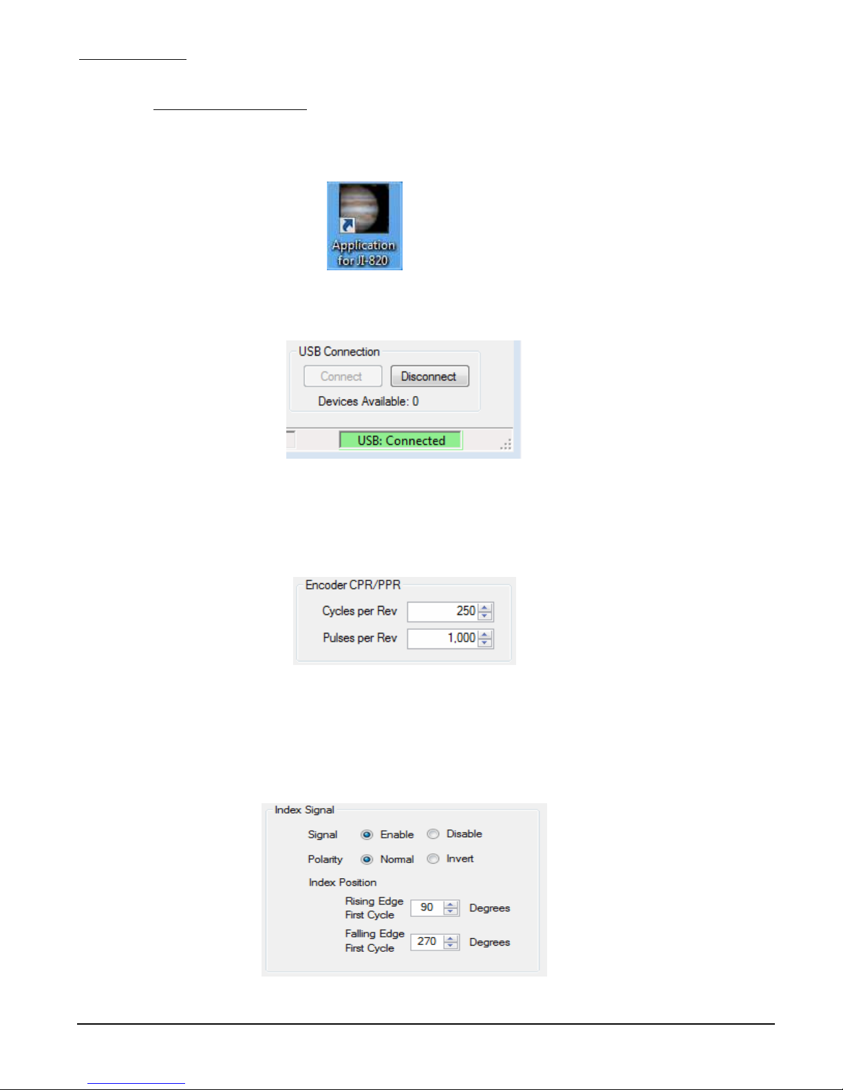
3. Launch the JI-820 application by clicking the JI-820 icon.
4. Verify that the application main window is displayed as shown in figure 4.3-1
JI-820
10
2/18/18

Jupiter Instruments
5. At the main window, verify that a JI-820 device is available then open the USB port by clicking
the Connect button at the bottom right corner of pane.
_____________________________________________________________________________________
Figure 4.3-1 JI-820 Control Application Main Window
JI-820
11
2/18/18
Jupiter Instruments
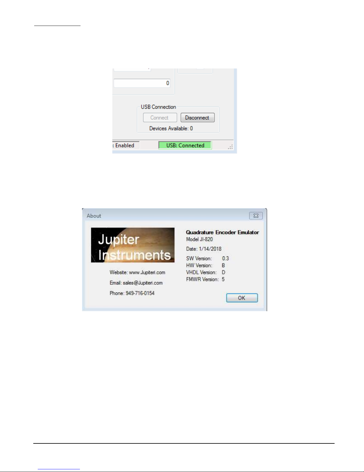
6. Verify a USB connection by confirming a USB: Connected port status.
_____________________________________________________________________________________
.
7. At the menu bar, open the About message box by clicking Help then About.
8. Verify that the version numbers for the HW Version and FW Version are valid (i.e. HW
Version: A, VHDL Version: 3, etc.) If a question mark (HW Version: ?, or VHDL Version: ?) or
some other character appears, an error has occurred.
Figure 4.3-2 JI-820 About Window
9. If no errors have occurred (or if errors have been resolved) the Software Check is complete.
JI-820
12
2/18/18

Jupiter Instruments
_____________________________________________________________________________________
5. JI-820 CONTROL APPLICATION
5.0 Main Window
The JI-820 Control Application Main Window is shown in figure 5.0-1.
JI-820
Figure 5.0-1. JI-820 Control Application Main Window
1. Encoder Rate – Quadrature encoder rate is entered as a Cycle Frequency, Cycle Period,
or RPM. Maximum and minimum limits are listed for each parameter. Note that the signal
phase resolution setting will affect maximum and minimum limits as well as the parameter
resolution.
2. Mode – The behavior of the encoder is selected as either Free Run or Pulse Move. The
Free Run mode provides continuous, endless operation of the encoder. The Run button
starts operation and the Stop button halts operation. The Pulse Move mode control the
transmission of I2C messages. The Run button initiates a session where by I2C messages
stored in the message list are squelchy executed. The session starts at the cursor position
and ends either by the execution of the lasted message in the list or by clicking the Stop
button.
3. Rotation Direction – The encoder can operate in either the clock-wise (CW) or counter-
clock-wise (CCW) direction.
4. Operation – This group of controls provides:
13
2/18/18

Jupiter Instruments
5. Output Signal – Output signal (A, B, Z) control (On/Off).
6. Encoder Position – The current position of the encoder is displayed both numerically and
7. Signal State – The current state of the output signals (A, B, Z) is displayed here.
8. USB Connection – Connected/Disconnected a JI-820 device to the application.
_____________________________________________________________________________________
a. Signal Single-Stepping in either the clock-wise (Single-Step CW) or counter-clock-
wise (Single-Step CCW) direction. If the Step on Z check box is selected and the Z
signal (index) is enabled, Single-Step will also step on each Z signal transition.
b. Reset Position – Clicking this button resets the encoder position:
1. Revolutions = 0
2. Cycle = 1
3. Phase = 1 (A = 0, B = 0)
4. Pulse Count = 0
c. Run – Clicking this button starts either a Free Run or Pulse Move operation.
d. Stop – Clicking this button halts either a Free Run or Pulse Move operation.
visually (Rotary Position)
JI-820
14
2/18/18

Jupiter Instruments
_____________________________________________________________________________________
5.1 Setup Menu
Encoder parameters such as Cycles-Per-Revolution (or Pulses-Per-Revolution), Index Signal,
and encoder voltage are entered at the Setup Menu. The Setup Menu is shown below in figure
5.1-1. To access the Setup menu, click Setup followed by Setup Menu at the Main Window
menu bar.
1. Encoder CPR/PPR – The encoder Cycles-Per-Revolution (CPR) or Pulses-Per-
Revolution (PPR) parameter is entered here.
2. Phase Setting – The 4 phases that comprise a single cycle of an ideal encoder are equally
spaced at exactly 90 degrees. Settings or adjustments other than 90 degrees can be applied
to all 4 phases via the Phase Setting control. The coarseness of the setting (90, 45, 10, 5, 1
degrees) is selected using the Phase Resolution control. Note that Phase Resolution
settings will affect maximum and minimum limits of Cycle Frequency, Cycle Period, and
RPM.
3. Index Signal – This group of controls provides:
a. Index Signal Enable/Disable
b. Index Single Polarity – Normal or Inverted.
c. Index Single Position – Position is adjusted relative to Phase 1 of the first cycle
and is displayed in the signal timing diagram. Note that Phase Resolution settings
will affect the coarseness of the setting.
JI-820
Figure 5.1-1 JI-820 Control Application Setup Menu
15
2/18/18

Jupiter Instruments
.
4. Output Signal – This group of controls provides:
5. Signal Timing – This is a visual representation in time of all 3 encoder signals (A,B,Z)
_____________________________________________________________________________________
a. Voltage Source – The voltage source to drive the encoder signals is selected as
either Internal or External. The Internal voltage range is from 5.0V to 18.0V,
adjustable in 100 mV increments. The External voltage is applied to pin-1 of the 9pin D-Sub connector and has a voltage range from 5.0V to 30.0V.
b. Output Drive – The encoder signal drive type is selected as either Push-Pull or
Open-Drain.
c. Changes to parameters in this group can be updated immediately if the Immediate
Update check box is checked. For example, changes in A, B, and Z signal
amplitude can be observed in real-time using Immediate Update.
JI-820
16
2/18/18

Jupiter Instruments
_____________________________________________________________________________________
6. SYSTEM EXERCISE
6.0 Encoder Emulation
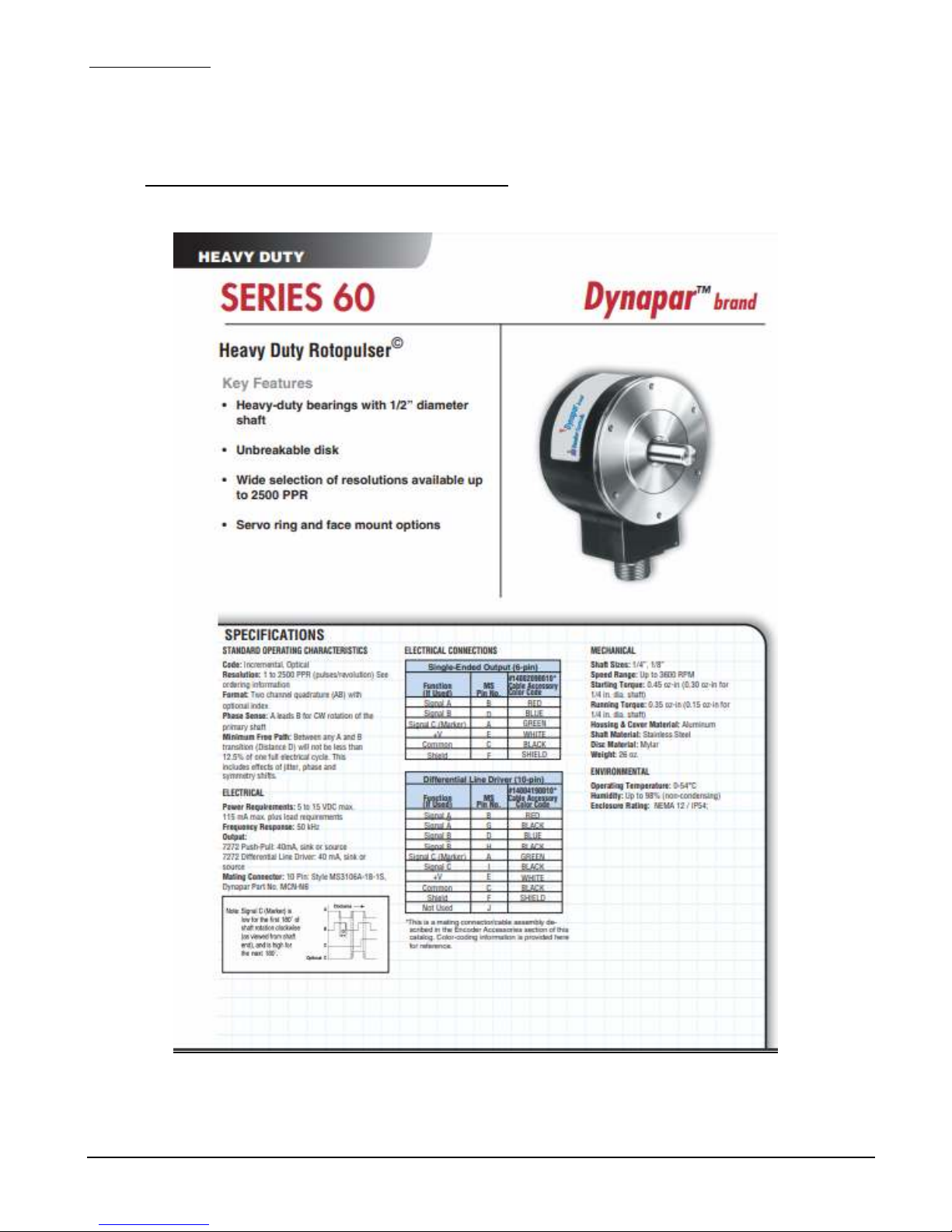
This exercise will demonstrate how to configure and emulate the behavior of an incremental
encoder. As an example, we will emulate a Dynapar Series 60 Incremental Encoder (PN:
63AAEF1000AB, Appendix B). Electrical specifications:
Equipment needed for this exercise:
A. Equipment Setup
Connect the equipment as follows:
• Voltage: 5V to 15V
• Output: Single-Ended, Push-Pull
• Pulses/Rev: 1000
• Option: Marker (Z Index)
• Maximum Frequency: 50 KHz
• Minimum Free Path: 12.5% (jitter, phase, and symmetry shifts)
1. JI-820 unit
2. 4-channel oscilloscope
3. Break-out connector for 9-pin D-sub.
4. PC/Laptop loaded with JI-820 Control Application software
1. Connect 9-pin D-sub break-out connector to 9-pin D-sub on JI-820.
2. Connect oscilloscope channel 1 to D-sub break-out connector pin-3 (signal A).
3. Connect oscilloscope channel 2 to D-sub break-out connector pin-4 (signal B).
4. Connect oscilloscope channel 3 to D-sub break-out connector pin-2 (signal Z).
5. Connect oscilloscope channel RTNs to D-sub break-out connector pins- 5 & 6 (GND).
6. Set amplitude for all three oscilloscope channels to 10V/div.
7. Set sweep speed to 50us/div.
8. Set trigger to Normal, Rising-Edge, Channel 3.
9. Finally, using the supplied USB cable, connect the JI-820 to a spare USB port on the PC.
TBD
JI-820
Figure 6.0-1 Test Setup
17
2/18/18
Jupiter Instruments
B. Encoder Configuration
At the PC:
_____________________________________________________________________________________
1. Launch the application by double clicking on the JI-820 icon.
2. At the main window, verify that a JI-820 device is available then open the USB port
by clicking the Connect button at the bottom right corner of pane.
3. Next, open the Setup menu by click Setup followed by Setup Menu at the Main
Window menu bar. The Setup Menu opens (see Figure 5.1-1)
4. At the Encoder CPR/PPR group box, set the Pulses per Rev to 1000.
5. At the Index Signal group box, set
• Signal: Enable
• Polarity: Normal
• Index position:
• Rising Edge, First Cycle: 90 degrees
• Rising Edge, First Cycle: 270 degrees
JI-820
18
2/18/18

Jupiter Instruments
_____________________________________________________________________________________
6. At the Output Signal group box, set
• Voltage: 12.0V
• Voltage Source: Internal
• Output Drive: Push-Pull
7. Save the encoder configuration by clicking the Save button at the bottom right
corner of the pane.
C. Encoder Operation
At the PC:
1. At the main window, set the Cycle Frequency to 10K Hz. Cycle Frequency is found
in the Encoder Rate group box.
2. At the Output Signals group box, enable the output signals A, B, and Z.
JI-820
3. Finally, start encoder operation by clicking run in the Operations group box.
19
2/18/18

Jupiter Instruments
_____________________________________________________________________________________
4. Verify the following waveform on the oscilloscope.
5. At the oscilloscope, increase the sweep speed to 20uS/div. Verify the following
waveform on the oscilloscope.
6. At the main window, change encoder rotation direction from CW to CCW by
JI-820
selecting CCW in the Rotation Direction group box.
20
2/18/18

Jupiter Instruments
_____________________________________________________________________________________
7. At the oscilloscope, verify the following waveform. Note that the phase sequence
has changed from 1,2,3,4 to 4,3,2,1.
JI-820
21
2/18/18

Jupiter Instruments
_____________________________________________________________________________________
8. While running, experiment with the encoder behavior and configuration by making
changes to:
• Cycle Frequency
• Z Signal
• Polarity
• Rising/Fall Edge positions
• Signal Amplitude
9. Encoder emulation exercise is now complete.
JI-820
22
2/18/18

Jupiter Instruments
_____________________________________________________________________________________
APPENDIX A
1.0 JI-820 Specifications
Incremental Encoder Emulator
Model JI-820
Electrical Specifications
General
Signals
Cycles per Revolution (CPR)
Pulses per Revolution (PPR)
Signal Phase Resolution
Frequency Range, Cycle
Position Tracking:
Revolutions -231 to 231
Cycle -231 to 231
Phase 1 to 4
A, /A, B, /B, Z, /Z
Programmable: 1 to 1,00,000
Programmable: 4 to 4,00,000
Selectable: 1, 5, 10, 45, or 90 degrees
Phase Resolution Freq. Max. Freq. Min. Resolution
90 5.00 MHz 10.0 Hz 50 nS
45 2.50 MHz 5.00 Hz 100 nS
10 555 KHz 1.11 Hz 450 nS
5 277 KHz 0.55 Hz 900 nS
1 55.5 KHz 0.11 Hz 4500 nS
Jupiter Instruments
Ver 1.2
1/21/2018 Edition
JI-820
Operational Modes
Index Signal (Z)
Position Programmable: +/- 1 cycle span (max)
Polarity Selectable: Positive or Negative Pulse
Output
Type
Free Run, Single-Step, Pulse Move
Selectable: RS-422
Open-Drain
Push-Pull
Push-Pull Complementary
Internal or External
23
2/18/18

Jupiter Instruments
_____________________________________________________________________________________
Voltage Source
Internal
Voltage
Current
Adjustable 5.0V to 18.0V (100mV increments)
Sink: 100 mA (max per signal)
Source: 30 mA max per signal (90 mA combined)
External
Voltage
Current
5.0V to 30.0V
Sink/Source: 100 mA (max per signal)
Short-Circuit
Protection
Output Control
Internal and External
Enable/Disable Output
Connector:
Type Standard 9-Pin, D-sub, Female
Pin-outs Pin 1 = External Voltage (Input)
Pin 2 = Z
Pin 3 = A
Pin 4 = B
Pin 5 = GND
Pin 6 = GND
Pin 7 = /Z
Pin 8 = /A
Pin 9 = /B
LEDs
Power
Activity
PC Interface
Communication
Connector Standard type B socket
Power
Power-On
Output Signal Activity
USB 2.0 Full Speed
USB supplied
Current Draw: 270mA (Nominal)
690mA (Maximum @ max. signal load)
JI-820
24
2/18/18

Jupiter Instruments
Mechanical and Environmental Specifications
_____________________________________________________________________________________
Mechanical
Dimension
Weight
Construction
Environmental
Operating Temp
Storage Temp
3.3" x 1.1" x 5.0" (WxHxL)
0.2lbs
Extruded Aluminum Enclosure
0C to 45C
-20C to 70C
JI-820
25
2/18/18
Jupiter Instruments
APPENDIX B
1.0 Specifications: Incremental Encoder Example
_____________________________________________________________________________________
JI-820
26
2/18/18

Jupiter Instruments
APPENDIX C
1. Minimum PC System Requirements
_____________________________________________________________________________________
• Microsoft Windows 7/8/10
• Pentium 4 or equivalent processor (600 M minimum)
• USB 2.0 port
• 50 MB Free hard disk space
• 256 MB Memory
• (Internet Connection Preferred)
JI-820
27
2/18/18

Jupiter Instruments
_____________________________________________________________________________________
APPENDIX D
1.0 General Information
1.1 Warranty
The equipment is warranted for one year from data of purchase against defects in materials or
workmanship. Jupiter Instruments reserves the right to repair or replace products at its own and
complete discretion. Customer must obtain from Jupiter Instruments a Return Authorization Number
(RMA) prior to returning any products to Jupiter Instruments. Products returned under this Warranty
must be unmodified and in original packaging. Jupiter Instruments reserves the right to refuse
warranty repairs or replacements for any products that are damaged or not in original form.
The customer is responsible for the shipping and insurance cost arising from the return of products
to Jupiter Instruments. Jupiter Instruments will return all in-warranty products with shipping cost
prepaid.
1.2 Thirty-Day Return Policy
Customers may return Jupiter Instruments products for a full refund if Jupiter Instruments is
contacted within thirty days of the customer’s receipt of the product. Customer may return Jupiter
Instruments products for credit, exchange, or a refund. Customer must obtain form Jupiter
Instruments a Return Authorization Number (RMA) prior to returning any products to Jupiter
Instruments. Products must be returned unmodified and in original packaging. Jupiter Instruments
reserves the right to refuse return rights for any products that are damaged or not in original form.
Volume orders may be subject to a significant restocking fee.
1.3 Limitation of Liability
Jupiter Instruments’ liability shall be limited to the repair or replacement of defective products in
accordance with the Jupiter Instruments limited warranty.
Jupiter Instruments shall not be liable for any incidental, special or consequential damages for
breach of any warranty, expressed or implied, directly or indirectly arising out of Jupiter Instruments’
sale of merchandise, including any failure to deliver any merchandise, or arising out of customer's
installation or use, whether proper or improper, of the product, separately or in combination with
other equipment, or from any other cause. Use all Jupiter Instruments products and accessories at
your own risk.
Products sold by Jupiter Instruments are not authorized for use as critical components in life
support devices or systems.
1.4 Contact Us
• Address: Jupiter Instruments
Mission Viejo, CA 92692
• Email:
Sales@Jupiteri.com
Tech@Jupiteri.com
• Phone: Sales and Information: (949)-716-0154
• Website
www.Jupiteri.com
JI-820
28
2/18/18
 Loading...