

Page 1
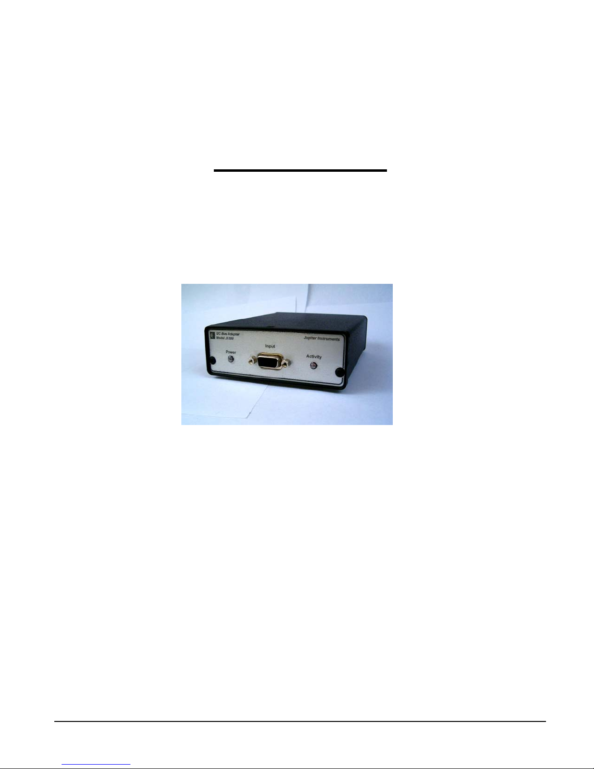
Model JI-300
I2C Host Adapter
User’s Manual
Jupiter Instruments 9/1/2008 Edition
JI-300
1
4/5/07
Version 1.4
Page 2

Jupiter Instruments_____________________________________________________________________________________
TABLE OF CONTENTS
1. INTRODUCTION 4
1.1 Front Panel Description 5
1.2 Rear Panel Description 5
2. GETTING STARTED 6
2.1 Software Installation 6
2.2 Hardware Setup 6
2.3 Communications Check 6
2.4 I2C Tx/Rx Session 7
3. EEPROM PROGRAMMING UTILITY 10
3.1 EEPROM Programming Session 10
4. MAIN WINDOW AND MENU DESCRIPTIONS 13
4.1 Main Window 13
4.2 Setup Menu 14
4.3 Add/Edit I2C Message Window - Read 15
4.4 Add/Edit I2C Message Window - Write 16
4.5 EEPROM Programming Utility window 17
APPENDIX A 19
1.0 Specifications 19
APPENDIX B 21
1.0 PC System Requirements 21
APPENDIX C 22
1. Installing USB Driver 22
2.0 Installing Application Software 25
APPENDIX D 26
JI-300
2
9/9/07
Page 3

Jupiter Instruments_____________________________________________________________________________________
1.0 General Information 26
1.1 Warranty 26
1.2 Thirty-Day Return Policy 26
1.3 Limitation of Liability 26
1.4 Contact Us 26
JI-300
3
9/9/07
Page 4

Jupiter Instruments_____________________________________________________________________________________
1. INTRODUCTION
The JI-300 is a versatile, easy to use, PC hosted adapter used to drive I2C communications
to/from a target bus. The desktop unit can be configured to interface a variety of I2C networks.
Bus parameters such as clock frequency, duty-cycle, setup and hold times, bus voltage, and pullup resistor values can be varied. JI-300’s diagnostic features including “excessive clock-stretch”,
“bus-not-free”, and “bus contention” monitoring, as well as status reporting at the conclusion of
each message transaction simplifies I2C trouble-shooting. A Windows software application
manages the setup and control of the instrument. Communications and unit power is provided via
a USB 2.0 connection.
Features
• Programmable SCL clock frequency from 255Hz to 3.8Mhz (20nS steps).
• Variable bus voltage from 1.50V to 5.25V (10mV steps).
• Supports Master and multi-Master operation.
• Software selectable bus pull-up resistors (16 values including open)
• Low I2C bus capacitance (<40pF typ.)
• USB 2.0 host interface
• Switched target bus voltage available at connector
• Easy to use Graphical User Interface (GUI) software.
• Create custom software applications by way of either direct or
Virtual COM Port (VCP) drivers. Programming requires no
knowledge of USB!
• Includes everything needed to get started – I2C Adapter unit, I2C cable, USB cable,
and a CD-ROM containing application software and user’s manual.
Applications
• Firmware debugging and hardware troubleshooting
• Production line testing
• Equipment repair and diagnostics
in-depth
JI-300
4
9/9/07
Page 5
Jupiter Instruments_____________________________________________________________________________________
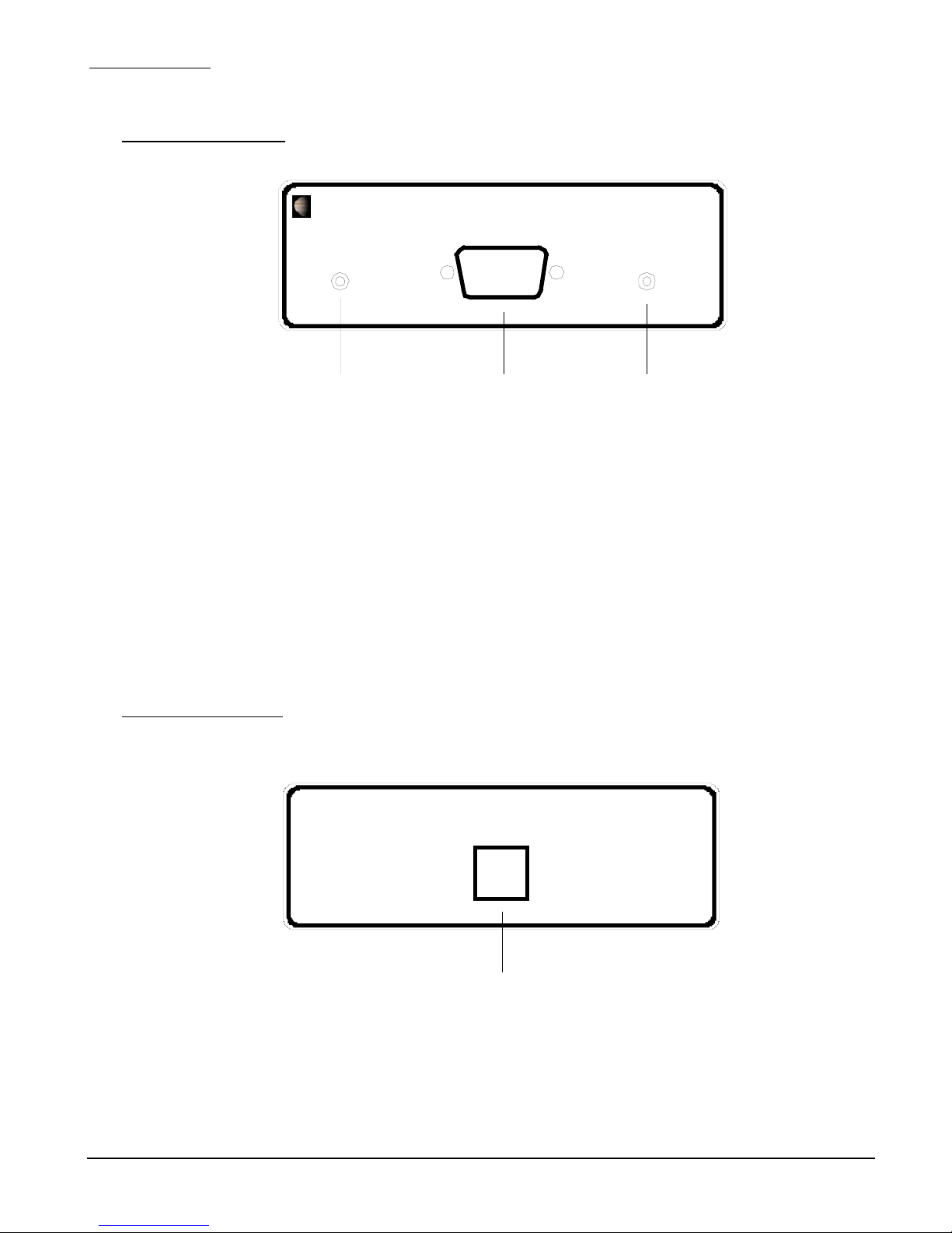
1.1 Front Panel Description
1. Power – Power on LED
2. Activity – I2C bus activity/USB port open LED.
3. Input – I2C probe cable jack. 9-pin, Female, D-Sub connector (AMP 745781-4)
Pin 5 = GND
Pin 6 = SCL
Pin 8 = Vbus
Pin 2, 3, 4, 7, 9 = No Connection
I2C Bus Monotor Model JI-210
I2C Bus Adapter Jupiter Instruments
Ju pit er I ns tr um e nt s
Mod el J I -3 00
Input
Power Activity
1 2 3
Pin-outs: Pin 1 = SDA
1.2 Rear Panel Description
1. USB – Type ‘B’ connector (Molex 67068-0000)
I2C Bus M onotor Mode l JI-210
Jupite r Instrume nts
USB
1
JI-300
5
9/9/07
Page 6
Jupiter Instruments_____________________________________________________________________________________
2. GETTING STARTED
2.1 Software Installation
The JI-300 Host Adapter requires the installation of both a USB driver and application software.
The drivers must be installed on the host PC’s hard-drive. The application software, however, can
be installed locally or executed directly from CD-ROM. See appendix C for detailed instructions on
installing both the USB driver and JI-300 application software.
2.2 Hardware Setup
Note that USB drivers for the JI-300 must be installed before the Hardware Setup will run
successfully.
1. Connect the I2C Host Adapter unit to the host PC using 6’ USB cable.
2. After a few seconds, confirm that the JI-300 is powered by verifying that the front panel PWR
LED is on.
2.3 Communications Check
1. Ensure that the I2C Host Adapter unit is connected to the host PC and power is on.
2. Go to the folder C:/JI300/
3. Launch the I2C Host Adapter application by clicking I2C_Bus_Adapter.exe.
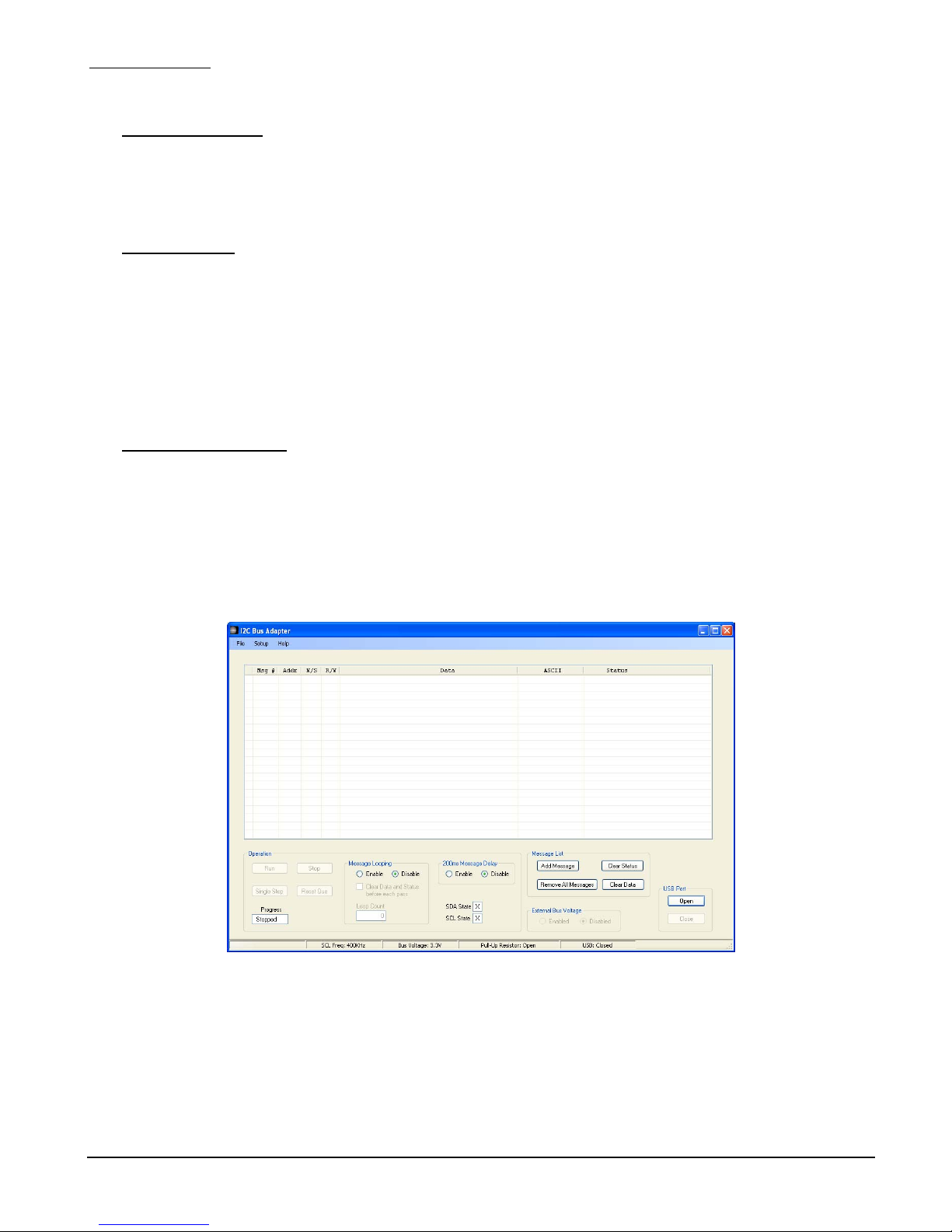
4. Verify that the main I2C Host Adapter window is displayed as shown in figure 1.
Figure 1. I2C Host Adapter Main Window
If an error occurs and the window does not appear, begin by verifying that the .NET
Framework is installed. To do this, click Start on your windows desktop, select Control Panel,
and then double-click the Add or Remove Programs icon. When the window appears, scroll
through the list of applications. If you see the .NET Framework 3.0 listed, the latest version is
JI-300
6
9/9/07
Page 7
Jupiter Instruments_____________________________________________________________________________________
installed. If not listed, go to http://msdn2.microsoft.com/en-us/netframework/aa569263.aspx for
instructions on downloading and installing the .NET Framework.
5. At the main window, open a USB port by clicking the Open button in the USB Connection
group.
6. Ensure an open USB port by confirming an open port status.
7. At the menu bar, open the About message box by selecting Help then About.
8. Verify that the version numbers for the HW Version x.x and VHDL Version x.x are valid (i.e.
1.0, 2.1, etc.) If a question mark (?) or some other character appears, an error has occurred.
9. If no errors have occurred (or if errors have been resolved) the Communications Check has
passed.
2.4 I2C Tx/Rx Session
For this exercise, a target slave device (included with the JI-300 kit) or I2C network with at least
one slave device will be needed. Device power (or network) can be supplied by either the I2C
target or JI-300 Adapter. The following steps are for use with the test M24C04 I2C target device.
1. Ensure that the I2C Host Adapter unit is connected and power is on. (Section 2.2 Hardware
Setup)
2. Ensure that the I2C Host Adapter application is running and the USB port is open. (Section 2.3
Communications Check)
3. Connect the I2C probe cable to the D-sub connector on the I2C Host Adapter front panel.
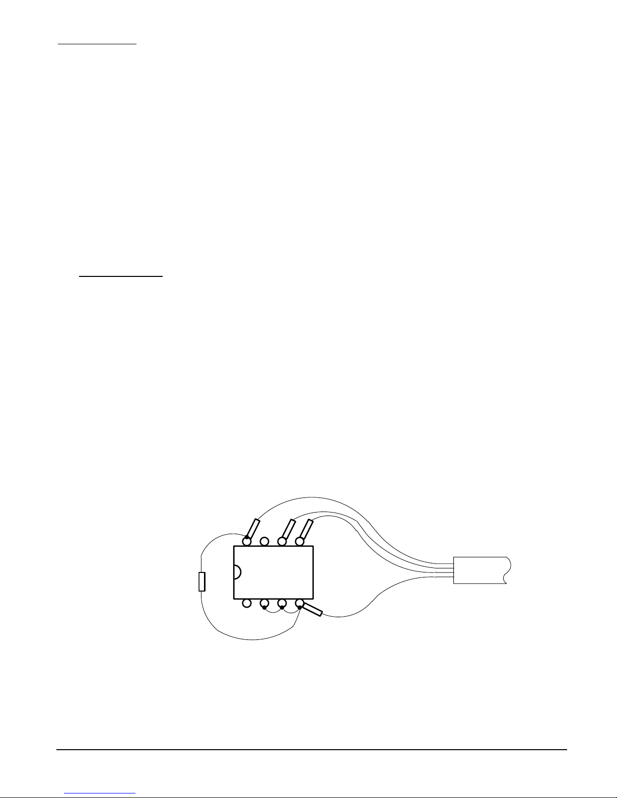
4. Locate the test M24C04 I2C (4Kbit Serial I2C EEPROM) target device supplied with the kit.
(See Figure 2)
5. Connect the four I2C bus probes (SDA, SCL, PWR, and GND) to the I2C target device. (See
Figure 2)
PWR
VCC
SCL
SDA
SDAWCn SCL
C1
0.1uF
25V
Figure 2. Connections to M24C04 I2C target test device
6. At the main window, click the Add Message button to begin adding I2C messages to the list.
JI-300
MC24C04
NC E2E1 VSS
I2C Probe Cable
GND
7
9/9/07
Page 8
Jupiter Instruments_____________________________________________________________________________________
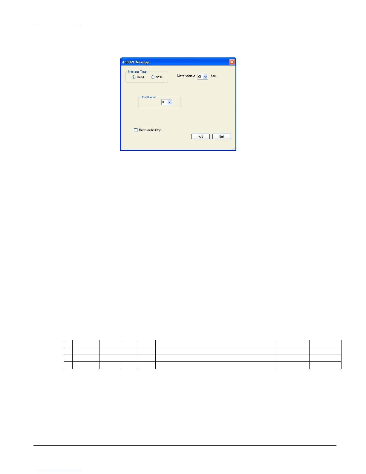
7. The Add I2C Message window is now displayed. (See Figure 3)
Figure 3. Add I2C Message Window
8. Add the following data to create a write message:
1. Message Type: Write (Note: The Message Window will change from a Read
to Write when the Write Message Type is selected)
2. Slave Address: A0h
3. Write Data (1): 00
4. Remove the Stop: Check Box
9. Click Add to add the message to the message list.
10. Next, add a read message.
11. Add the following data to create a read message:
1. Message Type: Read
2. Slave Address: A1h
3. Read Count: 16
4. Remove the Stop: un-Check Box
12. Click Add to add the message to the message list, followed by Exit.
13. Verify that two messages (a read and write) have been added to the Message List.
(See figure 4)
MSG # Addr N/S R/W Data ASCII Status
001 A0 * W 10
002 A1 R
XX XX XX XX XX XX XX XX XX XX XX XX XX XX XX XX
14. At the Main Window menu bar, open the setup menu by selecting Setup, then Setup Menu.
JI-300
Figure 4. I2C Messages
8
9/9/07
Page 9
Jupiter Instruments_____________________________________________________________________________________
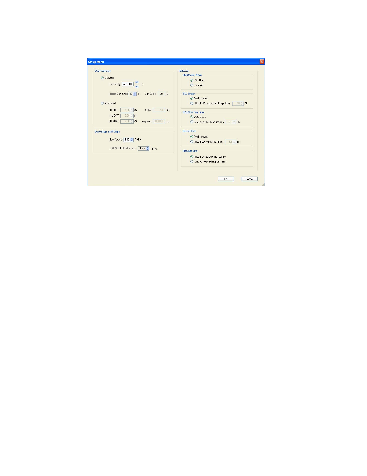
15. The Setup menu is now displayed (See Figure 5)
Figure 5. Setup Menu
16. At the Bus Voltage group, select a 1K ohm bus pull-up resistor by clicking the up/down buttons.
17. Click OK to save the selection and close the Setup Window.
18. At the main window, turn-on the external bus voltage by clicking Enable in the External Bus
Voltage group.
19. Enable Message Looping by clicking Enable in the Message Looping group.
20. Now, begin an I2C session by clicking Reset Que, followed by clicking Run in the Operation
group.
21. Verify the following actions:
1. The message “Success!” is in the status columns for both messages.
2. The text “Hello world!” is in the ASCII column of the read message.
3. The asterisk cursor quickly moving back-and-forth between the two messages.
22. The I2C Tx/Rx exercise is now complete.
JI-300
9
9/9/07
Page 10

Jupiter Instruments_____________________________________________________________________________________
3. EEPROM PROGRAMMING UTILITY
This fully integrated utility is designed for programming a variety of EEPROM and memory devices
either in-circuit or standalone. All essential programming functions are provided including device
read, program, and verify, as well as buffer edit, pre-fill, load, and save operations. EEPROM image
data can be loaded from a file, copied from another device, or entered manually using HEX values
and/or ASCII characters. Data can be saved to disk via Intel HEX, Motorola S-Record, or raw Binary
file formats.
Features:
• Devices: Over 100 devices including Atmel, Generic, Microchip,
NXP, ST Micro, and GP Block Reads
• Supported file formats: Intel HEX, Motorola S-Record, and raw Binary.
• Programming voltage: 1.50V to 5.25V
• SCL clock rate: 254Hz to 4.0MHz with variable setup and hold times
3.1 EEPROM Programming Session
This exercise will familiarize the user with the fundamental programming features of the JI-300
EEPROM programming utility.
Before beginning this exercise, be sure that you are somewhat familiar with the controls on the
EEPROM Programming Utility window (Section 4.5) and that you have previously run both the
“Communications Check” and “I2C Tx/Rx Session” exercises in section 2.0.
For this exercise, a target slave device (included with the JI-300 kit) or I2C network with at least
one slave device will be needed. Device power (or network) can be supplied by either the I2C
target or JI-300 Adapter. The following steps are for use with the test M24C04 I2C target device.
1. Begin by executing all 21 steps in the I2C Tx/Rx Session in section 2.4. This will ensure a
working HW connection and valid HW settings.
2. Open the EEPROM Programming Utility window by clicking Utilities, followed by
EEPROM Programming at the main window menu bar.
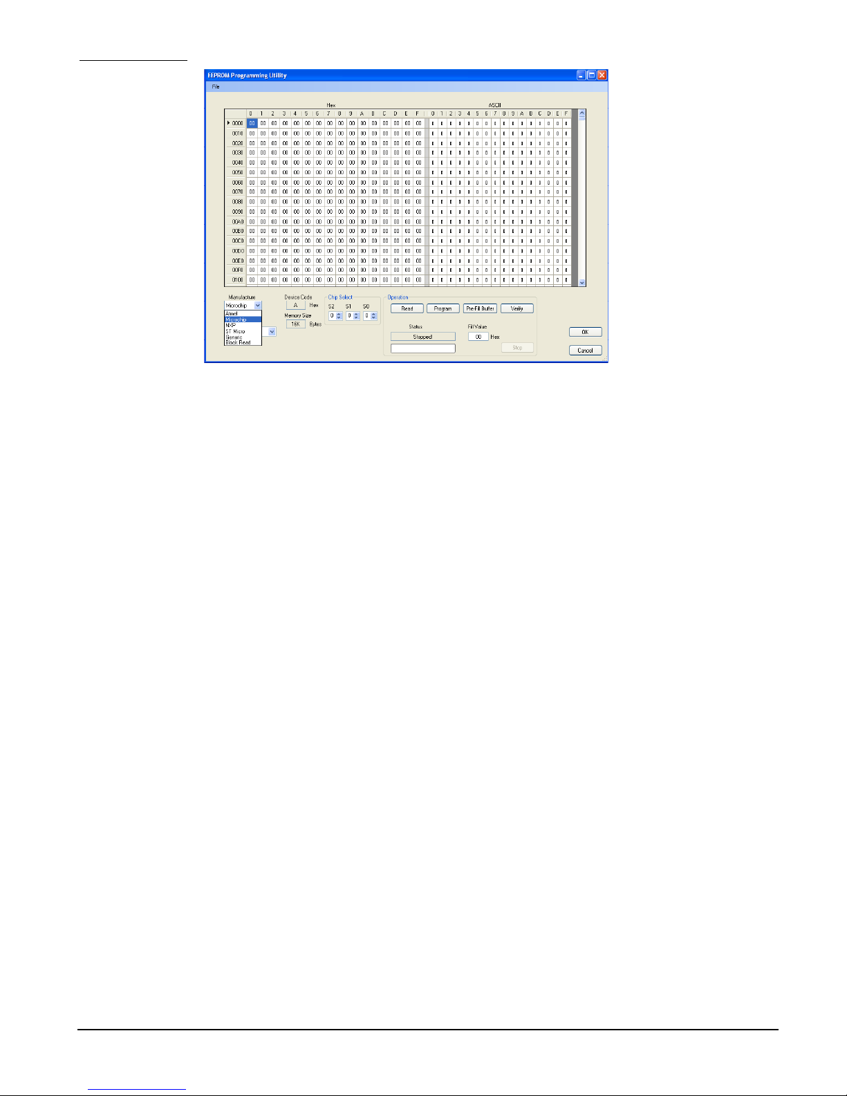
3. Verify that the EEPROM Programming Utility window is now displayed (See Figure 6)
JI-300
10
9/9/07
Page 11
Jupiter Instruments_____________________________________________________________________________________
Figure 6. EEPROM Programming Utility window
4. Enter the manufacture and device type for the target EEPROM. For this exercise, text box
data is enter as follows:
• Manufacture: ST Micro
• Device: M24C04
These two text boxes are located at the lower left-hand side of the Programming Utility
window.
5. Enter EEPROM chip select data.
• CS2: 0
• CS1: 0
• CS0: N/A
6. Now, verify device settings by successfully reading the EEPROM. This is accomplished by
clicking the Read button in the Operation group. A read time for this device is approximately
5 seconds and a successfully operation will display “Done!” in the status text box.
7. Next, fill the Buffer with ASCII “space” characters by entering 20h in the Fill Value text
box and then clicking the Pre-Fill Buffer button.
8. Verify that the Buffer contains the HEX value 20h.
9. Type the word “Top” beginning at address 000h in the ASCII section of the Buffer.
10. Type the word “Bottom” beginning at address 1f0h in the ASCII section of the Buffer.
11. Program the EEPROM by clicking the Program button.
12. A message box will appear asking, “Are you sure you want to program this device?” Click
yes. Programming begins.
13. After approximately 5 to 10 seconds programming will end and “Done Programming!” will
be displayed in status text box.
JI-300
11
9/9/07
Page 12

Jupiter Instruments_____________________________________________________________________________________
14. To verify that both Buffer and EEPROM data agree, click the Verify button. After
approximately 5 seconds, the operation will end and “Verification Successful!” will be
displayed in the Status text box.
15. To illustrate a verification error, fill the Buffer with ASCII “space” characters. As before,
enter 20h in the Fill Value text box and then click the Pre-Fill Buffer button.
16. Click the Verify button. When finished, verify that:
a. The status text box displays “Verification Error: 9 Byte(s)”
b. 9 address locations are marked red.
c. The red marked locations are where the “Top” and “Bottom” text was typed.
17. Correct the verification error by clicking the Read button. Re-verify by again clicking the
Verify button.
18. After approximately 5 seconds, verify that “Verification Successful!” is displayed in the
status text box and the text “Top” appears at the top of the Buffer and “Bottom” appears at
the bottom of the Buffer.
19. Save Buffer data to file by clicking File at the menu bar, followed by Save Buffer,
followed by Intel HEX.
20. The Save File dialog box is now displayed. Type in an appropriate file name such as
“HEXFile_Test1” and click Save.
21. Buffer data is now saved to file HEXFile_Test1.hex in an Intel HEX file format.
22. Next, the Buffer will be loaded from a file. First, however, the Buffer contents will be filled
with “X”s.
23. Enter 58h in the Fill Value text box and then click the Pre-Fill Buffer button.
24. Load Buffer data to file by clicking File at the menu bar, followed by Load Buffer,
followed by Intel HEX.
25. The Open File dialog box is now displayed. Type in the file name entered in step 20
(“HEXFile_Test1”) and click Open. Buffer data is now reloaded.
26. Verify that “Top” appears at the top of the Buffer and “Bottom” appears at the bottom of
the Buffer.
27. The EEPROM Programming exercise is now complete.
JI-300
12
9/9/07
Page 13

Jupiter Instruments_____________________________________________________________________________________
4. MAIN WINDOW AND MENU DESCRIPTIONS
4.1 Main Window
The I2C Host Adapter Main Window is shown in Figure 7.
1
2
3
11
4 5 6 78 9 10
Figure 7. I2C Host Adapter Main Window
1. Message List – I2C messages are stored here. Messages are added via the Add Message
button. To Insert, Edit, or Delete an existing message, double-click the message number.
2. Run/Stop – These buttons control the transmission of I2C messages. The Run button
initiates a session where by I2C messages stored in the message list are squelchy
executed. The session starts at the cursor position and ends either by the execution of the
lasted message in the list or by clicking the Stop button.
3. Single Step – This button is used to transmit a single I2C message.
4. Progress – Status of the current session is displayed here.
5. Reset Que – Clicking this button moves the cursor to the first message in the message list.
6. Message List Looping – This group provides control and monitoring of the message list
looping function. When Enabled, a session will cyclically execute all I2C messages stored in
the message list when a session is started. A Clear Data & Status check box provides the
option of clearing both Data and Status columns at the beginning of each loop pass.
7. 200mS Message Delay – This function, when Enabled, inserts a small delay (approx.
200ms) between each message transmission.
8. I2C Bus State – The present state of the SCL and SDA signals is displayed here.
9. External Bus Voltage – Control (On/Off) of the external bus voltage (Vbus) is performed
here.
JI-300
13
9/9/07
Page 14
Jupiter Instruments_____________________________________________________________________________________
10. USB Port – Open/Close USB port from this area.
11. Message List --
a. Add Message – Clicking this button will either add a Read or Write message to the
Message List. Messages will be appended to the bottom of the list.
b. Clear Data – Clicking this button will remove all read data from the Message List.
c. Clear Status – Clicking this button will remove all status comments from the
Message List.
d. Clear Message List – Clicking this button will remove all messages from the
Message List
4.2 Setup Menu
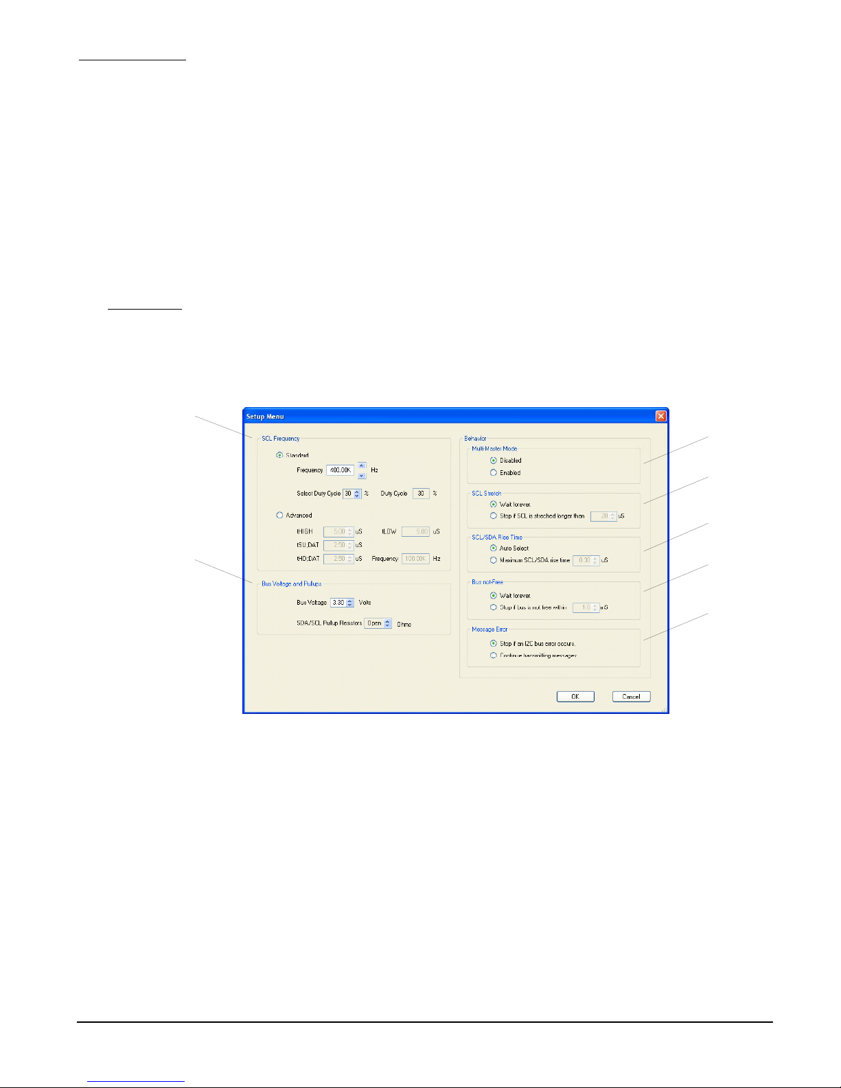
The Setup Menu provides a convenient means of configuring and maintaining an I2C hardware
setup (See Figure 8.)
1
3
2
Figure 8. Setup Menu
1. SCL Frequency – Two methods are provided to configure the SCL Clock: Standard and
Advanced. When selecting Standard, Frequency and Duty cycle data is entered and the
tHIGH, tSU,DAT, and tHD,DAT values that comprise the SCL waveform are automatically
calculated and loaded. Note that tSU,DAT, and tHD,DA values are held nearly equal (+/- 1
bit). If a unique SCL waveform is desired, the Advanced mode is selected. In this mode
tHIGH, tSU,DAT, and tHD,DAT data is entered directly. The resultant SCL frequency and
tLOW value is then calculated and displayed.
4
5
6
7
2. Bus Voltage and Pull-ups – The I2C Bus voltage and SDA/SCL pull-up resistor values are
entered here.
3. Multi-master Mode – JI-300 multi-master mode is enabled/disabled here.
JI-300
14
9/9/07
Page 15
Jupiter Instruments_____________________________________________________________________________________
4. SCL Stretch – During a Slave SCL stretch event, the behavior of the JI-300 can be
configured to:
a. Wait indefinitely on a SCL stretch event – Wait Forever selection
b. Stop if the selected SCL stretch value is exceeded.
5. SCL/SDA Rise Time – The maximum expected rise-time value for either the SCL or SDA
signal is entered here. I2C physical layer parameters such as pull-up resistors, bus voltage,
and bus capacitance can affect rise-time. Two methods are provided to configure the risetime:
a. Nominal I2C system – Auto Select selection
b. Specialized I2C system – Rise-time value is entered
6. Bus not Free – The behavior of the JI-300 can be configured to either wait indefinitely for a
“bus free” condition or stop if a “bus free” condition is not available within a specified time.
7. Message Error – In the event of a bus error during an I2C transmission session, the
behavior of the JI-300 can be configured to:
a. Stop all transmissions
b. Note the error and continue transmitting
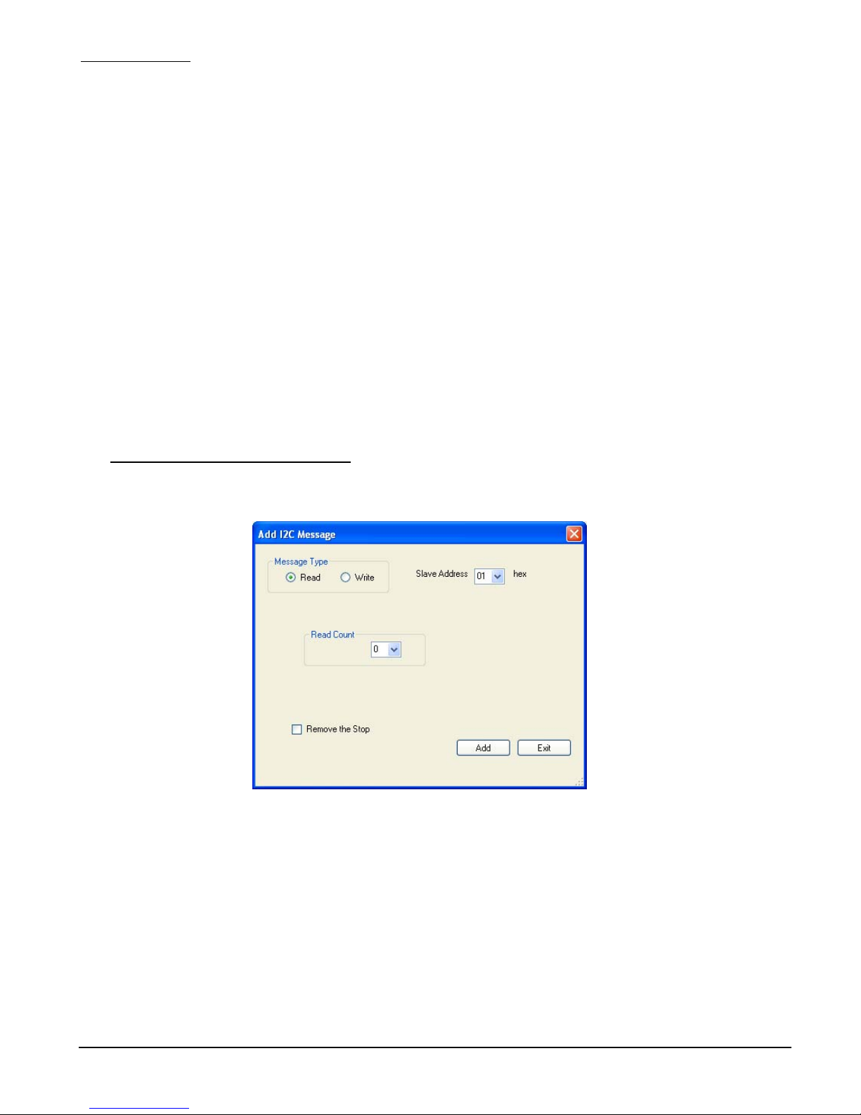
4.3 Add/Edit I2C Message Window - Read
The Add/Edit I2C Message Window - Read is used to both edit and add new Read messages to the
Message List (Figure 9.)
Figure 9. Add/Edit I2C Message Menu - Read
JI-300
15
9/9/07
Page 16
Jupiter Instruments_____________________________________________________________________________________
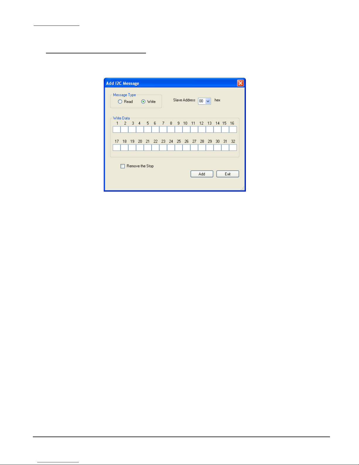
4.4 Add/Edit I2C Message Window - Write
The Add/Edit I2C Message Window - Write is used to both edit and add new Write messages to the
Message List (Figure 10.)
Figure 10. Add/Edit I2C Message Window - Write
JI-300
16
9/9/07
Page 17
Jupiter Instruments_____________________________________________________________________________________
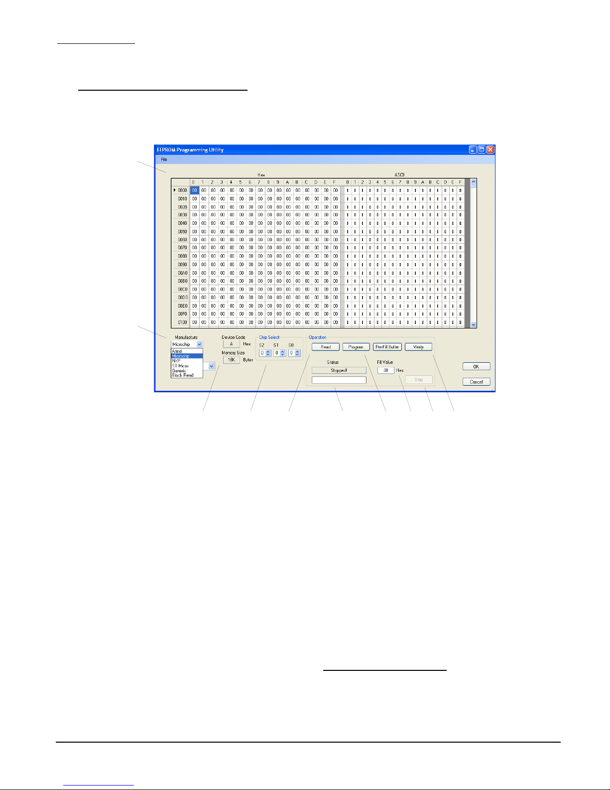
4.5 EEPROM Programming Utility window
This fully integrated programming utility is located under the Utilities tab at the main window menu
bar.
1
2
3 4 5 7 8 106 9
Figure 11. EEPROM Programming Utility window
1. Buffer – Memory data either read from, or waiting to be written to an EEPROM is displayed
here. The Buffer can be loaded (as well as saved) via several popular file formats (Intel
HEX, Motorola S-Record, and raw Binary) and edited manually using HEX values and/or
ASCII characters.
2. Manufacture & Device – Select an EEPROM by manufacture and part number or select a
generic memory device.
3. Device Code – The device code for the target EEPROM is displayed here. The code is
selected automatically for generic and commercial devices. For general-purpose block
memory, however, the code is selected manually.
4. Chip Selects – Select the state (0 or 1) of the target device chip selects (CS).
5. Read – Clicking this button reads the contents of the EEPROM into the Buffer.
6. Status – Status of the session is displayed here.
7. Program – Data from the Buffer is written to the target EEPROM device when this button is
clicked. Note: The programmed device is not automatically verified
Use the Verify function to ensure that the device was properly programmed.
8. Pre-Fill Buffer – The HEX Fill Value is copied to all locations within the Buffer. The Fill
Value data range is from 00h to ffh.
JI-300
after programming.
17
9/9/07
Page 18

Jupiter Instruments_____________________________________________________________________________________
9. Stop – If, for any reason it is necessary to immediately terminate an operation, the Stop
button is used.
10. Verify – Verify compares the content of the Buffer with that of an EEPROM device. Data
discrepancies are displayed as red-marked boxes in the Buffer. At the conclusion, operation
success or failure is displayed in the Status box.
JI-300
18
9/9/07
Page 19

Jupiter Instruments_____________________________________________________________________________________
APPENDIX A
1.0 Specifications
Hardware
PC Interface
Type: USB 2.0
Connector: Standard Type B Socket
Power
USB port: 5V @ 300mA (max) Note that all power is
supplied by the USB port.
I2C Interface
Connector: Standard 9-Pin, D-sub, Female
Pin-outs: Pin 1 = SDA
Pin 4, 5 = GND
Pin 6 = SCL
Pin 8 = Vbus
Pin 2, 3, 7, 9 = No Connection
SCL/SDA Bus Voltage
(V
bus) Range: Programmable - 1.50V to 5.25V (10mV steps) +/-2%
Input Threshold: V
VIH: 0.7Vbus (typical)
VTH: 0.1Vbus (typical)
Input Voltage Range: -0.3V to 6.0V (operational)
-5.0V to 10.0V (maximum rating)
SCL Frequency: Programmable –
SCL/SDA Sink Current: 27mA
SCL/SDA Pull-up
Resistors: Programmable – 273 to 4.99K ohms & Open (16
Input Capacitance: < 40pF without test cables
External Bus Voltage: Switched Vbus available to power external I2C
IL: 0.2Vbus (typical)
Standard: 7.0KHz to 4.0MHz
Advanced: 254Hz to 4.0MHz (20nS steps)
(typical) short–circuit protected
selections) +/-3%
target. Current limited to 90mA (typical)
JI-300
19
9/9/07
Page 20

Jupiter Instruments_____________________________________________________________________________________
LEDs
Power: Power-On (USB device enumeration)
SCL/SDA Activity: LED provides two functions:
Enclosure
Dimensions: 4.1” x 1.1” x 5.5”
Material: Vinyl-clad steel cover with an extruded aluminum
base.
Weight: 0.9 lbs.
General
I2C bus
Address Format: 7-bit
Bus Modes: Master & Multi-Master
SCL Programmable
Parameters: - t
- tHD;DAT (20nS steps)
-
Data Transfer
Tx/Rx Status Report: - Bus not-Free condition
- Clock Stretch occurrence
- SDA signal contention (Master Mode)
- Loss of arbitration (Multi-Master mode)
- Missing ACK
Behavior Setup: - Bus not Free (programmable max. time)
- Clock Stretch (programmable max. time)
- Repeated Start (Selectable)
• I2C Bus activity
• Software “Open” success - Indicated by
LED blinking three times when the software
application successfully opens a USB
connection unit.
SU;DAT (20nS steps)
tHIGH (20nS steps)
JI-300
20
9/9/07
Page 21

Jupiter Instruments_____________________________________________________________________________________
APPENDIX B
1.0 PC System Requirements
• Microsoft Windows 98*, 2000*, and XP
*These OS require the .NET framework. If installation is required, go to
http://msdn2.microsoft.com/en-us/netframework/aa569263.aspx
• USB 2.0 port
• CD-ROM drive
• 10 MB Free hard disk space
• 512 MB Memory
JI-300
21
9/9/07
Page 22
Jupiter Instruments_____________________________________________________________________________________
APPENDIX C
1. Installing USB Driver
Two types of drivers will be installed: Virtual COM Port (VCP) and Direct Drive (D2XX). The VCP
driver allows control of the JI-300 adapter via ASCII serial commands sent using a terminal
emulation program such as Windows Hyper Terminal. The D2XX driver allows direct access to a
USB device via a DLL interface. In this installation, both drivers will be installed separately. (For
additional driver information, please visit http://www.ftdichip.com/FTDrivers.htm
1. Temporarily disconnect the host PC from the Internet. (Simply remove the network cable from the
PC)
2. Insert the JI-300 CD-ROM into the computer’s CD drive.
3. Connect the JI-300 unit to a spare USB port.
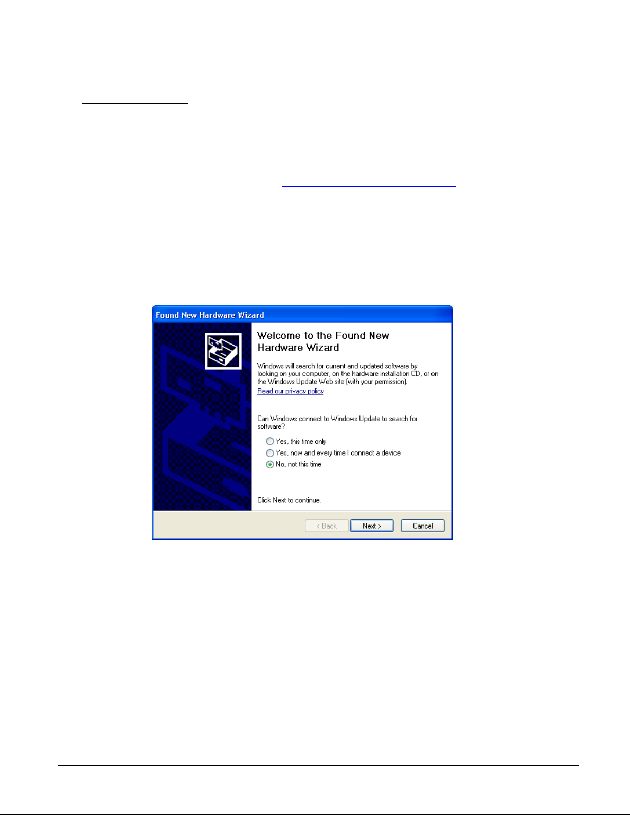
4. Now, verify that the “Found New Hardware Wizard” window is displayed as shown in Figure 1.
)
Figure 1. Found New Hardware Wizard Window
5. Select “No, not at this time” from the options, and then click “Next”.
JI-300
22
9/9/07
Page 23
Jupiter Instruments_____________________________________________________________________________________
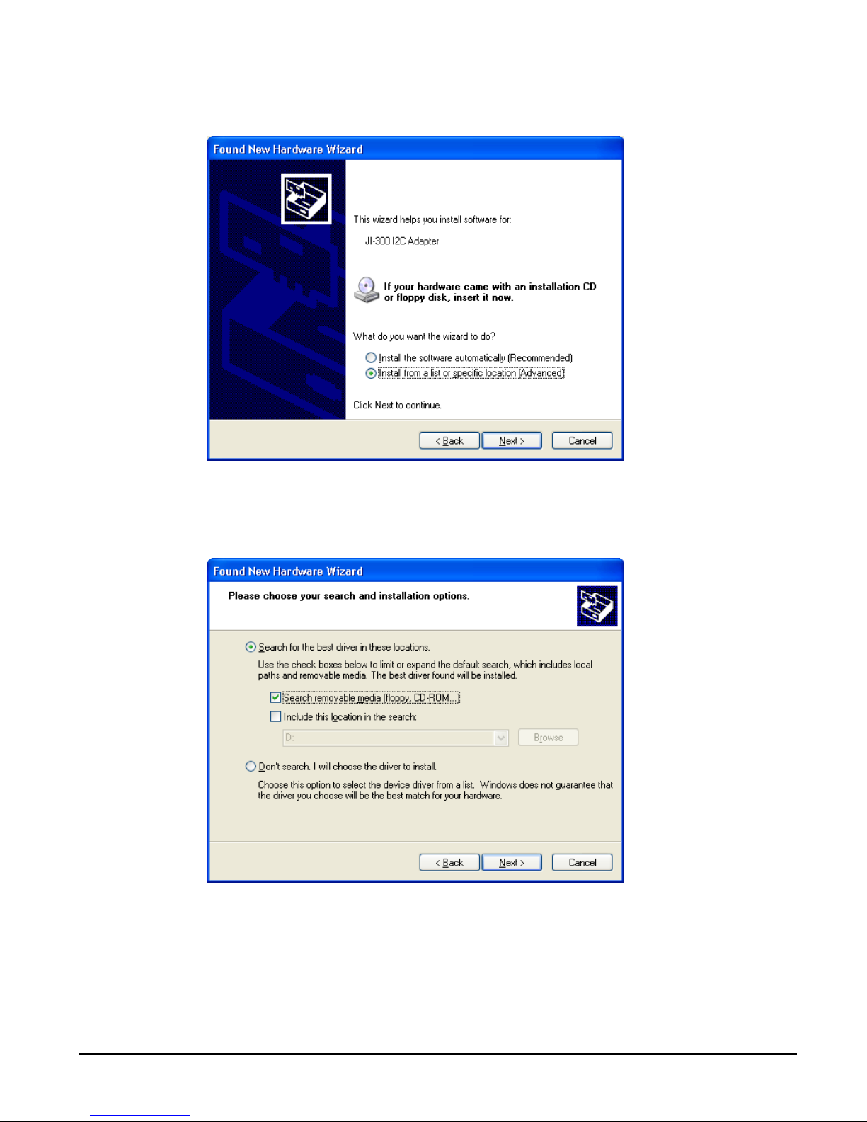
6. At the “Found New Hardware Wizard” window (Figure 2), select “Install from a specific list or
location (Advanced)”, and then click “Next”.
Figure 2. Found New Hardware Wizard Window #2
7. At the “Found New Hardware Wizard” window (Figure 3), select “Search for the best driver in
these locations” followed by “Search removable media (floppy, CD-ROM…)”. Click Next.
Figure 3. Found New Hardware Wizard Window #3
JI-300
23
9/9/07
Page 24
Jupiter Instruments_____________________________________________________________________________________
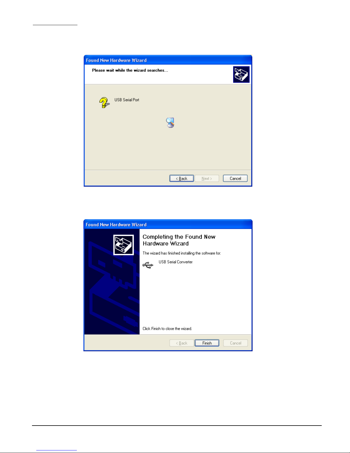
8. A window is now displayed showing the driver software being located and then copied (Figure 4).
Figure 4. Driver Coping Window
9. A window indicating that the installation was successful should now be displayed (Figure 5).
Figure 5. Installation Success Window
10. The D2XX driver is now installed. Click Next.
11. Repeat steps 5 through 11 to install the VCP driver.
12. The installation is now complete.
JI-300
24
9/9/07
Page 25

Jupiter Instruments_____________________________________________________________________________________
2.0 Installing Application Software
The JI-300 application software can be installed either locally on the host PC’s hard drive (C:) or
executed directly from CD-ROM. To install locally:
1. Insert the CD-ROM into the host PC’s CD drive.
2. Using Windows Explorer, copy the JI300 folder containing the JI-300 executable (and DLLs)
from the CD-ROM to a convenient location on the PC’s hard-drive.
3. Software installation is now complete.
JI-300
25
9/9/07
Page 26

Jupiter Instruments_____________________________________________________________________________________
APPENDIX D
1.0 General Information
1.1 Warranty
The equipment is warranted for one year from data of purchase against defects in materials or
workmanship. Jupiter Instruments reserves the right to repair or replace products at its own and
complete discretion. Customer must obtain from Jupiter Instruments a Return Authorization Number
(RMA) prior to returning any products to Jupiter Instruments. Products returned under this Warranty
must be unmodified and in original packaging. Jupiter Instruments reserves the right to refuse
warranty repairs or replacements for any products that are damaged or not in original form.
The customer is responsible for the shipping and insurance cost arising from the return of products
to Jupiter Instruments. Jupiter Instruments will return all in-warranty products with shipping cost
prepaid.
1.2 Thirty-Day Return Policy
Customers may return Jupiter Instruments products for a full refund if Jupiter Instruments is
contacted within thirty days of the customer’s receipt of the product. Customer may return Jupiter
Instruments products for credit, exchange, or a refund. Customer must obtain form Jupiter
Instruments a Return Authorization Number (RMA) prior to returning any products to Jupiter
Instruments. Products must be returned unmodified and in original packaging. Jupiter Instruments
reserves the right to refuse return rights for any products that are damaged or not in original form.
Volume orders may be subject to a significant restocking fee.
1.3 Limitation of Liability
Jupiter Instruments’ liability shall be limited to the repair or replacement of defective products in
accordance with the Jupiter Instruments limited warranty.
Jupiter Instruments shall not be liable for any incidental, special or consequential damages for
breach of any warranty, expressed or implied, directly or indirectly arising out of Jupiter Instruments’
sale of merchandise, including any failure to deliver any merchandise, or arising out of customer's
installation or use, whether proper or improper, of the product, separately or in combination with
other equipment, or from any other cause. Use the JI-210 and/or JI-300 at your own risk.
Products sold by Jupiter Instruments are not authorized for use as critical components in life support
devices or systems.
1.4 Contact Us
• Address: Jupiter Instruments
Mission Viejo, CA 92692
• Phone: Sales and Information: (949)-716-0154
• Website www.Jupiteri.com
JI-300
26
9/9/07
 Loading...