


Rev
JA77-005
Switch Plate with Removable Legends
Installation and Operating Manual
REV B
Jupiter Avionics Corporation
1959 Kirschner Road
Kelowna BC
Canada V1Y 4N7
Tel: +1 778 478 2232
Toll-Free: 1 855 478 2232
www.jupiteravionics.com
B Page i

Revision
A
B
Prepared:
Checked:
Approved:
IMPORTANT:
JA77-005 Switch Plate with Removable Legends
Installation and Operating Manual
Copyright 2016 Jupiter Avionics Corp.
All rights reserved
Jupiter Avionics Corporation (JAC) permits a single copy of this manual to be printed or downloaded for the express use
of an installing agency. Any such electronic or printed copy of this manual must contain the complete text of this copyright
notice. Any unauthorized commercial distribution of this manual is strictly prohibited. Except as described above, no part
of this manual may be reproduced, copied, transmitted, disseminated, downloaded, or stored in any storage medium for
any purpose without the express prior written consent of JAC.
Information in this document is subject to change without notice.
To confirm the current revision status of this manual, visit the JAC website:
www.jupiteravionics
.com
RECORD OF REVISIONS
Rev Date Description ECR
May 2016 Initial release, Serial number 1001 and higher. 3157
Mar 2017 Minor file changes; latest Mechanical Installation 3979
MPB
Rev B Page ii
JAC
03-29-17
SRM
JAC
03-29-17
KDV

JA77-005 Switch Plate with Removable Legends
Installation and Operating Manual
Table of Contents
SECTION 1 - DESCRIPTION ................................................................................................................................................. 1
1.1 System Overview .................................................................................................................................................... 1
1.2 Features Overview .................................................................................................................................................. 1
1.3 Inputs and Outputs .................................................................................................................................................. 1
1.3.1 Inputs ............................................................................................................................................................... 1
1.4 Specifications .......................................................................................................................................................... 1
1.4.1 Electrical Specifications................................................................................................................................... 1
1.4.2 Mechanical Specifications ............................................................................................................................... 1
SECTION 2 – INSTALLATION ............................................................................................................................................... 2
2.1 Introduction .............................................................................................................................................................. 2
2.2 Continued Airworthiness ......................................................................................................................................... 2
2.3 Unpacking and Inspecting Equipment..................................................................................................................... 2
2.3.1 Warranty .............................................................................................................................................................. 2
2.4 Installation Procedures ............................................................................................................................................ 2
2.4.1 Installation Limitations ......................................................................................................................................... 2
2.4.2 Cabling and Wiring .............................................................................................................................................. 2
2.4.3 Mechanical Installation ........................................................................................................................................ 3
2.4.4 Legend Replacement .......................................................................................................................................... 3
2.5 Legend Text Selection using ProCS™.................................................................................................................... 3
2.5.1 Front Panel Switches ...................................................................................................................................... 3
2.4.5 Post Installation Checks ...................................................................................................................................... 4
2.6 Installation Kit .......................................................................................................................................................... 4
2.6.1 Recommended Crimp tool .............................................................................................................................. 4
2.7 Installation Drawings ............................................................................................................................................... 4
SECTION 3 – OPERATION .................................................................................................................................................... 5
3.1 Introduction .............................................................................................................................................................. 5
3.2 Front Panel Controls ............................................................................................................................................... 5
3.3 Operation ................................................................................................................................................................. 5
Appendix A - Installation Drawings ................................................................................................................................... A1
A1 Introduction ............................................................................................................................................................ A1
A2 Installation Drawings ............................................................................................................................................. A1
Appendix B - Installation Documents ............................................................................................................................... B1
B1 Airworthiness Approval ......................................................................................................................................... B2
B2 Instructions for Continued Airworthiness .............................................................................................................. B2
Rev B Page iii

JA77-005 Switch Plate with Removable Legends
Name
Qty
Type
Power input
1
+28 Vdc lights power
SECTION 1 - DESCRIPTION
1.1 System Overview
The JA77-005 Switch Plate with Removable Legends allows the aircraft customizer to present a professionally
finished configurable switch panel for the ever-present extra switches.
The JA77 accepts standard aircraft grade toggle switches (i.e. Honeywell TL series or MS24523).
The legends are removable and available with any text or font. Blank legends and hole plugs (JAC Part No PLTPLUG-0003) are also available to cover unused switch holes.
1.2 Features Overvi e w
The JA77-005 has accommodation for up to four toggle switches.
The JA77-005 has two legends per switch.
Each legend is fully dimmable from a +28 Volt light dimmer bus.
Up to five characters are available per removable legend.
The Dzus plate has a baked-on flat urethane paint finish to resist scratches and nicks.
1.3 Inputs and Outputs
Refer to the JA77-005 connector map for the mating connector designators and pin assignments for the
input and output signals.
1.3.1 Inputs
1.4 Specifications
1.4.1 Electrical Specifications
Lights Input
LIGHTS INPUT Voltage 0 - 28 Vdc
LIGHTS INPUT current 100 mA max.
1.4.2 Mechanical Specifications
Height 1.875 in [47.6 mm] max
Depth behind faceplate 0.32 in [8.1 mm] max
Faceplate width 5.75 in [146 mm] max
Weight without switches 0.28 lbs. [0.13 kg] max
Material brushed aluminum with flat black
urethane finish
Connector One 2-pin male Microfit
Mounting 4 Dzus fasteners
Installation kit part number INST-JA77
Rev B Page 1

JA77-005 Switch Plate with Removable Legends
SECTION 2 – INSTALLATION
2.1 Introduction
This section contains unpacking and inspection procedures, installation information, and post-installation checks.
2.2 Continued Airworthiness
Maintenance of the JA77-005 is on condition only. Scheduled inspection and/or periodic maintenance of this unit is
not required.
2.3 Unpacking and Inspecting Equipment
Unpack the equipment carefully. Check for shipping damage and report any problems to the relevant carrier. Confirm
that the Authorized Release Certificate or Certificate of Conformance is included. Complete the on-line warranty card
from the Jupiter Avionics Corporation (JAC) website – www.jupiteravionics.com/warranty
2.3.1 Warranty
This product manufactured by JAC is warranted to be free of defects in workmanship or performance for 2 years from
the date of installation by an approved JAC dealer or agency. This warranty covers the cost of all materials and labour
to repair or replace the unit, but does not include the cost of transporting the defective unit to and from JAC or its
designated warranty repair centre, or of removing and replacing the defective unit in the aircraft. This warranty does
not cover failures due to abuse, misuse, accident, or unauthorized alteration or repairs.
THIS WARRANTY IS VOID IF THE PRODUCT IS NOT INSTALLED BY AN AUTHORIZED JAC DEALER. If the online warranty card is not completed, the product will be warranted from the date of manufacture.
Contact JAC for return authorization, and for any questions regarding this warranty and how it applies to your unit(s).
JAC is the final arbiter concerning warranty issues.
2.4 Installation Procedures
CAUTION: The power input circuitry of the unit may be damaged if the installation does not conform to the
wiring instructions in this manual.
2.4.1 Installation Limitations
Those installing the JA77, on or in a specific type or class of aircraft, must determine that the aircraft installation
conditions are within standards. The JA77 may be installed only by following the applicable airworthiness
requirements.
2.4.2 Cabling and Wiring
All wire shall be selected in accordance with the original aircraft manufacturer’s maintenance instructions, or AC43.131B Change 1, Paragraphs 11-76 through 11-78. Unshielded wire types shall qualify to MIL-W-22759 as specified in
AC43.13-1B Change 1, Paragraphs 11-85, 11-86, and listed in Table 11-11. For shielded wire applications, use Tefzel
MIL-C-27500 shielded wire with tag ring or equivalent (for shield terminations) to make the most compact and easily
terminated interconnect. Follow the Connector Map and Interconnect in Appendix A of this manual.
Maintain wire segregation and route wiring in accordance with the original aircraft manufacturer’s maintenance
instructions.
Rev B Page 2

Among the options is ‘- - - -‘ which signifies that
Clicking on a customizable legend will open a drop-
JA77-005 Switch Plate with Removable Legends
Installation and Operating Manual
Unless otherwise noted, all wiring shall be a minimum of 22 AWG. Refer to the Interconnect drawing for additional
specifications. Check that the ground connection is clean and well secured.
2.4.3 Mechanical Installation
The JA77-005 can be mounted in any attitude and location with adequate space for the front panel and sufficient
clearance for the connector and wiring harness. It requires no direct cooling.
2.4.4 Legend Replacement
The JA77-005 illuminated legends are field replaceable. For further information, refer to the ‘Legend Replacement’
document in Appendix A of this manual.
2.5 Legend Text Selection using ProCS™
The JA77-005 has no required adjustments, but the configuration program ProCS™ can be used to customize the text
for each legend either at the time of ordering the unit, or if text changes are required after installation. The JA77-005
need not be connected to a computer to select the legend text.
For information on ordering customized legends, refer to the ProCS™ Ordering Instructions on the JAC website.
2.5.1 Front Panel Switches
The Front Panel Switches window is used to specify the text for each legend.
down menu listing the options for that label. The
currently selected option will be highlighted. To escape
from the menu, click on the desired option, or right-click
in the window. A 'Print…’ box will appear. Click outside
the box to escape, or select it to print the 'Front Panel
Switches’ window showing the current label selections.
the legend will be left blank, and ‘New…’ which
allows the user to enter a completely new
legend of up to five characters. If a ‘new’
legend has been added, the option ‘Edit …’ is
added to the menu to enable changes to the
newly created label.
In the example shown here, the option ‘New…’ has been
selected. A pop-up ‘New Label’ window will appear,
allowing the user to create a customized legend – in this
case, JAC. The new legend name will now be shown in
the appropriate position on the faceplate representation
in the software program.
Rev B Page 3

Micro-Fit Crimp Tool
Tool Type
Hand crimping tool
MOLEX
63819-0000
JA77-005 Switch Plate with Removable Legends
Installation and Operating Manual
2.5.2 Post Installation Checks
2.5.2.1 Voltage/Resistance checks.
Do not attach this unit until the following conditions are met:
a) Check P9 pin 1 for +28 Vdc lights buss voltage.
b) Check P9 pin 2 for continuity to ground (less than 0.5 Ω).
c) Check all pins for shorts to ground or adjacent pins.
2.5.2.2 Configuration
Ensure that any switches inserted into the JA77-005 are configured correctly. This may be done at the factory, on the
maintenance bench or in the aircraft before the power on checks are performed.
2.5.2.3 Power on Checks.
Power up the aircraft’s systems and confirm normal operation of all functions controlled by the JA77 switches.
When all performance checks are satisfied, complete the necessary regulatory documentation before releasing the
aircraft for service. Refer to Appendix B.
2.6 Installation Kit
The kit required to install this unit is included with the unit.
The installation kit (Part # INST-JA77) consists of the following:
Quantity Description JAC Part #
1 Connector Assembly CON-8500-0001
2 Female crimp pins CON-8501-0001
2.6.1 Recommended Crimp tool
2.7 Installation Drawings
The drawings and documents required for Installation can be found in Appendix A of this manual.
Rev B Page 4

JA77-005 Switch Plate with Removable Legends
1
2
3
SECTION 3 – OPERATION
3.1 Introduction
This section contains the operating instructions for the JA77-005.
3.2 Front Panel Controls
Note: The eight legends are removable and may be replaced with custom ordered parts.
1 Switches (not included)
2 Upper legends
3 Lower legends
The JA77-005 Five Dzus Switch Plate allows the aircraft customizer to present a professional finished configurable
switch panel for extra switches. The JA77 accepts standard aircraft grade toggle switches (i.e. Honeywell TL series or
MS24523). The legends are removable and available with any text or font.
Blank legends and hole plugs are also available to cover unused switch holes.
3.3 Operation
Note: Check with your installing agency for confirmation of the operation of all switches. The legends are
interchangeable to allow customization.
Each switch position is associated with two replaceable legends; one above and one below the switch. The legends
will dim with the aircraft lighting buss.
Rev B Page 5

JA77-005 Switch Plate with Removable Legends
Installation and Operating Manual
Appendix A - Installation Drawings
A1 Introduction
The drawings necessary for installation and troubleshooting of the JA77-005 Switch Plate with Removable Legends
are in this Appendix, as listed below.
A2 Installation Drawings
DOCUMENT Rev
JA77-005 Connector Map A
JA77-005 Interconnect A
JA77-005 Mechanical Installation B
Reference Documents
TOL-CUST-EXTR Legend Replacement A
Rev B Page A1

JUPITER AVIONICS TEMPLATE AUTOCAD PORTRAIT SIZEA REV B.DWT
TITLE
APPROVED
PREPARED
CHECKED
L00N3
NCAGE CODE PART NO. SHEET
DOC NO.
CONFIDENTIAL & PROPRIETARY
TO JUPITER AVIONICS CORP.
Switch Plate with Removable Legends - Five Dzus
JA77-005 1/1
JA77-005 Connector Map Rev A.dwg
TAT
2 PIN FEMALE MICRO-FIT
MATING CONNECTOR
1 2
VIEW IS FROM REAR OF MATING CONNECTOR
LIGHTS GROUND
+28 VDC LIGHTS
P1
JAC
05-19-16
DS
JAC
05-19-16
KDV

JUPITER AVIONICS TEMPLATE AUTOCAD PORTRAIT SIZEA REV B.DWT
TITLE
APPROVED
PREPARED
CHECKED
L00N3
NCAGE CODE PART NO. SHEET
DOC NO.
CONFIDENTIAL & PROPRIETARY
TO JUPITER AVIONICS CORP.
Switch Plate with Removable Legends - Five Dzus
JA77-005 1/1
JA77-005 Interconnect Rev A.dwg
TAT
JA77-005 INTERCONNECT WIRING NOTES
NOTES
ALL WIRE SIZE SHOULD BE 24 AWG MIN UNLESS OTHERWISE SPECIFIED. UNSHIELDED WIRE
SHOULD BE SELECTED PER FAA AC43.13-1B CHANGE 1 PARA 11-76 TO 11-78. WIRE TYPES
SHOULD BE IN ACCORDANCE WITH MIL-W-22759 AS DESCRIBED IN FAA AC43.13-1B CHANGE 1
PARA 11-85 AND 11-86 AND LISTED IN TABLE 11-11 OR 11-12.
CONNECTION TO AIRFRAME GROUND SHOULD BE MADE WITH 22 AWG WIRE. LENGTH NOT TO
EXCEED 3 FT (0.91 M).
2
1.
JA77-005
P1
2 PIN FEMALE MICRO-FIT
MATING CONNECTOR
J1
+28 VDC LIGHTS 1
LIGHTS GROUND 2
+28 VDC LIGHTS
22 AWG
2
22 AWG
JAC
05-10-16
DS
JAC
05-10-16
KDV

CENTER OF GRAVITY
WEIGHT: 0.28 lbs [0.13 kg] MAX.
0.03in [0.8mm]
0.94in
23.9mm
2.87in
72.9mm
0.14in
3.6mm
1.875in MAX
47.6mm MAX
146.1mm MAX
5.75in MAX
0.49in MAX Dia.
12.4mm MAX
A
A
B
B
TITLE
CONFIDENTIAL & PROPRIETAR Y
JUPITER AVIONICS TEMPLATE SOLIDWORKS LANDSCAPE SIZEA REV B.DRW DO T
5 Dzus - Switch Plate
JA77-005 Mechanical Installation Rev B.SLDDRW
DOC. NO.
1/1
SHEET
JA77-005
PART NO.
L00N3
DRAWING NOT TO SCALE
TO JUPITER AVIONICS CORP.
APPROVED
CHECKED
TATPREPARED
N/A
N/A
MATERIAL:
FINISH:
NCAGE CODE
UNLESS OTHERWISE SPECIFIED
DIMENSIONS ARE IN INCHES
ANGLES ARE IN DEGREES
TOLERANCES:
1 DEC PLACE:
0.1
2 DEC PLACE: 0.01
3 DEC PLACE: 0.005
ANGLES: 0.5 DEG
0.32in MAX
8.1mm MAX
0.32in MAX
8.1mm MAX
SECTION A-A
SECTION B-B
JAC
SRM
03-28-17
JAC
KDV
03-28-17
Jupiter Avionics Corporation Audio Controllers
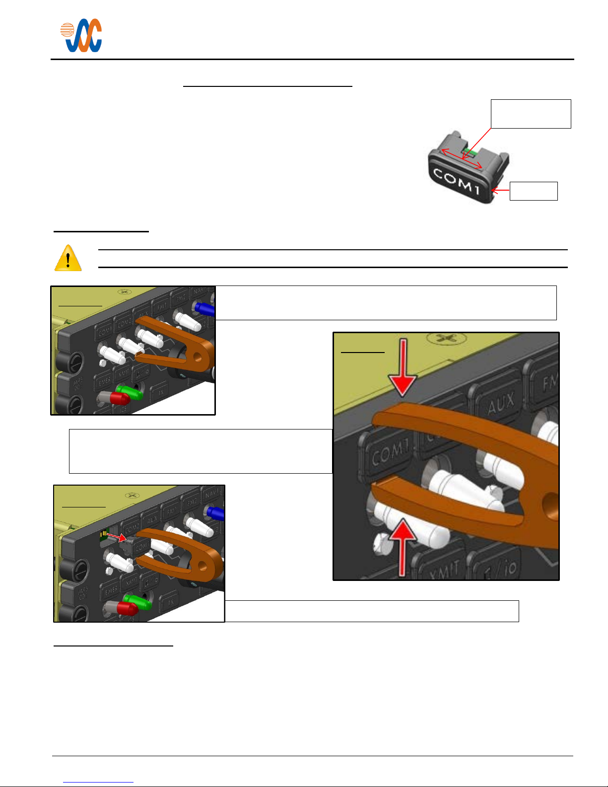
Jupiter Avionics Corporation (JAC) products have field-replaceable illuminated
To facilitate legend removal, JAC provides a legend extractor tool - part #
To remove a legend, hold the extractor firmly between
Pull the legend away from the faceplate as shown in figure 3.
Figure 1
Figure 2
Legend
Extractor tool
recess
Legend Replacement
Field-Replaceable Legends
legends. This permits easy customization, and allows the same units to be used
in multiple different configurations with only minimal changes.
The internal circuitry ensures that, although the legends are individually
illuminated, the illumination is consistent and uniform throughout all legends, and
never needs to be balanced. This means that if it is a requirement to change the
labelling due to damage or for a different project, there is no need for costly and
time-consuming illumination checks.
Legend Removal
Caution: Take care not to scratch or otherwise damage the faceplate or the legend.
TOL-CUST-EXTR (figure 1) that fits into the recesses on the legend.
the forefinger and thumb, and use a tweezer-like action
to grip the legend (figure 2).
Figure 3
Legend Replacement
To replace a legend, align the text correctly, and then apply gentle pressure until the body of the legend support seats
firmly into the faceplate.
Once the new legend is in place, ensure that it has seated correctly by checking that it illuminates. The unit is now
ready for use.
TOL-CUST-EXTR – Legend Replacement Page 1 of 1

JA77-005 Switch Plate with Removable Legends
Installation and Operating Manual
Appendix B - Installation Documents
Rev B Page B1

JA77-005 Switch Plate with Removable Legends
Installation and Oper at i ng Manual
B1 Airworthiness Approval
Airworthiness approval of the JA77-005 may require completion of a TCCA Major Modification Report per CAR STD
(AWM) 571 Appendix L, or a FAA Form 337. The sample wording for a description of the work is provided to assist
the Installing Agency in preparing Instructions for Continued Airworthiness (ICA) when installing a Jupiter Avionics
JA77-005 Switch Plate with Removable Legends. It is the installer’s responsibility to determine the applicability of the
method used. Installations performed outside Canada must follow the applicable aviation authority’s regulations.
Sample Wording:
Installed a Jupiter Avionics JA77-005 Switch Plate with Removable Legends in [aircraft location].
Installed in accordance with the JA77-005 Installation Manual, Revision [ ], and AC 43.13-2, Chapters 2, and 3.
The JA77-005 Installation Manual provides detailed installation instructions and wiring diagrams (Section 2, and
Appendices A and B).
Aircraft equipment list, weights and balance amended. Compass compensation checked and found to conform to
applicable regulations.
B2 Instructions for Continued Airworthiness
Maintenance of the JA77-005 Five Dzus - Switch Plate is “on condition” only. Periodic maintenance of the JA77-005 is
not required.
The following sample Instructions for Continued Airworthiness (ICA) provides assistance in preparing ICA for the
Jupiter Avionics JA77-005 unit installation as part of a Type Certificate (TC) or Supplemental Type Certificate (STC)
project to comply with CAR STD (AWM) 523/527/525/529.1529 or FAR 23/25/27/29.1529 “Instructions for Continued
Airworthiness”.
Items that may vary by aircraft make and model are shown in brackets (“[ ]”) and should be filled in as appropriate.
Some of the checklist items do not apply, in which case they should be marked “N/A” (Not Applicable).
Instructions for Continued Airw orthi nes s, Jupiter Avionics JA77-005 Switch
Plate with Removable Legends i n an [Aircraft Make and Model]
1. Introduction
[Aircraft that has been altered: Registration number, Make, Model and Serial Number]
Content, Scope, Purpose and Arrangement: This document identifies the Instructions for Continued
Airworthiness for a Jupiter Avionics JA77-005 installed in an [aircraft make and model].
Applicability: Applies to a Jupiter Avionics JA77-005 installed in an [aircraft make and model].
Definitions/Abbreviations: None, N/A.
Precautions: None, N/A.
Units of Measurement: None, N/A.
Referenced Publication s: JA77-005 Installation and Operating Manual
STC/TC # [applicable STC/TC number for the specific aircraft installation]
Distribution: This document should be a permanent aircraft record.
Rev B Page B2

JA77-005 Switch Plate with Removable Legends
Installation and Oper at i ng Manual
2. Description of the System/Alteration
Jupiter Avionics JA77-005 Switch Plate with Removable Legends. Refer to Appendix A of this manual for
interconnect information. Refer to aircraft manufacturer approved interconnect for actual installation.
3. Control, Operation Information
Refer to section 3 of this manual.
4. Servicing Information
N/A
5. Maintenance Instructions
Maintenance of the JA77-005 is ‘on condition’ only. Periodic maintenance is not required.
6. Troubleshooting Information
N/A
7. Removal and Replacement Information
Refer to Section 2 of this manual - the JA77-005 Installation and Operating Manual. If the unit is removed and
reinstalled, a functional check of the equipment should be conducted.
8. Diagrams
Refer to Appendix A of this manual - the JA77-005 Installation and Operating Manual - for installation drawings
and interconnect examples.
9. Special Inspection Requirements
N/A
10. Application of Protective Treatments
N/A
11. Data: Relative to Structural Fasteners
JA77-005 and appropriate mounting hardware installation, removal and replacement should be in accordance
with applicable provisions of AC 43.13-1B and AC 43.13-2A.
12. Special Tools
N/A
13. This Section is for Commuter Category Aircraft Only
A. Electrical loads: Refer to Section 1 of the JA77-005 Installation and Operating Manual.
B. Methods of balancing flight controls: N/A.
C. Identification of primary and secon d ary structures: N/A.
D. Special repair methods applicable to th e airplane: N/A.
14. Overhaul Period
No additional overhaul time limitations.
15. Airworthiness Limitation Section
N/A
Rev B Page B3
 Loading...