

Page 1
Jupiter Systems
PixelNet Domain Control
User Manual
Version 1.1
August 21, 2009
A-900-011-00, Rev. D
Page 2

Page 3

Copyright
Copyright
Copyright © 2009 Jupiter Systems. This document is copyrighted with all rights reserved.
The entire risk of the use or the result of the use of this Hardware and Software and documentation remains
with the User. Information in this document is subject to change without notice. No part of this document
may be reproduced, transmitted, transcribed, stored in a retrieval system, or translated into any language in
any form or by any means, electronic or mechanical, including photocopying without express written
permission of Jupiter Systems. See also “Statement of Limited Warranty” on page v.
Notice of Regulatory Compliance
This equipment has been tested and found to comply with the limits for a Class A digital device, pursuant
to Part 15 of the FCC rules. These limits are designed to provide reasonable protection against harmful
interference when the equipment is operated in a commercial environment. This equipment generates,
uses, and can radiate radio frequency (RF) energy and, if not installed and used in accordance with the
instructions, may cause harmful interference to radio communications. Operation of this equipment in a
residential area is likely to cause harmful interference in which case the user will be required to correct the
interference. The user is cautioned that changes or modifications not approved by Jupiter Systems can void
the user’s authority to operate this equipment.
Jupiter, Jupiter logo, and PixelNet are registered trademarks of Jupiter Systems. PDC and TeamMate are
trademarks of Jupiter Systems.
Acknowledgements
All non-Jupiter brands and names are the property of their respective owners.
Jupiter Systems
31015 Huntwood Avenue
Hayward, CA 94544-7007
510-675-1000 (v)
510-675-1001 (f)
info@jupiter.com
support@jupiter.com
510-675-1007 (v)
PixelNet Domain Control User Manual iii
Page 4

Page 5

Warranty
Statement of Limited Warranty
PixelNet Hardware
Jupiter Systems warrants that the PixelNet Hardware sold by Jupiter are free from defects in material and
workmanship and will perform in accordance with the product specification for a period of 24 months from
the date of shipment from Jupiter Systems. This warranty is in effect whether the product was purchased
directly from Jupiter or through an authorized Jupiter distributor. Any product becoming defective within
the time period specified will be repaired or replaced, at Jupiter’s option and at Jupiter’ s factory or
authorized repair center. The defective product must be returned to Jupiter or to the Jupiter authorized
repair center at the expense of the customer. Expense for the return shipment of the product to the customer
within the U.S. will be borne by Jupiter.
Products returned to Jupiter must have a Return Merchandise Authorization (RMA) number. To obtain an
RMA number contact the Jupiter repair service center at the phone number listed on the Copyright page.
PRODUCTS SHIPPED TO JUPITER WITHOUT A RETURN AUTHORIZATION NUMBER
WILL NOT BE ACCEPTED.
JUPITER’S TOTAL LIABILITY UNDER THIS WARRANTY SHALL BE LIMITED TO THE
REPA IR OR REPLACEMENT OF THE DEFECTIVE PRODUCT OR, AT JUPITER’S OPTION,
RETURN OF THE PRODUCT TO JUPITER FOR A REFUND OF THE FULL PURCHASE
PRICE. THE ABOVE WARRANTY IS THE ONLY WARRANTY APPLICABLE TO JUPITER’S
PRODUCTS AND IS THE CUSTOMER’S SOLE AND EXCLUSIVE REMEDY FOR ANY
DEFECT IN THE PRODUCTS.
Jupiter does not warrant the product for fitness for any particular purpose or application. Jupiter has no
liability for statements of functionality, performance, or configurability beyond the written product
specification for the specific Jupiter product. Jupiter shall not be held liable for incidental, indirect,
consequential, general or special damages resulting from the use or the inability to use or the failure of a
Jupiter product used in any application. No warranty, including this warranty, shall apply to any Jupiter
products that have been modified in any way, by any organization other than the Jupiter factory. The
warranty is void for products that have been subjected to misuse, improper maintenance, negligence, and/
or damage by excessive current, temperature, or accident.
Jupiter neither assumes nor authorizes any representative or other person to assume for Jupiter any other
warranty or liability in connection with the sale or shipment of Jupiter products. Jupiter reserves the right
to make changes or improvements in its products without incurring any obligation to similarly alter
products previously purchased.
PixelNet Domain Control User Manual v
Page 6

Warranty
Software Warranty and Special Provisions
Limited Warranty
Jupiter Systems warrants that the SOFTWARE will perform substantially in accordance with the
accompanying written materials for a period of ninety (90) days from the date of sale. Any implied
warranties on the SOFTWARE are limited to ninety (90) days.
Customer Remedies
Jupiter Systems’ entire liability and your exclusive remedy shall be, at Jupiter Systems’ option, either (a)
return of the price paid, or (b) repair or replacement of the SOFTWARE that does not meet this Limited
Warranty and which is returned to Jupiter Systems with a copy of your receipt or purchase order number.
This Limited Warranty is void if failure of the SOFTWARE has resulted from accident, abuse, or
misapplication. Any replacement SOFTWARE will be warranted for the remainder of the original
warranty period or thirty (30) days, whichever is longer.
No Other Warranties
To the maximum extent permitted by applicable law , Jupiter Systems disclaims all other warranties, either
expressed or implied, including but not limited to implied warranties of merchantability and fitness for a
particular purpose, with regard to the SOFTWARE and the accompanying written materials.
No Liability for Consequential Damages
To the maximum extent permitted by applicable law, in no event shall Jupiter Systems or its suppliers be
liable for any damages whatsoever (including without limitation, special, incidental, consequential, or
indirect damages for personal injury, loss of business, profits, business interruption, loss of business
information, or any other pecuniary loss) arising out of the use of or inability to use this product, even if
Jupiter Systems has been advised of the possibility of such damages. In any case, Jupiter Systems’ entire
liability under any provision of this agreement shall be limited to the amount actually paid by you for the
SOFTWARE.
vi PixelNet Domain Control User Manual
Page 7

Using this Manual
Using this Manual
Introduction
Chapter titles are at the top of every page to assist you in finding sections.
The Table of Contents is a section, chapter, and heading outline of the
manual; whereas, the comprehensive index at the end of the manual
guides you through a search of subjects, figures, and tables.
Note and Caution
This manual uses two special entries to get your attention:
• Note
• Caution
These entries are listed in their ascending order of importance. The
examples shown are found throughout this manual.
Note Notes are entries that bring your attention to specific items
that you must see, read, and understand before continuing.
Caution Cautions are entries that alert you to items that may cause
the operating system to not operate properly. For instance,
tasks that were either done out of sequence or not
supposed to be done at all may cause the system to
malfunction. Cautions also alert you about physical
connections that can cause the system to not operate
properly.
PixelNet Domain Control User Manual vii
Page 8

Page 9

Table of Contents
Copyright . . . . . . . . . . . . . . . . . . . . . . . . . . . . . . . . . . . . . . . . iii
Warranty . . . . . . . . . . . . . . . . . . . . . . . . . . . . . . . . . . . . . . . . . v
Using This Manual . . . . . . . . . . . . . . . . . . . . . . . . . . . . . . . . vii
Chapter 1. Introduction to PixelNet . . . . . . . . . . . . . . . . . . . 1
1.1 Outstanding Visual Quality . . . . . . . . . . . . . . . . . . . . . . . . . . . . . . . . . . . . . . 3
1.2 The PixelNet Difference . . . . . . . . . . . . . . . . . . . . . . . . . . . . . . . . . . . . . . . . . 3
1.3 Multiple Wall Support . . . . . . . . . . . . . . . . . . . . . . . . . . . . . . . . . . . . . . . . . . 3
1.4 Window Borders and Titles . . . . . . . . . . . . . . . . . . . . . . . . . . . . . . . . . . . . . . 4
1.5 Nodes . . . . . . . . . . . . . . . . . . . . . . . . . . . . . . . . . . . . . . . . . . . . . . . . . . . . . . . 4
1.5.1 DVI-I Input Node . . . . . . . . . . . . . . . . . . . . . . . . . . . . . . . . . . . . . . . 4
1.5.2 HD Component Input Node . . . . . . . . . . . . . . . . . . . . . . . . . . . . . . . 4
1.5.3 3G-SDI Input Node . . . . . . . . . . . . . . . . . . . . . . . . . . . . . . . . . . . . . 4
1.5.4 Quad CVBS-Y/C Input Node . . . . . . . . . . . . . . . . . . . . . . . . . . . . . 5
1.5.5 TeamMate Output Node . . . . . . . . . . . . . . . . . . . . . . . . . . . . . . . . . 5
1.5.6 Audio Output Node . . . . . . . . . . . . . . . . . . . . . . . . . . . . . . . . . . . . . 5
1.6 PixelNet Switches . . . . . . . . . . . . . . . . . . . . . . . . . . . . . . . . . . . . . . . . . . . . . . 5
1.7 PixelNet Domain . . . . . . . . . . . . . . . . . . . . . . . . . . . . . . . . . . . . . . . . . . . . . . . 6
1.8 PixelNet Domain Server . . . . . . . . . . . . . . . . . . . . . . . . . . . . . . . . . . . . . . . . . 6
Chapter 2. PixelNet Hardware . . . . . . . . . . . . . . . . . . . . . . . . 7
2.1 Hardware Overview . . . . . . . . . . . . . . . . . . . . . . . . . . . . . . . . . . . . . . . . . . . . 7
2.1.1 LED Behavior . . . . . . . . . . . . . . . . . . . . . . . . . . . . . . . . . . . . . . . . . 9
2.1.1.1 Fault LED . . . . . . . . . . . . . . . . . . . . . . . . . . . . . . . . . . . . . . . . 9
2.1.1.2 Active, Input, and Output LEDs . . . . . . . . . . . . . . . . . . . . . . . 9
2.2 HD Component Input Node . . . . . . . . . . . . . . . . . . . . . . . . . . . . . . . . . . . . . 10
2.3 DVI Input Node . . . . . . . . . . . . . . . . . . . . . . . . . . . . . . . . . . . . . . . . . . . . . . 11
PixelNet Domain Control User Manual ix
Page 10

Contents
2.3.1 EDID Switch . . . . . . . . . . . . . . . . . . . . . . . . . . . . . . . . . . . . . . . . . 12
2.4 3G-SDI Input Node . . . . . . . . . . . . . . . . . . . . . . . . . . . . . . . . . . . . . . . . . . . . 13
2.5 Quad CVBS-Y/C Input Node . . . . . . . . . . . . . . . . . . . . . . . . . . . . . . . . . . . . 14
2.6 TeamMate Output Node . . . . . . . . . . . . . . . . . . . . . . . . . . . . . . . . . . . . . . . . 15
2.6.1 SYNC Port . . . . . . . . . . . . . . . . . . . . . . . . . . . . . . . . . . . . . . . . . . . 15
2.6.1.1 Distribution Amplifier (DA) . . . . . . . . . . . . . . . . . . . . . . . . . 15
2.7 Audio Output Node . . . . . . . . . . . . . . . . . . . . . . . . . . . . . . . . . . . . . . . . . . . . 18
2.8 PixelNet Switch . . . . . . . . . . . . . . . . . . . . . . . . . . . . . . . . . . . . . . . . . . . . . . 19
2.9 PixelNet Cable . . . . . . . . . . . . . . . . . . . . . . . . . . . . . . . . . . . . . . . . . . . . . . . 20
2.9.1 Cat 6 . . . . . . . . . . . . . . . . . . . . . . . . . . . . . . . . . . . . . . . . . . . . . . . . 20
Chapter 3. PixelNet Network . . . . . . . . . . . . . . . . . . . . . . . . 21
3.1 Network Overview . . . . . . . . . . . . . . . . . . . . . . . . . . . . . . . . . . . . . . . . . . . . 21
3.2 Single Switch Configuration . . . . . . . . . . . . . . . . . . . . . . . . . . . . . . . . . . . . . 21
3.3 Dual Switch Configuration . . . . . . . . . . . . . . . . . . . . . . . . . . . . . . . . . . . . . . 23
3.3.1 Building a Dual Switch Network . . . . . . . . . . . . . . . . . . . . . . . . . . 24
3.4 Multiple Switch Configuration . . . . . . . . . . . . . . . . . . . . . . . . . . . . . . . . . . . 26
3.5 Replace Input Nodes . . . . . . . . . . . . . . . . . . . . . . . . . . . . . . . . . . . . . . . . . . . 28
3.6 Replace Output Nodes . . . . . . . . . . . . . . . . . . . . . . . . . . . . . . . . . . . . . . . . . 29
Chapter 4. PixelNet Installation . . . . . . . . . . . . . . . . . . . . . 31
4.1 Installation Overview . . . . . . . . . . . . . . . . . . . . . . . . . . . . . . . . . . . . . . . . . . 31
4.2 Pre-installation Requirement . . . . . . . . . . . . . . . . . . . . . . . . . . . . . . . . . . . . 31
4.2.1 Disabling the Network Connection in Windows XP . . . . . . . . . . . 32
4.2.2 Disabling the Network Connection in Windows Vista . . . . . . . . . 34
4.3 Installation Procedure . . . . . . . . . . . . . . . . . . . . . . . . . . . . . . . . . . . . . . . . . . 36
4.4 Installing PDC Applications . . . . . . . . . . . . . . . . . . . . . . . . . . . . . . . . . . . . . 40
4.4.1 Installing dotnetfx . . . . . . . . . . . . . . . . . . . . . . . . . . . . . . . . . . . . . 40
4.4.2 Installing WinPcap . . . . . . . . . . . . . . . . . . . . . . . . . . . . . . . . . . . . . 43
4.4.3 Power-on Sequence . . . . . . . . . . . . . . . . . . . . . . . . . . . . . . . . . . . . 46
4.5 Starting PDC . . . . . . . . . . . . . . . . . . . . . . . . . . . . . . . . . . . . . . . . . . . . . . . . 47
Chapter 5. PixelNet Domain Configuration . . . . . . . . . . . . . 51
5.1 Initial Domain Configuration . . . . . . . . . . . . . . . . . . . . . . . . . . . . . . . . . . . . 51
5.2 The Domain Connection Tab . . . . . . . . . . . . . . . . . . . . . . . . . . . . . . . . . . . . 52
5.2.1 Selecting a PixelNet Interface (Domain Connection) . . . . . . . . . . 53
5.3 The Display Wall Configuration Tab . . . . . . . . . . . . . . . . . . . . . . . . . . . . . . 54
5.3.1 Output Nodes . . . . . . . . . . . . . . . . . . . . . . . . . . . . . . . . . . . . . . . . . 56
5.3.1.1 Display Options . . . . . . . . . . . . . . . . . . . . . . . . . . . . . . . . . . 58
5.3.1.2 Audio Output Properties— Node Tab . . . . . . . . . . . . . . . . . 60
5.3.2 Output Properties . . . . . . . . . . . . . . . . . . . . . . . . . . . . . . . . . . . . . . 62
x PixelNet Domain Control User Manual
Page 11

Contents
5.4 Understanding Channel, Stream, and Source . . . . . . . . . . . . . . . . . . . . . . . . 94
5.5 Source Configuration Tab . . . . . . . . . . . . . . . . . . . . . . . . . . . . . . . . . . . . . . 102
5.3.3 Output Properties Dialog . . . . . . . . . . . . . . . . . . . . . . . . . . . . . . . . 63
5.3.3.1 Node Tab . . . . . . . . . . . . . . . . . . . . . . . . . . . . . . . . . . . . . . . . 64
5.3.3.2 Image Quality Tab . . . . . . . . . . . . . . . . . . . . . . . . . . . . . . . . 66
5.3.3.3 Display Timing . . . . . . . . . . . . . . . . . . . . . . . . . . . . . . . . . . . 68
5.3.3.4 All Parameters . . . . . . . . . . . . . . . . . . . . . . . . . . . . . . . . . . . . 71
5.3.4 Wall Configuration . . . . . . . . . . . . . . . . . . . . . . . . . . . . . . . . . . . . 73
5.3.4.1 Custom Modes . . . . . . . . . . . . . . . . . . . . . . . . . . . . . . . . . . . 76
5.3.4.2 Import Timing Parameters . . . . . . . . . . . . . . . . . . . . . . . . . . 79
5.3.4.3 Edit Custom Mode . . . . . . . . . . . . . . . . . . . . . . . . . . . . . . . . 82
5.3.4.4 Delete Custom Mode . . . . . . . . . . . . . . . . . . . . . . . . . . . . . . 84
5.3.4.5 Parameter Listing . . . . . . . . . . . . . . . . . . . . . . . . . . . . . . . . . 85
5.3.5 Assigning Nodes to Displays . . . . . . . . . . . . . . . . . . . . . . . . . . . . 86
5.3.5.1 To assign a Video node perform the following: . . . . . . . . . . 87
5.3.5.2 To assign an Audio node perform the following: . . . . . . . . . 92
5.3.5.3 Window Right-click Context Menu . . . . . . . . . . . . . . . . . . . 94
5.4.1 Single Source . . . . . . . . . . . . . . . . . . . . . . . . . . . . . . . . . . . . . . . . . 96
5.4.2 Ganged Source . . . . . . . . . . . . . . . . . . . . . . . . . . . . . . . . . . . . . . . 97
5.4.3 Grouped Source . . . . . . . . . . . . . . . . . . . . . . . . . . . . . . . . . . . . . . 98
5.4.4 Cloned Source . . . . . . . . . . . . . . . . . . . . . . . . . . . . . . . . . . . . . . . 100
5.5.1 Input Channels . . . . . . . . . . . . . . . . . . . . . . . . . . . . . . . . . . . . . . . 104
5.5.1.1 Display Options . . . . . . . . . . . . . . . . . . . . . . . . . . . . . . . . . 105
5.5.2 Source View Right-Click Context Menu . . . . . . . . . . . . . . . . . . . 106
5.5.2.1 Right-Click Context Menu for Folder . . . . . . . . . . . . . . . . 107
5.5.2.2 Right-Click Context Menu for Source . . . . . . . . . . . . . . . . 107
5.5.3 Channel Combinations . . . . . . . . . . . . . . . . . . . . . . . . . . . . . . . . . 108
5.5.3.1 Creating a Grouped Source . . . . . . . . . . . . . . . . . . . . . . . . . 109
5.5.3.2 Creating a Ganged Source . . . . . . . . . . . . . . . . . . . . . . . . . 112
5.5.3.3 Creating a Cloned Source . . . . . . . . . . . . . . . . . . . . . . . . . . 115
5.5.4 Icons . . . . . . . . . . . . . . . . . . . . . . . . . . . . . . . . . . . . . . . . . . . . . . . 116
5.5.5 Source Properties . . . . . . . . . . . . . . . . . . . . . . . . . . . . . . . . . . . . . 118
5.5.5.1 Input Source Right-click Menu . . . . . . . . . . . . . . . . . . . . . . 118
5.5.5.2 Source Properties—Source Tab . . . . . . . . . . . . . . . . . . . . . 119
5.5.5.3 Formatting Quad SD . . . . . . . . . . . . . . . . . . . . . . . . . . . . . . 121
5.5.5.4 1920x1080 Horizontal Width . . . . . . . . . . . . . . . . . . . . . . . 122
5.5.5.5 Source Properties—Cropping Tab . . . . . . . . . . . . . . . . . . . 123
5.5.5.6 Source Properties—Image Quality Tab . . . . . . . . . . . . . . . 125
5.5.5.7 Source Properties—Display Timing . . . . . . . . . . . . . . . . . . 126
5.5.5.8 Source Properties—Image Enhancement . . . . . . . . . . . . . . 129
5.5.5.9 Source Properties—Audio Tab . . . . . . . . . . . . . . . . . . . . . . 131
5.5.6 Input Channel Properties . . . . . . . . . . . . . . . . . . . . . . . . . . . . . . . 132
PixelNet Domain Control User Manual xi
Page 12

Contents
5.5.6.1 Input Channel Properties—Node Tab . . . . . . . . . . . . . . . . . 133
5.5.6.2 Input Channel Properties—Image Quality Tab . . . . . . . . . 141
5.5.6.3 Input Channel Properties—Display Timing . . . . . . . . . . . . 143
5.5.6.4 Input Channel Properties—Image Enhancement . . . . . . . . 146
5.5.6.5 Input Channel Properties—All Parameters . . . . . . . . . . . . . 148
Chapter 6. PixelNet Domain Control (PDC) Software . . . . 151
6.1 PixelNet Domain Control Window . . . . . . . . . . . . . . . . . . . . . . . . . . . . . . . 151
6.1.1 Title Bar . . . . . . . . . . . . . . . . . . . . . . . . . . . . . . . . . . . . . . . . . . . . 151
6.1.2 Tool Bar . . . . . . . . . . . . . . . . . . . . . . . . . . . . . . . . . . . . . . . . . . . . 151
6.1.3 Display Wall Tab . . . . . . . . . . . . . . . . . . . . . . . . . . . . . . . . . . . . . 153
6.1.4 Audio Window . . . . . . . . . . . . . . . . . . . . . . . . . . . . . . . . . . . . . . . 154
6.1.5 Node Monitoring . . . . . . . . . . . . . . . . . . . . . . . . . . . . . . . . . . . . . 154
6.1.6 Window Bar . . . . . . . . . . . . . . . . . . . . . . . . . . . . . . . . . . . . . . . . . 155
6.1.7 Status Bar . . . . . . . . . . . . . . . . . . . . . . . . . . . . . . . . . . . . . . . . . . . 155
6.1.8 Window Right-Click Menu . . . . . . . . . . . . . . . . . . . . . . . . . . . . . 155
6.1.8.1 Refresh Thumbnail . . . . . . . . . . . . . . . . . . . . . . . . . . . . . . . 156
6.1.8.2 Pause Channel . . . . . . . . . . . . . . . . . . . . . . . . . . . . . . . . . . . 156
6.1.8.3 Bring to Top . . . . . . . . . . . . . . . . . . . . . . . . . . . . . . . . . . . . 156
6.1.8.4 Send to Back . . . . . . . . . . . . . . . . . . . . . . . . . . . . . . . . . . . . 156
6.1.8.5 Close . . . . . . . . . . . . . . . . . . . . . . . . . . . . . . . . . . . . . . . . . . 156
6.1.8.6 Start WavePlayer . . . . . . . . . . . . . . . . . . . . . . . . . . . . . . . . 156
6.1.8.7 Stop WavePlayer . . . . . . . . . . . . . . . . . . . . . . . . . . . . . . . . . 156
6.1.8.8 Properties . . . . . . . . . . . . . . . . . . . . . . . . . . . . . . . . . . . . . . 156
6.1.8.9 Window Title—Wildcard Symbols . . . . . . . . . . . . . . . . . . 163
6.2 Sources Tab . . . . . . . . . . . . . . . . . . . . . . . . . . . . . . . . . . . . . . . . . . . . . . . . . 165
6.2.1 Dual Streams . . . . . . . . . . . . . . . . . . . . . . . . . . . . . . . . . . . . . . . . 167
6.2.2 Input Source Right-click Menu . . . . . . . . . . . . . . . . . . . . . . . . . . 168
6.2.3 Source Properties . . . . . . . . . . . . . . . . . . . . . . . . . . . . . . . . . . . . . 169
6.2.4 Sorting Options . . . . . . . . . . . . . . . . . . . . . . . . . . . . . . . . . . . . . . 170
6.2.5 Displaying a Video Source . . . . . . . . . . . . . . . . . . . . . . . . . . . . . 172
6.2.6 Displaying an Audio Source . . . . . . . . . . . . . . . . . . . . . . . . . . . . 172
6.3 Outputs Tab . . . . . . . . . . . . . . . . . . . . . . . . . . . . . . . . . . . . . . . . . . . . . . . . . 173
6.3.1 Properties . . . . . . . . . . . . . . . . . . . . . . . . . . . . . . . . . . . . . . . . . . . 174
6.4 PDC File Menu . . . . . . . . . . . . . . . . . . . . . . . . . . . . . . . . . . . . . . . . . . . . . . 174
6.4.1 Open Layout . . . . . . . . . . . . . . . . . . . . . . . . . . . . . . . . . . . . . . . . 175
6.4.2 Save Layout . . . . . . . . . . . . . . . . . . . . . . . . . . . . . . . . . . . . . . . . . 175
6.4.3 Save Layout As . . . . . . . . . . . . . . . . . . . . . . . . . . . . . . . . . . . . . . 175
6.5 PDC Configuration Menu . . . . . . . . . . . . . . . . . . . . . . . . . . . . . . . . . . . . . . 175
6.5.1 Load . . . . . . . . . . . . . . . . . . . . . . . . . . . . . . . . . . . . . . . . . . . . . . . 176
6.5.1.1 More Configuration Files . . . . . . . . . . . . . . . . . . . . . . . . . . 176
6.5.2 Manage . . . . . . . . . . . . . . . . . . . . . . . . . . . . . . . . . . . . . . . . . . . . . 177
xii PixelNet Domain Control User Manual
Page 13

Contents
6.6 PDC Tools Menu . . . . . . . . . . . . . . . . . . . . . . . . . . . . . . . . . . . . . . . . . . . . 180
6.7 Advanced Settings . . . . . . . . . . . . . . . . . . . . . . . . . . . . . . . . . . . . . . . . . . . 187
6.8 PDC View Menu . . . . . . . . . . . . . . . . . . . . . . . . . . . . . . . . . . . . . . . . . . . . . 194
6.9 PDC Help Menu . . . . . . . . . . . . . . . . . . . . . . . . . . . . . . . . . . . . . . . . . . . . . 195
6.5.3 Edit . . . . . . . . . . . . . . . . . . . . . . . . . . . . . . . . . . . . . . . . . . . . . . . 178
6.5.3.1 Editing Output Nodes . . . . . . . . . . . . . . . . . . . . . . . . . . . . . 178
6.5.4 New . . . . . . . . . . . . . . . . . . . . . . . . . . . . . . . . . . . . . . . . . . . . . . . 180
6.6.1 Reset Nodes . . . . . . . . . . . . . . . . . . . . . . . . . . . . . . . . . . . . . . . . . 181
6.6.2 Update Firmware . . . . . . . . . . . . . . . . . . . . . . . . . . . . . . . . . . . . . 182
6.7.1 Display Wall Tab . . . . . . . . . . . . . . . . . . . . . . . . . . . . . . . . . . . . . 188
6.7.1.1 Grid . . . . . . . . . . . . . . . . . . . . . . . . . . . . . . . . . . . . . . . . . . 188
6.7.2 Input Nodes Tab . . . . . . . . . . . . . . . . . . . . . . . . . . . . . . . . . . . . . . 189
6.7.2.1 Default Window Color Space Format . . . . . . . . . . . . . . . . 189
6.7.3 Configuration Tab . . . . . . . . . . . . . . . . . . . . . . . . . . . . . . . . . . . . 191
6.7.3.1 Configuration Directory . . . . . . . . . . . . . . . . . . . . . . . . . . . 191
6.7.4 Layouts Tab . . . . . . . . . . . . . . . . . . . . . . . . . . . . . . . . . . . . . . . . . 192
6.7.4.1 Layout Directory . . . . . . . . . . . . . . . . . . . . . . . . . . . . . . . . 192
6.7.4.2 Startup Layout . . . . . . . . . . . . . . . . . . . . . . . . . . . . . . . . . . . 193
6.7.5 Network Tab . . . . . . . . . . . . . . . . . . . . . . . . . . . . . . . . . . . . . . . . 193
6.7.5.1 Node Monitoring . . . . . . . . . . . . . . . . . . . . . . . . . . . . . . . . . 193
6.8.1 Node Monitoring . . . . . . . . . . . . . . . . . . . . . . . . . . . . . . . . . . . . . 194
6.8.1.1 Open Node Monitoring . . . . . . . . . . . . . . . . . . . . . . . . . . . . 194
6.8.2 Audio . . . . . . . . . . . . . . . . . . . . . . . . . . . . . . . . . . . . . . . . . . . . . . 194
Appendix A. PixelNet Node Properties . . . . . . . . . . . . . . . 197
A.1 DVI Output Properties . . . . . . . . . . . . . . . . . . . . . . . . . . . . . . . . . . . . . . . . 199
A.2 DVI Input Properties . . . . . . . . . . . . . . . . . . . . . . . . . . . . . . . . . . . . . . . . . 201
A.3 HD Component Properties . . . . . . . . . . . . . . . . . . . . . . . . . . . . . . . . . . . . . 204
A.4 3G-SDI Input Properties . . . . . . . . . . . . . . . . . . . . . . . . . . . . . . . . . . . . . . 206
A.5 Quad CVBS-Y/C Input Properties . . . . . . . . . . . . . . . . . . . . . . . . . . . . . . . 208
Appendix B. Technical Support . . . . . . . . . . . . . . . . . . . . . 211
B.1 First Line Help . . . . . . . . . . . . . . . . . . . . . . . . . . . . . . . . . . . . . . . . . . . . . . 211
B.2 Web Site . . . . . . . . . . . . . . . . . . . . . . . . . . . . . . . . . . . . . . . . . . . . . . . . . . . 211
B.3 E-Mail . . . . . . . . . . . . . . . . . . . . . . . . . . . . . . . . . . . . . . . . . . . . . . . . . . . . 211
B.4 Phone Support . . . . . . . . . . . . . . . . . . . . . . . . . . . . . . . . . . . . . . . . . . . . . . 212
B.5 Software Updates . . . . . . . . . . . . . . . . . . . . . . . . . . . . . . . . . . . . . . . . . . . . 212
B.6 Documentation . . . . . . . . . . . . . . . . . . . . . . . . . . . . . . . . . . . . . . . . . . . . . . 212
Appendix C. Return Merchandise Authorizations (RMA) . 213
C.1 Return Merchandise Authorization (RMA) Policy . . . . . . . . . . . . . . . . . . 213
PixelNet Domain Control User Manual xiii
Page 14

Contents
C.2 Shipping Policy . . . . . . . . . . . . . . . . . . . . . . . . . . . . . . . . . . . . . . . . . . . . . 214
C.3 Return Merchandise Authorization (RMA) Instructions . . . . . . . . . . . . . . 215
Glossary . . . . . . . . . . . . . . . . . . . . . . . . . . . . . . . . . . . . . . . 217
Index of Figures . . . . . . . . . . . . . . . . . . . . . . . . . . . . . . . . . 223
Index of Tables . . . . . . . . . . . . . . . . . . . . . . . . . . . . . . . . . . 229
Index . . . . . . . . . . . . . . . . . . . . . . . . . . . . . . . . . . . . . . . . . . 231
xiv PixelNet Domain Control User Manual
Page 15
Chapter 1—Introduction to PixelNet
1. Introduction to PixelNet
PixelNet offers a new and revolutionary way to capture, distribute, display,
and control digital and analog video streams. PixelNet input nodes capture
a wide variety of source signals and output nodes display them
simultaneously on a single display or display wall.
PixelNet Domain Control User Manual 1
Page 16

1—Introduction to PixelNet
The PixelNet distributed node system is one of the chief advantages of
using individual input and output nodes. This distributed node system
allows installation of nodes at the signal source and/or display device.
This distributed network system allows for simple Cat 6 cabling
between sources, displays, and the PixelNet Switch rather than
expensive analog or digital cables.
Based on a switched, proprietary network, PixelNet consists of input nodes
and output nodes that connect through a PixelNet Switch to a display wall
via standard Cat 6 network cabling. PixelNet makes creating complex
topologies of inputs, outputs, and display walls simple, inexpensive, and
future proof.
PixelNet
has the ability to capture the wide variety of source signals found
within a control room, and display them simultaneously on a display wall,
ancillary displays, even across multiple rooms. Based on standard Cat 6
cabling, PixelNet input and output nodes can be placed as far as 100m
from a PixelNet Switch. A PixelNet network automatically configures in the
field, every input node is visible to each output node.
All of this power and flexibility is managed by Jupiter’s PixelNet Domain
Control (PDC) software, providing an intuitive, object-oriented, drag-anddrop interface to control and manage multiple inputs, outputs and display
walls.
Key Terms
Node - An active electronic device that is attached to a network, and is
capable of sending, receiving, or forwarding information over, to, or from
that network.
PixelNet Domain – An interconnected set of switches and PixelNet nodes
creating a non-blocking set of gigabit ports to which the PixelNet nodes are
connected. Organized and managed via PixelNet Domain Control software.
Non-Blocking – The non-blocking PixelNet switch provides for switching
such that multiple paths through the switch do not affect each other nor
any other path in the switch. Full bandwidth is always realized through the
switch.
2 PixelNet Domain Control User Manual
Page 17

Outstanding Visual Quality
1.1 Outstanding Visual Quality
PixelNet captures video signals at full resolution, frame rate, and color
depth assuring exceptional visual performance.
Format conversion, de-interlacing, scaling, noise-reduction and colorspace conversion are all performed automatically for the user within
PixelNet – resulting in perfect representation regardless of input signal or
display device.
PixelNet’s output node, TeamMate, can display a single or multiple sources
in freely scalable windows, or multiple TeamMate nodes can be combined
together to create a display wall of virtually any size with source windows
being able to span one or all displays. All TeamMate nodes connected to
PixelNet have access to all connected inputs.
1.2 The PixelNet Difference
The PixelNet Network is a high-bandwidth, non-blocking switched network.
Data transmission from one PixelNet node to another is completely
independent of other communicating nodes. Networks are automatically
self-organizing, and PixelNet nodes exchange visual data in a common,
digital format. Nodes have very long Mean Time Between Failure (MTBF). A
failed node can easily be replaced.
All connections between nodes and switches are made using common
Cat 6 cables up to 100 meters in length. PixelNet is completely digital in
nature, and with digital input sources such as a DVI computer source or
SDI video, the network can be digital end-to-end, resulting in the best
possible visual performance. Video signals are enhanced through the use
of superior video processing technology for de-interlacing and antialiasing. The result is a broadcast-quality display. Any application will
benefit from the simple installation and superb visual performance of a
PixelNet network.
1.3 Multiple Wall Support
With PixelNet, it is now possible to manage multiple displays in widely
separated locations, and to control them independently. This new feature
expands the boundaries of any given PixelNet domain and can include
many display walls. Content is no longer confined to a single display wall;
it can now be presented in more than one place on a variety of display
types.
PixelNet Domain Control User Manual 3
Page 18

1—Introduction to PixelNet
1.4 Window Borders and Titles
PixelNet now offers options to apply colored borders to any window on the
display wall and add titles to the borders using a text editor. Window
layouts can be saved and instantly recalled on the wall, including the
borders and titles.
1.5 Nodes
1.5.1 DVI-I Input Node
Jupiter Systems designed the DVI-I Input Node to capture analog (RGB)
and digital progressive scan (DVI) signals from graphical outputs of other
computers. Resolutions up to 2048 x 1200 and a pixel clock up to 165 MHz
are supported.
The DVI-I input node supports analog and digital loop-through from the
source to a display or another input node. The DVI-I input node
automatically detects incoming signal formats for plug-and-play simplicity .
Each input node contains two gigabit PixelNet ports.
1.5.2 HD Component Input Node
The HD Component Input Node is designed to capture incoming SDTV
(NTSC/PAL/SECAM) and HDTV (ATSC) signals, and accepts analog
component inputs (YPrPb). This is an audio-capable input node that
supports stereo and 5.1 encoding formats: 48KHz, 44.1KHz, 24bit.
The HD Component input node automatically detects incoming signal
formats for plug-and-play simplicity. Each input node contains two gigabit
PixelNet Ports.
1.5.3 3G-SDI Input Node
The 3G-SDI Input Node is designed to support 3G-, HD-, and SD-SDI
signals—3G (1080 p), HD (720 p, 1080i), and SD (480 i/p, 576 i/p)—at 50
or 60 fps. This is an audio-capable input node that supports stereo and 5.1
encoding formats: 48KHz, 44.1KHz, 24bit.
The 3G-SDI input node provides SDI signal loop-through and 10-bit color
processing. Similar to the other input nodes, the 3G-SDI input node
automatically detects incoming signal formats for plug-and-play simplicity .
Each input node contains two gigabit PixelNet Ports.
4 PixelNet Domain Control User Manual
Page 19

PixelNet Switches
1.5.4 Quad CVBS-Y/C Input Node
The Quad Composite Video Broadcast Standard and S-Video (CVBS-Y/C)
Input Node is designed to support SD signals—SD (480 i, 576 i)—at 25 or
30 fps. This input node handles NTSC/PAL/SECAM composite and S-Video
signals. This node allows for four channels to be processed simultaneously.
1.5.5 TeamMate Output Node
Jupiter Systems designed the TeamMate Output Node to provide DVI and
analog display signals to graphical display devices (such as flat-panels,
projectors, cubes, etc.) Resolutions up to 2048 x 1200 and a pixel clock up
to 165 MHz are supported.
The T eamMate output node provides for an optional FrameLock, wherein all
output nodes are connected to a single SYNC signal. In a display wall
environment, there will be one master SYNC output node supplying the
SYNC signal to all other output nodes. Each output node contains two
gigabit PixelNet Ports.
1.5.6 Audio Output Node
The PixelNet Audio output node routes audio associated with video data
captured at audio-capable PixelNet input nodes (the 3G-SDI and HD
Component input nodes). Audio configurations are saved as part of
PixelNet Domain Control layouts and are automatically recalled when the
associated layout is selected. Unlike other solutions, PixelNet users will be
able to both see and hear a source, managing the two capabilities through
a drag-and-drop interface.
Digital audio can be transferred optically over fiber optic TOSLINK (Toshiba
LINK) F05 connectors or Bayonet Neill-Concelman (BNC) 75 Ohm coax
cables can be used. Also, the AES-3id standard is supported.
1.6 PixelNet Switches
Each PixelNet Network requires the use of at least one 48-port PixelNet
Switch. PixelNet switches are based on a proprietary switching network
and can not be used within a standard Ethernet network.
PixelNet Domain Control User Manual 5
Page 20

1—Introduction to PixelNet
1.7 PixelNet Domain
A PixelNet Domain is a network configuration that consists of a
combination of input nodes, output nodes, one or more PixelNet switches,
and a PixelNet Domain Server running PixelNet Control Software.
1.8 PixelNet Domain Server
In order to run the PixelNet Domain Control Software, the PixelNet Domain
Server requires a dedicated gigabit Ethernet port with jumbo packet
support. Furthermore, all of the items shown in the Connection
Properties list must be disabled (unchecked), before using the Server.
6 PixelNet Domain Control User Manual
Page 21
Chapter 2—PixelNet Hardware
2. PixelNet Hardware
2.1 Hardware Overview
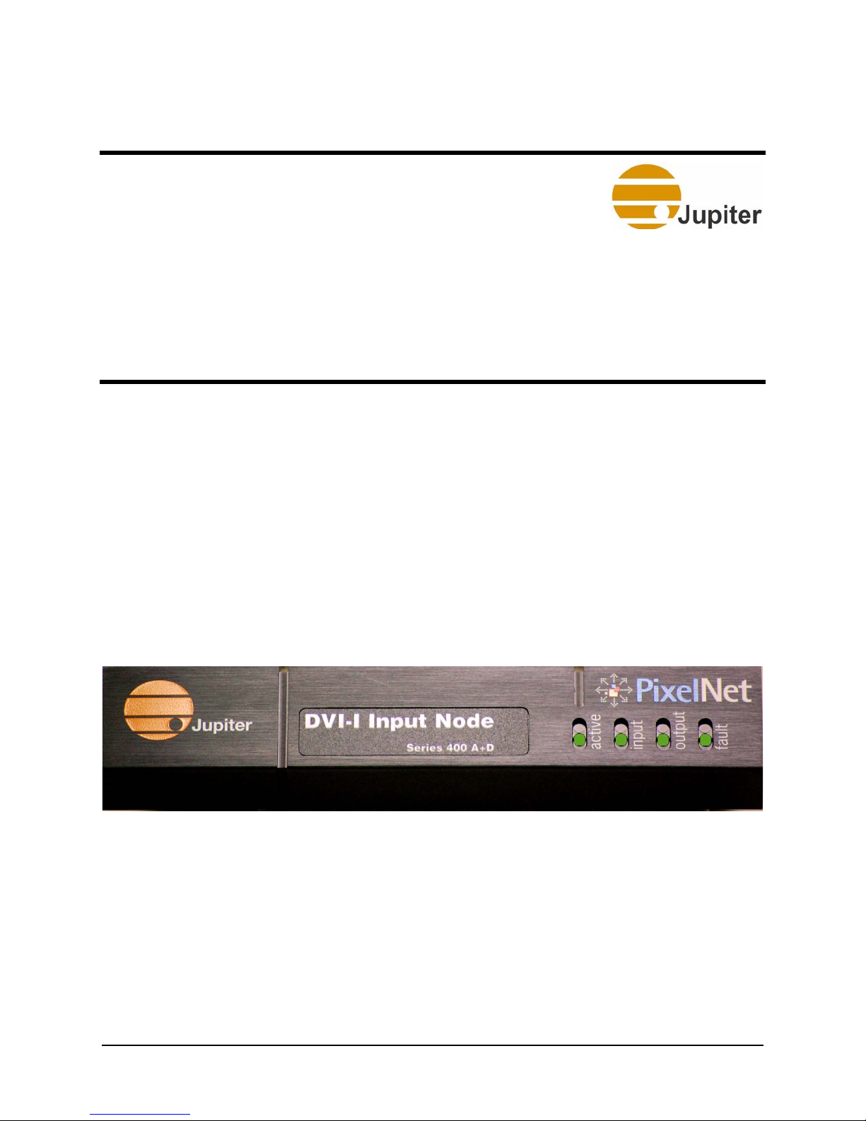
This chapter describes the hardware characteristics of the PixelNet DVI-I
input node (“Figure 1”), the PixelNet HD Component input node
(“Figure 2”), PixelNet 3G-SDI input node (“Figure 3” on page 8),
Quad CVBS-Y/C input node (“Figure 4” on page 8), PixelNet output
node (“Figure 5” on page 8), and the 48-port PixelNet Switch (“Figure
15” on page 19).
Figure 1 - PixelNet DVI-I Input Node Front Panel
PixelNet Domain Control User Manual 7
Page 22
2—PixelNet Hardware
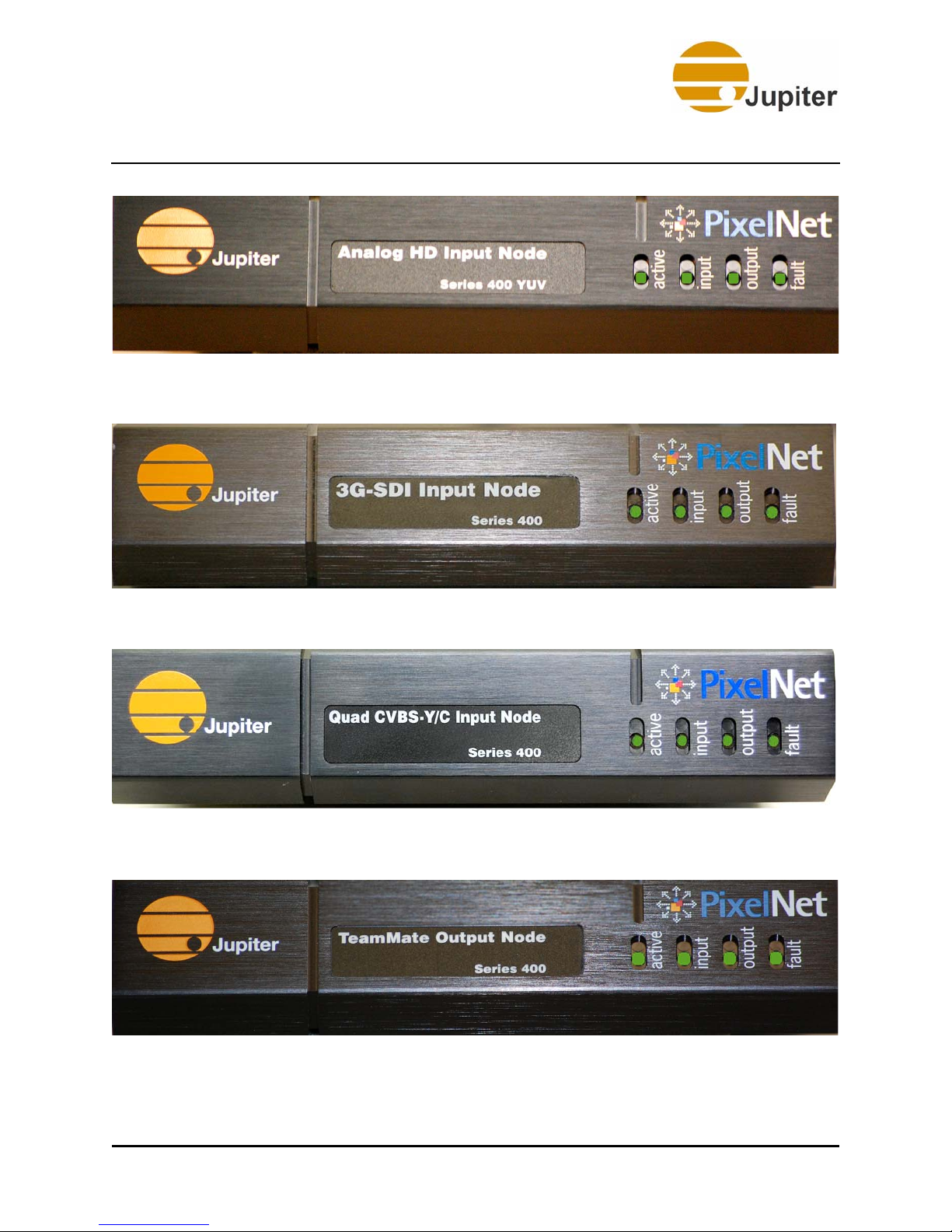
Figure 2 - PixelNet HD Component Input Node Front Panel
Figure 3 - PixelNet 3G-SDI Input Node Front Panel
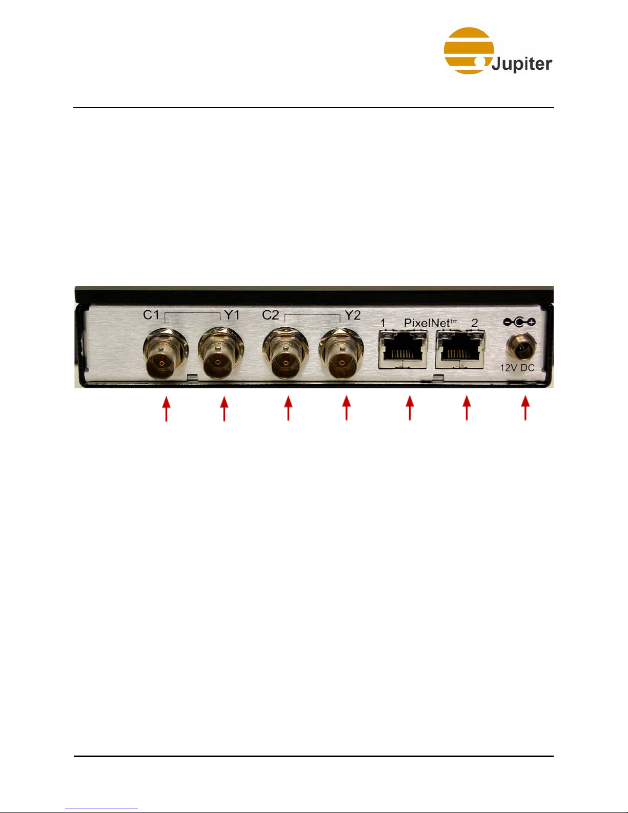
Figure 4 - PixelNet Quad SD Input Node Front Panel
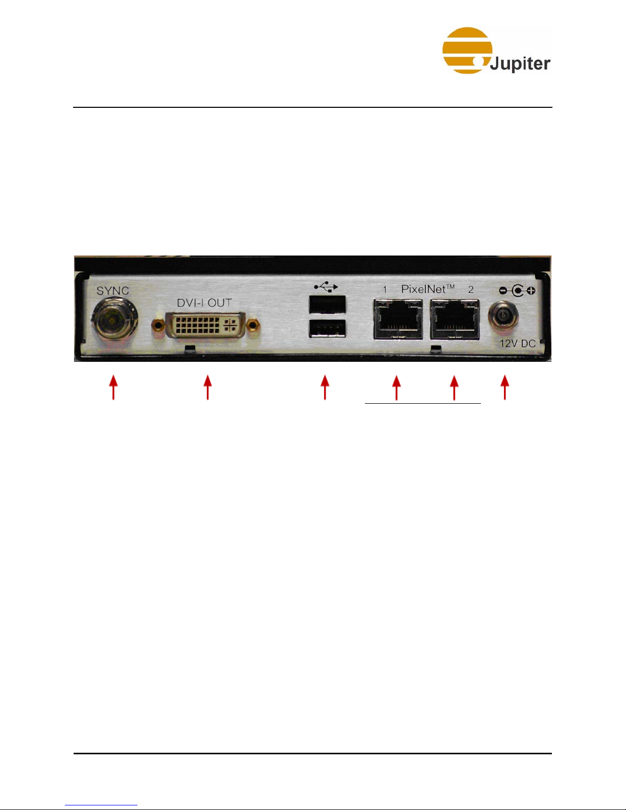
Figure 5 - PixelNet Output Node Front Panel
8 PixelNet Domain Control User Manual
Page 23
Hardware Overview
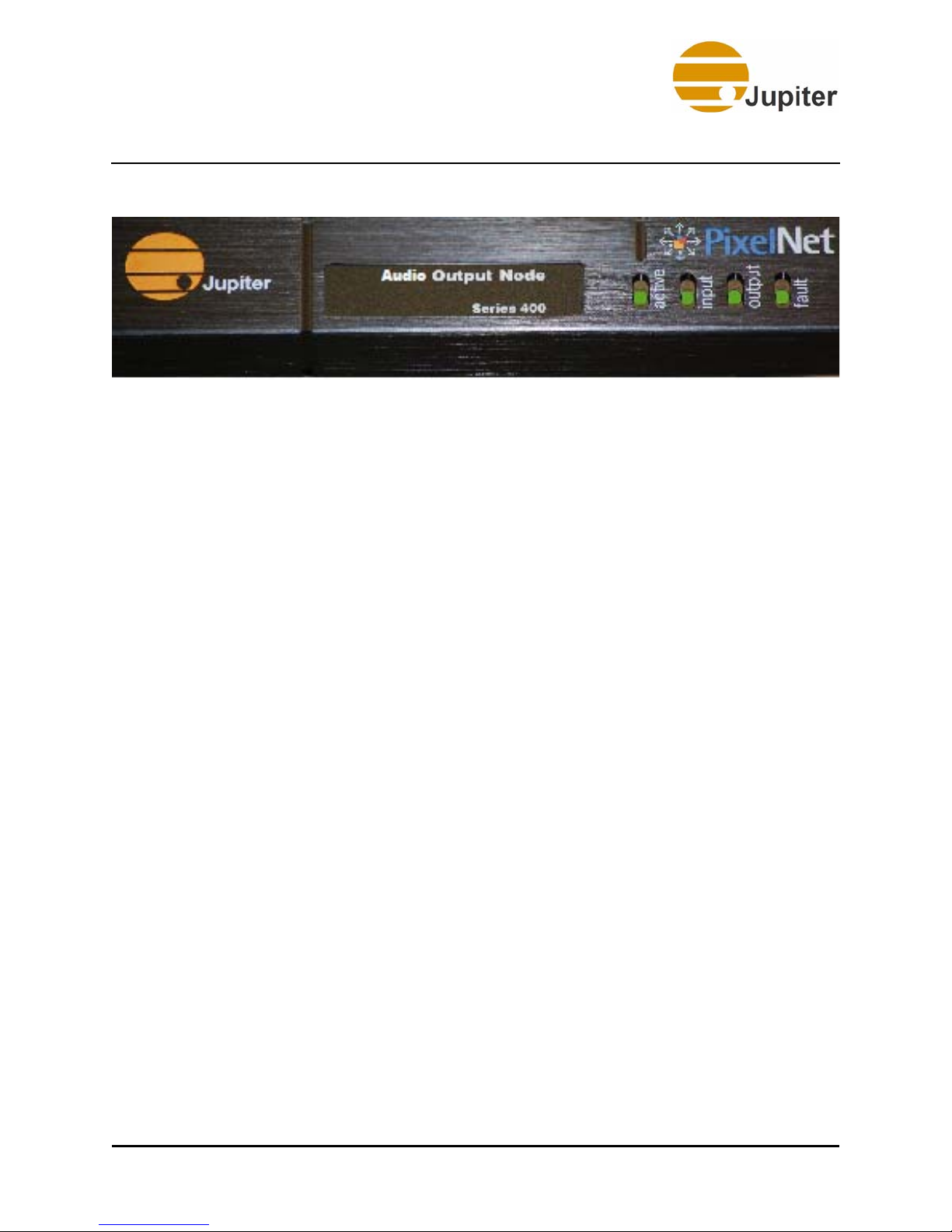
Figure 6 - PixelNet Audio Output Node Front Panel
2.1.1 LED Behavior
The PixelNet nodes contain four LEDs—Active, Input, Output, and Fault.
The Active, Input, and Output LEDs must be interpreted in conjunction
with the Fault LED color.
2.1.1.1 Fault LED
The Fault LED colors (red, yellow, and green) indicate the node’s functional
status through its Power-up, Operational, and Fault modes.
Power-up Mode
As the node powers-up, the Fault LED remains yellow. If the Fault LED
turns red, the node is experiencing internal or power problems. During
startup the active, input, and output LEDs will flash through different
colors.
Operational Mode
Once the power-up is complete, the node is in operating mode. The Fault
LED turns green.
Fault Mode
When the Fault LED is red, the node is not functioning and is in a fault
mode. Attempt a power-cycle of the node; if Fault LED is still red, contact
Jupiter Technical Support for assistance.
2.1.1.2 Active, Input, and Output LEDs
When the Fault LED is Red:
The Active, Input, and Output LEDs will show a specific static display of
red, yellow, green, and off. You should make a note of this LED display
sequence and call Jupiter Technical Support so that we can decipher the
Fault code and resolve the issue.
PixelNet Domain Control User Manual 9
Page 24

2—PixelNet Hardware
When the Fault LED is Yellow:
The Active, Input, and Output LEDs will show a combination of LED
displays while the node is in the process of powering up.
Note So far, the LED behavior has been the same for both the
Input and Output nodes. However, when the Fault LED is
green the LED behavior changes depending on whether it is
an Input or Output node.
When the Fault LED is Green:
In an input node:
• The Input LED is green when it has a valid signal, or yellow if the
source is not detected.
• The Active LED is green when actively processing data or yellow
when idle.
• The Output LED is green when it is sending packets (a data
stream) or yellow when idle.
In an output node:
• The Output LED is green when it is connected to a display device
• The Active LED is green when actively processing data or yellow
when idle.
• The Input LED is green when it is receiving packets (a data
stream) or yellow when idle.
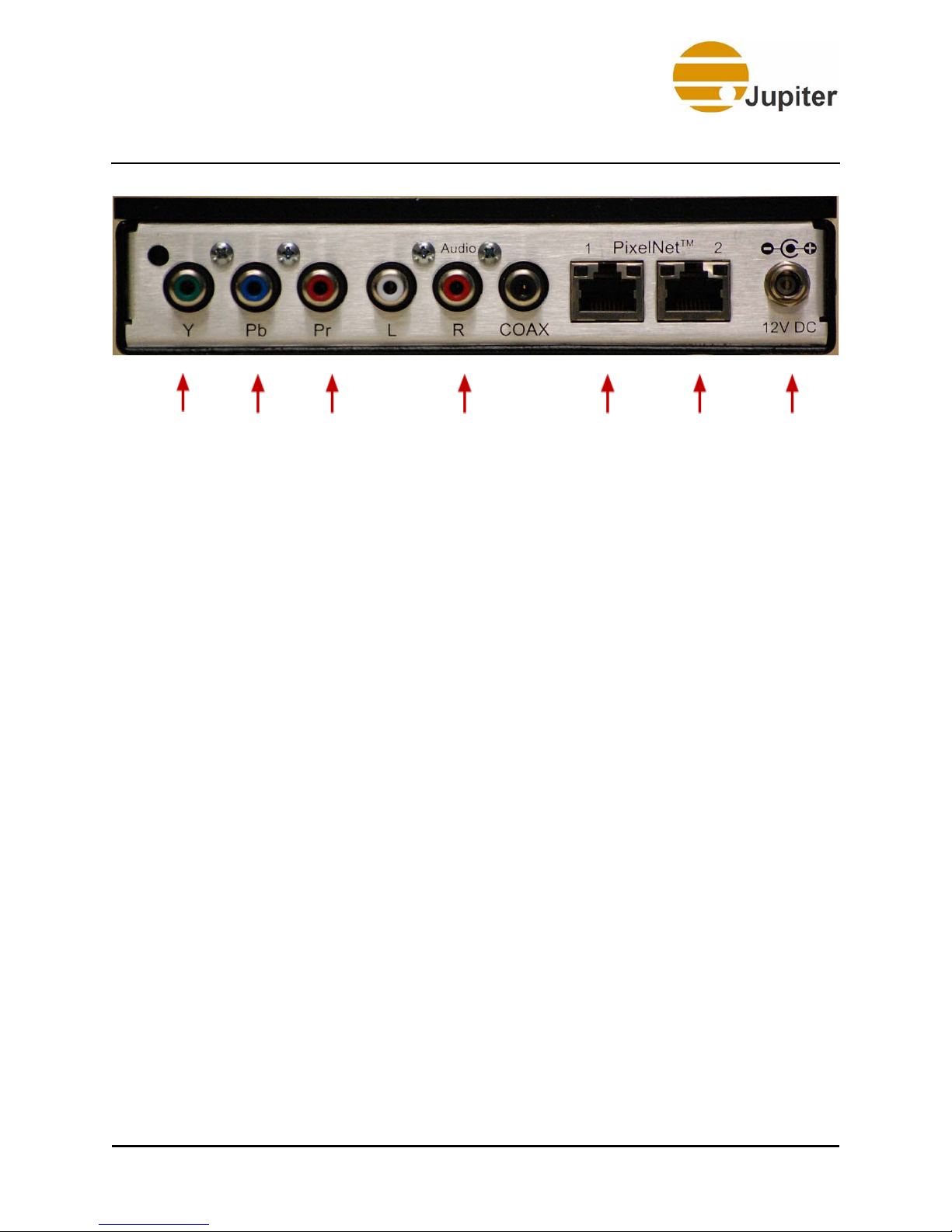
2.2 HD Component Input Node
• Supports SDTV (NTSC/PAL/SECAM) and HDTV (NTSC)
• Provides analog component inputs (YPrPb)
• Provides automatic format detection for plug-and-play simplicity
• Provides two gigabit PixelNet ports
10 PixelNet Domain Control User Manual
Page 25
DVI Input Node
Y
Input
Pb
Input
Pr
Input
Figure 7 - HD Input Node Rear View
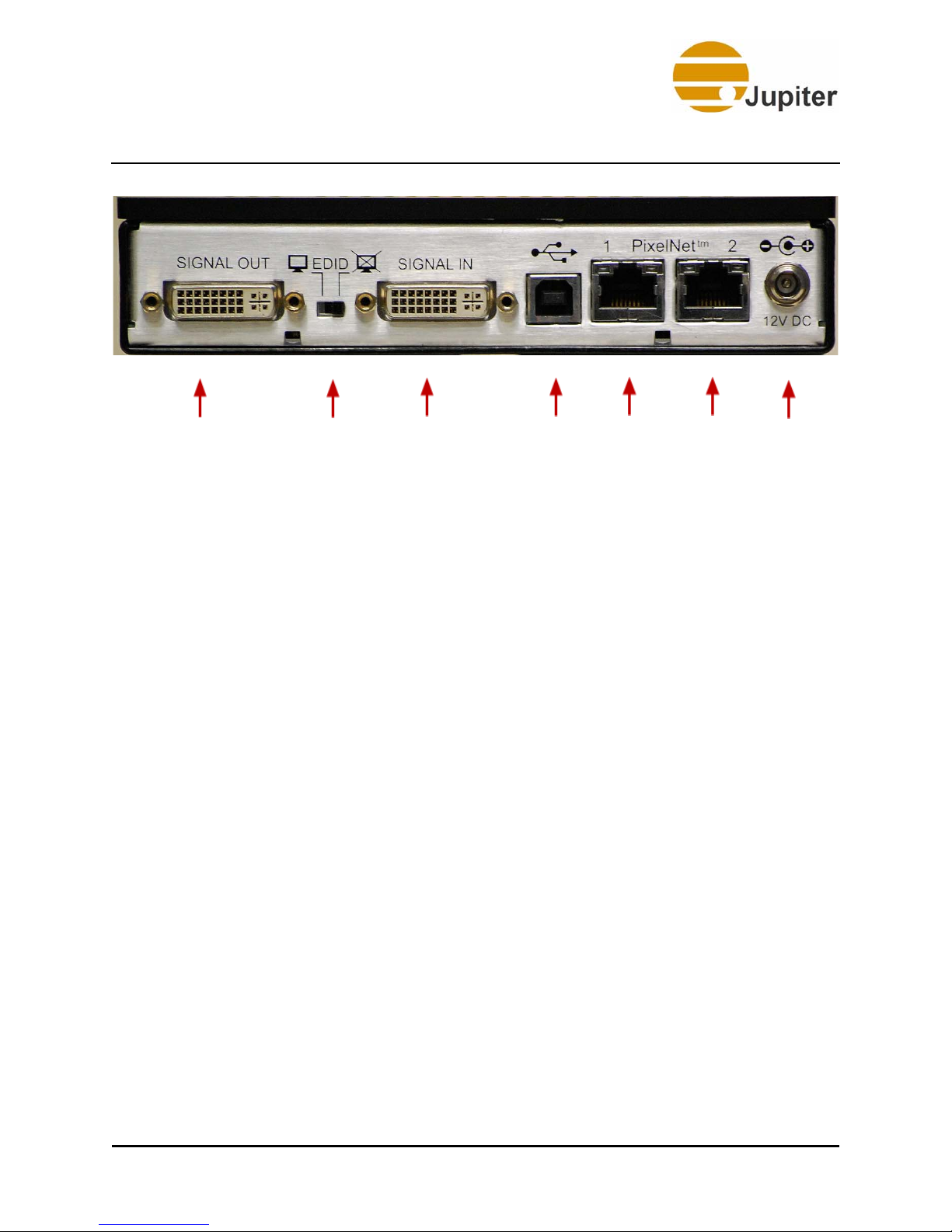
2.3 DVI Input Node
• Captures signals up to 2048 x 1200 resolution and up to 165 MHz
pixel rate
• Captures analog or digital progressive scan signals
• Supports analog-to-analog and digital-to-digital loop-through
• Provides choice of external (loop-through) or internal EDID
• Provides automatic format detection for plug-and-play simplicity
• Provides two gigabit PixelNet ports
“Figure 8” on page 12 shows the rear panel of the DVI input node.
Cable connections are also indicated in the figure. Note that the USB port
is reserved for future capabilities. The node is also capable of providing a
duplicate of the input signal. The signal type presented at the SIGNAL IN
connector DVI-I (DVI-D or analog RGB) will be duplicated at the SIGNAL
OUT connector, i.e. analog-to-analog or digital-to-digital. This allows a
monitor connected to the SIGNAL OUT connector to receive the same
signals present at the SIGNAL IN.
Left, Right, and Coaxial
audio connections
PixelNet
Port 1
PixelNet
Port 2
Power
PixelNet Domain Control User Manual 11
Page 26
2—PixelNet Hardware
DVI-I
Input
E D I D
Switch
Figure 8 - DVI Input Node View
DVI-I
Input
USB not currently
supported
PixelNet
Port 1
PixelNet
Port 2
Power
2.3.1 EDID Switch
Display Data Channel (DDC) is a communication standard used by graphics
channels of PCs to talk to monitors. The DDC uses the Extended Display
Identification Data (EDID) to find out information about what the system
supports regarding preferred resolution and color depth.
The EDID Switch allows two settings, left and right, the operation of the
DVI-I input node depends on the following criteria:
• When a monitor is connected to Signal Out (with the switch to
the left towards the monitor icon), the PC connected to the
Signal In connector requests the monitor for the EDID table and
verifies the information so that an acceptable resolution value is
used by the PC. This resolution will also be used by the DVI-I
input node.
• With the switch to the right towards the crossed-out monitor
icon, the PC connects to an internal chip in the node with a builtin EDID table to get information about the maximum resolution
that the node will support.
12 PixelNet Domain Control User Manual
Page 27
3G-SDI Input Node
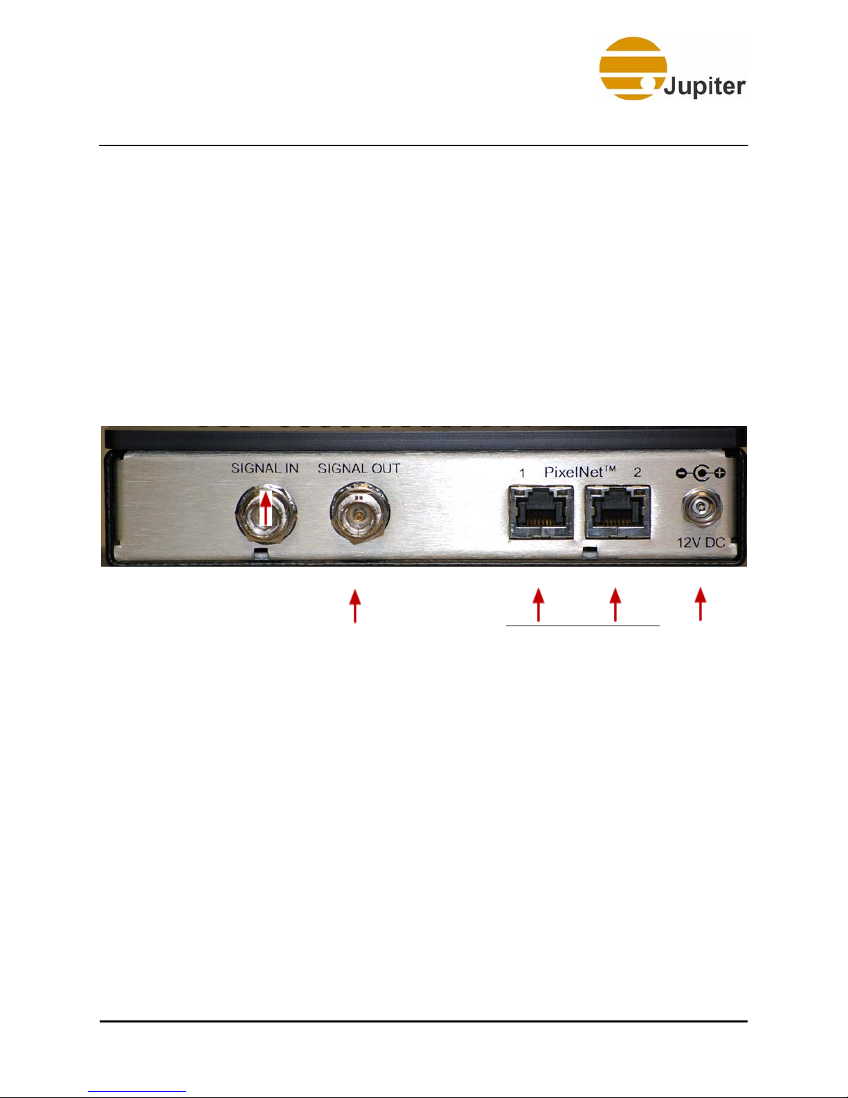
2.4 3G-SDI Input Node
• Supports 3G-, HD-, and SD-SDI signals:
• 3G (1080 p), HD (720 p, 1080 i), and SD (480 i/p, 576 i/p)—at
50 or 60 fps
• Handles SMPTE 424M-A, SMPTE 292M, and SMPTE 259M
(NTSC/PAL) signals
• Supports automatic format detection for plug-and-play simplicity
• Provides SDI signal loop-through
• Provides 10 bit color processing
• Provides two gigabit PixelNet ports
Signal In Signal Out PixelNet
Figure 9 - PixelNet 3G-SDI Input Node Rear View
Port 1
PixelNet
Port 2
Power
“Figure 9” on page 13 shows the rear panel of the 3G-SDI input node.
Cable connections are also indicated in the figure. The 3G-SDI input node
also provides loop through output. The signal type presented at the
SIGNAL IN connector will be duplicated at the SIGNAL OUT connector.
PixelNet Domain Control User Manual 13
Page 28
2—PixelNet Hardware
2.5 Quad CVBS-Y/C Input Node
• Supports SD signals:
• SD (480 i, 576 i)—at 25 or 30 fps
• Handles NTSC/PAL/SECAM components, and S-Video signals
• Supports automatic format detection for plug-and-play simplicity
• Provides 8-bit 4:2:2 color processing
• Provides two gigabit PixelNet ports
C1
Chromi-
nance
S-Video S-Video
Figure 10 - Quad CVBS-Y/C Input Node Rear View
Y1
Luminance
C2
Chromi-
nance
Y2
Lumi-
nance
PixelNet
Port 1
PixelNet
Port 2
Power
“Figure 10” on page 14 shows the rear panel of the Quad-CVBS-Y/C
input node. This node allows for four channels (combination of composite
or S-Video signals) to be processed simultaneously. Cable connections are
indicated in the figure; either up to two S-Video (YC1 and YC2) or up to
four composite (1, 2, 3, and 4). When an S-Video signal is connected, the
corresponding composite capability is removed, for instance, using Y1 and
C1 disables composite 1 and 2.
14 PixelNet Domain Control User Manual
Page 29
TeamMate Output Node
2.6 TeamMate Output Node
• Supports DVI or Analog display outputs
• Supports output resolutions up to 2048 x 1200 or 165 MHz pixel
clock
• Provides two gigabit PixelNet ports
• Provides optional FrameLock, connecting all output nodes to a
single SYNC signal
SYNC DVI-I Output USB not currently
supported
Figure 11 - PixelNet Output Node Rear View
PixelNet
Port 1
PixelNet
Port 2
2.6.1 SYNC Port
The output node sync port provides for synchronizing all output node
signals to the displays. Use this if you want all the output nodes in your
configuration to be tied to a single sync signal. Synchronization allows for
full motion video with no tearing of image at display boundaries.
The first output node of a display wall will be configured as a master; by
default, all the other nodes will be configured as slaves. The master output
node is configured with the PixelNet Domain Control software.
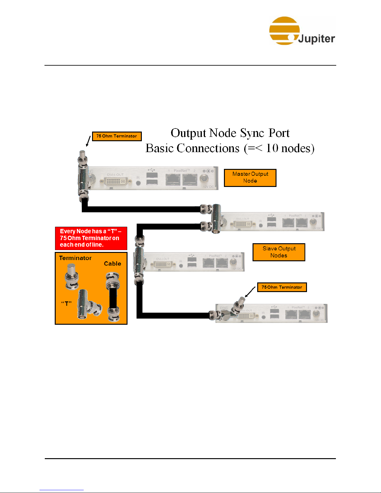
2.6.1.1 Distribution Amplifier (DA)
Up to ten output nodes can be used in a simple configuration—one master,
nine slaves. More complex systems with more than ten output nodes are
possible with a high-bandwidth Distribution Amplifier (DA). Each DA port
can support up to ten output nodes. Also, more than one DA can be daisychained from the first DA. The DA is available as a PixelNet option.
Power
PixelNet Domain Control User Manual 15
Page 30
2—PixelNet Hardware
The following figure shows the basic daisy-chain connections for the Sync
Port. Every node requires a T-Connector. Every branch of the T-Connector
will be connected. Each end of the daisy-chain has a 75 Ohm terminator
attached.
Figure 12 - Output Node Basic Sync Connections
16 PixelNet Domain Control User Manual
Page 31

TeamMate Output Node
PixelNet Networks with greater than 10 output nodes, require the use of
High-bandwidth Video Distribution Amplifiers.
Figure 13 - Output Node Sync Connections for > 10 Nodes
PixelNet Domain Control User Manual 17
Page 32

2—PixelNet Hardware
2.7 Audio Output Node
• Supports both analog and digital signals
• Optical port (S/PDIF), BNC connector (S/PDIF or AES 3id), and
two analog TRS ¼” jacks
• Frequency Response: 4Hz - 22 KHz (48 KHz sampling),
4 HZ - 44 KHz (96 KHz sampling)
• Signal-to-Noise Ratio:-100dB
• Dynamic Range: 110dB
• Total Harmonic Distortion: 0.003%
Analog Audio TRS AES 3id
S/PDIF
Figure 14 - Audio Output Node
Optical
S/PDIF
PixelNet Port Power
For more information, refer to “Audio Output Nodes” on page 59.
18 PixelNet Domain Control User Manual
Page 33

PixelNet Switch
2.8 PixelNet Switch
PixelNet utilizes gigabit Ethernet technology. The switches have been
customized by Jupiter Systems for maximum PixelNet performance and
are not compatible with typical LAN operations.
PixelNet technology requires reliable connections in your cabling. For
instance, Cat 6 cables must be used. Cabling connections must be reliable
and solid for proper operation.
Note A PixelNet Switch must only be connected to PixelNet
nodes. Use Cat 6 Ethernet cables to connect the RJ-45 ports
on the nodes to the RJ-45 ports on the switch.
Based on a proprietary switched network, the PixelNet consists of input
nodes and output nodes that connect via standard Ethernet network
cabling. The following are the different switches used in the three different
PixelNet Configuration scenarios:
Figure 15 - 48-port Switch
The SPF connectors on the right side of the 48-port switch are not used by
PixelNet.
Figure 16 - 12-port Backbone Switch
Figure 17 - 10G 20-port Backbone Switch
PixelNet Domain Control User Manual 19
Page 34

2—PixelNet Hardware
Caution Unlike the 12-port backbone switch (which has a left-to-
right port arrangement), the 10G 20-port switch follows a
top-to-bottom port arrangement. As a result, the ports
must follow a top-to-bottom arrangement.
2.9 PixelNet Cable
The PixelNet Network uses Cat 6 cables in its configurations.
2.9.1 Cat 6
Figure 18 - Cat 6 Cable
20 PixelNet Domain Control User Manual
Page 35

Chapter 3—PixelNet Network
3. PixelNet Network
3.1 Network Overview
This chapter describes how to configure a PixelNet Network. PixelNet offers
the flexibility that allows you to scale the system depending on the number
of input and output nodes required by your installation. PixelNet provides
for higher frame rates with very low latency. All the nodes will be
recognized (plug-n-play) upon connection. The PixelNet configuration
scenarios are as follows:
• Single Switch Configuration
• Dual Switch Configuration
• Multiple Switch Configuration
3.2 Single Switch Configuration
The Single Switch Configuration uses a 48-port switch. A PixelNet Domain
Controller (PDC) is connected to the switch and is used to manage input
and output nodes. “Figure 19” on page 22 provides an overview of a
Single Switch Configuration.
PixelNet Domain Control User Manual 21
Page 36

3—PixelNet Network
Figure 19 - Single Switch Configuration
22 PixelNet Domain Control User Manual
Page 37

Dual Switch Configuration
3.3 Dual Switch Configuration
The Dual Switch Configuration uses two 1 Gbps 48-port switches stacked
together. A PDC, connected to a switch, is used to manage input and
output nodes. The nodes connect to the switches through two Cat 6 cables.
The two switches connect together with two 10 Gbps CX4 cables. “Figure
20” on page 23 provides an overview of a Dual Switch Configuration.
Figure 20 - Dual Switch Configuration
PixelNet Domain Control User Manual 23
Page 38

3—PixelNet Network
3.3.1 Building a Dual Switch Network
Connect the input and output nodes through two 48-port PixelNet switches
as shown in Figure 21. All connections between nodes and switches use
Cat 6 cables up to 100 meters in length.
Figure 21 - Building a Dual Switch Configuration
Each switch has two 10 Gbs uplink ports (labeled—ports 49 and 50) use
these ports to interconnect the switches. Connect the switches to the
nodes by dividing the ports evenly between input and output nodes (as
shown in “Figure 22” on page 25) so that the data load is balanced.
During operation, each of the connected 1G ports will blink with PixelNet
activity. Also, ports 49 and 50 will show activity.
24 PixelNet Domain Control User Manual
Page 39

Dual Switch Configuration
Figure 22 - Balanced load—PixelNet Switch Configuration
A PixelNet Dual Switch Network can manage a total of 24 input and 20
output nodes and one dedicated PDC computer, which requires one switch
port.
Note Put half of input nodes and half of output nodes on each
switch to balance data load.
PixelNet Domain Control User Manual 25
Page 40

3—PixelNet Network
3.4 Multiple Switch Configuration
A Multiple Switch Configuration uses more than two 48-port stackable
switches supported by a single 10 Gbps backbone switch. A PDC,
connected to a switch, is used to manage input and output nodes. The
nodes connect to the switches through two Cat 6 cables. The stackable
switches connect to the single 10 Gbps backbone switch with two 10 Gbps
CX4 cables.
The 10 GB backbone switch allows PixelNet to expand up to 239 nodes. At
present, a maximum sized PixelNet network can have 239 nodes. “Figure
23” on page 27 provides an overview of a Multiple Switch Configuration.
26 PixelNet Domain Control User Manual
Page 41

Multiple Switch Configuration
Figure 23 - Multiple Switch Configuration
PixelNet Domain Control User Manual 27
Page 42

3—PixelNet Network
3.5 Replace Input Nodes
The windows for each input on a display wall are associated with the name
given to the input.
Note You must save the layouts and the configurations before
attempting to replace a node.
Note If you do not have a replacement input node, please contact
Jupiter Technical Support to order one. Ensure that the
correct node has been ordered from the four different input
nodes that Jupiter offers—DVI, HD, 3G, or Quad SD.
1. Close any windows associated with the failed input node.
2. Write down the name of the failed input node or check your
records for input names written down during the installation
phase.
3. Disconnect the failed input node from the PixelNet Domain.
4. Connect the new node directly to the ports on the switch
(connected to the PixelNet Domain) where the failed node was
connected.
5. Choose Edit from the Configuration menu (PDC-->
Configuration-->Edit). The PixelNet Domain Configuration
dialog opens.
6. Click the Source Configuration tab. Ignore the message
prompt about dragging and dropping, if any.
7. Right-click on the faulty node channel in the Input Channels list
and click Properties. The Channel Combinations dialog
appears.
8. In the Name field of the Input Channel Properties Dialog—
Source Tab, give the replacement node the same name as the
faulty node.
9. Click Apply, then OK on the Input Channel Properties dialog.
10. Click Save, then Done on the PixelNet Domain Configuration
dialog to save the configuration.
11. Load the working configuration (PDC-->Configuration-->Load).
The last saved layout will be reloaded on all the display walls.
28 PixelNet Domain Control User Manual
Page 43

Replace Output Nodes
3.6 Replace Output Nodes
Perform the following to replace an output node:
1. Close all the windows that have any portion on the display
corresponding to the failed output node.
2. Write down the name of the failed output node or check your
records for output node names written down during the
installation phase.
3. Find the failed node by its name in the Outputs tab section (PDC-
->Outputs tab) and write down the corresponding node display
number.
4. Disconnect the failed output node from the PDC Domain.
Note If you do not have a replacement output node, please
contact Jupiter Technical Support to order one.
5. Connect the replacement node exactly in the way the failed node
was connected in the PixelNet Domain.
6. Choose Edit from the Configuration menu (PDC-->
Configuration-->Edit). The PixelNet Domain Configuration
dialog opens.
7. Click the Display Wall Configuration tab.
8. Right-click on the replacement node from the Videos list
(PixelNet Domain Configuration dialog-->Display Wall
Configuration tab-->Videos tab) and click Properties. The
Output Properties Dialog appears.
9. In the Name field of the Output Properties dialog—Node tab,
give the replacement node the same name as the faulty node.
10. Click Apply, then OK on the Output Properties dialog. The icon
of the replacement node will appear with its new name and MAC
address on the Video tab node list. However, the icon bears the
term, “unassigned” and has the picture of a black monitor
preceding the name to show its unassigned status.
11. Locate the replaced node on the assigned wall displays based on
the display number from step 3.
PixelNet Domain Control User Manual 29
Page 44

3—PixelNet Network
Note The faulty node, while physically removed from the domain,
is still remembered by its node assignment and MAC
address in the current configuration. Although the
replacement node now carries the same name as the faulty
node, the MAC address is different. In order for the
configuration to completely substitute the faulty node with
the replacement node, the replacement node must be given
the same display assignment as the faulty node.
12. Drag the replacement node thumbnail from the Videos list and
drop it over the blue rectangle carrying the display number and
MAC address of the faulty node.
The display will replace the MAC address of the faulty node with
that of the replacement node. Also, the replacement node
thumbnail icon changes from a black monitor to white, showing
its assigned status. The Unassigned classification also
disappears from the thumbnail.
13. Click Save, then Done on the PixelNet Domain Configuration
dialog to save the configuration.
14. Load the working configuration (PDC-->Configuration-->Load).
The last saved layout will be reloaded on all the display walls.
30 PixelNet Domain Control User Manual
Page 45

Chapter 4—PixelNet Inst allation
4. PixelNet Installation
4.1 Installation Overview
The following are guidelines for installing PixelNet:
• Unpack and inspect all equipment
• Attach input device cables to PixelNet input nodes
• Attach output device cables to PixelNet output nodes
• Connect PixelNet input node ports to the odd ports (top row) of
the PixelNet Switch
• Connect PixelNet output node ports to the even ports (bottom
row) of the PixelNet Switch
• The system running the PixelNet Domain Control (PDC) software
must be plugged into the PixelNet Switch. The PDC requires a
single port on the switch
• Turn on power in this sequence—displays, input sources, nodes,
PixelNet switch, and PDC Server
4.2 Pre-installation Requirement
Before you install the PDC software and related applications, you must
disable items within the properties of the PixelNet network connection.
Caution The PixelNet Network Connection must support Jumbo
Packets.
PixelNet Domain Control User Manual 31
Page 46

4—PixelNet Installation
4.2.1 Disabling the Network Connection in Windows XP
To disable the connection properties list on the PixelNet Domain Server:
1. Access the Network Connections section in the Server.
(Network Connection—>LAN or High-Speed Internet).
2. Select the network connection to be used for PixelNet.
3. Right-click and choose Properties from the menu.
Figure 24 - Network Connections in XP
Note As an option, rename this Local Area Connection as
PixelNet Interface to simplify later domain configuration.
32 PixelNet Domain Control User Manual
Page 47

Pre-installation Requirement
4. The following connection dialog appears:
Figure 25 - Connection Properties in XP
5. Disable by unchecking the checkbox next to all the items listed
under, This connection uses the following items:.
6. Click Configure.
7. In the dialog that opens, turn off all power saving options and all
Wake On LAN options.
Caution Turn off all the power saving and Wake On LAN options to
ensure a reliable PixelNet network.
8. Click OK.
9. Close the Network Connections dialog.
PixelNet Domain Control User Manual 33
Page 48

4—PixelNet Installation
4.2.2 Disabling the Network Connection in Windows Vista
To disable the connection properties list on the PixelNet Domain Server:
1. Access the Network Connections section in the Server.
(Control Panel—>Network and Sharing Center—>Manage
Network Connections—>Network Connections—>LAN or HighSpeed Internet).
2. Select the network connection to be used for PixelNet.
3. Right-click and choose Properties from the menu.
Figure 26 - Network Connections in Vista
34 PixelNet Domain Control User Manual
Page 49

Pre-installation Requirement
4. The following connection dialog appears:
Figure 27 - Connection Properties in Vista
5. Disable by unchecking the checkbox next to all the items listed
under, This connection uses the following items:.
6. Click Configure.
7. In the dialog that opens, turn off all power saving options and all
Wake On LAN options.
Caution Turn off all the power saving and Wake On LAN options to
ensure a reliable PixelNet network.
PixelNet Domain Control User Manual 35
Page 50

4—PixelNet Installation
8. Click OK.
9. Close the Network Connections dialog.
4.3 Installation Procedure
1. Insert the PDC CD in the Server.
2. Select Run from the Start menu.
3. Click Browse and start the Setup.exe file in the CD directory.
The installation program will install PDC in the following path in
your computer—C:\Program Files\Jupiter\PDC
4. Click Run on the Security Warning dialog.
36 PixelNet Domain Control User Manual
Figure 28 - Security Warning
Page 51

Installation Procedure
5. Read the following license agreement carefully and click I
accept the terms in the license agreement to acknowledge
your license agreement.
6. Click Next.
Figure 29 - License Agreement
PixelNet Domain Control User Manual 37
Page 52

4—PixelNet Installation
7. Click Next to continue with the installation.
Figure 30 - InstallShield Wizard
8. Choose Typical as the installation type. Click Next.
38 PixelNet Domain Control User Manual
Figure 31 - Setup Type
Page 53

Installation Procedure
9. Click Install. You will see progress screens highlighting the
installation progress.
Figure 32 - Ready to Install
10. Click Finish.
Figure 33 - Finish Install
PixelNet Domain Control User Manual 39
Page 54

4—PixelNet Installation
4.4 Installing PDC Applications
Before you can startup your PDC software, you need to install two
additional applications from the PDC software folder:
• dotnetfx (Vista users do not need to install)
• WinPCap
4.4.1 Installing dotnetfx
1. In My Computer open the PDC CD and locate the dotnetfx icon
as shown below.
2. Double-click to start the dotnetfx Install Wizard.
40 PixelNet Domain Control User Manual
Figure 34 - dotnetfx Application
Page 55

Installing PDC Applications
3. Read, understand, and agree to the terms of the End-User
License Agreement before clicking I have read and accept the
terms of the License Agreement.
Figure 35 - .NET 3.5 Setup
PixelNet Domain Control User Manual 41
Page 56

4—PixelNet Installation
4. Click Install. The installation progress screen
displays.
Figure 36 - .NET 3.5 Installation Progress
Figure 37 - .NET 3.5 Installing Components
42 PixelNet Domain Control User Manual
Page 57

Installing PDC Applications
5. Click Finish when Setup is complete.
Figure 38 - .NET 3.5 Setup Complete
4.4.2 Installing WinPcap
1. Locate the WinPcap application in the root of the PDC CD.
2. Click and start the WinPcap Install Wizard. Click Next.
PixelNet Domain Control User Manual 43
Page 58

4—PixelNet Installation
Figure 39 - WinPcap Installer
3. Click Next.
Figure 40 - WinPcap Install Setup
4. If you accept the terms of the license agreement, click I Agree
to continue.
44 PixelNet Domain Control User Manual
Page 59

Installing PDC Applications
Figure 41 - WinPcap License Agreement
5. Click Install. The installation progress will be highlighted in a
screen.
Figure 42 - WinPcap Installing
6. Click Finish when Setup is complete.
PixelNet Domain Control User Manual 45
Page 60

4—PixelNet Installation
Figure 43 - WinPcap Complete Setup
7. Restart the system after the software is installed.
4.4.3 Power-on Sequence
In order for the PixelNet system to automatically detect the input sources
and output displays, the following power-on sequence must be used:
1. Turn on displays
2. Turn on Input Sources
3. Turn on all nodes
4. Turn on PixelNet Switch(s)
5. Turn on PDC Server
46 PixelNet Domain Control User Manual
Page 61

Starting PDC
4.5 Starting PDC
1. Click on START.
Figure 44 - Start Page
PixelNet Domain Control User Manual 47
Page 62

4—PixelNet Installation
2. Open the Start menu to start the PDC software as shown below.
3. Click on All ProgramsJupiterPDCPDC.
48 PixelNet Domain Control User Manual
Figure 45 - Start Program
Page 63

Starting PDC
Depending on your firewall settings, the following dialog may be displayed
the first time you start PDC.
Figure 46 - Windows Security Alert Screen
4. Click the Unblock button.
PixelNet Domain Control User Manual 49
Page 64

4—PixelNet Installation
The PDC software starts up with the following screen:
50 PixelNet Domain Control User Manual
Figure 47 - Start up Screen
Page 65

Chapter 5—PixelNet Domain
Configuration
5. PixelNet Domain Configuration
Once the PDC software discovers the nodes, the PixelNet Domain
Configuration dialog appears with the following tabs:
• Domain Connection
• Display Wall Configuration
• Source Configuration
Buttons:
• Back: Reverts to the previous tab in the dialog.
• Next: Proceeds to the next tab in the dialog.
• Help: Opens the PDC Help.
• Save As…: Saves current configuration under new name.
• Save: Saves current configuration.
• Done: Prompts to save and/or load.
5.1 Initial Domain Configuration
The initial startup of PDC launches the PixelNet Domain Configuration
dialog with the Domain Connection tab active.
Caution If this is an upgrade, ensure that you have the latest
firmware for the Configuration to work properly. For more
information refer to the section, "Update Firmware" on
page 182.
PixelNet Domain Control User Manual 51
Page 66

5—PixelNet Domain Configuration
5.2 The Domain Connection Tab
The Domain Connection page of the Domain Configuration dialog
offers a drop-down list of available Ethernet connections. The initial PDC
software launch will open this configuration dialog. Subsequent new
configurations can be done by selecting New from the Configuration
menu (Configuration—>New).
Figure 48 - New Domain Connection
52 PixelNet Domain Control User Manual
Page 67

The Domain Connection Tab
5.2.1 Selecting a PixelNet Interface (Domain Connection)
1. Select the appropriate domain connection from the drop-down
list. If you renamed the Network Connection as PixelNet
Interface, (as suggested under "Disabling the Network
Connection in Windows XP" on page 32) select this from the
drop-down list. The PixelNet Status section displays the nodes
discovered by this selection. Failure to select a domain
connection will prompt an error message demanding that one be
chosen.
The displayed list of domain connections have PixelNet nodes
attached to them and are collectively considered a PixelNet
Domain.
Figure 49 - Domain Connection tab—Selecting PixelNet Interface
2. Once a Domain Connection is made, click Save to save the
configuration.
3. Click Next, or click the Display Wall Configuration tab to
advance to the next step.
PixelNet Domain Control User Manual 53
Page 68

5—PixelNet Domain Configuration
5.3 The Display Wall Configuration Tab
The Display Wall Configuration page displays the following sections:
• Output Nodes:
• Video Tab: List of discovered output nodes
• Audio Tab: List of discovered audio nodes
• Wall Configuration:
• Buttons:
• Display Wall Tabs: Displays wall names (when saved)
• Display Wall Name: User defined
• Resolution: Drop-down menu of supported resolutions
• Screens X: Number of horizontal displays
• Screens Y: Number of vertical displays
• Display wall mimic: The mimic (blue rectangles)
represents the display wall in rows and columns as
selected from the Screen X and Y lists.
+ to add a wall, - to delete current wall
54 PixelNet Domain Control User Manual
Page 69

The Display Wall Configuration Tab
Figure 50 - Display Wall Configuration tab
PixelNet Domain Control User Manual 55
Page 70

5—PixelNet Domain Configuration
5.3.1 Output Nodes
The left side of the Display Wall Configuration tab has the Output Nodes
section. The Output Nodes section has two tabs—Video and Audio—to
distinguish nodes by their signal capabilities.
The Audio Output Nodes are listed with the following identification
information available within the node icon square:
• Node Name
• Ethernet MAC address
The audio output nodes are also listed as thumbnails in the main section
under the assigned video output nodes. Audio thumbnails also display the
Name and Ethernet MAC address along with an icon that displays the
operational status as playing or muted.
Figure 51 - Display Wall Configuration—Audio Tab
56 PixelNet Domain Control User Manual
Page 71

The Display Wall Configuration Tab
The Video Output Nodes will display and sort information based on the
Display Options chosen.
Figure 52 - Display Wall Configuration—Video Tab
PixelNet Domain Control User Manual 57
Page 72

5—PixelNet Domain Configuration
5.3.1.1 Display Options
Sorting Options
The Video Output Nodes list can be sorted and viewed in two different
perspectives. Click the down arrow below the Video tab to view the
sorting options in the drop-down menu:
• Sort By Name:
Sorts the list of nodes alphabetically by name.
• Sort By MAC Address:
Sorts the list of nodes by MAC Address.
Note Check box options are not part of the drop-down menu;
however, they can only be accessed by clicking the View
Settings menu.
Check Box Options
In addition to the sorting options, choose from seven check box options
where each option displays one or more unique attributes regarding the
nodes.
• Nodes Assigned to current wall (selected by default):
This filtering option shows only the nodes assigned to the
current wall.
• Nodes Assigned to other walls (selected by default):
This filtering option shows only the nodes assigned to other
walls.
• Unassigned nodes (selected by default):
This filtering option shows only the unassigned nodes. If the
node is unassigned, a black monitor icon appears before the
Node Name along with a classification below as Unassigned.
• Show Resolution (selected by default):
This option shows the resolution and refresh rate of the node.
• Show MAC Address (selected by default):
This option shows the MAC address of the node.
58 PixelNet Domain Control User Manual
Page 73

The Display Wall Configuration Tab
• Show Position and Wall Name (selected by default):
Shows the current assignment of output. The assignment is
listed in the form of a rectangle position, counted left to right,
from the top left corner, starting at 1.
This option also shows the name of the Display Wall to which the
node is assigned.
Figure 53 - Video Node Check Box Options
Select/deselect the check box options by clicking the check box next to
each option.
The right-click context menu on the node list includes Properties which is
detailed under "Output Properties Dialog" on page 63.
PixelNet Domain Control User Manual 59
Page 74

5—PixelNet Domain Configuration
5.3.1.2 Audio Output Properties— Node Tab
Right-click on an Audio output node to open the Properties menu.
• Properties
—This menu item launches the Audio Output
Properties dialog.
Node Tab—Audio Output Node Info
The selected audio output node name appears in the Name field, along
with the node’s MAC address. Upon initial start up, the name field will be
blank.
Figure 54 - Audio Output Properties—Node Tab
60 PixelNet Domain Control User Manual
Page 75

The Display Wall Configuration Tab
In order to change the output node name:
1. Enter the new name in the Name field.
2. Click OK to register the changes.
The Comments field is for entering user selectable information such as,
node location.
Analog/Digital Settings
The settings in the Analog and Digital sections define the audio quality and
the level of attenuation required.
Analog
TRS: Tip Ring Sleeve (TRS) connectors are common audio jack
connectors. Under this type of connection, the Audio output node offers
the following options:
• Balanced Stereo: Balanced outputs can be driven up to
10.88V. The Digital-Analog Converter (DAC) in the node has a
built-in attenuator, programmable in 0.5dB steps, so that
sound can be adjusted to avoid distortions.
• Unbalanced Stereo: Unbalanced outputs can be driven to
12.51V.
Digital
For digital connections, the Audio output node currently offers a wired
option, whereas Optical connections will also be supported in the future.
BNC: The Bayonet Neill-Concelman (BNC) connector is a common
connector used for terminating coaxial cable.
• S/PDIF: The official name is IEC60958 Type II unbalanced, but
Sony/Philips Digital Interface (S/PDIF) is a more common name.
The audio range is very good with this solution.
PixelNet Domain Control User Manual 61
Page 76

5—PixelNet Domain Configuration
5.3.2 Output Properties
Right-click on an output node to open the Properties menu. Doubleclicking on a display also opens the Properties menu.
Figure 55 - Output Node—Properties
• Properties—This menu item launches the Output Properties
Dialog.
62 PixelNet Domain Control User Manual
Page 77

The Display Wall Configuration Tab
5.3.3 Output Properties Dialog
The Output Properties dialog allows making settings specific to the
selected output node.
Buttons:
• Reset Node—Click this to reset the properties of the node.
Restart PDC after resetting a node.
• OK—Click this to load changes made to one or more tabs and
close the dialog.
• Cancel—Click this to cancel changes to the specific tab, but
continue with the other tabs without closing the entire dialog.
• Apply—Click this to apply the changes made on the specific tab,
and continue with the other tabs without closing the entire
dialog.
PixelNet Domain Control User Manual 63
Page 78

5—PixelNet Domain Configuration
5.3.3.1 Node Tab
Output Node Info
The node name is saved in the node as well as in the configuration. The
selected output node name appears in the Name field, along with the
node’s MAC address. Initially, the name field is left blank. Enter a name
that represents the corresponding wall position of the display.
Figure 56 - Output Properties—Node Tab
Note For configuring the wall you just need to name the node.
The rest of the Output Properties deal with adjustments
that are not essential for configuration. Proceed to "Wall
Configuration" on page 73 to continue with the
configuration.
64 PixelNet Domain Control User Manual
Page 79

The Display Wall Configuration Tab
Close all windows associated with this node before changing the name.
Attempting to change the name while the windows are open will prompt
the following error message:
In order to change the output node Name:
1. Click OK on the above message.
2. Close all of the open windows on the display wall related to the
node.
3. Enter the new name in the Name field.
4. Click OK to register the changes to close the Output Properties
dialog.
The Comments field is for entering user selectable information such as,
node location.
Display Properties
In the Display Properties section, the first line shows the output
resolution setting for the wall. The Node Resolution drop-down field
allows changing the resolution setting for the selected output node. Click
the Set button to register the change.
Caution The Output Node Resolution must be the same as the
Display Wall setting.
Sync
The output node in the display wall position, 1 is automatically designated
as a Master Sync node. Sync information is covered in detail in Chapter 2.
Refer to "SYNC Port" on page 15 for detailed information.
PixelNet Domain Control User Manual 65
Page 80

5—PixelNet Domain Configuration
5.3.3.2 Image Quality Tab
The Image Quality page offers controls for Brightness, Contrast, Hue,
and Saturation.
Figure 57 - Output Properties—Image Quality Tab
Brightness
Set the desired image brightness by clicking on and selecting the
Brightness slider control. Brightness can be set from –100 to +100%.
Brightness changes the image from a very dark image on one end to a
very bright on the other end.
66 PixelNet Domain Control User Manual
Page 81

The Display Wall Configuration Tab
Contrast
Set the desired image Contrast by clicking on and selecting the Contrast
slider control. Contrast can be set from 0 to 200%.
Hue
Set the desired image hue by clicking on and selecting the Hue slider
control. Hue can be set from –180 to +180 degrees. Hue changes the color
balance of the image from green on one end to purple on the other end.
Hue is not supported under the PAL format, and is not available as an
option for RGB windows.
Saturation
Set the desired image saturation by clicking on and selecting the
Saturation slider control. Saturation can be set from 0 to 200. Saturation
changes the image from no color (black and white) to very saturated
colors. Saturation is not available as an option for RGB windows.
PixelNet Domain Control User Manual 67
Page 82

5—PixelNet Domain Configuration
5.3.3.3 Display Timing
Selecting the Display Timing tab, opens the following page:
Figure 58 - Output Properties—Display Timing Tab
Vertical – Total
The Vertical Total parameter adjusts the total vertical timing. Vertical Total
includes both the visible pixels and the retrace (or blanking) time.
Vertical – Offset
Vertical Offset has a range of from 1 to 200 and has the effect of
positioning the image vertically within the display.
68 PixelNet Domain Control User Manual
Page 83

The Display Wall Configuration Tab
Vertical – Height
The Height parameter adjusts the displayed number of lines. The Height
parameter usually will not need to be adjusted, except for an unusual
signal. In most cases, blank lines will display.
Horizontal – Total
The Horizontal Total parameter adjusts the total number of pixels in a line.
Horizontal Total includes both the visible pixels and the retrace (or
blanking) time.
Horizontal – Offset
Horizontal Offset has the effect of positioning the image horizontally within
the display.
Horizontal – Width
The width parameter adjusts the displayed number of pixels. The Width
parameter usually will not need to be adjusted. In most cases, blank pixels
will display.
Sync Type
Sync Type shows what type of sync pulse is detected. Sync types are
shown below:
1. On H pin - Sync on Horizontal pin
2. On Green - Sync on Green
3. Separate - Horizontal on H pin, Vertical on V pin
4. On V Pin - Sync on Vertical pin
PixelNet Domain Control User Manual 69
Page 84

5—PixelNet Domain Configuration
The table below shows the connector pin containing the sync signal for the
various sync types shown.
Table 1: Sync Type
Separate On Green On H On V
H Sync H pin G pin H pin
V Sync V Pin G pin H pin V Pin
Phase
Phase adjusts the sample time on the pixel clock.
Vertical Refresh sets the scan rate. This setting has a range of from 0 to
60 Hz. Usually there is no need to set this, as it is set from the input signal.
Polarity
The Negative VSync Polarity (vertical sync) check box sets the polarity
of the vertical sync pulse to a negative value. This check box will be
checked automatically if the software detects a negative sync pulse.
The Negative HSync Polarity (horizontal sync) check box sets the
polarity of the horizontal sync pulse to a negative value. This check box
will be checked automatically if the software detects a negative sync pulse.
Enable Auto-detect
The Auto-detect function, when enabled, forces a lookup of VESA timing
whenever the HActive, VActive, or VSync Rate properties change.
V pin V
Sync
70 PixelNet Domain Control User Manual
Page 85

The Display Wall Configuration Tab
5.3.3.4 All Parameters
The All Parameters page displays all the available node Properties and
their associated Values.
Figure 59 - Output Properties—All Parameters Tab
• To view the Hexadecimal values of the properties, click the
Hexadecimal checkbox.
• To change the property value, double-click the chosen property
to access the Change Property dialog as shown in “Figure
60”. If it is not a read-only property, it can be modified in the
Value field.
PixelNet Domain Control User Manual 71
Page 86

5—PixelNet Domain Configuration
Figure 60 - Change Property Dialog
Refer to "PixelNet Node Properties" on page 197 for more information
on node properties.
Attempting to edit the value of any Display Timing property when Auto
Detect is enabled (i.e. set to 1, as shown in the “Figure 59” on
page 71), will result in the following error message:
Turning off Autodetect
In order to edit property values, set the AutoDetect Enable value to 0.
72 PixelNet Domain Control User Manual
Page 87

The Display Wall Configuration Tab
5.3.4 Wall Configuration
The Wall Configuration section has the following fields:
• Display Wall Name: Provide a name for this wall configuration
such that it holds all the current information about the display
wall, for example: number of columns and rows, assignment of
output nodes, display resolution setting, default data format, and
network configuration.
The name entered in this field will appear in the Display Wall
Configuration tab when the Apply button is clicked. The name
can be quite long, however, should the name go beyond the
width of the Configuration window dialog, left and right arrows
appear for scrolling the tabs (as shown below).
Figure 61 - Display Wall Name
• Resolution: The drop-down menu contains common display
resolutions. During your first installation, Jupiter recommends
that you use one of these resolutions. After initial setup, you can
choose Custom Modes in order to set up a custom resolution for
displays requiring special resolutions not in the drop-down list.
• Screens X: Designates the number of rows to be displayed on
the X axis.
• Screens Y: Designates the number of columns to be displayed
on the Y axis.
PixelNet Domain Control User Manual 73
Page 88

5—PixelNet Domain Configuration
Figure 62 - Set Display Resolution
Note The Display Resolution must be the same as the native
resolution of the displays used in the display wall. Failure to
do so will affect the quality of the display.
74 PixelNet Domain Control User Manual
Page 89

The Display Wall Configuration Tab
• Proceed to "Assigning Nodes to Displays " on page 86,
unless the chosen resolution is Custom Mode.
• Select, Custom Modes at the bottom of the Resolution
drop-down list, only if none of the resolution options meet
your display specifications.
Figure 63 - Custom Mode Resolution
PixelNet Domain Control User Manual 75
Page 90

5—PixelNet Domain Configuration
5.3.4.1 Custom Modes
The Custom Display Modes Configuration dialog appears when
Custom Modes is chosen in the Resolution field as shown in the pr evious
figure. This dialog allows the creation of custom display resolutions that
are not part of the standard resolution options.
Note Proceed to "Assigning Nodes to Displays " on page 86,
unless the chosen resolution is Custom Mode.
The Custom Display Modes will be saved in “C:\Program
Files\Jupiter\PDC\Config\CustomModes.xml”.
The first time Custom Display Mode runs, an empty Display Modes list
appears as shown in the figure below:
Figure 64 - Custom Display Modes Configuration
1. Click the New Mode button to bring up the entry dialog shown
below.
76 PixelNet Domain Control User Manual
Page 91

The Display Wall Configuration Tab
2. Enter the Width and Height values in pixels. Refer to the
resolution required by your display device.
Figure 65 - New Mode
3. Enter the refresh frequency (Hz) required by the display device
in the Freq. field.
4. Click the OK button. Once you enter the basic information and
click OK, you will see the Display Timing dialog shown on the
following page.
PixelNet Domain Control User Manual 77
Page 92

5—PixelNet Domain Configuration
The Display Timing dialog shows the timing parameters for the
resolution you have defined.
The default name of this custom mode is given as Width x Height
x Frequency. You can modify it to a more descriptive name if you
desire. Once the name is saved, the mode name will appear in
the Node Resolution list followed by an asterisk.
78 PixelNet Domain Control User Manual
Figure 66 - Display Timing
Page 93

The Display Wall Configuration Tab
5.3.4.2 Import Timing Parameters
The Import Timing Parameters section allows you to select an
output node from the drop-down menu. The selected node’s
name and resolution settings will display on the right side in the
Monitor Name and Resolution fields.
Import From EDID
Once you select an output node, click the Import From EDID
button to populate the Display Timing dialog fields from the
selected output node.
The following dialog appears:
Figure 67 - Import from EDID Dialog
5. Choose No, if you want to keep the default values. Choose Yes,
to keep the EDID values.
PixelNet Domain Control User Manual 79
Page 94

5—PixelNet Domain Configuration
The Display Timing dialog appears with the imported EDID
values as shown below:
Figure 68 - Display Timing—Import from EDID
Note Items on the right of the Display Timing dialog are grayed
out (read-only) because they are derived from either the
new entries or the imported EDID settings.
80 PixelNet Domain Control User Manual
Page 95

The Display Wall Configuration Tab
6. Click the Save button. You will get the confirmation dialog shown
below.
Figure 69 - Save Display Mode Dialog
7. Click Yes.
Once you save your new resolution, it will appear in the Display
Modes list as shown below:
Figure 70 - Display Modes List
PixelNet Domain Control User Manual 81
Page 96

5—PixelNet Domain Configuration
5.3.4.3 Edit Custom Mode
To edit a Custom Mode you must first select it in the Display Modes list
and click the Edit Mode button.
Figure 71 - Edit Node
Enter the exact settings required by the display devices being
used. The edit mode allows you to refine the basic settings until
you reach the settings that give you a stable full screen display.
82 PixelNet Domain Control User Manual
Page 97

The Display Wall Configuration Tab
The Display Timing dialog appears as shown below:
Figure 72 - Display Timing (Edit Mode)
Note Items on the right of the Display Timing dialog are grayed
out (read-only) because they are derived from either the
new entries or the imported EDID settings.
PixelNet Domain Control User Manual 83
Page 98

5—PixelNet Domain Configuration
After saving the Custom Display Mode, it will materialize in the
Resolution drop-down menu (in the Display Wall
Configuration tab of the PixelNet Domain Configuration
dialog) with an asterisk (*) at the end.
5.3.4.4 Delete Custom Mode
To delete a custom mode, you must first select it in the Display
Modes list and then click the Delete Mode button.
A confirmation dialog is displayed as shown below:
Figure 73 - Delete Custom Mode
84 PixelNet Domain Control User Manual
Page 99

The Display Wall Configuration Tab
5.3.4.5 Parameter Listing
The Parameter listing for the Custom Display Mode is given below:
Table 2: Parameter Listing
Parameters Unit Description
Mode
Width pixels Width of visible pixels
Height pixels Height of visible pixels
Freq Hz Vertical display frequency
Pixel Clock KHz Speed of pixel clock
Sync Type Separate, Composite
Horizontal
HTotal pixels Total pixels horizontal
HDisplay pixels Total Display ed pix els ho rizo ntal
HSyncWidth pixels Width of horizontal sync
HBackPorch pixels Width of horizontal back porch
HFrontPorch pixels Width of horizontal front porch
Hsync (Positive – Negative) Set Positive or Negative sync
pulse
Vertical
VTotal lines Total pixels vertical
VDisplay lines Total Displayed pixels vertical
VSyncWidth lines Width of vertical sync
VBackPorch lines Width of vertical back porch
VFrontPorch l ines Width of vertical front porch
VSync (Positive – Negative) Set Positive or Negative sync
pulse
PixelNet Domain Control User Manual 85
Page 100

5—PixelNet Domain Configuration
5.3.5 Assigning Nodes to Displays
Up to this point the nodes have been discovered and the wall has been
configured. At this stage the system knows about output nodes but does
not know which node is attached to which display in the display wall. The
purpose of this stage in the configuration process is to make this node-todisplay assignment. In order to accomplish this step, you should have
visual contact with the wall.
The Wall Mimic area (blue rectangles) now describes the wall as
configured in the Screen X and Screen Y settings. The rectangles will be
numbered in the default manner as described earlier. The white question
mark (?) in these rectangles indicates that the node has not been assigned
to a display in the display wall.
86 PixelNet Domain Control User Manual
Figure 74 - Wall Mimic
 Loading...