

Jupiter Systems
Fusion Catalyst 4000
Getting Started Guide
January 18, 2013
A-FC4-000-03, Rev. I


Copyright
Copyright
Copyright © 2013 Jupiter Systems. This document is copyrighted with all rights reserved.
Notice of Regulatory Compliance
Note: This equipment has been tested and found to comply with the limits for a Class A digital device,
pursuant to Part 15 of the FCC rules. These limits are designed to provide reasonable protection against
harmful interference when the equipment is operated in a commercial environment.
This equipment generates, uses, and can radiate radio frequency (RF) energy and, if not installed and used
in accordance with the instructions, may cause harmful interference to radio communications. Operation of
this equipment in a residential area is likely to cause harmful interference in which case users will be
required to correct the interference at their expense. The user is cautioned that changes or modifications
not expressly approved by Jupiter Systems can void the user’s authority to operate this equipment. The
entire risk of the use or the result of the use of this Hardware and Software and documentation remains
with the User. Information in this document is subject to change without notice. No part of this document
may be reproduced, transmitted, transcribed, stored in a retrieval system, or translated into any language in
any form or by any means, electronic or mechanical, including photocopying without express written
permission of Jupiter Systems. See also “Statement of Limited Warranty” on page v.
Note: This product is intended for use on the following power systems: TN, IT (for Norway).
Acknowledgements
Jupiter Systems®, Jupiter logo®, and PixelNet® are registered trademarks of Jupiter Systems. Fusion
Catalyst™, SVS-8™, and ControlPoint™ are trademarks of Jupiter Systems.
All non-Jupiter brands and names are the property of their respective owners.
Jupiter Systems
31015 Huntwood Avenue
Hayward, CA 94544-7007
510-675-1000 (v)
510-675-1001 (f)
info@jupiter.com
support@jupiter.com
510-675-1007 (v)
Fusion Catalyst 4000 Getting Started Guide iii


Warranty
Statement of Limited Warranty
FOR JUPITER FUSION CA TALYST DISPLA Y WALL CONTROLLERS and PIXELNET
HARDWARE
Jupiter Systems warrants that the Fusion Catalyst Display Wall Controllers sold by Jupiter are free from
defects in material and workmanship and will perform in accordance with the product specification for a
period of 24 months from the date of shipment from Jupiter Systems. This warranty is in effect whether the
product was purchased directly from Jupiter or through an authorized Jupiter distributor. Any product
becoming defective within the time period specified will be repaired or replaced, at Jupiter’s option and at
Jupiter’s factory or authorized repair center. The defective product must be returned to Jupiter or to the
Jupiter authorized repair center at the expense of the customer. Expense for the return shipment of the
product to the customer within the U.S. will be borne by Jupiter.
Products returned to Jupiter must have a Return Merchandise Authorization (RMA) number. To obtain an
RMA number contact the Jupiter repair service center at the phone number listed on the Copyright page.
PRODUCTS SHIPPED TO JUPITER WITHOUT A RETURN AUTHORIZATION NUMBER
WILL NOT BE ACCEPTED.
JUPITER’S TOTAL LIABILITY UNDER THIS WARRANTY SHALL BE LIMITED TO THE
REPAIR OR REPLACEMENT OF THE DEFECTIVE PRODUCT OR, AT JUPITER’S OPTION,
RETURN OF THE PRODUCT TO JUPITER FOR A REFUND OF THE FULL PURCHASE
PRICE. THE ABOVE WARRANTY IS THE ONLY WARRANTY APPLICABLE TO JUPITER’S
PRODUCTS AND IS THE CUSTOMER’S SOLE AND EXCLUSIVE REMEDY FOR ANY
DEFECT IN THE PRODUCTS.
Jupiter does not warrant the product for fitness for any particular purpose or application. Jupiter has no
liability for statements of functionality, performance, or configurability beyond the written product
specification for the specific Jupiter product. Jupiter shall not be held liable for incidental, indirect,
consequential, general or special damages resulting from the use or the inability to use or the failure of a
Jupiter product used in any application. No warranty, including this warranty, shall apply to any Jupiter
products that have been modified in any way, by any organization other than the Jupiter factory. The
warranty is void for products that have been subjected to misuse, improper maintenance, negligence, and/
or damage by excessive current, temperature, or accident.
Jupiter neither assumes nor authorizes any representative or other person to assume for Jupiter any other
warranty or liability in connection with the sale or shipment of Jupiter products. Jupiter reserves the right
to make changes or improvements in its products without incurring any obligation to similarly alter
products previously purchased.
Fusion Catalyst 4000 Getting Started Guide v

Warranty
Software Warranty and Special Provisions
Limited Warranty
Jupiter Systems warrants that the SOFTWARE will perform substantially in accordance with the
accompanying written materials for a period of ninety (90) days from the date of sale. Any implied
warranties on the SOFTWARE are limited to ninety (90) days.
Customer Remedies
Jupiter Systems’ entire liability and your exclusive remedy shall be, at Jupiter Systems’ option, either (a)
return of the price paid, or (b) repair or replacement of the SOFTWARE that does not meet this Limited
Warranty and which is returned to Jupiter Systems with a copy of your receipt or purchase order number.
This Limited Warranty is void if failure of the SOFTWARE has resulted from accident, abuse, or
misapplication. Any replacement SOFTWARE will be warranted for the remainder of the original
warranty period or thirty (30) days, whichever is longer.
No Other Warranties
To the maximum extent permitted by applicable law, Jupiter Systems disclaims all other warranties, either
expressed or implied, including but not limited to implied warranties of merchantability and fitness for a
particular purpose, with regard to the SOFTWARE and the accompanying written materials.
No Liability for Consequential Damages
To the maximum extent permitted by applicable law, in no event shall Jupiter Systems or its suppliers be
liable for any damages whatsoever (including without limitation, special, incidental, consequential, or
indirect damages for personal injury, loss of business, profits, business interruption, loss of business
information, or any other pecuniary loss) arising out of the use of or inability to use this product, even if
Jupiter Systems has been advised of the possibility of such damages. In any case, Jupiter Systems’ entire
liability under any provision of this agreement shall be limited to the amount actually paid by you for the
SOFTWARE.
vi Fusion Catalyst 4000 Getting Started Guide

License Agreement
Software License Agreement
Please review the following terms and conditions before installing or using the software supplied. By
opening the software package or by installing the software or by using the installed software, you indicate
your acceptance of such terms and conditions. In the event you do not agree to these terms and conditions,
you may not use the software, and should promptly contact Jupiter Systems.
This Software License Agreement (the Agreement) grants you a non-exclusive license to use the software
supplied to you by Jupiter Systems (JUPITER), including software that may be owned by third parties and
licensed to Jupiter, with the right to distribute and sublicense, which software (the Software) may be
supplied to you on removable media, and/or as part of the equipment supplied by JUPITER. The
Agreement also imposes certain restrictions on your use of the Software.
You may use the Software only on the equipment with which or for which it was supplied. For internal
backup purposes, you may make copies of the Software on removable media but you may not use a copy
on another piece of equipment and you may not transfer these copies to any other party. You may not make
any other copies of the Software and you may not make any other copies of the written materials
accompanying the Software and/or the equipment supplied by JUPITER.
You may not sublicense any rights granted in the Agreement. You may not transfer the Software, except
upon: (i) a transfer of this License Agreement; (ii) a transfer of the JUPITER hardware equipment with
which the Software was supplied; (iii) your providing the transferee with a copy of this Agreement; (iv) the
transferee accepting the terms and conditions of the Agreement. If you transfer the Software to another
party, you must at the same time either transfer all copies whether in printed or computer readable form to
the same party or destroy any copies not transferred. Include all modifications and portions of the Software
contained or merged into other programs. You must also reproduce and include the copyright notice on any
copy. You agree to comply with all laws of the United States regarding the export and/or re-export of the
software.
All intellectual property rights in the Software and user documentation are owned by JUPITER and/or its
licensors and are protected by United States copyright laws, other applicable copyright laws, other
applicable proprietary rights laws (including but not limited to trade secret laws) and international treaty
provisions. YOU MAY NOT USE, COPY, MOD IFY OR TRANSFER THE SOFTWARE OR ANY
COPY THEREOF, IN WHOLE OR PART, EXCEPT AS EXPRESSLY PROVIDED FOR IN THIS
AGREEMENT. TO THE EXTENT PERMITTED BY APPLICABLE LAW, YOU MAY NOT
DECOMPILE, REVERSE ENGINEER, OR DISASSEMBLE THE SOFTWARE, IN WHOLE OR
IN PART. IF YOU TRANSFER POSSESSION OF THE SOFTWARE, ANY COPY OR ANY
PORTION THEREOF, TO ANOTHER PARTY, YOUR LICENSE IS AUTOMATICALLY
TERMINATED.
Fusion Catalyst 4000 Getting Started Guide vii

License Agreement
JUPITER retains ownership of the Software (except those portions that may be owned by third parties
which retain the ownership thereof) and no rights are granted to you other than a license to use on the terms
expressly set forth in the Agreement.
As defined in FAR section 2.101, DFAR section 252.227-7014(a)(1) and DFAR section 252.2277014(a)(5) or other foreign government regulations regulating the use of commercial software by such
government or otherwise, all software and accompanying documentation provided in connection with this
Agreement are “commercial items”, “commercial computer software” and/or “commercial computer
software documentation”. Consistent with DFAR section 227.7202, FAR section 12.212, and other
applicable foreign government regulation, any use, modification, reproduction, release, performance,
display, disclosure or distribution thereof by or for the U.S. or other foreign government shall be governed
solely by the terms of this Agreement and shall be prohibited, except to the extent expressly permitted by
the terms of this Agreement. You shall ensure that each copy used or possessed by or for the government is
labeled to reflect the foregoing.
Upon any violation of any of the provisions of the Agreement, your rights to use the Software shall
automatically terminate and you shall be obligated to return the Software to JUPITER or to destroy all
copies of the Software. If you destroy such Software, you agree to send JUPITER written notification of
such destruction. This Agreement shall be governed by California law, other than its provisions concerning
the applicability of laws of other jurisdictions.
The only warranties are those specifically granted by JUPITER pursuant to its Standard Terms and
Conditions of Sale, which are expressly incorporated herein. The liability of JUPITER, and its licensors, is
specifically limited as set forth in these Standard Terms and Conditions of Sale.
YOU ACKNOWLEDGE THAT YOU HAVE READ THIS AGREEMENT, UNDERSTAND IT,
AND AGREE TO BE BOUND BY ITS TERMS AND CONDITIONS; YOU FURTHER AGREE IT
IS THE COMPLETE AND EXCLUSIVE STATEMENT OF THE AGREE ME NT BETWEEN US
WHICH SUPERSEDES ANY PROPOSAL OR PRIOR AGREEMENT, ORAL OR WRITTEN
AND BY ANY OTHER COMMUNICATIONS BETWEEN US RELATING TO THE SUBJECT
MATTER OF THIS AGREEMENT.
viii Fusion Catalyst 4000 Getting Started Guide

Table of Contents
Copyright . . . . . . . . . . . . . . . . . . . . . . . . . . . . . . . . . . . . . . . . iii
Warranty . . . . . . . . . . . . . . . . . . . . . . . . . . . . . . . . . . . . . . . . . v
License Agreement . . . . . . . . . . . . . . . . . . . . . . . . . . . . . . . . vii
Chapter 1. Introduction . . . . . . . . . . . . . . . . . . . . . . . . . . . . . 1
1.1 Finding What You Need . . . . . . . . . . . . . . . . . . . . . . . . . . . . . . . . . . . . . . . . . 1
1.2 Terms Used In This Manual . . . . . . . . . . . . . . . . . . . . . . . . . . . . . . . . . . . . . . 2
1.3 Hints, Notes, Cautions, and Warnings . . . . . . . . . . . . . . . . . . . . . . . . . . . . . . 3
Chapter 2. System Concepts . . . . . . . . . . . . . . . . . . . . . . . . . 5
2.1 Chassis . . . . . . . . . . . . . . . . . . . . . . . . . . . . . . . . . . . . . . . . . . . . . . . . . . . . . . 5
2.2 What’s in the Fusion Catalyst 4000 Box . . . . . . . . . . . . . . . . . . . . . . . . . . . . 6
Chapter 3. Hardware Setup . . . . . . . . . . . . . . . . . . . . . . . . . . 9
3.1 Rack Mount . . . . . . . . . . . . . . . . . . . . . . . . . . . . . . . . . . . . . . . . . . . . . . . . . . . 9
3.2 Connecting the System . . . . . . . . . . . . . . . . . . . . . . . . . . . . . . . . . . . . . . . . . . 9
3.2.1 Fusion Catalyst 4000 Connections . . . . . . . . . . . . . . . . . . . . . . . . . 9
3.2.2 Fusion Catalyst 4000 Cable Connections . . . . . . . . . . . . . . . . . . . 11
3.3 CatalystLink Input Board . . . . . . . . . . . . . . . . . . . . . . . . . . . . . . . . . . . . . . . 14
3.4 Quad HD Decoder Board . . . . . . . . . . . . . . . . . . . . . . . . . . . . . . . . . . . . . . . 15
3.5 Optional Octal Video Input Panel Connections . . . . . . . . . . . . . . . . . . . . . . 16
Chapter 4. Configuring Network . . . . . . . . . . . . . . . . . . . . . 19
4.1 First Time Startup . . . . . . . . . . . . . . . . . . . . . . . . . . . . . . . . . . . . . . . . . . . . . 19
4.2 Logging onto the System . . . . . . . . . . . . . . . . . . . . . . . . . . . . . . . . . . . . . . . 20
4.3 Configuring the Fusion Catalyst System . . . . . . . . . . . . . . . . . . . . . . . . . . . 20
Fusion Catalyst 4000 Getting Started Guide ix

Contents
4.3.1 Configuring the Network . . . . . . . . . . . . . . . . . . . . . . . . . . . . . . . . 20
4.3.2 Changing the Computer Name . . . . . . . . . . . . . . . . . . . . . . . . . . . 21
4.3.3 Setting Visual Effects . . . . . . . . . . . . . . . . . . . . . . . . . . . . . . . . . . 24
4.3.4 Configuring the Connections . . . . . . . . . . . . . . . . . . . . . . . . . . . . . 28
Chapter 5. ControlPoint Software . . . . . . . . . . . . . . . . . . . . 33
5.1 Configuring the ControlPoint Software . . . . . . . . . . . . . . . . . . . . . . . . . . . . 33
5.2 Virtual Screen Configuration . . . . . . . . . . . . . . . . . . . . . . . . . . . . . . . . . . . . 34
5.3 Verifying the Device Map . . . . . . . . . . . . . . . . . . . . . . . . . . . . . . . . . . . . . . 36
Index of Figures . . . . . . . . . . . . . . . . . . . . . . . . . . . . . . . . . . 37
Index of Tables . . . . . . . . . . . . . . . . . . . . . . . . . . . . . . . . . . . 39
Index . . . . . . . . . . . . . . . . . . . . . . . . . . . . . . . . . . . . . . . . . . . 41
x Fusion Catalyst 4000 Getting Started Guide

Chapter 1—Introduction
1. Introduction
This Getting Started Guide will provide instructions on setting up the
Fusion Catalyst 4000 Wall Controller. It will cover from opening the box to
getting the wall up. This guide is meant for those people who are already
familiar with Jupiter equipment. Please refer to the full manual for detailed
instructions on installing and using this equipment.
Please refer to the Fusion Catalyst 4000 Hardware Manual and
ControlPoint Software Manual.
1.1 Finding What You Need
There are four (4) basic sections in the guide:
• The Fusion Catalyst 4000 System
• Hardware Setup
• Configuring Network
• Software Setup
These sections are enumerated in the upper right of every page to make
‘thumb searchers’ easy and fast. The Table of Contents on page iii lists
all major and minor subject headings in an outline form.
Fusion Catalyst 4000 Getting Started Guide 1

1—Introduction
1.2 Terms Used In This Manual
Graphics = AN OUTPUT - the output from a graphics adapter to a display
device (as in one of the wall controller’s graphics channels).
Display Device = any device used to display graphics information from a
computer, such as a monitor, flat panel, or any of numerous projector
types.
Video = AN INPUT – an NTSC/PAL composite or S-Video signal (as in a
Video Window showing such a source signal, Video window).
DVI Source = AN INPUT - the digital output of another computer fed to
a DVI Capture Board via an HD15 connector and viewed in a DVI window.
DVI Output = AN OUTPUT - graphics output to a display device, either
analog via an HD15 connector or digital via the DVI connector on the
display device.
Window = a standard WINDOWS construct - a frame with content that
can be moved around the Windows desktop and sized
Array or Wall Array = this is the rows and columns of that make up the
Display Wall. Arrays are always expressed in terms of standard coordinate
notation (x, y), i.e. (5 x 2). Where x = the horizontal component and y =
the vertical component. Below is a wall that is 5 displays wide and 2
displays high.
2 Fusion Catalyst 4000 Getting Started Guide

Hints, Notes, Cautions, and Warnings
1.3 Hints, Notes, Cautions, and Warnings
There are four specific special entries used in this manual to get your
attention.
• Hint
• Note
• Caution
• Warning
These entries are listed in their order of importance. You will find them in
this manual in the format shown in the examples below.
Hint Hints are items that will likely make your operation of the system
simpler, easier, quicker, or more efficient.
Note Notes are entries that bring your attention to specific items or to alert
you to items that we want to be sure you see, read, and understand
before continuing with a procedure or ensuring proper operation of
the system.
Caution Cautions are entries that bring your attention to items that may
damage the operating system if not done properly, done when not
supposed to be done, or done out of sequence; or, to items that may
cause the system to malfunction or not operate properly. Cautions
will also be used to bring your attention to items such as physical
connections that can cause your system to operate improperly.
Warning Warnings are entries that bring to your attention items that will
reduce the risk of fire, electric shock, or product damage.
Fusion Catalyst 4000 Getting Started Guide 3


Chapter 2—System Concept s
2. System Concepts
The Fusion Catalyst 4000 is shipped in a single cardboard carton. The
carton contains the Fusion Catalyst 4000 chassis and a tray that contains
all the components that go with the system. The contents of this box and
tray are listed below.
2.1 Chassis
Jupiter recommends that two people be present when unpacking the
chassis. To unpack:
1. Open the box, remove the components tray from the carton, and
set it aside.
2. Fold the flaps back against the sides of the box; while one person
holds the carton, another person can lift the chassis (with foam
packing) out of the carton.
3. Remove the foam packing pieces and place the Fusion Catalyst
chassis on a bench or table.
Fusion Catalyst 4000 Getting Started Guide 5
2—System Concepts
2.2 What’s in the Fusion Catalyst 4000 Box
The Fusion Catalyst 4000 System will be shipped as one box (single
chassis system).
Table 1: Container Contents
Quantity Item
1 Fusion Catalyst 4000 Main Chassis
1-2* Fusion Catalyst 4000 Expansion Chassis
1-6* Streaming Video System (SVS-8)
1 Accessory Tray
The Accessory Tray contains the following items:
Table 2: Accessory Tray Contents
Quantity Item
0-96* DVI-I to VGA Connector Adaptors
1 USB Keyboard - 104 key
1 USB Mouse – 2 button/wheel
1 AC Power Cord – 3 conductor
1 Operating System Package
1-3*
1* Windows 7 64-bit package
1 ControlPoint CD-ROM
1Restore DVD
1Quick Start Guide
Rack mount set of 2 slides &
hardware
* Depends on system configuration
Caution This package contains Windows DVD disks. The Product ID number
that is required to install or reinstall Windows and the serial key label
are both affixed to the side panel of the chassis.
6 Fusion Catalyst 4000 Getting Started Guide
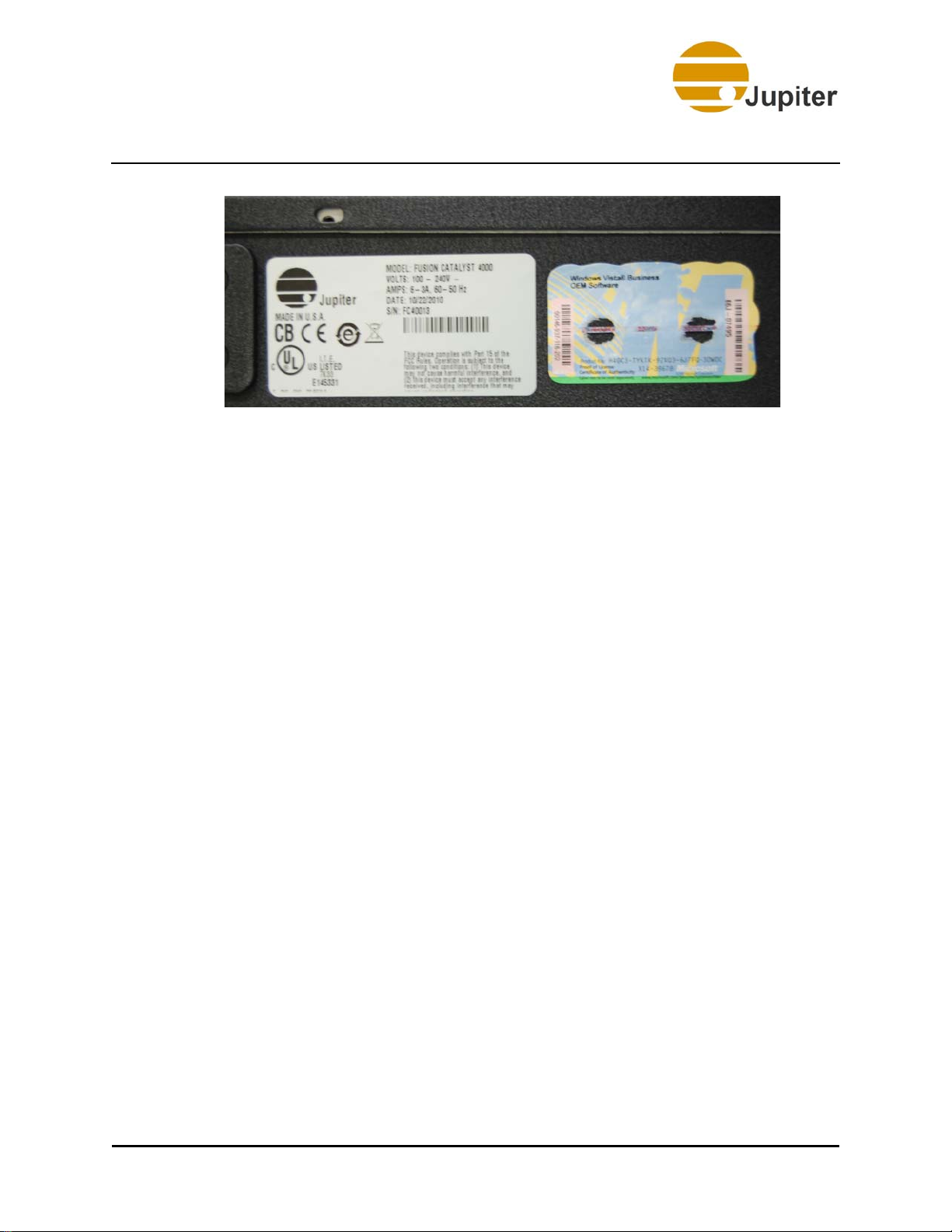
What’s in the Fusion Catalyst 4000 Box
Figure 1 - Serial and Windows Key Labels
Fusion Catalyst 4000 Getting Started Guide 7


Chapter 3—Hardware Setup
3. Hardware Setup
This section describes the hardware setup for the Fusion Catalyst 4000
Wall Controller.
3.1 Rack Mount
Mount the Fusion Catalyst System chassis in the 19-inch rack designated
for this system. Refer to the Fusion Catalyst 4000 Hardware Manual
for specific information on installing the chassis in the 19-inch rack. It is
recommended that you have two people working together to install the
Fusion chassis in the 19-inch rack assembly.
3.2 Connecting the System
The following sections describe how to connect the cables to the Fusion
Catalyst 4000 System. Refer to the sections referenced in the Fusion
Catalyst 4000 Hardware Manual for specific information on a hardware
component.
3.2.1 Fusion Catalyst 4000 Connections
1. Ensure that the power switch is off.
2. Connect the power cord to the rear of the Fusion Catalyst 4000
chassis.
3. Connect the keyboard and mouse to the USB ports of the Fusion
Catalyst 4000 chassis.
Fusion Catalyst 4000 Getting Started Guide 9

3—Hardware Setup
4. Connect the display cables to the proper graphics output
connectors on the rear of the system. Display devices in a wall
are numbered top left to bottom right counting across to the
right and moving down.
Figure 2 - Default Display Numbering, 3 x 3 Array
Figure 3 - Typical Fusion Catalyst 4000 Rear Chassis
10 Fusion Catalyst 4000 Getting Started Guide

Connecting the System
The following boards are Optional:
• Dual or Quad Channel Gigabit Ethernet Board
• Quad HD Decoder Board
• CatalystLink Board
• Sound Board
• RAID 5 Board
Caution Do not use the VGA port. Jupiter Systems does not support
it.
3.2.2 Fusion Catalyst 4000 Cable Connections
The Catalyst system outputs can be connected with either DVI-D cables or
analog (VGA) cables. If analog cables are used you will need to install the
adapters shown here.
Note Jupiter Systems does not ship the DVI-I to HD 15 Adapters
with Fusion Catalyst 4000.
Figure 4 - DVI-I to HD 15 Adapters
Catalyst output connectors are white. Cables must be connected in output
order. Graphics channels are labeled on the rear of the chassis. Output
channels correspond to display numbering in front view of the wall as
shown in Figure 13 - “Fusion Catalyst 4000 Connection Map” on
page 18.
Fusion Catalyst 4000 Getting Started Guide 11

3—Hardware Setup
Figure 5 - DVI Output Connections
The Catalyst system DVI input channels are numbered on the rear panel.
These channels correspond to the channel number selected in the
software. DVI inpu t connectors are blue.
Figure 6 - DVI-I Input Connections
12 Fusion Catalyst 4000 Getting Started Guide

Connecting the System
Warning To prevent shock or accidental static discharge, make sure
that the Fusion Catalyst and projectors are OFF and
properly grounded (connected to a three wire AC source)
before attempting to connect the analog or DVI cables
between the projectors and the Fusion Catalyst. Failure to
do this may result in damage to the graphics output
circuitry.
Note It is important to note that the Graphics Board, in
conjunction with the DVI-I Connectors, has output and
connections for BOTH digital DVI signals and analog VGA
signals. There is a 5 meter limit to the length of cables used
for digital output to digital monitors.
3.2.2.1 Power Connections
Install the power cord to the Fusion Catalyst. Plug the power cord into an
AC outlet.
3.2.2.2 Mouse and Keyboard Cables
Plug the mouse and keyboard cables into any one of the USB ports.
Fusion Catalyst 4000 Getting Started Guide 13

3—Hardware Setup
3.3 CatalystLink Input Board
The CatalystLink board provides additional input capability from PixelNet
nodes, including DVI-I, 3G SDI, and HD component nodes.
• Each CatalystLink card features 4 PixelNet ports and supports up
to 8 PixelNet Input nodes
• Supports 4 destination windows per card
Figure 7 - CatalystLink Input Board
14 Fusion Catalyst 4000 Getting Started Guide

Quad HD Decoder Board
3.4 Quad HD Decoder Board
The Quad HD Decoder board allows SD/HD encoded stream sources to be
brought into the system. The Quad HD Decoder board is a dedicated
hardware decoder that can decode four simultaneous SD/HD streams in
various encoded formats and transport method.
The Quad HD Decoder board consists of 4 RJ45 Ethernet connectors and
connection to the baseboard is a 4-lane Gen1 PCI Express. This board can
generate up to four windows on the wall, using one or more inputs, with
independent scaling possible on each window.
Figure 8 - Quad HD Decoder Board
Fusion Catalyst 4000 Getting Started Guide 15

3—Hardware Setup
3.5 Optional Octal Video Input Panel Connections
If the system includes the optional Octal Video Input Panel, connect the
panel to the appropriate Octal Video Board using the Octal Video Cable
(SCSI-type cable). This cable has yellow labels.
Each Input Panel supports up to two Octal Video Boards. The first Octal
Board (counted by the lowest chassis slot number) will be connected to the
left side of the Input Panel. The second board (next Octal Board in the
chassis) will be connected to the right side connector on the panel. Input
channels are counted from left to right (looking at the front of the panel).
Each BNC connector pair is labeled with an input number. The first set of 8
Octal Video inputs (left side) on the first Octal Video Input Panel are
labeled 1 to 8; the second set, if installed, will be labeled 9 to 16.
Each vertical pair of BNC connectors supports a single composite signal by
connecting a BNC cable to the upper connector (or a single S-video signal
by connecting the Luminance signal to the upper BNC connector) and the
Chrominance signal to the lower BNC connector (or by using an S-video to
dual BNC adapter).
Figure 9 - Octal Video Input Panel (8 inputs) – Front View
Figure 10 - Octal Video Input Panel (16 inputs) – Front View
16 Fusion Catalyst 4000 Getting Started Guide

Optional Octal Video Input Panel Connections
Figure 11 - Octal Video Input Panel – Rear View
Figure 12 - Octal Cable
Fusion Catalyst 4000 Getting Started Guide 17

3—Hardware Setup
Figure 13 - Fusion Catalyst 4000 Connection Map
18 Fusion Catalyst 4000 Getting Started Guide

Chapter 4—Configuring Network
4. Configuring Network
This section describes the various steps needed to configure the network
and connections in your Fusion Catalyst System. These steps usually only
have to be performed one time when the system is installed.
4.1 First Time Startup
Note It is recommended that you have a standard multi-sync
monitor (or flat panel) available for configuring your Wall
Controller for the first time. Your Wall Controller has been
configured at the factory for a single display and a
resolution of 1024x768 at 60 Hz refresh rate.
Power-on the Fusion Catalyst and wait for Windows to boot. The factory
has already entered the Windows Product ID; however, you will be
required to answer a few other questions for Windows. Note that you can
find your Product ID on the side of the chassis. You will need this Product
ID in order to complete the Windows installation if you re-install.
Fusion Catalyst 4000 Getting Started Guide 19

4—Configuring Network
4.2 Logging onto the System
The first time you enter the system, the desktop will appear without any
need to log in. It is recommended that you set up user accounts and
passwords appropriate to your installation and company security policies.
The factory has already setup a default user name, Jupiter. There is no
password. The default user name can be used by typing Jupiter and
pressing the Enter key.
Table 3: User Name and Password
Windows User Name Password
7 Jupiter (none)
4.3 Configuring the Fusion Catalyst System
This section covers configuring your Fusion Catalyst System.
4.3.1 Configuring the Network
Because your display controller has been completely installed at the
factory, only a few entries (listed below) will make the controller
operational on a network. If your network is setup for DHCP, you may w ant
to change the computer name (in the next section), then skip the network
configuration steps following that.
You are advised to contact your network administrator before configuring
the network parameters. If your system is not using DHCP, you will need to
have IP address, subnet mask, computer name, and workgroup names
ready when doing the Network Configuration. If you do not know how to
enter these parameters or do not have them available, please see your
network administrator.
20 Fusion Catalyst 4000 Getting Started Guide

Configuring the Fusion Catalyst System
4.3.2 Changing the Computer Name
Open Control PanelSystemChange Settings link.
Figure 14 - Change Settings link
Fusion Catalyst 4000 Getting Started Guide 21

4—Configuring Network
Enter a new name and click the Change button.
Figure 15 - Computer Name
Enter the information necessary for this system for a Computer Name on
your network.
22 Fusion Catalyst 4000 Getting Started Guide

Configuring the Fusion Catalyst System
Figure 16 - Changing the Computer Name
If your network is setup for DHCP, skip to Configuring the ControlPoint
Software.
Fusion Catalyst 4000 Getting Started Guide 23

4—Configuring Network
4.3.3 Setting Visual Effects
The following settings are required for optimal Fusion Catalyst
performance in Windows 7.
Steps to do the settings:
1. Open My Computer properties dialog.
2. Select Advanced System Settings. The System Properties
dialog appears as shown below.
Figure 17 - Advanced System Settings
3. Select the Advanced tab on the System Properties dialog.
24 Fusion Catalyst 4000 Getting Started Guide

Configuring the Fusion Catalyst System
4. Click on the Settings button in the Performance group. The
Performance Options dialog appears.
Figure 18 - Performance Options Dialog
5. Select the Visual Effects tab on the Performance Options
dialog.
6. Select the Adjust for best performance option to un-check the
entire list.
7. Select the Custom option.
Fusion Catalyst 4000 Getting Started Guide 25

4—Configuring Network
8. In the Custom item list, select (check) the following items, as
shown on figures below:
• Animate controls and elements inside windows
• Fade or slide menus into view
• Fade or slide ToolTips into view
• Fade out menu items after clicking
Figure 19 - Custom Items List
26 Fusion Catalyst 4000 Getting Started Guide

Configuring the Fusion Catalyst System
9. Scroll down on the list and select the following items:
• Smooth edges of screen fonts
• Smooth scroll list boxes
• Use visual styles on windows and buttons
Figure 20 - Custom Items List (continued)
10. Click Apply and then OK.
Fusion Catalyst 4000 Getting Started Guide 27

4—Configuring Network
4.3.4 Configuring the Connections
If your network is configured for DHCP, you should skip this section and
jump to the next section on configuring the ControlPoint software.
1. Open Network Connections (right click Network Places and
click Properties). Double-click the appropriate Local Area
Connection icon (or right click the network icon and click
Properties).
Figure 21 - Connections
28 Fusion Catalyst 4000 Getting Started Guide

Configuring the Fusion Catalyst System
2. Double-click the Local Area Connection icon to bring up the
dialog shown below.
Figure 22 - Local Area Connection
3. Click the Properties button to get to the dialog shown in the
following graphic.
4. Under the General tab, select Internet Protocol Version 4 (TCP/
IPv4) to highlight it as shown below. Then click the Properties
button.
Fusion Catalyst 4000 Getting Started Guide 29

4—Configuring Network
Figure 23 - Network Protocols
30 Fusion Catalyst 4000 Getting Started Guide

Configuring the Fusion Catalyst System
5. After clicking the Properties button, you will see the dialog
below. Set the IP Address and all other parameters appropriate
to your installation.
Figure 24 - TCP/IPV4 Properties
If you do obtain IP and DNS server addresses automatically from your
network, you will need to type in the proper addresses as shown in the
figure above. If you do not have a v alid address for your individual system
or you do not know what address your network uses, you will need to
contact your IT department or network administrator to get the proper
addresses. You will need to enter an IP addresses for each Ethernet
adapter installed in the Fusion Catalyst System.
Please be sure that you enter these numbers accurately. Your computer
may not operate properly on the network, if the required addresses are not
entered correctly. When done, click the OK button.
Fusion Catalyst 4000 Getting Started Guide 31

4—Configuring Network
a. Enter IP and DNS settings as required by your network.
Figure 25 - Advanced Settings
b. Close out and save all settings by clicking successive OK
buttons. Restart.
32 Fusion Catalyst 4000 Getting Started Guide

Chapter 5—ControlPoint Sof tware
5. ControlPoint Software
5.1 Configuring the ControlPoint Software
Your Display Wall can be configured with the VSConfig utility in a few
basic steps. These steps will be covered in detail in the following sections.
1. Configure the Display Devices (projectors, cubes, monitors, flat
panels); resolution, color depth, and frequency.
2. Configure the wall itself – the number of rows and the number of
displays in each row.
Cautions: 1. User Access Control (UAC) needs to be turned off to run
VSConfig.
2. Close ALL windows before making any changes to items
in VSConfig.
3. You must restart your Fusion Wall Controller system
TWICE whenever any changes are applied to the
VSConfig.
4. The Settings page within Display Settings will show
the VirtualScreen as Display 1. The graphics port on the
motherboard is shown as Display 2. The primary display for
the system must be Display 1. Do not enable Display 2!
Fusion Catalyst 4000 Getting Started Guide 33

5—ControlPoint Software
5.2 Virtual Screen Configuration
1. Run VSConfig: Go to Start Menu/Programs/Jupiter/
ControlPoint/VSConfig
Figure 26 - VSConfig Program
34 Fusion Catalyst 4000 Getting Started Guide

Virtual Screen Configuration
2. Set the wall dimension to 2x2 (i.e. set Screens Horizontally and
Screens Vertically fields to 2).
Figure 27 - Virtual Screen Configuration
3. Set the desired single screen resolution. In the following
example, it is: 1680 x 1050 x 32
4. Click OK. When prompted for restarting Windows, click Yes.
5. After Windows is restarted, it is necessary to restart Windows a
second time.
6. If the wall layout is reconfigured, the Single Screen Resolution
will go blank. In such cases, set the resolution and restart the
system.
Fusion Catalyst 4000 Getting Started Guide 35

5—ControlPoint Software
5.3 Verifying the Device Map
In order for your system to operate properly, the Device Map must
correctly describe your system. The following figure shows a
representation of the Device Map.
1. Open the Device Map by starting the VSConfig dialog.
2. Click the Device Map button.
Figure 28 - Device Map
The Device Map dialog appears, displaying a tree-list of the system
devices. If the dialog does not describe your system properly, go to the
Windows Device Manager and check that all Fusion Catalyst Devices are
correctly installed.
36 Fusion Catalyst 4000 Getting Started Guide

Index of Figures
Figure 1. Serial and Windows Key Labels . . . . . . . . . . . . . . . . . . . . . .7
Figure 2. Default Display Numbering, 3 x 3 Array . . . . . . . . . . . . . .10
Figure 3. Typical Fusion Catalyst 4000 Rear Chassis . . . . . . . . . . . .10
Figure 4. DVI-I to HD 15 Adapters . . . . . . . . . . . . . . . . . . . . . . . . . .11
Figure 5. DVI Output Connections . . . . . . . . . . . . . . . . . . . . . . . . . .12
Figure 6. DVI-I Input Connections . . . . . . . . . . . . . . . . . . . . . . . . . .12
Figure 7. CatalystLink Input Board . . . . . . . . . . . . . . . . . . . . . . . . . .14
Figure 8. Quad HD Decoder Board . . . . . . . . . . . . . . . . . . . . . . . . . .15
Figure 9. Octal Video Input Panel (8 inputs) – Front View . . . . . . .16
Index of Figures
Figure 10. Octal Video Input Panel (16 inputs) – Front View . . . . .16
Figure 11. Octal Video Input Panel – Rear View . . . . . . . . . . . . . . . . 17
Figure 12. Octal Cable . . . . . . . . . . . . . . . . . . . . . . . . . . . . . . . . . . . .17
Figure 13. Fusion Catalyst 4000 Connection Map . . . . . . . . . . . . . . .18
Figure 14. Change Settings link . . . . . . . . . . . . . . . . . . . . . . . . . . . .21
Figure 15. Computer Name . . . . . . . . . . . . . . . . . . . . . . . . . . . . . . . .22
Figure 16. Changing the Computer Name . . . . . . . . . . . . . . . . . . . . .23
Figure 17. Advanced System Settings . . . . . . . . . . . . . . . . . . . . . . .24
Figure 18. Performance Options Dialog . . . . . . . . . . . . . . . . . . . . . .25
Figure 19. Custom Items List . . . . . . . . . . . . . . . . . . . . . . . . . . . . . .26
Figure 20. Custom Items List (continued) . . . . . . . . . . . . . . . . . . . .27
Figure 21. Connections . . . . . . . . . . . . . . . . . . . . . . . . . . . . . . . . . . .28
Figure 22. Local Area Connection . . . . . . . . . . . . . . . . . . . . . . . . . . .29
Figure 23. Network Protocols . . . . . . . . . . . . . . . . . . . . . . . . . . . . . .30
Fusion Catalyst 4000 Getting Started Guide 37

Figures
Figure 24. TCP/IPV4 Properties . . . . . . . . . . . . . . . . . . . . . . . . . . . .31
Figure 25. Advanced Settings . . . . . . . . . . . . . . . . . . . . . . . . . . . . . .32
Figure 26. VSConfig Program . . . . . . . . . . . . . . . . . . . . . . . . . . . . . .34
Figure 27. Virtual Screen Configuration . . . . . . . . . . . . . . . . . . . . . .35
Figure 28. Device Map . . . . . . . . . . . . . . . . . . . . . . . . . . . . . . . . . . .36
38 Fusion Catalyst 4000 Getting Started Guide

Index of Tables
Table 1. Container Contents . . . . . . . . . . . . . . . . . . . . . . . . . . . . . . . . 6
Table 2. Accessory Tray Contents . . . . . . . . . . . . . . . . . . . . . . . . . . . . 6
Table 3. User Name and Password . . . . . . . . . . . . . . . . . . . . . . . . . .20
Index of Tables
Fusion Catalyst 4000 Getting Started Guide 39


Index
Index
A
Accessory Tray ............................6
Advanced Settings
System Properties ................... 24
B
Boards and Accessories
CatalystLink Board ................... 14
Quad HD Decoder Board ............ 15
C
Cable Connections ..................... 11
CatalystLink Board
Boards and Accessories ............. 14
Change Settings
Chassis
.......................................5
Configuring
Network Connections ................ 28
Connecting System
Connections
Container Contents
ControlPoint
Introduction .............................1
........................ 21
............................... 20
......................9
................................9
......................6
Copyright
................................... iii
Custom Settings
Visual Effects ..........................26
D
Device Map
Verifying ...............................36
Virtual Screen Configuration .......36
F
Fusion Catalyst 4000
Accessory Tray ..........................6
Cable Connections ...................11
Change Computer Name ............23
Change Settings ......................21
Configuring ............................20
Connecting System ....................9
Connections .............................9
Container Contents ....................6
First Time Startup ....................19
Logging On ............................20
Octal Video Connections ............16
Optional Boards .......................11
Power Connections ...................13
Rack Mount ..............................9
System Concepts .......................5
Fusion Catalyst 4000 Getting Started Guide 41

Index
H
Hardware Setup ...........................9
Hardware Warranty
...................... v
I
IP Settings
Advanced .............................. 32
TCP/IPV4 Properties ................. 31
L
License Agreement ......................vii
Local Area Connection Properties
Network Protocol ..................... 30
Local Area Connection Status
...... 29
N
Q
Quad HD Decoder Board
Boards and Accessories .............15
R
Rack Mount .................................9
S
Serial Key Label ...........................7
Setting Visual Effects
Single Screen Resolution
Virtual Screen Configuration .......35
Software Warranty
Starting
VSConfig ...............................34
System Concepts
System Properties
Advanced Settings ...................24
..................24
......................vi
.........................5
Network Connections
Configuring ............................ 28
Network Protocol
Local Area Connection Properties .30
O
Octal Video Connections ............. 16
P
Performance Options
Custom ................................. 26
Visual Effects .......................... 25
Custom Settings ................... 26
Power Connections
Product ID Number
..................... 13
......................7
T
TCP/IPV4 Properties
IP Settings .............................31
V
Verifying
Device Map ............................36
Virtual Screen Configuration
Device Map ............................36
Single Screen Resolution ...........35
Wall Dimension .......................35
Visual Effects
Custom Settings ......................26
Performance Options ................25
VSConfig
...................................33
42 Fusion Catalyst 4000 Getting Started Guide

Index
Starting ................................ 34
W
Wall Dimension
Virtual Screen Configuration ....... 35
Windows Key
..............................7
Fusion Catalyst 4000 Getting Started Guide 43

 Loading...