

Page 1
EX Series Redundant Power System Quick Start
See the complete RPS documentation at http://www.juniper.net/techpubs/ .
To install and configure a Juniper Networks EX Series Redundant Power Supply (RPS),
you need:
z Two mounting brackets and eight mounting screws for rack mounting (provided)
z One RPS cable per switch (one is provided, six is the maximum needed)
z At least one EX-PWR3-930-AC power supply (one provided in a separate box)
z Electrostatic discharge (ESD) grounding strap (not provided)
z Phillips (+) screwdriver, number 1 (not provided)
z Screws to secure the chassis to the rack or cabinet (not provided)
Part 1: Mount the RPS in a Rack
Installing the RPS requires one person to lift the switch and a second person to secure it
to the rack. Mount an RPS on two posts of a 19-in. rack or cabinet by using the mounting
brackets provided with the switch. You can also mount an RPS on four posts of a 19-in.
rack or cabinet by using the separately orderable four-post rack-mount kit. There is no
traditional front and back on an RPS. You can position either the switch connector side or
the power supply side of the RPS at the front of the rack.
Part 2: Install Power Supplies
Install one, two, or three power supplies. Install the first one in the center slot.
1. Remove the cover from an RPS power supply slot---use the center slot first.
NOTE: RPS will not power up if the center power supply is not installed first.
2. Use the screwdriver to loosen the locking lever screw on the power supply.
3. Push down on the locking lever until it is in its lowest position.
4. Using both hands, slide the power supply into th e un co ve re d po w er supply slot.
5. Push the locking lever up to its highest position.
6. Using the screwdriver, tighten the locking lever screw.
Each power supply can provide backup power for one switch, with a maximum of three
switches concurrently supported by three power supplies.
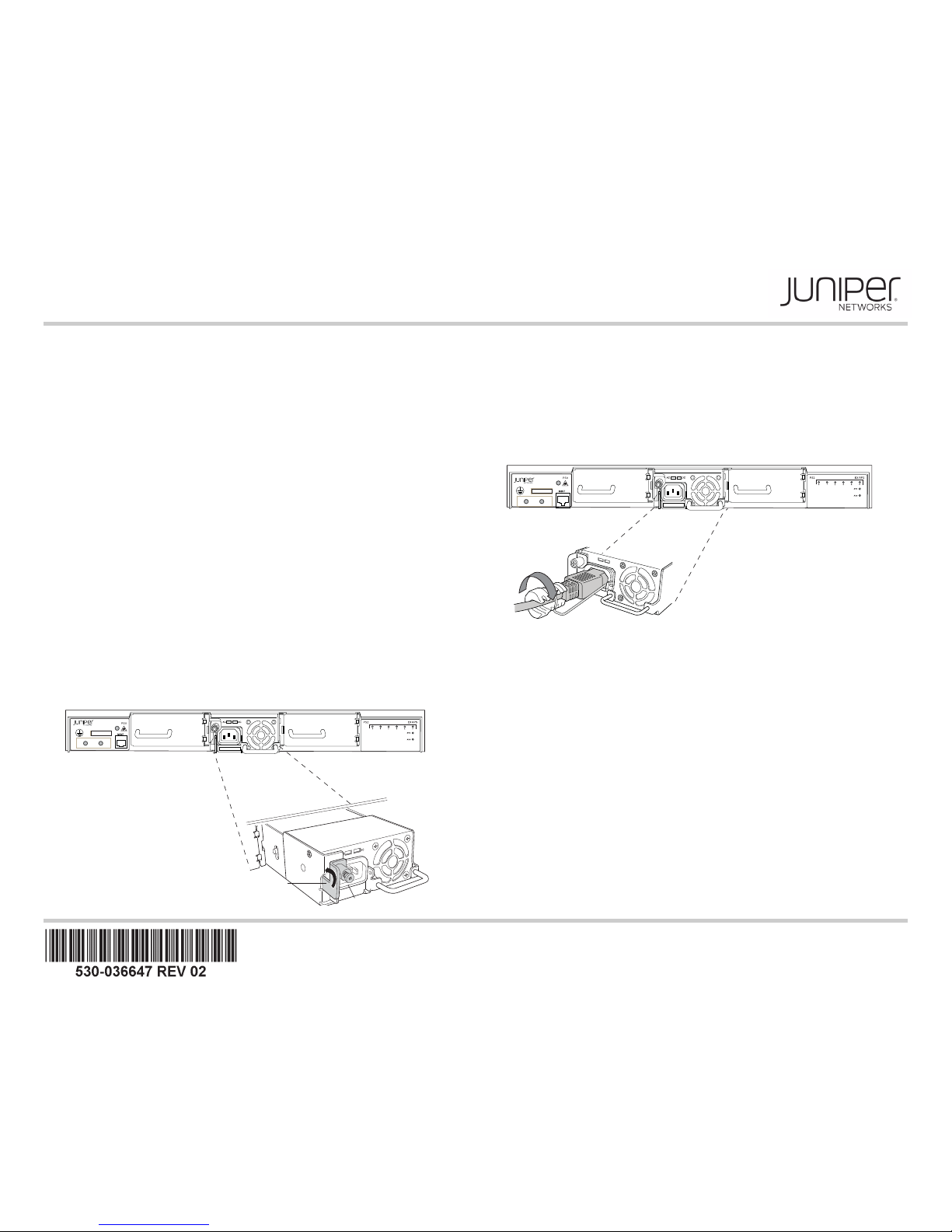
Part 3: Connect AC Power to Each Power Supply
1. Squeeze the two sides of the power cord retainer clip and insert the L-shaped ends of
the wire clip into the holes in the bracket on each side of the AC appliance inlet.
2. Insert the coupler end of the power cord into the AC appliance inlet.
3. Push the cord into the slot in the adjustment nut of the power cord retainer. Turn the
nut until it is snug against the base of the coupler and the slot in the nut is turned 90°
from the top of the switch.
4. If the AC power source outlet has a power switch, set it to the OFF (0) position.
5. Plug the power cord into the power source outlet.
6. If the AC power source outlet has a power switch, set it to the ON (|) position.
The RPS powers up as soon as the first power supply is installed in the center slot. Install
up to two additional power supplies with the power on (hot-swap)---be sure to connect a
power cord to each power supply.
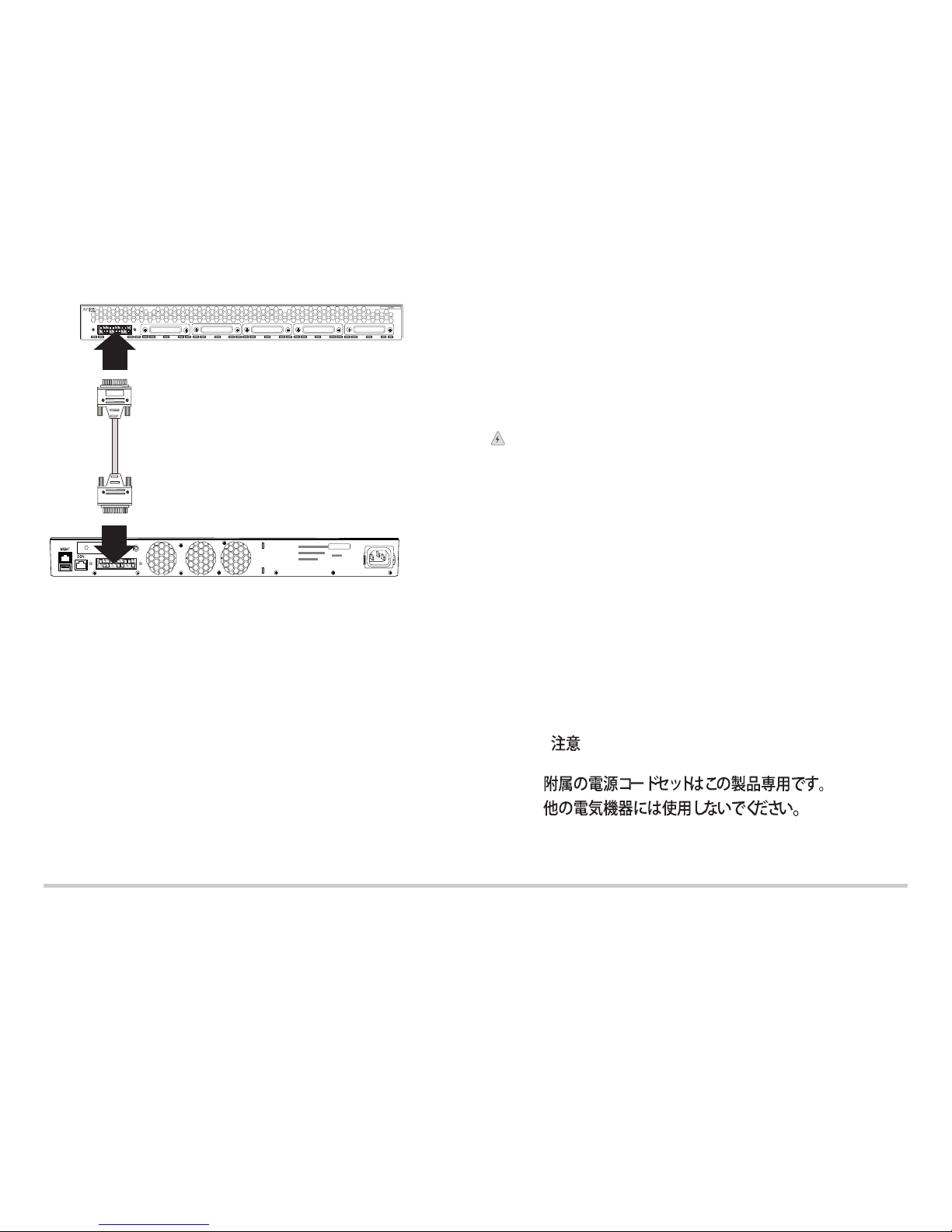
Part 4: Connect Each Supported Switch to the RPS
Each configured switch has a priority assigned to it when you connect it to the RPS.
Those priority values determine which switches receive power from the RPS first. Priority
is determined by connector position. By default, looking at the connectors, the leftmost
connector has lowest priority and the rightmost one has highest priority. Position your
switches accordingly. (You can also configure switch priority from switches---see
Optionally Override Default RPS Priority Configuration on the next page.)
1. Attach the ESD grounding strap to your bare wrist and to the ESD point on the RPS
chassis.
2. If the RPS connector on the switch is covered with a panel, remove the cover panel.
3. Connect the RPS cable to a powered switch.
Locking lever
g021300
Tighten captive screw.
Tighten
adjustment nut.
AC
DC
g021301
Page 2
Juniper Networks, Junos, Steel-Belted Radius, NetScreen, and ScreenOS are registered trademarks of Juniper Networks, Inc. in the United States and other countries. The Juniper Networks Logo, the Junos logo, and JunosE are
trademarks of Juniper Networks, Inc. All other trademarks, service marks, registered trademarks, or registered service marks are the property of their respective owners. Junip er Networks assumes no responsibility for any inaccuracies
in this document. Juniper Networks reserves the right to change, modify, transfer, or otherwise revise this publication without notice. Products made or sold by Juniper Netw orks or components thereof might be covered by one or more
of the following patents that are owned by or licensed to Juniper Networks: U.S. Patent Nos. 5,473,599, 5,905,725, 5,909,440, 6,192,051, 6,333,650, 6,359,479, 6,406,312, 6,429, 706, 6,459,579, 6,493,347, 6,538,518, 6,538,899,
6,552,918, 6,567,902, 6,578,186, and 6,590,785. Copyright © 2012, Juniper Networks, Inc. All rights reserved. Printed in USA. Part Number: 530-036647, rev 02, March 2012.
4. If the RPS connector on the RPS chassis has a cover on it, remove the cover panel.
5. Connect the cable to the uncovered RPS connector. The RPS software starts
configuring a connection as soon as both sides of the cable are connected.
6. After a minute, verify connection status. The Status LED corresponding to the
connector should be lit. The LED can be steady (connected), blinking (supplying
power), or off (no connection).
7. Connect up to five more switches.
NOTE: You can also determine connection status by issuing the show
redundant-power-system led command on the switch.
Installation is Complete
Your RPS is now installed and capable of providing either PoE or non-PoE backup power
to one attached switch per power supply. You can check RPS status from any connected
switch using the command show chassis redundant-power-supply.
Part 5: Optionally Reconfigure Switch Priority
You can override the default RPS switch priority by configuring RPS priority on the
switches. For directions on changing switch priority, see the redundant-power-system
priority command in the Complete Guide for the EX Series Redundant Power System.
Part 6: Optionally Configure Power to Support Only Non-PoE Switches
If you don’t need to support PoE, your RPS can provide power to up to six connected
switches simultaneously (two per power supply). For directions on changing the power
setting, see the request-redundant-power-system multi-backup command in the
Complete Guide for the EX Series Redundant Power System.
Safety Warnings Summary
This is a summary of safety warnings. For a complete list of warnings, including
translations, see the Complete Guide for the Redundant Power System at
http://www.juniper.net/techpubs/ .
WARNING: Failure to observe these safety warnings can result in personal injury or
death.
z Permit only trained and qualified personnel to install or replace RPS components.
z Perform only the procedures described in this guide and the EX Series documentation.
Other services must be performed only by authorized service personnel.
z Before installing the RPS, read the planning instructions in the documentation to make
sure that the site meets power, environmental, and clearance requirements.
z Before connecting a RPS to a power source, read the installation instructions in the
documentation.
z Installing an RPS requires one person to lift the switch and a second person to install
mounting screws.
z If the rack has stabilizing devices, install them in the rack before mounting or servicing
the RPS in the rack.
z Before installing or after removing an electrical component, always place it
component-side up on an antistatic mat placed on a flat, stable surface or in an
antistatic bag.
z Do not work on the RPS or connect or disconnect cables during electrical storms.
z Before working on equipment that is connected to power lines, remove jewelry,
including rings, necklaces, and watches. Metal objects heat up when connected to
power and ground and can cause serious burns or become welded to the terminals.
Power Cable Warning (Japanese)
The power cable is only for this product. Do not use this cable for another product.
Contacting Juniper Networks
For technical support, see http://www.juniper.net/support/requesting-support.html .
EX2200-24-4G REV: X1
750-026464 REV: X3
MAC: 00:23:9C:oE:19:00
Mfg. Date
20090227
MADE IN CHINA
g021302
RPS
g040300
 Loading...