

Page 1

954122-000 EN/SV A0
OPERATING MANUAL/
ANVÄNDARMANUAL
JUPITER
Era 100/150J
FSK16
Page 2

Revision History
Version Date Reason
A0 2017-02-23
1st released version
Page 3

MANUAL LANGUAGES 3 (36)
Jupiter Era 100J & 150J (FSK16) Document-ID: 954122-000 EN/SV
Version: A0 Author: SH
EN
SV
MANUAL LANGUAGES
Operating Manual JUPITER Era 100/150J 4
Tandem and multi-operator operation (Only Era 150J) 14
Användarmanual JUPITER Era 100/150J 16
Tandem- och erförardrift
(endast Era 150J) 26
Transmitter overview JUPITER Era 100/150J 28
Layout JUPITER Era 100J & 150J Nordic symbols 29
Layout JUPITER Era 100J & 150J DIN symbols 30
Layout JUPITER Era 100J & 150J CS symbols 31
Symbol explanation / Symbolförklaring 32
Page 4

Operating Manual JUPITER Era 100/150J 4 (36)
Jupiter Era 100J & 150J (FSK16) Document-ID: 954122-000 EN/SV
Version: A0 Author: SH
EN
OPERATING MANUAL JUPITER ERA 100/150J
!
The equipment has to be controlled by a qualied operator
1 MAINTENANCE
To maintain availability and operational safety, a regular maintenance is
necessary on the system.
Daily Maintenance
Before each use of the transmitter, check the following items for faults or damages:
• Visual inspection of rubber sealing around levers
• Broken/faulty switches or controls
• Visual inspection of transmitter housing (cracks, dents)
• Visual inspection of carrying device
• Visual inspection of battery (cracks, dents)
• Test that the battery lock is functioning normally
• Test of safety stop button (it shall be intact and easy to move)
Check function of:
• Check function of transmitter status indicator, continious yellow at power up
If there is any damage or fault contact an authorised service technician.
Weekly Maintenance
• Clean the battery contacts and the contacts on the transmitter and charger
• Clean the transmitters control panel and check that the print is still readable
!
For cleaning use a dry cleaning cloth, if necessary use a wet cleaning cloth
and a soap solution. Never use an alcohol-based product for cleaning;
it can seriously damage the plastic.
Page 5
Operating Manual JUPITER Era 100/150J 5 (36)
Jupiter Era 100J & 150J (FSK16) Document-ID: 954122-000 EN/SV
Version: A0 Author: SH
EN
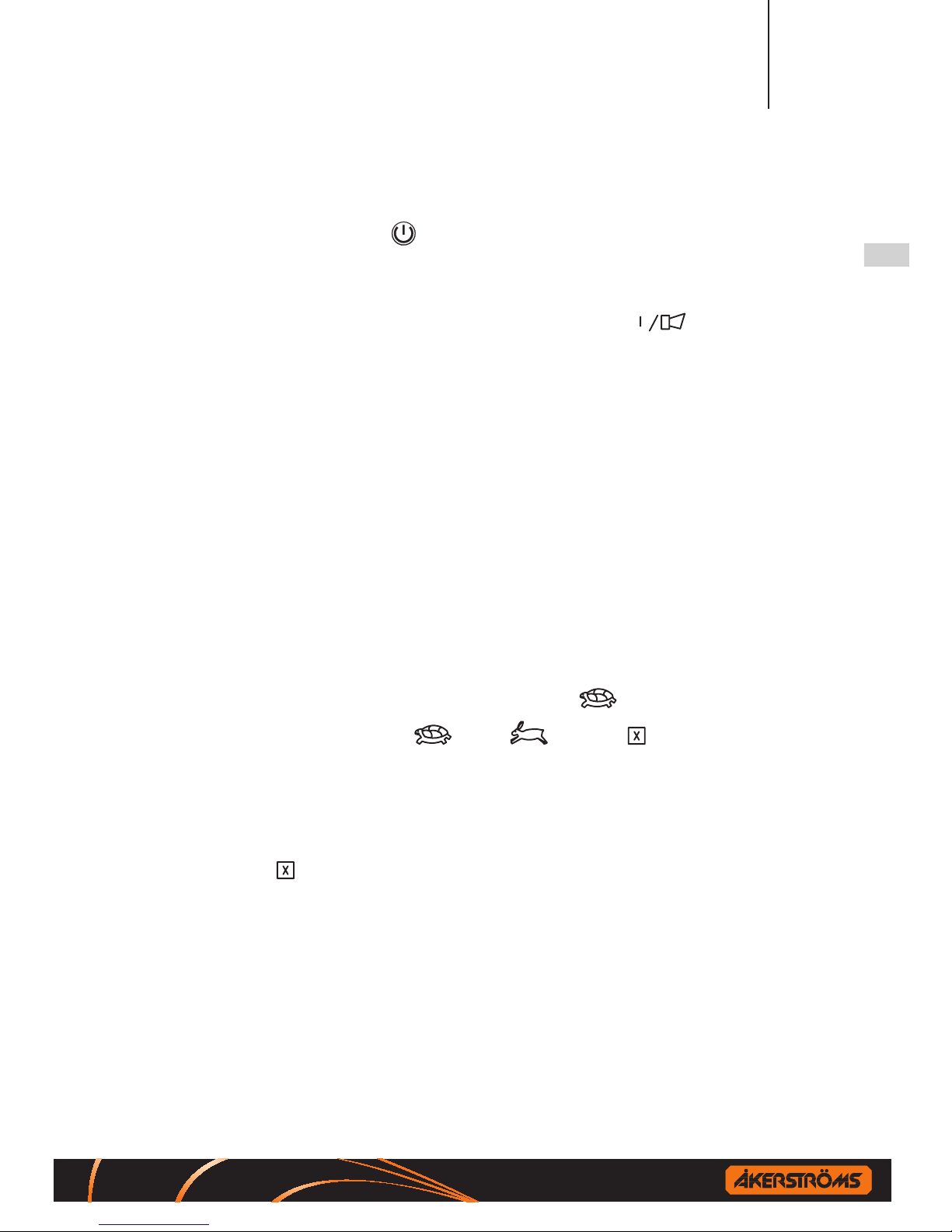
2 START THE TRANSMITTER & ACTIVATE THE MAIN CONTACTOR
Press the on/o button (note that the safety STOP button must be pulled
out), the transmitter makes a self-test for 5 seconds. The status indicator
(BAT) starts blinking, the transmitter has been activated.
When the transmitter is activated, press down button . This will activate
the main contactors in the receiver and in turn the main contactor of the crane.
The system is now ready for operation.
3 NORMAL OPERATION
The transmitter is designed with two joysticks:
One for Bridge/Trolley travel and the other for Hoist motions, each direction
being divided into 2 steps (a perceptible resistance) which facilitates the running at a certain speed. The size and direction of the joysticks movements are
equal to the speed and direction of the objects motions. Bridge and Trolley
can be run simultaneously with the same joystick. The motion stops when the
joystick is brought to neutral, if not depress the safety STOP button.
4 SLOW SPEED (MICRO) OPERATION
Set the selector switch for
-
Slow/ -Normal/ -Extra in position Slow.
The objects motion will now only operate at a factory pre-set slow speed regardless of the movements of the joystick. The joystick movements are also
interlocked during this time so that only one movement can be operated at a time.
5 EXTRA
This is an optional feature that can be activated in addition to the normal functions. The function is obtained immediately when the toggle switch is actuated
in position. The normal functions are not aected.
Page 6
Operating Manual JUPITER Era 100/150J 6 (36)
Jupiter Era 100J & 150J (FSK16) Document-ID: 954122-000 EN/SV
Version: A0 Author: SH
EN
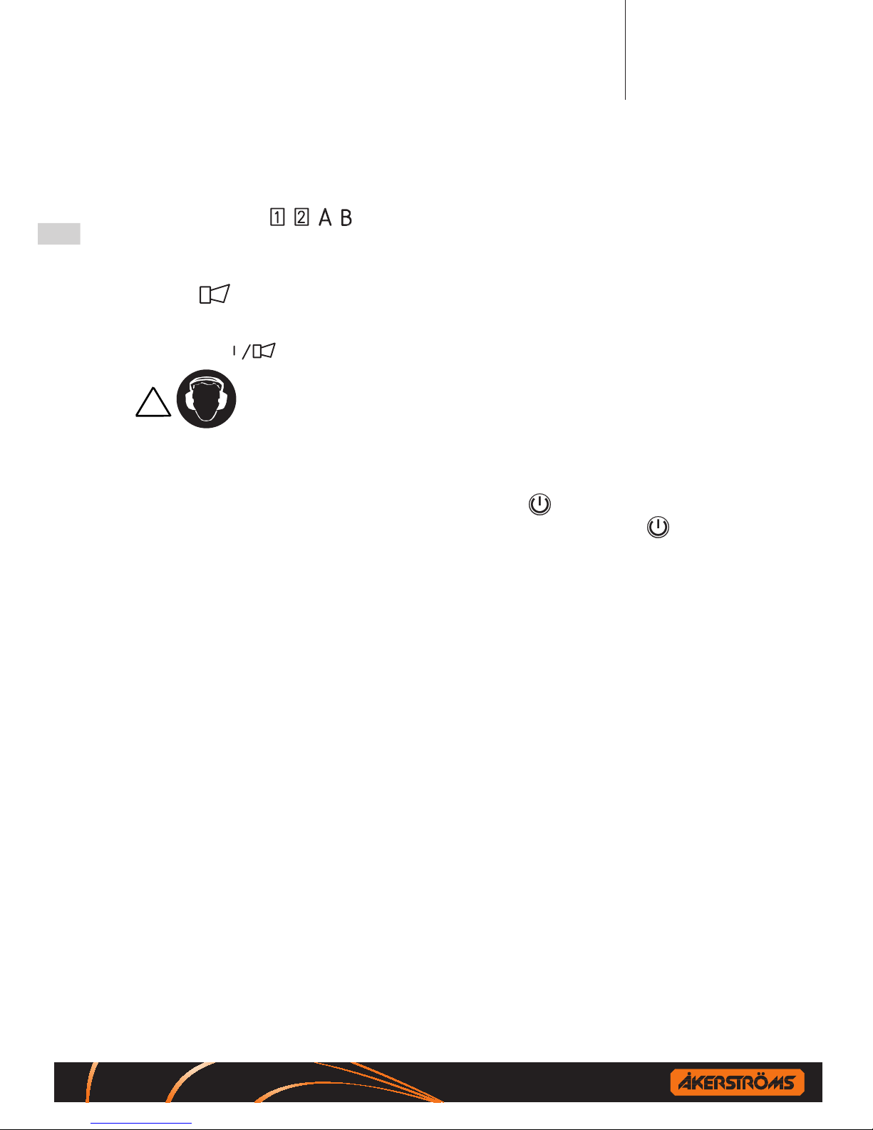
6 SELECTION 1, 2, A, B OR 1+2+A+B (Era 150J only)
Set toggle switch / / / to ON (1) for selection 1/2/A/B.
For deselecting, reset the corresponding switch to OFF (0).
7 SIREN
A signal can be emitted at any time during the run and sounds as long as the
push button is depressed.
Risk of high sound level, hearing protection required.
8 TRANSMITTER & MAIN CONTACTOR OFF
To deactivate the MC press down the on/o button once time quickly. To
turn o the transmitter press down an hold down the on/o button which
switches o the transmitter, and also the main contactor in the receiver is
deactivated (the main contactor of the crane gets de-energised). The status
indicator light goes out.
9 STOP (EMERGENCY)
Depress the safety STOP button for stop.
10 AUTOMATIC SWITCH-OFF FUNCTION
The transmitter is equipped with an automatic switch-o function, switching
o transmitter after 2, 5, or 15 minutes after the latest use. It is also possible
to set the transmitter for continuous operation. The status indicator for opera-
tion goes out and the main contactor is deactivated upon automatic switch-o.
See the installation manual for instruction how to set the automatic switch-o
time. For renewed activation of the main contactor a restart is required. Low
battery voltage also causes automatic switch-o.
Page 7
Operating Manual JUPITER Era 100/150J 7 (36)
Jupiter Era 100J & 150J (FSK16) Document-ID: 954122-000 EN/SV
Version: A0 Author: SH
EN
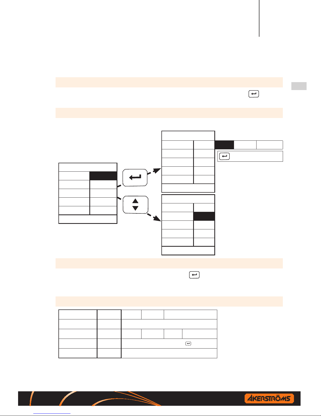
11 CONFIGURATION FROM DISPLAY
Enter User conguration menu:
When the transmitter is started press and hold down the enter button ( ),
approx. 2 seconds.
Menu navigation:
Whenenteringthecongurationmenuthetoprowselectionishighlighted.
(1/4) User Cong.
Auto-o 2 min
Power save On
Brightness 100%
LCD contrast 10
Font size Small
Exit
(1/4) User Cong.
Auto-o 2 min 5 min 15 min O
Power save On
Brightness 100%
LCD contrast 10
Font size Small
Exit
(1/4) User Cong.
Auto-o 2 min
Power save On
Brightness 100%
LCD contrast 10
Font size Small
Exit
Edit/toggle
row
Next row
Toggle selection
Exit/Save:
When the exit button is highlighted press enter toexittheconguration
menu.Thereisalsoanautomaticallyexitfromthecongurationmenuafter
10 seconds of inactivity.
Choices:
Auto-o 2 min 5 min 15 min O
Power save O On
Brightness O 25 % 50 % 75 % 100%
LCD contrast 10 0-20, one step with enter
button
Font size Small Large
Page 8
Operating Manual JUPITER Era 100/150J 8 (36)
Jupiter Era 100J & 150J (FSK16) Document-ID: 954122-000 EN/SV
Version: A0 Author: SH
EN
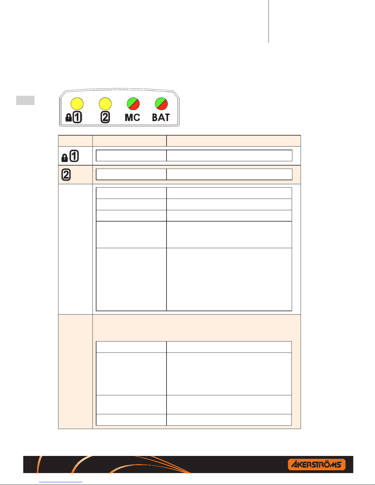
12 INDICATIONS
LED Indications Explanations
Yellow continuous When digital input 1 active
Yellow continuous When digital input 2 active
MC
OFF No link established
Greenashing Link established; Main Contactor OFF
Green continuous Link established; Main Contactor is ON
Yellow continuous Movements disabled due to tilting of the
transmitter (if enabled).
Main Contactor is ON
Red continuous Main Contactor locked
MC can not be activated due to one of
the following reasons:
-Safety STOP button depressed
-Tilt alarm
-Joystick not centered
-Congurationmenu/modeactive
BAT If the transmitter during start up or operation detect a fault in any of
the transmitters self-tests the status indicator will indicate continuously red light, after that the transmitter will shut down.
Greenashing Operating OK
Yellowashing Low Battery voltage
Operation can continue approximately 30
minutes depending on battery condition.
A prompt change of battery is recommended.
Yellow continuous Battery empty
Transmitterwillshut-o
Red continuous Hardware fault
Page 9
Operating Manual JUPITER Era 100/150J 9 (36)
Jupiter Era 100J & 150J (FSK16) Document-ID: 954122-000 EN/SV
Version: A0 Author: SH
EN
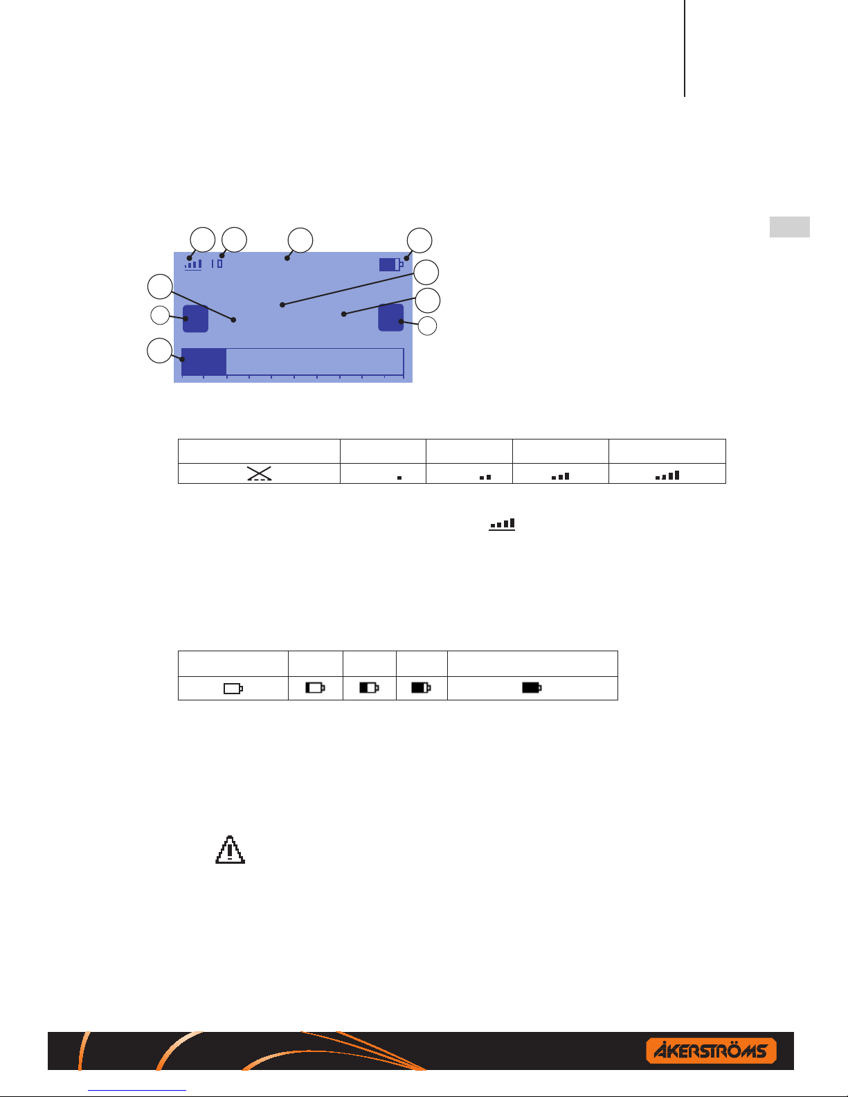
12.1 Display indications
Crane 1
14.1kg
1
2
8
1
3
7
4
6
5
9
9
2
1. Radio signal / Main contactor indicator
2. Channel indicator, up to 3 digits
(if the region setting is “Other” an “E” is displayed after
the channel number)
3. Text eld (crane id etc.)
4. Battery level
5. Weight, up to 5 digits
6. Weight unit (kg,t or lb)
7. Weight load graph (full-scale=max load)
8. Overload warning
9. Status indicator for digital input 1 and 2 on the
receiver
Radio signal quality
No radio link established Weak signal Good signal Strong signal Very strong signal
At low power mode the rst bar is narrower. MC on is indicated by a line
beneath the radio signal symbol, example .
Text eld (crane id etc.)
This text is congured in the receiver (8 characters). Informs the operator
which crane the transmitter is controlling.
Battery level
Battery empty 25% 50% 75% 100% (fully charged)
Weight / Graph / Overload
The weight is shown with the unit symbol kg, ton or lb. depending on the
receiver conguration. The bar graph displays the weight load. Full scale=
maximum load. The graph is only shown if a maximum weight limit is congured in the receiver.
This symbol appears if the load on the crane reaches the weight limit
(overload).
STOP
When the safety stop button is depressed the entire display turns red and an
STOP-sign is shown on the display
Page 10
Operating Manual JUPITER Era 100/150J 10 (36)
Jupiter Era 100J & 150J (FSK16) Document-ID: 954122-000 EN/SV
Version: A0 Author: SH
EN
13 BATTERY
The transmitter is equipped with a status indicator showing battery status.
The indicator blinks slowly green when the battery voltage is normal, but
starts to blink rapidly yellow, when it gets low. When the indicator has started
blinking rapidly yellow, the transmitter can be operated for approximately
15-30 minutes before the voltage is so low that the transmitter switches o
automatically.
Disposal of a Li-Ion battery poses a smaller threat to the environment when compared to other battery types. All used Li-Ion bat-
teries should be immediately sent to a qualied battery collection
centre for recycling.
• Removethebatteryfromthechargerwhenthepowersupplyisturnedo
• A well maintained battery is necessary for faultless operation.
!
The battery must not be charged if the temperature is lower than
+10ºC or higher than +45ºC.
!
Only use chargers approved by Åkerströms.
Warning! If an incorrect battery type is used in the unit,
the battery may explode.
Exchange battery:
13.1 CHARGING INSTRUCTIONS
Please read the documentation supplied with the charger for charging instructions.
Page 11
Operating Manual JUPITER Era 100/150J 11 (36)
Jupiter Era 100J & 150J (FSK16) Document-ID: 954122-000 EN/SV
Version: A0 Author: SH
EN
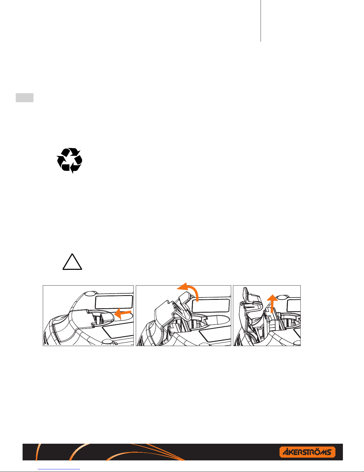
14 CIM CARD
The CIM card is used for storing conguration information. You can take out
the CIM-module from one system and place it in a spare transmitter with the
same system program and it will work exactly the same. This exchange has to
be done in a clean, dry and ESD safe environment.
!
To avoid personal and/or property damages; exchange CIM card ONLY
when the transmitter battery has been removed.
14.1 Removing/mounting CIM card
Disassembled
4
5
1
2
3
Assembled
1. Remove the battery.
2. Unscrew the bottom of the transmitter; pull up the bottom of the transmitter carefully.
Disassemble the mounting screw 1 for the CIM card 2.
3. Assemble the CIM card primarily in the original transmitter, alternative spare transmitter,
on the CIM card contact 3.
4. Tighten the mounting screw 1 including washer 4 and nylon distance 5 with 1 Nm.
5. Remount the bottom enclosure, check position of rubber seal. Tighten the screws with
1 Nm.
6. Insert battery. Now, the transmitter is ready for operation.
Page 12

Operating Manual JUPITER Era 100/150J 12 (36)
Jupiter Era 100J & 150J (FSK16) Document-ID: 954122-000 EN/SV
Version: A0 Author: SH
EN
15 INSTRUCTIONS FOR CRANE OPERATORS
These instructions have to be followed.
Check that the radio transmitter operates on the crane that you are going to
operate (ex. give a signal). Check all functions of the radio transmitter.
Check that no unauthorized person is on or near the crane when you start to
operate it. Any blocking device at the entry of the crane should be closed.
Check the position of the symbols for operating direction (crane-trolley-
travel).
At the beginning of each shift the crane operator is to test all brakes, limit
switches and emergency stop functions as well as the STOP button on the
transmitter.
The crane operator should when operating the crane stand at a suitable
distance from the crane hoist in order to have adequate overview of the
operation.
It is prohibited to move the crane load over oneself or coworkers. Signal in
order to warn others.
Avoid driving into end stops since equipment and goods can be damaged.
Check your own free passageway in order to avoid tripping over material
on the ground when you operate the crane. Keep the workplace in good
order.
If you loose control of the crane movements, release the joysticks to obtain
the zero position in order to stop the crane. If the crane still does not stop,
actuate the STOP function.
Page 13

Operating Manual JUPITER Era 100/150J 13 (36)
Jupiter Era 100J & 150J (FSK16) Document-ID: 954122-000 EN/SV
Version: A0 Author: SH
EN
Find out where the crane’s main power disconnect is, in order to be able to
quickly switch o if required.
Never hand over the transmitter to anyone who has not undergone training
in radio-control crane operation.
After completed operation you should always switch o the transmitter or
depress the STOP button.
Note! Never put the transmitter aside without rst activating the STOP or
switching the transmitter o.
The main contactor of the crane is to be switched o after the end of work-
ing hours. The transmitter is then to be kept inaccessible to unauthorized
persons.
In case of faults or breakdowns in the radio control equipment the crane
should permit operation from the cab or with suspended operating gear. In
such case rst turn the switch from radio operation to manual operation.
Make certain how this switch-over is to be made before you start operating
the crane.
Make sure that the receiver can not be activated when you service the
transmitter.
When working on the crane ensure that all radio transmitters
and other controls are locked or otherwise under supervision.
ALWAYS REPORT DEFECTS TO THE WORKPLACE MANAGEMENT.
Page 14

Tandem and multi-operator operation (Only Era 150J) 14 (36)
Jupiter Era 100J & 150J (FSK16) Document-ID: 954122-000 EN/SV
Version: A0 Author: SH
EN
TANDEM AND MULTI-OPERATOR OPERATION
(Only Era 150J)
16 TANDEM OPERATION
Tandem operation means that two cranes can be operated from the same transmitter, which makes it easier, for example to lift two objects simultaneously
or a big object using two cranes. The function of the transmitter for tandem
operation is dierent from the standard.
17 MULTI-OPERATOR OPERATION
Multi-operator operation means that two transmitters can operate the same
object. This can be benecial, for example, when the view is blocked. The
control of the object can be passed between two transmitters. Active crane
selection and deselection guarantees that only one transmitter is in control of
the object at a time. The function of the transmitter for multi-driver operation
is dierent from the standard.
18 START THE TRANSMITTER & ACTIVATE MC
The following procedure has to be followed when starting the transmitter:
1. Make sure no joysticks are moved.
2. Presstheon/obutton (note that the safety STOP button must
be pulled out).
3. The status indicator should show slow blinking green.
4. Check that the crane/cranes are free to operate.
5. Selectcrane/s.Thersttransmitterthatmaketheselectioncanoperate
the crane/s and the other transmitter will automatically be blocked.
6. Activate the main contactor (MC) in the receiver by push down the
button.
The unit is now in operating mode.
Page 15

Tandem and multi-operator operation (Only Era 150J) 15 (36)
Jupiter Era 100J & 150J (FSK16) Document-ID: 954122-000 EN/SV
Version: A0 Author: SH
EN
19 TRANSMITTER & MAIN CONTACTOR OFF
Deselect the crane/cranes before the transmitter is turned o, otherwise the
transmitter remains to block the crane/s selection.
To deactivate the MC press down the on/o button once time quickly. To
turn o the transmitter press down an hold down the on/o button which
switches o the transmitter, and also the main contactor in the receiver is
deactivated (the main contactor of the crane gets de-energised). The status
indicator light goes out.
20 SELECT CRANE DURING OPERATION
1. Check that the crane/cranes are free to operate.
2. Selectcrane/s.Thersttransmitterthatmaketheselectioncan
operate the crane/s and the other transmitter will automatically be
blocked.
3. Push down the button.
20.1 Selections
Set the toggle switch in desired position for trolley selection Trolley 1,
Trolley 2 or Trolley 1+2. Set the toggle switch in desired position for crane
selection Crane A, Crane B or Crane A+B.
Selection 1 1
Selection 2 2
Selection A
Selection B
Page 16

Användarmanual JUPITER Era 100/150J 16 (36)
Jupiter Era 100J & 150J (FSK16) Document-ID: 954122-000 EN/SV
Version: A0 Author: SH
SV
ANVÄNDARMANUAL JUPITER Era 100/150J
!
Utrustningen får endast manövreras av kvalicerad operatör
1 UNDERHÅLL
För att upprätthålla tillgängligheten och driftsäkerheten är ett regelbundet
underhåll nödvändig på systemet.
Dagligt underhåll
Före varje användning av sändaren, kontrollera följande för fel eller skador:
• Visuell inspektion av gummitätningen runt spakarna.
• Trasiga/felaktiga switchar eller kontroller
• Visuell inspektion av sändarkapslingen (sprickor, bulor)
• Visuell inspektion av bäranordningen
• Visuell inspektion av batteri (sprickor, bulor)
• Testa att batterilåset fungerar normalt
• Testa STOPP-knappen (den skall vara intakt och lätt att aktivera)
Kontrollera funktion av:
• Kontrollera sändarens status lysdiod, gul vid start.
Om det nns några skador eller fel kontakta auktoriserad servicetekniker.
Veckovist underhåll
• Rengör batteriets kontakter samt kontakterna på sändaren och laddaren
• Rengör sändarens kontrollpanel och kontrollera att trycket fortfarande är läsbart
!
För rengöring använd en torr rengöringsduk, om nödvändigt använd en
våt rengöringsduk och tvållösning. Använd aldrig en alkohol-baserad
produkt för rengöring, det kan allvarligt skada plasten.
Page 17

Användarmanual JUPITER Era 100/150J 17 (36)
Jupiter Era 100J & 150J (FSK16) Document-ID: 954122-000 EN/SV
Version: A0 Author: SH
SV
2 STARTA SÄNDARE & AKTIVERA HUVUDKONTAKTOR
Tryck på on/o knappen (obs. STOPP-knappen måste vara utdragen),
sändaren gör ett självtest i 5 sekunder. Därefter börjar statusindikeringen
(BAT) för drift att blinka grönt, sändaren har startats.
Huvudkontaktorn kan aktiveras efter att sändaren har startats. Tryck på knappen
så aktiveras huvudkontaktorn i mottagaren och systemet är klart för drift.
3 NORMAL KÖRNING
Sändaren har två joystickar:
En för Kranåk/Trallåk och en för Lyftrörelser. Varje riktning är uppdelad i
2 steg (ett kännbart motstånd) som underlättar körning i en viss hastighet.
Joysticksutslagets storlek och riktning svarar mot objektets hastighet och rörelseriktning. Kranåk och Trallåk kan köras samtidigt i samma joystick. Rörelserna stannar när joysticken förs till neutralläget, om inte tryck in STOPPknappen.
4 LÅGFARTS (MICRO) KÖRNING
Ställ vippströmbrytaren för Lågfart / Normal / Extra i Lågfartsläge.
Objektets rörelse går nu i en förinställd långsam fart oberoende av joystickens
utslag. Övriga funktioner verkar som vid normalkörning. Joystickens rörelser
är förreglade så att endast en rörelse kan manövreras åt gången, icke simultan.
5 EXTRA
Detta är en valbar funktion som kan aktiveras utöver de normala funktionerna.
Funktionen erhålls omedelbart när switchen ställs i detta läge, de normala
funktionerna påverkas inte.
Page 18

Användarmanual JUPITER Era 100/150J 18 (36)
Jupiter Era 100J & 150J (FSK16) Document-ID: 954122-000 EN/SV
Version: A0 Author: SH
SV
6 VAL 1, 2, A, B ELLER 1+2+A+B (endast Era 150J)
Sätt vippströmbrytaren / / / till ON (1) för val 1/2/A/B.
Då valet inte längre önskas sätt motsvarande vippströmbrytare i läge OFF (0).
7 SIREN
Signal kan ges när som helst under körningen och ljuder så länge signalknappen är intryckt.
Risk för hörselskador, använd hörselskydd.
8 STÄNG AV SÄNDARE & AVAKTIVERA HUVUDKONTAKTOR
För att avaktivera HK (MC), tryck in on/o knappen snabbt en gång. För
att stänga av sändaren, tryck och håll in on/o knappen , då avaktiveras
även huvudkontaktorn i mottagaren (kranens huvudkontaktor blir strömlös).
Indikeringslampan för drift slocknar.
9 STOPP
Snabbstopp erhålls genom att trycka in STOPP-knappen.
10 AUTOMATISK AVSTÄNGNING
Sändaren är försedd med automatisk avstängning som stänger av sändaren efter 2,
5, eller 15 minuter efter senaste användningen beroende på vilken tid som ställts
in, kan även ställas in för kontinuerlig drift. Indikeringslampan för drift slocknar
och huvudkontaktorn avaktiveras. Se installationsmanualen för inställning av den
automatiska avstängningstiden. Denna inställning skall endast göras av auktori-
serad och kvalicerad personal. För ny aktivering av huvudkontaktorn krävs
omstart. För låg batterispänning förorsakar också automatisk avstängning.
Page 19

Användarmanual JUPITER Era 100/150J 19 (36)
Jupiter Era 100J & 150J (FSK16) Document-ID: 954122-000 EN/SV
Version: A0 Author: SH
SV
11 KONFIGURATION FRÅN DISPLAYEN
Gå in i User kongurationsmenyn:
Tryck ner och håll kvar enter-knappen ( ),
ungefär i 2 sekunder.
Meny navigation:
Närkongurationsmenynöppnassåärdetalltidvaletpådenförstaradensom
är markerad.
(1/4) User Cong.
Auto-o 2 min
Power save On
Brightness 100%
LCD contrast 10
Font size Small
Exit
(1/4) User Cong.
Auto-o 2 min 5 min 15 min O
Power save On
Brightness 100%
LCD contrast 10
Font size Small
Exit
(1/4) User Cong.
Auto-o 2 min
Power save On
Brightness 100%
LCD contrast 10
Font size Small
Exit
Edit/växla
rad
Nästa
rad
Växla val
Exit/Save:
När exit-knappen är markerad tryck enter förattgåurkongurationsmenyn.
Det sker också en automatisk utloggning från menyn efter en inaktivitet på 10 sekunder.
Val:
Auto-o 2 min 5 min 15 min O
Power save O On
Brightness O 25 % 50 % 75 % 100%
LCD contrast 10 0-20, stegbart om 1 steg med enter
knappen
Font size Small Large
Page 20

Användarmanual JUPITER Era 100/150J 20 (36)
Jupiter Era 100J & 150J (FSK16) Document-ID: 954122-000 EN/SV
Version: A0 Author: SH
SV
12 SÄNDARINDIKERINGAR
LED Indikeringar Beskrivning
Gult, kontinuerligt När digital ingång 1 är aktiv
Gult, kontinuerligt När digital ingång 2 är aktiv
MC
OFF Ingen länk etablerad
Grönt, blinkande Länk etablerad; Huvudkontaktor OFF
Grönt, kontinuerligt Länk etablerad; Huvudkontaktor ON
Gult, kontinuerligt Rörelser stoppade på grund utav tiltad
sändare (om den funktionen är aktiv).
Huvudkontaktorn är till.
Rött, kontinuerligt Huvudkontaktorn är låst
HK kan inte aktiveras på grund utav
något av följande skäl:
- Säkerhetsstoppen är intryckt
- Tilt alarm
- Joysticken är inte i centrumposition
-Kongurationsmenyn/lägetäraktivt
BAT Om sändaren vid uppstart eller under drift upptäcker ett fel vid någon av själv-
testerna indikeras detta med fast rött sken, varefter sändaren stänger av sig.
Grönt, blinkande Drift, ok
Gult, blinkande Låg batterispänning
Operation kan fortsätta ungefär 30
minuter beroende på batteriets kondition. Ett omedelbart byte av batteriet
rekommenderas
Gult, kontinuerligt Batteriet urladdat
Sändaren kommer stängas av
Rött, kontinuerligt Hårdvarufel
Page 21

Användarmanual JUPITER Era 100/150J 21 (36)
Jupiter Era 100J & 150J (FSK16) Document-ID: 954122-000 EN/SV
Version: A0 Author: SH
SV
12.1 Display indikeringar
Crane 1
14.1kg
1
2
8
1
3
7
4
6
5
9
9
2
1. Radiosignal / Huvudkontaktorsindikator
2. Kanalindikator, upp till 3 siror
(om region 433MHz inställningen är “Other” visas ett “E”
efter kanalnumret)
3. Textfält (kran-id etc.)
4. Batterinivå
5. Vikt, upp till 5 siror
6. Viktenhet (kg,t eller lb)
7. Viktbelastningsgraf (full skala = max belastning)
8. Överbelastningsvarning
9. Status på digital ingång 1 &2 på mottagaren.
Radiosignal
Ingen radiolänk etablerad Svag signal Bra signal Stark signal Mycket stark signal
Vid lågeekt är den första staplen smalare. HK till indikeras av en linje under
radiosignalens symbol, exempel .
Textfält (kran-id etc.)
Denna text nns kongurerad i mottagaren (8 tecken). Informerar operatören
vilken kran sändaren kontrollerar.
Batterinivå
Batteriet tomt 25 % 50 % 75 % 100 % (fulladdat)
Vikt/Graf/Överbelastning
Vikten visas med enhetenssymbol kg, ton eller lb. beroende på mottagarens
konguration. Stapeldiagrammet visar viktbelastning. Full skala = maximal belastning. Grafen visas bara om en högsta viktgräns är kongurerad i mottagaren.
Denna symbol visas om belastningen på kranen når viktgränsen (överbelastning).
STOP
När stoppknappen är intryckt blir hela displayen röd och en STOP-skylt visas
på displayen.
Page 22

Användarmanual JUPITER Era 100/150J 22 (36)
Jupiter Era 100J & 150J (FSK16) Document-ID: 954122-000 EN/SV
Version: A0 Author: SH
SV
13 BATTERI
Sändaren är försedd med en statusindikator som visar batteristatus. Lysdioden
blinkar långsamt grönt när batterispänningen är normal, men börjar blinka
snabbt gult när den blir låg. Efter det att statusindikatorn börjat blinka gult
kan sändaren manövreras i cirka 15-30 minuter innan spänningen är så låg att
sändaren automatiskt stänger av sig.
Li-Jon-batterier är miljöanpassade, men bör som alla batterier
inlämnas in för återvinning. Vid byte av batteri ska det förbrukade
Li-Jon-batteriet lämnas tillbaka till återförsäljaren där ett nytt
batteri kan köpas. Då erhålles också rätt ny typ av batteri.
• Ta batteriet ur laddaren när matningsspänningen bryts.
• En störningsfri drift kräver ett välskött batteri.
!
Batteriet bör ej laddas om det har lägre temperatur än +10 °C eller
högre än +45°C
!
Använd endast laddare godkända av Åkerströms.
Varning!
Om en felaktig batterityp används i enheten kan batteriet explodera.
Byta batteri:
13.1 LADDNINGSINSTRUKTIONER
Läs dokumentationen som medföljer laddaren.
Page 23

Användarmanual JUPITER Era 100/150J 23 (36)
Jupiter Era 100J & 150J (FSK16) Document-ID: 954122-000 EN/SV
Version: A0 Author: SH
SV
14 CIM-KORT
På baksidan av huvudkortet nns ett ”CIM-kort”. Detta används för att lagra
kongurationsinformation. Du kan ta ut CIM-kortet från ett system och placera
den i en extra sändare med samma system program och det kommer att fungera
exakt likadant. Detta måste göras i en ren, torr och ESD-säker miljö.
!
För att undvika person och/eller materiella skador, byt CIM-kort endast
när sändarens batteri har tagits bort.
14.1 Ta bort/montera CIM-kort
Demonterad
4
5
1
2
3
Monterad
1. Ta bort batteriet.
2. Skruva loss botten av sändaren, lyft försiktigt upp botten.
Skruva loss monteringsskruven 1 för CIM-kortet 2.
3. Montera i första hand CIM-kortet i originalsändaren,
i andra hand i reservsändaren, på CIM-korts-kontakten 3.
4. Skruva dit monteringskruven 1, brickan 4 och nylondistansen 5 med 1 Nm.
5. Sätt tillbaka bottenkapslingen. Se till att gummitätningen ligger på plats.
Dra åt skruvarna med 1 Nm.
6. Sätt i batteriet. Nu är sändaren redo för drift.
Page 24

Användarmanual JUPITER Era 100/150J 24 (36)
Jupiter Era 100J & 150J (FSK16) Document-ID: 954122-000 EN/SV
Version: A0 Author: SH
SV
15 FÖRESKRIFTER FÖR KRANFÖRARE
Följande föreskrifter måste efterföljas.
Kontrollera att radiosändaren tillhör den kran du skall köra (ex. ge signal).
Kontrollera att radiosändaren till kranen fungerar.
Kontrollera att ingen uppehåller sig på eller invid kranen när körningen
påbörjas. Eventuella spärrar upp till kran skall vara stängda.
Förvissa dig om symbolernas läge för körriktning (Kran- Trallåk).
Kranförare skall vid varje skifts början prova bromsar, överlastskydd,
gränslägesbrytare och nödstopp.
Kranförare skall vid körning gå eller stå på lämpligt avstånd från kranlyft,
så att han eller hon har överblick över körningen.
Det är förbjudet att framföra last över sig själv eller arbetskamrater. Ge
signal för att varna arbetskamrater.
Undvik körning mot ändstopp, då utrustning och last kan skadas.
Undersök din egen framkomlighet så att du ej snubblar över material när du
kör. Håll god ordning på arbetsplatsen.
Tappar du kontrollen över kranens rörelser, för joystickarna till O-läget,
varvid kranen skall stanna. Om den ändå inte stannar gör manöver för
STOPP.
Page 25

Användarmanual JUPITER Era 100/150J 25 (36)
Jupiter Era 100J & 150J (FSK16) Document-ID: 954122-000 EN/SV
Version: A0 Author: SH
SV
Ta reda på var kranens huvudströmfrånskiljare är placerad, så att du snabbt
kan bryta strömmen om så erfordras.
Överlämna aldrig sändaren till någon person, som ej erhållit utbildning på
radiostyrd kran.
Efter avslutad körning skall du alltid stänga av sändaren eller trycka in
STOPP-knappen. OBS! Lägg aldrig ifrån dig sändaren utan att först aktivera STOPP eller stänga av sändaren.
Efter arbetstidens slut skall kranens huvudkontaktor vara frånslagen. Sän-
daren skall sedan förvaras oåtkomligt för obehöriga.
Vid fel på radiostyrningen skall man kunna köra kranen från hytt eller från
hängmanöver. Vrid då först om omkopplaren från radiostyrning till manuell
styrning. Förvissa dig om hur omkopplingen skall ske innan du börjar körning av varje enskild kran.
Vid omkoppling från alternativt körsätt till radiokörning samt vid tillslag av
huvudströmfrånskiljaren förvissa dig om var samtliga radiosändare nns.
Vid allt servicearbete på sändaren se till att mottagaren inte kan aktiveras.
Vid arbete på kran se till att samtliga radiosändare samt
övriga manöverplatser är låsta eller på annat sätt övervakade.
RAPPORTERA ALLTID BRISTER OCH FEL TILL ARBETSLEDAREN
Page 26

Tandem-ocherförardrift(endastEra150J) 26 (36)
Jupiter Era 100J & 150J (FSK16) Document-ID: 954122-000 EN/SV
Version: A0 Author: SH
SV
TANDEM- OCH FLERFÖRARDRIFT
(endast Era 150J)
16 TANDEMDRIFT
Tandemdrift innebär att två objekt kan manövreras från samma sändare, vilket
underlättar när man exempelvis behöver lyfta två objekt samtidigt eller ett
stort objekt med två kranar. Funktionen på sändaren för tandemdrift skiljer sig
ifrån standarden.
17 FLERFÖRARDRIFT
Flerförardrift innebär att två sändare kan manövrera samma objekt. Kan vara
till fördel till exempel då sikt över hela körsträckan saknas. Kontrollen över
objektet kan lämnas över mellan två sändare. Genom ett aktivt val säkerhetsställs att enbart en sändare har kontroll över objektet åt gången. Layouten och
funktionen på sändaren för erförardrift skiljer sig emot standarden.
18 STARTA SÄNDARE OCH AKTIVERA HUVUDKONTAKTOR
Följande procedur måste följas vid start av sändaren:
1. Se till att inga joystickar påverkas.
2. Tryckpåon/oknappen (obs. STOPP-knappen måste vara utdragen)
3. Sändarens statusindikator ska blinka långsamt grönt.
4. Kontrollera att kranen/kranarna är ledig/lediga.
5. Välj kran/ar. Den sändare som först väljer in kranen/arna kan köra och
blockerar då automatiskt den andra sändaren.
6. Aktivera mottagarens huvudkontaktor genom att trycka ned
-knappen.
Enheten är nu i driftläge.
Page 27

Tandem-ocherförardrift(endastEra150J) 27 (36)
Jupiter Era 100J & 150J (FSK16) Document-ID: 954122-000 EN/SV
Version: A0 Author: SH
SV
19 STÄNG AV SÄNDARE & AVAKTIVERA HUVUDKONTAKTOR
Innan sändarens stängs av se till att välja bort kranvalet, annars forsätter
sändaren att blockera det valet.
För att avaktivera HK (MC), tryck in on/o knappen snabbt en gång. För
att stänga av sändaren, tryck och håll in on/o knappen , då avaktiveras
även huvudkontaktorn i mottagaren (kranens huvudkontaktor blir strömlös).
Indikeringslampan för drift slocknar.
20 VÄLJ KRAN UNDER DRIFT
1. Kontrollera att kranen/arna är ledig/a.
2. Välj kran/ar. Den sändare som först väljer in kranen/arna kan köra och
blockerar då automatiskt den andra sändaren.
3. Tryck ned -knappen.
20.1 Val
Ställ vippströmställarna i önskat läge för inkoppling av Tralla 1, 2 eller 1+2.
Ställ vippströmställarna i önskat läge för inkoppling av Kran A, B eller A+B.
Val 1
Val 2
Val A
Val B
Page 28

Transmitter overview JUPITER Era 100/150J 28 (36)
Jupiter Era 100J & 150J (FSK16) Document-ID: 954122-000 EN/SV
Version: A0 Author: SH
TRANSMITTER OVERVIEW JUPITER Era 100/150J
Safety STOP button/
Snabbstoppsknapp
(on the side/på sidan)
MC ON
Display
LED panel
Congurationpanel/Kongurationspanel
Transmitter/Sändare ON/OFF
Transmitter / Sändare ON/OFF
Enter/select
Choose the selected value/parameter
Välj det valda värdet/parametern
Scroll/tab
Changing options / Ändra val
Long press on this button fast scroll
through the options
Tryck och håll in knappen för att snabbt
bläddra igenom alternativen
Page 29

Layout JUPITER Era 100J & 150J Nordic symbols 29 (36)
Jupiter Era 100J & 150J (FSK16) Document-ID: 954122-000 EN/SV
Version: A0 Author: SH
LAYOUT JUPITER ERA 100J & 150J NORDIC SYMBOLS
Jupiter Era 100
Jupiter Era 150
Page 30

Layout JUPITER Era 100J & 150J DIN symbols 30 (36)
Jupiter Era 100J & 150J (FSK16) Document-ID: 954122-000 EN/SV
Version: A0 Author: SH
LAYOUT JUPITER Era 100J & 150J DIN SYMBOLS
Jupiter Era 100
Jupiter Era 150
Page 31

Layout JUPITER Era 100J & 150J CS symbols 31 (36)
Jupiter Era 100J & 150J (FSK16) Document-ID: 954122-000 EN/SV
Version: A0 Author: SH
LAYOUT JUPITER Era 100J & 150J CS SYMBOLS
Jupiter Era 100
Jupiter Era 150
Page 32

Symbol explanation / Symbolförklaring 32 (36)
Jupiter Era 100J & 150J (FSK16) Document-ID: 954122-000 EN/SV
Version: A0 Author: SH
SYMBOL EXPLANATION / SYMBOLFÖRKLARING
Micro/Lågfart Slow speed operation/Lågfartskörning
Normal Normal speed/Normal hastighet
Extra Optional feature/Valbar funktion
Siren
Selection/Val 1
Selection/Val 2
Selection/Val A
Selection/Val B
NORDIC SYMBOLS:
Hoist/Lyft Up/Lyft Down/Sänk
Trolley/Trallåk Left/Vänster Right/Höger
Bridge/Kranåk Forward/Fram Reverse/Back
DIN SYMBOLS:
Hoist/Lyft Down/Sänk Up/Lyft
Trolley/Trallåk Left/Vänster Right/Höger
Bridge/Kranåk Reverse/Back Forward/Fram
CS SYMBOLS:
Hoist/Lyft Up/Lyft UP Down/Sänk DOWN
Trolley/Trallåk Left/Vänster NORTH Right/Höger SOUTH
Bridge/Kranåk Forward/Fram EAST Reverse/Back WEST
Page 33

Jupiter Era 100J & 150J (FSK16) Document-ID: 954122-000 EN/SV
Version: A0 Author: SH
33 (36)
Settings/Inställningar
User Cong.
Auto-o
Power save
Brightness
LCD contrast
Font size
Page 34

Jupiter Era 100J & 150J (FSK16) Document-ID: 954122-000 EN/SV
Version: A0 Author: SH
34 (36)
Page 35

Jupiter Era 100J & 150J (FSK16) Document-ID: 954122-000 EN/SV
Version: A0 Author: SH
35 (36)
Page 36

Åkerströms Björbo AB
Box 7, SE-785 21 Gagnef, Sweden
street Björbovägen 143
SE-785 45 Björbo, Sweden
Phone +46 241 250 00
Fax +46 241 232 99
E-mail sales@akerstroms.com
www.akerstroms.com
© Åkerströms Björbo AB, 2014
 Loading...