

Page 1

AX411 Access Point
Hardware Guide
Published: 2012-08-30
Revision 04
Copyright © 2012, Juniper Networks, Inc.
Page 2

Juniper Networks, Inc.
1194 North Mathilda Avenue
Sunnyvale, California 94089
USA
408-745-2000
www.juniper.net
This productincludes the Envoy SNMP Engine, developed by Epilogue Technology,an Integrated Systems Company.Copyright © 1986-1997,
Epilogue Technology Corporation. All rights reserved. This program and its documentation were developed at private expense, and no part
of them is in the public domain.
This product includes memory allocation software developed by Mark Moraes, copyright © 1988, 1989, 1993, University of Toronto.
This product includes FreeBSD software developed by the University of California, Berkeley, and its contributors. All of the documentation
and software included in the 4.4BSD and 4.4BSD-Lite Releases is copyrighted by the Regents of the University of California. Copyright ©
1979, 1980, 1983, 1986, 1988, 1989, 1991, 1992, 1993, 1994. The Regents of the University of California. All rights reserved.
GateD software copyright © 1995, the Regents of the University. All rights reserved. Gate Daemon was originated and developed through
release 3.0 by Cornell University and its collaborators. Gated is based on Kirton’s EGP, UC Berkeley’s routing daemon (routed), and DCN’s
HELLO routing protocol. Development of Gated has been supported in part by the National Science Foundation. Portions of the GateD
software copyright © 1988, Regents of the University of California. All rights reserved. Portions of the GateD software copyright © 1991, D.
L. S. Associates.
This product includes software developed by Maker Communications, Inc., copyright © 1996, 1997, Maker Communications, Inc.
Juniper Networks, Junos, Steel-Belted Radius, NetScreen, and ScreenOS are registered trademarks of Juniper Networks, Inc. in the United
States and other countries. The Juniper Networks Logo, the Junos logo, and JunosE are trademarks of Juniper Networks, Inc. All other
trademarks, service marks, registered trademarks, or registered service marks are the property of their respective owners.
Juniper Networks assumes no responsibility for any inaccuracies in this document. Juniper Networks reserves the right to change, modify,
transfer, or otherwise revise this publication without notice.
Products made or sold by Juniper Networks or components thereof might be covered by one or more of the following patents that are
owned by or licensed to Juniper Networks: U.S. Patent Nos. 5,473,599, 5,905,725, 5,909,440, 6,192,051, 6,333,650, 6,359,479, 6,406,312,
6,429,706, 6,459,579, 6,493,347, 6,538,518, 6,538,899, 6,552,918, 6,567,902, 6,578,186, and 6,590,785.
AX411 Access Point Hardware Guide
Copyright © 2011, Juniper Networks, Inc.
All rights reserved. Printed in USA.
Revision History
October 2009—Revision 01
March 2010—Revision 02 Revise configuration for new SRX factory defaults, add procedure for returning to factory default, add procedure
for setting country-specific settings, add antenna specs.
July 2011—Revision 03 Revise maximum number of access points per services gateway.
July 2011—Revision 04 Revise maximum number of access points per services gateway.
The information in this document is current as of the date on the title page.
SOFTWARE LICENSE
The terms and conditions for using this software are described in the software license contained in the acknowledgment to your purchase
order or, to the extent applicable, to any reseller agreement or end-user purchase agreement executed between you and Juniper Networks.
By using this software, you indicate that you understand and agree to be bound by those terms and conditions.
Generally speaking, the software license restricts the manner in which you are permitted to use the software and may contain prohibitions
against certain uses. The software license may state conditions under which the license is automatically terminated. You should consult
the license for further details.
For complete product documentation, please see the Juniper Networks Web site at www.juniper.net/techpubs.
Copyright © 2012, Juniper Networks, Inc.ii
Page 3

END USER LICENSE AGREEMENT
The Juniper Networks product that is the subject of this technical documentation consists of (or is intended for use with) Juniper Networks
software. Use of such software is subject to the terms and conditions of the End User License Agreement (“EULA”) posted at
http://www.juniper.net/support/eula.html. By downloading, installing or using such software, you agree to the terms and conditions
of that EULA.
iiiCopyright © 2012, Juniper Networks, Inc.
Page 4

Copyright © 2012, Juniper Networks, Inc.iv
Page 5

Table of Contents
About This Guide . . . . . . . . . . . . . . . . . . . . . . . . . . . . . . . . . . . . . . . . . . . . . . . . . . ix
Objectives . . . . . . . . . . . . . . . . . . . . . . . . . . . . . . . . . . . . . . . . . . . . . . . . . . . . . . . . . ix
Audience . . . . . . . . . . . . . . . . . . . . . . . . . . . . . . . . . . . . . . . . . . . . . . . . . . . . . . . . . . ix
Documentation Conventions . . . . . . . . . . . . . . . . . . . . . . . . . . . . . . . . . . . . . . . . . . ix
AX Series Documentation and Release Notes . . . . . . . . . . . . . . . . . . . . . . . . . . . . . xi
Obtaining Documentation . . . . . . . . . . . . . . . . . . . . . . . . . . . . . . . . . . . . . . . . . . . . . xi
Documentation Feedback . . . . . . . . . . . . . . . . . . . . . . . . . . . . . . . . . . . . . . . . . . . . xii
Requesting Technical Support . . . . . . . . . . . . . . . . . . . . . . . . . . . . . . . . . . . . . . . . . xii
Part 1 AX411 Access Point Overview
Chapter 1 Introduction to the AX411 Access Point . . . . . . . . . . . . . . . . . . . . . . . . . . . . . . . . 3
AX411 Access Point Description . . . . . . . . . . . . . . . . . . . . . . . . . . . . . . . . . . . . . . . . . 3
Deploying WLANs with AX411 Access Points . . . . . . . . . . . . . . . . . . . . . . . . . . . . . . 4
AX411 Access Point Physical Specifications . . . . . . . . . . . . . . . . . . . . . . . . . . . . . . . 6
Chapter 2 AX411 Access Point Components and Features . . . . . . . . . . . . . . . . . . . . . . . . 9
AX411 Access Point Front Panel and LEDs . . . . . . . . . . . . . . . . . . . . . . . . . . . . . . . . 9
AX411 Access Point Rear Panel . . . . . . . . . . . . . . . . . . . . . . . . . . . . . . . . . . . . . . . . 10
AX411 Access Point Features . . . . . . . . . . . . . . . . . . . . . . . . . . . . . . . . . . . . . . . . . . . 11
Part 2 Setting Up the AX411 Access Point
Chapter 3 Installation Overview for the AX411 Access Point . . . . . . . . . . . . . . . . . . . . . . 15
Site Preparation Checklist for the AX411 Access Point . . . . . . . . . . . . . . . . . . . . . . 15
General Site Guidelines for Installing the AX411 Access Point . . . . . . . . . . . . . . . . . 17
Tools and Parts Required to Install the AX411 Access Point . . . . . . . . . . . . . . . . . . 17
AX411 Access Point Setup Overview . . . . . . . . . . . . . . . . . . . . . . . . . . . . . . . . . . . . 18
Chapter 4 Unpacking the AX411 Access Point . . . . . . . . . . . . . . . . . . . . . . . . . . . . . . . . . . . 21
Unpacking the AX411 Access Point . . . . . . . . . . . . . . . . . . . . . . . . . . . . . . . . . . . . . . 21
Verifying Parts Received with the AX411 Access Point . . . . . . . . . . . . . . . . . . . . . . . 21
vCopyright © 2012, Juniper Networks, Inc.
Page 6

AX411 Access Point Hardware Guide
Chapter 5 Installing the AX411 Access Point . . . . . . . . . . . . . . . . . . . . . . . . . . . . . . . . . . . . 23
Chapter 6 Connecting the AX411 Access Point . . . . . . . . . . . . . . . . . . . . . . . . . . . . . . . . . . 31
Chapter 7 Initially Configuring the AX411 Access Point Wireless LAN . . . . . . . . . . . . . . 37
Installing the AX411 Access Point on a Flat Surface . . . . . . . . . . . . . . . . . . . . . . . . 23
Installing the AX411 Access Point on a Wall . . . . . . . . . . . . . . . . . . . . . . . . . . . . . . 23
Installing the AX411 Access Point Mounting Bracket on a Wall . . . . . . . . . . . . 23
Attaching the AX411 Access Point to a Mounting Bracket Installed on a
Wall . . . . . . . . . . . . . . . . . . . . . . . . . . . . . . . . . . . . . . . . . . . . . . . . . . . . . . 24
Installing the AX411 Access Point in an Overhead Enclosure . . . . . . . . . . . . . . . . . 25
Installing the AX411 Access Point Mounting Bracket in an Overhead
Enclosure . . . . . . . . . . . . . . . . . . . . . . . . . . . . . . . . . . . . . . . . . . . . . . . . . . 26
Attaching the AX411 Access Point to a Mounting Bracket in an Overhead
Enclosure . . . . . . . . . . . . . . . . . . . . . . . . . . . . . . . . . . . . . . . . . . . . . . . . . . 26
Connecting External Antennas to the AX411 Access Point . . . . . . . . . . . . . . . 27
Installing the Overhead Enclosure Containing the AX411 Access Point . . . . . 28
Removing the AX411 Access Point Plastic Cover . . . . . . . . . . . . . . . . . . . . . . . . . . . 28
AX411 Access Point Connection Overview . . . . . . . . . . . . . . . . . . . . . . . . . . . . . . . . 31
Installing the AX411 Access Point Antennas . . . . . . . . . . . . . . . . . . . . . . . . . . . . . . 33
Connecting the AX411 Access Point to the SRX Series Device . . . . . . . . . . . . . . . . 33
Providing Power to the AX411 Access Point Using Power over Ethernet . . . . . . . . 33
Providing Power to the AX411 Access Point Using the Power Supply . . . . . . . . . . 34
Powering On and Powering Off the AX411 Access point . . . . . . . . . . . . . . . . . . . . . 35
AX411 Access Point Wireless LAN Initial Software Configuration Overview . . . . . . 37
Installing Licenses for the AX411 Access Point on the SRX Series Device . . . . . . . 39
AX411 Access Point Configuration Example: Layer 2 Mode (CLI) . . . . . . . . . . . . . . 40
AX411 Access Point Configuration Example: Layer 3 Mode (CLI) . . . . . . . . . . . . . . 41
Configuring AX411 Access Point Country-Specific Settings . . . . . . . . . . . . . . . . . . 42
Testing Connectivity to the AX411 Access Point Wireless LAN . . . . . . . . . . . . . . . . 46
Returning the AX411 Access Point to the Factory Default Settings . . . . . . . . . . . . 46
Part 3 Hardware Maintenance, Replacement, and Troubleshooting
Procedures for the AX411 Access Point
Chapter 8 Monitoring the AX411 Access Point . . . . . . . . . . . . . . . . . . . . . . . . . . . . . . . . . . . 51
Monitoring the AX411 Access Point with the LEDs . . . . . . . . . . . . . . . . . . . . . . . . . . 51
Monitoring the AX411 Access Point with the Command-Line Interface . . . . . . . . . 52
Chapter 9 Maintaining the AX411 Access Point . . . . . . . . . . . . . . . . . . . . . . . . . . . . . . . . . 55
Routine Maintenance Procedures for the AX411 Access Point . . . . . . . . . . . . . . . . 55
Chapter 10 Troubleshooting the AX411 Access Point . . . . . . . . . . . . . . . . . . . . . . . . . . . . . 57
Troubleshooting the AX411 Access Point with the LEDs . . . . . . . . . . . . . . . . . . . . . 57
Troubleshooting Communication Issues Between the AX411 Access Point and
the Services Gateway . . . . . . . . . . . . . . . . . . . . . . . . . . . . . . . . . . . . . . . . . . . . 58
Copyright © 2012, Juniper Networks, Inc.vi
Page 7

Table of Contents
Part 4 Appendixes
Appendix A Safety and Regulatory Compliance Information . . . . . . . . . . . . . . . . . . . . . . . 61
AX411 Access Point Definitions of Safety Warning Levels . . . . . . . . . . . . . . . . . . . . 61
AX411 Access Point General Safety Guidelines and Warnings . . . . . . . . . . . . . . . . 63
General Safety Guidelines and Warnings . . . . . . . . . . . . . . . . . . . . . . . . . . . . 63
Qualified Personnel Warning . . . . . . . . . . . . . . . . . . . . . . . . . . . . . . . . . . . . . . 64
Restricted Access Area Warning . . . . . . . . . . . . . . . . . . . . . . . . . . . . . . . . . . . 64
Preventing Electrostatic Discharge Damage to the Access Point . . . . . . . . . . 66
AX411 Access Point Fire Suppression Procedures and Equipment . . . . . . . . . . . . . 67
AX411 Access Point Installation Instructions Warnings . . . . . . . . . . . . . . . . . . . . . 68
AX411 Access Point Maintenance and Operational Safety Guidelines and
Warnings . . . . . . . . . . . . . . . . . . . . . . . . . . . . . . . . . . . . . . . . . . . . . . . . . . . . . . 69
Battery Handling Warning . . . . . . . . . . . . . . . . . . . . . . . . . . . . . . . . . . . . . . . . 69
Jewelry Removal Warning . . . . . . . . . . . . . . . . . . . . . . . . . . . . . . . . . . . . . . . . . 70
Lightning Activity Warning . . . . . . . . . . . . . . . . . . . . . . . . . . . . . . . . . . . . . . . . . 71
Operating Temperature Warning . . . . . . . . . . . . . . . . . . . . . . . . . . . . . . . . . . . 72
Product Disposal Warning . . . . . . . . . . . . . . . . . . . . . . . . . . . . . . . . . . . . . . . . 73
AX411 Access Point Electrical Safety Guidelines and Warnings . . . . . . . . . . . . . . . 74
In Case of Electrical Accident . . . . . . . . . . . . . . . . . . . . . . . . . . . . . . . . . . . . . . 74
General Electrical Safety Guidelines and Warnings . . . . . . . . . . . . . . . . . . . . . 74
AX411 Access Point WiFi Interoperability . . . . . . . . . . . . . . . . . . . . . . . . . . . . . . . . . 75
AX411 Access Point Agency Approvals . . . . . . . . . . . . . . . . . . . . . . . . . . . . . . . . . . 76
AX411 Access Point Compliance Statements for EMC Requirements . . . . . . . . . . 77
AX411 Access Point Compliance Statements for Environmental
Requirements . . . . . . . . . . . . . . . . . . . . . . . . . . . . . . . . . . . . . . . . . . . . . . . . . . 78
AX411 Access Point Compliance Statements for Acoustic Noise . . . . . . . . . . . . . . 79
Appendix B AX411 Access Point Power Guidelines, Requirements, and
Specifications . . . . . . . . . . . . . . . . . . . . . . . . . . . . . . . . . . . . . . . . . . . . . . . . . . . . . 81
AX411 Access Point Site Electrical Wiring Guidelines . . . . . . . . . . . . . . . . . . . . . . . 81
AX411 Access Point Power Supply Specifications and Requirements . . . . . . . . . . 82
Appendix C AX411 Access Point Wireless LAN Channels and Frequencies . . . . . . . . . . . 85
AX411 Access Point Country and Channel Support . . . . . . . . . . . . . . . . . . . . . . . . 85
AX411 Access Point Channels and Frequency Support . . . . . . . . . . . . . . . . . . . . . . 97
Appendix D AX411 Access Point Interface Cable Specifications and Connector
Pinouts . . . . . . . . . . . . . . . . . . . . . . . . . . . . . . . . . . . . . . . . . . . . . . . . . . . . . . . . . . 101
Interface Cable and Wire Specifications for the AX411 Access Point . . . . . . . . . . 101
RJ-45 Connector Pinouts for the AX411 Access Point Ethernet Port . . . . . . . . . . . 101
RJ-45 Connector Pinouts for the AX411 Access Point Console Port . . . . . . . . . . . 102
Appendix E AX411 Access Point Antenna Specifications . . . . . . . . . . . . . . . . . . . . . . . . . 105
AX411 Access Point Antenna Specifications . . . . . . . . . . . . . . . . . . . . . . . . . . . . . 106
viiCopyright © 2012, Juniper Networks, Inc.
Page 8

AX411 Access Point Hardware Guide
Appendix F Contacting Customer Support and Returning the AX411 Access Point
Part 5 Index
Hardware . . . . . . . . . . . . . . . . . . . . . . . . . . . . . . . . . . . . . . . . . . . . . . . . . . . . . . . . 111
Juniper Networks Technical Assistance Center . . . . . . . . . . . . . . . . . . . . . . . . . . . . 111
Return Procedure for the AX411 Access Point . . . . . . . . . . . . . . . . . . . . . . . . . . . . . 111
Locating the AX411 Access Point Component Serial Number and Agency
Labels . . . . . . . . . . . . . . . . . . . . . . . . . . . . . . . . . . . . . . . . . . . . . . . . . . . . . . . . 112
Contacting Customer Support to Obtain a Return Materials Authorization . . . . . 113
Information You Might Need to Supply to Juniper Networks Technical
Assistance Center . . . . . . . . . . . . . . . . . . . . . . . . . . . . . . . . . . . . . . . . . . . 113
Contacting Customer Support . . . . . . . . . . . . . . . . . . . . . . . . . . . . . . . . . . . . . 113
Packing the AX411 Access Point or Component for Shipment . . . . . . . . . . . . . . . . 114
Packing the AX411 Access Point . . . . . . . . . . . . . . . . . . . . . . . . . . . . . . . . . . . . 114
Packing the Components for Shipment . . . . . . . . . . . . . . . . . . . . . . . . . . . . . 115
Index . . . . . . . . . . . . . . . . . . . . . . . . . . . . . . . . . . . . . . . . . . . . . . . . . . . . . . . . . . . . . 119
Copyright © 2012, Juniper Networks, Inc.viii
Page 9

About This Guide
•
Objectives on page ix
•
Audience on page ix
•
Documentation Conventions on page ix
•
AX Series Documentation and Release Notes on page xi
•
Obtaining Documentation on page xi
•
Documentation Feedback on page xii
•
Requesting Technical Support on page xii
Objectives
This guide describes hardware components and installation, basic configuration, and
basic troubleshooting procedures for theJuniper Networks AX411 Access Point. Itexplains
how to prepare your site for access point installation, unpack and install the hardware,
power on the access point, perform initial software configuration, and perform routine
maintenance. After completing the installation and basic configuration procedures
covered in this guide, see the Junos OS WLAN Configuration and Administration Guide and
Junos OS CLI Reference for information about further Junos OS configuration.
Audience
This guide is designed for network administrators who are installing and maintaining
Juniper Networks AX411 Access Points or preparing a site for access point installation.
To use this guide, you need abroad understandingof networks in general and the Internet
in particular, networking principles, and network configuration. Any detailed discussion
of these concepts is beyond the scope of this guide.
Documentation Conventions
Table 1 on page x defines the notice icons used in this guide.
ixCopyright © 2012, Juniper Networks, Inc.
Page 10
AX411 Access Point Hardware Guide
Table 1: Notice Icons
Table 2 on page x defines the text and syntax conventions used in this guide.
DescriptionMeaningIcon
Indicates important features or instructions.Informational note
Indicates a situation that might result in loss of data or hardware damage.Caution
Alerts you to the risk of personal injury or death.Warning
Alerts you to the risk of personal injury from a laser.Laser warning
Table 2: Text and Syntax Conventions
Represents text that you type.Bold text like this
Fixed-width text like this
Italic text like this
Italic text like this
Text like this
Represents output that appears on the
terminal screen.
•
Introduces or emphasizes important
new terms.
•
Identifies book names.
•
Identifies RFC and Internet draft titles.
Represents variables (options for which
you substitute a value) in commands or
configuration statements.
Represents names of configuration
statements, commands, files, and
directories;configurationhierarchy levels;
or labels on routing platform
components.
ExamplesDescriptionConvention
To enter configuration mode, type
theconfigure command:
user@host> configure
user@host> show chassis alarms
No alarms currently active
•
A policy term is a named structure
that defines match conditions and
actions.
•
Junos OS SystemBasics Configuration
Guide
•
RFC 1997, BGP Communities Attribute
Configure the machine’s domain name:
[edit]
root@# set system domain-name
domain-name
•
To configure a stub area, include the
stub statement at the[edit protocols
ospf area area-id] hierarchy level.
•
The console port islabeledCONSOLE.
stub <default-metric metric>;Enclose optional keywords or variables.< > (angle brackets)
Copyright © 2012, Juniper Networks, Inc.x
Page 11

Table 2: Text and Syntax Conventions (continued)
About This Guide
ExamplesDescriptionConvention
| (pipe symbol)
# (pound sign)
[ ] (square brackets)
Indention and braces ( { } )
; (semicolon)
J-Web GUI Conventions
Bold text like this
Indicates a choice betweenthe mutually
exclusivekeywords or variables on either
side of the symbol. The set of choices is
often enclosed in parentheses for clarity.
same lineas theconfiguration statement
to which it applies.
Enclose a variable for which you can
substitute one or more values.
Identify a level in the configuration
hierarchy.
Identifies a leaf statement at a
configuration hierarchy level.
Represents J-Web graphical user
interface (GUI) items you click or select.
broadcast | multicast
(string1 | string2 | string3)
rsvp { # Required for dynamic MPLS onlyIndicates a comment specified on the
community name members [
community-ids ]
[edit]
routing-options {
static {
route default {
nexthop address;
retain;
}
}
}
•
In the Logical Interfaces box, select
All Interfaces.
•
To cancel the configuration, click
Cancel.
> (bold right angle bracket)
Separates levels in a hierarchy of J-Web
selections.
AX Series Documentation and Release Notes
For a list of related AX Series documentation, see
http://www.juniper.net/techpubs/hardware/junos-ax/ax411 . If the informationin the latest
AX Series Release Notes differs from the information in the documentation, follow the
AX Series Release Notes.
Obtaining Documentation
To obtain the most current version of all Juniper Networks technical documentation, see
the products documentation page on the Juniper Networks website at
http://www.juniper.net/techpubs .
Copies of the Management Information Bases (MIBs) available in a software release are
included on the documentation CDs and at http://www.juniper.net/techpubs.
In the configuration editor hierarchy,
select Protocols>Ospf.
xiCopyright © 2012, Juniper Networks, Inc.
Page 12

AX411 Access Point Hardware Guide
Documentation Feedback
We encourage you to provide feedback, comments, and suggestions so that we can
improve the documentation. You can send your comments to
techpubs-comments@juniper.net, or fill out the documentation feedback form at
http://www.juniper.net/techpubs/docbug/docbugreport.html. If you are using e-mail, be
sure to include the following information with your comments:
•
Document name
•
Document part number
•
Page number
•
Software release version
Requesting Technical Support
Technical productsupport is availablethrough theJuniper Networks Technical Assistance
Center (JTAC). If you are a customer with an active J-Care or JNASC support contract,
or are covered under warranty, and need postsales technical support, you can access
our tools and resources online or open a case with JTAC.
•
JTAC policies—For a complete understanding of our JTAC procedures and policies,
review the JTAC User Guide located at
http://www.juniper.net/customers/support/downloads/710059.pdf .
•
Product warranties—For product warranty information, visit
http://www.juniper.net/support/warranty/ .
•
JTAC Hours of Operation—The JTAC centers have resources available 24 hours a day,
7 days a week, 365 days a year.
Self-Help Online Tools and Resources
For quick and easy problem resolution, Juniper Networks has designed an online
self-service portal called the Customer Support Center (CSC) that provides you with the
following features:
•
Find CSC offerings: http://www.juniper.net/customers/support/
•
Search for known bugs: http://www2.juniper.net/kb/
•
Find product documentation: http://www.juniper.net/techpubs/
•
Find solutions and answer questions using our Knowledge Base: http://kb.juniper.net/
•
Download the latest versions of software and review release notes:
http://www.juniper.net/customers/csc/software/
•
Search technical bulletins for relevant hardware and software notifications:
https://www.juniper.net/alerts/
Copyright © 2012, Juniper Networks, Inc.xii
Page 13

About This Guide
•
Join and participate in the Juniper Networks Community Forum:
http://www.juniper.net/company/communities/
•
Open a case online in the CSC Case Manager: http://www.juniper.net/cm/
To verifyservice entitlement byproduct serial number,use our Serial Number Entitlement
(SNE) Tool located at https://tools.juniper.net/SerialNumberEntitlementSearch/.
Opening a Case with JTAC
You can open a case with JTAC on the Web or by telephone.
•
Use the Case Manager tool in the CSC at http://www.juniper.net/cm/ .
•
Call 1-888-314-JTAC (1-888-314-5822 toll-free in the USA, Canada, and Mexico).
For international or direct-dial options in countries without toll-free numbers, visit us at
http://www.juniper.net/support/requesting-support.html.
xiiiCopyright © 2012, Juniper Networks, Inc.
Page 14

AX411 Access Point Hardware Guide
Copyright © 2012, Juniper Networks, Inc.xiv
Page 15

PART 1
AX411 Access Point Overview
•
Introduction to the AX411 Access Point on page 3
•
AX411 Access Point Components and Features on page 9
1Copyright © 2012, Juniper Networks, Inc.
Page 16

AX411 Access Point Hardware Guide
Copyright © 2012, Juniper Networks, Inc.2
Page 17
CHAPTER 1
g033100
Introduction to the AX411 Access Point
This section includes the following topics:
•
AX411 Access Point Description on page 3
•
Deploying WLANs with AX411 Access Points on page 4
•
AX411 Access Point Physical Specifications on page 6
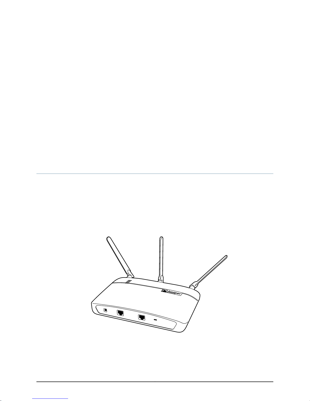
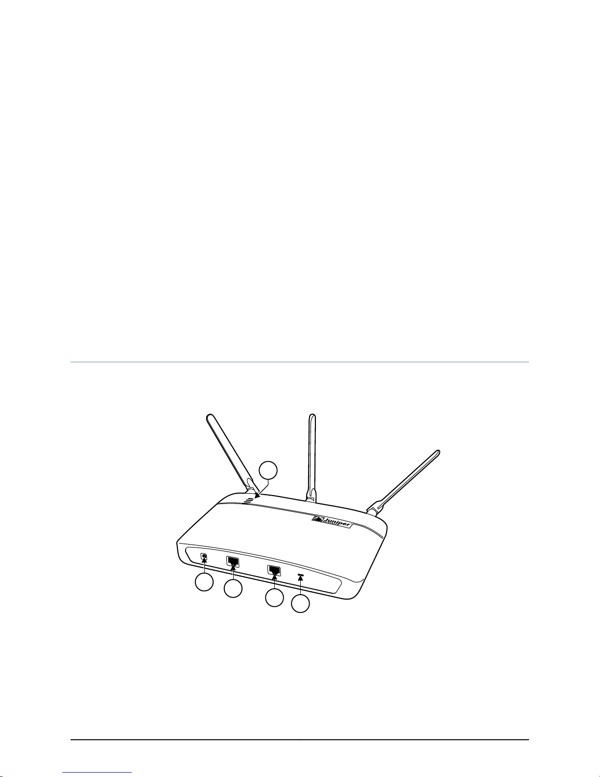
AX411 Access Point Description
The Juniper Networks AX411 Access Point provides network access for wireless clients
such as laptop or desktop computers, personal digital assistants (PDAs), and any other
device equipped with a Wi-Fi adapter. The AX411 Access Point supports the new IEEE
802.11n wireless networking standard with backward compatibility forthe IEEE 802.11a/b/g
standards.
Figure 1 on page 3 shows the AX411 Access Point.
Figure 1: AX411 Access Point
The AX411 Access Point is managed by a services gateway in the SRX200 line (SRX210,
SRX220, or SRX240)or anSRX650 Services Gateway. You manage and configure access
points through the command-line interface (CLI) and J-Web interface of the services
gateway.
3Copyright © 2012, Juniper Networks, Inc.
Page 18
AX411 Access Point Hardware Guide
You can connect and use up to two access points on the services gateway without
obtaining access point licenses. To use more than two access points, you must obtain
an additional access point license (SKU AX411-2) and install it on the services gateway.
You obtain access point licenses from your Juniper Networks representative or reseller.
Table 3 on page 4 shows the maximum number of access points supported for each
applicable services gateway type.
Table 3: Maximum Number of Access Points per Services Gateway Type
Maximum Number of AX411 Access Points SupportedServices Gateway Type
4SRX210
2SRX220
4SRX240
4SRX650
NOTE: If you have previously deployed a greater number of access points
per services gateway than specified in Table 3 on page 4, we recommend
thatwhen practicalyou reducethe number ofaccess points to those specified.
If you want to deploy more than four access points, we recommend that you
use Juniper Networks WLA Series WirelessLAN accesspoints andWLC Series
Wireless LAN Controllers.
Related
Documentation
Deploying WLANs with AX411 Access Points on page 4•
• AX411 Access Point Physical Specifications on page 6
• AX411 Access Point Front Panel and LEDs on page 9
• AX411 Access Point Rear Panel on page 10
Deploying WLANs with AX411 Access Points
To deploy a wireless network with AX411 Access Points, you install one or more access
points throughout your site and connect them to Ethernet ports on the services gateway
that manages the access points. You can provide power to the access points using Power
over Ethernet (PoE) by connecting them to services gateway ports that have PoE
capability. You can also provide power to the access points using either optional external
power supplies or PoE adapters.
You can connect the access points either directly to the SRX Series device or to a Layer
2 switch that is connected to the SRX Series device.
Figure 2 on page 5 shows a typical WLAN deployment in which four AX411 Access Points
are connected directly to an SRX210 Services Gateway.
Copyright © 2012, Juniper Networks, Inc.4
Page 19
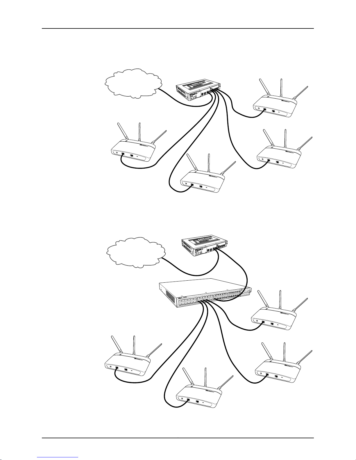
Figure 2: Typical WLAN Deployment
Inte r ne t
g033104
Inte r ne t
g033107
Chapter 1: Introduction to the AX411 Access Point
Figure 3 on page 5 shows a WLAN deployment in which four AX411 Access Points are
connected to an EX4200 Ethernet switch that is connected to an SRX210 Services
Gateway.
Figure 3: WLAN Deployment Using an Ethernet Switch
5Copyright © 2012, Juniper Networks, Inc.
Page 20

AX411 Access Point Hardware Guide
Related
Documentation
AX411 Access Point Description on page 3•
• AX411 Access Point Physical Specifications on page 6
• AX411 Access Point Front Panel and LEDs on page 9
• AX411 Access Point Rear Panel on page 10
AX411 Access Point Physical Specifications
Table 4 on page 6 lists the physical specifications of the AX411 Access Point.
Table 4: AX411 Access Point Specifications
Height
Depth
ValueSpecification
•
1.75 in. (44.4 mm) excluding antennas
•
5.9 in. (150 mm) with supplied antennas
9.5 in. (241 mm)Width
•
6.3 in. (160 mm) excluding antennas
•
7.4 in. (188 mm) with supplied antennas
2.33 lb (1.05 kg) with supplied antennasWeight
Altitude
Temperature
Maximum input power
NOTE: These specifications are
estimates and subject to change.
CAUTION: Beforeremoving or installing components of a functioning access
point, attach an electrostatic discharge (ESD) strap to an ESD point and
place the other end of the strap around your bare wrist. Failure to use an ESD
strap could result in damage to the access point.
No performance degradation up to 10,000 ft (3048
m)
Normal operation ensured in temperature range of
32°F (0°C) to 122°F (50°C)
Nonoperating storage temperature in shipping
container: –40°F (–40°C) to 158°F (70°C)
12.4 watts (1.03 ampsat 12VDC) from optionalpower
supply or 12.4 watts from PoE
42.3 BTUMaximum thermal output
70 dB(A) or less per EN ISO 7779Noise level
Copyright © 2012, Juniper Networks, Inc.6
Page 21

Chapter 1: Introduction to the AX411 Access Point
Related
Documentation
• AX411 Access Point Description on page 3
• Deploying WLANs with AX411 Access Points on page 4
• AX411 Access Point Front Panel and LEDs on page 9
• AX411 Access Point Rear Panel on page 10
7Copyright © 2012, Juniper Networks, Inc.
Page 22

AX411 Access Point Hardware Guide
Copyright © 2012, Juniper Networks, Inc.8
Page 23
CHAPTER 2
5
4
3
2
1
g033101
AX411 Access Point Components and
Features
This section includes the following topics:
•
AX411 Access Point Front Panel and LEDs on page 9
•
AX411 Access Point Rear Panel on page 10
•
AX411 Access Point Features on page 11
AX411 Access Point Front Panel and LEDs
Figure 4 on page 9 shows the front panel and LEDs of the AX411 Access Point.
Figure 4: AX411 Access Point Front Panel and LEDs
Table 5 on page 10 describes the front panel features of the access point.
9Copyright © 2012, Juniper Networks, Inc.
Page 24
AX411 Access Point Hardware Guide
Table 5: AX411 Access Point Front Panel Features
ComponentNumber
1
Power connector (use only when not providing power to the access point with
PoE
Ethernet port for connecting the access point to the SRX Series device2
Console port for diagnostics and troubleshooting3
Slot for securing the access point with a standard laptop locking cable4
LEDs; described in Table 6 on page 105
Table 6 on page 10 describes the access point LEDs.
Table 6: AX411 Access Point LEDs
On steadilyGreenStatus
DescriptionStateColorName
The access point is receiving power.On steadilyGreenPower
The access point is off.Off
The access point is starting up.On steadilyRed
The access point isbeing managed by the
SRX Series Services Gateway.
Related
Documentation
AX411 Access Point Rear Panel on page 10•
• AX411 Access Point Features on page 11
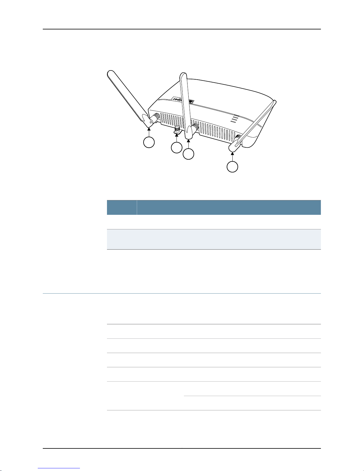
AX411 Access Point Rear Panel
Figure 5 on page 11 shows the rear panel of the AX411 Access Point.
The access point is unmanaged.Off
FlashingBlue5 GHz Radio
FlashingGreen2.4 GHz Radio
The 5 GHz radio is enabled and
broadcasting.
The 5 GHz radio is disabled.Off
The 2.4 GHz radio is enabled and
broadcasting.
The 2.4 GHz radio is disabled.Off
Copyright © 2012, Juniper Networks, Inc.10
Page 25
2
1
1
1
g033102
Chapter 2: AX411 Access Point Components and Features
Figure 5: AX411 Access Point Rear Panel
Table 7 on page 11 describes the rear panel features of the access point.
Table 7: AX411 Access Point Rear Panel Features
2
Related
Documentation
AX411 Access Point Front Panel and LEDs on page 9•
• AX411 Access Point Features on page 11
AX411 Access Point Features
The AX411 Access Point provides the features listed in Table 8 on page 11.
Table 8: AX411 Access Point Features
ComponentNumber
Antennas1
Locking screw for securing the access point to the optional mounting bracket for
wall or overhead installations
DescriptionHardware Feature
Power over Ethernet (PoE) or optional power supplyPower input
DescriptionSoftware Feature
IPv4Internet protocol
Static addressesIP address management
Dynamic Host Configuration Protocol (DHCP) client
11Copyright © 2012, Juniper Networks, Inc.
Page 26

AX411 Access Point Hardware Guide
Table 8: AX411 Access Point Features (continued)
MAC FilteringWLAN security
WEP
WPA Personal and Enterprise
WPA2 Personal and Enterprise
802.1x
AutoinstallationSystem management
J-Webbrowserinterface—for SRX Series device configuration
and management
Junos XML protocol XML application programming interface
(API)
Related
Documentation
Junos OS command-line interface (CLI)—for SRX Series
device configuration and management through the console,
Telnet, SSH, or J-Web CLI terminal
Network and Security Manager (NSM)
• AX411 Access Point Front Panel and LEDs on page 9
• AX411 Access Point Rear Panel on page 10
• AX411 Access Point Features on page 11
Copyright © 2012, Juniper Networks, Inc.12
Page 27

PART 2
Setting Up the AX411 Access Point
•
Installation Overview for the AX411 Access Point on page 15
•
Unpacking the AX411 Access Point on page 21
•
Installing the AX411 Access Point on page 23
•
Connecting the AX411 Access Point on page 31
•
Initially Configuring the AX411 Access Point Wireless LAN on page 37
13Copyright © 2012, Juniper Networks, Inc.
Page 28

AX411 Access Point Hardware Guide
Copyright © 2012, Juniper Networks, Inc.14
Page 29

CHAPTER 3
Installation Overview for the AX411 Access
Point
This section includes the following topics:
•
Site Preparation Checklist for the AX411 Access Point on page 15
•
General Site Guidelines for Installing the AX411 Access Point on page 17
•
Tools and Parts Required to Install the AX411 Access Point on page 17
•
AX411 Access Point Setup Overview on page 18
Site Preparation Checklist for the AX411 Access Point
The checklist in Table 9 on page 15 summarizes the tasks you need to perform when
preparing a site for installing the AX411 Access Point.
Table 9: Site Preparation Checklist for the AX411 Access Point Installation
Environment
Verify that
environmental factors
such as temperature
and humidity do not
exceed device
tolerances.
Power
Measure distance
between external
power sources and
device installationsite.
NotesDatePerformed ByFor More InformationItem or Task
“AX411 Access Point Physical
Specifications” on page 6
“AX411 Access Point Site
Electrical Wiring Guidelines”
on page 81
15Copyright © 2012, Juniper Networks, Inc.
Page 30

AX411 Access Point Hardware Guide
Table 9: Site Preparation Checklist for the AX411 Access Point Installation (continued)
NotesDatePerformed ByFor More InformationItem or Task
Wall Installation
Obtain the required
wall mount bracket.
Verify that the area
selected meets the
minimum
requirements.
Verify that you have
the requiredhardware
to proceed with the
installation.
Desktop Installation
Verify that the area
selected meets the
minimum
requirements.
Verify that you have
the requiredhardware
to proceed with the
installation.
Overhead Installation
Obtain the required
overhead enclosure.
“AX411 Access Point Physical
Specifications” on page 6
“Tools and Parts Required to
Install theAX411 AccessPoint”
on page 17
“AX411 Access Point Physical
Specifications” on page 6
“Tools and Parts Required to
Install theAX411 AccessPoint”
on page 17
Verify that the area
selected meets the
minimum
requirements.
Verify that you have
the required tools and
parts to proceed with
the installation.
Install the access
point mounting
bracket inside the
enclosure.
Attach the access
point to the mounting
bracket.
“AX411 Access Point Physical
Specifications” on page 6
“Tools and Parts Required to
Install theAX411 AccessPoint”
on page 17
“Installing the AX411 Access
Point Mounting Bracket in an
Overhead Enclosure” on
page 26
“Attaching the AX411 Access
Point to a Mounting Bracket in
an Overhead Enclosure” on
page 26
Copyright © 2012, Juniper Networks, Inc.16
Page 31

Chapter 3: Installation Overview for the AX411 Access Point
Table 9: Site Preparation Checklist for the AX411 Access Point Installation (continued)
NotesDatePerformed ByFor More InformationItem or Task
Install the enclosure
containing the access
point.
Cables
Acquire cables and
connectors.
Review the maximum
distance allowed for
each cable. Choose
the length of cable
based on the distance
betweenthe hardware
components being
connected.
Plan the cable routing
and management.
Related
Documentation
See the instructions provided
with the overhead enclosure.
“Interface Cable and Wire
Specifications for the AX411
Access Point” on page 101
General Site Guidelines for Installing the AX411 Access Point on page 17•
• Tools and Parts Required to Install the AX411 Access Point on page 17
• AX411 Access Point Setup Overview on page 18
General Site Guidelines for Installing the AX411 Access Point
Observe the following general guidelines when installing the AX411 Access Point:
•
To prevent overheating, the airflow around the chassis must be unrestricted. Allow
sufficient clearance between thefront andback ofthe chassisand adjacentequipment.
Ensure that there is adequate circulation in the installation location.
•
Follow the electrostatic discharge (ESD) procedures to avoid damaging equipment.
ESD can cause components to fail completely or intermittently over time.
Related
Documentation
Site Preparation Checklist for the AX411 Access Point on page 15•
• Tools and Parts Required to Install the AX411 Access Point on page 17
• AX411 Access Point Setup Overview on page 18
Tools and Parts Required to Install the AX411 Access Point
You must have the following tools and parts to install the AX411 Access Point:
17Copyright © 2012, Juniper Networks, Inc.
Page 32

AX411 Access Point Hardware Guide
•
•
•
•
•
CAT5e or CAT6 Ethernet Cable of appropriate length
Mounting bracket for wall-mounting or overhead-mounting the access point
Overhead enclosure for overhead-mounting the access point
Screws or wall anchors for wall-mounting the access point
Screwdriver or wrench appropriate for the wall-mounting screws or anchors
Related
Documentation
Site Preparation Checklist for the AX411 Access Point on page 15•
• General Site Guidelines for Installing the AX411 Access Point on page 17
• AX411 Access Point Setup Overview on page 18
AX411 Access Point Setup Overview
After you have prepared your installation site, you are ready to unpack and install the
AX411 Access Point.It is important toproceed through the installation process as described
in Table 10 on page 18.
When you install the access point as described in Table 10 on page 18, the services
gateway loads a default configuration onto the access point, which establishes basic
WLAN parameters.
After you have set up the access point and established basic WLAN connectivity, see the
Junos OS WLAN Configuration and Administration Guide and Junos OS CLI Reference for
information on performing advanced WLAN configuration.
Table 10: Installation Process Order for the AX411 Access Point
For More InformationTaskStep
Review the safety guidelines.1
“AX411 Access Point General Safety Guidelines and Warnings”
on page 63
2
3
Verify that you have prepared your site for the
installation of the access point using the checklist.
Unpack the access point and verify that all parts
are present.
Install the access point.4
“Site Preparation Checklist for the AX411 Access Point” on
page 15
“Unpacking the AX411 Access Point” on page 21
“Verifying Parts Received with the AX411 Access Point” on
page 21
“Installing the AX411 AccessPoint on a Flat Surface” on page 23
“Installing the AX411 Access Point on a Wall” on page 23
“Installing the AX411 Access Point in an Overhead Enclosure”
on page 25
Copyright © 2012, Juniper Networks, Inc.18
Page 33

Chapter 3: Installation Overview for the AX411 Access Point
Table 10: Installation Process Order for the AX411 Access Point (continued)
For More InformationTaskStep
5
Connect the access point to the SRX Series device
and to power.
Configure the wireless LAN.6
Test connectivity to the wireless LAN.7
Documentation
Related
“Installing the AX411 Access Point Antennas” on page 33
“Connecting the AX411 Access Point to the SRX Series Device”
on page 33
“Providing Power to the AX411 Access Point Using Power over
Ethernet” on page 33
“Providing Power to the AX411 Access Point Using the Power
Supply” on page 34
“AX411AccessPoint Wireless LANInitial Software Configuration
Overview” on page 37“Installing Licenses for the AX411 Access
Point on the SRX Series Device” on page 39“Configuring AX411
Access Point Country-Specific Settings” on page 42
“Testing Connectivity to the AX411 Access Point Wireless LAN”
on page 46
• Site Preparation Checklist for the AX411 Access Point on page 15
• General Site Guidelines for Installing the AX411 Access Point on page 17
• Tools and Parts Required to Install the AX411 Access Point on page 17
19Copyright © 2012, Juniper Networks, Inc.
Page 34

AX411 Access Point Hardware Guide
Copyright © 2012, Juniper Networks, Inc.20
Page 35

CHAPTER 4
Unpacking the AX411 Access Point
This section includes the following topics:
•
Unpacking the AX411 Access Point on page 21
•
Verifying Parts Received with the AX411 Access Point on page 21
Unpacking the AX411 Access Point
The AX411 Access Point is shipped in a cardboard carton.
NOTE: The device is maximally protected inside the shipping carton. Do not
unpack it until you are ready to begin installation.
To unpack the access point:
1. Open the box in which the device is shipped.
2. Verify the parts received against the lists in “Verifying Parts Received with the AX411
Access Point” on page 21.
3. Store the shipping box and packing material in case you need to return or move the
device at a later time.
Related
Documentation
Verifying Parts Received with the AX411 Access Point on page 21•
Verifying Parts Received with the AX411 Access Point
The AX411 Access Point shipping carton contains a packing list that includes all parts
and accessories available with the device. Check the parts in the shipment against the
items on the packing list. The packing list specifies the part numbers and descriptions of
each part in your order.
If any part is missing, contact your Juniper Networks customer service representative.
The shipping carton contains the chassis and parts listed in Table 11 on page 22.
21Copyright © 2012, Juniper Networks, Inc.
Page 36

AX411 Access Point Hardware Guide
Table 11: Parts List for the AX411 Access Point
QuantityComponent
1Access point
3Antennas
1Juniper Networks Product Warranty
1End User License Agreement
1AX411 Access Point Getting Started Guide
1Security Products Safety Guide
1Juniper Compliance Form Letter
1Product Registration
Related
Documentation
• Unpacking the AX411 Access Point on page 21
Copyright © 2012, Juniper Networks, Inc.22
Page 37

CHAPTER 5
Installing the AX411 Access Point
This section includes the following topics:
•
Installing the AX411 Access Point on a Flat Surface on page 23
•
Installing the AX411 Access Point on a Wall on page 23
•
Installing the AX411 Access Point in an Overhead Enclosure on page 25
•
Removing the AX411 Access Point Plastic Cover on page 28
Installing the AX411 Access Point on a Flat Surface
You can install the AX411 Access Point on a desk, on a table, or on another level surface.
The device isshipped withrubber feet attached. The rubberfeet are necessaryto stabilize
the device on the surface.
To install the device on a level surface:
1. Make sure that the rubber feet are attached to the bottom of the chassis.
2. Place the device on the surface with the Juniper Networks logo facing up.
Related
Documentation
Site Preparation Checklist for the AX411 Access Point on page 15•
Installing the AX411 Access Point on a Wall
To install the AX411 Access Point on a wall, perform the following procedures:
1.
Installing the AX411 Access Point Mounting Bracket on a Wall on page 23
2.
Attachingthe AX411AccessPoint to a MountingBracketInstalled on a Wall onpage 24
Installing the AX411 Access Point Mounting Bracket on a Wall
To install the access point mounting bracket on a wall:
1. Obtain the optional mounting bracket from your Juniper Networks reseller. The
mounting bracket is not supplied with the access point.
2. Locate the place on the wall where you intended to mount the access point.
23Copyright © 2012, Juniper Networks, Inc.
Page 38

g033106
AX411 Access Point Hardware Guide
3. Use the mounting bracket as a template to mark the locations for two screws that
4. If necessary, install anchors for the screws to distribute the weight of the access point
5. Attach the mounting bracket to the wall using screws appropriate to the wall and
Figure 6: Attaching the Mounting Bracket to a Wall
secure the mounting bracket to the wall. If practical, use screw holes on opposite
sides or edges of the mounting bracket.
into the wall.
anchoring system.
Attaching the AX411 Access Point to a Mounting Bracket Installed on a Wall
To attach the AX411 Access Point to its mounting bracket:
1. If you are installing the AX411 Access Point on a wall above a suspended ceiling, first
remove the plastic cover from the access point as described in “Removing the AX411
Access Point Plastic Cover” on page 28.
2. Locate the two pins protruding from the underside of the access point.
3. Orient the access point so that the captive screw on the rear panel matches the tab
on the mounting bracket.
4. Press the access point against the mounting bracket so that the two pins go through
the enlarged portions of the keyhole slots on the raised ears at each edge of the
mounting bracket.
5. Slide the access point so that the pins engage the narrower portions of the keyhole
slots in the mounting bracket.
6. Secure the access point to the mounting bracket by tightening the captive screw on
the rear panel of the access point.
Copyright © 2012, Juniper Networks, Inc.24
Page 39

Engage pins in slots
Tighten captive screw
(opposite side)
g033105
Chapter 5: Installing the AX411 Access Point
Figure 7: Attaching the Access Point to the Mounting Bracket
Installing the AX411 Access Point in an Overhead Enclosure
This procedure describes how to install the AX411 Access Point in a typical overhead
enclosure, in this case the Oberon Wireless model 1052-00 enclosure with 34–ZDUAL
antennas. For installation in other overhead enclosures, see the specific instructions
provided with the enclosure.
To install the access point in an overhead enclosure, perform the following procedures:
1.
Installing the AX411 Access Point Mounting Bracket in an Overhead
Enclosure on page 26
2.
Attaching the AX411 Access Point to a Mounting Bracket in an Overhead
Enclosure on page 26
3.
Connecting External Antennas to the AX411 Access Point on page 27
4.
Installing the Overhead Enclosure Containing the AX411 Access Point on page 28
25Copyright © 2012, Juniper Networks, Inc.
Page 40

g033108
AX411 Access Point Hardware Guide
Installing the AX411 Access Point Mounting Bracket in an Overhead Enclosure
Use the hardware provided with the overhead enclosure to install the mounting bracket
inside the enclosure. Attach the bracket inside the enclosure with at least two screws of
size 8-32 or M4 or larger. For specific procedures, see the instructions provided with the
enclosure.
Figure 8: Installing the Mounting Bracket in an Overhead Enclosure
Attaching the AX411 Access Point to a Mounting Bracket in an Overhead Enclosure
To attach the AX411 Access Point to a mounting bracket installed inside an overhead
enclosure:
1. Locate the two pins protruding from the underside of the access point.
2. Orient the access point so that the captive screw on the rear panel matches the tab
on the mounting bracket.
3. Press the access point against the mounting bracket so that the two pins go through
the enlarged portions of the keyhole slots on the raised ears at each edge of the
mounting bracket.
Copyright © 2012, Juniper Networks, Inc.26
Page 41

Engage pins in slots
Tighten captive screw
(opposite side)
g033105
Chapter 5: Installing the AX411 Access Point
4. Slide the access point so that the pins engage the narrower portions of the keyhole
slots in the mounting bracket.
5. Secure the access point to the mounting bracket by tightening the captive screw on
the rear panel of the access point.
Figure 9: Attaching the Access Point to the Mounting Bracket
Connecting External Antennas to the AX411 Access Point
For overhead enclosures with external antennas, use this procedure to connect the
external antennas:
1. If necessary, install the antennas in the enclosure. Refer to the instructions provided
with the antennas and the enclosure.
2. Connect one antenna cable to each antenna connector on the back of the AX411
Access Point and tighten it finger tight. The order and arrangement of the antenna
connections do not matter.
3. Arrange the antenna cables within the enclosure so that they do not interfere with
the opening or closing of the enclosure door. If necessary, use cable ties to bundle the
antenna cables neatly.
27Copyright © 2012, Juniper Networks, Inc.
Page 42

Release latches at one
edge of chassis and lift
metal chassis edge slightly
Release latches at
remaining edge and lift
metal chassis out of
plastic cover
g033119
AX411 Access Point Hardware Guide
Installing the Overhead Enclosure Containing the AX411 Access Point
See theinstructions provided with the overheadenclosure to install the enclosure at your
site.
Removing the AX411 Access Point Plastic Cover
The decorative plastic cover of the AX411 Access Point does not meet flammability
requirements for installations in environmental airspaces. The space above a suspended
ceiling may constitute an environmental airspace if it is used as a plenum for the building
ventilation system. You must remove the plastic cover whenever you install the access
point in an environmental airspace. You can remove the plastic cover without affecting
the operation or performance of the access point.
To remove the plastic cover:
1. Turn the access point over so that the underside of the device faces upward.
2. Locate the retaining latches at each corner that latch the plastic cover onto the metal
chassis. The latches are shown in Figure 10 on page 28.
Figure 10: Releasing the Plastic Cover
3. On one edge of the access point, press both tabs away from the metal chassis while
simultaneously lifting that edge of the chassis away from the plastic cover.
Copyright © 2012, Juniper Networks, Inc.28
Page 43

Chapter 5: Installing the AX411 Access Point
4. Repeat Step 3 for the remaining edge of the chassis.
5. Lift the metal chassis away from the plastic cover.
Related
Documentation
• Installing the AX411 Access Point Mounting Bracket in an Overhead Enclosure on page 26
• Attaching the AX411 Access Point to a Mounting Bracket in an Overhead Enclosure on
page 26
• Installing the Overhead Enclosure Containing the AX411 Access Point on page 28
29Copyright © 2012, Juniper Networks, Inc.
Page 44

AX411 Access Point Hardware Guide
Copyright © 2012, Juniper Networks, Inc.30
Page 45

CHAPTER 6
Connecting the AX411 Access Point
This section includes the following topics:
•
AX411 Access Point Connection Overview on page 31
•
Installing the AX411 Access Point Antennas on page 33
•
Connecting the AX411 Access Point to the SRX Series Device on page 33
•
Providing Power to the AX411 Access Point Using Power over Ethernet on page 33
•
Providing Power to the AX411 Access Point Using the Power Supply on page 34
•
Powering On and Powering Off the AX411 Access point on page 35
AX411 Access Point Connection Overview
To establish a wireless LAN using AX411 Access Points, you connect the access point to
the SRX Series device and to a power source, as shown in Figure 11 on page 32.
31Copyright © 2012, Juniper Networks, Inc.
Page 46

g033103
Omit power supply if
connecting access point
to Power over Ethernet
(PoE) port.
AX411 Access Point Hardware Guide
Figure 11: AX411 Access Point Basic Connections
Related
Documentation
Table 12 on page 32 describes the connections.
Table 12: AX411 Access Point Basic Connections
For More InformationConnection
Access point antennas
Ethernet connection to SRX
Series device
Connection to a power source
Installing the AX411 Access Point Antennas on page 33•
• Connecting the AX411 Access Point to the SRX Series Device on page 33
“Installing the AX411 Access Point Antennas” on page 33
“Connecting External Antennas to the AX411 Access Point”
on page 27
“Connecting the AX411 Access Point tothe SRX SeriesDevice”
on page 33
“ProvidingPowerto theAX411 Access Point UsingPowerover
Ethernet” on page 33
“Providing Power to the AX411 Access Point Using the Power
Supply” on page 34
“Powering On and Powering Off the AX411 Access point” on
page 35
Copyright © 2012, Juniper Networks, Inc.32
Page 47

• Providing Power to the AX411 Access Point Using Power over Ethernet on page 33
• Providing Power to the AX411 Access Point Using the Power Supply on page 34
Installing the AX411 Access Point Antennas
If youare not mounting the AX411 Access Point in an enclosure or other arrangement that
uses external antennas, install the three antennas provided with the access point. To
install the access point antennas:
1. Locate the three antennas supplied with the access point.
2. Engage each antenna with the connector on the rear panel of the access point and
tighten its thumbscrew until snug.
Chapter 6: Connecting the AX411 Access Point
Related
Documentation
AX411 Access Point Connection Overview on page 31•
• Connecting External Antennas to the AX411 Access Point on page 27
• Providing Power to the AX411 Access Point Using Power over Ethernet on page 33
• Providing Power to the AX411 Access Point Using the Power Supply on page 34
Connecting the AX411 Access Point to the SRX Series Device
To connect the AX411 Access Point to the SRX Series device:
1. Locate the port on the SRX Series device to which you are connecting the access
point. We recommend that you use a port other than ge-0/0/0 unless you are using
an advanced configuration. If you are providing power to the access point using Power
over Ethernet (PoE), make sure that the port supports PoE.
2. Connect one end of a CAT5e or CAT6 Ethernet cable to the intended port on the SRX
Series device.
3. Connect the other end of the cable to the Ethernet port on the access point.
Related
Documentation
AX411 Access Point Connection Overview on page 31•
• Installing the AX411 Access Point Antennas on page 33
• Providing Power to the AX411 Access Point Using Power over Ethernet on page 33
• Providing Power to the AX411 Access Point Using the Power Supply on page 34
Providing Power to the AX411 Access Point Using Power over Ethernet
The preferred method of supplying power to the AX411 Access Point is with Power over
Ethernet (PoE). This technology allows the transmission of electrical power to remote
devices over the same cables that the Ethernet traffic uses.
33Copyright © 2012, Juniper Networks, Inc.
Page 48

AX411 Access Point Hardware Guide
To connect the access point to a PoE power source:
1. Locate a PoE-capable port on the device to which you are connecting the access
2. If necessary, enable PoE on the interface to which you areconnecting the accesspoint.
3. Connect the access point to the PoE port using a standard CAT5e or CAT6 Ethernet
4. After connecting the access point to the PoE port, check the Power LED on the top of
point. If you are connecting the access point directly to the SRX Series Services
Gateway, ensure that the services gateway has PoE capability. See the hardware
guide for your SRX Series Services Gateway for information about PoE.
For an SRX Series Services Gateway, the Junos OS command-line interface (CLI)
command for enabling PoE on a port is:
set poe interface interface-name maximum-power 12.4
To enable PoE on all PoE-capable ports:
set poe interface all maximum-power 12.4
cable.
the access point to make sure the device is receiving power.
Related
Documentation
Powering On and Powering Off the AX411 Access point on page 35•
• AX411 Access Point Connection Overview on page 31
• Installing the AX411 Access Point Antennas on page 33
• Connecting the AX411 Access Point to the SRX Series Device on page 33
• Providing Power to the AX411 Access Point Using the Power Supply on page 34
Providing Power to the AX411 Access Point Using the Power Supply
If you do not use Power over Ethernet (PoE) to provide power to the AX411 Access Point,
you must use the power supply.
To connect the access point to the power supply:
1. Obtain the power supply from your Juniper Networks reseller. The power supply is not
provided with the access point.
2. Connect the DC power cable on the power supply to the access point.
3. Connect the AC power cord to the socket on the power supply.
4. Plug the AC power cord into an AC power outlet at your site.
5. Check the Power LED on the top of the access pointto make sure thedevice isreceiving
power.
Related
Documentation
Powering On and Powering Off the AX411 Access point on page 35•
• AX411 Access Point Connection Overview on page 31
• Installing the AX411 Access Point Antennas on page 33
Copyright © 2012, Juniper Networks, Inc.34
Page 49

• Connecting the AX411 Access Point to the SRX Series Device on page 33
• Providing Power to the AX411 Access Point Using Power over Ethernet on page 33
Powering On and Powering Off the AX411 Access point
The access point does not have a dedicated power switch. The access point is powered
on whenever either of the following two conditions is met:
•
The access point is receiving power from an Ethernet connection configured for Power
over Ethernet (PoE)
•
The access point is connected to the optional power supply
To power on the access point:
1. Do one of the following:
•
Connect the access point Ethernet port to an Ethernet connection configured for
PoE.
Chapter 6: Connecting the AX411 Access Point
Related
Documentation
•
Connect the Power connector on the front panel of the access point to the optional
power supply.
2. Check that the Power LED on the top of the access point lights steadily green.
To power off the access point:
1. Do one of the following:
•
If the access point is powered by PoE, disconnect the Ethernet cable connected to
the access point Ethernet port.
•
If the access point is powered by the optional power supply, disconnect the power
supply from the Power connector on the access point front panel.
2. Check that the Power LED on the top of the access point is unlit.
• AX411 Access Point Connection Overview on page 31
• Providing Power to the AX411 Access Point Using Power over Ethernet on page 33
• Providing Power to the AX411 Access Point Using the Power Supply on page 34
35Copyright © 2012, Juniper Networks, Inc.
Page 50

AX411 Access Point Hardware Guide
Copyright © 2012, Juniper Networks, Inc.36
Page 51

CHAPTER 7
Initially Configuring the AX411 Access Point
Wireless LAN
This section includes the following topics:
•
AX411 Access Point Wireless LAN Initial Software Configuration Overview on page 37
•
Installing Licenses for the AX411 Access Point on the SRX Series Device on page 39
•
AX411 Access Point Configuration Example: Layer 2 Mode (CLI) on page 40
•
AX411 Access Point Configuration Example: Layer 3 Mode (CLI) on page 41
•
Configuring AX411 Access Point Country-Specific Settings on page 42
•
Testing Connectivity to the AX411 Access Point Wireless LAN on page 46
•
Returning the AX411 Access Point to the Factory Default Settings on page 46
AX411 Access Point Wireless LAN Initial Software Configuration Overview
The procedures inthis topicdescribe howto establish communication between theAX411
Access Point and the SRX Series Services Gateway that manages it. When this
communication is established, the Status LED on the access point lights green, showing
that the access point is being managed by the services gateway. Then the services
gateway loads a default configuration onto the access point that establishes a basic
wireless LAN.
Once you have established communication between the access point and the services
gateway, you can perform advanced software configuration of the access point as
described in the Junos OS WLAN Configuration and Administration Guide.
If one or more access points are connected to the built-in Ethernet ports on the services
gateway other than ge-0/0/0, and the ports are in their factory default configuration,
each access point will automatically obtain an IP address using DHCP, and the services
gateway will deliver a default configuration to the access point. The Status LED on the
access point will light green, showing that the access point is being managed by the
services gateway. By default, the services gateway will accommodate up to two access
points. You can connect and use more than two access points if you also install access
point licenses on the services gateway.
For services gateways in the SRX200 line, the factory default settings establish a VLAN
consisting of all of the built-in ports except 0/0 (interface ge-0/0/0). These ports all
37Copyright © 2012, Juniper Networks, Inc.
Page 52

AX411 Access Point Hardware Guide
have a family setting of “ethernet-switching.” The VLAN has a logical interface that has
an IPaddress and belongsto theTrust zone. DHCP is enabled for the VLAN. Access points
connected to these ports operate in Layer 2 management mode by default.
For theSRX650 Services Gateway,the factory default settings establish a logical interface
for each of the four built-in Ethernet ports except ge-0/0/0. Each logical interface has
an IPaddress andbelongs to the Trust zone. DHCP is enabled on each port. Access points
connected to these ports operate in Layer 3 management mode by default.
For more information about access point Layer 2 and Layer 3 management modes, see
the Junos OS WLAN Configuration and Administration Guide.
The easiest way to check whether the services gateway is properly configured to
communicate with the access point is to perform the sequence of tasks described in
Table 13 on page 38. If at the end of this sequence the Status LED on the access point is
steady green and you can detect the juniper-default wireless network with a laptop or
other Wi-Fi device, the services gateway is properly configured.
Table 13: AX411 Access Point Wireless LAN Basic Software Configuration
For More InformationTask
Install access point licenses onthe SRXSeries
Services Gateway(onlyrequired for more than
two access points).
Check that the access point is connected to
the services gateway.
Check that the access point is powered on.
Configure country-specific settings (only
requiredfor ETSI andWorldwideregion access
points with SKUs AX411–E and AX411–W).
Test connectivity to the AX411 Access Point
wireless LAN.
“Installing Licenses for the AX411 Access Point
on the SRX Series Device” on page 39
“Connecting the AX411 Access Point to the SRX
Series Device” on page 33
“PoweringOn andPoweringOff theAX411 Access
point” on page 35
“Configuring AX411 Access Point Country-Specific
Settings” on page 42
“AX411 Access Point Country and Channel
Support” on page 85
“Testing Connectivity to the AX411 Access Point
Wireless LAN” on page 46
The most importantaspect ofthe servicesgateway configuration is that the accesspoint
must be able to obtain an IP address from the services gateway using DHCP. The access
point must obtain an IP address using DHCP in order for the services gateway to manage
the access point, even if the access point is configured to use a static IP address. The
factory default configuration for services gateways in the SRX200 line enables DHCP
for the logicalinterface of the VLAN to which all ofthe built-in portsexcept0/0 (interface
ge-0/0/0) belong. The factory default configuration for SRX650 Services Gateways
enables DHCP on the logical interface for each of the built-in ports except 0/0.
If the ports of your services gateway are not in their factory default configurations, see
“AX411 Access Point Configuration Example: Layer 2 Mode (CLI)” on page 40 and “AX411
Access Point Configuration Example: Layer 3 Mode (CLI)” on page 41 for examples of
Copyright © 2012, Juniper Networks, Inc.38
Page 53

Chapter 7: Initially Configuring the AX411 Access Point Wireless LAN
how you can configure the services gateway ports for access points in Layer 2 or Layer
3 operation.
Related
Documentation
Installing Licenses for the AX411 Access Point on the SRX Series Device on page 39•
• Connecting the AX411 Access Point to the SRX Series Device on page 33
• Configuring AX411 Access Point Country-Specific Settings on page 42
• Testing Connectivity to the AX411 Access Point Wireless LAN on page 46
• AX411 Access Point Configuration Example: Layer 2 Mode (CLI) on page 40
• AX411 Access Point Configuration Example: Layer 3 Mode (CLI) on page 41
Installing Licenses for the AX411 Access Point on the SRX Series Device
You can connect and use up to two AX411 Access Points on the services gateway without
obtaining an access point license. To connect more than two access points, you must
obtain an access point license and install it on the services gateway. You obtain access
point licenses from your Juniper Networks representative or reseller.
Licenses are available for two access points. The licenses are cumulative; for example,
if you have a services gateway that comes with support for two access points and you
install a two-access-point license (SKU AX411-2), you can configure and manage up to
four access points.
Licenses are delivered in the form of a text file containing a block of alphanumeric data,
as shown in the following example:
li29183743 4ky27y acasck 82fsj6 jzsn4q ix8i8d adj7kr
8uq38t ix8i8d jzsn4q ix8i8d 4ky27y acasck
82fsj6 ii8i7e adj7kr 8uq38t ks2923 a9382e
With the
Command-Line
Interface
The following two procedures describe how to install an access point license key using
the CLI and the J-Web interface. For more information about managing licenses, see the
Junos OS Administration Guide.
1. Open the file containing the license in a text editor and copy the text of the license
onto the clipboard.
If you have not already done so, establish a console connection with the SRX Series
2.
Services Gateway as described in the hardware guide for the services gateway, and
log into the CLI.
3. At the CLI prompt, enter:
admin@srx650–tp# request system license add terminal
4. When prompted, type or paste the license text.
5. Press Ctrl+D.
6. Commit your changes:
admin@srx650–tp# commit
commit complete
39Copyright © 2012, Juniper Networks, Inc.
Page 54

AX411 Access Point Hardware Guide
With the J-Web
Interface
Related
Documentation
1. Start the J-Web interface by browsing to the IP address of the management interface
on the services gateway.
2. Choose Maintain > Licenses to navigate to the License page.
3. In the Installed Licenses area, click Add to open the Add Licenses window.
4. In the License Key Text box, type or paste the license text.
5. Click OK.
AX411 Access Point Wireless LAN Initial Software Configuration Overview on page 37•
• Testing Connectivity to the AX411 Access Point Wireless LAN on page 46
AX411 Access Point Configuration Example: Layer 2 Mode (CLI)
The following example shows one way to use the Junos OS CLI to configure the services
gateway so that access points are in Layer 2 management mode similar to the factory
default configuration in the SRX200 line of services gateways. The example shown in
the procedure below is based on configuring Gigabit Ethernet ports on a GPIM installed
in slot 1 of an SRX650 Services Gateway, but you can adapt it for use in other situations.
For information about other configurations see the Junos OS WLAN Configuration and
Administration Guide and the Junos OS Interfaces and Routing Configuration Guide.
1. Establish a CLI session with the services gateway and log in to the device.
2. Enter configuration mode:
configure
[edit]
admin@srx650–tp#
3. Create an interface range containing the access point ports:
admin@srx650–tp# set interfaces interface-range AP-interfaces member ge-1/0/0
admin@srx650–tp# set interfaces interface-range AP-interfaces member ge-1/0/1
admin@srx650–tp# set interfaces interface-range AP-interfaces member ge-1/0/2
admin@srx650–tp# set interfaces interface-range AP-interfaces member ge-1/0/3
admin@srx650–tp# set interfaces interface-range AP-interfaces member ge-1/0/4
4. Configure the interface range for family type “ethernet-switching” and make its
interfaces members of a VLAN:
admin@srx650–tp# set interfaces interface-range AP-interfaces unit 0 family
ethernet-switching vlan members vlan-trust
5. Configure a logical interface with an IP address for the VLAN:
admin@srx650–tp# set interfaces vlan unit 0 family inet address 192.168.1.5
6. Add the VLAN logical interface to the Trust security zone:
admin@srx650–tp# set security zones security-zone trust interfaces vlan.0
7. Configure a DHCP router entry for the VLAN IP address:
admin@srx650–tp# set system services dhcp router 192.168.1.5
Copyright © 2012, Juniper Networks, Inc.40
Page 55

Chapter 7: Initially Configuring the AX411 Access Point Wireless LAN
8. Configure a DHCP pool with IP addresses for the access points and wireless clients:
admin@srx650–tp# set system services dhcp pool 192.168.1.0/24 address-range low
192.168.1.2 high 192.168.1.254
9. Configure the VLAN with an ID number and designate its Layer 3 interface as the
interface you created in Step 5:
admin@srx650–tp# set vlans vlan-trust vlan-id 3
admin@srx650–tp# set vlans vlan-trust l3-interface vlan.0
10. Configure a DHCP pool with IP addresses for the access points and wireless clients:
admin@srx650–tp# set system services dhcp pool 192.168.1.0/24 address-range low
192.168.1.2 high 192.168.1.254
11. Enable HTTP and HTTPS Web management services on the VLAN interface:
admin@srx650–tp# set system services web-management http interface vlan.0
admin@srx650–tp# set system services web-management https interface vlan.0
12. Commit your changes:
admin@srx650–tp# commit
commit complete
AX411 Access Point Configuration Example: Layer 3 Mode (CLI)
The following example shows one way to use the Junos OS CLI to configure the services
gateway so that access points are in Layer 3 management mode similar to the factory
defaultconfigurationof the built-in portson the SRX650 ServicesGateway. Theexample
shown in the procedure below is based on configuring Gigabit Ethernet ports 0 through
4 on a GPIM installed in slot 1 of an SRX650 Services Gateway, but you can adapt it for
use in other situations. For information about other configurations, see the Junos OS
WLAN Configuration and Administration Guideand the Junos OS Interfaces and Routing
Configuration Guide.
1. Establish a CLI session with the services gateway and log in to the device.
2. Enter configuration mode:
configure
[edit]
admin@srx650–tp#
3. Create logical interfaces for the ports to which the access points are connected:
admin@srx650–tp# set interfaces ge–1/0/0 unit 0 family inet address 192.168.4.1/24
admin@srx650–tp# set interfaces ge–1/0/1 unit 0 family inet address 192.168.5.1/24
admin@srx650–tp# set interfaces ge–1/0/2 unit 0 family inet address 192.168.6.1/24
admin@srx650–tp# set interfaces ge–1/0/3 unit 0 family inet address 192.168.7.1/24
admin@srx650–tp# set interfaces ge–1/0/4 unit 0 family inet address 192.168.8.1/24
4. Configure DHCP gateway addresses for each of the ports:
admin@srx650–tp# set system services dhcp pool 192.168.4.0/24 address-rangelow
admin@srx650–tp# set system services dhcp pool 192.168.5.0/24 address-range low
192.168.4.2 high 192.168.4.254
192.168.5.2 high 192.168.5.254
41Copyright © 2012, Juniper Networks, Inc.
Page 56

AX411 Access Point Hardware Guide
5. Configure DHCP address pools for each of the ports:
6. Add each logical interface to a valid security zone:
admin@srx650–tp# set system services dhcp pool 192.168.6.0/24address-rangelow
192.168.6.2 high 192.168.6.254
admin@srx650–tp# set system services dhcp pool 192.168.7.0/24 address-range low
192.168.7.2 high 192.168.7.254
admin@srx650–tp# set system services dhcp pool 192.168.8.0/24address-rangelow
192.168.8.2 high 192.168.8.254
admin@srx650–tp# set system services dhcp pool 192.168.4.0/24 router 192.168.4.1
admin@srx650–tp# set system services dhcp pool 192.168.5.0/24 router 192.168.5.1
admin@srx650–tp# set system services dhcp pool 192.168.6.0/24 router 192.168.6.1
admin@srx650–tp# set system services dhcp pool 192.168.7.0/24 router 192.168.7.1
admin@srx650–tp# set system services dhcp pool 192.168.8.0/24 router 192.168.8.1
admin@srx650–tp# set security zones security-zone trust interfaces ge–1/0/0.0
admin@srx650–tp# set security zones security-zone trust interfaces ge–1/0/1.0
admin@srx650–tp# set security zones security-zone trust interfaces ge–1/0/2.0
admin@srx650–tp# set security zones security-zone trust interfaces ge–1/0/3.0
admin@srx650–tp# set security zones security-zone trust interfaces ge–1/0/4.0
7. Commit your changes:
admin@srx650–tp# commit
commit complete
Configuring AX411 Access Point Country-Specific Settings
Under most circumstances, you do not need to set any country-specific settings in order
to install, configure, and use the access point. However, the following two access point
versions are supplied with the country code set to a null value:
•
ETSI (SKU AX411-E)
•
Worldwide (SKU AX411-W)
For these units, you must set the country code and two other country-specific settings
before you can use the access point.
To configure the country code and the two other country-specific settings, perform one
of the following procedures before testing connectivity to the access point:
Copyright © 2012, Juniper Networks, Inc.42
Page 57

Chapter 7: Initially Configuring the AX411 Access Point Wireless LAN
With the
Command-Line
Interface
1. Find your country in the country and channel support table in “AX411 Access Point
Country and Channel Support” on page 85 and write down the following:
• The two-letter country code in the first column
• Whether the word“None” appears in eitherof theRadio 1or Radio 2 columns(fourth
and fifth columns)under the“Channels Supported” header, and,if so, whichcolumn
in which it appears
• Whether 40 MHz channel bandwidth is supported for the 2.4 GHz frequency band
(Radio 2), shown in the seventh column
• Whether 40 MHz channel bandwidth is supported for the 5 GHz frequency band
(Radio 1), shown in the eighth column
2. If you have not already done so, establish a console connection with the SRX Series
Services Gateway as described in the hardware guide for the services gateway, and
log into the CLI.
3. Enter configuration mode:
admin@> edit
Entering configuration mode
4. Create an access point instance in the SRX Series device configuration:
admin@# set wlan access-point name mac-address mac_address
where name is the name you want to apply to the access point and mac_address is
the MAC address written on the serial number label on the bottom of the access point.
For example:
admin@# set wlan access-point silver mac-address 0012cfc75dc0
5. Set the country code for the access point instance:
admin@# set wlan access-point name access-point-options country country_code
where country_code is the two-letter country code for your location, entered in
uppercase letters.
For example:
admin@# set wlan access-point silver access-point-options country GB
6. If either 2.4 GHz or 5 GHz operation is not allowed in your country, as indicated by the
word “None” in either the fourth or fifth column of the table, use the following CLI
command to disable either the 2.4 GHz radio (Radio 2) or the 5 GHz radio (Radio 1)
as appropriate:
admin@# set wlan access-point name radio 1|2 radio-options radio-off
7. If 40 MHz channel bandwidth is not supported for the 2.4 GHz frequency band in your
country, as indicated by an “N” in the seventh column of the table, use the following
CLI command to set the 2.4 GHz channel bandwidth to 20 MHz. The default channel
bandwidth is 40 MHz, so if the column contains “Y” you can skip to the next step:
admin@# set wlan access-point name radio 2 radio-options channel bandwidth 20
43Copyright © 2012, Juniper Networks, Inc.
Page 58

AX411 Access Point Hardware Guide
8. If 40 MHz channel bandwidth is not supported for the 5 GHz frequency band in your
9. Commit your changes:
country, as indicated by an “N” in the eighth column of the table, use the following CLI
command to set the 5 GHz channel bandwidth to 20 MHz. The default channel
bandwidth is 40 MHz, so if the column contains “Y” you can skip to the next step:
admin@# set wlan access-point name radio 1 radio-options channel bandwidth 20
admin@#> commit
commit complete
With the J-Web
Interface
1. Find your country in the country and channel support table in “AX411 Access Point
Country and Channel Support” on page 85 and write down the following:
• Whether the word“None” appears in eitherof theRadio 1or Radio 2 columns(fourth
and fifth columns)under the“Channels Supported” header, and,if so, whichcolumn
it appears in
• Whether 40 MHz channel bandwidth is supported for the 2.4 GHz frequency band
(Radio 2), shown in the seventh column
• Whether 40 MHz channel bandwidth is supported for the 5 GHz frequency band
(Radio 1), shown in the eighth column
2. If you have not alreadydone so, start the J-Web interface bybrowsingto theIP address
or hostname of the SRX Series device.
3. In J-Web, choose Configure > Wireless LAN > Settings to open the Wlan Settings pane.
4. On the Wlan Settings pane, click the Add button above the access point list.
5. On the Add - Access Point dialog box:
a. In the Access point name box, type a name for the access point.
b. In the MAC address box, enter the MAC address printed on the serial number label
on the bottom of the access point.
c. In the Country menu, choose the country in which the access point is operating.
6. At the bottom of the Add - Access Point dialog box, click OK.
7. On the lower part of the Wlan Settings pane, click the Add button above the radio list.
The Add - Radio dialog box opens with the Radio tab at the front.
Copyright © 2012, Juniper Networks, Inc.44
Page 59

Chapter 7: Initially Configuring the AX411 Access Point Wireless LAN
8. On the Add - Radio dialog box Radio tab:
a. From the Radio Type menu, choose Radio 1 (the 5 GHz radio).
b. If 5 GHz operation is not allowed in your country, as indicated by the word “None”
in the fifth column of the table, mark the Disabled radio button below the Radio
Type menu.
c. Click the Radio Settings tab to bring it to the front.
d. If 40 MHz channel bandwidth is not supported for the 5 GHz frequency band in
your country, as indicated by an “N” in the eighth column of the table, click the
Channel Bandwidth menu and choose 20 to set the 5 GHz channel bandwidth to
20 MHz. The default channel bandwidth is 40 MHz, so if the column contains “Y”
you can skip this step.
9. At the bottom of the Add - Radio dialog box, click OK.
10. On the lower part of the Wlan Settings pane, click the Add button above the radio list.
The Add - Radio dialog box opens with the Radio tab at the front.
Related
Documentation
11. On the Add - Radio dialog box Radio tab:
a. From the Radio Type menu, choose Radio 2 (the 2.4 GHz radio).
b. If 2.4 GHz operation is not allowed in your country, as indicated by the word “None”
in the fourth column of the table, mark the Disabled radio button below the Radio
Type menu.
c. Click the Radio Settings tab to bring it to the front.
d. If 40 MHz channel bandwidth is not supported for the 2.4 GHz frequency band in
your country, as indicated by an “N” in the seventh column of the table, click the
Channel Bandwidth menu and choose 20 to set the 2.4 GHz channel bandwidth
to 20 MHz. The default channel bandwidth is 40 MHz, so if the column contains
“Y” you can skip this step.
12. At the bottom of the Add - Radio dialog box, click OK.
13. At the top of the J-Web window, choose Commit Options > Commit.
AX411 Access Point Country and Channel Support on page 85•
• AX411 Access Point Wireless LAN Initial Software Configuration Overview on page 37
• Testing Connectivity to the AX411 Access Point Wireless LAN on page 46
45Copyright © 2012, Juniper Networks, Inc.
Page 60

AX411 Access Point Hardware Guide
Testing Connectivity to the AX411 Access Point Wireless LAN
After you have installed and connected the AX411 Access Point and configured the SRX
Series device with basic settings, test whether the wireless LAN is functioning.
1. Confirm that the access point is connected to the services gateway. We recommend
that you connect the access point to an Ethernet port other than ge-0/0/0.
2. Confirm that the Power LED on the access point is lit steady green, showing that the
access point is powered on.
3. Confirm that the Status LED on the access point is lit steady green, showing that the
access point is being managed by the services gateway.
4. Use a laptop computer or other wireless device to view the available networks near
where the access point is installed. You should find a security-enabled network with
juniper-default as its SSID. The default wireless LAN settings are described in Table
14 on page 46.
5. Connect to the juniper-default network. When prompted for a WPA2-PSK security
key, enter juniper-wireless.
Table 14: AX411 Access Point Default Configuration Settings
ValueParameter
juniper-defaultSSID
EnabledSSID broadcast
WPA2–PSKSecurity
juniper-wirelessWPA2–PSK Security Key
AESEncapsulation
Related
Documentation
AX411 Access Point Wireless LAN Initial Software Configuration Overview on page 37•
• Powering On and Powering Off the AX411 Access point on page 35
• Installing Licenses for the AX411 Access Point on the SRX Series Device on page 39
Returning the AX411 Access Point to the Factory Default Settings
Normally, the AX411 Access Point returns itself to factory default settings every time it
restarts. The access point then obtains an IP address from the services gateway that
manages it and waits for the services gateway to deliver its configuration settings. If the
access point does not receive its IP address and configuration from the services gateway
and the Status LED does not light steadily green, you might find it necessary to manually
return the access point to the factory default settings.
Copyright © 2012, Juniper Networks, Inc.46
Page 61

Chapter 7: Initially Configuring the AX411 Access Point Wireless LAN
To return the AX411 Access Point to factory default settings:
1. Connect the access point’s console connector to your computer’s serial port using an
Ethernet cable and the DB9-to-RJ45 adapter used to configure SRX Series Services
Gateways.
2. Establish a console session with the access point using a program such as
HyperTerminal and the following settings:
•
Bits per second: 115200
•
Data bits: 8
•
Parity: None
•
Stop bits: 1
•
Flow control: None
3. Restart the access point:
•
If the access point is powered by Power over Ethernet (PoE), disconnect and then
reconnect the Ethernet cable at the Ethernet port on the access point.
•
If the access point is powered by the optional power supply, disconnect and then
reconnect the power supply at the power connector on the access point.
The access point startup messages scroll up the HyperTerminal window.
4. Watch for the AP Startup main menu to appear in the HyperTerminal window:
AP Startup -- Main Menu
1 - Start AP Application
2 - Display Utility Menu
Select (1, 2):
5. Within five seconds, enter 2 to open the Utility menu. If the access point does not
detect a response within five seconds, it continues its start sequence. If you miss the
five-second window, go back to step 3 of this procedure.
The AP Startup menu opens:
AP Startup -- Utility Menu
1 - Reset to factory default configuration
2 - Continue to boot
6. At the AP Startup menu prompt, enter 1.
7. The access point resets itself to its factory default settings and continues its starting
sequence.
47Copyright © 2012, Juniper Networks, Inc.
Page 62

AX411 Access Point Hardware Guide
Copyright © 2012, Juniper Networks, Inc.48
Page 63

PART 3
Hardware Maintenance, Replacement,
and Troubleshooting Procedures for the
AX411 Access Point
•
Monitoring the AX411 Access Point on page 51
•
Maintaining the AX411 Access Point on page 55
•
Troubleshooting the AX411 Access Point on page 57
49Copyright © 2012, Juniper Networks, Inc.
Page 64

AX411 Access Point Hardware Guide
Copyright © 2012, Juniper Networks, Inc.50
Page 65

CHAPTER 8
Monitoring the AX411 Access Point
This section includes the following topics:
•
Monitoring the AX411 Access Point with the LEDs on page 51
•
Monitoring the AX411 Access Point with the Command-Line Interface on page 52
Monitoring the AX411 Access Point with the LEDs
At regular intervals, check the AX411 Access Point LEDs to make sure that the access
point is functional and has not encountered an error condition.
Under normal operating circumstances, the access point LEDs will be in the condition
shown in Table 15 on page 51.
Table 15: Access Point LED Normal Indications
DescriptionStateColorLED
On steadilyGreenPower
On steadilyGreenStatus
FlashingBlueRadio 1 (5
GHz radio)
FlashingGreenRadio2 (2.4
GHz radio)
The access point is powered on and operating
normally.
The access point is being managed by the SRX
Series Services Gateway.
The 5 GHz radio is enabled and broadcasting.
This LED will be off if the 5 GHz radio is disabled,
for example, if the radio settings for the country
code do not allow the use of 5 GHz channels.
The 2.4 GHz radio is enabled and broadcasting.
This LED will be off if the 2.4GHz radio isdisabled,
for example, if the radio settings for the country
code do not allow the use of 2.4 GHz channels.
Table 16 on page 52 describes the LED indications that occur while the access point is
starting up.
51Copyright © 2012, Juniper Networks, Inc.
Page 66

AX411 Access Point Hardware Guide
Table 16: Access Point LED Starting Indications
StateRadio2Radio1StatusPower
The access point has just started up.BlueBlueOffRed
The access point is loading Uboot.BlueBlueOffOff
The access has finished loading Uboot.BlueBlueOffGreen
The access point has started and is
requesting an IP address with DHCP, but is
not yet being managed by SRX Series device
and has not received its configuration from
the SRX Series device.
The access point has received an IP address
is being managed by the SRX Series device
and has received its configuration from the
SRX Series device.
Related
Documentation
OffOffOffGreen
OffOffGreenGreen
Troubleshooting the AX411 Access Point with the LEDs on page 57•
• Monitoring the AX411 Access Point with the Command-Line Interface on page 52
Monitoring the AX411 Access Point with the Command-Line Interface
To monitor the AX411 Access Point with the command-line interface (CLI):
•
Use the show wlan access-points command to display a list of access points and basic
settings, as shown in the following example:
root@srx210–1> show wlan access-points
Active access points information
Access-Point Type Interface Radio-mode/Channel
gold Ext vlan an/36, bgn/6
silver Ext vlan an/56, bgn/11
•
To view detailed information about an access point, use the show wlan access-points
detail access-point-name command to display detailed information, as shown in the
following example:
root@srx210–1> show wlan access-points detail gold
Active access point detail information
Access Point : gold
Type : External
Location : Default Location
Serial Number : 850001761
Firmware Version : 10.1.2.3
Access Interface : vlan
Packet Capture : Disabled
Copyright © 2012, Juniper Networks, Inc.52
Page 67

Ethernet Port:
MAC Address : 00:12:CF:C7:5D:00
IPv4 Address : 20.0.0.73
Radio1:
Status : On
MAC Address : 00:12:CF:C7:5D:00
Mode : IEEE 802.11a/n
Channel : 36 (5180 MHz)
Radio2:
Status : On
MAC Address : 00:12:CF:C7:5D:10
Mode : IEEE 802.11b/g/n
Channel : 6 (2437 MHz)
Chapter 8: Monitoring the AX411 Access Point
Related
Documentation
• Monitoring the AX411 Access Point with the LEDs on page 51
53Copyright © 2012, Juniper Networks, Inc.
Page 68

AX411 Access Point Hardware Guide
Copyright © 2012, Juniper Networks, Inc.54
Page 69

CHAPTER 9
Maintaining the AX411 Access Point
This section includes the following topic:
•
Routine Maintenance Procedures for the AX411 Access Point on page 55
Routine Maintenance Procedures for the AX411 Access Point
Purpose For optimum access point performance, perform preventive maintenance procedures
regularly.
Action • Inspect the installation site for moisture, loose wires or cables, and excessive dust.
• Make sure that the power cable is arranged so it does not obstruct access to other
device components.
• Make sure that airflow is unobstructed around the device and into the air intake vents.
• Check the Status LEDs on the top of the device.
Related
Documentation
• Monitoring the AX411 Access Point with the LEDs on page 51
• Monitoring the AX411 Access Point with the Command-Line Interface on page 52
55Copyright © 2012, Juniper Networks, Inc.
Page 70

AX411 Access Point Hardware Guide
Copyright © 2012, Juniper Networks, Inc.56
Page 71

CHAPTER 10
Troubleshooting the AX411 Access Point
This section includes the following topics:
•
Troubleshooting the AX411 Access Point with the LEDs on page 57
•
Troubleshooting Communication Issues Between the AX411 Access Point and the
Services Gateway on page 58
Troubleshooting the AX411 Access Point with the LEDs
Table 17 on page 57 describes the most common problems indicated by the LEDs and
suggests the most common solutions.
Table 17: Typical Access Point LED Problem Indications
SolutionProbable CauseLED Indication
•
Power LED not
lit
•
Power LED is
red
•
All four LEDs
flash
simultaneously
Status LED not lit
The access point is not
receiving power or is
receiving inadequate power
The access point is not
being managed by the
services gateway.
If using the optional power supply, confirm that all cables are connected
correctly and that the power cord is plugged into a functioning outlet.
If using Power over Ethernet (PoE):
•
Confirm that the device and port to which the access point is connected
has PoE capability.
•
Confirm that the port is properly configured for PoE. The port should be
configured to allocate 12.4 watts of power for the access point.
•
Confirm that the access point is connected with a CAT5e or CAT6
Ethernet cable shorter than 328 feet (100 meters) in length.
•
Confirm that the Ethernet cable is connected properly. Try disconnecting
and then reconnecting the Ethernet cable.
See “Powering On and Powering Off the AX411 Access point” on page 35
for more information.
Confirm that the access point Ethernet port is connected to an Ethernet
port on the services gateway, and that the Link LED is lit on the services
gateway Ethernet port.
Confirm that DHCP is enabled for the services gateway ports to which the
access points are connected. DHCP is enabled by default. For examples of
services gateway configurations that enable DHCP for services gateway
ports, see “AX411 AccessPoint Configuration Example: Layer 2 Mode (CLI)”
on page 40 and “AX411 Access Point Configuration Example: Layer 3 Mode
(CLI)” on page 41.
57Copyright © 2012, Juniper Networks, Inc.
Page 72

AX411 Access Point Hardware Guide
Table 17: Typical Access Point LED Problem Indications (continued)
SolutionProbable CauseLED Indication
5 GHz or 2.4 GHz
radio LEDs not
flashing
Documentation
The access point radios are
not broadcasting or are not
enabled.
Related
Troubleshooting Communication Issues Between the AX411 Access Point and the
•
Services Gateway on page 58
• Monitoring the AX411 Access Point with the LEDs on page 51
• Monitoring the AX411 Access Point with the Command-Line Interface on page 52
Confirm that the country-specific settings are set properly on the access
point. The radios are enabled or disabled according to the country code
setting. For information about country-specific settings, see “Configuring
AX411 Access Point Country-Specific Settings” on page 42.
If more than two access points are connected to the services gateway,
confirm that you have installed the appropriate access point licenses on
the services gateway. Both access point radios will be disabled unless the
services gateway has licenses for the access points. For more information,
see “InstallingLicenses for theAX411 AccessPoint onthe SRXSeries Device”
on page 39.
Troubleshooting Communication Issues Between the AX411 Access Point and the
Services Gateway
Problem The access point Power LED lights steadily green to show that the device has started
properly, but the Status LED does not light green to show that the device is managed by
the SRX Series Services Gateway. This LED indication shows that the access point is not
communicating with the services gateway and is not receiving its configuration from the
services gateway.
Solution When the access point is not communicating with the services gateway, the issue is
Related
Documentation
usually with the DHCP configuration of the SRX Series device. Ensure that the services
gateway interface to which the access point is connected belongs to a security zone that
is configured to allow DHCP traffic.
If your network uses an external device as the DHCP server instead of the DHCP server
capability of the SRX Series device, you must configure the DHCP server so that the SRX
Series device is the access point’s default gateway for DHCP.
For examples of services gateway configurations that enable DHCP for services gateway
ports, see “AX411 Access Point Configuration Example: Layer 2 Mode (CLI)” on page 40
and “AX411 Access Point Configuration Example: Layer 3 Mode (CLI)” on page 41
• Troubleshooting the AX411 Access Point with the LEDs on page 57
Copyright © 2012, Juniper Networks, Inc.58
Page 73

PART 4
Appendixes
•
Safety and Regulatory Compliance Information on page 61
•
AX411 Access Point Power Guidelines, Requirements, and Specifications on page 81
•
AX411 Access Point Wireless LAN Channels and Frequencies on page 85
•
AX411 Access Point Interface Cable Specifications and Connector Pinouts on page 101
•
AX411 Access Point Antenna Specifications on page 105
•
Contacting Customer Support and Returning the AX411 Access Point
Hardware on page 111
59Copyright © 2012, Juniper Networks, Inc.
Page 74

AX411 Access Point Hardware Guide
Copyright © 2012, Juniper Networks, Inc.60
Page 75

APPENDIX A
Safety and Regulatory Compliance
Information
This section includes the following topics:
•
AX411 Access Point Definitions of Safety Warning Levels on page 61
•
AX411 Access Point General Safety Guidelines and Warnings on page 63
•
AX411 Access Point Fire Suppression Procedures and Equipment on page 67
•
AX411 Access Point Installation Instructions Warnings on page 68
•
AX411 Access Point Maintenance and Operational Safety Guidelines and
Warnings on page 69
•
AX411 Access Point Electrical Safety Guidelines and Warnings on page 74
•
AX411 Access Point WiFi Interoperability on page 75
•
AX411 Access Point Agency Approvals on page 76
•
AX411 Access Point Compliance Statements for EMC Requirements on page 77
•
AX411 Access Point Compliance Statements for Environmental
Requirements on page 78
•
AX411 Access Point Compliance Statements for Acoustic Noise on page 79
AX411 Access Point Definitions of Safety Warning Levels
This guide uses the following three levels of safety warnings:
NOTE: You might find this information helpful in a particular situation or
might otherwise overlook it.
CAUTION: You need to observe the specified guidelines to avoid minor injury
or discomfort to you or severe damage to the access point.
61Copyright © 2012, Juniper Networks, Inc.
Page 76

AX411 Access Point Hardware Guide
WARNING: This symbol means danger. Youare ina situation thatcould cause
bodily injury. Before you work on any equipment, be aware of the hazards
involved with electrical circuitry and be familiar with standard practices for
preventing accidents.
Waarschuwing Dit waarschuwingssymbool betekent gevaar. U verkeert in
een situatie die lichamelijk letsel kan veroorzaken. Voordat u aan enige
apparatuur gaat werken, dient u zich bewust te zijn van de bij elektrische
schakelingenbetrokken risico's en dient u op de hoogte te zijn van standaard
maatregelen om ongelukken te voorkomen.
Varoitus Tämä varoitusmerkki merkitsee vaaraa. Olet tilanteessa, joka voi
johtaa ruumiinvammaan. Ennen kuintyöskenteletminkään laitteiston parissa,
ota selvää sähkökytkentöihin liittyvistä vaaroista ja tavanomaisista
onnettomuuksien ehkäisykeinoista.
Attention Ce symbole d'avertissement indique un danger.Vous vous trouvez
dans une situation pouvantcauser des blessures ou des dommages corporels.
Avant de travailler sur un équipement, soyez conscient des dangers posés
par les circuits électriques et familiarisez-vous avec les procédures
couramment utilisées pour éviter les accidents.
Warnung Dieses Warnsymbol bedeutet Gefahr. Sie befinden sich in einer
Situation, die zu einer Körperverletzung führen könnte. Bevor Sie mit der
Arbeit an irgendeinem Gerät beginnen, seien Sie sich der mit elektrischen
Stromkreisen verbundenen Gefahren und der Standardpraktiken zur
Vermeidung von Unfällen bewußt.
Avvertenza Questo simbolo di avvertenza indica un pericolo. La situazione
potrebbe causare infortuni alle persone. Prima di lavorare su qualsiasi
apparecchiatura, occorre conoscere i pericoli relativi ai circuiti elettrici ed
essere al corrente delle pratiche standard per la prevenzione di incidenti.
Advarsel Dette varselsymboletbetyr fare. Du befinner deg i en situasjon som
kan føre til personskade. Før du utfører arbeid på utstyr, må du vare
oppmerksom på de faremomentene som elektriske kretser innebærer, samt
gjøre deg kjent med vanlig praksis når det gjelder å unngå ulykker.
Aviso Este símbolo de aviso indica perigo. Encontra-se numa situação que
lhe poderá causar danos físicos. Antes de começara trabalhar com qualquer
equipamento, familiarize-se com os perigos relacionados com circuitos
eléctricos, e com quaisquer práticas comuns que possam prevenir possíveis
acidentes.
¡Atención! Este símbolo de aviso significa peligro. Existe riesgo para su
integridad física. Antes de manipular cualquier equipo, considerar los riesgos
que entraña la corriente eléctrica y familiarizarse con los procedimientos
estándar de prevención de accidentes.
Copyright © 2012, Juniper Networks, Inc.62
Page 77

Appendix A: Safety and Regulatory Compliance Information
Varning!Denna varningssymbol signalerarfara. Du befinner dig i en situation
som kan leda till personskada. Innan du utför arbete på någon utrustning
måste du vara medveten om farorna med elkretsar och känna till vanligt
förfarande för att förebygga skador.
Related
Documentation
AX411 Access Point General Safety Guidelines and Warnings on page 63•
• AX411 Access Point Fire Suppression Procedures and Equipment on page 67
• AX411 Access Point Installation Instructions Warnings on page 68
• AX411 Access Point Maintenance and Operational Safety Guidelines and Warnings on
page 69
• AX411 Access Point Electrical Safety Guidelines and Warnings on page 74
• AX411 Access Point WiFi Interoperability on page 75
AX411 Access Point General Safety Guidelines and Warnings
•
General Safety Guidelines and Warnings on page 63
•
Qualified Personnel Warning on page 64
•
Restricted Access Area Warning on page 64
•
Preventing Electrostatic Discharge Damage to the Access Point on page 66
General Safety Guidelines and Warnings
The following guidelines help ensure your safety and protect the access point from
damage. The list of guidelines might not address all potentially hazardous situations in
your working environment, so be alert and exercise good judgment at all times.
•
Perform only the procedures explicitly described in this guide. Make sure that only
authorized service personnel perform other system services.
•
Keep the area around the chassis clear and free from dust before, during, and after
installation.
•
Keep tools away from areas where people could trip on them.
•
Wear safety glasses if you are working under any conditions that could be hazardous
to your eyes.
•
Do not perform any actions that create a potential hazard to people or make the
equipment unsafe.
•
Never install or manipulate wiring during electrical storms.
•
Never install electrical jacks in wet locations unless the jacks are specifically designed
for wet environments.
•
Do not open or remove chassis covers or sheet metal parts unless instructions are
provided in this guide. Such an action could cause severe electrical shock.
63Copyright © 2012, Juniper Networks, Inc.
Page 78

AX411 Access Point Hardware Guide
•
Do not push or force any objects through any opening in the chassis frame. Such an
action could result in electrical shock or fire.
•
Avoid spilling liquid onto the access point chassisor ontoany access point component.
Such an action could cause electrical shock or damage the access point.
•
Avoid touching uninsulated electrical wires or terminals that have not been
disconnected from their power source. Such an action could cause electrical shock.
Qualified Personnel Warning
WARNING: Only trained and qualified personnel should install or replace the
access point.
Waarschuwing Installatie en reparaties mogen uitsluitend door getraind en
bevoegd personeel uitgevoerd worden.
Varoitus Ainoastaan koulutettuja pätevähenkilökuntasaa asentaatai vaihtaa
tämän laitteen.
Attention Tout installation ou remplacement de l'appareil doit être réalisé
par du personnel qualifié et compétent.
WarnungGerät nur von geschultem,qualifiziertem Personal installieren oder
auswechseln lassen.
Avvertenza Solo personale addestrato e qualificato deve essere autorizzato
ad installare o sostituire questo apparecchio.
Advarsel Kun kvalifisert personell med riktig opplæring bør montere eller
bytte ut dette utstyret.
Aviso Este equipamento deverá ser instalado ou substituído apenas por
pessoal devidamente treinado e qualificado.
¡Atención! Estos equipos deben ser instalados y reemplazados
exclusivamentepor personal técnico adecuadamentepreparadoy capacitado.
Varning! Denna utrustning ska endast installeras och bytas ut av utbildad
och kvalificerad personal.
Restricted Access Area Warning
WARNING: The access point is intended for installation in restricted access
areas. A restricted access area is an area to which access can be gained only
by service personnel through the use of a special tool, lock and key, or other
means of security, and which is controlled by the authority responsible for
the location.
Copyright © 2012, Juniper Networks, Inc.64
Page 79

Appendix A: Safety and Regulatory Compliance Information
Waarschuwing Dit toestel is bedoeld voor installatieop plaatsenmet beperkte
toegang.Een plaatsmet beperktetoegang iseen plaats waar toegangslechts
door servicepersoneel verkregen kan worden door middel van een speciaal
instrument, een slot en sleutel, of een ander veiligheidsmiddel, en welke
beheerd wordt door de overheidsinstantie die verantwoordelijk is voor de
locatie.
Varoitus Tämä laite on tarkoitettu asennettavaksi paikkaan, johon pääsy on
rajoitettua. Paikka, johon pääsyon rajoitettua, tarkoittaa paikkaa, johon vain
huoltohenkilöstö pääsee jonkin erikoistyökalun, lukkoon sopivan avaimen
tai jonkin muun turvalaitteen avulla ja joka on paikasta vastuussa olevien
toimivaltaisten henkilöiden valvoma.
Attention Cet appareil est à installer dans des zones d'accès réservé. Ces
dernièressont des zones auxquelles seulle personnel de service peut accéder
en utilisant un outil spécial, un mécanisme de verrouillage et une clé, ou tout
autre moyen de sécurité. L'accès aux zones de sécurité est sous le contrôle
de l'autorité responsable de l'emplacement.
Warnung Diese Einheit ist zur Installation in Bereichen mit beschränktem
Zutritt vorgesehen. Ein Bereich mit beschränktem Zutritt ist ein Bereich, zu
dem nur Wartungspersonal mit einem Spezialwerkzeugs, Schloß und
Schlüssel oder anderer Sicherheitsvorkehrungen Zugang hat, und der von
dem für die Anlage zuständigen Gremium kontrolliert wird.
AvvertenzaQuestaunità deve essere installatain un'area ad accessolimitato.
Un'area ad accesso limitato è un'area accessibile solo a personale di
assistenza tramite un'attrezzo speciale, lucchetto, o altri dispositivi di
sicurezza, ed è controllata dall'autorità responsabile della zona.
Advarsel Denne enheten er laget for installasjon i områder med begrenset
adgang.Et område med begrenset adgang gir kun adgang til servicepersonale
som bruker et spesielt verktøy, lås og nøkkel, eller en annen
sikkerhetsanordning, og det kontrolleresav den autoriteten som er ansvarlig
for området.
Aviso Esta unidade foiconcebida parainstalaçãoem áreas de acesso restrito.
Uma área de acesso restrito é uma área à qual apenas tem acesso o pessoal
de serviço autorizado, que possua uma ferramenta, chave e fechadura
especial, ou qualquer outra forma de segurança. Esta área é controlada pela
autoridade responsável pelo local.
¡Atención! Esta unidad ha sido diseñada para instalarse en áreas de acceso
restringido. Área de acceso restringido significa un área a la que solamente
tiene acceso el personal de servicio mediante la utilización de una herramienta
especial, cerradura con llave, o algún otro medio de seguridad, y que está
bajo el control de la autoridad responsable del local.
Varning! Denna enhet är avsedd för installation i områden med begränsat
tillträde. Ett område med begränsat tillträde får endast tillträdas av
65Copyright © 2012, Juniper Networks, Inc.
Page 80

AX411 Access Point Hardware Guide
servicepersonal med ett speciellt verktyg, lås och nyckel, eller annan
säkerhetsanordning, och kontrolleras av den auktoritet som ansvarar för
området.
Preventing Electrostatic Discharge Damage to the Access Point
Many access point hardware componentsare sensitive to damage from static electricity.
Some components can be impaired by voltages as low as 30 V. You can easily generate
potentially damaging static voltages whenever you handle plastic or foam packing
material or if you move components across plastic or carpets. Observe the following
guidelines to minimize the potential for electrostatic discharge (ESD) damage, which
can cause intermittent or complete component failures:
•
Always use an ESD wrist strap or ankle strap, and verify that it is in direct contact with
your skin.
CAUTION: For safety, periodically check the resistance value of the ESD
strap. The measurement should be in the range of 1 to 10 Mohms.
•
When handling any component that is removed from the chassis, verify that the
equipment end of your ESD strap is attached to one of the ESD points on the chassis.
•
Avoid contact between the component and your clothing. ESD voltages emitted from
clothing can still damage components.
•
When removing or installing a component, always place it component-side up on an
antistatic surface, inan antistaticcard rack, or in an electrostatic bag. Ifyou arereturning
a component, place it into an electrostatic bag before packing it.
Figure 12: Placing a Component into an Electrostatic Bag
Copyright © 2012, Juniper Networks, Inc.66
Page 81

Appendix A: Safety and Regulatory Compliance Information
Related
Documentation
AX411 Access Point Definitions of Safety Warning Levels on page 61•
• AX411 Access Point Fire Suppression Procedures and Equipment on page 67
• AX411 Access Point Installation Instructions Warnings on page 68
• AX411 Access Point Maintenance and Operational Safety Guidelines and Warnings on
page 69
• AX411 Access Point Electrical Safety Guidelines and Warnings on page 74
• AX411 Access Point WiFi Interoperability on page 75
AX411 Access Point Fire Suppression Procedures and Equipment
In the event of a fire emergency involving devices and other network equipment, the
safety of people is the primary concern. Establish procedures for protecting people in
the event of a fire emergency, provide safety training, and properly provision fire-control
equipment and fire extinguishers.
In addition, establish procedures to protect your equipment in the event of a fire
emergency. Juniper Networks products should be installed in an environment suitable
for electronic equipment. We recommend that fire suppression equipment be available
in the event of a fire in the vicinity of the equipment and that all local fire, safety, and
electrical codes and ordinances be observed when installing and operating your
equipment.
In theevent ofan electrical hazard or an electrical fire, first turnpower offto theequipment
at the source. Then use a Type C fire extinguisher to extinguish the fire. Type C fire
extinguishers, which use noncorrosive fire retardants such as carbon dioxide (CO2) and
Halotron™, are most effective for suppressing electrical fires. Type C fire extinguishers
displace the oxygen from the point of combustion to eliminate the fire. For extinguishing
fire on or around equipment that draws air from the environment for cooling, use this
type of inert oxygen displacement extinguisher instead of an extinguisher that leave
residues on equipment.
Do not use multipurpose Type ABC chemical fire extinguishers (dry chemical fire
extinguishers) near Juniper Networks equipment. The primary ingredient in these fire
extinguishers is monoammonium phosphate, which is very sticky and difficult to clean.
In addition, in minute amounts of moisture, monoammonium phosphate can become
highly corrosive and corrodes most metals.
Any equipment in a room in which a chemical fire extinguisher has been discharged is
subject to premature failure and unreliable operation. The equipment is considered to
be irreparably damaged.
NOTE: To keep warranties effective,do notuse a dry chemical fire extinguisher
to control a fire at or near a Juniper Networks access point. If a dry chemical
fire extinguisher is used, the unit is no longer eligible for coverage under a
service agreement.
67Copyright © 2012, Juniper Networks, Inc.
Page 82

AX411 Access Point Hardware Guide
We recommend that you dispose of any irreparably damaged equipment in an
environmentally responsible manner.
Related
Documentation
AX411 Access Point Definitions of Safety Warning Levels on page 61•
• AX411 Access Point General Safety Guidelines and Warnings on page 63
• AX411 Access Point Installation Instructions Warnings on page 68
• AX411 Access Point Maintenance and Operational Safety Guidelines and Warnings on
page 69
• AX411 Access Point Electrical Safety Guidelines and Warnings on page 74
• AX411 Access Point WiFi Interoperability on page 75
AX411 Access Point Installation Instructions Warnings
WARNING: Read the installation instructions before you connect the access
point to a power source.
Waarschuwing Raadpleeg de installatie-aanwijzingenvoordatu het systeem
met de voeding verbindt.
Varoitus Lue asennusohjeetennen järjestelmänyhdistämistä virtalähteeseen.
AttentionAvantde brancher le systèmesur lasource d'alimentation,consulter
les directives d'installation.
Related
Documentation
Warnung Lesen Sie die Installationsanweisungen, bevor Sie das System an
die Stromquelle anschließen.
AvvertenzaConsultareleistruzioni di installazioneprima di collegare il sistema
all'alimentatore.
Advarsel Les installasjonsinstruksjonenefør systemetkobles til strømkilden.
Aviso Leia as instruções de instalação antes de ligar o sistema à sua fonte
de energia.
¡Atención! Ver las instrucciones de instalación antes de conectar el sistema
a la red de alimentación.
Varning! Läs installationsanvisningarna innan du kopplar systemet till dess
strömförsörjningsenhet.
AX411 Access Point Definitions of Safety Warning Levels on page 61•
• AX411 Access Point General Safety Guidelines and Warnings on page 63
• AX411 Access Point Fire Suppression Procedures and Equipment on page 67
Copyright © 2012, Juniper Networks, Inc.68
Page 83

Appendix A: Safety and Regulatory Compliance Information
• AX411 Access Point Maintenance and Operational Safety Guidelines and Warnings on
page 69
• AX411 Access Point Electrical Safety Guidelines and Warnings on page 74
• AX411 Access Point WiFi Interoperability on page 75
AX411 Access Point Maintenance and Operational Safety Guidelines and Warnings
•
Battery Handling Warning on page 69
•
Jewelry Removal Warning on page 70
•
Lightning Activity Warning on page 71
•
Operating Temperature Warning on page 72
•
Product Disposal Warning on page 73
Battery Handling Warning
WARNING: Replacing the battery incorrectly might result in an explosion.
Replace the battery only with the same or equivalent type recommended by
the manufacturer. Dispose of used batteriesaccordingto the manufacturer's
instructions.
Waarschuwing Er is ontploffingsgevaar als de batterij verkeerd vervangen
wordt. Vervang de batterij slechts met hetzelfde of een equivalent type dat
door de fabrikantaanbevolen is. Gebruiktebatterijen dienen overeenkomstig
fabrieksvoorschriften weggeworpen te worden.
Varoitus Räjähdyksen vaara, jos akku on vaihdettu väärään akkuun. Käytä
vaihtamiseen ainoastaan saman- tai vastaavantyyppistä akkua, joka on
valmistajansuosittelema. Hävitä käytetytakut valmistajanohjeiden mukaan.
Attention Danger d'explosion si la pile n'est pas remplacée correctement.
Ne la remplacer que par une pile de type semblable ou équivalent,
recommandée par le fabricant. Jeter les piles usagées conformément aux
instructions du fabricant.
Warnung Bei Einsetzen einer falschen Batterie besteht Explosionsgefahr.
Ersetzen Sie die Batterie nur durch den gleichen oder vom Hersteller
empfohlenen Batterietyp. Entsorgen Sie die benutzten Batterien nach den
Anweisungen des Herstellers.
Avvertenza Pericolo di esplosione se la batteria non è installata
correttamente. Sostituire solocon una ditipo ugualeo equivalente,consigliata
dal produttore. Eliminare le batterieusatesecondo leistruzioni del produttore.
Advarsel Det kan være fare for eksplosjon hvis batteriet skiftes på feil måte.
Skift kun med samme eller tilsvarendetype som er anbefalt av produsenten.
Kasser brukte batterier i henhold til produsentens instruksjoner.
69Copyright © 2012, Juniper Networks, Inc.
Page 84

AX411 Access Point Hardware Guide
Jewelry Removal Warning
Aviso Existe perigo de explosão se a bateria for substituída incorrectamente.
Substitua a bateria por uma bateria igual ou de um tipo equivalente
recomendado pelo fabricante. Destrua as baterias usadas conforme as
instruções do fabricante.
¡Atención! Existe peligro de explosión si la batería se reemplaza de manera
incorrecta. Reemplazar la batería exclusivamente con el mismo tipo o el
equivalente recomendado por el fabricante. Desechar las baterías gastadas
según las instrucciones del fabricante.
Varning!Explosionsfaravid felaktigtbatteribyte.Ersätt endast batteriet med
samma batterityp som rekommenderas av tillverkaren eller motsvarande.
Följ tillverkarens anvisningar vid kassering av använda batterier.
WARNING: Before working on equipment that is connected to power lines,
remove jewelry, including rings, necklaces, and watches. Metal objects heat
up when connected to power and ground and can cause serious burns or
weld the metal object to the terminals.
Waarschuwing Alvorens aan apparatuur te werken die met elektrische
leidingen is verbonden, sieraden (inclusief ringen, kettingen en horloges)
verwijderen. Metalen voorwerpen worden warm wanneer ze met stroom en
aarde zijn verbonden, en kunnen ernstige brandwonden veroorzaken of het
metalen voorwerp aan de aansluitklemmen lassen.
Varoitus Ennen kuin työskentelet voimavirtajohtoihin kytkettyjen laitteiden
parissa, ota pois kaikki korut (sormukset,kaulakorut ja kellot mukaan lukien).
Metalliesineet kuumenevat, kun ne ovat yhteydessä sähkövirran ja maan
kanssa, ja ne voivataiheuttaa vakaviapalovammojatai hitsatametalliesineet
kiinni liitäntänapoihin.
AttentionAvantd'accéderà cetéquipement connectéaux lignesélectriques,
ôtertout bijou (anneaux, colliers et montres compris).Lorsqu'ils sont branchés
à l'alimentation et reliés à la terre, les objets métalliques chauffent, ce qui
peut provoquerdes blessuresgravesou souder l'objet métallique aux bornes.
Warnung Vor der Arbeit an Geräten, die an das Netz angeschlossen sind,
jeglichen Schmuck (einschließlich Ringe, Ketten und Uhren) abnehmen.
Metallgegenstände erhitzen sich, wenn sie an das Netz und die Erde
angeschlossen werden, und können schwere Verbrennungen verursachen
oder an die Anschlußklemmen angeschweißt werden.
Avvertenza Prima di intervenire su apparecchiature collegate alle linee di
alimentazione, togliersi qualsiasi monile (inclusi anelli, collane, braccialetti
ed orologi). Gli oggetti metallici si riscaldano quando sono collegatitra punti
Copyright © 2012, Juniper Networks, Inc.70
Page 85

Appendix A: Safety and Regulatory Compliance Information
di alimentazione e massa: possono causare ustioni gravi oppure il metallo
può saldarsi ai terminali.
Advarsel Fjern alle smykker (inkludert ringer, halskjeder og klokker) før du
skal arbeide på utstyr som er koblet til kraftledninger. Metallgjenstandersom
er koblet til kraftledninger og jord blir svært varme og kan forårsake alvorlige
brannskader eller smelte fast til polene.
Aviso Antes de trabalhar em equipamento que esteja ligado a linhas de
corrente, retire todas as jóias que estiver a usar (incluindo anéis, fios e
relógios). Os objectos metálicos aquecerão em contacto com a corrente e
em contacto com a ligação à terra, podendo causar queimaduras graves ou
ficarem soldados aos terminais.
¡Atención! Antes de operar sobre equipos conectados a líneas de
alimentación, quitarse las joyas (incluidos anillos, collares y relojes). Los
objetosde metalse calientancuando se conectan a la alimentacióny a tierra,
lo que puede ocasionar quemaduras graves o que los objetos metálicos
queden soldados a los bornes.
Lightning Activity Warning
Varning! Tag av alla smycken (inklusive ringar, halsband och armbandsur)
innan duarbetar på utrustning som är koppladtill kraftledningar. Metallobjekt
hettas upp när de kopplas ihop med ström och jord och kan förorsaka
allvarliga brännskador; metallobjekt kan också sammansvetsas med
kontakterna.
WARNING: Do notwork on the system orconnect or disconnect cablesduring
periods of lightning activity.
Waarschuwing Tijdens onweer dat gepaard gaat met bliksem, dient u niet
aan het systeem te werken of kabels aan te sluiten of te ontkoppelen.
Varoitus Älä työskentele järjestelmän parissa äläkä yhdistä tai irrota
kaapeleita ukkosilmalla.
Attention Ne pas travailler sur le système ni brancher ou débrancher les
câbles pendant un orage.
Warnung Arbeiten Sie nicht am System und schließen Sie keine Kabel an
bzw. trennen Sie keine ab, wenn es gewittert.
Avvertenza Non lavorare sul sistema o collegare oppure scollegare i cavi
durante un temporale con fulmini.
AdvarselUtfør aldri arbeid på systemet,eller koble kablertil eller frasystemet
når det tordner eller lyner.
71Copyright © 2012, Juniper Networks, Inc.
Page 86

AX411 Access Point Hardware Guide
Aviso Não trabalhe no sistema ou ligue e desligue cabos durante períodos
de mau tempo (trovoada).
¡Atención! No operar el sistema ni conectaro desconectarcables durante el
transcurso de descargas eléctricas en la atmósfera.
Varning! Vid åska skall du aldrig utföra arbete på systemet eller ansluta eller
koppla loss kablar.
Operating Temperature Warning
WARNING: To prevent the access point from overheating, do not operate it
in an area that exceeds the maximum recommended ambient temperature
of 122°F (50°C). To prevent airflow restriction, allow at least 6 in. (15.2 cm)
of clearance around the ventilation openings.
Waarschuwing Om te voorkomen dat welke access point van de Juniper
Networksaccesspoint dan ook oververhitraakt,dient u deze niet te bedienen
op een plaats waar de maximale aanbevolen omgevingstemperatuur van
50°C wordt overschreden. Om te voorkomen dat de luchtstroom wordt
beperkt, dient er minstens 15,2 cm speling rond de ventilatie-openingen te
zijn.
Varoitus Ettei Juniper Networks access point-sarjan reititin ylikuumentuisi,
sitä ei saa käyttää tilassa, jonka lämpötila ylittää korkeimman suositellun
ympäristölämpötilan 50°C. Ettei ilmanvaihto estyisi, tuuletusaukkojen
ympärille on jätettävä ainakin 15,2 cm tilaa.
Attention Pour éviter toute surchauffe des routeurs de la gamme Juniper
Networks access point, ne l'utilisez pas dans une zone où la température
ambiante est supérieure à 50°C. Pour permettre un flot d'air constant,
dégagezun espaced'au moins 15,2 cm autour des ouvertures de ventilations.
WarnungUm einen access point der accesspoint vorÜberhitzung zu schützen,
darf dieser nicht in einer Gegend betrieben werden, in der die
Umgebungstemperatur das empfohlene Maximum von 50°C überschreitet.
Um Lüftungsverschlußzu verhindern, achten Sie darauf,daß mindestens 15,2
cm lichter Raum um die Lüftungsöffnungen herum frei bleibt.
Avvertenza Per evitare il surriscaldamentodei accesspoint, non adoperateli
in un locale che ecceda la temperatura ambientale massima di 50°C. Per
evitareche la circolazionedell'aria sia impedita, lasciateuno spazio di almeno
15.2 cm di fronte alle aperture delle ventole.
AdvarselUnngå overoppheting aveventuellerutere i Juniper Networks access
point Disse skal ikke brukes på steder der den anbefalte maksimale
omgivelsestemperaturenoverstiger50°C (122°F). Sørgfor atklaringen rundt
Copyright © 2012, Juniper Networks, Inc.72
Page 87

Appendix A: Safety and Regulatory Compliance Information
lufteåpningene er minst 15,2 cm (6 tommer) for å forhindre nedsatt
luftsirkulasjon.
Aviso Para evitar o sobreaquecimento do encaminhador Juniper Networks
access point, não utilize este equipamento numa área que exceda a
temperatura máxima recomendada de 50°C. Para evitar a restrição à
circulaçãode ar,deixepelo menos um espaço de 15,2 cm à voltadas aberturas
de ventilação.
¡Atención! Para impedir que un encaminador de la serie Juniper Networks
accesspoint se recaliente, no lo hagafuncionar en un área en la que se supere
la temperatura ambiente máxima recomendada de 50°C. Para impedir la
restricciónde la entradade aire, deje un espacio mínimo de 15,2 cm alrededor
de las aperturas para ventilación.
Varning! Förhindra att en Juniper Networks access point överhettas genom
att inte använda den i ett område där den maximalt rekommenderade
omgivningstemperaturen på 50°C överskrids.Förhindra att luftcirkulationen
inskränksgenom attse till attdet finns fritt utrymme på minst 15,2 cm omkring
ventilationsöppningarna.
Product Disposal Warning
WARNING: Disposal of this product must be handled according to all national
laws and regulations.
Waarschuwing Dit produkt dient volgens alle landelijke wetten en
voorschriften te worden afgedankt.
Varoitus Tämän tuotteen lopullisesta hävittämisestä tulee huolehtia kaikkia
valtakunnallisia lakeja ja säännöksiä noudattaen.
Attention La mise au rebut définitive de ce produit doit être effectuée
conformément à toutes les lois et réglementations en vigueur.
Warnung Dieses Produkt muß den geltenden Gesetzen und Vorschriften
entsprechend entsorgt werden.
Avvertenza L'eliminazione finale di questo prodotto deve essere eseguita
osservando le normative italiane vigenti in materia
AdvarselEndelig disponering av detteproduktet må skje i henholdtil nasjonale
lover og forskrifter.
Aviso A descartagem final deste produto deverá ser efectuada de acordo
com os regulamentos e a legislação nacional.
¡Atención! El desecho final de este producto debe realizarse según todas las
leyes y regulaciones nacionales
73Copyright © 2012, Juniper Networks, Inc.
Page 88

AX411 Access Point Hardware Guide
Varning!Slutligkassering avdenna produktbör skötasi enlighetmed landets
alla lagar och föreskrifter.
Related
Documentation
AX411 Access Point Definitions of Safety Warning Levels on page 61•
• AX411 Access Point General Safety Guidelines and Warnings on page 63
• AX411 Access Point Fire Suppression Procedures and Equipment on page 67
• AX411 Access Point Installation Instructions Warnings on page 68
• AX411 Access Point Electrical Safety Guidelines and Warnings on page 74
• AX411 Access Point WiFi Interoperability on page 75
AX411 Access Point Electrical Safety Guidelines and Warnings
•
In Case of Electrical Accident on page 74
•
General Electrical Safety Guidelines and Warnings on page 74
In Case of Electrical Accident
If an electrical accident results in an injury, take the following actions in this order:
1. Use caution. Be aware of potentially hazardous conditions that could cause further
injury.
2. Disconnect power from the access point.
3. If possible, send another person to get medical aid. Otherwise, assess the condition
of the victim, then call for help.
General Electrical Safety Guidelines and Warnings
•
Install the accesspoint incompliance with thefollowing local, national, or international
electrical codes:
•
United States—National Fire Protection Association (NFPA 70), United States
National Electrical Code
•
Canada—Canadian Electrical Code, Part 1, CSA C22.1
•
Other countries—International Electromechanical Commission (IEC) 60364, Part 1
through Part 7
•
Evaluated to the TN power system
•
Locate the emergency power-off switch for the room in which you are working so that
if an electrical accident occurs, you can quickly turn off the power.
•
Do notwork alone ifpotentially hazardous conditionsexist anywhere inyour workspace.
•
Never assume thatpower isdisconnectedfrom a circuit. Always check the circuit before
starting to work.
Copyright © 2012, Juniper Networks, Inc.74
Page 89

Appendix A: Safety and Regulatory Compliance Information
•
Carefully look for possible hazards in your work area, such as moist floors, ungrounded
power extension cords, and missing safety grounds.
•
Operate the access point within marked electrical ratings and product usage
instructions.
•
For the access point and peripheral equipment to function safely and correctly, use
the cables and connectors specified for the attached peripheral equipment, and make
certain they are in good condition.
Related
Documentation
AX411 Access Point Definitions of Safety Warning Levels on page 61•
• AX411 Access Point General Safety Guidelines and Warnings on page 63
• AX411 Access Point Fire Suppression Procedures and Equipment on page 67
• AX411 Access Point Installation Instructions Warnings on page 68
• AX411 Access Point Maintenance and Operational Safety Guidelines and Warnings on
page 69
• AX411 Access Point WiFi Interoperability on page 75
AX411 Access Point WiFi Interoperability
The AX411 Access Point holds the WiFi Alliance interoperability certifications described
in this section.
Wi-Fi interoperability certification ID number: WFA7729
IEEE standards:
•
IEEE 802.11a
•
IEEE 802.11b
•
IEEE 802.11g
•
IEEE 802.11n draft 2.0
•
IEEE 802.11d
•
IEEE 802.11h
Security:
•
WPA - Enterprise, Personal
•
WPA2 - Enterprise, Personal
EAP types:
•
EAP-TLS
•
EAP-TTLS/MSCHAPv2
•
PEAPv0/EAP-MSCHAPv2
75Copyright © 2012, Juniper Networks, Inc.
Page 90

AX411 Access Point Hardware Guide
•
•
Multimedia:
•
PEAPv1/EAP-GTC
EAP-SIM
WMM
Related
Documentation
AX411 Access Point Agency Approvals on page 76•
• AX411 Access Point Compliance Statements for EMC Requirements on page 77
• AX411 Access Point Compliance Statements for Environmental Requirements on
page 78
• AX411 Access Point Compliance Statements for Acoustic Noise on page 79
AX411 Access Point Agency Approvals
The access point complies with the following standards:
•
Safety:
•
CSA 60950-1 (2003) Safety of Information Technology Equipment
•
UL 60950-1 (2003) Safety of Information Technology Equipment
•
EN 60950-1 (2001) Safety of Information Technology Equipment
•
IEC 60950-1 (2001) Safety of Information Technology Equipment (with country
deviations)
•
EMC:
•
EN 300 386 V1.3.3 (2005) Telecom Network Equipment - EMC requirements
•
EMI:
•
FCC Part 15 Class B (2007) USA Radiated Emissions
•
EN 55022 Class B (2006) European Radiated Emissions
•
VCCI Class B (2007) Japanese Radiated Emissions
Copyright © 2012, Juniper Networks, Inc.76
Page 91

Appendix A: Safety and Regulatory Compliance Information
•
Immunity:
•
EN 55024 +A1+A2 (1998) Information Technology Equipment Immunity
Characteristics
•
EN-61000-3-2 (2006) Power Line Harmonics
•
EN-61000-3-3 +A1 +A2 +A3 (1995) Power Line Voltage Fluctuations
•
EN-61000-4-2 +A1 +A2 (1995) Electrostatic Discharge
•
EN-61000-4-3 +A1+A2 (2002) Radiated Immunity
•
EN-61000-4-4 (2004) Electrical Fast Transients
•
EN-61000-4-5 (2006) Surge
•
EN-61000-4-6 (2007) Immunity to Conducted Disturbances
•
EN-61000-4-11 (2004) Voltage Dips and Sags
Related
Documentation
AX411 Access Point WiFi Interoperability on page 75•
• AX411 Access Point Compliance Statements for EMC Requirements on page 77
• AX411 Access Point Compliance Statements for Environmental Requirements on
page 78
• AX411 Access Point Compliance Statements for Acoustic Noise on page 79
AX411 Access Point Compliance Statements for EMC Requirements
Canada
This Class B digital apparatus complies with Canadian ICES-003.
Cet appareil numérique de la classe B est conforme à la norme NMB-003 du Canada.
European Community
This is a Class B product.
Japan
The preceding translates as follows:
This is a Class B product based on the standard of the Voluntary Control Council for
Interference by Information Technology Equipment (VCCI). If this product is used near
77Copyright © 2012, Juniper Networks, Inc.
Page 92

AX411 Access Point Hardware Guide
a radio or television receiver in a domestic environment, it may cause radio interference.
Install and use the equipment according to the instruction manual.
United States
This equipment has been tested and found to comply with the limits for a Class B digital
device, pursuant to Part 15 of the FCC Rules. These limits are designed to provide
reasonable protection against harmful interference in a residential installation. This
equipment generates, uses and can radiate radio frequency energy and, if not installed
and used in accordance with the instructions, may cause harmful interference to radio
communications. However, there is no guarantee that interference will not occur in a
particular installation. If this equipment does cause harmful interference to radio or
television reception, which can be determined by turning the equipment off and on, the
user is encouraged to try to correct the interference by one or more of the following
measures:
•
•
Reorient or relocate the receiving antenna.
Increase the separation between the equipment and receiver.
•
Connect the equipment into an outlet on a circuit different from that to which the
receiver is connected.
•
Consult the dealer or an experienced radio/TV technician for help.
Related
Documentation
AX411 Access Point Agency Approvals on page 76•
• AX411 Access Point Compliance Statements for Environmental Requirements on
page 78
• AX411 Access Point Compliance Statements for Acoustic Noise on page 79
AX411 Access Point Compliance Statements for Environmental Requirements
This topic includes the compliance statement for the following environmental
requirement:
Lithium Battery
Batteries in this product are not based on mercury, lead, or cadmium substances. The
batteriesused inthis productare incompliance with EU Directives 91/157/EEC, 93/86/EEC,
and 98/101/EEC. The product documentation includes instructional information about
the proper method of reclamation and recycling.
Related
Documentation
AX411 Access Point Agency Approvals on page 76•
• AX411 Access Point Compliance Statements for EMC Requirements on page 77
• AX411 Access Point Compliance Statements for Acoustic Noise on page 79
Copyright © 2012, Juniper Networks, Inc.78
Page 93

Appendix A: Safety and Regulatory Compliance Information
AX411 Access Point Compliance Statements for Acoustic Noise
Maschinenlärminformations-Verordnung - 3. GPSGV, der höchste Schalldruckpegel
beträgt 70 dB(A) oder weniger gemäss EN ISO 7779.
Translation:
The maximum emitted sound pressure level is 70 dB(A) or less per EN ISO 7779.
Related
Documentation
• AX411 Access Point Agency Approvals on page 76
• AX411 Access Point Compliance Statements for EMC Requirements on page 77
• AX411 Access Point Compliance Statements for Environmental Requirements on
page 78
79Copyright © 2012, Juniper Networks, Inc.
Page 94

AX411 Access Point Hardware Guide
Copyright © 2012, Juniper Networks, Inc.80
Page 95

APPENDIX B
AX411 Access Point Power Guidelines,
Requirements, and Specifications
This section includes the following topics:
•
AX411 Access Point Site Electrical Wiring Guidelines on page 81
•
AX411 Access Point Power Supply Specifications and Requirements on page 82
AX411 Access Point Site Electrical Wiring Guidelines
Table 18 on page 81 describes the factors you must consider while planning the electrical
wiring for the AX411 Access Point at your site.
CAUTION: It is particularly important to provide a properly grounded and
shielded environment and to use electrical surge-suppression devices.
Table 18: Site Electrical Wiring Guidelines for the AX411 Access Point
GuidelineSite Wiring Factor
Signaling limitations
To ensure that signaling functions optimally:
•
Install wires correctly.
Improperly installed wires can emit radio interference.
•
Do not exceed the recommended distances or pass wires
between buildings.
The potential for damagefrom lightning strikesincreases if wires
exceed recommended distances or if wires pass between
buildings.
•
Shield all conductors.
The electromagnetic pulse (EMP) caused by lightning can
damage unshielded conductors and destroy electronic devices.
81Copyright © 2012, Juniper Networks, Inc.
Page 96

AX411 Access Point Hardware Guide
Table 18: Site Electrical Wiring Guidelines for the AX411 Access
Point (continued)
GuidelineSite Wiring Factor
Radio frequency
interference (RFI)
Electromagnetic
Compatibility (EMC)
CAUTION: To comply with intrabuilding lightning/surge requirements, the
intrabuilding wiring must be shielded. The shielding for the wiring must be
grounded at both ends.
To reduce or eliminate the emission of RFI from your site wiring:
•
Use twisted-pair cable with a good distribution of grounding
conductors.
•
Use ahigh-quality twisted-pair cable with one ground conductor
for each data signal when applicable, if you must exceed the
recommended distances.
Provide a properly grounded and shielded environment and use
electrical surge-suppression devices.
Strong sources of electromagnetic interference (EMI) can cause
the following damage:
•
Destroy the signal drivers and receivers in the device
•
Conduct power surges over the lines into the equipment,
resulting in an electrical hazard
NOTE: If yoursite issusceptible to problems withEMC, particularly
from lightning or radio transmitters, you may want to seek expert
advice.
Related
AX411 Access Point Power Supply Specifications and Requirements on page 82•
Documentation
AX411 Access Point Power Supply Specifications and Requirements
The AC power system electrical specifications for the AX411 Access Point are listed in
Table 19 on page 82.
Table 19: Power Supply Electrical Specifications for the AX411 Access
Point
SpecificationPower Requirement
100 to 240 VACAC input voltage
50 to 60 HzAC input line frequency
0.65 A maxAC system current rating
Copyright © 2012, Juniper Networks, Inc.82
Page 97

Appendix B: AX411 Access Point Power Guidelines, Requirements, and Specifications
WARNING: The AC power cord for the access point is intended for use with
the device only and not for any other use.
Related
Documentation
• AX411 Access Point Site Electrical Wiring Guidelines on page 81
83Copyright © 2012, Juniper Networks, Inc.
Page 98

AX411 Access Point Hardware Guide
Copyright © 2012, Juniper Networks, Inc.84
Page 99

APPENDIX C
AX411 Access Point Wireless LAN
Channels and Frequencies
This section includes the following topics:
•
AX411 Access Point Country and Channel Support on page 85
•
AX411 Access Point Channels and Frequency Support on page 97
AX411 Access Point Country and Channel Support
Table 20 on page 85 shows the 2.4 GHz and 5 GHz channels supported for each country
code. It also shows whether 802.11n and 40MHz channel width are supported.
Table 20: Country Codes and Wireless LAN Channels
Channels Supported
40 MHz
Supported
Country
Code
AE
AG
AN
AS
United Arab
Emirates
Antigua and
Barbuda
Netherlands
Antilles
ArgentinaAR
American
Samoa
Band
Plan/SKUCountry
World
AX411-W
World
AX411-W
World
AX411-W
World
AX411-W
AX411-W
Radio 2
(2.4 GHz)
12 13
1 2 3 4 5 6 7 8 9 10 11
12 13
1 2 3 4 5 6 7 8 9 10 11
12 13
1 2 3 4 5 6 7 8 9 10 11
12 13
1 2 3 4 5 6 7 8 9 10 11World
Radio 1
(5 GHz)
100 104 108 112 116 120 124
128 132 136 140
100 104 108 112 116 120 124
128 132 136 140
165
100 104 108 112 116 120 124
128 132 136 140 149 153 157
161 165
802.11n
Support
Radio
2
(2.4
GHz)
Radio
1
(5
GHz)
NYYNone1 2 3 4 5 6 7 8 9 10 11
NNN36 40 44 48 52 56 60 64
NNN36 40 44 48 52 56 60 64
YYY52 56 60 64 149 153 157 161
NNN36 40 44 48 52 56 60 64
85Copyright © 2012, Juniper Networks, Inc.
Page 100

AX411 Access Point Hardware Guide
Table 20: Country Codes and Wireless LAN Channels (continued)
Channels Supported
40 MHz
Supported
Country
Code
Radio
2
Band
Plan/SKUCountry
AustriaAT
AustraliaAU
ArubaAW
AzerbaijanAZ
BosniaBA
BarbadosBB
ETSI
AX411-E
World
AX411-W
World
AX411-W
World
AX411-W
World
AX411-W
World
AX411-W
Radio 2
(2.4 GHz)
1 2 3 4 5 6 7 8 9 10 11
12 13
1 2 3 4 5 6 7 8 9 10 11
12 13
1 2 3 4 5 6 7 8 9 10 11
12 13
1 2 3 4 5 6 7 8 9 10 11
12 13
1 2 3 4 5 6 7 8 9 10 11
12 13
1 2 3 4 5 6 7 8 9 10 11
12 13
Radio 1
(5 GHz)
100 104 108 112 116 132 136
140
149 153 157 161 165
100 104 108 112 116 120 124
128 132 136 140
100 104 108 112 116 120 124
128 132 136 140 149 153 157
161 165
100 104 108 112 116 120 124
128 132 136 140
149 153 157 161 165
802.11n
Support
(2.4
GHz)
Radio
1
(5
GHz)
YYY36 40 44 48 52 56 60 64
YYY36 40 44 48 52 56 60 64
NNN36 40 44 48 52 56 60 64
NNN36 40 44 48 52 56 60 64
NNN36 40 44 48 52 56 60 64
NNN36 40 44 48 52 56 60 64
BangladeshBD
BelgiumBE
BulgariaBG
BahrainBH
BermudaBM
BruneiBN
World
AX411-W
ETSI
AX411-E
ETSI
AX411-E
World
AX411-W
World
AX411-W
World
AX411-W
12 13
1 2 3 4 5 6 7 8 9 10 11
12 13
1 2 3 4 5 6 7 8 9 10 11
12 13
1 2 3 4 5 6 7 8 9 10 11
12 13
1 2 3 4 5 6 7 8 9 10 11
12 13
12 13
100 104 108 112 116 132 136
140
100 104 108 112 116 132 136
140
149 153 157 161 165
100 104 108 112 116 120 124
128 132 136 140
Copyright © 2012, Juniper Networks, Inc.86
YYY149 153 157 161 1651 2 3 4 5 6 7 8 9 10 11
YYY36 40 44 48 52 56 60 64
YYY36 40 44 48 52 56 60 64
NNN36 40 44 48 52 56 60 64
NNN36 40 44 48 52 56 60 64
NNNNone1 2 3 4 5 6 7 8 9 10 11
 Loading...