

Page 1

IN FOCUS
Published
2020-10-16
®
Junos
OS Release 20.2
Page 2

Juniper Networks, Inc.
1133 Innovation Way
Sunnyvale, California 94089
USA
408-745-2000
www.juniper.net
Juniper Networks, the Juniper Networks logo, Juniper, and Junos are registered trademarks of Juniper Networks, Inc. in
the United States and other countries. All other trademarks, service marks, registered marks, or registered service marks
are the property of their respective owners.
Juniper Networks assumes no responsibility for any inaccuracies in this document. Juniper Networks reserves the right
to change, modify, transfer, or otherwise revise this publication without notice.
IN FOCUS Junos®OS Release 20.2
Copyright © 2020 Juniper Networks, Inc. All rights reserved.
The information in this document is current as of the date on the title page.
ii
YEAR 2000 NOTICE
Juniper Networks hardware and software products are Year 2000 compliant. Junos OS has no known time-related
limitations through the year 2038. However, the NTP application is known to have some difficulty in the year 2036.
END USER LICENSE AGREEMENT
The Juniper Networks product that is the subject of this technical documentation consists of (or is intended for use with)
Juniper Networks software. Use of such software is subject to the terms and conditions of the End User License Agreement
(“EULA”) posted at https://support.juniper.net/support/eula/. By downloading, installing or using such software, you
agree to the terms and conditions of that EULA.
Page 3

Table of Contents
1
2
3
4
5
Start Here with Junos OS Release 20.2
What You Need to Know About the In Focus Guide | 6
Important Features in Junos OS Release 20.2 | 6
Analyze Unknown Application Traffic Using Packet Capture
How to Configure Packet Capture of Unknown Application Traffic | 13
Packet Capture of Unknown Application Traffic Overview | 13
Benefits of Packet Capture of Unknown Application Traffic | 13
Configure Packet Capture For Unknown Application Traffic | 14
iii
Control the Re-merge Behavior on Point-to-Multipoint LSP Network
How to Control the Re-merge Behavior on the Point-to-Multipoint LSP Network | 22
Re-merge Behavior on Point-to-Multipoint LSP Overview | 22
Benefits of Controlling the P2MP LSP Re-merge | 22
What is P2MP LSP Re-merge? | 23
Modify the Default P2MP LSP Re-merge Behavior | 24
Implement Retaining the Authentication Session Using IP-MAC Bindings
How to Retain the Authentication Session Using IP-MAC Bindings | 27
Retaining the Authentication Session Based on IP-MAC Address Bindings | 27
Benefits | 28
CLI Configuration | 28
RADIUS Server Attributes | 29
Verification | 29
NETCONF Sessions over Transport Layer Security (TLS)
How to Configure NETCONF Sessions over Transport Layer Security (TLS) | 32
Understanding NETCONF-over-TLS Connections | 32
Benefits of NETCONF over TLS | 32
NETCONF over TLS Overview | 33
Understanding the TLS Client-to-NETCONF Username Mapping | 34
Page 4

NETCONF-over-TLS Connection Workflow | 36
6
7
How to Establish a NETCONF Session over TLS | 37
Install TLS Client Software on the Configuration Management Server | 37
Obtain X.509 Certificates for the Server and Client | 37
Install the Server’s Local Certificate in the Junos OS PKI | 39
Install the CA Certificates in the Junos OS PKI | 40
Enable the NETCONF Service over TLS | 41
Configure the TLS Client-to-NETCONF Username Mapping | 42
Configure the Default NETCONF Username Mapping | 43
Configure the User Account for the NETCONF User | 44
Start the NETCONF-over-TLS Session | 45
Safe Search Enhancement for Web Filtering
How to Configure Web Filtering with Safe Search | 49
iv
Safe Search Enhancement for Web Filtering Overview | 49
Benefits of Safe Search Enhancement for Web Filtering | 49
Features of Safe Search Enhancement for Web Filtering | 49
Limitations of Safe Search Enhancement for Web Filtering | 51
Configure Web Filtering with Safe Search | 51
LDAP Authentication and Authorization over TLS
LDAP Authentication and Authorization over TLS | 59
LDAP Authentication over TLS | 59
Junos OS User Authentication Overview | 59
Benefits of LDAP Authentication over TLS | 60
Supported and Unsupported Features | 60
LDAP Overview | 61
Transport Layer Security (TLS) Overview | 61
How LDAPS Authentication Works | 61
Page 5

1
CHAPTER
Start Here with Junos OS Release 20.2
What You Need to Know About the In Focus Guide | 6
Important Features in Junos OS Release 20.2 | 6
Page 6

What You Need to Know About the In Focus Guide
Use this guide to quickly learn about the most important features in Junos OS Release 20.2 and how you
can deploy them in your network.
You might also be interested in seeing the complete list of features in the Release Notes for Junos OS
Release 20.2. In addition to this guide, you can find detailed information on concepts, configuration, and
examples in the Junos OS documentation.
Want to tell us what you think about this guide? E-mail us at techpubs-comments@juniper.net.
Important Features in Junos OS Release 20.2
For details on these features, go to the other chapters in this guide or click the link in the feature description
below.
6
Packet capture of unknown application traffic (NFX Series, SRX Series, and vSRX)—Starting in Junos
•
OS Release 20.2R1, we’ve added new capability to your security device that allows you to capture
unknown application traffic.
Once you have configured the packet capture options on your security device, the unknown application
traffic information is gathered and stored on the device in a packet capture file (.pcap). You can use the
packet capture of an unknown application to define a new custom application signature. You can use
this custom application signature in a security policy to manage the application traffic more efficiently.
You can also send the .pcap file to Juniper Networks in case where the traffic is incorrectly classified,
or to request for the creation of an application signature.
[See “How to Configure Packet Capture of Unknown Application Traffic” on page 13 and Application
Identification.]
Control the default re-merge behavior on the P2MP LSP (MX Series)—Starting with Junos OS Release
•
20.2R1, you can control and change the default re-merge behavior on RSVP P2MP LSP. The term
re-merge refers to the case of an ingress (headend) or transit node (re-merge node) that creates a
re-merge branch intersecting the P2MP LSP at another node in the network. This may occur due to
events such as an error in path calculation, an error in manual configuration, or network topology changes
during the establishment of the P2MP LSP.
You can control the default re-merge behavior on P2MP LSPs by enabling the newly introduced
no-re-merge and no-p2mp-re-merge CLI commands at the ingress (headend) and transit devices (re-merge
nodes), respectively.
[See “How to Control the Re-merge Behavior on the Point-to-Multipoint LSP Network” on page 22.]
Page 7

Retain the authentication session based on DHCP or SLAAC snooping entries (EX2300, EX3400, and
•
EX4300)—Starting in Junos OS Release 20.2R1, you can configure the switching device to check for a
DHCP, DHCPv6, or SLAAC snooping entry before terminating the authentication session when the MAC
address ages out. If a snooping entry is present, the authentication session for the end device with that
MAC address remains active. This ensures that the end device will be reachable even if the MAC address
ages out.
[See “How to Retain the Authentication Session Using IP-MAC Bindings” on page 27.]
NETCONF sessions over TLS (ACX710)—Starting in Junos OS Release 20.2R1, ACX710 routers support
•
establishing Network Configuration Protocol (NETCONF) sessions over Transport Layer Security (TLS)
to manage devices running Junos OS. TLS uses mutual X.509 certificate-based authentication, and
provides encryption and data integrity to establish a secure and reliable connection. NETCONF sessions
over TLS enable you to remotely manage devices using certificate-based authentication and to more
easily manage networks on a larger scale than when using NETCONF over SSH.
[See “How to Configure NETCONF Sessions over Transport Layer Security (TLS)” on page 32.]
Safe search enhancement for Web filtering (SRX Series and vSRX)—Starting in Junos OS Release 20.2R1,
•
we’ve introduced safe search UTM Web filtering on well-known search engines. This safe search
enhancement enforces the safest Web browsing mode available, by default. You can disable the safe
search option at the Web filtering-level and profile-level configurations. You can also block search engine
cache on the well-known search engines. By blocking the search engine cache, you can hide your
Web-browsing activities from other users if you are a part of an organization that has multiple Web
users in educational, financial, health-care, banking, and corporate segments.
7
[See “How to Configure Web Filtering with Safe Search” on page 49.]
Support for LDAP authentication and authorization over TLS (ACX710)— Starting in Junos OS Release
•
20.2R1, we support LDAP authentication and authorization for Junos OS user login. Through the use
of LDAP over TLS (LDAPS), we provide LDAP authentication and authorization support for Junos OS
user login with TLS security between the device running Junos OS (which is the LDAPS client) and the
LDAPS server.
To enable LDAPS support, you can configure the ldaps-server option at the [edit system
authentication-order] hierarchy level. LDAPS ensures the secure transmission of data between a client
and a server with better privacy, confidentiality, data integrity and higher scalability.
[See “LDAP Authentication and Authorization over TLS” on page 59.]
Rest API support (EX2300, EX2300-MP, EX3400, EX4300, EX4300-MP, EX4600, EX4650, and
•
EX9200)—Starting in Release 20.2R1, Junos OS supports the REST API on EX Series switches. The REST
API enables you to securely connect to the Junos OS devices, execute remote procedure calls (RPC)
commands, use REST API explorer GUI to conveniently experiment with any of the REST APIs, and use
a variety of formatting and display options including JavaScript Object Notation (JSON).
[See REST API Guide.]
Page 8

CPU usage monitoring (SRX5400, SRX5600, and SRX5800)—Starting in Junos OS Release 20.2R1, you
•
can use the following operational commands to monitor the average CPU usage information for the last
minute, hour, or day of an SPC3 card:
show security monitoring performance spu summary fpc fpc-slot-number pic pic-slot-number
•
show security monitoring performance spu summary fpc fpc-slot-number pic pic-slot-number thread
•
thread-number
You can monitor the CPU usage information only when the PIC is online.
We’ve introduced the new SNMP MIBs jnxJsSPUMonitoringSPUThreadsNumber,
jnxJsSPUMonitoringSPUThreadIndex, jnxJsSPUMonitoringSPUThreadLastMinUsage,
jnxJsSPUMonitoringSPUThreadLastHourUsage, and jnxJsSPUMonitoringSPUThreadLastDayUsage to
monitor the CPU usage information of an SPC3 card.
[See show snmp mib and show security monitoring performance spu.]
Contrail networking support (cSRX)—Starting in Junos OS Release 20.2R1, we have integrated cSRX
•
Container Firewall into a Contrail network as a distributed host-based firewall service on a Docker
container. Using this deployment, you can obtain agile, elastic, and cost-saving security services.
8
The new virtual solution provides the following capabilities:
Layer 7 security protection (antivirus, application firewall, IPS, application identification, URL filtering,
•
user firewall, UTM content and Web filtering only)
Automated service provisioning and orchestration
•
Distributed and multitenant traffic securing
•
Centralized management with Junos Space Security Director, including dynamic policy and address
•
update, remote log collections, and security events monitoring
Scalable security services with small footprints
•
[See cSRX as Contrail Host-based Firewall User Guide.]
Support for Must-IE check and IE removal for GTPv1 and GTPv2 (SRX1500, SRX4100, SRX4200,
•
SRX4600, SRX5400, SRX5600, SRX5800, and vSRX)—Starting in Release 20.2R1, Junos OS supports
the following information element (IE) enforcement functions for GTPv1 and GTPv2:
Must-IE check: Use this function to check for the presence of IEs in GTPv1-C and GTPv2-C messages
•
that helps to verify message integrity. The device check for the presence of Must-IEs of specific GTP
messages and forwards the messages only if Must-IEs are present.
IE removal: Use this function to remove IEs from GTPv1-C and GTPv2-C. This function helps to retain
•
interoperability between Second-Generation Partnership Project (2GPP) and Third-Generation
Partnership Project (3GPP) networks.
[See Example: Configure Must-IE check for GTPv1 and GTPv2, and Example: Configure IE removal for
GTPV1 and GTPv2.]
Page 9

User authentication support for tenant systems (SRX Series)—Starting in Release 20.2R1, Junos OS
•
introduces the following authentication support for tenant systems:
address-assignment pools: Creates centralized IPv4 and IPv6 address pools independent of the client
•
applications that use the pools.
access profiles: Runs authentication and accounting requests.
•
clear network-access aaa subscribers: Clears AAA subscriber statistics and logs out subscribers. You
•
can log out subscribers based on the username or on the subscriber session identifier.
[See Firewall Authentication for Tenant Systems.]
TI-LFA SRLG protection for IS-IS (MX Series and PTX Series)—Starting in Junos OS Release 20.2R1,
•
you can configure Shared Risk Link Group (SRLG) protection for segment routing if you want IS-IS to
choose a fast reroute path that does not include SRLG links in the topology-independent loop-free
alternate (TI-LFA) backup paths. This is in addition to existing fast reroute options such as link-protection,
node protection, and fate-sharing protection for segment routing. IS-IS computes the fast reroute path
that is aligned with the post-convergence path and excludes the SRLG of the protected link. All local
and remote links that are from the same SRLG as the protected link are excluded from the TI-LFA back
up path. The point of local repair (PLR) sets up the label stack for the fast reroute path with a different
outgoing interface.
9
To enable TI-LFA SRLG protection with segment routing for IS-IS, include the srlg-protection statement
at the [edit protocols isis interface name level number post-convergence-lfa] hierarchy level.
[See Understanding Topology-Independent Loop-Free Alternate with Segment Routing for IS-IS.]
Support for Layer 2 circuit, Layer 2 VPN, and VPLS services with BGP labeled unicast (MX Series,
•
EX9204, EX9208, EX9214, EX9251, and EX9253 devices)—Starting with Junos OS Release 20.2R1, MX
Series, EX9204, EX9208, EX9214, EX9251, and EX9253 devices support BGP PIC Edge protection for
Layer 2 circuit, Layer 2 VPN, and VPLS (BGP VPLS, LDP VPLS and FEC 129 VPLS) services with BGP
labeled unicast as the transport protocol. BGP PIC Edge using the BGP labeled unicast transport protocol
helps to protect traffic failures over border nodes (ABR and ASBR) in multi-domain networks. Multi-domain
networks are typically used in metro-aggregation and mobile backhaul networks designs.
A prerequisite for BGP PIC Edge protection is to program the Packet Forwarding Engine (PFE) with
expanded next-hop hierarchy.
To enable BGP PIC Edge protection, use the following CLI configuration statements:
Expand next-hop hierarchy for BGP labeled unicast family:
•
[edit protocols]
user@host#set bgp group group-name family inet labeled-unicast nexthop-resolution
preserve-nexthop-hierarchy;
Page 10

BGP PIC for MPLS load balance nexthops:
•
[edit routing-options]
user@host#set rib routing-table-name protect core;
Fast convergence for Layer 2 circuit and LDP VPLS:
•
[edit protocols]
user@host#set l2circuit resolution preserve-nexthop-heirarchy;
Fast convergence for Layer 2 VPN, BGP VPLS, and FEC129:
•
[edit protocols]
user@host#set l2vpn resolution preserve-nexthop-heirarchy;
[See Load Balancing for a BGP Session.]
Support for security feeds in security policies (SRX Series and vSRX)—Starting in Junos OS Release
•
20.2R1, you can add source and destination addresses to the security intelligence (SecIntel) profiles to
generate security feeds in a security policy. You can accomplish this by configuring the
security-intelligence configuration statements. After the feeds are generated, you can configure other
security policies to use the feeds as a dynamic-address to match designated traffic and perform policy
actions.
10
You can configure the security-intelligence configuration statements as permit, deny, or reject match
conditions in a security policy at the following hierarchy levels:
[edit security policies from-zone zone-name to-zone zone-name policy policy-name then permit
application-services]
[edit security policies from-zone zone-name to-zone zone-name policy policy-name then deny application-services]
[edit security policies from-zone zone-name to-zone zone-name policy policy-name then reject application-services]
[See security-intelligence and Encrypted Traffic Analysis Overview.]
Support for BGP-LU over SR-TE for color-based mapping of VPN Services (MX Series and PTX
•
Series)—Starting in Junos OS Release 20.2R1, we are extending support to BGP labeled unicast service
for color-based mapping of VPN services over Segment Routing-Traffic Engineering (SR-TE). This enables
you to advertise BGP-LU IPv6 and IPv4 prefixes with an IPv6 next-hop address in IPv6-only networks
where routers do not have any IPv4 addresses configured. With this feature, BGP-LU can now resolve
IPv4 and IPv6 routes over SR-TE core. BGP-LU constructs a colored protocol next hop, which is resolved
on a colored SR-TE tunnel in the inetcolor.0 or inet6color.0 table. Currently we support BGP IPv6 LU
over SR-TE with IS-IS underlay.
See [Understanding Static Segment Routing LSP in MPLS Networks.]
Page 11

Increased port block allocation size (SRX5000 line of devices with SPC2 and SPC3 cards)—we've
•
increased the port block allocation size so you can store more log files in the log server.
When you disable interim log, you can increase the size of port block allocation from 64 to 8 .
•
When you enable interim log, you can increase the size of port block allocation from 128 to 8.
•
If you configure the port block allocation size less than 8, the system displays the warning message
warning: To save system memory, the block size is recommended to be no less than 8.
[See Guidelines for Configuring Secured Port Block Allocation and Configure Port Block Allocation Size.]
VMware Tools support for VMware Hypervisors (vSRX 3.0)—Starting in Junos OS Release 20.2R1, vSRX
•
3.0 on VMware Hypervisors support VMware Tools version 10.3.0 for autoconfiguration. The VMware
Tools are initialized when the guest operating system starts. The service passes information between
the host and guest operating systems for better management and operation.
[See Automate the Initialization of vSRX 3.0 Instances on VMware Hypervisor using VMware Tools.]
Policy-based threat profile for IDP (SRX Series)—Starting from Junos OS Release 20.2R1, you can
•
configure IDP rules with threat profiles to define attacker IP and target IP feeds.
11
When traffic matches the feed data, IDP provides feed update to add the IP information in the Security
Intelligence (SecIntel) module.
This feature allows the SRX Series device to identify threats, and propagate intelligence for real-time
enforcement and provides the ability to perform endpoint classification.
[See IDP Policy Rules and IDP Rule Bases, security-intelligence, and Encrypted Traffic Analysis Overview.]
Page 12

2
CHAPTER
Analyze Unknown Application Traffic Using Packet Capture
How to Configure Packet Capture of Unknown Application Traffic | 13
Page 13

How to Configure Packet Capture of Unknown Application Traffic
13
SUMMARY
Learn how to configure your device to capture packet
details for unknown application traffic and store that
information in a packet capture file (.pcap). You can
later analyze the application traffic and get insight
about the unknown applications. You can also use this
information to define a new custom application
signature to manage the application traffic.
IN THIS SECTION
Packet Capture of Unknown Application Traffic
Overview | 13
Configure Packet Capture For Unknown
Application Traffic | 14
Packet Capture of Unknown Application Traffic Overview
You can use the packet capture of unknown applications feature to gather more details about an unknown
application on your security device. Unknown application traffic is the traffic that does not match an
application signature.
Once you’ve configured packet capture options on your security device, the unknown application traffic
is gathered and stored on the device in a packet capture file (.pcap). You can use the packet capture of an
unknown application to define a new custom application signature. You can use this custom application
signature in a security policy to manage the application traffic more efficiently.
You can send the .pcap file to Juniper Networks for analysis in cases where the traffic is incorrectly
classified, or to request creation of an application signature.
Benefits of Packet Capture of Unknown Application Traffic
You can use the packet capture of unknown application traffic to:
Gather more insight about an unknown application
•
Analyze unknown application traffic for potential threats
•
Page 14

Assist in creation of security policy rules
•
Enable custom application signature creation
•
NOTE: Implementing security policies that block all unknown application traffic could cause
issues with network-based applications. Before applying these types of policies, be sure to
validate that this approach does not cause issues in your environment. You must carefully analyze
the unknown application traffic, and define the security policy accordingly.
Configure Packet Capture For Unknown Application Traffic
Before You Begin
14
To enable automatic packet capture of unknown application traffic, you must:
Install a valid application identification feature license on your SRX Series device. See Managing Junos
•
OS Licenses.
Download and install the Junos OS application signature package. See Download and Install Junos OS
•
Application Signature Package.
Ensure you have Junos OS Release 20.2R1 or later version on your security device.
•
Overview
In this example, you’ll learn how to configure automated packet capture of unknown applications on your
security device by completing the following steps:
Set packet capture options at global level or at a security policy level.
•
Configure packet capture mode
•
(Optional) Configure packet capture file options
•
Access the generated packet capture file (.pcap file)
•
Configuration
To learn about packet capture configuration options, see packet-capture before you begin.
Packet Capture for Unknown Applications Globally
Step-by-Step Procedure
Page 15

To enable packet capture at a global level, use the following command:
•
user@host# set services application-identification packet-capture global
When you enable packet capture at the global level, your security device generates a packet capture for
all sessions that contain unknown application traffic.
Packet Capture for Unknown Applications At a Security Policy Level
Step-by-Step Procedure
Configure packet capture at a security policy level, use the following procedure. In this example, you’ll
•
enable packet capture of unknown application traffic at the security policy P1.
[edit]
user@host# set security policies from-zone untrust to-zone trust policy P1 match source-address any
user@host# set security policies from-zone untrust to-zone trust policy P1 match destination-address any
user@host# set security policies from-zone untrust to-zone trust policy P1 match application any
user@host# set security policies from-zone untrust to-zone trust policy P1 match dynamic-application
junos:UNKNOWN
user@host# set security policies from-zone untrust to-zone trust policy P1 then permit application-services
packet-capture
15
To enable packet capture of unknown application traffic at the security policy level, you must include
junos:UNKNOWN as the dynamic-application match conditions.
When you configure the security policy (P1), the system captures the packet details for the application
traffic that matches the security policy match criteria.
Page 16

Selecting Packet Capture Mode
You can capture the packets for the unknown application traffic in either of the following modes:
ASC mode—Captures packets for unknown applications when the application is classified as
•
junos:UNKNOWN and has a matching entry in the application system cache (ASC). This mode is enabled
by default.
Aggressive mode—Captures all traffic before AppID has finished classification. In this mode, the system
•
captures all application traffic regardless of an available ASC entry. Packet capture begins from the first
packet of the first session. Note that aggressive mode is significantly more resource-intensive and should
be used with caution.
To enable aggressive mode, use the following command:
[edit]
user@host# set services application-identification packet-capture aggressive-mode
We do not recommend using aggressive mode unless you need to capture the first occurrence of a flow.
As noted above, the default behavior of the device relies on the ASC.
16
Define Packet Capture Options (Optional)
Step-by-Step Procedure
Optionally, you can set the following packet capture parameters. Otherwise, the default options described
in packet-capture are used for this feature. In this example, you define packet capture options such as
maximum packet limit, maximum byte limit, and number of packet capture (.pcap) files.
1. Set the maximum number of UDP packets per session.
[edit]
user@host# set services application-identification packet-capture max-packets 10
2. Set the maximum number of TCP bytes per session.
[edit]
user@host# set services application-identification packet-capture max-bytes 2048
3. Set the maximum number of packet capture (.pcap) files to be created before the oldest one is
overwritten and rotated out.
[edit]
user@host# set services application-identification packet-capture max-files 30
Page 17

Results
From configuration mode, confirm your configuration by entering the show services
application-identification packet-capture command and show security policies hierarchy level. If the
output does not display the intended configuration, follow the configuration instructions in this example
to correct it.
The following configuration shows an example of unknown application packet capture at the global level
with optional configurations:
[edit services application-identification]
user@host# show packet-capture
{
global;
max-packets 10;
max-bytes 2048;
max-files 30;
}
17
The following configuration shows an example of unknown application packet capture at a security policy
level with optional configurations:
[edit services application-identification]
user@host# show packet-capture
{
max-packets 10;
max-bytes 2048;
max-files 30;
}
[edit security policies]
user@host# show
from-zone untrust to-zone trust {
policy P1 {
match {
source-address any;
destination-address any;
application any;
dynamic-application [ junos:UNKNOWN ];
}
then {
permit {
application-services {
packet-capture;
Page 18

}
}
}
}
}
If you are done configuring the device, enter commit from configuration mode.
Accessing Packet Capture Files (.pcaps)
After you complete the configuration and commit it, you can view the packet capture (.pcap) file. The
system generates a unique packet capture file for each destination IP address, destination port, and protocol.
Step-by-Step Procedure
To view the packet capture file:
1. Navigate to the directory where .pcap files are stored on the device.
user@host> start shell
%
% cd /var/log/pcap
18
2. Locate the .pcap file.
The .pcap file is saved in destination-IP-address. destination-port.protocol. pcap format. Example:
142.250.31.156_443_17.pcap.
user@host:/var/log/pcap # ls -lah
total 1544
drwxr-xr-x 2 root wheel 3.0K Jul 27 15:04 .
drwxrwxr-x 9 root wheel 3.0K Jul 24 16:23 ..
-rw-r----- 1 root wheel 5.0K Jul 24 20:16 142.250.31.156_443_17.pcap
-rw-r----- 1 root wheel 16K Jul 27 15:03 142.250.64.97_443_17.pcap
-rw-r----- 1 root wheel 9.0K Jul 27 14:26 162.223.228.170_443_17.pcap
-rw-r----- 1 root wheel 2.1K Jul 26 17:06 17.133.234.32_16385_17.pcap
-rw-r----- 1 root wheel 11K Jul 24 16:20 172.217.0.226_443_17.pcap
-rw-r----- 1 root wheel 16K Jul 27 14:21 172.217.9.234_443_17.pcap
-rw-r----- 1 root wheel 31K Jul 27 14:25 172.217.9.238_443_17.pcap
-rw-r----- 1 root wheel 17K Jul 24 19:21 52.114.132.87_3478_17.pcap
You can download the .pcap file by using SFTP or SCP and view it with Wireshark or your favorite
network analyzer.
Figure 1 on page 19 shows a sample .pcap file generated for the unknown application traffic.
Page 19
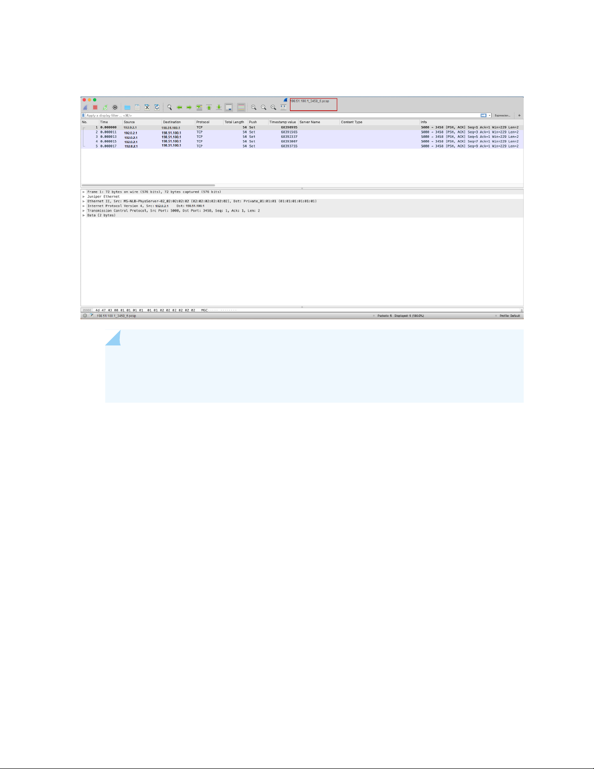
Figure 1: Sample Packet Capture File
19
NOTE: In situations where packet loss is occurring, the device may not be able to capture
all relevant details of the flow. In this case, the .pcap file will only reflect what the device was
able to ingest and process.
The security device saves the packet capture details for all traffic that matches the three match criteria
(destination IP address, destination port, and protocol) in the same file regardless of global or policy-level
configuration. The system maintains the cache with the destination IP address, destination port, and the
protocol and does not accept the repeated capturing of the same traffic which exceeds the defined limit.
You can set the packet capture file options as in packet-capture.
Verification
Viewing Packet Capture Details
Purpose
View the packet capture details to confirm that your configuration is working.
Action
Use the show services application-identification packet-capture counters command.
user@host> show services application-identification packet-capture counters
Page 20

pic: 0/0
Counter type Value
Total sessions captured 47
Total packets captured 282
Active sessions being captured 1
Sessions ignored because of memory allocation failures 0
Packets ignored because of memory allocation failures 0
Ipc messages ignored because of storage limit 0
Sessions ignored because of buffer-packets limit 0
Packets ignored because of buffer-packets limit 0
Inconclusive sessions captured 4
Inconclusive sessions ignored 0
Cache entries timed out 0
Meaning
From this sample output, you can get details such as the number of sessions being captured, and the
number of sessions already captured. For more details about the packet capture counters, see show services
application-identification packet-capture counters.
20
SEE ALSO
request services application-identification clear packet-capture all
clear services application-identification packet-capture counters
WHAT'S NEXT
For more information on application identification, see Application Identification. For details about
custom applications, see Custom Application Signatures for Application Identification
Page 21

3
CHAPTER
Control the Re-merge Behavior on Point-to-Multipoint LSP Network
How to Control the Re-merge Behavior on the Point-to-Multipoint LSP Network | 22
Page 22

How to Control the Re-merge Behavior on the Point-to-Multipoint LSP Network
22
SUMMARY
Learn how to control and change the default P2MP
sub LSP re-merge behavior in a P2MP RSVP MPLS
network.
IN THIS SECTION
Re-merge Behavior on Point-to-Multipoint LSP
Overview | 22
Re-merge Behavior on Point-to-Multipoint LSP Overview
IN THIS SECTION
Benefits of Controlling the P2MP LSP Re-merge | 22
What is P2MP LSP Re-merge? | 23
Modify the Default P2MP LSP Re-merge Behavior | 24
This section talks about the benefits and overview of controlling the re-merge behavior on RSVP
Point-to-Multipoint (P2MP) LSPs.
Benefits of Controlling the P2MP LSP Re-merge
Reduces the RSVP signalling load on the ingress (headend routers) by avoiding path computation of sub
•
LSPs which creates a re-merge condition.
Saves the network bandwidth by rejecting the P2MP sub LSP re-merge at the transit node.
•
Page 23

What is P2MP LSP Re-merge?
In a P2MP MPLS LSP network, the term re-merge refers to the case of an ingress (headend) or transit node
(re-merge node) that creates a re-merge branch intersecting the P2MP LSP at another node down the
tree. This may occur due to events such as an error in path calculation, an error in manual configuration,
or network topology changes during the establishment of the P2MP LSP.
RFC 4875 defines the following two approaches for handling the P2MP LSP re-merge:
First, the node detecting the re-merge allows the re-merge case to persist, but data from all but one
•
incoming interface is dropped at the re-merge node. This works by default without any configuration.
Second, the re-merge node initiates the pruning of the re-merge sub LSPs through signaling.
•
On Juniper Networks MX Series routers, the first approach (as defined by RFC 4875) works by default.
The second approach can be implemented by one of the following CLI configuration statements depending
upon where the Juniper Networks MX Series routers are placed (ingress node or transit node) in the P2MP
RSVP MPLS network:
23
no-re-merge—This CLI configuration statement when enabled at the ingress (headend) router avoids
•
the path computation of P2MP sub LSPs which creates a re-merge condition. When this CLI configuration
statement is configured at the ingress, then configuring the no-p2mp-re-merge CLI configuration
statement at the transit router is not required.
no-p2mp-re-merge—This CLI configuration statement when enabled at the transit router changes the
•
default behavior of allowing the P2MP sub LSP sessions re-merge to rejecting the re-merge. This CLI
configuration statement is primarily required when the ingress (headend router) is not a Juniper Networks
MX Series router.
single-abr—This command when enabled reduces re-merge condition beyond the inter-area, or
•
inter-domain, or inter-AS RSVP P2MP LSPs.
The following topology explains the re-merge behavior in a P2MP LSP network:
Page 24
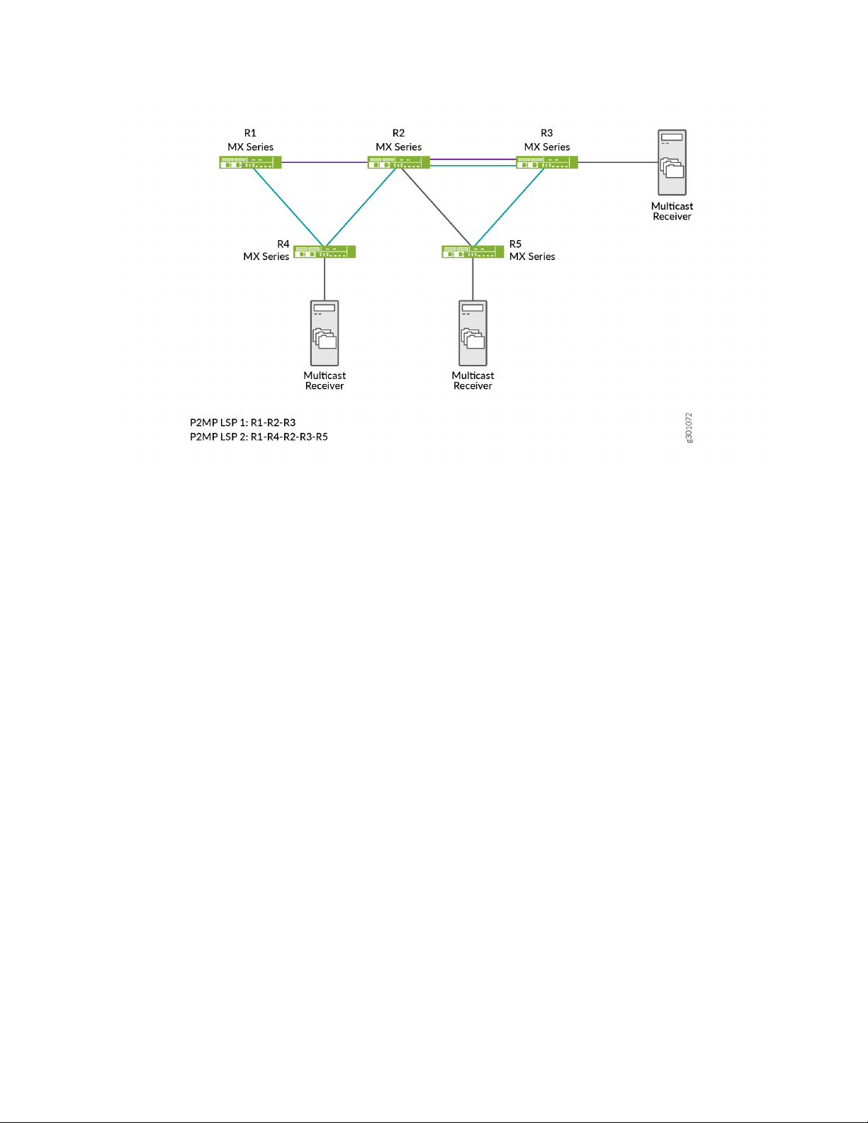
24
In this topology, R1 acts as an ingress (headend) router and R2 as the transit (re-merge node) router. There
are two sub LSP sessions created in this network, LSP 1 and LSP 2. LSP 1 is a session established among
R1, R2, and R3 devices. LSP 2 is a session established between R1, R4, R2, R3, and R5 devices. By default,
the transit router allows the re-merge to happen from both the sub LSPs and drops one of the sub LSP
branch traffic at the re-merge node. You can control this re-merge behavior by enabling the no-re-merge
CLI configuration statement at the ingress router, or the no-p2mp-re-merge CLI configuration statement
at the transit router.
If you enable the no-re-merge CLI configuration statement at the ingress router (R1), only one of the two
sub LSP sessions is established. For example, if LSP 1 (R1-R2-R3) session is established first, then the other
sub LSP session (LSP 2) will not be established.
If you enable the no-p2mp-re-merge CLI configuration statement at the transit router (R2), the transit
router rejects the re-merge of one of the sub LSPs and sends a path error message to the ingress router
(R1) preventing the ingress router from creating the second P2MP LSP re-merge branch. You can use the
show rsvp statistics CLI command to view the path error message.
Modify the Default P2MP LSP Re-merge Behavior
You can modify the default re-merge behavior either at the ingress (headend) node, or at the transit node
in a P2MP RSVP MPLS network.
On the ingress (headend router), disable the default re-merge behavior so that the ingress router does not
do the path computation of sub LSPs which creates the re-merge condition. The default behavior allows
the path computation of sub LSPs.
Page 25

[edit protocols]
user@host#set mpls p2mp-lsp no-re-merge
On the transit router, disable the default re-merge behavior so that the transit router rejects the re-merge
of sub LSPs.
[edit protocols]
user@host#set rsvp no-p2mp-re-merge
For inter-area, or inter-domain, or inter-AS RSVP P2MP LSPs, use the single-abr CLI configuration statement
at the ingress (headend router) so that all the P2MP sub LSPs prefer to select the same exit router (ABR
or ASBR), thereby reducing the re-merge condition.
[edit protocols]
user@host#set mpls p2mp-lsp single-abr
25
WHAT'S NEXT
For more information on P2MP LSPs, see Point-to-Multipoint LSP Configuration.
Page 26

4
CHAPTER
Implement Retaining the Authentication Session Using IP-MAC Bindings
How to Retain the Authentication Session Using IP-MAC Bindings | 27
Page 27

How to Retain the Authentication Session Using IP-MAC Bindings
27
SUMMARY
You can prevent the authentication session for an end
device from being terminated when the MAC address
for that device ages out.
IN THIS SECTION
Retaining the Authentication Session Based on
IP-MAC Address Bindings | 27
Retaining the Authentication Session Based on IP-MAC Address Bindings
IN THIS SECTION
Benefits | 28
CLI Configuration | 28
RADIUS Server Attributes | 29
Verification | 29
MAC RADIUS authentication is often used to permit hosts that are not enabled for 802.1X authentication
to access the LAN. End devices such as printers are not very active on the network. If the MAC address
associated with an end device ages out due to inactivity, the MAC address is cleared from the Ethernet
switching table, and the authentication session ends. This means that other devices will not be able to
reach the end device when necessary.
If the MAC address that ages out is associated with an IP address in the DHCP, DHCPv6, or SLAAC
snooping table, that MAC-IP address binding will be cleared from the table. This can result in dropped
traffic when the DHCP client tries to renew its lease.
You can configure the switching device to check for an IP-MAC address binding in the DHCP, DHCPv6,
or SLAAC snooping table before terminating the authentication session when the MAC address ages out.
Page 28

If the MAC address for the end device is bound to an IP address, then it will be retained in the Ethernet
switching table, and the authentication session will remain active.
This feature can be configured globally for all authenticated sessions using the CLI, or on a per-session
basis using RADIUS attributes.
Benefits
This feature provides the following benefits:
Ensures that an end device is reachable by other devices on the network even if the MAC address ages
•
out.
Prevents traffic from dropping when the end device tries to renew its DHCP lease.
•
CLI Configuration
Before you can configure this feature:
28
DHCP snooping, DHCPv6 snooping, or SLAAC snooping must be enabled on the device.
•
The no-mac-table-binding CLI statement must be configured. This disassociates the authentication
•
session table from the Ethernet switching table, so that when a MAC address ages out, the authentication
session will be extended until the next reauthentication.
[edit]
user@switch# set protocols dot1x authenticator no-mac-table-binding;
To configure this feature globally for all authenticated sessions:
Configure the switching device to check for an IP-MAC address binding in the DHCP, DHCPv6, or
•
SLAAC snooping table before terminating the authentication session when the MAC address ages out
using the ip-mac-session-binding CLI statement:
[edit]
user@switch# set protocols dot1x authenticator ip-mac-session-binding;
NOTE: You cannot commit the ip-mac-session-binding configuration unless the
no-mac-table-binding is also configured.
Page 29

RADIUS Server Attributes
You can configure this feature for a specific authentication session using RADIUS server attributes. RADIUS
server attributes are clear-text fields encapsulated in Access-Accept messages sent from the authentication
server to the switching device when a supplicant connected to the switch is successfully authenticated.
To retain the authentication session based on IP-MAC address bindings, configure both of the following
attribute-value pairs on the RADIUS server:
Juniper-AV-Pair = “IP-Mac-Session-Binding”
•
Juniper-AV-Pair = “No-Mac-Binding-Reauth”
•
The Juniper-AV-Pair attribute is a Juniper Networks vendor-specific attribute (VSA). Verify that the Juniper
dictionary is loaded on the RADIUS server and includes the Juniper-AV-Pair VSA (ID# 52).
If you need to add the attribute to the dictionary, locate the dictionary file (juniper.dct) on the RADIUS
server and add the following text to the file:
29
ATTRIBUTE Juniper-AV-Pair Juniper-VSA(52, string) r
NOTE: For specific information about configuring your RADIUS server, consult the AAA
documentation included with your server.
Verification
Verify the configuration by issuing the operational mode command show dot1x interface interface-name
detail and confirm that the Ip Mac Session Binding and No Mac Session Binding output fields indicate
that the feature is enabled.
user@switch> show dot1x interface ge-0/0/16.0 detail
ge-0/0/16.0
Role: Authenticator
Administrative state: Auto
Supplicant mode: Multiple
Number of retries: 3
Quiet period: 60 seconds
Transmit period: 5 seconds
Page 30

Mac Radius: Enabled
Mac Radius Restrict: Disabled
Mac Radius Authentication Protocol: EAP-MD5
Reauthentication: Disabled
Configured Reauthentication interval: 3600 seconds
Supplicant timeout: 30 seconds
Server timeout: 30 seconds
Maximum EAPOL requests: 2
Guest VLAN member: <not configured>
No Mac Session Binding: Enabled
Ip Mac Session Binding: Enabled
Number of connected supplicants: 1
Supplicant: abc, 00:00:5E:00:53:00
Operational state: Authenticated
Backend Authentication state: Idle
Authentication method: Mac Radius
Authenticated VLAN: v100
Session Reauth interval: 3600 seconds
Reauthentication due in 0 seconds
Ip Mac Session Binding: Enabled
No Mac Binding Reauth: Enabled
Eapol-Block: Not In Effect
30
Clients authenticated with MAC RADIUS should remain authenticated, and MAC address entries in the
Ethernet switching table should also be retained after expiration of the MAC timer.
WHAT'S NEXT
See Authentication Session Timeout.
Page 31

5
CHAPTER
NETCONF Sessions over Transport Layer Security (TLS)
How to Configure NETCONF Sessions over Transport Layer Security (TLS) | 32
Page 32

How to Configure NETCONF Sessions over Transport Layer Security (TLS)
32
SUMMARY
Network Configuration Protocol (NETCONF) clients
can use the Transport Layer Security (TLS) protocol
with mutual X.509 certificate-based authentication to
establish a NETCONF session with supported devices
running Junos OS.
IN THIS SECTION
Understanding NETCONF-over-TLS
Connections | 32
How to Establish a NETCONF Session over
TLS | 37
Understanding NETCONF-over-TLS Connections
IN THIS SECTION
Benefits of NETCONF over TLS | 32
NETCONF over TLS Overview | 33
Understanding the TLS Client-to-NETCONF Username Mapping | 34
NETCONF-over-TLS Connection Workflow | 36
Benefits of NETCONF over TLS
Enables remote management of devices using mutual certificate-based authentication
•
Enables you to more easily manage networks on a larger scale than when using NETCONF over SSH
•
Secures the connection and exchange of NETCONF messages
•
Uses public-key infrastructure to provide mutual TLS certificate-based authentication for both the client
•
and the server
Ensures data integrity for exchanged messages
•
Page 33

NETCONF over TLS Overview
You can establish a Network Configuration Protocol (NETCONF) session over Transport Layer Security
(TLS) on certain devices running Junos OS, as an alternative to establishing a NETCONF session over SSH.
TLS is a cryptographic protocol that uses mutual certificate-based authentication and provides a secure
and reliable connection between two devices. It is a successor to the Secure Sockets Layer (SSL) protocol.
When you establish a NETCONF session over TLS, the NETCONF server acts as the TLS server, and the
NETCONF client must act as the TLS client.
NETCONF sessions over TLS provide some advantages over sessions that use SSH. Whereas SSH
authenticates a client by using credentials (username and password) or keys, TLS uses certificates to
mutually authenticate both the client and the server. Certificates can provide additional information about
a client, and they can be used to securely authenticate one device to another. Thus, while NETCONF
sessions over SSH work well for manually managing individual devices, NETCONF sessions that use TLS
enable secure device-to-device communication for more effectively managing and automating devices in
large-scale networks.
NETCONF-over-TLS sessions on devices running Junos OS require the following:
33
NETCONF client that supports TLS version 1.2
•
The server and client must have X.509 public key certificates, and the certificates must not be self-signed
•
The Junos OS public key infrastructure (PKI) has the appropriate certificates loaded for the server and
•
for any necessary certificate authorities (CAs)
The device running Junos OS is configured for NETCONF over TLS and defines a default or specific
•
certificate-to-NETCONF-username mapping for a client
The NETCONF username corresponds to a valid Junos OS user account
•
TLS uses X.509 digital certificates for server and client authentication. A digital certificate is an electronic
means for verifying your identity through a trusted third party, known as a certificate authority or certification
authority (CA). A certificate authority issues digital certificates, which can be used to establish a secure
connection between two endpoints through certificate validation. The X.509 standard defines the format
for the certificates. To establish a NETCONF session over TLS on supported devices running Junos OS,
both the server and the client must have a valid X.509 certificate, and the certificates must be signed by
a CA. Self-signed certificates cannot be used to establish NETCONF sessions over TLS.
The Junos OS PKI provides an infrastructure for digital certificate management. To establish a TLS
connection, you must install the following in the Junos OS PKI:
NETCONF server’s local certificate and its intermediate CAs
•
NOTE: If the server certificate chain does not include intermediate CAs, you must configure
the root CA.
Page 34

NETCONF client’s root CA required to validate the NETCONF client certificate
•
After the server verifies the identity of the client and establishes the TLS connection, it must derive the
NETCONF username for that client before it can establish the NETCONF session. The NETCONF username
is the Junos OS user account under whose access privileges and permissions the NETCONF operations
are performed. You can configure a list of client certificate-to-NETCONF username mappings, and you
can also configure a default NETCONF username mapping. Junos OS uses the default mapping when a
client certificate does not match any of the configured clients. If the server extracts a valid NETCONF
username, it then establishes the NETCONF session. For more information about deriving the NETCONF
username, see “Understanding the TLS Client-to-NETCONF Username Mapping” on page 34.
The Junos OS tls-proxyd process handles the TLS connection. It performs the TLS handshake, encrypts
and decrypts the traffic, determines the NETCONF username, and fetches the authorization parameters
for the NETCONF user. The tls-proxyd process works in conjunction with the management process (mgd)
to create and manage the NETCONF session. The NETCONF-over-TLS session workflow is outlined in
“NETCONF-over-TLS Connection Workflow” on page 36.
For more information about NETCONF over TLS, see RFC 7589, Using the NETCONF Protocol over Transport
Layer Security (TLS) with Mutual X.509 Authentication.
34
For more information about the Transport Layer Security protocol, see RFC 5246, The Transport Layer
Security (TLS) Protocol Version 1.2.
Understanding the TLS Client-to-NETCONF Username Mapping
The authenticated identity of the NETCONF-over-TLS client is the NETCONF username. Junos OS executes
the NETCONF operations under the account privileges of this user. You can configure the method used
to derive the NETCONF username for individual clients, and you can also define a default method to derive
the NETCONF username for those clients that do not match a configured client.
You can configure the mapping of client certificates to NETCONF usernames at the [edit system services
netconf tls client-identity] hierarchy level. For each client, you configure the certificate fingerprint and a
map type. If the fingerprint of a client certificate matches a configured fingerprint, Junos OS uses the
corresponding map type to derive the NETCONF username. You can configure only one fingerprint per
client, and each client fingerprint must be unique. For example:
netconf {
tls {
client-identity client1 {
fingerprint
04:D2:96:AF:89:AB:33:A4:F9:5C:0F:34:9E:FC:67:2D:98:C6:08:9B:E8:6C:DE:63:60:1C:F6:CD:1A:43:5A:30:AD;
map-type specified;
username netconf-user;
}
Page 35

client-identity client2 {
fingerprint
04:95:71:45:4F:56:10:CA:B1:89:A3:8C:5D:89:CC:BD:01:37:03:EC:B5:4A:55:22:AD:49:DA:9B:D8:8B:3A:21:12;
map-type san-dirname-cn;
}
}
}
The configured certificate fingerprint uses x509c2n:tls-fingerprint format as defined in RFC 7407, A YANG
Data Model for SNMP Configuration. In this format, the first octet is the hashing algorithm identifier, and
the remaining octets are the result of the hashing algorithm. The hashing algorithm identifier, which is
shown here for reference, is defined in RFC 5246, The Transport Layer Security (TLS) Protocol Version 1.2.
md5: 1
•
sha1: 2
•
sha224: 3
•
35
sha256: 4
•
sha384: 5
•
sha512: 6
•
You can also configure a default mapping for the NETCONF username at the [edit system services netconf
tls default-client-identity] hierarchy level. If the fingerprint of a client certificate does not match any
configured clients, Junos OS uses the default map type to derive the NETCONF username.
The following map types are supported:
san-dirname-cn—Use the common name (CN) defined for the SubjectAltName’s (SAN) DirName field
•
(DirName:/CN) in the client certificate as the NETCONF username.
specified—Use the NETCONF username defined in the username statement at the same hierarchy level.
•
After the server verifies the identity of the client and establishes the TLS connection, it derives the
NETCONF username. It first matches the fingerprint for each configured client against the fingerprint of
the presented certificate. If there is a match, it uses the corresponding map type to derive the NETCONF
username. If none of the configured fingerprints match that of the client’s certificate, the default map type
is used to derive the NETCONF username.
After the server determines the username, it fetches the authorization for the user locally or remotely.
The username must either have a user account defined locally on the device, or it must be authenticated
by a Lightweight Directory Access Protocol (LDAP) server, which then maps it to a local user template
account that is defined locally on the device. If the extracted username is not a valid local or remote user,
then the TLS connection is terminated.
Page 36

NETCONF-over-TLS Connection Workflow
The device running Junos OS acts as the TLS and NETCONF server. The server listens for incoming
NETCONF-over-TLS connections on TCP port 6513. The NETCONF client, which is also the TLS client,
initiates a connection with the server on that port.
The client and server perform the following actions to establish and use the NETCONF session over TLS:
1. The client sends a TLS ClientHello message to initiate the TLS handshake.
2. The server sends a ServerHello message, the server certificate chain, and a CertificateRequest message
to request a certificate from the client.
3. The client verifies the identity of the server and sends the client certificate chain.
4. The server verifies the client certificate chain with the client’s root CA, which has been preconfigured
on the server.
5. The server derives the NETCONF username for that client.
6. If the NETCONF username is valid, the server starts the NETCONF session, and the server and client
exchange NETCONF <hello> messages.
36
7. The client performs NETCONF operations using the access privileges and permissions of the NETCONF
user.
8. The client executes the <close-session> operation to end the NETCONF session, which subsequently
closes the TLS connection.
The server fails to establish the NETCONF session over TLS in the following scenarios:
The server or client certificate is expired or self-signed
•
The client doesn’t provide a certificate
•
The client doesn’t send its intermediate CA certificates
•
The client’s root certificate authority is not configured on the server
•
The server cannot map the client certificate to a configured or default map type to derive the NETCONF
•
username
The server uses the san-dirname-cn map type to derive the NETCONF username for the client, but the
•
client’s certificate does not specify a username in the corresponding field
SEE ALSO
Understanding Certificates and PKI
Page 37

How to Establish a NETCONF Session over TLS
A configuration management server is used to remotely configure the device running Junos OS. You can
establish a NETCONF session over TLS between a configuration management server and supported devices
running Junos OS. The configuration management server is the NETCONF and TLS client, and the device
running Junos OS is the NETCONF and TLS server.
Before the client and server can establish a NETCONF session over TLS, you must satisfy the requirements
discussed in the following sections:
1.
Install TLS Client Software on the Configuration Management Server | 37
2.
Obtain X.509 Certificates for the Server and Client | 37
3.
Install the Server’s Local Certificate in the Junos OS PKI | 39
4.
Install the CA Certificates in the Junos OS PKI | 40
5.
Enable the NETCONF Service over TLS | 41
6.
Configure the TLS Client-to-NETCONF Username Mapping | 42
37
7.
Configure the Default NETCONF Username Mapping | 43
8.
Configure the User Account for the NETCONF User | 44
9.
Start the NETCONF-over-TLS Session | 45
Install TLS Client Software on the Configuration Management Server
To establish a NETCONF session using TLS, the configuration management server must first establish a
TLS connection with the device running Junos OS. Thus, the configuration management server requires
software for managing the TLS protocol. For example, you can install and use the OpenSSL toolkit, which
is a toolkit for the Transport Layer Security (TLS) and Secure Sockets Layer (SSL) protocols. It is licensed
under an Apache-style license.
For more information about OpenSSL, see https://www.openssl.org.
Obtain X.509 Certificates for the Server and Client
The TLS protocol uses X.509 public key certificates to authenticate the identity of the server and the client.
To establish a NETCONF session over TLS, both the server running Junos OS and the client must have
X.509 certificates, and the certificates must be signed by a valid certificate authority (CA). Self-signed
certificates are not accepted for NETCONF sessions over TLS.
To use OpenSSL to obtain a certificate:
1. Generate a private key.
Page 38

user@cms:~$ openssl genrsa -out client.key 2048
Generating RSA private key, 2048 bit long modulus (2 primes)
......................................................+++++
.............+++++
e is 65537 (0x010001)
NOTE: Devices running Junos OS do not support using Elliptic Curve Digital Signature
Algorithm (ECDSA) keys in NETCONF sessions over TLS.
2. Generate a certificate signing request (CSR), which contains your public key and information about
your identity.
user@cms:~$ openssl req -new -key client.key -out client.csr
38
You are about to be asked to enter information that will be incorporated
into your certificate request.
What you are about to enter is what is called a Distinguished Name or a DN.
There are quite a few fields but you can leave some blank
For some fields there will be a default value,
If you enter '.', the field will be left blank.
----Country Name (2 letter code) [AU]:
State or Province Name (full name) [Some-State]:
Locality Name (eg, city) []:
Organization Name (eg, company) [Internet Widgits Pty Ltd]:
Organizational Unit Name (eg, section) []:
Common Name (e.g. server FQDN or YOUR name) []:
Email Address []:
Please enter the following 'extra' attributes
to be sent with your certificate request
A challenge password []:
An optional company name []:
3. Send the CSR to a certificate authority (CA) to request an X.509 certificate, or sign the client CSR with
a CA to generate the client certificate, for example:
user@cms:~$ openssl x509 -req -in client.csr -CA clientRootCA.crt -CAkey clientRootCA.key
-CAcreateserial -out client.crt
Page 39

Signature ok
subject=C = US, ST = State, L = City, O = Org, CN = netconf-tls-client
Getting CA Private Key
The Junos OS public key infrastructure (PKI) provides an infrastructure for digital certificate management.
You can use the Junos OS PKI to generate the required key pair and CSR for the server’s local certificate,
or you can generate them off box. You then send the CSR to a CA to request the certificate.
For information about the Junos OS PKI and the different methods for obtaining certificates, see Digital
Certificates with PKI Overview and related documentation.
Install the Server’s Local Certificate in the Junos OS PKI
The server’s local certificate is the X.509 certificate for the device running Junos OS that is acting as the
NETCONF and TLS server. You must install the local certificate for the device in the Junos OS PKI.
To manually install the server’s local certificate on the device running Junos OS:
39
1. Copy the certificate and private key to the device running Junos OS.
2. Load the certificate from the specified file using the Junos OS PKI.
Specify the file paths to the certificate and private key or key pair, and define a unique identifier for
the certificate.
user@host> request security pki local-certificate load filename /var/tmp/server.crt key
/var/tmp/server.key certificate-id netconf-server-cert
Local certificate loaded successfully
3. (Optional) Verify the certificate.
user@host> show security pki local-certificate certificate-id netconf-server-cert
Certificate identifier: netconf-server-cert
Issued to: host, Issued by: C = US, ST = California, L = Sunnyvale, O =
ServerIntCA, CN = ServerIntCA
Validity:
Not before: 03- 6-2020 22:32 UTC
Not after: 03- 6-2021 22:32 UTC
Public key algorithm: rsaEncryption(2048 bits)
Keypair Location: Keypair generated locally
Page 40

Install the CA Certificates in the Junos OS PKI
A digital certificate is an electronic means for verifying your identity through a trusted third party, known
as a certificate authority (CA). When establishing a NETCONF session over TLS, the client and server must
have X.509 digital certificates to authenticate their identity. You must configure the root CA required to
validate the client certificate as well as any CAs required to validate the server’s local certificate in the
Junos OS public key infrastructure (PKI). This requires configuring a certificate authority profile and loading
the corresponding CA certificate and certificate revocation list (CRL) for each CA. Doing this enables Junos
OS to validate a certificate against the CA.
NOTE: If the server certificate chain does not include intermediate CAs, you must configure the
root CA. Otherwise, you only need to configure the intermediate CAs.
To manually configure a CA profile and load the corresponding CA certificate and CRL:
1. Download the CA certificates and any required CA certificate revocation lists (CRLs) to the device
running Junos OS.
40
2. Configure a trusted CA profile for each required CA, for example:
[edit security pki]
user@host# set ca-profile clientRootCA ca-identity clientRootCA
user@host# set ca-profile serverRootCA ca-identity serverRootCA
user@host# set ca-profile serverIntCA ca-identity serverIntCA
user@host# commit
3. Load the CA certificate associated with the client’s root CA profile in the Junos OS PKI, and specify
the location of the certificate file.
user@host> request security pki ca-certificate load ca-profile clientRootCA filename
/var/tmp/clientRootCA.crt
Fingerprint:
93:cc:d4:bb:ce:6b:e5:8d:91:e2:f9:46:7c:f8:a5:52:87:88:b5:28 (sha1)
03:18:f4:42:38:fd:ad:c4:73:78:06:cd:45:2a:de:e2 (md5)
Do you want to load this CA certificate ? [yes,no] (no) yes
CA certificate for profile clientRootCA loaded successfully
4. Load the CA certificates associated with the server’s CA profiles in the Junos OS PKI, and specify the
location of the certificate file.
Page 41

If the certificate chain only has a root CA, load the root CA certificate.
•
user@host> request security pki ca-certificate load ca-profile serverRootCA filename
/var/tmp/serverRootCA.crt
Fingerprint:
af:67:c6:f0:7c:2d:11:35:72:0e:c3:b3:76:ee:63:57:d4:81:a4:77 (sha1)
2a:87:1f:f8:9d:67:4c:d3:94:d2:b1:29:14:e0:90:2e (md5)
Do you want to load this CA certificate ? [yes,no] (no) yes
CA certificate for profile serverRootCA loaded successfully
If the certificate chain includes intermediate CAs, you only need to load the intermediate CA
•
certificates.
user@host> request security pki ca-certificate load ca-profile serverIntCA filename
/var/tmp/serverIntCA.crt
41
Fingerprint:
7c:a2:59:0e:6d:8b:6a:c5:da:e2:73:73:b0:cc:4a:28:39:dd:a2:52 (sha1)
57:03:85:ef:eb:e8:72:a6:70:a0:c3:c9:35:e8:6a:eb (md5)
Do you want to load this CA certificate ? [yes,no] (no) yes
CA certificate for profile serverIntCA loaded successfully
5. Load the CRL for a given CA profile where required, for example:
user@host> request security pki crl load ca-profile clientRootCA filename /var/tmp/revoke.crl
6. (Optional) Verify the CA certificate.
user@host> show security pki ca-certificate ca-profile clientRootCA detail
Enable the NETCONF Service over TLS
To enable NETCONF over TLS:
1. Configure the server’s local certificate ID, and reference the ID that was defined when the certificate
was installed.
[edit system services netconf tls]
user@host# set local-certificate netconf-server-cert
Page 42

2. Define how the server should derive the NETCONF username for a given client.
You can define the mapping for an individual client, as described in “Configure the TLS
•
Client-to-NETCONF Username Mapping” on page 42.
You can also define a default mapping that is used when a client does not match any of the configured
•
clients. See “Configure the Default NETCONF Username Mapping” on page 43.
3. (Optional) Configure trace options for NETCONF sessions over TLS, for example:
[edit system services netconf tls]
user@host# set traceoptions file size 10m
user@host# set traceoptions file files 2
user@host# set traceoptions flag all
4. Commit the configuration.
[edit system services netconf tls]
user@host# commit
42
Configure the TLS Client-to-NETCONF Username Mapping
You can define the mapping between the client certificate and the NETCONF username for specific clients.
If you do not define a mapping for a specific client, then you must define a default mapping in order for
the client to establish a NETCONF session over TLS.
To define the mapping to derive the NETCONF username for a given client:
1. Determine the fingerprint for the client’s certificate by executing the command appropriate for your
environment on the configuration management server and the format of the certificate, for example:
user@cms:~$ openssl x509 -noout -fingerprint -sha256 -in client.crt
SHA256
Fingerprint=D2:96:AF:89:AB:33:A4:F9:5C:0F:34:9E:FC:67:2D:98:C6:08:9B:E8:6C:DE:63:60:1C:F6:CD:1A:43:5A:30:AD
2. Determine the fingerprint’s hashing algorithm identifier as defined in RFC 5246, The Transport Layer
Security (TLS) Protocol Version 1.2.
This examples uses the SHA-256 hashing algorithm, which corresponds to the identifier value of 4.
md5: 1
•
sha1: 2
•
sha224: 3
•
Page 43

sha256: 4
•
sha384: 5
•
sha512: 6
•
3. On the device running Junos OS, define a unique identifier for the client.
[edit system services netconf tls]
user@host# edit client-identity client1
4. Configure the client’s certificate fingerprint in x509c2n:tls-fingerprint format.
The fingerprint’s first octet is the hashing algorithm identifier, and the remaining octets are the result
of the hashing algorithm.
[edit system services netconf tls client-identity client1]
user@host# set fingerprint
04:D2:96:AF:89:AB:33:A4:F9:5C:0F:34:9E:FC:67:2D:98:C6:08:9B:E8:6C:DE:63:60:1C:F6:CD:1A:43:5A:30:AD
43
5. Configure the map type that defines how the server derives the NETCONF username for that client.
[edit system services netconf tls client-identity client1]
user@host# set map-type (san-dirname-cn | specified)
6. If the map type is specified, configure the NETCONF username to use for that client.
[edit system services netconf tls client-identity client1]
user@host# set username netconf-user
7. Commit the configuration.
[edit system services netconf tls client-identity client1]
user@host# commit
Configure the Default NETCONF Username Mapping
You can define a default mapping that is used to derive the NETCONF username when a client does not
match a client configured at the [edit system services netconf tls client-identity] hierarchy level.
Page 44

To define the default mapping to derive the NETCONF username:
1. Configure the default map type that the server uses to derive the NETCONF username.
[edit system services netconf tls]
user@host# set default-client-identity map-type (san-dirname-cn | specified)
2. If the map type is specified, configure the default NETCONF username.
[edit system services netconf tls]
user@host# set default-client-identity username netconf-default-user
3. Commit the configuration.
[edit system services netconf tls]
user@host# commit
44
Configure the User Account for the NETCONF User
When establishing a NETCONF session over TLS, the server maps the client certificate to the NETCONF
user that performs the operations on the device for that session. Junos OS supports local users and LDAP
remote users for NETCONF-over-TLS sessions. After the TLS session is established, the server maps the
client certificate to the configured or default username specified at the [edit system services netconf tls]
hierarchy level. That username must either have a user account defined locally on the device, or it must
be authenticated by an LDAP server, which then maps it to a local user template account that is defined
locally on the device. The following instructions explain how to create a user account on devices running
Junos OS.
To create a user account for the NETCONF user on a device running Junos OS:
1. Configure the user statement with a unique username, and include the class statement to specify a
login class that has the permissions required for all actions to be performed by the user. For example:
[edit system login]
user@host# set user netconf-user class super-user
2. (Optional) Configure the uid and full-name statements to specify the user’s ID and name.
[edit system login]
user@host# set user netconf-user uid 2001 full-name "NETCONF TLS User"
Page 45

3. Commit the configuration to activate the user account on the device.
[edit]
user@host# commit
4. Repeat the preceding steps on each device running Junos OS where the client establishes NETCONF
sessions over TLS.
SEE ALSO
Junos OS User Accounts Overview
Configuring Local User Template Accounts for User Authentication
Start the NETCONF-over-TLS Session
45
The configuration management server acts as the NETCONF and TLS client. You can use any software for
managing the TLS protocol to initiate the NETCONF-over-TLS session with the device running Junos OS.
To start the NETCONF-over-TLS session:
1. Initiate the connection to the NETCONF server on port 6513, and provide the client’s certificate and
key, the root CA certificate for the server, and all intermediate CA certificates required to validate the
client certificate.
user@cms:~$ openssl s_client -connect 198.51.100.1:6513 -CAfile all_CAs -cert client.crt -key
client.key -tls1_2
CONNECTED(00000005)
...
[TLS handshake]
...
--<!- No zombies were killed during the creation of this user interface -->
<!- user netconf-user, class j-super-user -->
<hello xmlns="urn:ietf:params:xml:ns:netconf:base:1.0">
Page 46

<capabilities>
<capability>urn:ietf:params:netconf:base:1.0</capability>
<capability>urn:ietf:params:netconf:capability:candidate:1.0</capability>
<capability>urn:ietf:params:netconf:capability:confirmed-commit:1.0</capability>
<capability>urn:ietf:params:netconf:capability:validate:1.0</capability>
<capability>urn:ietf:params:netconf:capability:url:1.0?scheme=http,ftp,file</capability>
<capability>urn:ietf:params:xml:ns:netconf:base:1.0</capability>
<capability>urn:ietf:params:xml:ns:netconf:capability:candidate:1.0</capability>
<capability>urn:ietf:params:xml:ns:netconf:capability:confirmed-commit:1.0</capability>
46
<capability>urn:ietf:params:xml:ns:netconf:capability:validate:1.0</capability>
<capability>urn:ietf:params:xml:ns:netconf:capability:url:1.0?scheme=http,ftp,file</capability>
<capability>urn:ietf:params:xml:ns:yang:ietf-netconf-monitoring</capability>
<capability>http://xml.juniper.net/netconf/junos/1.0</capability>
<capability>http://xml.juniper.net/dmi/system/1.0</capability>
</capabilities>
<session-id>35510</session-id>
</hello>
]]>]]>
2. Verify that the session maps to the correct NETCONF user.
The server emits the NETCONF username for that session during the session establishment.
<!-- user netconf-user, class j-super-user -->
3. Perform NETCONF operations as necessary.
<rpc><get-configuration/></rpc>
Page 47

<rpc-reply xmlns="urn:ietf:params:xml:ns:netconf:base:1.0"
xmlns:junos="http://xml.juniper.net/junos/20.2R1/junos">
<configuration xmlns="http://xml.juniper.net/xnm/1.1/xnm"
junos:changed-seconds="1583544555" junos:changed-localtime="2020-03-07 01:29:15
UTC">
...
4. Close the NETCONF session and TLS connection.
<rpc><close-session/></rpc>
<rpc-reply xmlns="urn:ietf:params:xml:ns:netconf:base:1.0"
xmlns:junos="http://xml.juniper.net/junos/20.2R1/junos">
<ok/>
</rpc-reply>
]]>]]>
<!-- session end at 2020-03-11 19:10:28 UTC -->
closed
47
WHAT'S NEXT
For more information about NETCONF sessions on devices running Junos OS, see the NETCONF XML
Management Protocol Developer Guide.
Page 48

6
CHAPTER
Safe Search Enhancement for Web Filtering
How to Configure Web Filtering with Safe Search | 49
Page 49

How to Configure Web Filtering with Safe Search
49
SUMMARY
Learn about our safe search enhancement for Unified
Threat Management (UTM) Web filtering solutions to
enforce the safest Web browsing mode available, by
default.
IN THIS SECTION
Safe Search Enhancement for Web Filtering
Overview | 49
Configure Web Filtering with Safe Search | 51
Safe Search Enhancement for Web Filtering Overview
IN THIS SECTION
Benefits of Safe Search Enhancement for Web Filtering | 49
Features of Safe Search Enhancement for Web Filtering | 49
Limitations of Safe Search Enhancement for Web Filtering | 51
Benefits of Safe Search Enhancement for Web Filtering
Provides the safest Web browsing mode available, by default.
•
Protects the HTTPS-based search engine cache. This protection is a key security feature requirement
•
for organizations with multiple Web users in educational, financial, health-care, banking, and corporate
segments. In a campus or branch, enabling a default safe search solution for all users and blocking the
search engine cache provides secure and comfortable Web browsing.
Features of Safe Search Enhancement for Web Filtering
You use UTM Web filtering to manage Web browsing by preventing access to inappropriate Web content.
To do this, you use the following Web filtering solutions:
Redirect Web filtering
•
Page 50

Local Web filtering
•
Enhanced Web Filtering (EWF)
•
We've enhanced the safe search functionality for these UTM Web filtering solutions to provide an extremely
safe search environment for the Web user. Table 1 on page 50 describes the features of the safe search
enhancement.
Table 1: Safe Search Enhancement Features
Safe Search
Feature
Description
50
Default safe
search
By enabling the safe search enhancement feature, you enforce the safest Web browsing mode
available by default on the well-known search engines. Doing so helps those users that are not
using the strictest safe search settings.
If you enable the safe search feature on your security device, it enforces the search service to
the strictest mode by URL query rewriting, which is transparent to you. For example, when you
do a search request on the search engines Google, Bing, Yahoo, or Yandex, the safe search feature
rewrites the requested URLs to the safest search URLs.
Here're a few examples of requested and converted URLs:
Google search engine:
•
Requested URL: https://www.google.com/search?q=test
•
Converted URL: https://www.google.com/search?q=test&safe=active
•
Bing search engine:
•
Requested URL: https://www.bing.com/search?q=test
•
Converted URL: https://www.bing.com/search?q=test&adlt=strict
•
Yahoo search engine:
•
Requested URL: https://search.yahoo.com/search?q=test
•
Converted URL: https://search.yahoo.com/search?q=test&vm=r
•
Blocking search
engine cache
Yandex search engine:
•
Requested URL: https://yandex.com/search/?text=test&lr=10619
•
Converted URL: https://yandex.com/search/?text=test&lr=10619&filter=strict
•
By blocking the search engine cache on the well-known search engines, you can hide your
Web-browsing activities from other users if you are a part of an organization that has multiple
Web users in educational, financial, health-care, banking, and corporate segments.
To block the search engine cache, you configure a general URL block pattern and category for
the search engine cache service.
Page 51

You can disable the safe search option at the Web filtering-level and profile-level configurations. See
juniper-local, websense-redirect, and juniper-enhanced.
Limitations of Safe Search Enhancement for Web Filtering
For HTTP safe search enhancement, you must enable stream mode by enabling the http-reassemble
•
option at the [edit security utm default-configuration web-filtering] hierarchy level. If you don't enable
stream mode, you can't use the safe search feature. As a result, the system sends an HTTP 302 redirect
message to the user.
For HTTPS safe search enhancement, you must enable the SSL proxy service on the security policy. If
•
SSL proxy bypasses the HTTPS traffic, then the safe search feature also bypasses the HTTPS traffic.
Configure Web Filtering with Safe Search
51
SUMMARY
Use this example to configure UTM Web filtering
solutions and verify the safe search enhancement for
UTM Web filtering.
IN THIS SECTION
Requirements | 51
Overview | 52
Configuration | 52
Verification | 56
Requirements
This example uses the following hardware and software components:
An SRX Series device
•
Junos OS Release 20.2R1
•
Before you begin:
Make sure you understand how to use Web filtering to manage Web browsing. See Web Filtering
•
Overview.
Configure a Root CA Certificate. See Configuring a Root CA Certificate.
•
Page 52
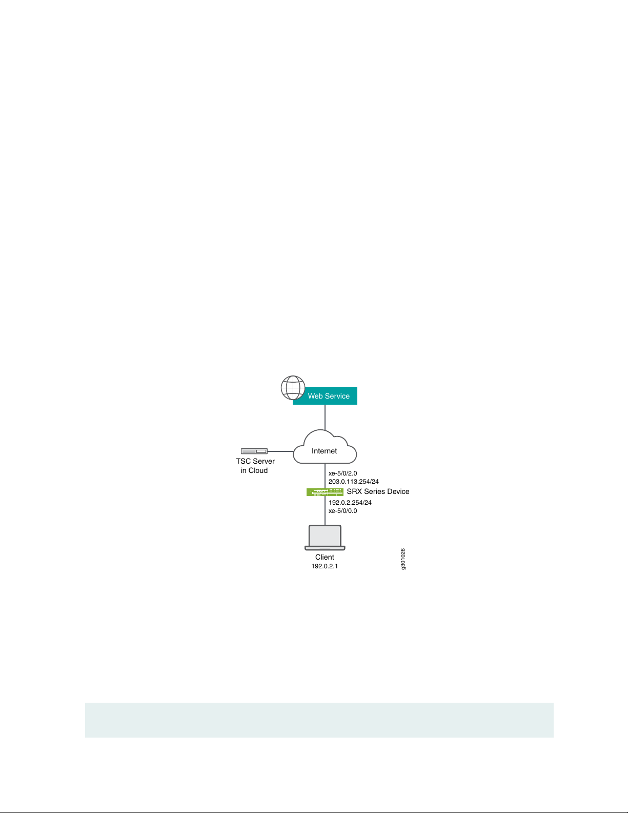
Overview
g301026
Internet
SRX Series Device
TSC Server
in Cloud
203.0.113.254/24
xe-5/0/2.0
192.0.2.254/24
xe-5/0/0.0
192.0.2.1
Client
Web Service
In this example, you configure the following policies and Web filtering profiles on your security device:
UTM policies
•
Security policies
•
Web filtering profiles
•
SSL proxy
•
After you've configured the policies and profiles, you generate the Web filtering statistics and verify the
performance of the safe search enhancement.
Figure 2 on page 52 shows the basic UTM Web filtering topology. When you enable your security device
with the safe search feature, the device rewrites the search requests from the user to the safest search
mode of the search engines. The cloud engine or the local engine performs Web filtering on the search
requests before forwarding to the Internet or external webserver.
52
Figure 2: Topology for Web Filtering Basic Function
Configuration
CLI Quick Configuration
To quickly configure this example, copy the following commands, paste them into a text file, remove any
line breaks, change any details necessary to match your network configuration, copy and paste the
commands into the CLI at the [edit] hierarchy level, and then enter commit from configuration mode.
set security utm default-configuration web-filtering type juniper-enhanced
Page 53

set security utm default-configuration web-filtering http-reassemble
set security utm default-configuration web-filtering juniper-enhanced default log-and-permit
set security utm feature-profile web-filtering juniper-enhanced profile ewf_my_profile1 category
Enhanced_Search_Engines_and_Portals action log-and-permit
set security utm feature-profile web-filtering juniper-enhanced profile ewf_my_profile1 default log-and-permit
set security utm utm-policy utmpolicy1 web-filtering http-profile ewf_my_profile1
set security policies from-zone trust to-zone internet policy sec_policy match source-address any
set security policies from-zone trust to-zone internet policy sec_policy match destination-address any
set security policies from-zone trust to-zone internet policy sec_policy match application junos-ping
set security policies from-zone trust to-zone internet policy sec_policy match application junos-http
set security policies from-zone trust to-zone internet policy sec_policy then permit application-services utm-policy
utmpolicy1
set security policies default-policy deny-all
set security zones security-zone trust host-inbound-traffic system-services all
set security zones security-zone trust host-inbound-traffic protocols all
set security zones security-zone trust interfaces xe-5/0/0.0
set security zones security-zone internet host-inbound-traffic system-services all
set security zones security-zone internet host-inbound-traffic protocols all
set security zones security-zone internet interfaces xe-5/0/2.0
set interfaces xe-5/0/0 unit 0 family inet address 192.0.2.254/24
set interfaces xe-5/0/2 unit 0 family inet address 203.0.113.254/24
53
Step-by-Step Procedure
The following example requires you to navigate various levels in the configuration hierarchy. For instructions
on how to do that, see Using the CLI Editor in Configuration Mode in the Junos OS CLI User Guide.
To configure UTM Web filtering:
1. Configure UTM Web filetring solution.
[edit security utm]
user@host# default-configuration web-filtering type juniper-enhanced
user@host# default-configuration web-filtering http-reassemble
user@host# default-configuration web-filtering juniper-enhanced default log-and-permit
user@host# feature-profile web-filtering juniper-enhanced profile ewf_my_profile1 category
Enhanced_Search_Engines_and_Portals action log-and-permit
user@host# feature-profile web-filtering juniper-enhanced profile ewf_my_profile1 default log-and-permit
user@host# utm-policy utmpolicy1 web-filtering http-profile ewf_my_profile1
2. Configure the security policies to control HTTP or HTTPS traffic from the trust zone to the Internet
zone.
[edit security policies]
Page 54

user@host# from-zone trust to-zone internet policy sec_policy match source-address any
user@host# from-zone trust to-zone internet policy sec_policy match destination-address any
user@host# from-zone trust to-zone internet policy sec_policy match application junos-ping
user@host# from-zone trust to-zone internet policy sec_policy match application junos-http
user@host# from-zone trust to-zone internet policy sec_policy then permit application-services utm-policy
utmpolicy1
user@host# default-policy deny-all
3. Configure security zones.
[edit security zones security-zone]
user@host# trust host-inbound-traffic system-services all
user@host# trust host-inbound-traffic protocols all
user@host# trust interfaces xe-5/0/0.0
user@host# internet host-inbound-traffic system-services all
user@host# internet host-inbound-traffic protocols all
user@host# internet interfaces xe-5/0/2.0
54
4. Configure interfaces.
[edit interfaces]
user@host# xe-5/0/0 unit 0 family inet address 192.0.2.254/24
user@host# xe-5/0/2 unit 0 family inet address 203.0.113.254/24
Results
From configuration mode, confirm your configuration by entering the show security policies, show security
utm, and show interfaces commands. If the output does not display the intended configuration, repeat
the configuration instructions in this example to correct it.
user@host# show security policies
from-zone trust to-zone internet {
policy sec_policy {
match {
source-address any;
destination-address any;
application [ junos-ping junos-http ];
}
then {
permit {
application-services {
Page 55

utm-policy utmpolicy1;
}
}
}
}
}
default-policy {
deny-all;
}
user@host# show security utm
default-configuration {
web-filtering {
http-reassemble;
type juniper-enhanced;
juniper-enhanced {
default log-and-permit;
}
}
}
feature-profile {
web-filtering {
juniper-enhanced {
profile ewf_my_profile1 {
category {
Enhanced_Search_Engines_and_Portals {
action log-and-permit;
}
}
default log-and-permit;
}
}
}
}
utm-policy utmpolicy1 {
web-filtering {
http-profile ewf_my_profile1;
}
}
55
user@host# show interfaces
xe-5/0/0 {
unit 0 {
Page 56

family inet {
address 192.0.2.254/24;
}
}
}
xe-5/0/2 {
unit 0 {
family inet {
address 203.0.113.254/24;
}
}
}
If you are done configuring the feature on your device, enter commit from configuration mode.
Verification
56
Verify Safe Search Function
Purpose
Verify that the safe search feature is enabled for UTM Web filtering solutions.
Action
From operational mode, enter the show security utm web-filtering statistics command to view the Web
filtering statistics. In the output, the Safe-search redirect and Safe-search rewrite fields display the
enhanced safe search redirect and rewrite statistics.
user@host> show security utm web-filtering statistics
UTM web-filtering statistics:
Total requests: 0
white list hit: 0
Black list hit: 0
No license permit: 0
Queries to server: 0
Server reply permit: 0
Server reply block: 0
Server reply quarantine: 0
Server reply quarantine block: 0
Server reply quarantine permit: 0
Custom category permit: 0
Custom category block: 0
Page 57

Custom category quarantine: 0
Custom category qurantine block: 0
Custom category quarantine permit: 0
Site reputation permit: 0
Site reputation block: 0
Site reputation quarantine: 0
Site reputation quarantine block: 0
Site reputation quarantine permit: 0
Site reputation by Category 0
Site reputation by Global 0
Cache hit permit: 0
Cache hit block: 0
Cache hit quarantine: 0
Cache hit quarantine block: 0
Cache hit quarantine permit: 0
Safe-search redirect: 0
+Safe-search rewrite: 0
SNI pre-check queries to server: 0
SNI pre-check server responses: 0
Web-filtering sessions in total: 64000
Web-filtering sessions in use: 0
Fallback: log-and-permit block
Default 0 0
Timeout 0 0
Connectivity 0 0
Too-many-requests 0 0
57
Meaning
The output displays that the safe search feature is enabled and there are no safe search redirects and safe
search rewrites.
WHAT'S NEXT
Now that you’ve learned about safe search enhancement for Web filtering, you'll be interested to know
how to disable the safe search function. Check out juniper-local, websense-redirect, and juniper-enhanced
for more information.
Page 58

7
CHAPTER
LDAP Authentication and Authorization over TLS
LDAP Authentication and Authorization over TLS | 59
Page 59

LDAP Authentication and Authorization over TLS
59
SUMMARY
Learn about LDAP authentication and authorization
over TLS (LDAPS) for Junos OS user login.
LDAP Authentication over TLS
IN THIS SECTION
Junos OS User Authentication Overview | 59
Benefits of LDAP Authentication over TLS | 60
Supported and Unsupported Features | 60
LDAP Overview | 61
IN THIS SECTION
LDAP Authentication over TLS | 59
Transport Layer Security (TLS) Overview | 61
How LDAPS Authentication Works | 61
Junos OS User Authentication Overview
Junos OS authenticates users trying to log in either locally or by using a centralized database. Local
authentication or authorization is possible for users whose username and password are configured using
the Junos OS CLI or RPCs. In Junos OS Release 20.2R1, Junos OS supports LDAP with TLS security (LDAPS)
support for user login and ensures secure transmission of data between the LDAPS client and the LDAPS
server.
In releases before Junos OS Release 20.2R1, Junos OS supports centralized user authentication and
authorization through standard RADIUS and TACACS protocols.
Page 60
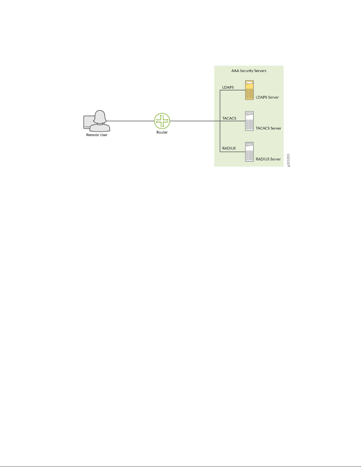
Figure 3: Centralized Authentication, Authorization, and Accounting (AAA) Setup
Junos OS supports these methods of user authentication:
60
Local password authentication
•
LDAP over TLS (LDAPS)
•
RADIUS
•
TACACS+
•
Benefits of LDAP Authentication over TLS
Encryption and data integrity—LDAPS ensures that user credentials are encrypted, thereby maintaining
•
privacy of communications. The user encrypts the data using the private key and only the intended
recipient that possesses the private key can decrypt the signed data using the signer's public key. This
ensures data integrity.
Enhanced security—The TLS protocol ensures the data is securely sent and received over the network.
•
TLS uses certificates to authenticate and encrypt the communication that provides advanced security.
Scalability—LDAPS provides greater performance and scalability without loss of reliability. There is no
•
limit to the number of users who can be supported using this feature as users maintain their own
certificates, and certificate authentication involves exchange of data between client and server only.
Supported and Unsupported Features
Junos OS supports LDAPS for user authentication and authorization only. Junos OS does not support
•
accounting. over LDAPS.
Page 61

The LDAPS client is implemented and integrated as part of Junos OS. However, implementation of the
•
LDAPS server on Junos OS is not supported. Instead, this feature is implemented using the OpenLdap
2.4.46 server.
LDAP Overview
Lightweight Directory Access Protocol (LDAP) is a standard application protocol for accessing and
maintaining distributed directory information services over an Internet Protocol (IP) network. You can
accomplish authentication and authorization using the following rich set of LDAP security functions such
as:
Search
•
Retrieve
•
Directory content manipulation
•
Transport Layer Security (TLS) Overview
61
TLS is an application-level protocol that provides encryption technology for the Internet. It is the most
widely used security protocol for applications that require data to be securely exchanged over a network,
such as file transfers, VPN connections, instant messaging, and voice over IP (VoIP). TLS relies on certificates
and private-public key exchange pairs to secure the transmission of data between the LDAPS client and
the LDAPS server. LDAPS uses local certificates that are dynamically acquired from the Junos public key
infrastructure (PKI) .
TLS ensures secure transmission of data between a client and a server effectively and ensures privacy of
communications, authentication, confidentiality, and data integrity. You can use the TLS protocol for
certificate exchange, mutual authentication, and cipher negotiation to secure the stream from potential
tampering and ethical hacking.
How LDAPS Authentication Works
To provide secure LDAPS support for Junos OS operator login, user credentials and configurations are
stored in either the LDAPS server or the LDAP-supported databases. An LDAPS client on the device
running Junos OS communicates with a configured LDAPS server. To achieve this, the LDAPS client is
implemented and integrated as part of the device running Junos OS.
Figure 4 on page 62 shows the LDAPS authentication process.
Page 62

Figure 4: LDAPS Authentication Process
2. TLS Request
3. TLS Response
4. Bind Request (binddn, bindpw)
5. Bind Successful
6. User Authentication Request (username)
7. Search Successful
8. Authentication (password) /Authorization (auth parameters) Request
9. Authentication/Authorization Successful
g301064
10. User logs in successfully
Remote User
LDAPS Client
1. Telnet/SSH
LDAPS Server
62
1. A remote user logs in to a device running Junos OS through SSH, TELNET or any other login utility.
2. The LDAPS client (which is the device running Junos OS) establishes a TCP connection with the LDAPS
authorization server using a TLS protocol request.
3. After the client receives the TLS response, the client and server authenticate their identities.
4. The LDAPS client authenticates itself using the proxy account that is preconfigured on the LDAPS
server using the bind request (binddn and bindpw).
5. If the bind operation is successful, the LDAPS server sends an acknowledgment to the LDAPS client.
6. The LDAPS client then sends an authentication request to the LDAPS server with the login credentials
of the user trying to log in.
7. After successful authorization, the LDAPS client notifies the user of the successful login. The
authorization data of the user is saved into a file that is used later to enforce authorization.
8. The client closes the connection with the LDAPS server.
WHAT'S NEXT
Page 63

For more information on LDAP Authentication over TLS, see Configure LDAP Authentication over TLS.
63
 Loading...