

Page 1
1. Read all of these instructions before
installing fixture.
2. Keep these instructions in a safe place
for future reference
3. Only qualified electricians in accordance
with local codes should perform all installations.
4. WARNING: PRIOR TO INSTALLATION
MAKE SURE ELECTRICAL POWER
SUPPLY FOR INSTALLATION CIRCUIT
IS SHUT DOWN AT ELECTRICAL
SERVICE PANEL BEFORE STARTING
INSTALLATION. DO NOT RE-ENERGIZE CIRCUIT UNTIL INSTALLATION
IS FULLY COMPLETED.
5. Fixture is designed to be electrically
grounded. WARNING: TO PREVENT
SHOCK CLOSELY FOLLOW GROUNDING DIRECTIONS.
TO ELECTRICALLY FEED FIXTURE
Electrical power can be brought to the fixture
with Non-Metallic Cable (NM) or Armored
Cable (BX) using electrical connector at fixture knockouts.
INSTALLATION INSTRUCTIONS
FLUORESCENT LIGHT FIXTURE
1. Remove the corrugated packing
sleeve(s) that surrounds the bulb before
installation.
2. Select a suitable dry mounting location
(indoor use only) capable of supporting
the fixture. DO NOT MOUNT OVER
SINK OR STOVE. Remove the lens
cover and bulb.
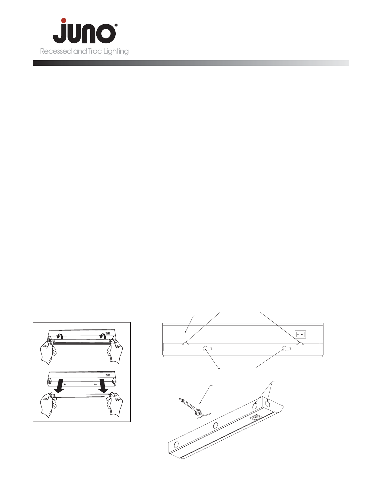
3. Remove the bulb from the fixture by
placing your thumbs on the metal ends
of the bulb. While applying slight pressure on the bulb, roll the lamp toward
you until the contact pins on the ends of
the lamp disengage from the socket. Set
aside during wiring and mounting.
WIRING CONNECTIONS - ARMORED
CABLE (BX) OR NON-METALLIC CABLE
(NM)
1. Displace cover at attachment tabs and
disengage to gain access to internal
wiring.
2. Mount die-cast aluminum electrical connector at desired fixture knockout opening. Securely tighten nut.
3. Push cable into connector. If using BX
cable, make sure BX cable has a properly installed plastic insulating bushing (not
provided). Tighten clamp screws securely
making sure that cable remains fully seated in connector during tightening.
4. Connect supply wires to fixture leads
using wire nuts provided. Black to Black,
White to White, Green to Green or bare
copper.
5. Re-attach cover. Make certain wires are
properly positioned to prevent damage.
Make certain cover is properly secured
underneath all attachment tabs to maintain ground.
NOTE: In some BX installations there may not
be a separate grounding wire provided.
Grounding is achieved through the spiral
wound metal jacket of the BX cable. For NM
installations, the NM cable must have a
ground wire properly wired to the fixture.
IMPORTANT SAFEGUARDS:
When using electrical equipment, always adhere to basic safety precautions including the following:
IMPORTANT SAFETY/ OPERATING INSTRUCTIONS
INSTALLATION INSTRUCTIONS
Fluorescent Undercabinet Lighting
UFL Fluorescent Luminaires
SAVE THESE INSTRUCTIONS
For use with 120V, 60Hz electrical power supply only.
WARNING: TO PREVENT OVERHEATING AND ELECTRICAL SHOCK DO NOT INSTALL IN SMALL ENCLOSED
SPACES. TO PREVENT ELECTRICAL SHOCK DO NOT INSTALL IN WET ENVIRONMENTS.
P2389 pg 1 of 2
COVER
ATTACHMENT TABS
KEYHOLE SLOTS
BX OR NM CABLE
INSTALLATION
MULTIPLE KNOCKOUTS
FOR REAR, END, OR TOP
FEEDING
Page 2
INSTALLATION INSTRUCTIONS
WARRANTY
Juno Lighting Group warrants that its products are free from defects in material and workmanship. Juno Lighting Group’s obligation
is expressly limited to repair or replacement, without charge, at Juno Lighting Group’s factory after prior written return authorization has been
granted. This warranty shall not apply to products which have been altered or repaired outside of Juno Lighting Group’s factory. This warranty is in
lieu of all other warranties, expressed or implied, and without limiting the generality of the foregoing phrase, excludes any implied warranty of merchantability. Also, there are no warranties which extend beyond the description of the product on the company’s literature setting forth terms of
sale.
Product Services Phone (888) 387-2212
1300 S. Wolf Rd • Des Plaines, IL 60018 • Phone: 800-323-5068 • www.junolightinggroup.com
© 2012 Juno Printed in USA Rev 4/12 P2389 pg 2 of 2
Fluorescent Undercabinet Lighting
UFL Fluorescent Luminaires
SAVE THESE INSTRUCTIONS
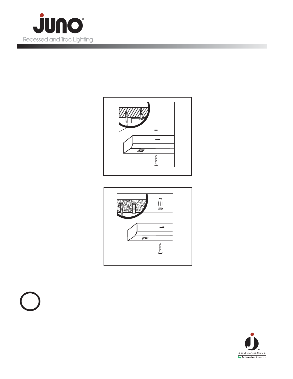
DRYWALL MOUNT
WOOD MOUNT
FOR MOUNTING ONTO WOOD OR METAL
1. Place fixture up to mounting surface and
mark position of keyhole slot on the
mounting surface with a pencil. The
screw hole locations must be exact for
the fixture to mount properly.
2. Mounting surface for the fixtures should
be minimum of 3/8˝ thick wood.
3. Drill a pilot hole just smaller than the
screw diameter. Drive screws into pilot
holes until approximately 1/8˝ of space
remains under the head of the screw.
Align keyhole slots in fixture with the two
mounting screws and slide into place so
that the screw heads are positioned within the narrow end of the slots. Tighten
screws securely.
FOR MOUNTING ONTO DRY WALL
1. Drill a pilot hole just smaller than the
anchor. Push the anchor into the hole
until it is flush with the mounting surface
and start the screws.
2. When approximately 1/8˝ of space
remains under the head of the screw,
align keyhole slots in fixture with the two
mounting screws and slide into place.
Tighten screws securely.
Once wiring and mounting is complete,
replace lamp and plastic lens, restore power at
appropriate electrical service panel.
MARK MEANS LAMP CONTAINS MERCURY.
FOLLOW DISPOSAL LAWS.
SEE WWW.LAMPRECYCLE.ORG
Hg
 Loading...