

Page 1

T
®
Trac 12/25
Installation Instructions
For Juno TLR Series Connectors and Feeds
Important Safety Instructions-Save these Instructions
1.Read all of these installation instructions before installing the trac system.
2.Do not install this trac in damp or wet locations.
3.Do not install any fixture assembly closer than 6" from any curtain or similar combustible
material.
4.Disconnect electrical power before adding to or changing the configuration of the trac.
5.Do not attempt to energize anything other than lighting fixtures on the trac. To reduce the
risk of fire or electrical shock, do not attempt to connect power tools, extension cords,
appliances and the like to the trac.
6.Power to this trac system is to be supplied by either Juno 12V transformers (TL544N and
TL547 [remote mounted only], TL548, TL549, TL550, TL554, TF5150, TF5300, TF5300-277,
TF5600, TF5600-277, TF6150E, TF6300) or 24V transformers (TL551, TL552, TL553, TF5600-24V,
TF5600277-24V, TF51200-24V, TF51200277-24V). Check with a qualified electrician before
wiring trac. If 25 amps is exceeded anywhere in the installed trac system, an overload
will occur, resulting in a potential fire.
7.These feeds and connectors are to be used with Juno TLR series trac systems only. Use
only fixtures intended for use with Juno TL or TLR series trac.
8.Save these instructions and refer to them when additions to or changes in the trac
configuration are made.
WARRANTY
Juno warrants that its products are free from defects in material and workmanship. Juno’s obligation is expressly limited to repair or replacement, without
charge, at Juno’s factory after prior written return authorization has been granted. This warranty shall not apply to products which have been altered or
repaired outside of Juno’s factory. This warranty is in lieu of all other warranties, express or implied, and without limiting the generality of the foregoing phrase,
excludes any implied warranty of merchantability. Also, there are no warranties which extend beyond the description of the product on the company ’s
literature setting forth terms of sale. Product Services phone (888) 387-2212
© 2003 Juno Printed in USA Juno lighting, inc 1300 S. Wolf Road Des Plaines, IL 60017 Visit us at www.junolighting.com P2505 rev 1 Pg 1 of 4
NOTES:
** This low voltage trac lighting system must be wired in accordance to national
and/or local codes using approved Class 1 wiring methods when applicable. Check
with a qualified electrician before installing.
** All wire retaining set screws on terminal block connectors must be tightened to 12 to
18 in-lbs (1 to 1.5 ft-lbs) to ensure reliable and safe operation.
** The terminal block used on all Trac 12/25 (TLR series) feeds and connectors is
compatible with a minimum of 18 AWG thru a maximum of 6 AWG solid or stranded wire.
The use of any field-installed wire that does not fall within this range or is not suitable for
the level of the transformer output voids the Juno warranty and poses a possible safety
hazard.
Page 2
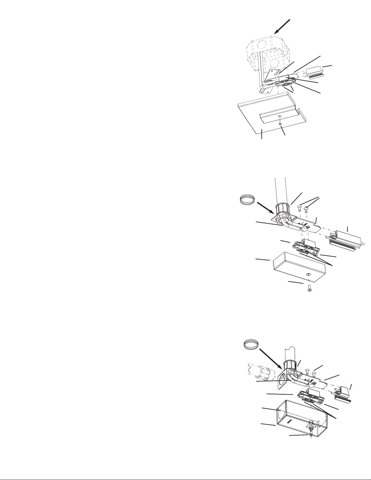
TLR21
TLR38
P2505 rev 1 Pg 2 of 4
TLR34
TLR21 Junction Box End Feed
Used to make electrical connection to a remote mounted low voltage transformer. The TLR21 mounts to
various junction boxes.
1. Pull transformer secondary wires out of junction box and strip off 5/16” of insulation from both.
2. Remove the connector cover by loosening screw.
3. Loosen the (4) set-screws in the terminal block to allow wire entry and loosen the pointed screw which
fastens the connector to the trac.
4. Insert the transformer secondary wires into the terminal block openings on the strap side as shown, and
tighten the (2) set screws until wires are snug.
5. Orient the mounting strap so the mounting holes line up with the junction box holes and the terminal
block is in-line with the trac.
6. Verify the trac has from 3/8”-7/16” of buss wire extending past the end. Slide the connector so the
mounting plate slides into the channel in the top of the trac. Hold firmly together and tighten the pointed
screw until snug.
7. Tighten the trac to the corresponding surface, then fasten the connector mounting strap to the
junction box, and tighten.
8. To make electrical connection to the buss, tighten the (2) set-screws closest to the trac to 12 to 18 in-lb
(1 to 1.5 ft-lb). Tighten the set-screws retaining the transformer wires to 12 to 18 in-lb.
9. Reinstall the cover by placing over the terminal block assembly and tightening the screw removed in
step 1 into the last terminal block hole as shown.
TLR34 Conduit End Feed Connector
Used to make electrical connection to a remote mounted low voltage transformer. The TLR38
accepts (1) electrical fitting for a 1/2” trade size knockout from the top or from the back.
1. Remove connector cover by loosening screw.
2. Remove terminal block from mounting plate by removing the (2) screws on top of the plate.
3. Connect the 1/2” electrical fitting to the mounting plate from the top (metal knockout in plate
must be removed) or from the back (plastic tear out on cover must be removed). Take note that
the plastic spacer is installed over the fitting on the top side of the plate to reduce the amount of
fitting protruding into the connector.
4. Route wires towards the front of the mounting plate as shown. Cut and strip the wires to length
per the plate markings.
5. Bend the wires slightly away from the plate and insert them into the corresponding terminal
block opening. Set-screws may have to be loosened to allow wire to be inserted. (Note: terminal
block is to be positioned with the pointed screw opposite wire entry). Tighten the (2) terminal block
set-screws until snug to retain the wires.
6. Position the terminal block (with wires attached) so the terminal block holes line up with the
holes in the mounting plate. Fasten to the mounting plate with the screws removed in step 2.
7. Loosen the (2) set-screws on the open side of the terminal block (enough to allow the buss-wire
to enter the terminal block) and loosen the pointed screw which fastens the connector to the trac.
8. Verify the trac has from 3/8”-7/16” of buss wire extending past the end. Slide the connector so
the mounting plate slides into the channel in the top of the trac. Hold firmly together and tighten
the pointed screw until snug.
9. To make electrical connection to the buss, tighten the (2) set-screws closest to the trac to 12 to
18 in-lb (1 to 1.5 ft-lb). Tighten the set-screws retaining the transformer wires to 12 to 18 in-lb.
Reinstall the cover by placing over terminal block assembly and tightening the screw removed in
step 1.
TLR38 End Feed Connector
Used to make electrical connection to a remote mounted low voltage transformer. The TLR38
accepts (1) electrical fitting for a 1/2” trade size knockout from the top.
1. Remove connector cover by loosening screw.
2. Remove terminal block from mounting plate by removing the (2) screws on top of the
plate.
3. Connect the 1/2” electrical fitting to the mounting plate. Take note that the plastic spacer
is installed over the fitting on the top side of the plate to reduce the amount of fitting
protruding into the connector.
4. Bend wires so they form a 90
o
angle towards the front of the mounting plate as shown. Cut
and strip the wires to length per the plate markings.
5. Bend the wires slightly away from the plate and insert them into the corresponding terminal
block opening. Set-screws may have to be loosened to allow wire to be inserted. (Note:
terminal block is to be positioned with the pointed screw opposite wire entry). Tighten the (2)
terminal block set-screws until snug to retain the wires.
6. Position the terminal block (with wires attached) so the terminal block holes line up with the
holes in the mounting plate. Fasten to the mounting plate with the screws removed in step 2.
7. Loosen the (2) set-screws on the open side of the terminal block (enough to allow the busswire to enter the terminal block) and loosen the pointed screw which fastens the connector
to the trac.
8. Verify the trac has from 3/8”-7/16” of buss wire extending past the end. Slide the connector
so the mounting plate slides into the channel in the top of the trac. Hold firmly together and
tighten the pointed screw until snug.
9. To make electrical connection to the buss, tighten the (2) set-screws closest to the track to
12 to 18 in-lb (1 to 1.5 ft-lb). Tighten the set-screws retaining the transformer wires to 12 to 18
in-lb.
10. Reinstall the cover by placing over terminal block assembly and tightening the screw
removed in step 1.
Compatible with:
3 1/4” Octagon or Round J-Box
4” Octagon or Round J-Box
Plaster Ring J-Box Covers
Handy Boxes
Switch Boxes
Fitting
Spacer
Terminal
Block
Mounting
Plate
Trac
Cover Screw
Cover
Pointed
Screw
Terminal
Block
Fitting
Cover
Cover Screw
Breakout
Mounting
Screws
Cover
Cover Screw
Trac
Mounting
Strap
Set Screws
Terminal
Block
Pointed Screw
Mounting
Plate
Mounting
Screws
Wires
Set Screws
Wires
Spacer
Mounting
Plate
Pointed
Screw
Set Screws
Trac
Page 3
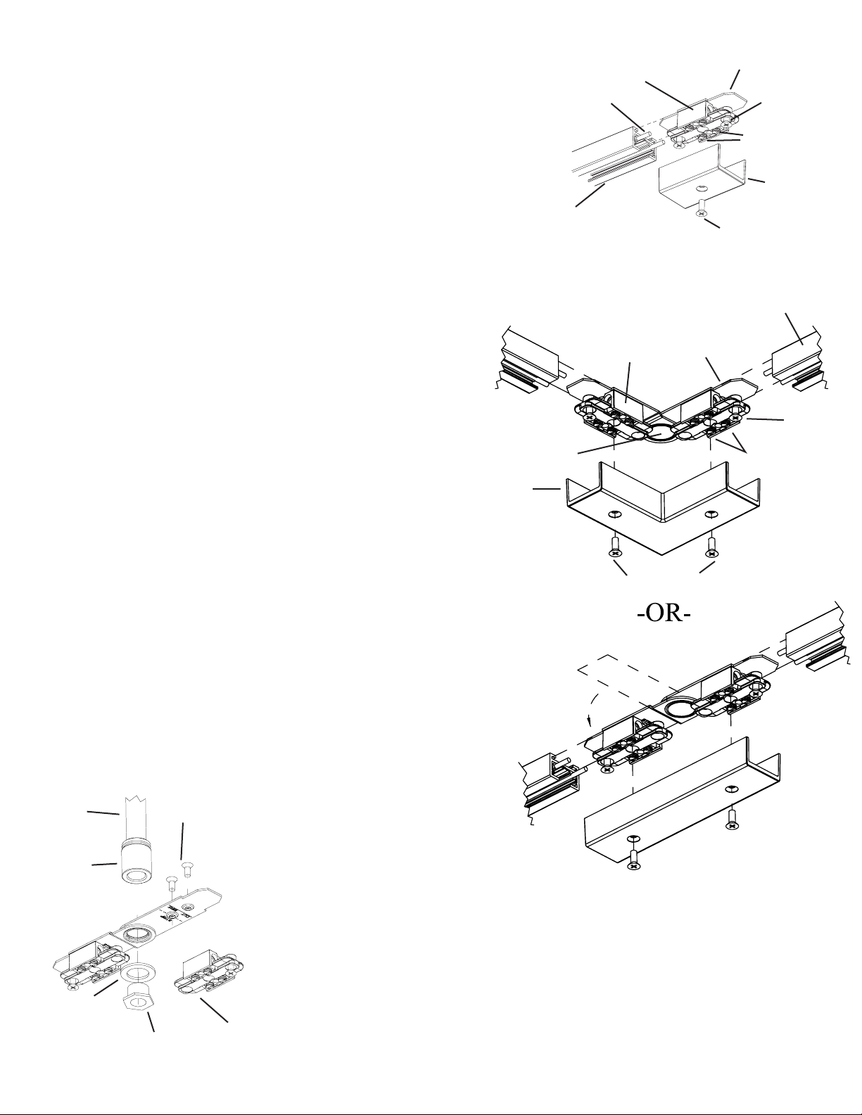
TLR23
TLR24
P2505 rev 1 Pg 3 of 4
TLR23 Miniature Straight Connector
Joins 2 track sections end-to-end to continue a straight run.
1. Remove connector cover by loosening screw.
2. Back off the (2) pointed screws in the outboard terminal block holes to allow
insertion into the trac.
3. Loosen the (4) set-screws enough to allow the buss-wire to enter the terminal
block.
4. Verify the trac has from 3/8”-7/16” of buss wire extending past the end. Slide
the connector so the metal mounting plate slides into the channel in the top of
the trac extrusion. Hold firmly together and tighten the pointed screw until
snug.
5. To make electrical connection to the buss, tighten the (2) set-screws closest
to the trac to 12 to 18 in-lb (1 to 1.5 ft-lb)
6. Repeat steps 4 & 5 to connect the other trac section.
7. Reinstall the cover by placing over terminal block assembly and tightening
screw removed in step 1.
TLR24 Adjustable Connector
Joins 2 trac sections to form a 90ocorner or a straight coupling in
surface mount or pendant mount applications.
1. Remove connector cover by loosening cover screws.
2. Back off the (2) pointed screws in the outboard terminal block
holes to allow insertion into the trac.
3. Loosen the (2) set-screws in both terminal blocks where the busswires will enter the terminal blocks (4 total). Do not loosen the setscrews that retain the jumper wires.
4. Depending on the desired application (straight or 90
o
) rotate the
connector to the corresponding position and discard the unused
cover (see illustrations).
5. Verify the trac has from 3/8”-7/16” of buss wire extending past the
end. Slide the connector so the metal mounting plate slides into the
channel in the top of the trac extrusion. Hold firmly together and
tighten the pointed screw until snug.
6. To make electrical connection to the buss, tighten the (2) setscrews closest to the trac to 12 to 18 in-lb (1 to 1.5 ft-lb)
7. Repeat steps 5 & 6 to connect the other trac section.
8. Verify that the set-screws that retain the factory installed jumper
wires are tightened to 12 to 18 in-lb (1 to 1.5 ft-lb).
9. Reinstall the corresponding cover (90
o
or straight) by placing over
connector assembly and tightening the (2) screws removed in step 1.
The TLR24 adjustable connector can also be used to support the trac in a pendant mount application
(in 90
o
& straight configurations).
A. Install the TLR series pendant mounting kit per the installation instructions included with the kit.
B. Follow the TLR24 instructions in steps 1-4 above.
C. Remove the (2) screws holding (1) of the terminal blocks to the mounting plate and rotate the
terminal block out if the way to access the hole plug. (Do not remove the jumper wires) Remove and
discard hole plug. (see illustration)
D. Fasten the TLR24 to the pendant mounting kit using the components shown. Bend the loose terminal
block back to the original position and fasten to the plate.
E. Continue installation according to steps 5-9 above.
Trac
Pointed
Screw
Cover Screw
Cover
Mounting
Plate
Terminal
Block
Buss Wire
Set Screws
Terminal
Block
Mounting
Plate
Trac
Cover
Cover Screws
Mounting Screws
Washer
Hex Bushing
Coupling
Stem
Note: Jumper wires removed for clarity
Note: Jumper wires removed for clarity
Plug
Set Screws
Pointed
Screw
Terminal
Block
Page 4
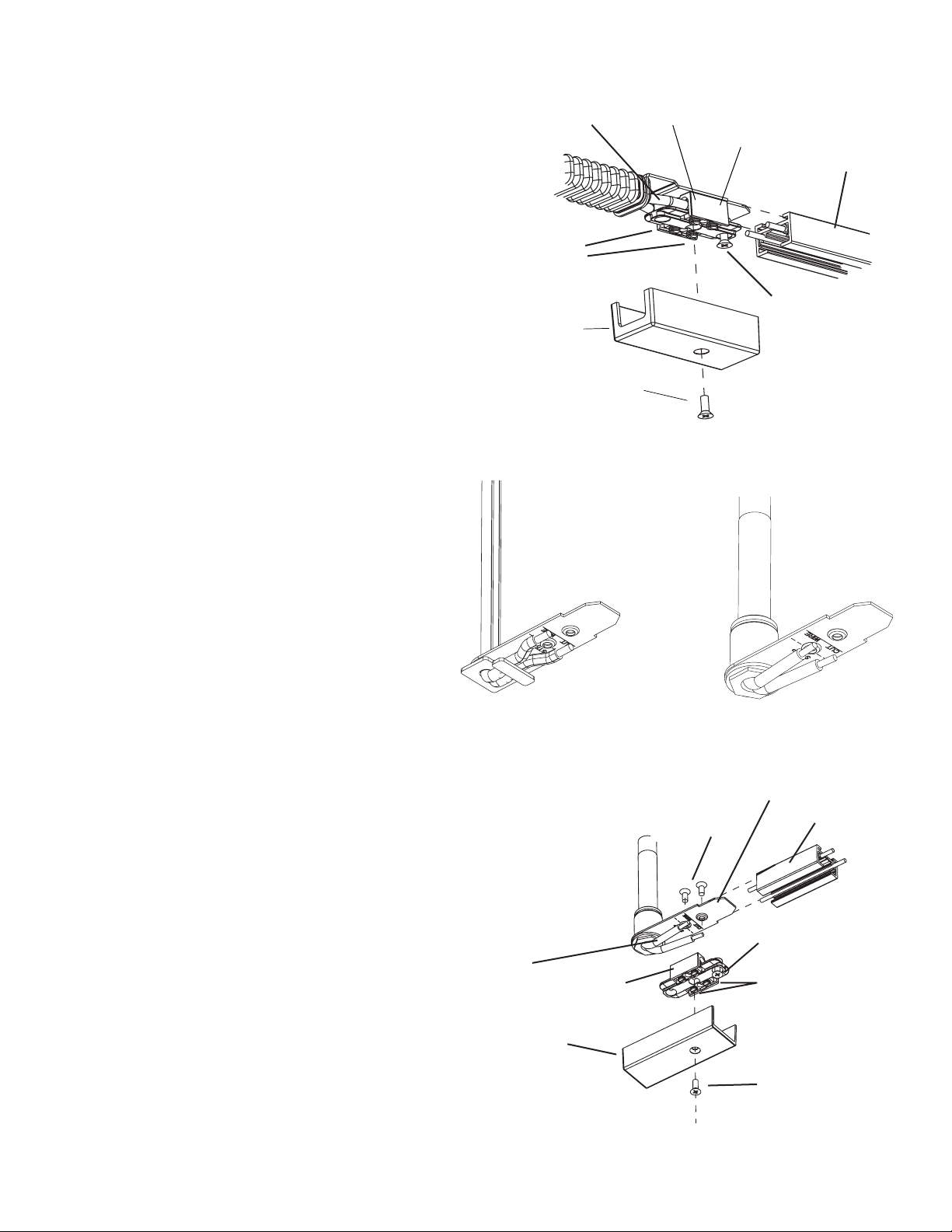
TLR20
© 2003 Juno Printed in USA Juno lighting, inc 1300 S. Wolf Road Des Plaines, IL 60017 Visit us at www.junolighting.com P2505 rev 1 Pg 4 of 4
TLR20 Adjustable Joiner
Joins 2 track sections at variable angles to left, right, up, or down to
continue a run.
1. Remove connector covers by loosening screws.
2. Back off the (2) pointed screws in the outboard terminal block holes
to allow insertion into the trac.
3. Loosen the (2) set-screws in both terminal blocks where the buss-wires
will enter the terminal blocks (4 total). Do not loosen the set-screws that
retain the jumper wires.
4. Verify the trac has from 3/8”-7/16” of buss wire extending past the
end. Slide the connector so the metal mounting plate slides into the
channel in the top of the trac extrusion. Hold firmly together and tighten
the pointed screw until snug.
5. To make electrical connection to the buss, tighten the (2) set-screws
closest to the trac to 12 to 18 in-lb (1 to 1.5 ft-lb)
6. Repeat steps 4 & 5 to connect the other trac section on the opposite
side of connector.
7. Verify that the (4) set-screws that retain the factory installed jumper
wires are tightened to 12 to 18 in-lb (1 to 1.5 ft-lb).
8. Reinstall the covers by placing over terminal block assembly and
tightening screws removed in step 1.
TLR50 Pendant End Feed
For use in conjunction with TLR series pendant mounting
kits. The TLR50 is used to support and/or feed the trac.
when pendant mounting.
1. Install the TLR series pendant mounting kit per the
installation instructions included with the kit.
2. Remove connector cover by loosening screw.
3. Remove the terminal block from the mounting plate
by removing the (2) screws on top of the plate.
4. Fasten the pendant mounting kit to the TLR50
mounting plate as shown (see pendant mounting kit
directions for further clarification).
5. Bend wires so they form a 90
o
angle towards the front
of the mounting plate as shown. Cut and strip the wires
to length per the plate markings.
6. Bend the wires slightly away from the plate and insert
them into the corresponding terminal block opening.
Set-screws may have to be loosened to allow wire to
be inserted. (Note: terminal block is to be positioned
with the pointed screw opposite wire entry). Tighten the
(2) terminal block set-screws until snug to retain the
wires.
7. Position the terminal block (with wires attached) so
the terminal block holes line up with the holes in the
mounting plate. Fasten to the mounting plate with the
screws removed in step 3.
8. Loosen the (2) set-screws on the open side of the
terminal block (enough to allow the buss-wire to enter
the terminal block) and loosen the pointed screw which
fastens the connector to the trac.
9. Verify the trac has from 3/8”-7/16” of buss wire
extending past the end. Slide the connector so the
mounting plate slides into the channel in the top of the
trac. Hold firmly together and tighten the pointed screw
until snug.
10. To make electrical connection to the buss, tighten
the (2) set-screws closest to the trac to 12 to 18 in-lb (1
to 1.5 ft-lb). Tighten the set-screws retaining the
transformer wires from the pendant kit to 12 to 18 in-lb.
11. Reinstall the cover by placing over terminal block
assembly and tightening the screw removed in step 2.
Connection to Pendant Kits
-OR-
TLR96 feed TLR90 & TLR91 feed
TLR50
Pointed Screw
Set Screws
(Typical for both sides of connector)
Mounting Screws
Cover
Cover Screw
Jumper Wires
Trac
Wires
Set Screws
Terminal BLock
Pointed Screw
Trac
Mounting Plate
Cover
Cover Screw
MountingPlate
Terminal Block
 Loading...