

Page 1
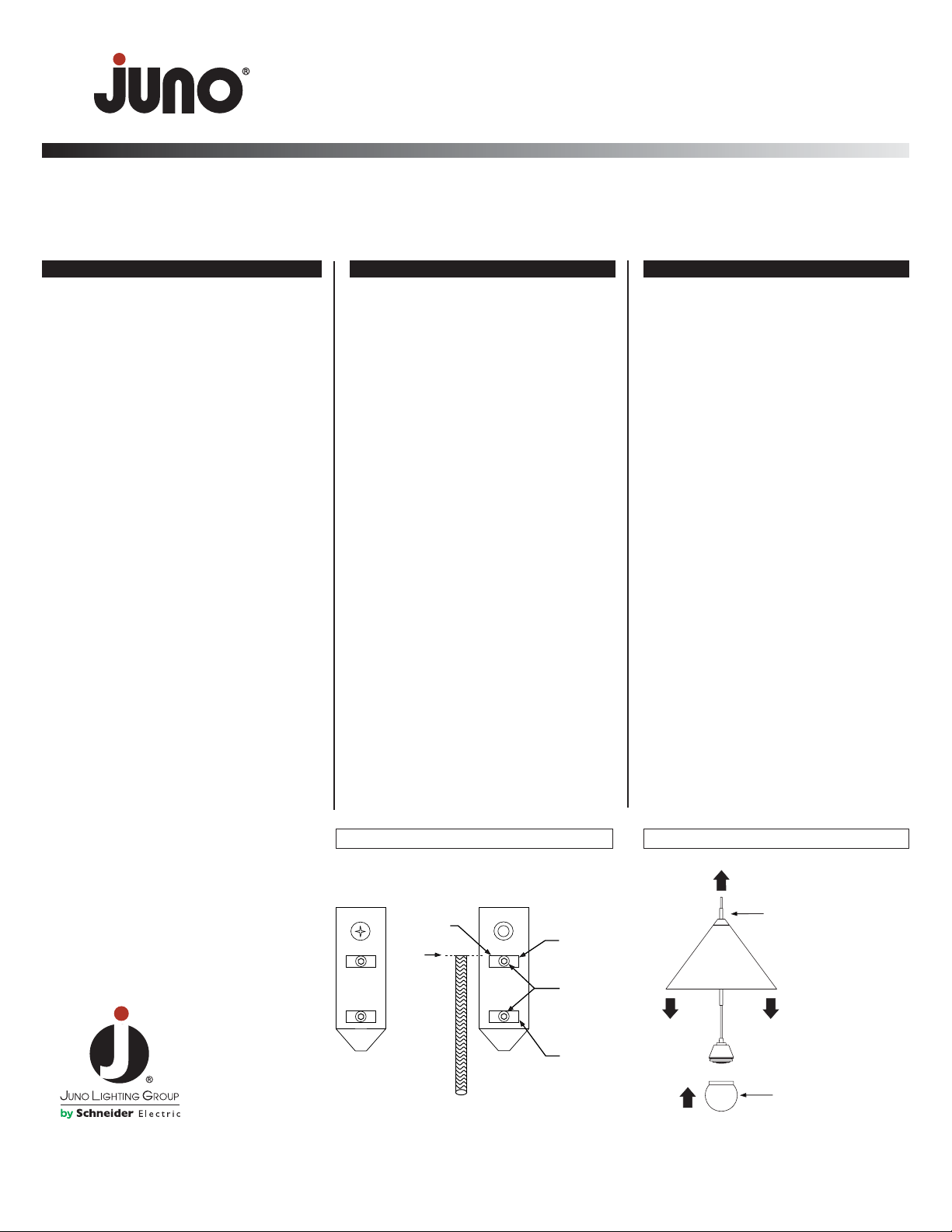
Step 7. Remove screw and cover
from SPLICE COMPARTMENT.
Step 8. With hex key (allen wrench)
provided, loosen set screws on
UPPER AND LOWER TERMINALS.
Remove cord.
Step 9. Slide cord sleeve tube
towards stripped end of wire until
stripped end just disappears into
tube. DO NOT FULLY REMOVE
TUBE FROM CORD.
Step 10. Using cord sleeve tube as
a threading device insert tube into
bottom of shade and thread through
hole in top of shade (or through
center hole in spider-type shades).
Simultaneously push wire up through
shade while pulling on cord sleeve
tube.
Step 11. Push/Pull on cord until it is
completely through the cord sleeve
tube.
Step 12. IF NOT SHORTENING
CORD, PROCEED TO STEP 20.
Caution: To reduce the risk of fire and electric shock use these products only with the appropriate Juno trac system or monopoints.
FOR USE WITH EITHER HALOGEN OR LED FIXTURES.
WARNING: Make sure power is off before assembly.
IMPORTANT SAFETY INSTRUCTIONS
ASSEMBLING CORD SET TO SHADE
Step 1. Read all instructions completely
before beginning installation. Keep
these instructions in a safe place for
future reference.
Step 2. To reduce the risk of fire and
burns, do not install pendant cords
where the exposed conductor can be
shorted or contact any conductive
material.
Step 3. Do not install any shade closer
then 6 inches (15.25 cm) from any curtain or similar combustible materials.
Step 4. To reduce the risk of fire and
overheating make sure all connections
are tight.
Step 5. Turn off the electrical power
before modifying the lighting system
in any way.
Step 6. Qualified electricians, in accor-
dance with local electrical codes should
perform all installations.
SAVE THESE INSTRUCTIONS
SHORTENING CORD SET
Step 13. Determine cord length desired
by holding cord set alongside installed,
not electrically energized splice
compartment. Cut cord at point level
with top edge of UPPER TERMINAL.
Step 14. Remove adapter from trac
or monopoint.
STEPS: 8, 9, 13
UPPER
TERMINAL
SET
SCREWS
LOWER
TERMINAL
CUT
TO EDGE
OF UPPER
TERMINAL
SPLICE COMPARTMENT
STEPS: 10, 11, 12
© 2010 Juno Lighting, LLC. Rev 4/10 P2830 pg 1 of 2
Product Services Phone (888) 387-2212
1300 South Wolf Road • Des Plaines, IL 60018 • Phone 800-323-5068 • www.junolightinggroup.com
FOR TP, TLP AND TFP LED PENDANT CORD SETS
INSTALLATION INSTRUCTIONS
CAUTION
ELECTROSTATIC
DISCHARGE SENSITIVE
This product uses components that can
be damaged by electrostatic discharge
(ESD). Do not remove diffuser ball or
touch without proper grounding.
Using CORD SLEEVE as a
threading device pass cord
through shade.
Simultaneously push & pull
sleeve and cord through
fixture.
DIFUFUSER BALL (provided)
MUST be installed.
Page 2

Step 15. Push back OUTER BRAIDED CONDUCTOR
enough to allow it to expand in diameter.
Step 16. Using a small pair of scissors snip a slit in the
OUTER BRAIDED CONDUCTOR lengthwise along the cord
1/2” long.
Step 17. Pull OUTER BRAIDED CONDUCTOR off and to
the side of the inner conductor and snip off braided conductor as squarely as possible.
Step 18. Using fingers, tightly wrap OUTER BRAIDED
CONDUCTOR around insulation of INNER CONDUCTOR.
When finished, 1/2” of the insulated INNER CONDUCTOR
should remain visible.
Step 19. With pliers hold onto cord at point shown in
illustration below. Strip insulation off of INNER
CONDUCTOR 1/4”. Twist wires into tight bundle.
Step 20. CAUTION: Inspect and trim any loose wires from
the OUTER BRAIDED CONDUCTOR to make sure they
cannot in any way make electrical contact with the exposed
end of the INNER CONDUCTOR.
Step 21. Slowly and gently insert stripped end of cord set
into both terminals. Slight left-and-right rotation of wires can
simplify this operation.
Step 22. Make sure exposed end of INNER CONDUCTOR
is fully inserted into UPPER TERMINAL. Make sure the
plastic insulation does not enter terminal. Tighten set
screw securely.
Step 23. Visually inspect to ensure that the OUTER
BRAIDED CONDUCTOR is fully inserted into LOWER
TERMINAL and that no loose wires can reach or come in
contact with UPPER TERMINAL. Tighten set screw
securely.
Step 24. Re-check connections and securely tighten both
set screws.
Step 25. Holding the assembly in your hand with your thumb
pressing down on both terminals, pull on the cordset to
ensure that the electrical and mechanical connection is
secure. Re-install and re-tighten as needed.
Step 26. Replace cover and screw.
ETL CLASSIFIED
CONFORMS TO UL
STD 1598 AND
CSA STD. C22.2
NO.250
3054160
PUSH
DOWN
OUTER
BRAIDED
CONDUCTOR
TO EXPAND
DIAMETER
SLIT OUTER
BRAIDED
CONDUCTOR
1/2"
WITH SCISSORS
1/2"
STEPS: 16, 17
FULLY
REMOVE
OUTER
BRAIDED
CONDUCTOR
1/2"
AND WRAP
STRANDS
TIGHTLY
1/2"
INNER CONDUCTOR
HOLD HERE WITH
PLIERS BEFORE
STRIPPING INNER
CONDUCTOR!!!
OUTER BRAIDED
CONDUCTOR
FULL SIZE
STRIP GAUGE
1/4"
STEPS: 18, 19
STEPS: 20, 21
UPPER
TERMINAL
NO LOOSE
STRANDS
OF WIRE
ALLOWED
IN THIS
AREA
LOWER
TERMINAL
STEPS: 22 - 26
© 2010 Juno Lighting, LLC. Rev 4/10 P2830 pg 2 of 2
Product Services Phone (888) 387-2212
1300 South Wolf Road • Des Plaines, IL 60018 • Phone 800-323-5068 • www.junolightinggroup.com
FOR TP, TLP AND TFP LED PENDANT CORD SETS
INSTALLATION INSTRUCTIONS
 Loading...